


Abstract
Square steel tube–high-strength spiral stirrup composite confined concrete (SHSCC) columns combine the advantages of external steel tube confinement and internal high-strength spiral reinforcement, offering considerable potential for improving the seismic performance of composite columns. However, systematic investigations of their cyclic compression–bending behaviour over a broad range of key design parameters remain limited, and the relative importance of these parameters has not been sufficiently clarified. In this study, a three-dimensional nonlinear finite element model was established in ABAQUS and validated against one experimental specimen in terms of hysteretic response, skeleton curves, ultimate lateral load and failure mode. The differences between the numerical and experimental peak lateral loads were 3.6% and 16.8% in the positive and negative loading directions, respectively, while the difference between the average absolute peak loads was approximately 7.5%. Based on the validated model, a comprehensive parametric study was conducted to investigate the influences of axial compression ratio, concrete strength, spiral spacing, spiral bar diameter and steel tube thickness on the cyclic behaviour of SHSCC columns. The results showed that increasing the steel tube thickness from 4 to 7 mm increased the ultimate lateral load, ductility coefficient and initial stiffness by 62.3%, 26.9% and 52.0%, respectively, indicating a pronounced beneficial effect of steel tube thickness within the investigated range. Increasing the axial compression ratio to 0.90 reduced the ultimate lateral load by 37.8% and the ductility coefficient by 31.8%, indicating a pronounced deterioration in cyclic performance at high axial compression levels. Increasing the concrete strength from C30 to C60 increased the ultimate lateral load and initial stiffness by 12.2% and 22.9%, respectively. In contrast, increasing the spiral spacing from 20 to 200 mm reduced the ultimate lateral load and ductility coefficient by 5.2% and 30.8%, respectively, whereas changing the spiral bar diameter from 8 to 12 mm produced only a 2.5% increase in ultimate lateral load. These results quantitatively clarify the relative effects of the principal design parameters on the cyclic response of SHSCC columns and provide numerical evidence for parameter selection and seismic performance optimization.
1. Introduction
Concrete-filled steel tube (CFST) columns have been widely applied in high-rise buildings, bridge structures and industrial facilities owing to their high load-carrying capacity, excellent ductility, superior seismic performance and convenient construction. The steel tube provides continuous lateral confinement to the core concrete, thereby improving its compressive strength and deformation capacity, while the infilled concrete effectively restrains inward local buckling of the steel tube and delays instability. Owing to this beneficial composite action, CFST members have been extensively investigated over the past several decades under various loading conditions, including axial compression, eccentric compression, cyclic loading, impact and fire exposure, and comprehensive design provisions have been incorporated into many international standards [1,2,3,4,5].
Among various CFST members, square concrete-filled steel tube columns have attracted increasing attention because of their convenient beam-column connections, higher space utilization and better architectural compatibility than circular CFST columns [6]. However, unlike circular steel tubes, the flat plates of square steel tubes provide non-uniform confinement to the core concrete. The confinement is mainly concentrated at the corners, whereas the middle regions of the steel plates exhibit relatively weak restraint, resulting in premature local buckling of the steel tube and insufficient confinement of the core concrete [7,8,9]. Consequently, the strength and ductility of square CFST columns are generally inferior to those of circular CFST columns, particularly under high axial compression ratios or large eccentric loading conditions.
To overcome these limitations, numerous strengthening techniques have been proposed to enhance the confinement efficiency of square CFST columns. Typical approaches include welding longitudinal stiffeners or binding bars, introducing internal diaphragms, externally wrapping fibre-reinforced polymer (FRP), and incorporating internal reinforcement into the concrete core [10,11]. Among these methods, internal reinforcement has been recognized as one of the most effective and practical solutions because it provides additional lateral restraint without significantly increasing the sectional dimensions or construction complexity. Previous studies demonstrated that transverse reinforcement can effectively delay concrete cracking, improve confinement, suppress local buckling of the steel tube and enhance both the strength and deformation capacity of composite columns [12,13].
Based on this concept, researchers subsequently introduced spiral stirrups into square CFST columns to establish a composite restraint system consisting of the external steel tube and internal spiral reinforcement. Compared with conventional rectangular stirrups, spiral stirrups provide continuous and more uniform confinement to the concrete core, thereby improving the interaction among the steel tube, concrete and reinforcement [14]. The mechanical advantage of this composite restraint lies in the complementary roles of the inner and outer confinement components. The external square steel tube restrains the outward expansion of the concrete and provides overall confinement to the section, whereas the internal spiral stirrups directly confine the inner concrete core and compensate for the relatively weak confinement provided by the flat portions of the square steel tube. As the concrete expands laterally under increasing compression, the spiral stirrups and steel tube are progressively activated, forming an inner–outer cooperative confinement mechanism. The internal confinement delays concrete cracking and crushing and reduces the lateral expansion transmitted to the steel tube, while the confined concrete, in turn, provides stronger internal support to the tube wall and delays its local buckling. Therefore, the two confinement components do not act independently but complement each other through the core concrete, resulting in more uniform confinement and improved strength and deformation capacity compared with a single-restraint system. Experimental investigations indicated that spiral stirrups effectively enhanced the axial load capacity, ductility and post-peak behaviour of square CFST columns, while numerical analyses further clarified the confinement mechanism and stress redistribution within the composite section [15]. In addition, several analytical and empirical models were proposed for predicting the axial and eccentric compression capacities of spiral stirrup-confined square CFST columns [16]. These studies demonstrated that introducing spiral reinforcement is an efficient approach for improving the structural performance of square CFST columns.
With the rapid development of high-strength reinforcement technology, high-strength spiral stirrups have recently been incorporated into square CFST columns to further improve confinement efficiency while reducing reinforcement congestion and steel consumption [17,18]. Compared with conventional reinforcement, high-strength spiral stirrups possess significantly higher yield strength and provide more effective lateral confinement after concrete cracking, thereby delaying concrete crushing and local buckling of the steel tube. More importantly, their higher strength enables the internal confinement to remain effective at larger lateral concrete expansions, thereby sustaining the cooperative inner–outer restraint mechanism at relatively large deformation levels. Existing experimental studies have demonstrated that square steel tube–high-strength spiral stirrup composite confined concrete columns exhibit superior seismic performance, enhanced ductility and improved energy dissipation capacity compared with conventional spiral stirrup-confined CFST columns [19,20]. Finite element analyses have also been performed to investigate the nonlinear behaviour of these novel composite columns and to evaluate the influences of several key parameters on their structural performance [21].
Although considerable progress has been achieved, existing studies have mainly established the fundamental mechanical and seismic behaviour of spiral-confined square CFST columns under specific structural configurations and parameter ranges [6,14,18,20,22]. Chen et al. [6] conducted experimental and numerical investigations on the seismic behaviour of spiral stirrup-confined square CFST columns, while Hu et al. [14] and Yuan et al. [18] further investigated the seismic performance of high-strength spiral-confined columns under high axial load ratios. Yuan et al. [20] extended the investigation to severe chloride-induced corrosion conditions, and Wang et al. [22] experimentally investigated the seismic behaviour and skeleton curve model of square steel tube–high-strength stirrup composite confined concrete columns. Despite these advances, systematic comparisons of the relative influences of multiple key design parameters on different cyclic performance indicators within a consistent numerical framework remain limited. In particular, the effects of axial compression ratio, concrete strength, spiral reinforcement configuration and steel tube thickness on the load-carrying capacity, ductility and stiffness degradation of SHSCC columns have not been comprehensively compared over broad parameter ranges. Therefore, a systematic parametric assessment is still needed to clarify the relative importance and governing effects of these key parameters on the cyclic performance of SHSCC columns.
Finite element (FE) analysis has become an effective tool for investigating the nonlinear behaviour of composite structures because it can accurately capture material nonlinearity, geometric nonlinearity, and complex contact interactions among steel tubes, concrete, and reinforcement. Once validated against reliable experimental results, FE models provide an efficient platform for conducting extensive parametric analyses covering a much wider range of design variables than laboratory testing. Such validated numerical models also facilitate the investigation of the influence of key design parameters on structural responses and provide further insight into the underlying mechanical mechanisms. Therefore, establishing a reliable FE model and performing systematic parametric investigations are essential for understanding the seismic behaviour of square steel tube–high-strength spiral stirrup composite confined concrete (SHSCC) columns.
In this study, a three-dimensional nonlinear finite element model of SHSCC columns was developed in ABAQUS and validated against the experimental results reported by Wang et al. [22]. Building upon the experimental investigation of Wang et al. [22], the present study extends the available knowledge through a systematic numerical assessment over broader parameter ranges. After validation, a comprehensive parametric study was conducted to investigate the effects of axial compression ratio, concrete strength, spiral spacing, spiral bar diameter, and steel tube thickness on the hysteretic response, skeleton curves, ultimate lateral load, ductility, stiffness degradation, and energy-related response of SHSCC columns. The primary contribution of this study is to quantitatively clarify the relative influences of these key design parameters on different cyclic performance indicators within a consistent numerical framework.
2. Finite Element Model
2.1. Geometry and Specimens
The finite element model was established based on the experimental specimen HA40-45 reported in the literature to validate the numerical simulation approach [22]. Among the tested specimens, HA40-45 was selected because it represents a typical square steel tube–high-strength spiral stirrup composite confined concrete column with high-strength spiral reinforcement. The experimental results indicated that the internal high-strength spiral stirrups effectively enhanced the deformation capacity and energy dissipation performance of the composite columns. Therefore, this specimen was adopted as the reference model for investigating the mechanical behaviour of SHSCC columns. The axial compression ratio of the reference specimen was n = 0.45. In this study, the axial compression ratio was defined considering the axial resistance contributions of the concrete core and square steel tube as
where N is the applied axial compressive load; fc and Ac are the axial compressive strength and cross-sectional area of the concrete core, respectively; and fy and As are the yield strength and cross-sectional area of the square steel tube, respectively. The contributions of the longitudinal reinforcement and spiral stirrups were not included in the calculation of n. In the subsequent parametric analysis, n was maintained at 0.45 when investigating parameters other than the axial compression ratio. Accordingly, when the concrete strength or steel tube thickness was varied, the applied axial load was adjusted according to the above equation to maintain the prescribed axial compression ratio. Thus, these models represent comparisons at the same axial compression ratio rather than at the same absolute axial load. For the axial-compression-ratio series, the applied axial load was varied according to the specified value of n.
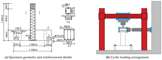
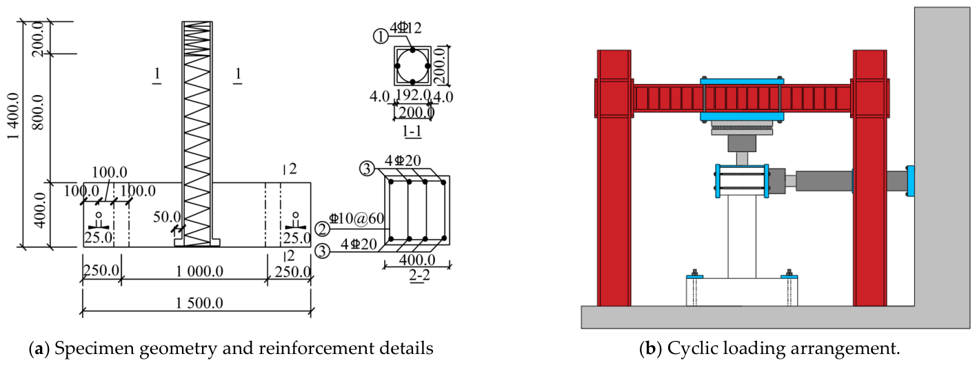
The geometric details and experimental loading configuration of the selected specimen are shown in Figure 1. The specimen consisted of a square steel tube, concrete core, longitudinal reinforcement and high-strength spiral stirrups. The column had a square cross-section with a side length of 200 mm and a total height of 1400 mm. A constant axial compression load was first applied at the column top, followed by cyclic lateral displacement loading to simulate the seismic response of the composite column.
Figure 1.
Geometry details and loading configuration of the SHSCC specimen.
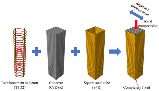
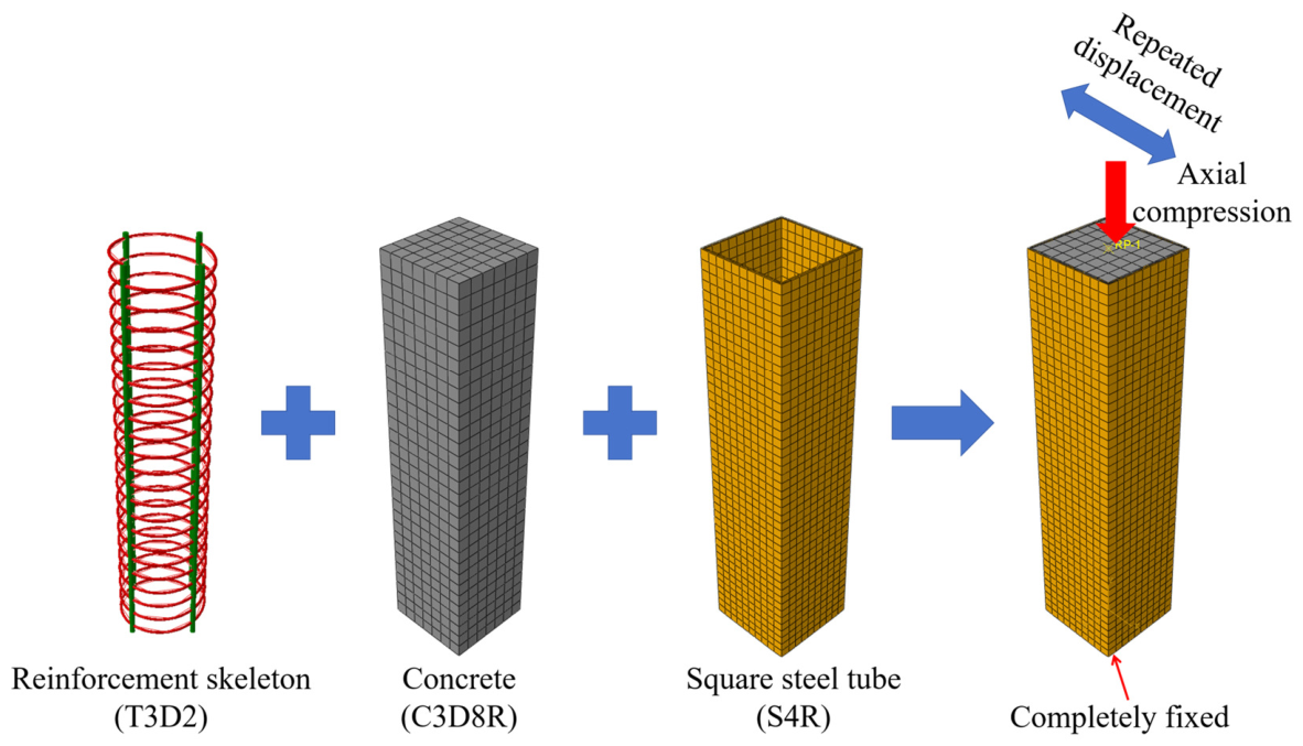
In the finite element model, the geometric dimensions and reinforcement arrangement were consistent with those of the experimental specimen. The reinforcement cage, concrete core, and square steel tube were established separately and assembled to simulate the composite confinement effect, as shown in Figure 2. Since the bottom foundation mainly functioned as a loading and anchorage component during the experiment and had negligible influence on the deformation behaviour of the column itself, the foundation was not explicitly modelled. Instead, the bottom surface of the column was directly fully constrained to simulate the fixed boundary condition. At the top of the column, a constant axial compression load was applied first, followed by cyclic lateral displacement loading to reproduce the experimental loading procedure.
Figure 2.
Finite element model configuration of the SHSCC column.
2.2. Material Constitutive Models
2.2.1. Concrete
The concrete core was modelled using the Concrete Damaged Plasticity (CDP) model in ABAQUS, which has been widely applied to simulate the nonlinear behaviour of concrete under cyclic loading [23,24,25]. The CDP model is capable of representing the stiffness degradation, irreversible plastic deformation, and tensile cracking and compressive crushing of concrete. The concrete material properties were determined from the experimental measurements reported for the reference specimen [22]. The measured average cubic compressive strength was 26.4 MPa, corresponding to an axial compressive strength of 20.0 MPa. The latter value was adopted as the concrete compressive strength fc in the FE model.
The compressive stress–strain relationship of concrete was defined according to the GB 50010-2010 [26]. The ascending branch is expressed as
where
For the descending branch,
where fc is the axial compressive strength of concrete, Ec is the elastic modulus, εc is the peak compressive strain, and αc is the descending branch parameter specified in GB 50010-2010 [26].
The tensile behaviour of concrete was also defined according to GB 50010-2010. The tensile stress increased linearly before reaching the tensile strength and subsequently decreased according to the tensile softening relationship. To account for the stiffness degradation of concrete under cyclic loading, the tensile and compressive damage variables were explicitly defined based on the degradation of the secant stiffness. The compressive and tensile damage variables were calculated as follows:
where dc and dt are the compressive and tensile damage variables, respectively; σc and σt are the corresponding compressive and tensile stresses; εc and εt are the corresponding total strains; and E0 is the initial elastic modulus of concrete. The damage variables range from 0 to 1, where 0 represents the undamaged state and 1 represents complete stiffness degradation.
The corresponding compressive and tensile inelastic strains required by the CDP model were determined by subtracting the elastic strain from the total strain as follows:
The calculated damage variables, together with the corresponding inelastic strains, were specified in ABAQUS to define the damage evolution of concrete. During cyclic loading, the progressive increase in dt and dc represents the accumulation of tensile cracking and compressive crushing, respectively, resulting in degradation of the effective stiffness during unloading and reloading. This treatment enables the CDP model to account for the progressive deterioration of concrete associated with repeated cyclic loading.
The CDP parameters adopted in this study were a dilation angle of 30°, eccentricity of 0.1, fbo/fco = 1.16, K = 0.667, and viscosity parameter of 0.001, which have been widely used in previous numerical studies of concrete-filled steel tubular members.
It should be noted that the compressive stress–strain relationship specified in GB 50010-2010 is essentially derived from the uniaxial behaviour of concrete and therefore does not explicitly incorporate the enhancement in concrete strength and deformation capacity induced by the composite confinement of the external square steel tube and internal high-strength spiral reinforcement. In the present FE model, the confinement effect was not directly introduced into the input uniaxial constitutive relationship to avoid double counting the confinement contribution. Instead, the GB 50010-2010 relationship was adopted to define the basic material response of unconfined concrete, while the confinement effect was generated through the interaction among the concrete core, steel tube, and spiral reinforcement within the three-dimensional CDP framework. As the concrete expands laterally, the surrounding steel tube and spiral reinforcement provide passive confinement, and the resulting multiaxial stress state and confinement-induced enhancement are consequently reflected in the numerical response.
Nevertheless, this modelling strategy has certain limitations. The standard uniaxial constitutive relationship cannot explicitly describe the confinement-dependent evolution of concrete strength, peak strain, and post-peak ductility under high confining pressure. Consequently, the plastic deformation and stiffness degradation of highly confined concrete may not be fully reproduced at the material constitutive level. Despite these limitations, the adopted approach provides a relatively simple and consistent modelling framework, and its applicability to the SHSCC columns considered in this study is further assessed through comparison with the experimental results in Section 2.6.
2.2.2. Steel Tube
The square steel tube was modelled using a bilinear elastoplastic constitutive model with isotropic hardening [7]. The elastic modulus and Poisson’s ratio were taken as 206 GPa and 0.30, respectively. The yielding behaviour followed the von Mises yield criterion, while the post-yield response was described using a linear hardening relationship with a tangent modulus of 0.01Es.
The constitutive relationship can be expressed as
where Es is the elastic modulus and fy is the yield strength, εy = fy/Es.
The material properties of the steel tube were taken from the experimental measurements reported in the reference study [22]. The measured yield strength fy and ultimate strength fu of the Q235 square steel tube were 322 MPa and 472 MPa, respectively. It should be noted that isotropic hardening does not explicitly reproduce the Bauschinger effect associated with reversed cyclic loading. Kinematic or combined hardening models can provide a more detailed representation of cyclic steel behaviour, particularly during unloading and load reversal. In the present study, the bilinear isotropic hardening model was retained because the primary objective was to reproduce the global cyclic response and conduct comparative parametric analyses, rather than to characterize the detailed cyclic constitutive behaviour of the steel material. The satisfactory agreement between the numerical and experimental hysteretic and skeleton responses indicates that this simplified model provides an acceptable representation for the present purpose. Nevertheless, the neglect of the Bauschinger effect may contribute to discrepancies in the unloading and reloading branches, and this constitutes a limitation of the present model.
2.2.3. Spiral Stirrups
Both the longitudinal reinforcement and the high-strength spiral stirrups were modelled using embedded truss elements and were assumed to follow a bilinear elastoplastic constitutive relationship with linear post-yield hardening [27]. The constitutive model adopted for the reinforcement was identical to that used for the steel tube, except that the corresponding elastic modulus and yield strength were determined according to the measured material properties of HRB400 longitudinal bars and CRB800 high-strength spiral stirrups. The measured yield and ultimate strengths were 457 MPa and 589 MPa, respectively, for the HRB400 longitudinal reinforcement, and 809 MPa and 952 MPa, respectively, for the CRB800 high-strength spiral stirrups [22]. The post-yield tangent modulus was taken as 0.01Er.
The stress–strain relationship of the reinforcement can therefore be expressed as
where Er and fy denote the elastic modulus and yield strength of the reinforcement, respectively.
The use of high-strength spiral stirrups provides stronger lateral confinement to the concrete core, thereby delaying crack propagation and improving the ductility and post-peak deformation capacity of SHSCC columns under cyclic loading.
2.3. Interaction
The interaction relationships among the steel tube, concrete core, and reinforcement were established to accurately simulate the composite action of the SHSCC column. The longitudinal reinforcement and high-strength spiral stirrups were embedded in the concrete using the Embedded Region constraint in ABAQUS, assuming a perfect bond between the reinforcement and the surrounding concrete. Under this assumption, the reinforcement shared the same displacement field as the concrete, and the bond-slip effect was neglected.
The interface between the square steel tube and the concrete core was defined using a surface-to-surface contact algorithm. In the normal direction, hard contact was adopted to prevent penetration while allowing separation after contact. In the tangential direction, the penalty friction formulation was employed to simulate the interfacial friction between the steel tube and concrete, with a friction coefficient of 0.30 [7]. This contact definition permits relative sliding at the steel–concrete interface while ensuring effective load transfer during cyclic loading, thereby providing a reasonable representation of the confinement effect of the steel tube on the concrete core.
The contact interactions adopted in this study have been widely used in previous numerical investigations of concrete-filled steel tubular members and have been demonstrated to provide satisfactory agreement with experimental results. The perfect-bond assumption between the reinforcement and concrete is also commonly adopted in finite element analyses of reinforced concrete and concrete-filled steel tubular members when the primary objective is to predict the global structural response rather than local bond-slip behaviour. Explicitly modelling bond-slip requires additional interface parameters, such as bond strength, slip evolution, and cyclic bond degradation, which are generally dependent on reinforcement geometry, concrete properties, confinement conditions, and loading history. These parameters were not independently measured in the reference experiments used for model validation, and introducing an assumed bond-slip relationship would therefore introduce additional modelling uncertainties.
It is acknowledged that the perfect-bond assumption may overestimate the reinforcement–concrete interaction after significant cracking and yielding, particularly under large cyclic deformations, and may consequently affect the predicted stiffness degradation, energy dissipation, and local crack development. Nevertheless, the satisfactory agreement between the numerical and experimental hysteretic responses indicates that the influence of this simplification on the global response is acceptable within the scope of the present study. Therefore, the Embedded Region approach was retained to maintain a consistent and computationally efficient modelling framework for the subsequent parametric analyses. The explicit consideration of cyclic bond-slip behaviour may be investigated in future studies when detailed bond-slip experimental data are available. Consequently, the adopted interaction strategy is considered appropriate for simulating the cyclic behaviour of SHSCC columns.
2.4. Mesh Sensitivity
The concrete core, square steel tube, and reinforcement were discretized using different element types according to their geometric characteristics and mechanical behaviour. The concrete core was modelled using eight-node three-dimensional solid elements with reduced integration (C3D8R), while the square steel tube was simulated using four-node reduced-integration shell elements (S4R). The longitudinal reinforcement and high-strength spiral stirrups were represented by two-node three-dimensional truss elements (T3D2). Reduced-integration elements were adopted to improve computational efficiency while maintaining sufficient accuracy in the nonlinear cyclic analysis.
A mesh sensitivity analysis was conducted to determine an appropriate balance between numerical accuracy and computational cost. Four mesh schemes with progressively refined element sizes were examined, as summarized in Table 1. The maximum lateral load and computational time obtained from each mesh scheme were compared, and the experimental average peak load of 144.0 kN was used to evaluate the prediction accuracy. As the mesh was refined from M1 to M3, the predicted maximum lateral load increased from 128.6 to 133.2 kN, while the difference between the M2 and M3 predictions was only approximately 2.3%. The corresponding difference from the experimental result decreased from 10.7% to 7.5%, indicating that the numerical response tended to stabilize within this mesh range. Further refinement to M4 increased the predicted peak load to 148.2 kN and reduced the difference from the experimental result to 2.9%; however, the computational time increased substantially from 1.4 h to 3.6 h.
Table 1.
Mesh convergence analysis of the FE model.
Considering both numerical accuracy and computational efficiency, a nominal mesh size of 25 mm was adopted for the square steel tube to adequately capture local stress concentrations and potential local buckling of the thin-walled steel plates. A mesh size of 30 mm was used for the concrete core, longitudinal reinforcement, and spiral stirrups. The adopted M3 mesh predicted the experimental peak load with a difference of 7.5%, while requiring only approximately 39% of the computational time of the finest M4 mesh. Therefore, the M3 mesh was considered to provide a reasonable compromise between prediction accuracy and computational efficiency and was employed in all subsequent finite element analyses.
2.5. Boundary Conditions
The boundary conditions and loading protocol of the finite element model were established to reproduce the experimental loading conditions. As shown in Figure 2, the bottom surface of the column was fully constrained to simulate the fixed support in the test. All translational and rotational degrees of freedom at the column base were restrained, thereby representing a rigidly fixed boundary condition.
A constant axial compression load was first applied to the top of the column prior to the cyclic loading. To maintain consistency with the experimental program, the axial compression ratio was set to 0.45, corresponding to an axial load of approximately 825 kN. After the axial load reached the target value and remained constant throughout the analysis, cyclic lateral displacement was subsequently imposed at the top of the column to simulate the low-cycle reversed loading. Simplified in the finite element simulation, for the first five displacement levels, the amplitude increased from 1 mm to 5 mm in increments of 1 mm. Afterwards, the displacement amplitude increased in increments of 3 mm, with one cycle applied to each level until the lateral resistance decreased to approximately 85% of the peak load.
2.6. Analysis Procedure
The nonlinear analysis was performed using the Static, General procedure in ABAQUS/Standard. Geometric nonlinearity was activated (NLGEOM = ON) throughout the analysis to account for the effects of large deformation and changes in structural geometry during cyclic loading, which is essential for capturing the development of local buckling of the square steel tube.
The analysis consisted of two sequential loading stages. First, the prescribed axial compressive load was applied to the top of the column and maintained constant. Subsequently, the cyclic lateral displacement history corresponding to the experimental loading protocol was imposed at the loading point while the axial load remained unchanged. The nonlinear equilibrium equations were solved incrementally using the automatic incrementation scheme in ABAQUS/Standard. It should be noted that these numerical increments are distinct from the prescribed cyclic displacement increments described in Section 2.5. The maximum and minimum increment sizes were specified as 0.1 and 0.001, respectively, allowing relatively large increments during stable response while automatically reducing the increment size when strong material or geometric nonlinearities developed. This strategy improved convergence during yielding, concrete damage evolution, and local buckling of the steel tube.
The combined consideration of material nonlinearity through the constitutive models and geometric nonlinearity through the NLGEOM option enabled the numerical model to reproduce the progressive nonlinear response of the SHSCC columns under combined constant axial compression and reversed cyclic lateral loading.
2.7. Model Validation
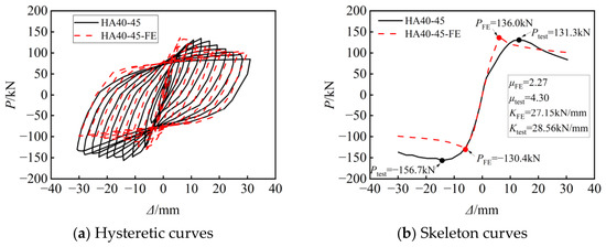
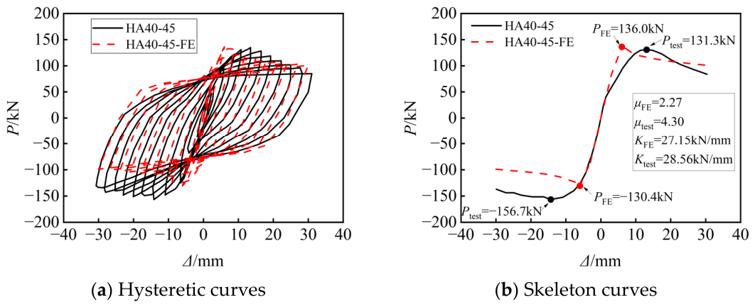
The accuracy of the proposed finite element model was evaluated by comparing the numerical results with the experimental results of specimen HA40-45 in terms of the hysteretic response, skeleton curve, peak lateral load, and failure mode. Figure 3a compares the experimental and numerical hysteretic curves. The finite element model generally reproduced the development of the hysteretic response, including the initial stiffness, yielding process, progressive enlargement of the hysteretic loops, and post-peak strength degradation. The numerical curves also captured the spindle-shaped hysteretic characteristics observed in the experiment. Some differences were observed in the unloading and reloading paths, with the numerical response exhibiting a slightly different pinching degree from the experimental curve. Nevertheless, the overall cyclic response and variation in lateral resistance were satisfactorily reproduced.
Figure 3.
Comparison between experimental and numerical responses of specimen HA40-45.
As shown in Figure 3b, the numerical skeleton curve was generally consistent with the experimental curve in terms of the ascending branch, peak response, and subsequent descending tendency. In the positive loading direction, the predicted peak lateral load was 136.0 kN, compared with the experimental value of 131.3 kN, corresponding to an error of approximately 3.6%. In the negative loading direction, the numerical and experimental peak loads were −130.4 kN and −156.7 kN, respectively, giving an absolute error of approximately 16.8%. This relatively large discrepancy should be interpreted together with the evident asymmetry observed in the experimental response. The absolute experimental peak load in the negative direction (156.7 kN) was approximately 19.3% higher than that in the positive direction (131.3 kN), whereas the corresponding numerical peak loads (136.0 and 130.4 kN) differed by only approximately 4.2%. Since the specimen geometry and reinforcement arrangement were essentially symmetric with respect to the loading direction, the pronounced positive–negative difference observed experimentally is likely associated with unavoidable experimental uncertainties and asymmetric effects, such as initial geometric imperfections, slight loading eccentricity, material heterogeneity, boundary-condition deviations, and asymmetric local buckling. These factors were not explicitly reproduced in the idealized FE model, which consequently exhibited a more symmetric response. Taking the average absolute peak loads in the two loading directions, the numerical prediction was approximately 133.2 kN, whereas the experimental value was approximately 144.0 kN, corresponding to an overall difference of about 7.5%. The average value is reported here only as an additional indicator of the overall lateral resistance rather than as a means of obscuring the larger error in the negative loading direction. In addition to the peak lateral load, the initial stiffness and ductility coefficient were also compared. The numerical and experimental initial stiffnesses were 27.15 and 28.56 kN/mm, respectively, corresponding to a difference of only 4.9%. The numerical ductility coefficient was 2.27, compared with the experimental value of 4.30, indicating that the model underestimated the deformation capacity. This discrepancy may be attributed to the idealized material, interface, and boundary conditions adopted in the FE model, which can affect the predicted yield and ultimate displacements. Therefore, the subsequent ductility results are primarily used to evaluate relative parametric trends rather than absolute deformation capacity. Therefore, although the model underestimated the negative-direction capacity and ductility, the close prediction in the positive direction, the reasonable prediction of the mean lateral resistance, and the overall agreement of the hysteretic and skeleton curves indicate that the model can reasonably capture the principal cyclic response and is suitable for comparative parametric analyses within the investigated ranges.
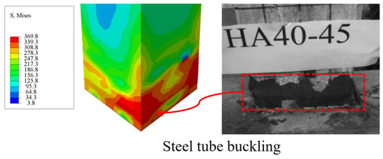
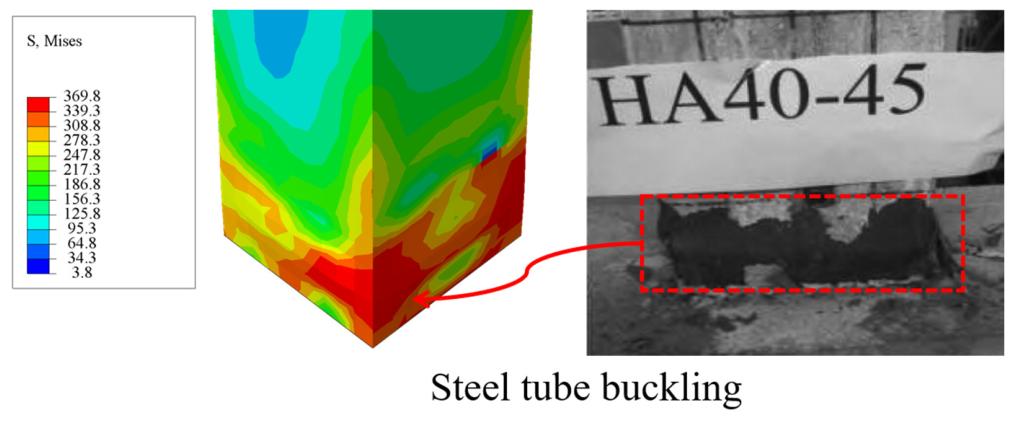
Figure 4 compares the numerical and experimental failure modes. Both results showed pronounced outward local buckling of the square steel tube near the column base, where the bending moment and compressive stress were concentrated. The numerical model accurately predicted the location and general pattern of the steel tube buckling observed in the test, demonstrating that it could reasonably capture the governing flexural failure mechanism of the SHSCC column. The differences between the numerical and experimental results may be attributed to several idealizations. First, the concrete and steel materials were assumed to be homogeneous, whereas unavoidable material variability and initial defects existed in the experimental specimen. Second, the reinforcement–concrete bond slip was neglected because the reinforcement was embedded in the concrete. Third, the foundation was not explicitly modelled, and the column base was simplified as a fully fixed boundary. In addition, residual stresses, initial geometric imperfections, weld effects, slight loading eccentricity, and possible asymmetric local buckling of the steel tube were not considered. These experimental uncertainties and modelling idealizations may accumulate differently under opposite loading directions and are considered to be the main possible reasons for the more pronounced positive–negative asymmetry observed in the experimental response than in the numerical results. Despite these discrepancies, the finite element model reasonably reproduced the main hysteretic characteristics, overall load-carrying capacity, skeleton response, and failure mode of the reference specimen. The validated model was therefore employed in the subsequent parametric study primarily to identify comparative trends associated with individual parameters. Nevertheless, because the validation was conducted against a single specimen, the present validation does not establish quantitative accuracy over the entire parameter space considered. Accordingly, the parametric results should be interpreted as numerical trends within the investigated ranges rather than universally applicable predictions. Further experimental validation covering a wider range of axial compression ratios, material strengths, and geometric parameters is required before generalized design predictions can be established.
Figure 4.
Comparison of the numerical and experimental failure modes of specimen HA40-45.
3. Parametric Study
3.1. Parameters
To investigate the influence of key parameters on the cyclic behaviour of SHSCC columns, a total of 24 finite element models were established based on the validated reference model (HA40-45-FE) using the control-variable method. This approach was adopted to isolate the individual influence of each parameter while maintaining a manageable number of numerical simulations. As summarized in Table 2, five design parameters were considered, including the axial compression ratio (n), concrete strength grade, spiral spacing (S), spiral bar diameter (D), and steel tube thickness (t). The axial compression ratio varied from 0.10 to 0.90, while the concrete strength ranged from C30 to C60. The spiral spacing was selected as 20, 40, 60, 80, 100, 150 and 200 mm, the spiral bar diameter ranged from 8 to 12 mm, and the steel tube thickness varied from 4 to 7 mm. The selected parameter ranges were determined with reference to the configurations adopted in previous experimental studies of spiral-confined square CFST columns and were extended appropriately to cover representative low-to-high confinement and axial compression levels. The ranges of S = 20–200 mm, D = 8–12 mm, and t = 4–7 mm were selected to represent practical variations in transverse reinforcement and steel-tube confinement, while n = 0.10–0.90 was adopted to systematically examine the transition from low to high axial compression levels [14,19,28].
Table 2.
Parameters and numerical results of finite element models.
It should be noted that no separate FE-n5 model was established because the reference model HA-40-45-FE, with an axial compression ratio of n = 0.45, was directly included in the axial compression ratio comparison. Except for the investigated parameter, all remaining geometric dimensions, material properties and loading conditions were kept identical to those of the reference model. The peak lateral load (Pp), initial stiffness (K), ductility coefficient (μ), and energy-related index (E) obtained from the numerical simulations are also summarized in Table 2 and were subsequently used to quantitatively evaluate the influence of each parameter on the cyclic performance of SHSCC columns.
It should be noted that the control-variable method adopted herein primarily evaluates the individual effects of the investigated parameters and does not explicitly quantify their interaction effects. Potential interactions may exist among these parameters; for example, the effectiveness of spiral reinforcement may depend to some extent on the axial compression level. A rigorous evaluation of such interactions would require a dedicated multi-factor sampling scheme, such as factorial design or response surface methodology, with additional FE simulations covering combinations of the investigated parameters. The present 24 models were designed for single-parameter comparisons rather than statistical identification of interaction terms; therefore, fitting a response surface with interaction terms directly to the current dataset may lead to insufficient statistical support. Accordingly, the conclusions drawn from the present parametric study are primarily limited to the individual influence and general trends of each parameter within the investigated ranges. Systematic multi-parameter interaction analysis will be considered in future studies to further develop design-oriented recommendations. Because the investigated parameters were varied over different physical ranges and scales, the percentage changes reported herein are used only to describe the response variation within the respective investigated range and should not be interpreted as a normalized ranking of parameter importance.
3.2. Hysteretic and Skeleton Curves
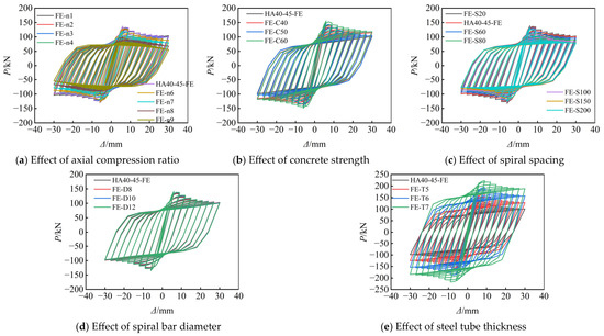
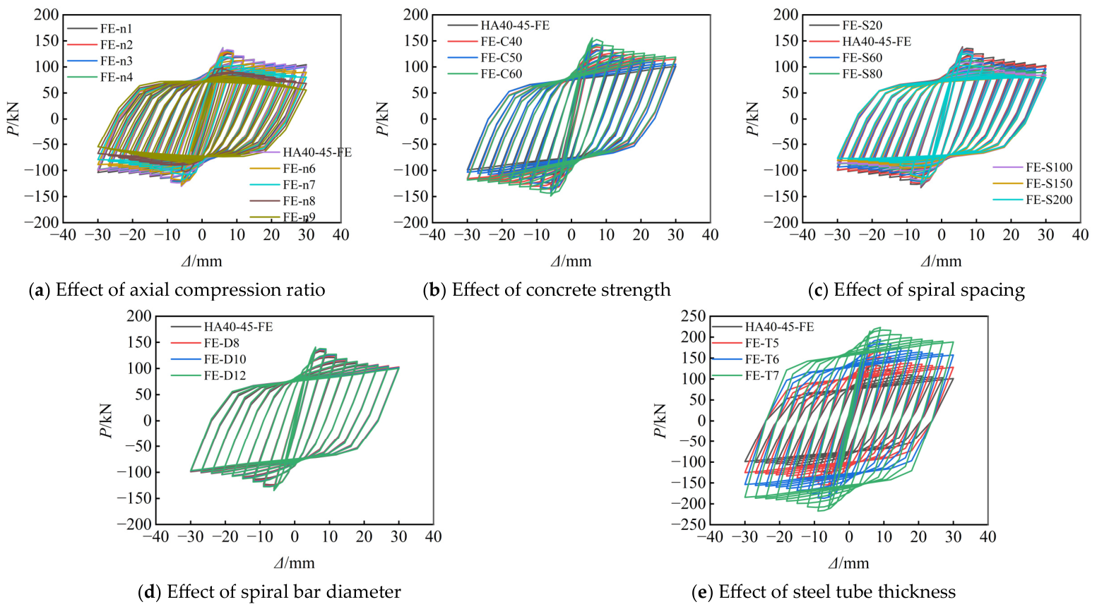
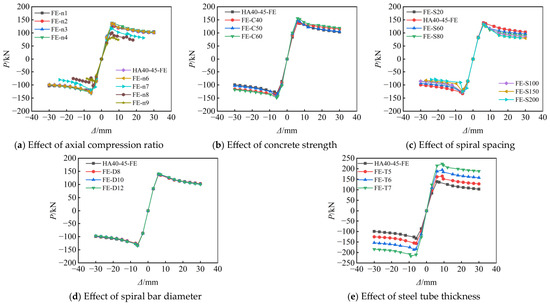
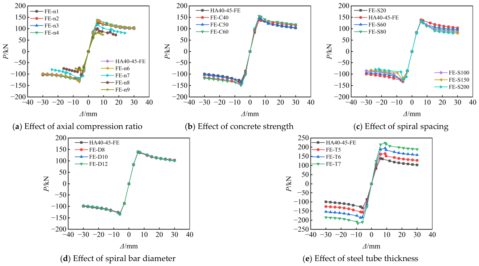
Figure 5 and Figure 6 present the hysteretic and corresponding skeleton curves of the SHSCC columns with different axial compression ratios, concrete strengths, spiral spacings, spiral diameters and steel tube thicknesses. Overall, all specimens exhibited stable cyclic responses throughout the loading process. The hysteretic loops gradually expanded with increasing displacement amplitude, while the corresponding skeleton curves showed a typical elastic–plastic behaviour characterized by an initial linear ascending stage, followed by yielding and a gradual post-peak softening stage. No sudden strength degradation or brittle failure was observed before reaching the maximum lateral load, indicating that the composite confinement provided by the steel tube, high-strength spiral reinforcement and core concrete ensured satisfactory cyclic deformation capacity.
Figure 5.
Hysteretic curves of SHSCC columns with different parameters.
Figure 6.
Skeleton curves of SHSCC columns with different parameters.
As shown in Figure 5a–e, all specimens exhibited relatively full spindle-shaped hysteretic loops with only slight pinching near the load reversal points, indicating effective interaction among the steel tube, spiral reinforcement and concrete during cyclic loading. The influence of the investigated parameters on the overall hysteretic morphology was generally similar, while the degree of variation differed. Increasing the axial compression ratio (Figure 5a) resulted in slightly narrower hysteretic loops in the large-displacement stage, indicating reduced deformation capacity. In contrast, varying the concrete strength (Figure 5b) and spiral diameter (Figure 5d) produced only minor changes in the overall loop morphology, suggesting that these parameters had little influence on the cyclic deformation pattern within the investigated range. Increasing the spiral spacing (Figure 5c) slightly reduced the fullness of the hysteretic loops because of the weakened confinement provided by the transverse reinforcement. Among all parameters, the steel tube thickness (Figure 5e) had the most pronounced effect on the hysteretic response. Thicker steel tubes produced fuller hysteretic loops with larger enclosed areas and less obvious pinching, demonstrating stronger confinement of the core concrete and more stable cyclic behaviour.
The corresponding skeleton curves shown in Figure 6a–e exhibit consistent development trends for all specimens. The curves initially increased almost linearly, followed by a nonlinear hardening stage before reaching the peak load, and finally entered a gradual descending branch without abrupt strength loss. Compared with the hysteretic curves, the influence of each parameter on the skeleton curves can be more clearly identified. As the axial compression ratio increased (Figure 6a), the post-peak descending branch became steeper, indicating reduced post-peak deformation stability. Increasing the concrete strength (Figure 6b) primarily elevated the load level while producing little change in the overall curve shape. Increasing the spiral spacing (Figure 6c) accelerated the post-peak strength degradation because of the reduced confinement efficiency, whereas changing the spiral diameter (Figure 6d) resulted in only slight differences in the skeleton curves. Increasing the steel tube thickness (Figure 6e) noticeably improved the post-peak response, leading to a flatter descending branch and enhanced deformation stability, which can be attributed to the stronger confinement and delayed local buckling of the steel tube.
3.3. Ultimate Load-Carrying Capacity
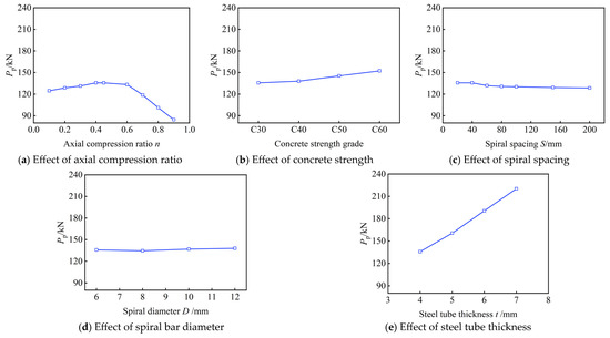
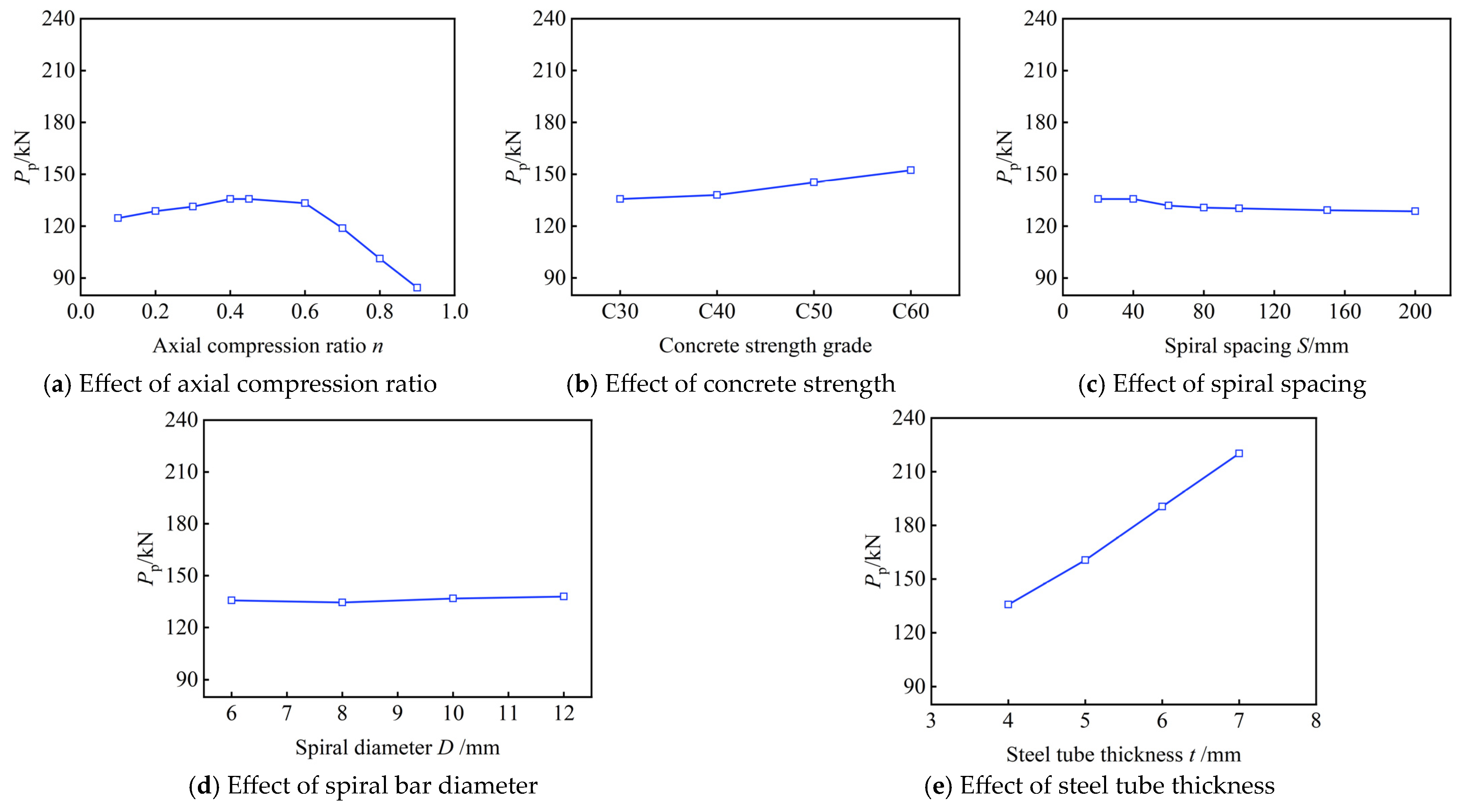
Figure 7 presents the influence of different parameters on the ultimate lateral load of SHSCC columns. Overall, the ultimate load was significantly affected by the axial compression ratio, concrete strength, spiral spacing and steel tube thickness, whereas the influence of spiral bar diameter was relatively limited within the investigated range. As shown in Figure 7a, the ultimate load initially increased and then decreased with increasing axial compression ratio, reaching the maximum value of 135.7 kN at an axial compression ratio of 0.45. Compared with the specimen at n = 0.10, the ultimate load increased by 8.8% at n = 0.45, indicating that an appropriate axial compression ratio enhanced the confinement effect of the steel tube and spiral reinforcement, thereby improving the load-carrying capacity. However, further increasing the axial compression ratio led to a rapid reduction in the ultimate load, which decreased to 84.4 kN at n = 0.90, corresponding to a reduction of 37.8% compared with the reference specimen. A similar influence of axial compression level on the cyclic behaviour of square spiral-confined CFST columns was reported by Hu et al. [14], who observed that a high axial load ratio intensified damage and adversely affected the deformation capacity of the columns.
Figure 7.
Effect of different parameters on the ultimate lateral load of SHSCC columns.
As illustrated in Figure 7b, increasing the concrete strength from C30 to C60 continuously improved the ultimate load from 135.7 kN to 152.3 kN, representing an increase of 12.2%, owing to the higher compressive resistance of the confined concrete core and the enhanced composite action between the steel tube and concrete. In contrast, increasing the spiral spacing from 20 mm to 200 mm resulted in a gradual reduction in the ultimate load from 135.7 kN to 128.6 kN (5.2% decrease), as shown in Figure 7c. A larger spiral spacing reduced the volumetric ratio of transverse reinforcement and weakened the confinement provided to the concrete core, leading to earlier development of concrete damage under cyclic loading. This trend is consistent with the experimental observations of Chen et al. [29] and Yuan et al. [19], who demonstrated that spiral reinforcement can enhance the confinement of the concrete core and that its configuration significantly affects the mechanical performance of square CFST columns. As shown in Figure 7d, varying the spiral bar diameter from 8 mm to 12 mm produced only a slight increase in the ultimate load from 134.5 kN to 137.9 kN (approximately 2.5%), indicating that increasing the spiral diameter alone contributed little to the overall bearing capacity within the investigated range because the external steel tube provided the dominant confinement. Within the investigated range, increasing the steel tube thickness produced a substantial increase in the ultimate load. As shown in Figure 7e, increasing the steel tube thickness from 4 mm to 7 mm increased the ultimate load from 135.7 kN to 220.2 kN, corresponding to an increase of approximately 62.3%. The thicker steel tube not only enhanced the axial and flexural resistance of the steel section but also provided stronger lateral confinement to the core concrete and effectively delayed local buckling of the steel tube, thereby markedly improving the ultimate load-carrying capacity of the SHSCC columns. The pronounced beneficial effect of steel tube thickness is also consistent with previous studies on CFST beam-columns, which showed that thicker steel tubes generally improve the overall strength and cyclic performance of composite columns [30].
3.4. Ductility
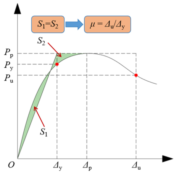
The ductility coefficient was calculated as the ratio of the ultimate displacement to the yield displacement:
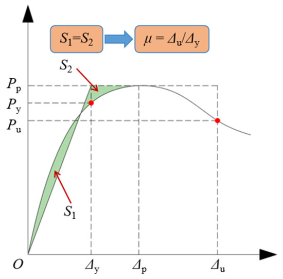
where Δy and Δu are the yield displacement and ultimate displacement, respectively. As illustrated in Figure 8, the yield displacement was determined using the equivalent energy method based on the skeleton curve. The idealized elastic–plastic curve was constructed such that the area enclosed by the idealized curve was equal to that under the actual skeleton curve up to the peak load, and the corresponding intersection was taken as the yield point. The ultimate displacement was defined as the displacement corresponding to 85% of the peak lateral load on the descending branch of the skeleton curve. When the load did not decrease to 85% of the peak load before the termination of loading, the displacement at the final loading point was taken as the ultimate displacement. The same procedure was applied consistently to all specimens, and the calculation model is illustrated in Figure 8.
Figure 8.
Calculation model of ductility coefficient.
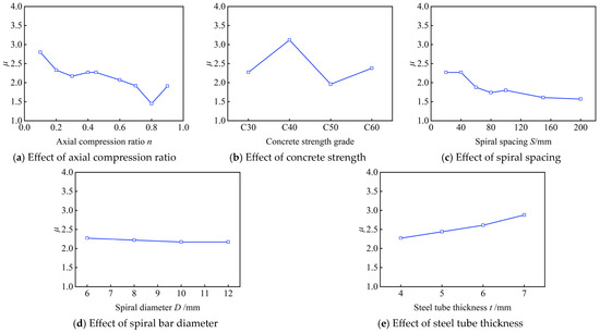
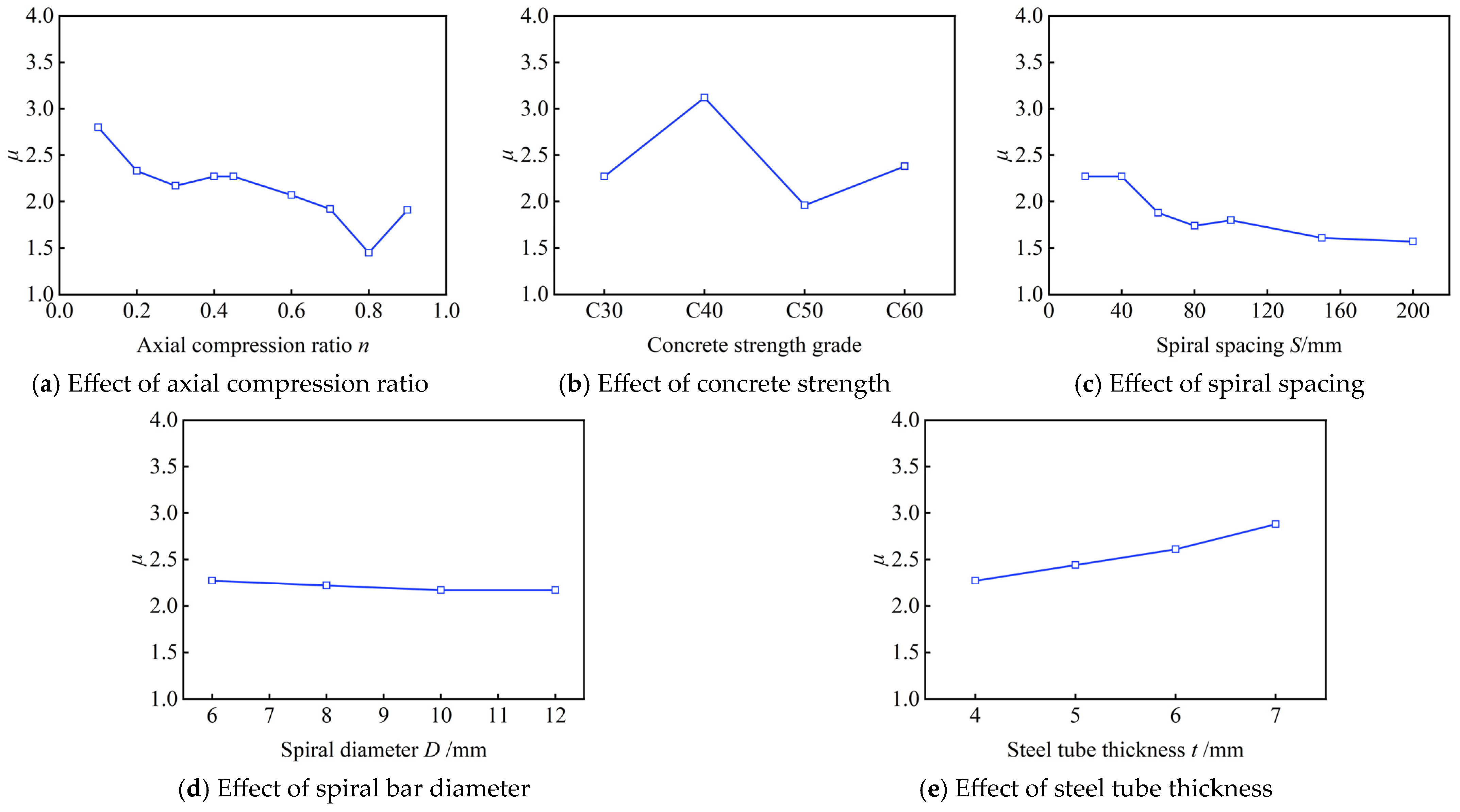
Figure 9 illustrates the influence of different parameters on the ductility coefficient of SHSCC columns. Overall, the ductility was considerably affected by the axial compression ratio, concrete strength, spiral spacing and steel tube thickness, whereas the influence of the spiral bar diameter was relatively insignificant. As shown in Figure 9a, the ductility coefficient generally decreased with increasing axial compression ratio, although local non-monotonic variations were observed at high axial compression ratios. Compared with the specimen at n = 0.10 (μ = 2.80), the ductility coefficient decreased to 1.91 at n = 0.90, corresponding to a reduction of approximately 31.8%. In particular, the ductility coefficient increased from 1.45 at n = 0.80 to 1.91 at n = 0.90. Because the ductility coefficient is defined as the ratio of the ultimate displacement to the yield displacement, its value is sensitive to changes in both characteristic displacements and to the shape of the post-peak skeleton curve. Therefore, local fluctuations may occur when severe nonlinear damage at high axial compression ratios alters the identified yield and ultimate points. Nevertheless, the overall reduction in ductility with increasing axial compression ratio remains evident. The higher axial compression ratio increased the compressive stress level in the concrete core, accelerating concrete crushing and local buckling of the steel tube during cyclic loading, thereby reducing the deformation capacity. This observation agrees with the experimental results of Hu et al. [14], who reported that the seismic deformation capacity of square spiral-confined high-strength CFST columns deteriorated under high axial load ratios. As shown in Figure 9b, increasing the concrete strength from C30 to C40 increased the ductility coefficient from 2.27 to 3.12, representing an increase of 37.4%, whereas further increasing the concrete strength to C50 reduced the ductility coefficient to 1.96, followed by a moderate increase to 2.38 at C60. This indicates that although moderate increases in concrete strength improved the integrity of the composite section, excessively high concrete strength reduced the deformability of the concrete core because of its increased brittleness. A comparable tendency was reported by Inai et al. [30], whose cyclic tests indicated that increasing concrete strength did not necessarily improve the overall deformation behaviour of CFT beam-columns, despite its contribution to strength. Figure 9c shows that increasing the spiral spacing from 20 mm to 200 mm gradually reduced the ductility coefficient from 2.27 to 1.57, corresponding to a decrease of 30.8%, owing to the reduction in transverse reinforcement ratio and the consequent weakening of confinement to the core concrete. The beneficial role of spiral confinement in improving the deformation capacity of square CFST columns has also been demonstrated experimentally by Chen et al. [29] and Hu et al. [28]. By contrast, increasing the spiral bar diameter from 8 mm to 12 mm resulted in only a slight reduction in ductility from 2.22 to 2.17 (approximately 2.3%), indicating that enlarging the spiral diameter alone had little influence on the overall deformation capacity within the investigated range. Within the investigated range, increasing the steel tube thickness produced a pronounced positive effect on ductility. As shown in Figure 9e, increasing the steel tube thickness from 4 mm to 7 mm increased the ductility coefficient from 2.27 to 2.88, corresponding to an increase of 26.9%. The thicker steel tube provided stronger confinement to the concrete core and effectively delayed local buckling, allowing the composite column to sustain larger inelastic deformation under cyclic loading and thereby exhibit superior ductility.
Figure 9.
Effect of different parameters on the ductility of SHSCC columns.
3.5. Stiffness Degradation
The stiffness degradation of SHSCC columns was evaluated based on the secant stiffness obtained from each displacement level of the cyclic loading. The stiffness at the ith loading cycle was calculated as:
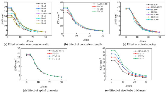
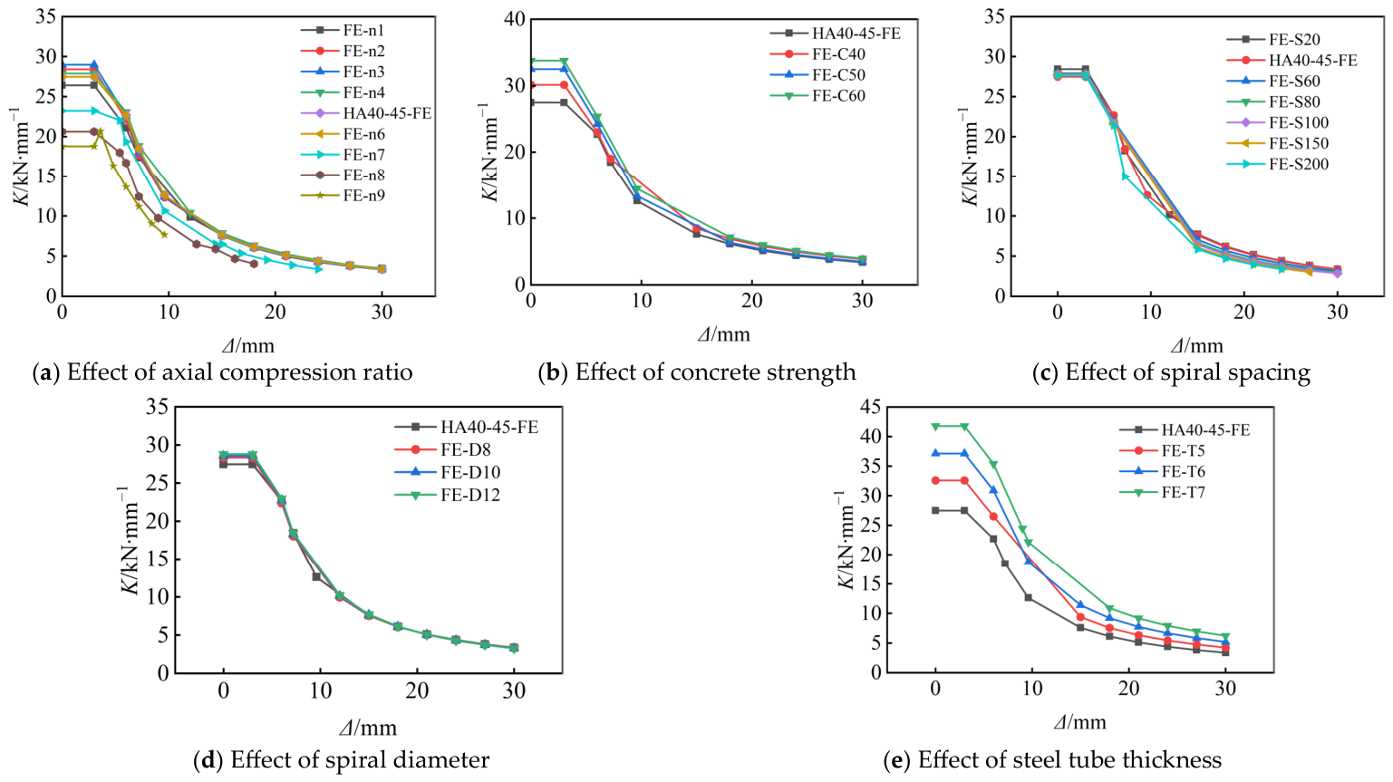
where Ki is the secant stiffness corresponding to the ith displacement amplitude; Pi+ and Pi− represent the peak positive and negative lateral loads, respectively; and Δi+ and Δi− denote the corresponding positive and negative displacements. Figure 10 presents the stiffness degradation curves of SHSCC columns with different parameters. Overall, all specimens exhibited a similar degradation tendency, characterized by a rapid decrease in stiffness during the early loading stage, followed by a gradual stabilization with increasing displacement amplitude. The rapid initial stiffness reduction was mainly attributed to the initiation and propagation of cracks in the concrete core and the deterioration of the steel tube–concrete interaction. With further cyclic loading, the confinement provided by the steel tube and spiral reinforcement effectively restrained the development of internal damage, resulting in a relatively stable degradation stage.
Figure 10.
Effect of different parameters on the stiffness degradation of SHSCC columns.
As shown in Figure 10a, increasing the axial compression ratio resulted in a continuous reduction in stiffness degradation resistance. The initial stiffness decreased from 28.4 kN/mm at n = 0.20 to 18.8 kN/mm at n = 0.90, corresponding to a reduction of 33.8%. The higher axial compression ratio increased the compressive damage level of the concrete core, accelerating stiffness deterioration under cyclic loading. In Figure 10b, increasing the concrete strength from C30 to C60 increased the initial stiffness from 27.5 kN/mm to 33.8 kN/mm (22.9% increase), because the higher-strength concrete provided greater resistance against cracking and enhanced the composite action between the steel tube and concrete. However, the overall degradation trend remained similar. As shown in Figure 10c, increasing the spiral spacing from 20 mm to 200 mm had a limited influence on the initial stiffness, which decreased slightly from 28.4 kN/mm to 27.6 kN/mm. Nevertheless, larger spiral spacing accelerated stiffness degradation due to the weakened confinement effect. Figure 10d indicates that increasing the spiral diameter from 8 mm to 12 mm produced negligible changes in stiffness, with the initial stiffness varying only from 28.4 kN/mm to 28.8 kN/mm, suggesting that the external steel tube played a dominant role in controlling the initial stiffness. Within the investigated range, increasing the steel tube thickness produced a pronounced increase in stiffness. As shown in Figure 10e, increasing the tube thickness from 4 mm to 7 mm increased the initial stiffness from 27.5 kN/mm to 41.8 kN/mm, representing an increase of 52.0%. The thicker steel tube enhanced the flexural rigidity of the composite section, improved confinement of the concrete core, and delayed local buckling, thereby effectively slowing down stiffness degradation.
3.6. Energy-Related Response
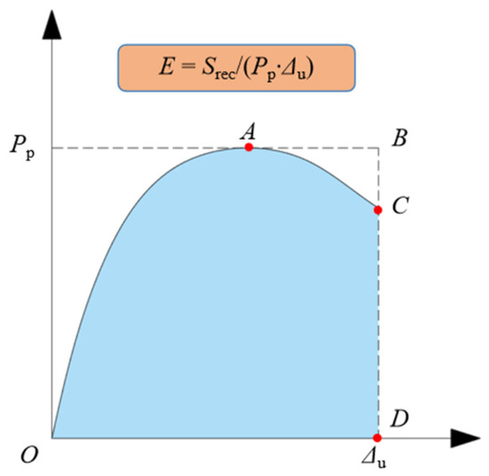
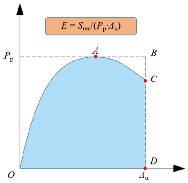
In conventional cyclic-loading studies, energy dissipation is generally quantified from the area enclosed by the hysteretic loops, such as the cumulative hysteretic energy or equivalent viscous damping ratio. In the present study, however, the parameter (E) is defined based on the skeleton curve and is therefore used as a comparative energy-related index rather than a direct measure of the energy dissipated within individual hysteretic loops. The energy-related index was calculated as:
where Srec represents the work-related area associated with the positive and negative branches of the skeleton curve, and the calculation method is shown in Figure 11.
Figure 11.
Calculation model of energy-related index.
Physically, Srec reflects the work associated with the lateral resistance and deformation capacity represented by the envelope response. Therefore, a larger E indicates a greater capacity of the member to sustain lateral resistance over a larger deformation range. This definition is particularly useful in the present parametric analysis because it provides a consistent scalar index for comparing the effects of different design parameters on the overall load–deformation response. However, it should be emphasized that this skeleton-based index does not represent the actual hysteretic energy dissipated during repeated loading, because the unloading and reloading paths and the enclosed areas of individual hysteretic loops are not explicitly included.
Accordingly, the physical meaning of E differs from that of conventional cumulative hysteretic energy and equivalent viscous damping. Cumulative hysteretic energy is obtained by summing the areas enclosed by successive hysteretic loops and represents the total energy dissipated throughout the loading history, whereas the equivalent viscous damping ratio characterizes the energy dissipated in a particular loading cycle relative to the corresponding elastic strain energy. The skeleton-based E adopted herein primarily characterizes the combined lateral resistance and deformation capacity of the envelope response. Therefore, comparisons based on E in the following discussion should be interpreted as relative comparisons among the investigated specimens rather than as direct quantification of their cumulative hysteretic energy dissipation.
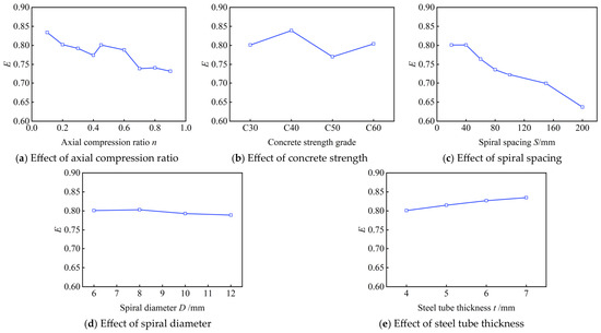
A higher value of E indicates a greater work-related capacity associated with the envelope load–deformation response. Figure 12 presents the influence of different parameters on the energy-related index E of SHSCC columns. Overall, the variation range of E was relatively limited (0.637–0.839), indicating that the investigated parameters produced different degrees of influence on the skeleton-based energy-related response within the considered ranges.
Figure 12.
Effect of different parameters on the energy dissipation of SHSCC columns.
As shown in Figure 12a, the energy-related index generally decreased with increasing axial compression ratio. The value of E decreased from 0.834 at n = 0.10 to 0.732 at n = 0.90, corresponding to a reduction of 12.2%. The increased axial compression ratio intensified compressive damage in the concrete core and accelerated the deterioration of the hysteretic behaviour, resulting in a reduced energy-related response. Figure 12b indicates that concrete strength had a non-monotonic influence on E. Increasing the concrete strength from C30 to C40 increased E from 0.801 to 0.839 (4.7% increase), while further increasing the strength to C50 reduced E to 0.770, followed by a slight recovery to 0.804 for C60. This phenomenon suggests that moderate-strength concrete improved the integrity of the composite section, whereas excessively high-strength concrete exhibited increased brittleness and reduced plastic deformation capacity. As shown in Figure 12c, increasing the spiral spacing produced the most pronounced variation in E among the investigated parameter ranges, reducing E from 0.801 at 20 mm to 0.637 at 200 mm, representing a decrease of 20.5%. A larger spiral spacing weakened the confinement effect and resulted in faster degradation of the hysteretic response, thereby reducing the skeleton-based energy-related response. In contrast, the spiral diameter had a limited influence on E, with only a slight variation from 0.803 (8 mm) to 0.789 (12 mm), as shown in Figure 12d. This indicates that the external steel tube dominated the confinement behaviour, while increasing the spiral diameter alone provided limited improvement. As illustrated in Figure 12e, steel tube thickness exhibited only a limited positive effect on E within the investigated range. Increasing the thickness from 4 mm to 7 mm increased E from 0.801 to 0.835, corresponding to an increase of only 4.2%. Therefore, although increasing the steel tube thickness substantially improved the load-carrying capacity, stiffness, and ductility, its influence on the skeleton-based energy-related index was relatively limited compared with that of spiral spacing.
3.7. Failure Mode Analysis
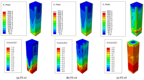
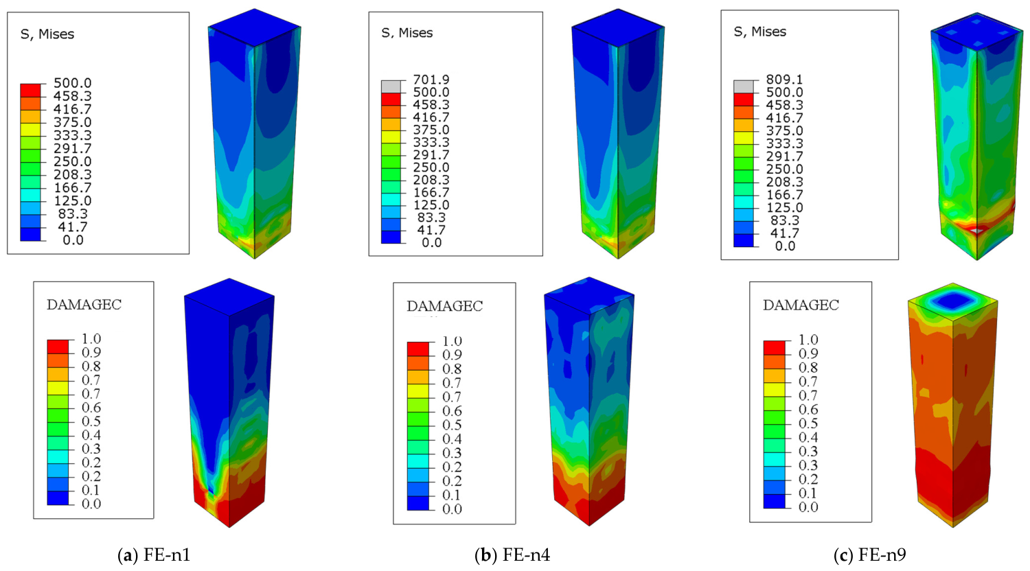
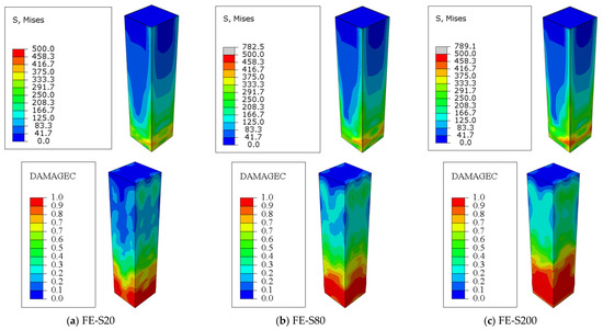
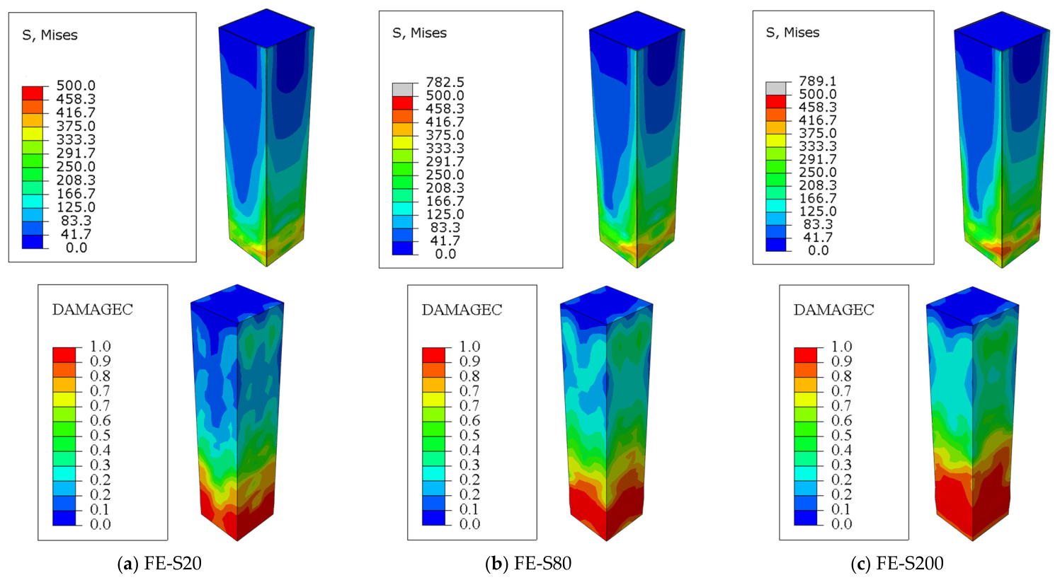
To further investigate the damage evolution and failure mechanism of SHSCC columns, the von Mises stress distributions of the steel tube and the compressive damage distributions (DAMAGEC) of the core concrete for specimens with different axial compression ratios and spiral spacings were examined, as shown in Figure 13 and Figure 14. In the DAMAGEC contours, a value approaching 1.0 represents severe compressive damage and substantial stiffness degradation of the concrete. These two parameters were selected because the axial compression ratio directly determines the stress level of the composite column, while the spiral spacing governs the confinement efficiency provided by the internal high-strength spiral reinforcement. The failure patterns of other specimens with different concrete strengths, spiral diameters and steel tube thicknesses were generally similar; therefore, they are not presented separately.
Figure 13.
Stress and concrete compressive damage distributions of SHSCC columns with different axial compression ratios.
Figure 14.
Stress and concrete compressive damage distributions of SHSCC columns with different spiral spacings.
As shown in Figure 13, the axial compression ratio significantly affected the stress distribution of the steel tube and the compressive damage development of the core concrete. For the specimen with a low axial compression ratio (FE-n1), the high-stress region was mainly concentrated near the bottom region of the column, while most of the steel tube remained in a relatively low-stress state. The corresponding concrete compressive damage was also mainly concentrated in the lower part of the column, with relatively limited damage in the upper region. With an increasing axial compression ratio (FE-n4), the stress concentration gradually extended upward from the column base, and the high-stress zone became more pronounced due to the increased compressive demand imposed on the concrete core and steel tube. Meanwhile, the concrete compressive damage progressively extended upward, indicating an expansion of the severely damaged region with increasing axial compression. When the axial compression ratio increased to 0.9 (FE-n9), a large high-stress region developed near the column base and extended along the steel tube surface. More importantly, the DAMAGEC contour shows that severe compressive damage occupied a substantially larger portion of the concrete core, with damage values approaching 1.0 over extensive regions. This indicates that the high axial compression ratio significantly accelerated the accumulation and propagation of concrete compressive damage. The extensive crushing and stiffness degradation of the concrete weakened its internal support to the square steel tube, which, together with the increased compressive demand, promoted stress concentration and local instability of the tube wall. This phenomenon explains the deterioration of ductility and post-peak behaviour observed at high axial compression ratios, where excessive compressive stress accelerates damage accumulation and reduces deformation capacity.
The influence of spiral spacing on the failure characteristics is illustrated in Figure 14. Compared with the specimens with larger spiral spacings, FE-S20 exhibited a relatively uniform stress distribution and a limited high-stress region, demonstrating that dense spiral reinforcement effectively enhanced the confinement of the concrete core and delayed damage development. The DAMAGEC distribution further confirms this confinement effect. For FE-S20, severe compressive damage was mainly concentrated near the column base, while the upper and middle regions of the concrete core maintained relatively low damage levels. As the spiral spacing increased to 80 mm and 200 mm, the stress concentration near the column base became increasingly evident, accompanied by a wider high-stress zone along the steel tube. Correspondingly, the compressive damage zone of the concrete gradually extended upward, and a larger portion of the core concrete exhibited moderate-to-severe damage. This indicates that increasing the spiral spacing weakened the lateral restraint on concrete dilation and allowed compressive damage to propagate more extensively along the column height. This change can be attributed to the reduction in volumetric reinforcement ratio and weakened lateral restraint provided by the spiral stirrups. With closer spiral spacing, the internal spiral reinforcement more effectively restrains the lateral expansion of the core concrete, thereby delaying compressive damage and maintaining the internal support provided by the concrete to the external steel tube. Conversely, increasing the spiral spacing weakens this inner confinement, accelerates concrete damage, and consequently reduces the effectiveness of the cooperative confinement between the spiral reinforcement, concrete core, and external steel tube. Therefore, reducing spiral spacing is beneficial for improving the confinement efficiency and maintaining the integrity of SHSCC columns under cyclic loading.
4. Conclusions
The cyclic behaviour of square steel tube–high-strength spiral stirrup composite confined concrete (SHSCC) columns was investigated through validated finite element analysis and comprehensive parametric studies. Based on the numerical results, the following conclusions can be drawn:
(1) The proposed finite element model reasonably reproduced the overall hysteretic response, skeleton curves and failure mode of the selected experimental specimen. The differences in peak lateral load were 3.6% and 16.8% in the positive and negative directions, respectively, with a 7.5% difference in the average absolute peak load. Considering that validation was conducted against one specimen, the model is considered suitable for investigating general parametric trends within the ranges considered in this study, while its broader applicability requires further experimental validation.
(2) All SHSCC columns exhibited stable spindle-shaped hysteretic loops and gradual post-peak softening without obvious brittle failure, indicating satisfactory cyclic performance. Increasing the steel tube thickness produced a pronounced improvement in the hysteretic response within the investigated range, while changes in concrete strength and spiral bar diameter had relatively limited effects on the overall hysteretic morphology.
(3) The ultimate lateral load, ductility and stiffness were significantly influenced by the steel tube thickness and axial compression ratio within the investigated ranges. Increasing the steel tube thickness from 4 to 7 mm increased the ultimate lateral load, ductility coefficient and initial stiffness by 62.3%, 26.9% and 52.0%, respectively, while its influence on the energy-related index was limited to a 4.2% increase. In contrast, increasing the spiral spacing from 20 to 200 mm reduced the energy-related index by 20.5%. Excessive axial compression ratios accelerated concrete damage and local buckling of the steel tube, leading to reductions in lateral resistance and deformation capacity. Increasing concrete strength improved the ultimate lateral load and initial stiffness, whereas increasing spiral spacing weakened the confinement effect. The influence of spiral bar diameter was relatively insignificant within the investigated range.
(4) Within the investigated ranges, relatively favourable cyclic performance was generally obtained at moderate axial compression ratios and smaller spiral spacings. In particular, the peak lateral load occurred around n = 0.45, while increasing n beyond 0.60 resulted in progressive reductions in lateral resistance and ductility. Reducing the spiral spacing was beneficial to ductility and the energy-related response, with E decreasing by 20.5% as the spacing increased from 20 to 200 mm. These numerical trends may provide a reference for parameter selection; however, they should not be interpreted as general design limits without further experimental validation.
Author Contributions
Conceptualization, methodology, software, writing—original draft preparation, funding acquisition, X.W.; methodology, software, writing—review and editing, Y.F. All authors have read and agreed to the published version of the manuscript.
Funding
This research was funded by the Applied Research Foundation of Huangshan University, Grant No. hxkt2025138.
Data Availability Statement
The original contributions presented in this study are included in the article. Further inquiries can be directed to the corresponding author.
Conflicts of Interest
The authors declare no conflicts of interest.
References
- Hasan, M.M.; Tao, Z.; Ghafar, W.A.; Huangfu, S.-E.; Zhang, Z. Investigating the axial compressive behaviour of cruciform CFST columns: An experimental study. Structures 2024, 69, 107538. [Google Scholar] [CrossRef] [Scilit]
- Dabbagh, N.M.R.; Badaruzzaman, W.H.W.; Al Zand, A.W.; Azad, S.K.; Uy, B.; Azmi, M.R.; Alatshan, F. A systematic review on CFST members under impulsive loading. Thin-Walled Struct. 2022, 179, 109503. [Google Scholar] [CrossRef] [Scilit]
- Song, C.; Wang, Y.B.; Li, G.Q.; Liew, J.R. Influence of slenderness on confining effect of axially loaded circular CFST columns with high-strength materials. Eng. Struct. 2025, 333, 120041. [Google Scholar] [CrossRef] [Scilit]
- Wang, F.C.; Xie, W.Q.; Li, B.; Han, L.-H. Experimental study and design of bond behaviour in concrete-filled steel tubes (CFST). Eng. Struct. 2022, 268, 114750. [Google Scholar] [CrossRef] [Scilit]
- Dong, H.; Qin, J.; Cao, W.; Zhao, L. Seismic behaviour of circular CFST columns with different internal constructions. Eng. Struct. 2022, 260, 114262. [Google Scholar] [CrossRef] [Scilit]
- Chen, Z.P.; Zhou, J.; Jing, C.G. Experimental and numerical investigations on seismic behaviour of spiral stirrup-confined square concrete-filled steel tubular columns. J. Build. Eng. 2023, 78, 107691. [Google Scholar] [CrossRef] [Scilit]
- Chen, Z.; Xu, R.; Ning, F.; Liang, Y. Compression behaviour and bearing capacity calculation of concrete filled double skin square steel columns. J. Build. Eng. 2021, 42, 103022. [Google Scholar] [CrossRef] [Scilit]
- Chen, Z.; Ning, F.; Song, C.; Liang, Y. Study on axial compression bearing capacity of novel concrete-filled square steel tube columns. J. Build. Eng. 2022, 51, 104298. [Google Scholar] [CrossRef] [Scilit]
- Chen, J.; Chen, Z.; Ning, F.; Wang, X. Buckling behaviour of axially loaded I-section steel-reinforced self-compacting concrete-filled steel tubular columns. J. Build. Eng. 2025, 114, 114422. [Google Scholar] [CrossRef] [Scilit]
- Alrebeh, S.K.; Ekmekyapar, T. Structural behaviour of concrete-filled steel tube short columns stiffened by external and internal continuous spirals. Structures 2019, 22, 98–108. [Google Scholar] [CrossRef] [Scilit]
- Lai, M.H.; Ho, J.C.M. Effect of continuous spirals on uni-axial strength and ductility of CFST columns. J. Constr. Steel Res. 2015, 104, 235–249. [Google Scholar] [CrossRef] [Scilit]
- Li, W.J.; Li, W. Performance of spirally reinforced high-strength circular CFST column under eccentric compression. J. Constr. Steel Res. 2024, 216, 108576. [Google Scholar] [CrossRef] [Scilit]
- Hu, H.S.; Xu, L.; Guo, Z.X.; Shahrooz, B.M. Behaviour of eccentrically loaded square spiral-confined high-strength concrete-filled steel tube columns. Eng. Struct. 2020, 216, 110743. [Google Scholar] [CrossRef] [Scilit]
- Hu, H.S.; Chen, Z.X.; Wang, H.Z.; Guo, Z.-X. Seismic behaviour of square spiral-confined high-strength concrete-filled steel tube columns under high axial load ratio. Eng. Struct. 2022, 252, 113600. [Google Scholar] [CrossRef] [Scilit]
- Zhou, J.; Chen, Z.; Liu, D.; Qin, W.; Li, J. Experimental and numerical investigations on eccentric compression behaviour of square CFST columns with inner spiral stirrup. Structures 2023, 57, 105196. [Google Scholar] [CrossRef] [Scilit]
- Qiao, Q.; Zhang, W.; Mou, B.; Cao, W. Effect of spiral spacing on axial compressive behaviour of square reinforced concrete filled steel tube (RCFST) columns. Steel Compos. Struct. 2022, 31, 559–573. [Google Scholar]
- Feng, P.; Li, Z.; Zou, Y.; Yang, J.-Q. Axial compressive performance of concrete-filled steel tube stub columns with high-strength spiral confined concrete core. Thin-Walled Struct. 2023, 185, 110534. [Google Scholar] [CrossRef] [Scilit]
- Yuan, F.; Li, Z.; Li, H.; Feng, Y. Effect of high-strength steel spirals on the seismic behaviour of square concrete-filled steel tubular columns under high axial load ratio. Eng. Struct. 2023, 279, 115652. [Google Scholar] [CrossRef] [Scilit]
- Yuan, F.; Cao, L.; Li, H. Axial compressive behaviour of high-strength steel spiral-confined square concrete-filled steel tubular columns. J. Constr. Steel Res. 2022, 192, 107245. [Google Scholar] [CrossRef] [Scilit]
- Yuan, F.; Chen, H.; Yang, C. Seismic behaviour of high-strength spiral-confined square CFST columns under severe chloride-induced corrosion. J. Constr. Steel Res. 2025, 235, 109935. [Google Scholar] [CrossRef] [Scilit]
- Teng, J.G.; Wang, J.J.; Lin, G.; Zhang, J.; Feng, P. Compressive behaviour of concrete-filled steel tubular columns with internal high-strength steel spiral confinement. Adv. Struct. Eng. 2021, 24, 1687–1708. [Google Scholar] [CrossRef] [Scilit]
- Wang, N.; Wang, X.G.; Li, Y.Q.; Wang, H.L.; Xu, D.Y.; Guo, Z.F. Experimental study on seismic behaviour and skeleton curve model of square steel tube-high-strength stirrups composite confined concrete columns. J. Vib. Shock 2026, 45, 242–251. (In Chinese) [Google Scholar]
- Yu, Y.; Zhou, L.; Khodadadi, N.; Nanni, A. Size effects on uniaxial compression and tension in recycled aggregate concrete fabricated using conventional and equivalent mortar volume techniques. J. Mater. Civ. Eng. 2026, 38, 4026051. [Google Scholar] [CrossRef] [Scilit]
- Yu, Y.; Ma, Y.H.; Zang, J.B.; Lin, L.; Zhao, X.-Y. Post-heating evaluation of residual compressive and tensile mechanical properties of basalt fibre reinforced recycled aggregate concrete. Constr. Build. Mater. 2026, 513, 145436. [Google Scholar] [CrossRef] [Scilit]
- John, S.K.; Cascardi, A.; Verre, S.; Nadir, Y. RC-columns subjected to lateral cyclic force with different FRCM-strengthening schemes: Experimental and numerical investigation. Bull. Earthq. Eng. 2025, 23, 1561–1590. [Google Scholar] [CrossRef] [Scilit]
- GB 50010-2010; Code for Design of Concrete Structures. China Building Industry Press: Beijing, China, 2010. (In Chinese)
- Xu, R.; Chen, Z.; Ning, F. Experimental study on seismic performance of spiral stirrup concrete filled CFRP-PVC tube. Structures 2024, 64, 106639. [Google Scholar] [CrossRef] [Scilit]
- Hu, H.S.; Wang, H.Z.; Guo, Z.X.; Shahrooz, B.M. Axial compressive behaviour of square spiral-confined high-strength concrete-filled steel-tube columns. J. Struct. Eng. 2020, 146, 4020136. [Google Scholar] [CrossRef] [Scilit]
- Chen, Z.; Zhou, J.; Jing, C.; Tan, Q. Mechanical behaviour of spiral stirrup reinforced concrete filled square steel tubular columns under compression. Eng. Struct. 2021, 226, 111377. [Google Scholar] [CrossRef] [Scilit]
- Inai, E.; Mukai, A.; Kai, M.; Tokinoya, H.; Fukumoto, T.; Mori, K. Behaviour of concrete-filled steel tube beam columns. J. Struct. Eng. 2004, 130, 189–202. [Google Scholar] [CrossRef] [Scilit]

Disclaimer/Publisher’s Note: The statements, opinions and data contained in all publications are solely those of the individual author(s) and contributor(s) and not of MDPI and/or the editor(s). MDPI and/or the editor(s) disclaim responsibility for any injury to people or property resulting from any ideas, methods, instructions or products referred to in the content. |
© 2026 by the authors. Licensee MDPI, Basel, Switzerland. This article is an open access article distributed under the terms and conditions of the Creative Commons Attribution (CC BY) license.