


Abstract
To develop an analysis-oriented stress–strain model for prestressed fiber-reinforced polymer (FRP)-confined circular concrete, the path-dependent responses of prestressed FRP-confined concrete and actively confined concrete were systematically investigated. Existing experimental data were used to examine the applicability of the stress-path independence and strain-path independence assumptions under different prestressing methods. The filament winding method generally satisfies the stress-path independence assumption, with relative errors in axial stress mostly within 10%, whereas direct application of the actively confined concrete model to expansive-concrete method specimens results in errors close to 20%. After accounting for the initial confinement effect, these errors are generally reduced to within 10%. Strain-path comparisons further show that the prestress-induced initial lateral strain should be considered; after removing this initial strain component, the lateral strain–axial strain relationship shows strong consistency with that of actively confined concrete. Accordingly, the peak stress, peak strain, and lateral strain–axial strain relationship were modified, and a strain-controlled incremental calculation procedure was established to generate the complete stress–strain response. Validation against compiled published experimental data yielded an R2 of 0.931 and a MAPE of 8.88% for compressive-strength prediction, while the predicted axial stress–strain and lateral dilation responses also showed reasonable agreement with the experimental results. The proposed model can therefore support nonlinear analysis over the complete loading range and quantitative assessment of strength and deformation for different prestress levels and FRP confinement parameters within the validated range.
1. Introduction
Fiber-reinforced polymer (FRP) confinement has been widely applied for strengthening concrete columns in bridge, marine, and rehabilitation engineering owing to its advantages of high strength-to-weight ratio, ease of installation, durability, and design flexibility [1,2,3]. After FRP confinement, the core concrete changes from a uniaxial compression state to a triaxial compression state, where lateral expansion is restrained and both compressive strength and deformation capacity are enhanced. Extensive experimental and theoretical investigations have been conducted on the axial compressive behavior of FRP-confined concrete, leading to the development of various stress–strain models. These models can generally be classified into design-oriented models and analysis-oriented models. The former mainly focus on key parameters such as peak strength and ultimate strain, offering simple formulations for engineering design. The latter describe the interaction between concrete and FRP confinement and are capable of reproducing the complete stress–strain response, making them more suitable for nonlinear finite element analysis and refined evaluation of structures under complex confinement conditions.
In recent years, research on FRP confinement models has expanded from conventionally fully wrapped normal-strength concrete to more complex confinement conditions. For example, Shayanfar and Barros [4] developed a unified design-oriented stress–strain model for FRP-confined concrete columns with circular and non-circular cross-sections, while Shayanfar et al. [5] proposed a versatile design framework capable of describing various post-peak responses, including stress reduction and recovery. For nonuniform confinement, Wang et al. [6] developed an axial stress–strain model for concrete in partially FRP-wrapped reinforced concrete columns, whereas Hu et al. [7] recently investigated the compressive behavior of FRP spiral-confined concrete. These studies have substantially improved the treatment of cross-sectional geometry, confinement distribution, and post-peak response. However, in these FRP confinement systems, the confining pressure is primarily mobilized by the lateral dilation of concrete after axial loading; their initial mechanical condition therefore remains one of passive confinement.
Other forms of confinement arrangements have also received increasing attention. Zeng et al. [8] investigated FRP spiral strip-confined concrete under cyclic axial compression; Ye et al. [9] assessed existing models for GFRP-reinforced concrete (GFRP-RC) columns and proposed a member-level axial load–strain model. These developments are important for extending FRP confinement to more efficient reinforcement layouts. Nevertheless, spiral and discrete-strip confinement produce spatially nonuniform lateral pressure and vertical arching between adjacent confined regions, while the axial response of GFRP-RC columns also involves load sharing among the concrete, longitudinal GFRP bars, and transverse GFRP spirals. Therefore, these systems cannot be represented directly by constitutive models developed for continuously jacketed concrete without additional formulations for confinement efficiency and member-level compatibility.
Confinement-path effects have also been investigated under different experimental conditions and from different theoretical perspectives. Liao et al. [10] established constitutive models for ultra-high-performance concrete (UHPC) under true triaxial compression and, on this basis, developed an analysis-oriented model for FRP-confined UHPC. Zhang et al. [11] experimentally demonstrated that the path independence assumption applicable to some FRP-confined normal-strength concrete cannot be directly extended to FRP-confined UHPC. They accounted for path dependency by modifying the effective confining pressure and subsequently established an analysis-oriented model for FRP-confined UHPC. For conventionally FRP-confined circular concrete, Zhong et al. [12] proposed a path-dependent stress–strain model from an energy-balance perspective, whereas Yang et al. [2] introduced a lateral-stress domination index and an impact-boundary index to define an equivalent lateral stress, thereby transforming the passive confinement path into an equivalent active confinement path. These studies collectively indicate that path dependency is not a universal feature independent of the material and confinement system; rather, its manifestation depends on the specific system considered.
However, each of the above studies was conducted within the context of FRP passive confinement. Here, the FRP jacket is gradually activated only after considerable lateral dilation of concrete, resulting in a confinement delay effect [13]. To improve the utilization efficiency of FRP materials, various prestressing techniques have been developed in recent years, including expansive mortar methods [14,15], continuous filament winding methods [16,17,18,19], mechanical anchorage-based prestressing methods [20,21,22,23,24], and expansive concrete methods [25,26,27,28]. Prestressed FRP can provide lateral confinement from the initial loading stage, thereby restraining early cracking and lateral deformation and further improving the strength and ductility of concrete members. Recent studies have also reported important advances in this area. Wang et al. [1] investigated the axial stress–strain behavior of prestressed FRP-confined concrete columns and developed a corresponding design-oriented prediction framework. Shayanfar et al. [29] subsequently investigated prestressed FRP confinement of heat-damaged rectangular reinforced concrete columns. Li et al. [30] further examined the interaction between active and passive confinement in prestressed FRP-confined recycled aggregate concrete. Existing studies have mainly focused on axial compression tests, strength enhancement mechanisms, and prediction of peak stress and ultimate strain of prestressed FRP-confined concrete, providing an important basis for understanding its mechanical behavior.
Nevertheless, several critical issues remain unresolved. First, existing models for prestressed FRP-confined concrete are generally developed under specific experimental conditions, and their parameters are calibrated based on particular material systems and prestressing techniques. The lack of a unified analytical framework limits their applicability to different prestressing systems. Second, the introduction of prestress changes the initial confinement state and its subsequent evolution during loading. Consequently, prestressed FRP-confined concrete exhibits characteristics of both active and passive confinement at different loading stages. However, most existing analytical models still directly adopt the path independence assumptions developed for conventional FRP-confined concrete, while the applicability of stress path and strain path assumptions under prestressed conditions has not been systematically examined. If these assumptions are invalid, the theoretical basis of existing analytical models may become questionable, leading to potential deviations in the prediction of peak parameters, dilation behavior, and the complete stress–strain response.
Moreover, the interaction mechanism between FRP and concrete varies among different prestressing techniques. Mechanical prestressing methods directly introduce initial lateral pressure through external tensioning, whereas expansive methods involve internal expansion processes that may influence the initial damage state and axial stiffness of concrete. Such differences have received limited attention, and a unified analytical model capable of considering various prestressing techniques is still lacking. This limitation restricts not only the development of constitutive models for prestressed FRP-confined concrete but also their further application in nonlinear finite element analysis, nonuniform confinement evaluation, and structural performance assessment.
Therefore, this study investigates the fundamental issues associated with the development of an analysis-oriented model for prestressed FRP-confined circular concrete. First, the applicability of stress path and strain path assumptions under different prestressing techniques is systematically examined by comparing the confinement mechanisms of actively confined concrete and prestressed FRP-confined concrete. Subsequently, the effects of initial lateral confinement on axial stiffness and lateral dilation behavior are considered, and unified modifications are introduced for the peak stress, peak strain, and lateral strain–axial strain relationship. Based on these modifications, a strain-controlled incremental calculation procedure is established to develop a complete stress–strain model for prestressed FRP-confined circular concrete. The proposed model is further validated using compiled publicly available experimental datasets, providing a theoretical basis and analytical tool for the advanced analysis and engineering application of prestressed FRP-confined concrete.
2. Stress–Strain Relationship of Confined Concrete
According to whether the lateral confinement stress varies during the loading process, the confinement mechanisms of concrete can be classified into active confinement and passive confinement. Active confinement refers to the condition where the externally applied lateral confinement stress remains constant throughout loading. In contrast, for FRP-confined concrete, the lateral confinement stress provided by the FRP jacket is activated by the lateral expansion of concrete and progressively increases with the development of dilation deformation. Therefore, FRP confinement is generally categorized as passive confinement.
The axial stress–strain curves of actively confined concrete can be obtained through triaxial compression tests, and corresponding stress–strain models can be established by calibrating the model parameters. Ozbakkaloglu et al. [31] reviewed the experimental database of non-prestressed FRP-confined concrete and evaluated existing models, indicating that most available stress–strain analytical models were developed based on the axial stress–strain relationship and lateral strain–axial strain relationship of actively confined concrete. These models have various mathematical forms, and their parameters are calibrated based on specific experimental datasets. Essentially, these approaches employ actively confined concrete models to predict the axial stress under prescribed axial strain and lateral confinement pressure.
When actively confined concrete models are applied to FRP-confined concrete, their applicability mainly depends on the validity of two assumptions: stress-path independence and strain-path independence. The stress-path independence assumption indicates that, under identical axial strain and lateral confinement pressure conditions, actively and passively confined concrete exhibits the same axial stress response, implying that the axial stress is independent of loading history. The strain-path independence assumption indicates that the lateral strains of actively and passively confined concrete are identical under the same conditions.
Jiang and Teng [32] and Ozbakkaloglu et al. [31] pointed out that most existing analytical models assume the validity of these two assumptions for FRP-confined concrete. Accordingly, the lateral strain–axial strain relationship and axial stress–strain relationship of actively confined concrete are adopted as the basis for model development, and an incremental approach is subsequently employed to obtain the complete analytical response of FRP-confined concrete.
Based on this framework, the stress–strain curve of FRP-confined concrete can be obtained through the following procedures:
- (1)
- A lateral strain is prescribed, and the corresponding axial strain is determined according to the lateral strain–axial strain relationship;
- (2)
- Based on the compatibility between the deformation of concrete and FRP, the FRP confinement stress corresponding to the prescribed lateral strain is calculated;
- (3)
- The obtained axial strain and confinement stress are substituted into the axial stress–strain model for actively confined concrete to determine the corresponding axial stress, thereby obtaining one point on the stress–strain curve.
By repeating this procedure, the complete stress–strain curve can be generated.
2.1. Lateral Strain–Axial Strain Relationship
During axial compression of FRP-confined concrete columns, the core concrete undergoes axial shortening accompanied by lateral expansion. The lateral expansion induces tensile deformation in the FRP jacket, thereby generating lateral confinement on the concrete. Since FRP is generally bonded tightly to the concrete surface through resin impregnation, an ideal bond condition without relative slip or separation can be assumed between the FRP jacket and concrete. For wrapped circular columns subjected to concentric compression, the resulting confinement pressure is also idealized as uniformly distributed along the circumference, consistent with the axisymmetric confinement mechanism commonly adopted in analytical models for FRP-confined concrete [1,22].
Nevertheless, these assumptions are idealized. In practice, imperfect resin impregnation, entrapped voids, local debonding, surface irregularities, and localized cracking of concrete may cause nonuniform FRP hoop strains and confinement stresses, thereby reducing the effective confinement and potentially introducing deviations from the predicted response [33]. Although prestressing pre-activates the FRP jacket and can reduce the confinement delay effect and improve FRP utilization [1], it does not eliminate such interface or construction imperfections. Accordingly, the present formulation is primarily applicable to well-bonded, fully wrapped circular specimens under short-term concentric axial compression; the effects of construction defects, interfacial degradation, and associated uncertainty warrant further experimental investigation and reliability-based consideration for practical design.
Based on this confinement mechanism, and considering the constitutive relationship under triaxial stress conditions together with deformation compatibility, when an initial prestress-induced tensile strain is applied to the FRP and the lateral strain state of concrete after prestressing is defined as the reference zero point, the relationship between the subsequent lateral strain of concrete and the hoop strain of FRP during loading can be expressed as Equation (1).
The hoop tensile stress/strain of FRP is defined as positive, whereas the compressive stress/strain of concrete is defined as positive. The negative sign is introduced to ensure consistency in the strain direction and maintain the numerical compatibility between the two materials.
For circular cross-sections, the lateral confinement stress provided by FRP can be assumed to be uniformly distributed along the hoop direction. Based on the deformation compatibility between FRP and concrete, the confinement stress can be calculated using Equation (2).
where is the elastic modulus of FRP, is the total thickness of FRP, and is the diameter of the confined concrete core.
The lateral strain–axial strain relationship is one of the key factors governing the accuracy of analytical models for FRP-confined concrete. Based on a systematic investigation of the dilation behavior of both unconfined and confined concrete, Teng et al. [34] proposed a lateral strain–axial strain relationship applicable to unconfined concrete, actively confined concrete, and FRP-confined concrete, as expressed in Equation (3).
where represents the axial strain of confined concrete, while and denote the compressive strength of unconfined concrete and the corresponding strain, respectively.
Lim et al. [35] established and validated an expression capable of uniformly describing the dilation behavior of both actively confined concrete and FRP-confined concrete based on experimental data, as given in Equations (4) and (5).
Yang and Feng [36] recalibrated the parameters in the lateral strain–axial strain relationship proposed by Teng et al. [34] using collected experimental data, resulting in the following expression:
2.2. Actively Confined Concrete Models
The prediction of the stress–strain curve of actively confined concrete is generally based on a stress–strain function describing the overall curve shape, together with a set of equations defining the peak stress and the corresponding strain. Among existing analytical models, the model proposed by Popovics et al. [37] has been widely adopted to describe the stress–strain relationship of actively confined concrete, which is expressed as Equation (7).
where represents the axial stress of confined concrete, denotes the peak stress of actively confined concrete, and is the corresponding peak strain. The constant in Equation (8) reflects the brittleness characteristics of concrete. Carreira et al. [38] proposed the following equation to determine this parameter:
where represents the initial elastic modulus of unconfined concrete.
For the peak stress of actively confined concrete, the expression proposed by Mander et al. [39] is currently one of the most widely adopted formulations, as given in Equation (9).
The corresponding peak strain was originally proposed by Richart et al. [40], and its classical expression is given in Equation (10).
Furthermore, Teng et al. [34] suggested using the simplified Equations (11) and (12) instead of Equations (9) and (10) to define the failure state of actively confined concrete.
2.3. Comparison of Typical Stress–Strain Curves
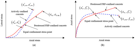
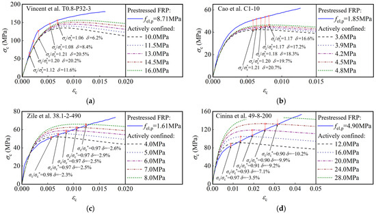
Figure 1 compares the typical lateral strain–axial strain relationships and axial stress–strain curves of actively confined concrete and prestressed FRP-confined concrete. The curves of prestressed FRP-confined concrete are obtained from the experimental results reported in Ref. [18], whereas the curves of actively confined concrete are generated using the aforementioned actively confined concrete model.
Figure 1.
Comparison of typical curves for actively confined concrete and prestressed FRP-confined concrete: (a) Lateral strain–axial strain relationship. (b) Axial stress–strain curve.
As shown in Figure 1, the failure state of actively confined concrete is characterized by its peak stress and the corresponding peak strain . In contrast, the ultimate state of prestressed FRP-confined concrete is determined by the compressive strength and the corresponding ultimate axial strain when the FRP jacket reaches its rupture strain .
The comparison indicates that the two confinement systems exhibit different confinement stress paths, resulting in distinct characteristics of their axial stress–strain responses. For actively confined concrete, the stress–strain curve initially exhibits a linear ascending stage under a constant confinement stress, followed by a parabolic stage until reaching the peak stress. After the peak point, the curve gradually decreases. During the descending branch, the residual strength generated by the internal friction of concrete is reflected as a relatively stable stress plateau, namely the residual stress .
In contrast, the stress–strain curve of prestressed FRP-confined concrete exhibits a higher initial stress level in the linear elastic stage due to the existence of initial lateral confinement stress. With increasing axial load, the FRP confinement stress continuously develops, resulting in a transition into a linear hardening stage. Ultimately, the curve reaches the ultimate state due to rupture of the FRP jacket.
3. Development of the Stress–Strain Model
3.1. Stress-Path Dependency
In existing studies on the stress–strain relationship of confined concrete, the stress-path independence assumption is generally adopted, where the influence of different confinement mechanisms and loading paths on the axial stress response is neglected [34]. However, recent investigations have indicated that the stress–strain response of confined concrete may depend on the stress path [41,42,43].
Li et al. [42] reported that the stress-path dependency of FRP-confined concrete was insignificant under monotonic loading, whereas it became more pronounced under cyclic loading. Through comparative analyses of experimental data, Lim et al. [43] found that, under identical axial strain and confinement stress conditions, the axial stress of FRP-confined concrete was generally lower than that of actively confined concrete. This observation indicates that the axial stress response is influenced by the loading path of confinement pressure, and this phenomenon is particularly evident in high-strength concrete. Similar conclusions were obtained by Lai et al. [41], who incorporated the influence of stress path by introducing a confinement pressure gradient prediction equation and a modified peak stress formulation.
As discussed above, under monotonic axial compression, particularly for FRP-confined high-strength concrete, the axial stress–strain response exhibits a certain degree of stress-path dependency. Unlike actively confined concrete, where the confinement pressure remains constant, the confinement stress in FRP-confined concrete gradually develops with increasing deformation. Therefore, at the same axial stress level, actively confined concrete generally exhibits a higher axial stiffness and hence a smaller axial strain than FRP-confined concrete, which is associated with the slower development of internal cracking under sustained confinement [44,45]. In other words, under identical axial strain and confinement stress conditions, the axial stress of FRP-confined concrete tends to be lower than that of actively confined concrete.
For the prestressed FRP-confined concrete investigated in this study, the confinement mechanism exhibits distinctive characteristics. At the initial stage of loading, the prestressed FRP provides an initial lateral confinement stress, which enhances the axial stiffness of the core concrete. With increasing axial load, the confinement stress progressively increases due to the development of internal cracking and accelerated lateral dilation of concrete, resulting in continuous changes in axial stiffness. Therefore, the confinement mechanism can be regarded as a transition from an initial state with certain active confinement characteristics toward a passive confinement state.
To establish a more accurate analytical model for prestressed FRP-confined concrete based on actively confined concrete models, the applicability of the stress-path independence assumption must first be examined under such conditions.
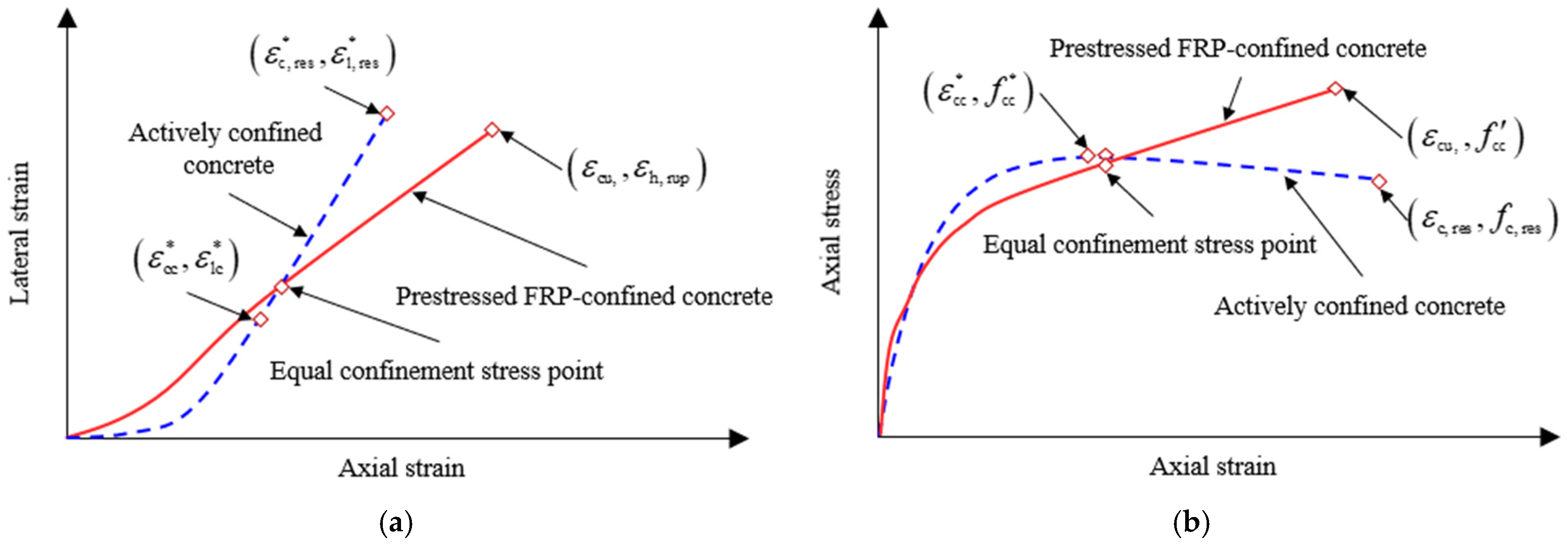
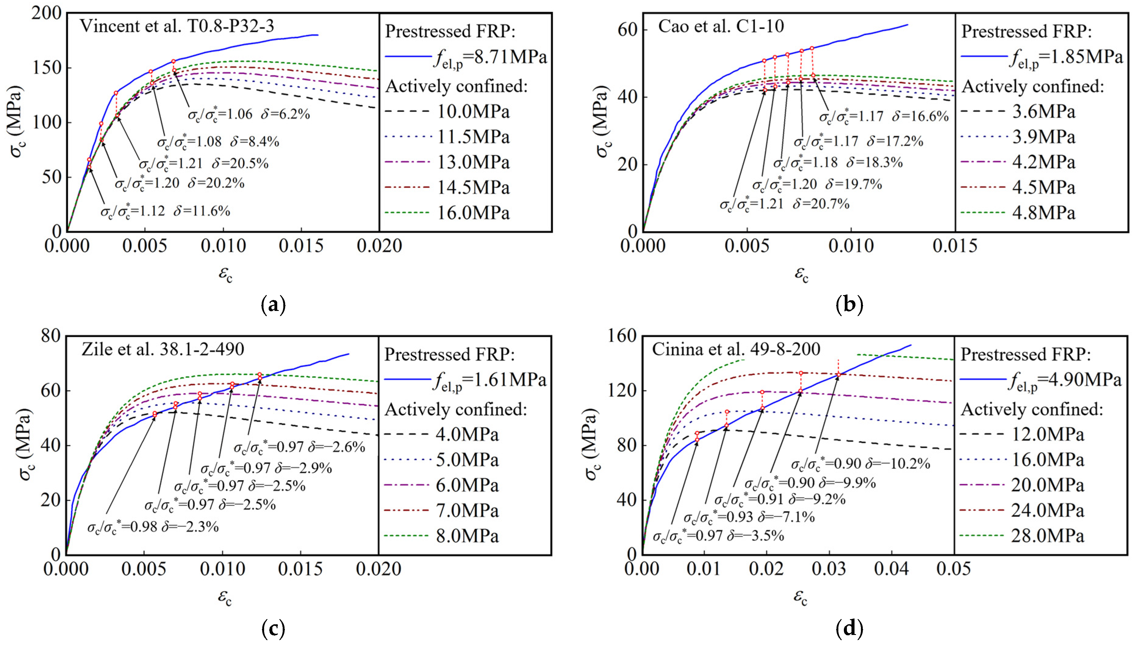
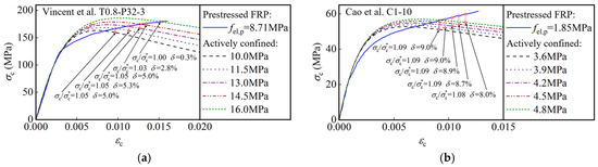
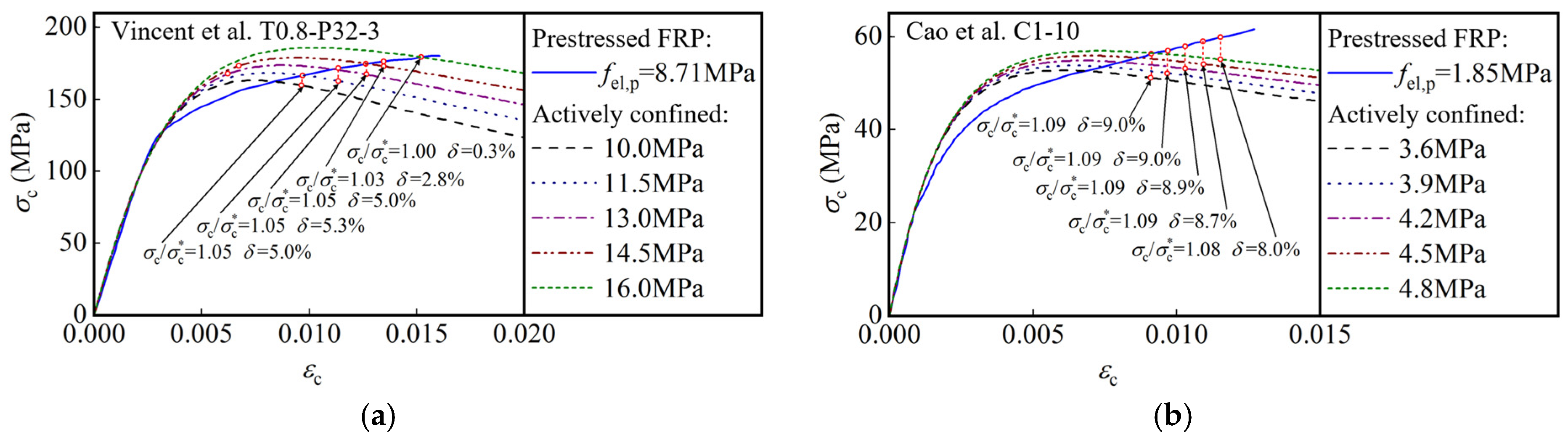
Accordingly, the stress-path independence assumption was evaluated by comparing the curves predicted by actively confined concrete models with experimental stress–strain curves of prestressed FRP-confined concrete. Axial stress–strain test data of prestressed FRP-confined concrete reported in Refs. [18,19,25,26] were selected (solid lines in Figure 2a–d) and compared with a series of curves generated using the actively confined concrete equations (Equations (7), (8), (11) and (12)) (dashed lines). The corresponding axial stress points under identical axial strain and confinement stress conditions were marked in the figures and connected by dashed lines.
Figure 2.
Comparison of axial stress–strain curves for actively confined concrete and prestressed FRP-confined concrete: (a) Vincent et al., specimen T0.8-P32-3; (b) Cao et al., specimen C1-10; (c) Zile et al., specimen 38.1-2-490; (d) Cinina et al., specimen 49-8-200.
The differences between the two responses were quantified using the axial stress ratio and relative error , where represents the experimental axial stress of prestressed FRP-confined concrete and represents the prediction from the actively confined concrete model.
Figure 2a,b present the experimental results obtained using the expansive concrete method, whereas Figure 2c,d show the results obtained using the continuous filament winding method. Different prestressing techniques lead to distinct mechanical responses of confined concrete.
For the expansive concrete method, the measured axial stress is generally higher than the prediction from the actively confined concrete model under identical confinement stress conditions. The axial stress ratio is approximately 1.2, corresponding to a relative error close to 20%. This indicates that the stress–strain response exhibits considerable dependency on the loading path.
In contrast, the results obtained using the continuous filament winding method show that the measured axial stress is generally consistent with the prediction of the actively confined concrete model under equivalent conditions. The axial stress ratio approaches unity, and the relative error is mostly within 10%. Thus, the stress-path dependency of prestressed FRP-confined concrete is closely associated with the prestressing technique.
For the continuous filament winding method, the results satisfy the stress-path independence assumption, indicating that the axial stress–strain response is primarily governed by the instantaneous confinement stress state rather than the loading path used to reach that state.
For the expansive concrete method, however, the measured axial stress exceeds the prediction from the actively confined concrete model, indicating that the stress-path independence assumption cannot be directly applied. This difference can be attributed to the initial confinement state generated by the interaction between the expansive concrete and the surrounding FRP. Specifically, the expansion of the concrete core is restrained by the FRP, inducing hoop tensile stress in the FRP and, in turn, an initial lateral confinement stress in the concrete before external axial loading. The concrete core therefore enters axial loading from an initially confined triaxial compressive stress state rather than an unconfined state. This initial confinement restrains lateral dilation and delays the development of internal microcracking, thereby maintaining a higher axial stress level during the transition from the initial ascending stage to the nonlinear stage. Consequently, the transition stress of prestressed FRP-confined concrete is governed not only by the properties of the unconfined concrete but also by the initial lateral confinement generated by FRP prestressing.
For prestressed FRP-confined concrete, the initial lateral confinement stress generated by the FRP prestress strain can be calculated using Equation (13).
Therefore, unlike unconfined concrete, the transition from the elastic stage to the nonlinear stage of prestressed FRP-confined concrete is not solely governed by the unconfined concrete strength . The influence of the initial lateral confinement stress on the elastic-limit state should also be considered.
For conventional FRP-confined concrete, the confinement action is passive and develops progressively with lateral dilation. For sufficiently confined specimens exhibiting the typical bilinear stress–strain response, Lam et al. [46] reported that the ratio of the stress-axis intercept obtained by backward extrapolation of the approximately linear second branch to the unconfined concrete compressive strength ranges from 1.0 to 1.2, with an average value of approximately 1.09. Thus, provides a reasonable reference stress for characterizing the transition region of such conventional FRP-confined concrete. For prestressed FRP-confined concrete produced using the expansive concrete method, however, an initial lateral confinement stress already exists before axial loading. The corresponding reference stress should therefore be modified to account for the influence of .
Previous studies [26,28,47] have indicated that when the axial stress approaches the unconfined concrete compressive strength , the development of internal microcracks activates the lateral confinement provided by FRP, causing the stress–strain curve to enter the nonlinear stage. Therefore, it is assumed that the boundary of the elastic stage of confined concrete is controlled by the development of microcracks, and the lateral strain of concrete at this point is equal to the lateral strain of unconfined concrete corresponding to , where .
Based on Hooke’s law, the axial stress corresponding to the elastic limit under the initial lateral confinement stress can be derived as Equation (14). The Poisson’s ratio is calculated using the equation proposed by Candappa [48].
The parameter represents the axial stress corresponding to the elastic limit state under the initial lateral confinement condition, rather than an additional axial stress applied to the concrete core.
To incorporate the influence of the initial lateral confinement stress into the actively confined concrete model, and its corresponding axial strain are used to replace and , respectively, in the equations for calculating the peak stress and peak strain . The modified formulations are expressed as Equations (15) and (16).
where the axial strain corresponding to is calculated using (unit: MPa) proposed by Popovics [37].
Figure 3 compares the modified actively confined concrete model with the experimental stress–strain curves of prestressed FRP-confined concrete. Specifically, after modification, the axial stress ratio approaches unity and the relative error remains generally within 10%, demonstrating a substantial reduction in the discrepancy between the actively confined concrete model and the experimental response. The modified model therefore provides a reasonable representation of the axial stress–strain response within the range of the available validation data.
Figure 3.
Comparison of axial stress–strain curves for improved actively confined concrete and prestressed FRP-confined concrete: (a) Vincent et al., specimen T0.8-P32-3; (b) Cao et al., specimen C1-10.
3.2. Strain-Path Dependency
In analytical models for non-prestressed FRP-confined concrete, the strain-path independence assumption is generally adopted [34,43]. This assumption indicates that actively confined concrete and FRP-confined concrete exhibit identical lateral strains under the same axial strain and confinement stress conditions.
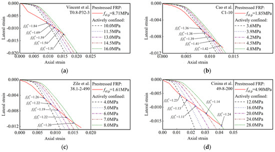
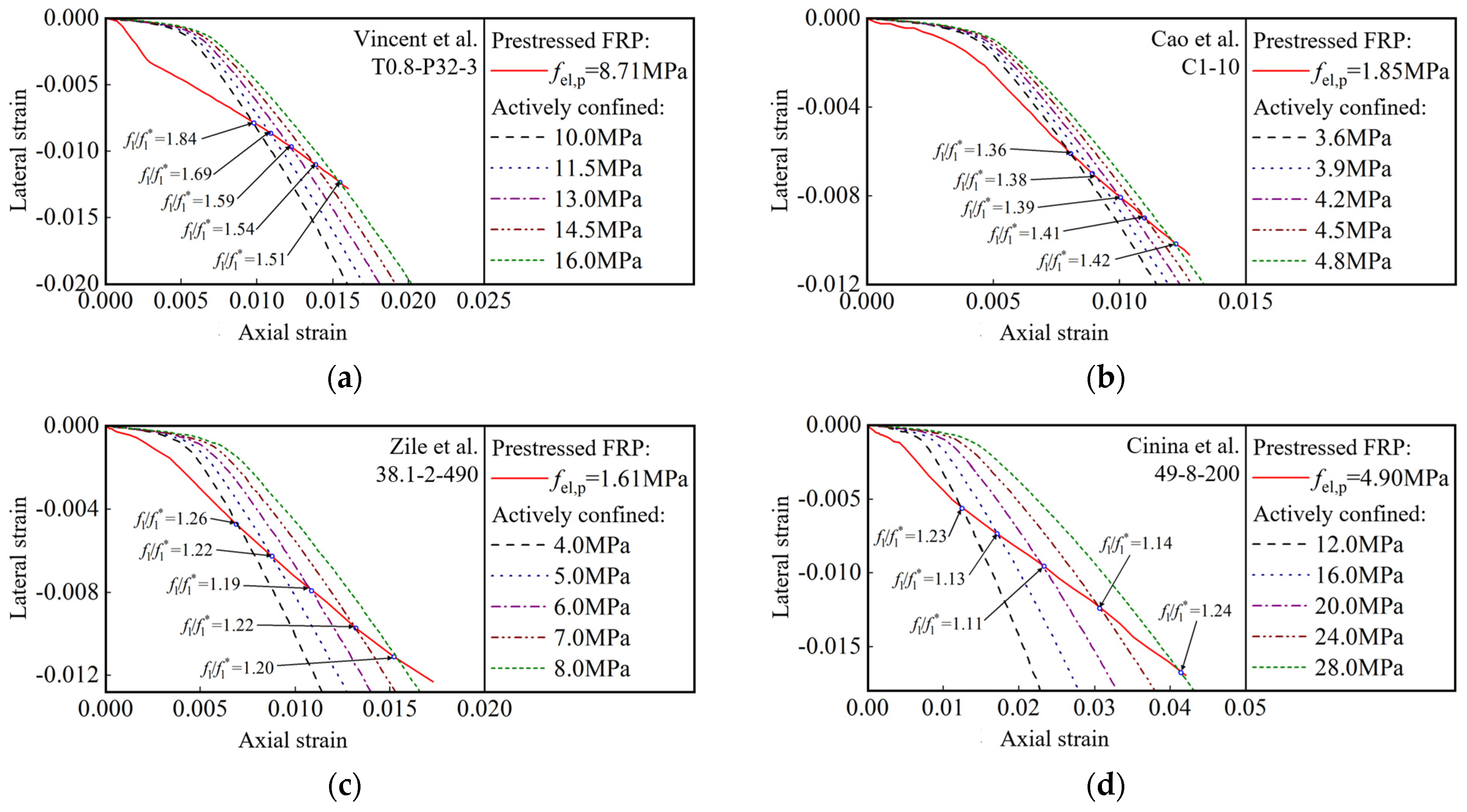
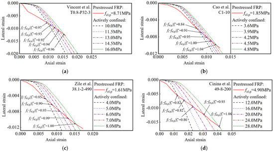
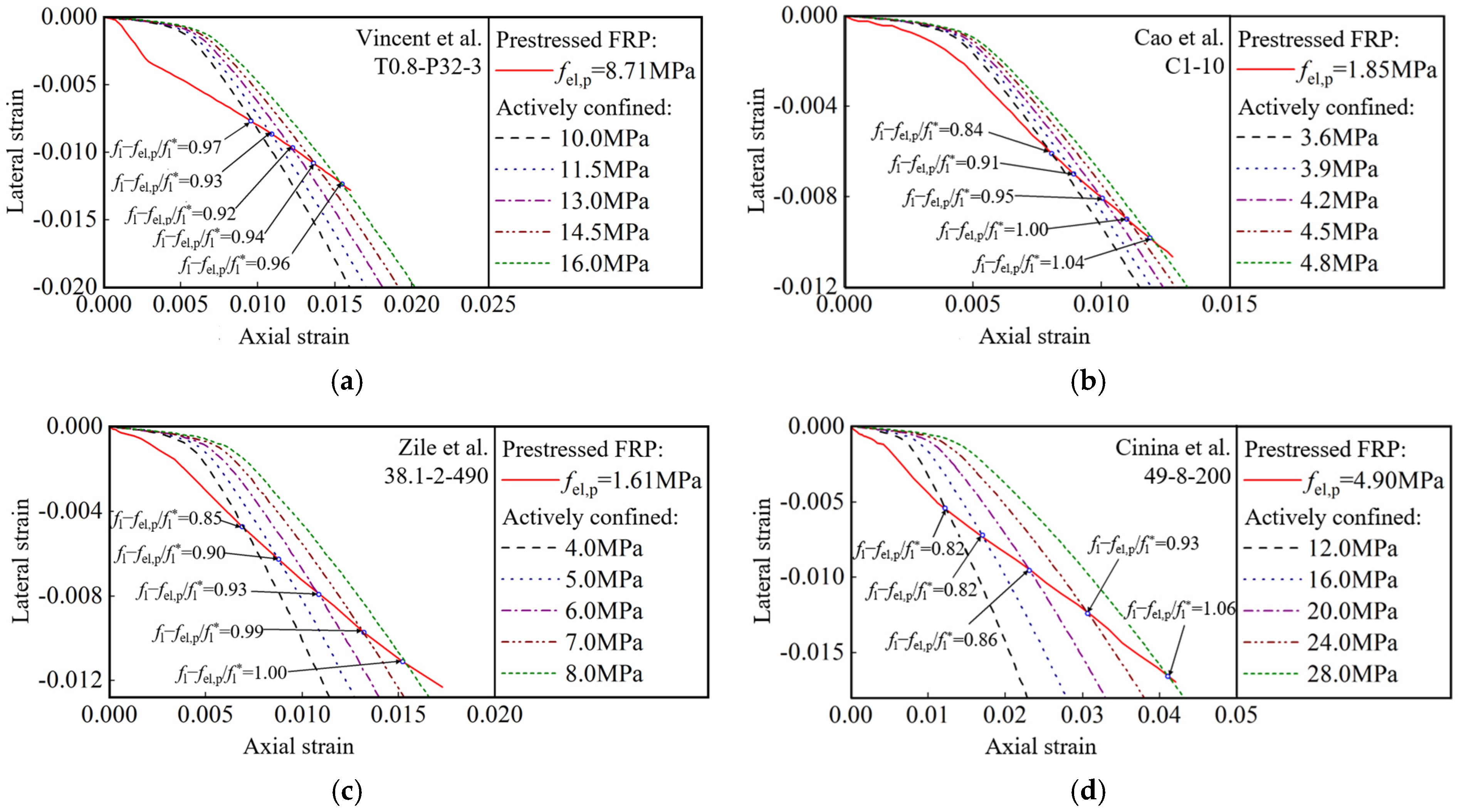
To evaluate the applicability of this assumption to prestressed FRP-confined concrete, Figure 4 compares the lateral strain–axial strain relationships obtained from prestressed FRP-confined concrete tests reported in Refs. [18,19,25,26] with those calculated using Equation (3) for actively confined concrete. The solid lines represent the experimental results of prestressed FRP-confined concrete, whereas the dashed lines denote the curves generated from the actively confined concrete model. The intersection points indicate the corresponding confinement stresses under identical axial strain and lateral strain conditions.
Figure 4.
Comparison of lateral strain versus axial strain curves for actively confined concrete and prestressed FRP-confined concrete: (a) Vincent et al., specimen T0.8-P32-3; (b) Cao et al., specimen C1-10; (c) Zile et al., specimen 38.1-2-490; (d) Cinina et al., specimen 49-8-200.
The difference between the two responses is quantified by the confinement stress ratio , where represents the confinement stress of prestressed FRP-confined concrete and represents that of actively confined concrete. A confinement stress ratio close to unity indicates that the strain-path independence assumption is satisfied.
Figure 4a,b present the results obtained using the expansive concrete method, whereas Figure 4c,d correspond to the continuous filament winding method. It can be observed that, under the initial reference condition, the lateral strain–axial strain relationships of the two confinement systems intersect successively as the confinement stress increases. The confinement stress ratios at these intersection points are relatively large, indicating that the strain-path independence assumption is not directly applicable.
Considering the influence of the initial lateral confinement stress in prestressed FRP-confined concrete, Figure 5 presents the modified comparison curves, where the initial strain component corresponding to is subtracted from the lateral strain of prestressed FRP-confined concrete. After this modification, the confinement stress ratios at the intersection points approach unity, indicating a strong consistency between the two relationships and confirming the existence of strain-path dependency.
Figure 5.
Comparison of lateral strain versus axial strain curves for modified actively confined concrete and prestressed FRP-confined concrete: (a) Vincent et al., specimen T0.8-P32-3; (b) Cao et al., specimen C1-10; (c) Zile et al., specimen 38.1-2-490; (d) Cinina et al., specimen 49-8-200.
Therefore, to accurately describe the deformation behavior of prestressed FRP-confined concrete, the influence of the initial lateral confinement stress should be incorporated into the lateral strain–axial strain relationship. Accordingly, Equation (3) is modified, resulting in Equation (17).
3.3. Generation of Stress–Strain Curves
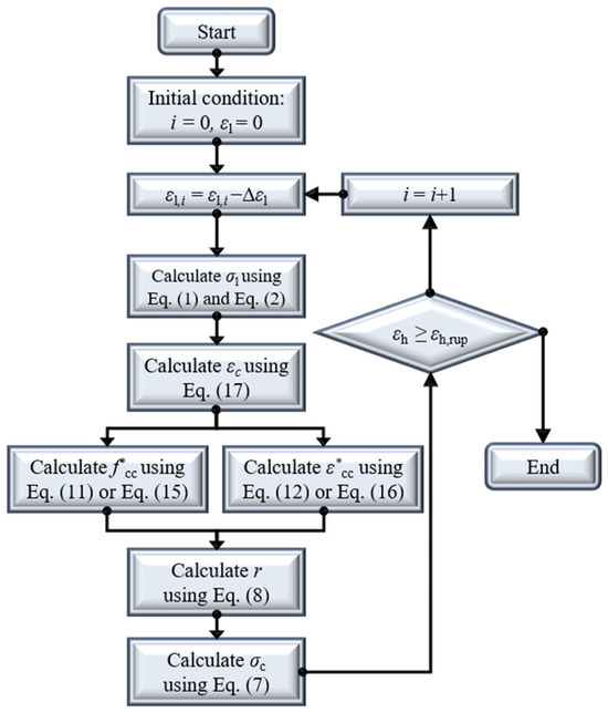
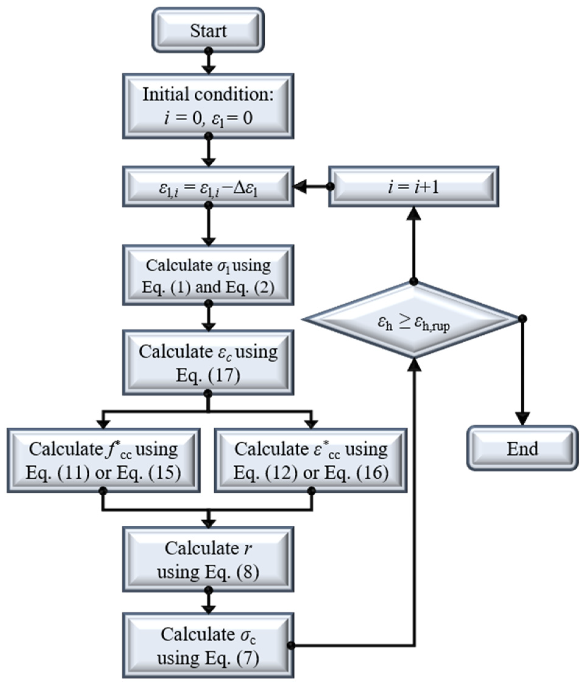
The axial stress, confinement stress, axial strain, and lateral strain of prestressed FRP-confined concrete are interrelated; therefore, the complete stress–strain response is generated through a strain-controlled incremental calculation procedure. Based on the preceding analyses of stress-path and strain-path dependency, Figure 6 presents the corresponding calculation framework. The calculation starts from and . At each step, the lateral strain is incremented by a prescribed magnitude , and the corresponding FRP hoop strain and confinement stress are determined using Equations (1) and (2). The axial strain is subsequently obtained from Equation (17), followed by the peak stress and peak strain from Equations (15) and (16), respectively. The parameter and the corresponding axial stress are then calculated using Equations (7) and (8). This procedure is repeated until the FRP hoop strain reaches , with the final increment adjusted such that the rupture strain is reached exactly.
Figure 6.
Flowchart of the strain-controlled incremental calculation procedure for the stress–strain analytical model of prestressed FRP-confined concrete.
A step-size sensitivity assessment was conducted using , , , , , and , with the result obtained using taken as the reference. The stress deviation was normalized by the ultimate stress of the reference solution. The discretization error increased progressively as the strain increment was enlarged. At , the maximum normalized stress deviation over the complete stress–strain response was approximately 0.54%, while the normalized stress deviation at the transition stage was approximately 0.05%, indicating that the transition response remained adequately resolved. When the increment was increased to , the maximum deviation over the complete response increased to approximately 2.17%, with further increases in the increment noticeably reducing the resolution of the predicted curve. Accordingly, for the representative case examined, was identified as a practical upper bound for maintaining adequate numerical resolution and discretization accuracy. A more conservative increment of was adopted in the subsequent calculations and resulted in a maximum normalized stress deviation of only approximately 0.00023% relative to the reference solution. The final increment was adjusted such that the FRP hoop strain reached its rupture strain exactly, thereby avoiding step-size-induced truncation of the ultimate state. Because the state variables at each increment are evaluated directly from the corresponding analytical expressions rather than through a nonlinear equilibrium iteration, no convergence-tolerance parameter is required.
3.4. Parameter Sensitivity Analysis
A parameter sensitivity analysis was conducted to quantify the effects of the principal model inputs on the predicted stress–strain response. The parameters considered were the unconfined concrete compressive strength , FRP elastic modulus , FRP thickness , and prestress strain ratio . Each parameter was first varied individually over a representative range while the remaining model inputs were held at their reference values. To allow direct comparison among parameters with different dimensions and magnitudes, a normalized local sensitivity coefficient was further evaluated using a perturbation about the reference state:
where and denote the reference input and corresponding model response, respectively; and ; and are the corresponding predicted responses. A positive coefficient indicates that the response changes in the same direction as the input parameter, whereas a negative coefficient indicates an inverse relationship; the absolute magnitude represents the local relative sensitivity. The ultimate confinement ratio was additionally considered as a derived parameter, defined as , where is the lateral confinement stress corresponding to FRP hoop rupture. For this assessment, , , and were held constant, while was varied such that ranged from 0.25 to 0.45.
The results show that and have identical local sensitivities, with coefficients of 0.606 for ultimate compressive strength and 0.719 for ultimate axial strain. This result is consistent with the confinement relationship, in which both parameters act through the product when the specimen diameter is fixed. Increasing increases the predicted ultimate compressive strength but reduces the ultimate axial strain, with corresponding sensitivity coefficients of 0.380 and −0.600. Under unchanged FRP confinement, the increase in concrete strength reduces the relative confinement level and consequently weakens the confinement-induced enhancement of deformation capacity. The ultimate confinement ratio exhibits a stronger influence on deformation than on strength, with sensitivity coefficients of 1.381 and 0.460 for ultimate axial strain and ultimate compressive strength, respectively. As increases from 0.25 to 0.45, the ultimate compressive strength varies from approximately −14.3% to +11.2% relative to the reference case, whereas the corresponding variation in ultimate axial strain ranges from approximately −39.1% to +35.9%.
The prestress strain ratio produces different effects on the strength and deformation responses. Its normalized sensitivity coefficients are 0.093 for ultimate compressive strength and −0.162 for ultimate axial strain, indicating an increase in strength accompanied by a reduction in ultimate deformation as the prestress level increases. Over the investigated range of , the predicted ultimate compressive strength varies from approximately −9.1% to +20.0% relative to the reference case at , whereas the ultimate axial strain varies from approximately +16.7% to −30.3%. This opposite trend follows directly from the confinement mechanism represented in the model. Increasing increases the FRP prestress strain and hence the initial lateral confinement stress , resulting in a higher axial stress level. At the same time, for a given hoop rupture strain , a larger reduces the remaining hoop-strain reserve available during subsequent axial loading, thereby reducing the deformation that can develop before FRP rupture. Overall, the sensitivity results indicate that FRP confinement stiffness and the ultimate confinement level strongly affect the confinement-induced strength and deformation enhancement, while the prestress level modifies the balance between the initial confinement effect and the remaining deformation capacity of the FRP.
4. Model Validation
To evaluate the applicability of the proposed analytical model, experimental data for prestressed FRP-confined concrete reported in Refs. [18,19,25,26,49] were collected for validation. A summary of the experimental database is provided in Table 1. The database includes carbon fiber-reinforced polymer (CFRP), glass fiber-reinforced polymer (GFRP), basalt fiber-reinforced polymer (BFRP), and aramid fiber-reinforced polymer (AFRP) confinement systems. According to the prestressing method, the specimens were grouped into two categories: the self-stressing method using expansive concrete (EC) and the prestressed FRP filament winding method (PW). The unconfined concrete compressive strengths from 12.3 to 110.3 MPa, the FRP elastic modulus from 34,700 to 236,000 MPa, the FRP thicknesses from 0.167 to 1.58 mm, hoop rupture strains from 0.0114 to 0.0220, and prestress strain ratios from 0 to 32.32%.
Table 1.
Summary of experimental database used for model validation.
The broad parameter coverage in this database not only reflects significant heterogeneity in test conditions across different FRP systems and prestressing methods but also makes such scatter particularly valuable for evaluating the robustness and generalizability of the proposed analytical model. The combination of different FRP materials, confinement stiffness levels, and prestress levels enables the model to be examined over a broader parameter space in terms of compressive-strength enhancement, lateral confinement effects, and deformation evolution, thereby reducing the risk that the validation is dominated by a single material system or a specific prestressing condition. Consequently, the database provides a reasonably representative basis for assessing the applicability of the proposed model within the range of currently available experimental evidence.
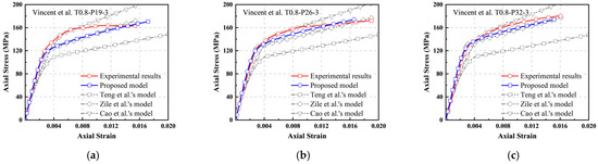
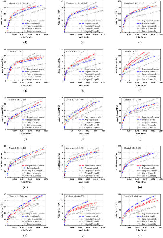
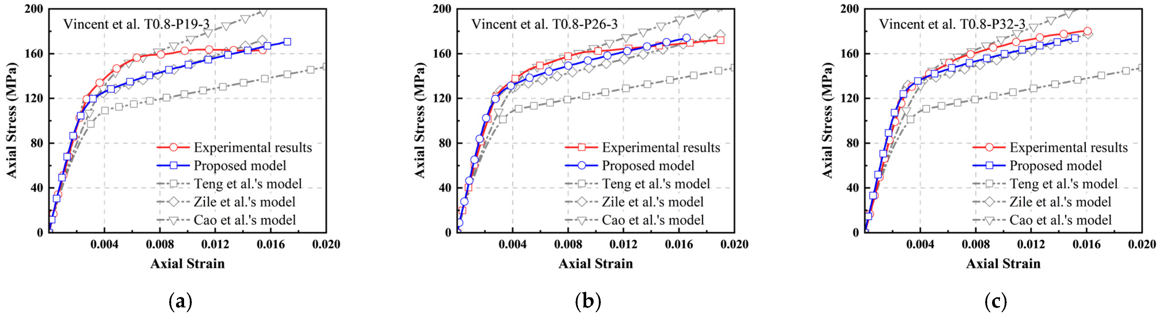
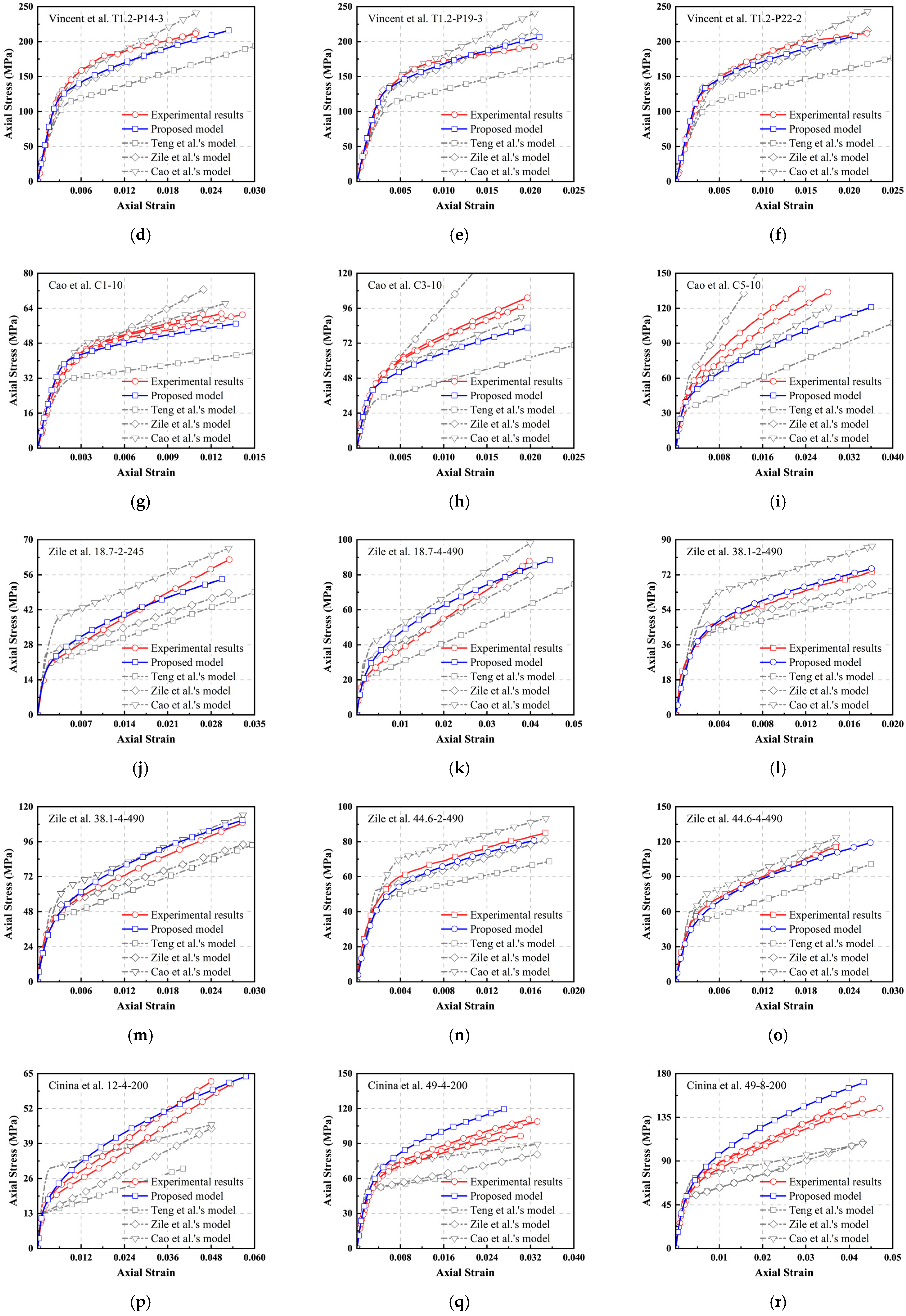
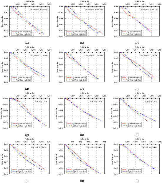
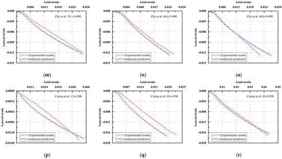
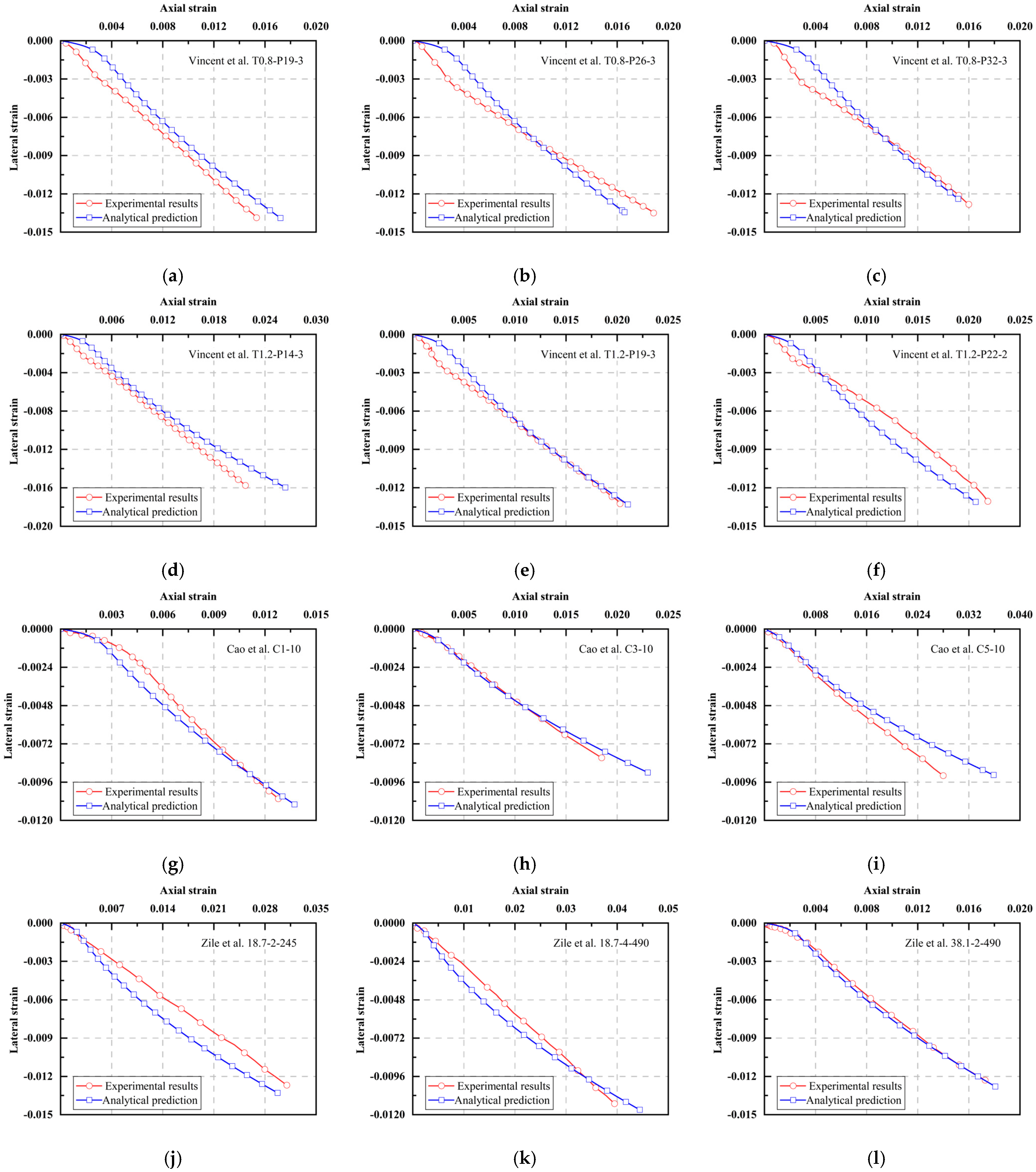
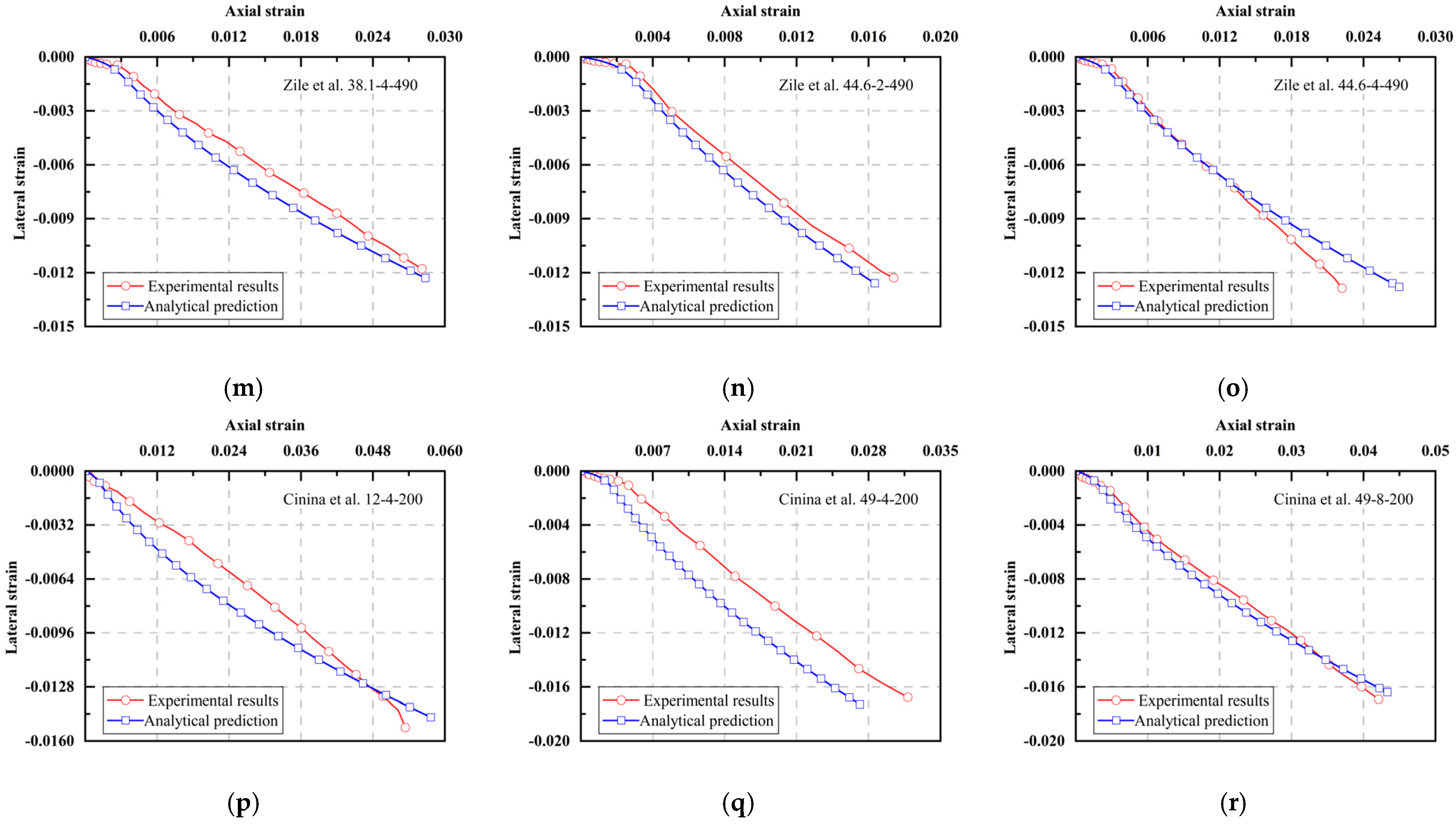
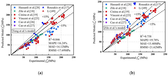
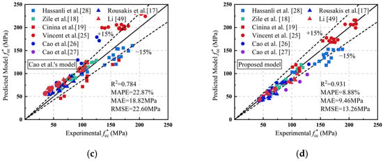
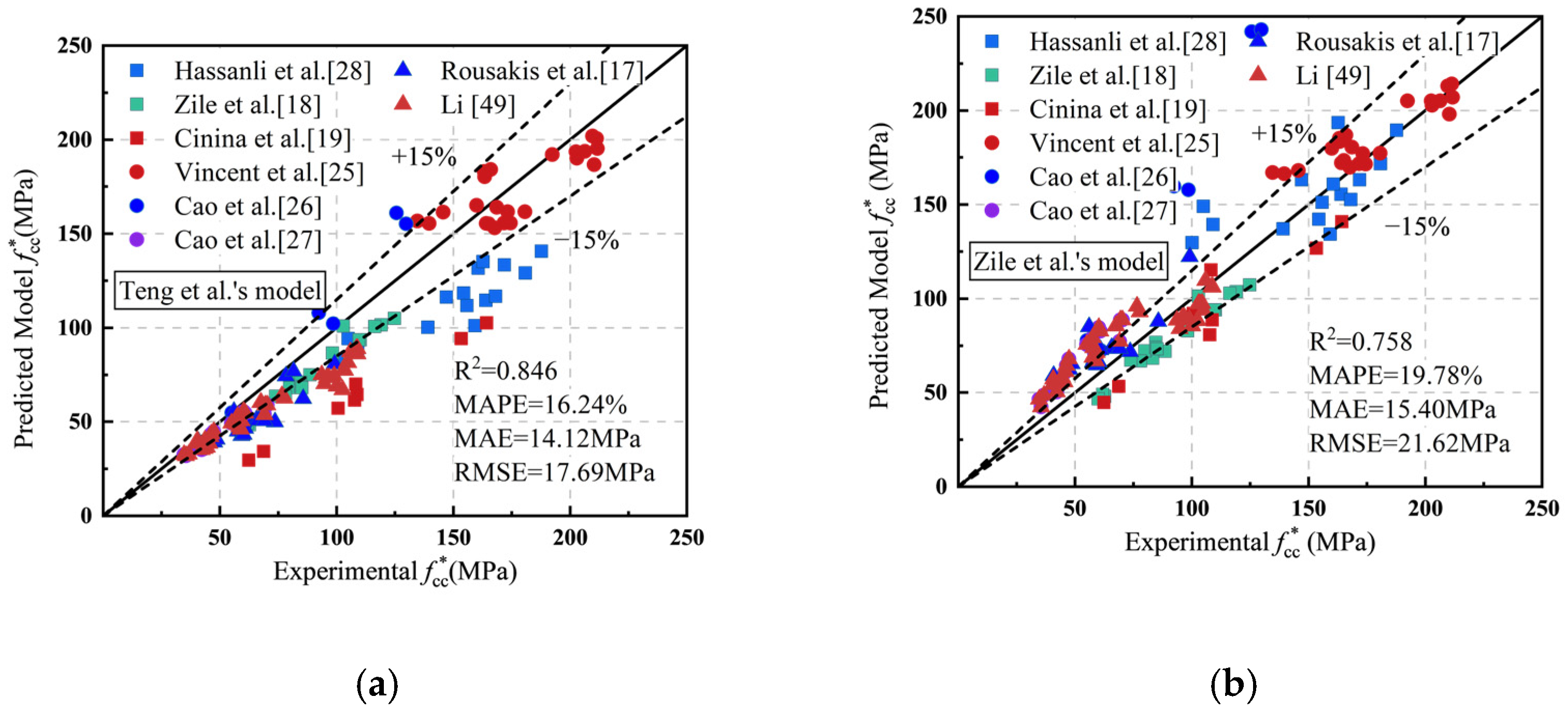
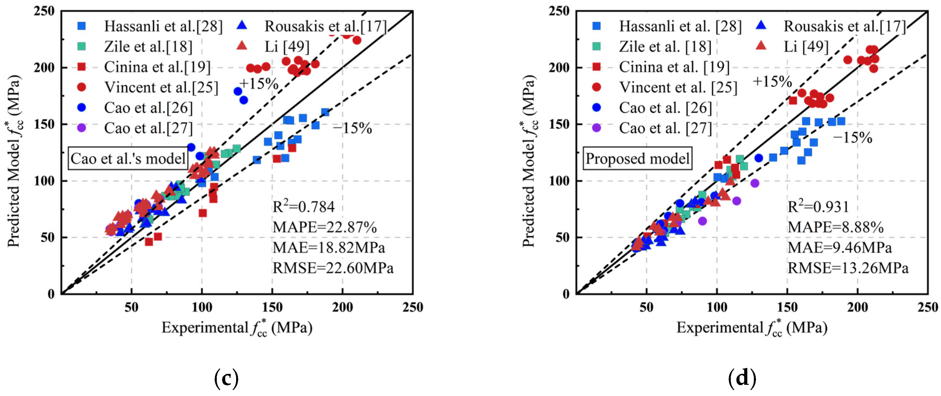
Figure 7 compares the axial stress–strain curves predicted by the proposed model and three existing analytical models with the corresponding experimental results. The model proposed by Teng et al. [34] is a classical analysis-oriented model for FRP-confined concrete and has been widely adopted in subsequent studies. Sadeghian and Fam [50] systematically evaluated existing analytical models using an established database of FRP-confined concrete cylinders and reported good predictive performance for the model of Teng et al. This model was therefore included in the comparison to examine the applicability of an existing model for conventional FRP-confined concrete under prestressed conditions. Zile et al. [18] and Cao et al. [26,27] developed analytical models for prestressed FRP-confined concrete based on axial compression tests of specimens prestressed using the PW and EC methods, respectively. Figure 8 compares the lateral strain–axial strain relationships predicted by the proposed model with the experimental results. Figure 9 further provides a quantitative assessment of the compressive-strength predictions of the proposed and existing models using the same experimental database and four consistent statistical indicators.
Figure 7.
Comparison of axial stress–strain curves predicted by the proposed and existing analytical models with experimental results: (a) Vincent et al., specimen T0.8-P19-3; (b) Vincent et al., specimen T0.8-P26-3; (c) Vincent et al., specimen T0.8-P32-3; (d) Vincent et al., specimen T1.2-P14-3; (e) Vincent et al., specimen T1.2-P19-3; (f) Vincent et al., specimen T1.2-P22-2; (g) Cao et al., specimen C1-10; (h) Cao et al., specimen C3-10; (i) Cao et al., specimen C5-10; (j) Zile et al., specimen 18.7-2-245; (k) Zile et al., specimen 18.7-4-490; (l) Zile et al., specimen 38.1-2-490; (m) Zile et al., specimen 38.1-4-490; (n) Zile et al., specimen 44.6-2-490; (o) Zile et al., specimen 44.6-4-490; (p) Cinina et al., specimen 12-4-200; (q) Cinina et al., specimen 49-4-200; (r) Cinina et al., specimen 49-8-200.
Figure 8.
Comparison of predicted and experimental lateral strain–axial strain relationships: (a) Vincent et al., specimen T0.8-P19-3; (b) Vincent et al., specimen T0.8-P26-3; (c) Vincent et al., specimen T0.8-P32-3; (d) Vincent et al., specimen T1.2-P14-3; (e) Vincent et al., specimen T1.2-P19-3; (f) Vincent et al., specimen T1.2-P22-2; (g) Cao et al., specimen C1-10; (h) Cao et al., specimen C3-10; (i) Cao et al., specimen C5-10; (j) Zile et al., specimen 18.7-2-245; (k) Zile et al., specimen 18.7-4-490; (l) Zile et al., specimen 38.1-2-490; (m) Zile et al., specimen 38.1-4-490; (n) Zile et al., specimen 44.6-2-490; (o) Zile et al., specimen 44.6-4-490; (p) Cinina et al., specimen 12-4-200; (q) Cinina et al., specimen 49-4-200; (r) Cinina et al., specimen 49-8-200.
Figure 9.
Comparison of experimental and predicted compressive strengths [18,19,25,26,27,28]: (a) Teng et al.’s model; (b) Zile et al.’s model; (c) Cao et al.’s model; and (d) proposed model.
4.1. Axial Stress–Strain Curves
To examine the ability of different models to predict the complete axial stress–strain response, predictions obtained using the same specimen parameters were compared with the corresponding experimental results, as shown in Figure 7.
The model of Teng et al. was originally developed for FRP-confined concrete without considering initial prestress in the FRP. For the various prestressed specimens considered in Figure 7, the predicted transition region and ultimate stress are generally lower than the experimental results, and the second branches of the predicted curves lie noticeably below the measured curves. In addition, the model markedly overestimates the ultimate axial strains of the specimens tested by Zile et al., Vincent et al., and Cao et al. Given the good predictive performance of this model for non-prestressed FRP-confined concrete, the axial response of non-prestressed specimens with comparable concrete strength and FRP confinement stiffness may reasonably be expected to be close to its predictions. The discrepancies observed here therefore indicate that prestressing increases the ultimate compressive strength while reducing the ultimate axial strain, thereby altering the axial compressive response from that of conventional FRP-confined concrete. Consequently, analytical models developed for non-prestressed FRP-confined concrete cannot be directly extended to prestressed conditions and are insufficient to describe the complete stress–strain response of prestressed FRP-confined concrete.
Unlike the Teng et al. model, the models of Zile et al. and Cao et al., which were specifically developed for prestressed conditions, do not systematically underestimate the stress response. Both models provide good predictions for their own experimental data because their ultimate-state relationships were established from the corresponding prestressed-concrete tests. However, their prediction accuracy decreases when they are applied to independent experimental datasets. The Zile et al. model provides reasonable predictions for the Vincent et al. specimens but generally underestimates the stress response of the Cinina et al. specimens. The Cao et al. model overestimates the responses of the Vincent et al. specimens and some of the Zile et al. specimens, while underestimating those of some Cinina et al. specimens. The accurate prediction ranges of the two models remain closely related to the experimental domains on which they were developed, and deviations emerge when they are applied to different prestressing methods or FRP types.
It should be noted that Cao et al. did not report the actual hoop rupture strain of GFRP for each specimen, but only provided the ultimate rupture strain of the GFRP and stated that all specimens failed by GFRP rupture. Accordingly, the material ultimate rupture strain was adopted as the hoop rupture strain in the model calculations for the Cao et al. specimens. However, the actual hoop rupture strain developed in confined specimens is generally lower than the material ultimate value. This difference may explain the deviations observed in the predictions of the Zile et al. model and the proposed model for these specimens.
Compared with the existing models, the proposed model provides a more consistent description of the overall axial stress–strain response across different experimental datasets. Except for the deviations observed for the Cao et al. specimens and the slight overestimation of the second ascending branch for Cinina et al. specimens 49-4-200 and 49-8-200, the predicted curves agree well with the experimental results for different FRP types and prestressing methods. The transition from the initial nonlinear response to the second ascending branch and the subsequent stress development are reasonably reproduced within the range covered by the database, with no systematic bias associated with a particular FRP type or prestressing method.
Overall, within the database examined, the proposed model consistently describes the complete stress–strain response of prestressed FRP-confined concrete under different confinement systems, although some limitations remain for the low-elastic-modulus BFRP specimens reported by Cinina et al. The complete constitutive relationship governs the evolution of material stiffness and axial deformation throughout loading. The proposed model shows consistent applicability across different prestressing methods and FRP materials, thereby addressing the limited applicability of existing models to prestressed FRP-confined concrete. It therefore provides a practical constitutive input for nonlinear analysis and a quantitative tool for subsequent engineering design and safety assessment.
4.2. Lateral Strain–Axial Strain Curves
To evaluate the lateral deformation predicted by the modified strain relationship, the calculated lateral strain–axial strain curves were compared with the experimental results, as shown in Figure 8. Overall, the proposed model reproduces the measured development of lateral strain for specimens prestressed using both the EC and PW methods. The predicted curves capture the relatively slow lateral expansion at small axial strains and the subsequent increase in lateral dilation as axial compression proceeds. The agreement supports the strain-path modification introduced in Section 3.2, in which the initial strain component associated with FRP prestress is accounted for in the lateral strain–axial strain relationship.
The lateral strain prediction is directly related to the confinement stress through the deformation compatibility between the concrete and FRP. Therefore, the agreement shown in Figure 8 also indicates that the model reasonably captures the evolution of FRP confinement during axial loading. This provides the deformation basis required for calculating the complete axial stress–strain response of prestressed FRP-confined concrete.
4.3. Compressive Strength
To quantitatively evaluate the predictive capability of the proposed model for the compressive strength of prestressed FRP-confined concrete, the coefficient of determination (R2), mean absolute percentage error (MAPE), mean absolute error (MAE), and root mean square error (RMSE) were adopted to assess the agreement between the predicted and experimental values. The corresponding statistical indices are calculated by Equations (19)–(22).
In these equations, is the experimental compressive strength of the i-th specimen, is the corresponding predicted value, is the mean value of all experimental results, and is the total number of specimens. R2 measures the proportion of variance in the experimental data explained by the model; MAPE reflects the average relative prediction error; MAE represents the average absolute deviation while retaining the engineering unit of compressive strength; and RMSE is more sensitive to relatively large errors and is used to characterize the overall dispersion of the prediction error. A model with an R2 value closer to unity and lower MAPE, MAE, and RMSE values indicates better agreement with the experimental data.
Figure 9 compares the predicted compressive strengths with the experimental results. Most data points are distributed around the 45° reference line and fall within the ±15% error band, indicating the absence of significant systematic bias. The proposed model achieved an R2 of 0.931 and a MAPE of 8.88%, demonstrating its ability to capture the variation in compressive strength under different prestressing methods and FRP types, with an average relative prediction error below 10%. The MAE was 9.46 MPa, indicating an average absolute deviation of 9.46 MPa between the predicted and experimental strengths. The RMSE was 13.26 MPa, which was higher than the MAE, suggesting that relatively large prediction errors contributed to the overall error level; however, no obvious abnormal deviation was observed in the scatter distribution. Taken together, the statistical indices and scatter distribution indicate that the proposed model provides reasonably accurate predictions of compressive strength for the available validation dataset, covering a range of FRP systems and prestressing conditions.
Compressive strength is a key parameter governing the stress–strain response of prestressed FRP-confined concrete, and its prediction accuracy directly affects the evaluation of load-carrying capacity and the determination of subsequent deformation parameters. Based on the currently available validation dataset, the proposed model maintains stable predictive performance over different FRP types, prestress levels, and confinement conditions, indicating good applicability across the range of conditions examined in this study. Therefore, it can serve as a practical analytical tool for load-carrying capacity assessment, full-range nonlinear analysis, and the selection and design of confinement parameters for prestressed FRP-confined concrete members.
5. Conclusions
This study systematically investigated the differences between prestressed FRP-confined circular concrete and actively confined concrete in terms of stress-path and strain-path behavior, and established a unified stress–strain analytical model. The main conclusions are summarized as follows:
- (1)
- The stress-path dependency of prestressed FRP-confined concrete is closely related to the prestressing technique. For the continuous filament winding method, the axial stress–strain response is primarily governed by the instantaneous confinement state, and the stress-path independence assumption can be reasonably adopted. In contrast, expansive methods exhibit apparent path dependency due to the influence of initial lateral confinement on the axial stiffness of concrete. By incorporating the initial confinement effect into the modification of peak parameters, the differences associated with the prestressing methods considered in this study can be represented within a unified analytical framework.
- (2)
- Prestressed FRP-confined concrete possesses an initial lateral confinement stress that cannot be neglected. After accounting for the prestress-induced initial lateral strain, the lateral strain–axial strain relationship shows strong consistency with that of actively confined concrete. Based on this observation, the lateral strain–axial strain relationship was modified to more accurately describe the evolution of lateral dilation under prestressed confinement conditions.
- (3)
- Based on the identified path-dependent mechanisms, a strain-controlled incremental calculation procedure integrating the FRP confinement relationship, modified peak parameter models, and modified lateral strain–axial strain relationship was established. The developed stress–strain model provides a unified description of the relationships among axial stress, axial strain, lateral strain, and confinement stress throughout the entire loading process of prestressed FRP-confined circular concrete.
- (4)
- The proposed model was evaluated using experimental data compiled from published studies. The results show that the model can accurately predict the axial stress–strain response, lateral dilation behavior, and compressive strength of prestressed FRP-confined concrete across the FRP types and prestressing conditions represented in the validation database.
- (5)
- The sensitivity analysis quantifies the effects of concrete strength, FRP elastic modulus and thickness, prestress level, and ultimate confinement ratio on the predicted response. Increasing the prestress level increases the initial confinement and compressive strength but reduces the available FRP hoop-strain reserve before rupture, resulting in a reduction in ultimate axial strain.
- (6)
- Within the validated range, the proposed model is applicable across the prestressing methods and FRP types represented in the validation database. It provides complete axial and lateral responses for nonlinear analysis, while its strength and deformation predictions can support load-carrying-capacity assessment and the determination of prestress levels and FRP confinement parameters in strengthening design.
Author Contributions
Conceptualization, Z.W. and F.H.; methodology, F.H. and Q.M.; software, F.H.; validation, F.H. and Q.M.; formal analysis, F.H.; investigation, F.H.; resources, Z.W.; data curation, F.H.; writing—original draft preparation, F.H. and Q.M.; writing—review and editing, Z.W. and F.H.; visualization, F.H. and Q.M.; supervision, Z.W.; project administration, Z.W.; funding acquisition, Z.W. All authors have read and agreed to the published version of the manuscript.
Funding
This research was funded by the Fujian Provincial Transportation Science and Technology Project (grant number 202118), a technical service project (contract number 2018012201), and a technical service project (contract number 2024091904).
Data Availability Statement
The raw data supporting the conclusions of this article will be made available by the authors on request.
Acknowledgments
The authors gratefully acknowledge Fuzhou University for providing access to academic literature databases and research resources that supported the completion of this study.
Conflicts of Interest
The authors declare that they have no known competing financial interests or personal relationships that could have appeared to influence the work reported in this paper.
Abbreviations
The following abbreviations are used in this manuscript:
| FRP | Fiber-Reinforced Polymer |
| UHPC | Ultra-High-Performance Concrete |
| GFRP-RC | GFRP-Reinforced Concrete |
| CFRP | Carbon Fiber-Reinforced Polymer |
| AFRP | Aramid Fiber-Reinforced Polymer |
| GFRP | Glass Fiber-Reinforced Polymer |
| BFRP | Basalt Fiber-Reinforced Polymer |
| EC | Self-Stressing Method using Expansive Concrete |
| PW | Prestressed FRP Filament Winding Method |
| R2 | Coefficient of Determination |
| MAPE | Mean Absolute Percentage Error |
| MAE | Mean Absolute Error |
| RMSE | Root Mean Squared Error |
References
- Wang, Q.; Liu, X.; Liu, Y.; Liang, X.; Lu, C. Axial stress-strain behavior of pre-stressed CFRP confined concrete columns. Constr. Build. Mater. 2024, 446, 138003. [Google Scholar] [CrossRef] [Scilit]
- Yang, D.; Lin, S.; Zhao, Y.; Yan, X. Stress path-dependent analysis-oriented model for FRP-confined concrete based on equivalent lateral stress. Struct. Concr. 2026, 27, 4763–4781. [Google Scholar] [CrossRef] [Scilit]
- Mohammadi, A.; Shayanfar, J.; Barros, J.A.O. Reliability-Based Design Model for Compressive Strength of Axially Loaded FRP-Confined Concrete Columns. Compos. Struct. 2026, 384, 120159. [Google Scholar] [CrossRef] [Scilit]
- Shayanfar, J.; Barros, J.A.O. Design-Oriented Model of Unified Character to Determine Softening–Hardening Stress–Strain Behavior of FRP-Confined Concrete Columns of General Cross Section. J. Compos. Constr. 2024, 28, 040240772. [Google Scholar] [CrossRef] [Scilit]
- Shayanfar, J.; Barros, J.A.O.; Pereira, J.P.C. A Versatile Model with a Design Framework for Axially-Loaded FRP-Confined Concrete with/without a Stress Reduction-Recovery Behavior. Constr. Build. Mater. 2024, 448, 138097. [Google Scholar] [CrossRef] [Scilit]
- Wang, J.; Xiao, H.; Lu, L.; Yang, J.; Lu, S.; Shayanfar, J. Axial stress-strain model for concrete in partially FRP wrapped reinforced concrete columns. Constr. Build. Mater. 2024, 416, 135028. [Google Scholar] [CrossRef] [Scilit]
- Hu, X.B.; Nie, X.F.; Wang, J.J.; Zhang, S.S. Behavior of FRP spiral-confined concrete under concentric compression. Eng. Struct. 2024, 321, 118898. [Google Scholar] [CrossRef] [Scilit]
- Zeng, J.-J.; Liao, J.-J.; Ye, Y.-Y.; Guo, Y.-C.; Zheng, Y.; Tan, L.-H. Behavior of FRP spiral strip-confined concrete under cyclic axial compression. Constr. Build. Mater. 2021, 295, 123544. [Google Scholar] [CrossRef] [Scilit]
- Ye, Y.-Y.; Zhuge, Y.; Smith, S.T.; Zeng, J.-J.; Bai, Y.-L. Behavior of GFRP-RC columns under axial compression: Assessment of existing models and a new axial load-strain model. J. Build. Eng. 2022, 47, 103782. [Google Scholar] [CrossRef] [Scilit]
- Liao, J.; Zeng, J.-J.; Zheng, Y.; Liu, Y.; Zhuge, Y.; Zhang, L. Constitutive models of ultra-high performance concrete (UHPC) under true tri-axial compression and an analysis-oriented model for FRP-confined UHPC. Eng. Struct. 2024, 305, 117656. [Google Scholar] [CrossRef] [Scilit]
- Zhang, S.; Wang, J.; Lin, G.; Nie, X. Analysis-oriented stress-strain models for ultra-high-performance concrete confined with fiber-reinforced polymer. Engineering 2026, 61, 265–281. [Google Scholar] [CrossRef] [Scilit]
- Zhong, S.; Zhang, L.; Zhu, J. A path-dependent stress-strain model of FRP-confined circular concrete columns derived from an energy balance approach. Eng. Struct. 2024, 321, 118919. [Google Scholar] [CrossRef] [Scilit]
- Shayanfar, J.; Barros, J.A.O.; Rezazadeh, M. Stress-Strain Model for FRP-Confined Circular Concrete Columns Developing Structural Softening Behavior. J. Compos. Constr. 2024, 28, 04023065. [Google Scholar] [CrossRef] [Scilit]
- Mortazavi, A.A.; Pilakoutas, K.; Son, K.S. RC column strengthening by lateral pre-tensioning of FRP. Constr. Build. Mater. 2003, 17, 491–497. [Google Scholar] [CrossRef] [Scilit]
- Yan, Z.; Pantelides, C.P.; Reaveley, L.D. Posttensioned FRP composite shells for concrete confinement. J. Compos. Constr. 2007, 11, 81–90. [Google Scholar] [CrossRef] [Scilit]
- Tamuzs, V.; Tepfers, R.; You, C.S.; Rousakis, T.; Repelis, I.; Skruls, V.; Vilks, U. Behavior of concrete cylinders confined by carbon-composite tapes and prestressed yarns—1. Experimental data. Mech. Compos. Mater. 2006, 42, 13–32. [Google Scholar] [CrossRef] [Scilit]
- Rousakis, T.C.; You, C.-S.; De Lorenzis, L.; Tamužs, V.; Tepfers, R. Concrete Cylinders Confined by Prestressed CFRP Filament Winding under Axial Load. In Proceedings of the 6th International Symposium on Fibre-Reinforced Polymer (FRP) Reinforcement for Concrete Structures (FRPRCS-6), Singapore, 8–10 July 2003; pp. 581–590. [Google Scholar] [CrossRef] [Scilit]
- Zile, E.; Daugevicius, M.; Tamuzs, V. The effect of pretensioned FRP windings on the behavior of concrete columns in axial compression. Mech. Compos. Mater. 2009, 45, 457–466. [Google Scholar] [CrossRef] [Scilit]
- Cinina, I.; Zile, E.; Zile, O. Mechanical behavior of concrete columns confined by basalt FRP windings. Mech. Compos. Mater. 2012, 48, 539–546. [Google Scholar] [CrossRef] [Scilit]
- Yamakawa, T.; Nasrollahzadeh Nesheli, K.; Satoh, H. Seismic or emergency retrofit of RC short columns by use of prestressed aramid fiber belts as external hoops. J. Struct. Constr. Eng. 2001, 66, 135–141. [Google Scholar] [CrossRef] [Scilit] [PubMed]
- Han, S.H.; Hong, K.; Lee, J.B. An experimental study on uniaxial compressive behavior of RC circular columns laterally confined with prestressing aramid fiber strap. J. Korea Concr. Inst. 2009, 21, 159–168. [Google Scholar] [CrossRef] [Scilit][Green Version]
- Qiu, Y.; Zhou, C.; A., S. Analytical Model of Large-Scale Circular Concrete Columns Confined by Pre-Stressed Carbon Fibre Reinforced Polymer Composites under Axial Compression. Struct. Infrastruct. Eng. 2021, 17, 1062–1075. [Google Scholar] [CrossRef] [Scilit]
- Wang, Q.; Song, H.L.; Lu, C.-L.; Zhu, W.X.; Huang, J.Z. Experimental Study of the Relaxation Properties of Carbon Fiber Cloth. Materials 2020, 13, 3603. [Google Scholar] [CrossRef] [Scilit] [PubMed]
- Zhou, C.; Siha, A.; Qiu, Y.; Pan, Q. Experimental investigation of axial compressive behavior of large-scale circular concrete columns confined by prestressed CFRP strips. J. Struct. Eng. 2019, 145, 04019070. [Google Scholar] [CrossRef] [Scilit]
- Vincent, T.; Ozbakkaloglu, T. Compressive behavior of prestressed high-strength concrete-filled aramid FRP tube columns: Experimental observations. J. Compos. Constr. 2015, 19, 04015003. [Google Scholar] [CrossRef] [Scilit]
- Cao, Q.; Tao, J.; Ma, Z.J.; Wu, Z. Axial compressive behavior of CFRP-confined expansive concrete columns. ACI Struct. J. 2017, 114, 475–485. [Google Scholar] [CrossRef] [Scilit][Green Version]
- Cao, Q.; Li, X.; Gao, R. Axial compressive performance of CFRP confined self-stressing high-strength concrete cylinders. KSCE J. Civ. Eng. 2019, 23, 4000–4009. [Google Scholar] [CrossRef] [Scilit]
- Hassanli, R.; Youssf, O.; Vincent, T.; Mills, J.E.; Manalo, A.; Gravina, R. Experimental study on compressive behavior of FRP-confined expansive rubberized concrete. J. Compos. Constr. 2020, 24, 04020034. [Google Scholar] [CrossRef] [Scilit]
- Shayanfar, J.; Barros, J.A.O.; Rezazadeh, M.; Jafarian Kafshgarkolaei, H. Enhancing the performance of heat-damaged rectangular RC columns using prestressed FRP confinement. Constr. Build. Mater. 2025, 501, 144346. [Google Scholar] [CrossRef] [Scilit]
- Li, P.-D.; Huang, D.-Q.; Yuan, F. Active–passive confinement interaction and stress–strain model of prestressed FRP-confined recycled aggregate concrete. Constr. Build. Mater. 2026, 514, 145568. [Google Scholar] [CrossRef] [Scilit]
- Ozbakkaloglu, T.; Lim, J.C.; Vincent, T. FRP-confined concrete in circular sections: Review and assessment of stress–strain models. Eng. Struct. 2013, 49, 1068–1088. [Google Scholar] [CrossRef] [Scilit]
- Jiang, T.; Teng, J.G. Analysis-oriented stress–strain models for FRP–confined concrete. Eng. Struct. 2007, 29, 2968–2986. [Google Scholar] [CrossRef] [Scilit]
- Qin, R.; Lau, D.; Tam, L.-h.; Liu, T.; Zou, D.; Zhou, A. Experimental Investigation on Interfacial Defect Criticality of FRP-Confined Concrete Columns. Sensors 2019, 19, 468. [Google Scholar] [CrossRef] [Scilit] [PubMed]
- Teng, J.G.; Huang, Y.L.; Lam, L.; Ye, L.P. Theoretical model for fiber-reinforced polymer-confined concrete. J. Compos. Constr. 2007, 11, 201–210. [Google Scholar] [CrossRef] [Scilit]
- Lim, J.C.; Ozbakkaloglu, T. Lateral strain-to-axial strain relationship of confined concrete. J. Struct. Eng. 2015, 141, 04014141. [Google Scholar] [CrossRef] [Scilit]
- Yang, J.Q.; Feng, P. Analysis-oriented models for FRP-confined concrete: 3D interpretation and general methodology. Eng. Struct. 2020, 216, 110749. [Google Scholar] [CrossRef] [Scilit]
- Popovics, S. A numerical approach to the complete stress-strain curve of concrete. Cem. Concr. Res. 1973, 3, 583–599. [Google Scholar] [CrossRef] [Scilit]
- Carreira, D.J.; Chu, K.-H. Stress-strain relationship for plain concrete in compression. J. Am. Concr. Inst. 1985, 82, 797–804. [Google Scholar] [CrossRef] [Scilit] [PubMed]
- Mander, J.B.; Priestley, M.J.N.; Park, R. Theoretical stress-strain model for confined concrete. J. Struct. Eng. 1988, 114, 1804–1826. [Google Scholar] [CrossRef] [Scilit]
- Richart, F.E.; Brandtzaeg, A.; Brown, R.L. Study of the Failure of Concrete Under Combined Compressive Stresses; University of Illinois Engineering Experiment Station Bulletin: Urbana, IL, USA, 1928; Volume 26, 102p. [Google Scholar]
- Lai, M.H.; Liang, Y.W.; Wang, Q.; Ren, F.; Chen, M.; Ho, J. A stress-path dependent stress-strain model for FRP-confined concrete. Eng. Struct. 2020, 203, 109824. [Google Scholar] [CrossRef] [Scilit]
- Li, P.; Wu, Y.F. Stress–strain behavior of actively and passively confined concrete under cyclic axial load. Compos. Struct. 2016, 149, 369–384. [Google Scholar] [CrossRef] [Scilit]
- Lim, J.C.; Ozbakkaloglu, T. Unified stress-strain model for FRP and actively confined normal-strength and high-strength concrete. J. Compos. Constr. 2015, 19, 04014072. [Google Scholar] [CrossRef] [Scilit]
- Dong, C.X.; Kwan, A.K.H.; Ho, J.C.M. A constitutive model for predicting the lateral strain of confined concrete. Eng. Struct. 2015, 91, 155–166. [Google Scholar] [CrossRef] [Scilit]
- Kwan, A.K.H.; Dong, C.X.; Ho, J.C.M. Axial and lateral stress–strain model for FRP confined concrete. Eng. Struct. 2015, 99, 285–295. [Google Scholar] [CrossRef] [Scilit]
- Lam, L.; Teng, J.G. Design-oriented stress–strain model for FRP-confined concrete. Constr. Build. Mater. 2003, 17, 471–489. [Google Scholar] [CrossRef] [Scilit]
- Lim, J.C.; Ozbakkaloglu, T. Confinement model for FRP-confined high-strength concrete. J. Compos. Constr. 2014, 18, 04013058. [Google Scholar] [CrossRef] [Scilit]
- Candappa, D.C.; Sanjayan, J.G.; Setunge, S. Complete triaxial stress-strain curves of high-strength concrete. J. Mater. Civ. Eng. 2001, 13, 209–215. [Google Scholar] [CrossRef] [Scilit]
- Li, H. Study on Mechanical Properties of GFRP-Confined Expansive Concrete Columns. Ph.D. Thesis, Dalian University of Technology, Dalian, China, 2019. [Google Scholar] [CrossRef]
- Sadeghian, P.; Fam, A. Improved Design-Oriented Confinement Models for FRP-Wrapped Concrete Cylinders Based on Statistical Analyses. Eng. Struct. 2015, 87, 162–182. [Google Scholar] [CrossRef] [Scilit]

Disclaimer/Publisher’s Note: The statements, opinions and data contained in all publications are solely those of the individual author(s) and contributor(s) and not of MDPI and/or the editor(s). MDPI and/or the editor(s) disclaim responsibility for any injury to people or property resulting from any ideas, methods, instructions or products referred to in the content. |
© 2026 by the authors. Licensee MDPI, Basel, Switzerland. This article is an open access article distributed under the terms and conditions of the Creative Commons Attribution (CC BY) license.