


Abstract
Pre-bored grouted planted pile has been increasingly applied in infrastructure construction in soft soil areas in recent years owing to its high bearing performance, low construction disturbance, and reduced slurry discharge. However, the synergistic load-bearing mechanism between the inner core pile and the surrounding cement soil is relatively complex, and the design calculation methods provided in existing studies and specifications for this pile type remain incomplete. Therefore, based on field tests, this study investigates the compressive bearing performance and load transfer behavior of pre-bored grouted planted piles, and further develops calculation methods for bearing capacity and settlement. The results show that, in this test field, due to grouting and slurry penetration reinforcement, the ultimate shaft resistance at the cement soil–soil interface is significantly improved, reaching 1.49–3.21 times the recommended values for bored cast-in-place piles in current codes. The enlarged base effectively enhances pile tip bearing capacity, while a nodular core pile near the pile base promotes the mobilization of base resistance. Furthermore, shaft resistance and base resistance models, together with their corresponding calculation methods, are established by considering both the enhancement effect of grouting on interface shaft resistance and the contribution of the enlarged pile base. Calculation methods for total bearing capacity and settlement are also summarized based on the two field test piles at this test site. The findings of this study can provide experimental support, theoretical basis and methodological reference for the bearing mechanism analysis, bearing capacity and settlement calculation, and engineering application of pre-bored grouted planted piles and similar composite pile foundations. Because the conclusions are based on only two field test piles at a single site, further validation with more field test data under different geological conditions is still needed.
1. Introduction
The pre-bored grouted planted (PGP) pile is a composite pile formed by pre-boring and pressure grouting to create cemented soil within the borehole, followed by the installation of a precast core pile [1]. This pile installation method significantly reduces construction-induced disturbance to the surrounding environment and enables effective control of pile quality [2,3]. With the advancement of engineering practice and the deepening of related research, PGP piles have been increasingly promoted and applied in soft soil areas in recent years.
To investigate the bearing performance of pre-bored grouted planted piles and similar composite pile foundations, previous studies have conducted laboratory tests, field tests, and numerical simulations on this type of pile foundation. Wang et al. [4] and He et al. [5] have demonstrated that incorporating prestressed high-strength concrete or reinforced concrete cores can substantially improve the vertical and lateral bearing capacities of composite piles through field tests and model tests, respectively. Wonglert et al. [6] demonstrated through field tests that stiffened deep cement mixing (SDCM) piles exhibit smaller settlements than conventional deep cement mixing piles under the same load. Jamsawang et al. [7] and Voottipruex et al. [8] further reported from field tests and numerical analysis that SDCM piles exhibited better vertical and lateral bearing performance than bored piles. Zhu et al. [9] investigated the load transfer behavior of SDCM piles from a theoretical analytical perspective, derived analytical solutions for their bearing capacity and settlement in layered ground. In addition, Tiutkin et al. [10] performed a parametric finite-element analysis of the strain state of soil foundations strengthened with vertical elements formed using drilling-mixing technology, and demonstrated that the arrangement and stiffness of vertical reinforcing elements significantly influence the deformation behavior of the reinforced soil system. Lukpanov et al. [11] compared pile bearing capacities determined from static and dynamic load tests based on more than 150 pile tests, highlighting the importance of field load testing for evaluating pile bearing performance. These studies further indicate that both deformation behavior and bearing capacity assessment of pile-type reinforced ground are closely related to field conditions and construction characteristics. SDCM piles and PGP piles are both composite piles composed of a stiff inner core pile and surrounding cement-treated soil. Although their construction procedures and the formation of the cement-treated soil are not completely identical, both pile types involve the formation of a cement-treated soil column around a stiff core pile, and thus show similar load-transfer mechanisms. Nevertheless, differences exist in the core pile type, pile-tip structure, and enlarged base configuration. Therefore, studies on SDCM piles can provide useful references for understanding the bearing mechanism of PGP piles, but their results cannot be directly used for determining the calculation parameters for PGP piles.
The limitations of existing studies are mainly reflected in two aspects. First, most previous studies have focused on the overall bearing performance of composite piles, while detailed investigations into load transfer behavior and the stress distribution in the core pile and cement soil remain limited. Second, calculation or prediction methods for bearing capacity and settlement that are suitable for practical engineering applications are still insufficient. At present, some available analytical methods require detailed load-transfer parameters and iterative calculation procedures, which may limit their direct use in routine engineering design.
The current design codes for this type of pile foundation remains insufficient. In existing specifications [12,13], the shaft resistance of pre-bored grouted planted piles is calculated by multiplying the shaft resistance values for bored cast-in-place piles by an amplification factor, while settlement is still estimated using the layer-wise summation method for conventional pile foundations. Such simplified approaches may not fully reflect the actual load-transfer mechanism and settlement behavior of PGP piles, particularly because the interaction among the core pile, cement soil, surrounding soil, and enlarged base is not explicitly considered.
Recent studies have also shown that soil deformation and stiffness responses are strongly affected by particle morphology, fabric anisotropy, and stress-path-dependent behavior [14], further indicating that the load-transfer parameters of PGP piles should be evaluated with consideration of site-specific soil conditions. Therefore, a series of field tests on PGP piles was conducted in this study. The variations in axial force and base resistance of the core pile were measured using pre-installed sensors. Based on the measured data, the stress distribution in the cement soil and the shaft resistance were further derived. These results were used to investigate the bearing performance of the piles in detail and to establish calculation methods for the bearing capacity and settlement of PGP piles.
2. Overview of Field Tests
2.1. Field Test Conditions
The geotechnical investigation included borehole drilling, soil sampling, and laboratory tests for physical and mechanical properties. The parameters of the soil layers listed in Table 1 were obtained from the geotechnical investigation report of the test site. The groundwater level was located at a depth of 1.5 m, and the pile tips of all test piles were embedded in the silty clay layer. The values of and are the maximum unit surface friction and toe resistance for bored pile, which are recommended by the local specification [15] based on the soil layer properties.
Table 1.
Soil profiles and properties.
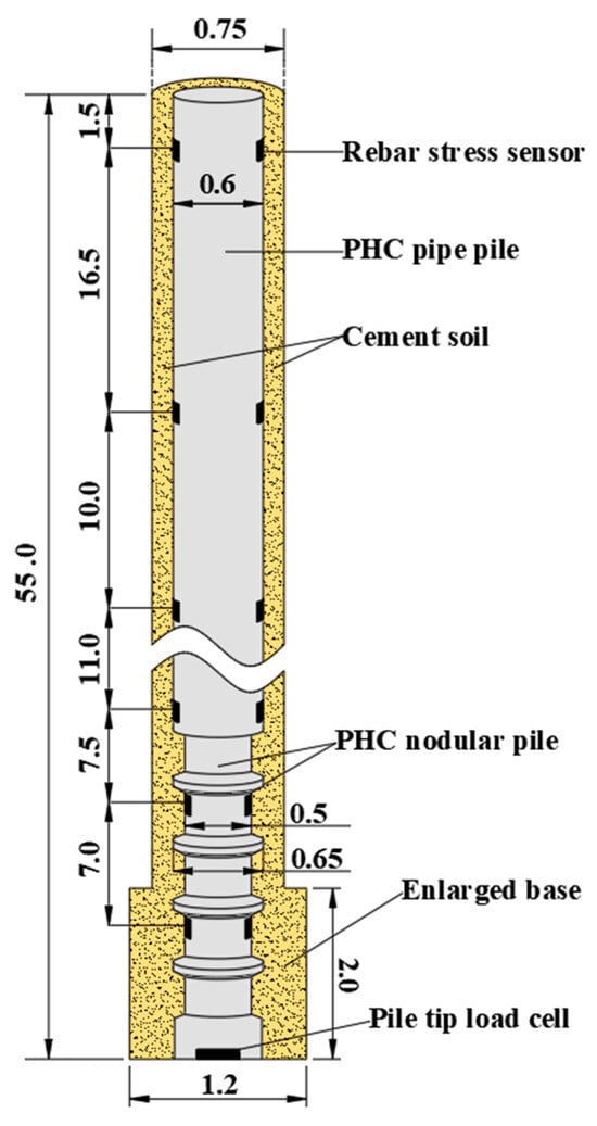
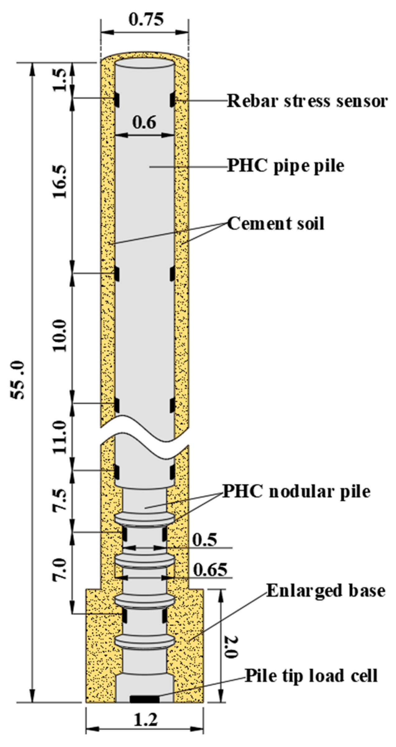
Two test piles were conducted in this study, and their structural schematic is shown in Figure 1. The total pile length L was 55 m, and the borehole diameter, namely the diameter of the cement soil column, was 750 mm. The core pile consisted of three pipe pile sections, each 15 m in length and 600 mm in diameter, and one nodular pile section with a length of 10 m. The nodular pile section was installed at the bottom. The shaft diameter of the nodular pile was 500 mm, while the diameter at the nodular parts was 650 mm. The pile tip was enlarged, with an enlarged base diameter of 1200 mm and an enlarged base height of 2000 mm.
Figure 1.
Schematic of the test pile (unit: m).
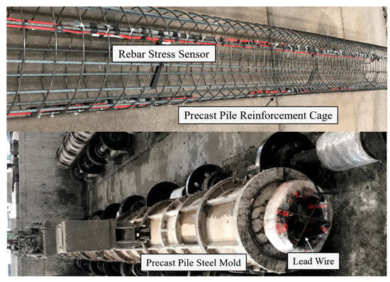
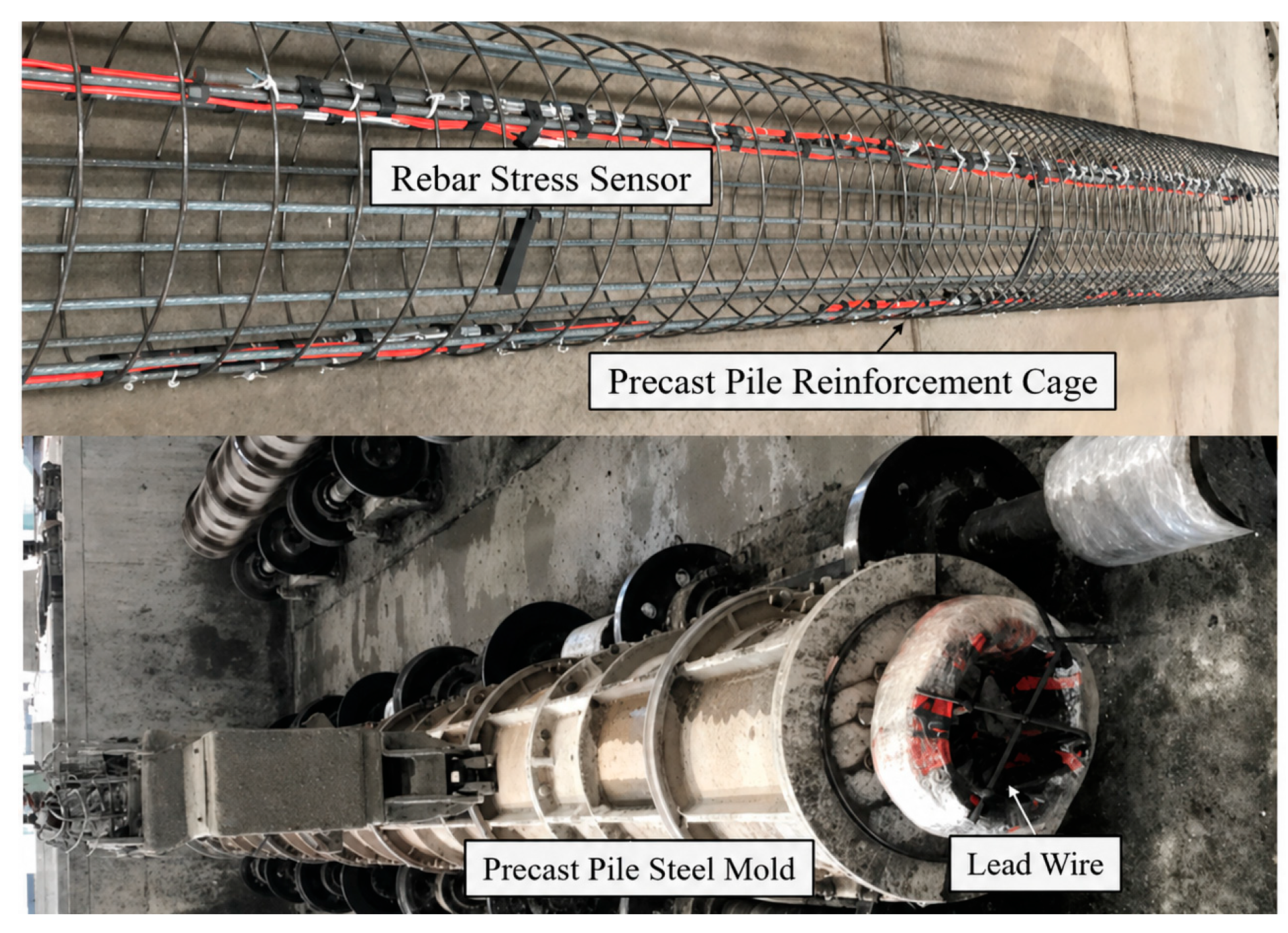
During the fabrication of the precast piles, rebar stress sensors were embedded in the reinforcement cage, as shown in Figure 2. According to the distribution of soil layers around the test piles, the rebar stress sensors were installed at depths of 1.5 m, 18 m, 28 m, 39 m, 46.5 m, and 53.5 m below the ground surface, as illustrated in Figure 1. Two rebar stress gauges were installed at each section. Based on the deformation compatibility between the reinforcement and concrete, the axial force of the pile shaft at the corresponding position can be calculated. In addition, a pile tip load cell was installed at the base of the precast pile to measure the pile tip resistance at each loading stage.
Figure 2.
Precast pile fabrication and rebar stress sensor installation.
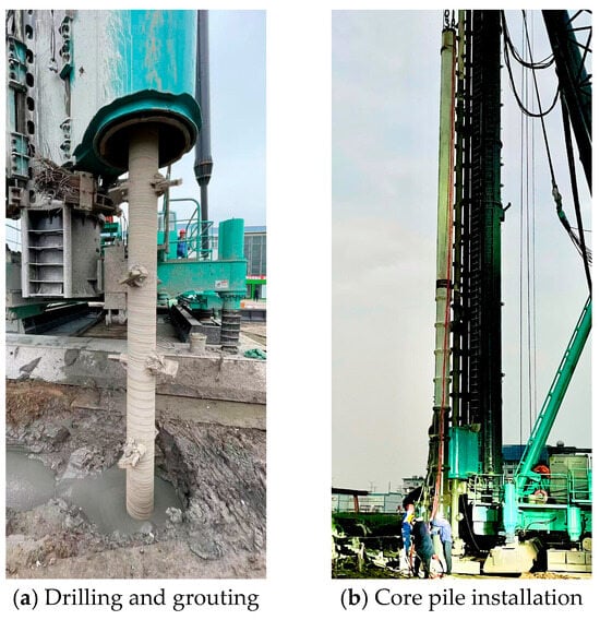
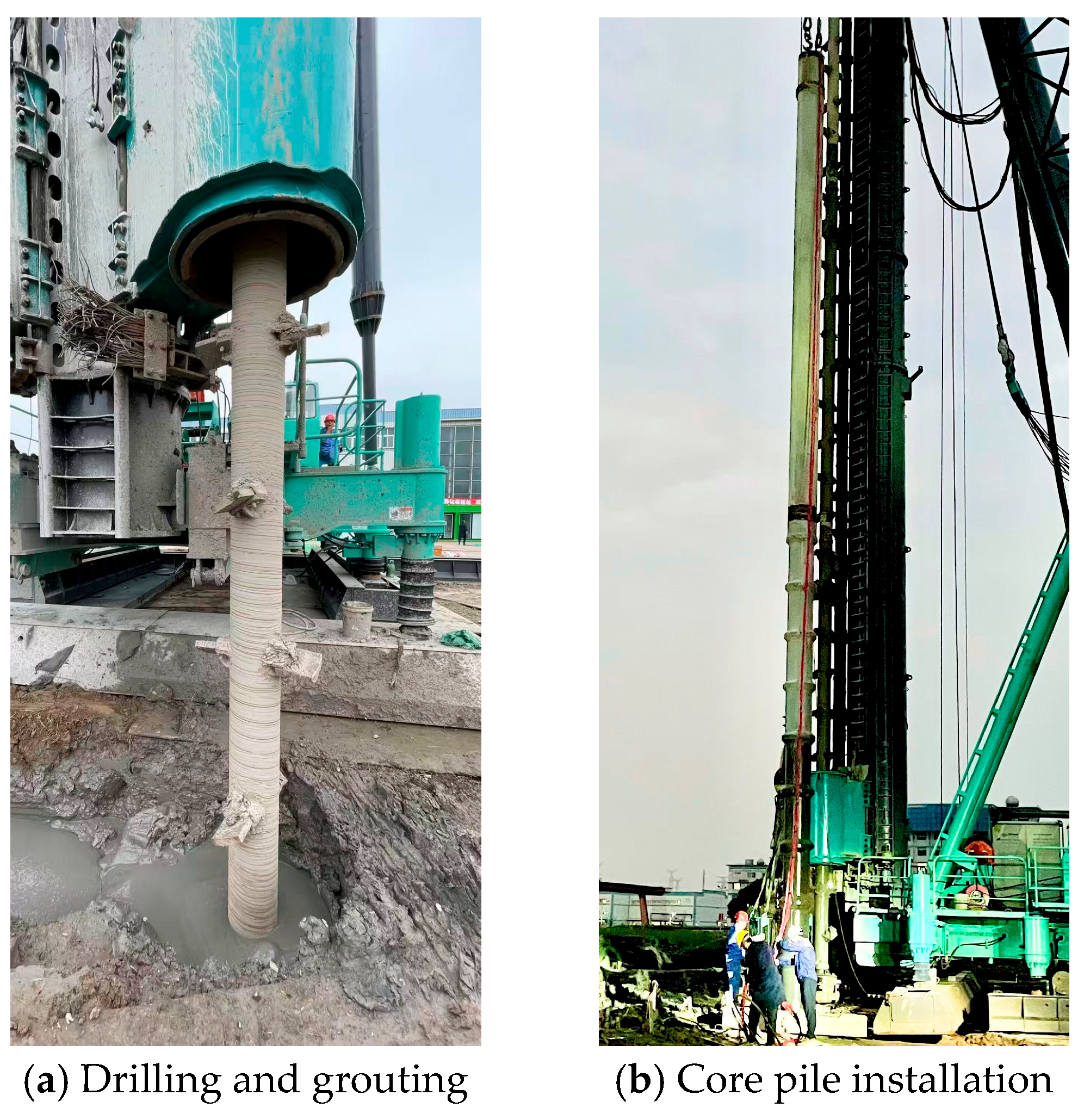
After the fabrication of the precast piles was completed, the PGP piles were constructed at the test site. The construction process consisted of several steps, including drilling, base enlargement, grouting, and pile installation, further details are provided in Reference [1]. Ordinary Portland cement (P.O 42.5) was used for preparing the cement slurry. The water–cement ratio of the cement slurry injected at the pile tip was 0.6, while that of the cement slurry around the pile shaft was 1.0. The grouting pressure was controlled within 0.2–0.3 MPa during shaft grouting and 0.5–0.6 Mpa during base grouting. The enlarged base was formed by opening the expandable wings of the drilling bit at the designed depth to enlarge the borehole bottom. During this process, the borehole bottom was enlarged to a diameter of 1200 mm over a height of 2000 mm before the precast core pile was installed. The grouting volume for a single pile was 6.5 m3, and the cement consumption was 3811 kg. Photographs of the field construction process of PGP piles are shown in Figure 3. After 28 days after construction, the cement soil had developed sufficient strength and static load tests were conducted. The vertical load was applied by hydraulic jacks using a combined kentledge–reaction frame loading system. The pile-head load and corresponding settlement were monitored synchronously using displacement sensors and an automatic static load testing system. The loading procedure and termination criteria were conducted in accordance with the specification [15]. The vertical load was applied by hydraulic jacks through a combined kentledge–reaction frame loading system. The pile-head load and corresponding settlement were synchronously monitored using displacement transducers and an automatic static load testing system. The slow maintained load method was adopted, and the load increment at each stage was taken as 10% of the maximum test load or the estimated ultimate bearing capacity.
Figure 3.
Construction process of PGP piles.
2.2. Test Results
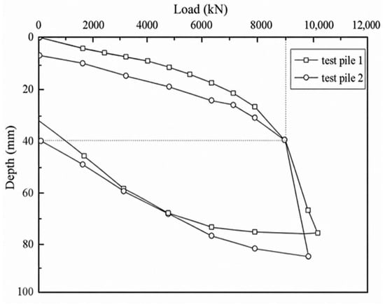
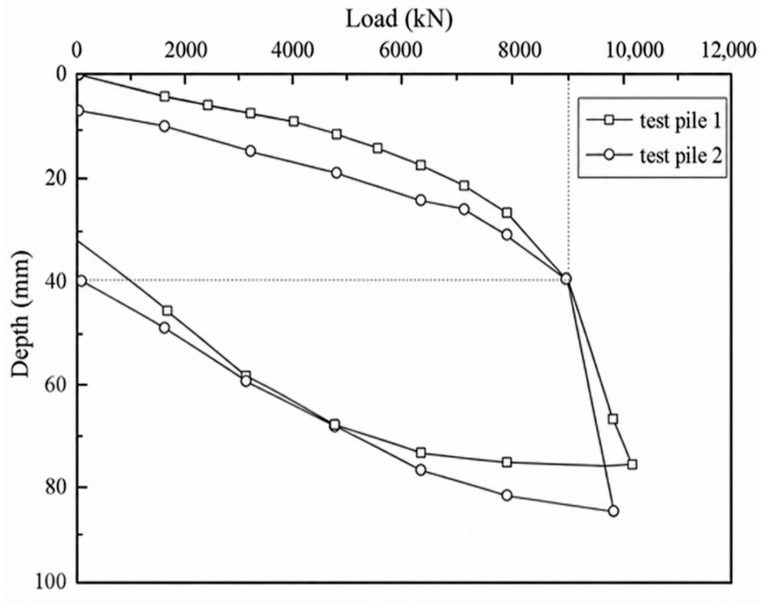
The two test piles under the same conditions were tested for comparison, so as to improve the reliability and repeatability of the observed trends. The load–displacement curves obtained from the static load tests are shown in Figure 4. According to the specification [15], for a steeply dropping load–displacement curve, the load corresponding to the onset of the obvious sharp drop is taken as the ultimate vertical compressive bearing capacity of a single pile. Therefore the ultimate compressive bearing capacities of test pile 1 and test pile 2 were both determined to be 8800 kN, the corresponding settlements were 39.7 mm and 39.9 mm, respectively. The points indicated by the dashed lines represent the ultimate states of the two test piles. Since the two piles had identical structural configurations and were installed at the same site, the overall load-bearing behavior was relatively consistent, although some differences were still observed in the test results.
Figure 4.
Load–displacement curves of the test piles.
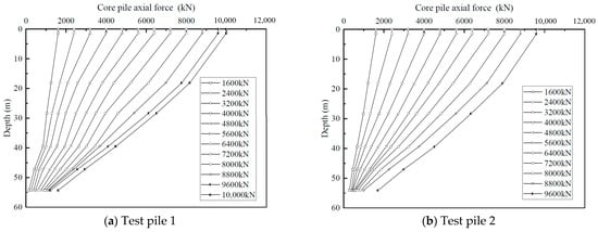
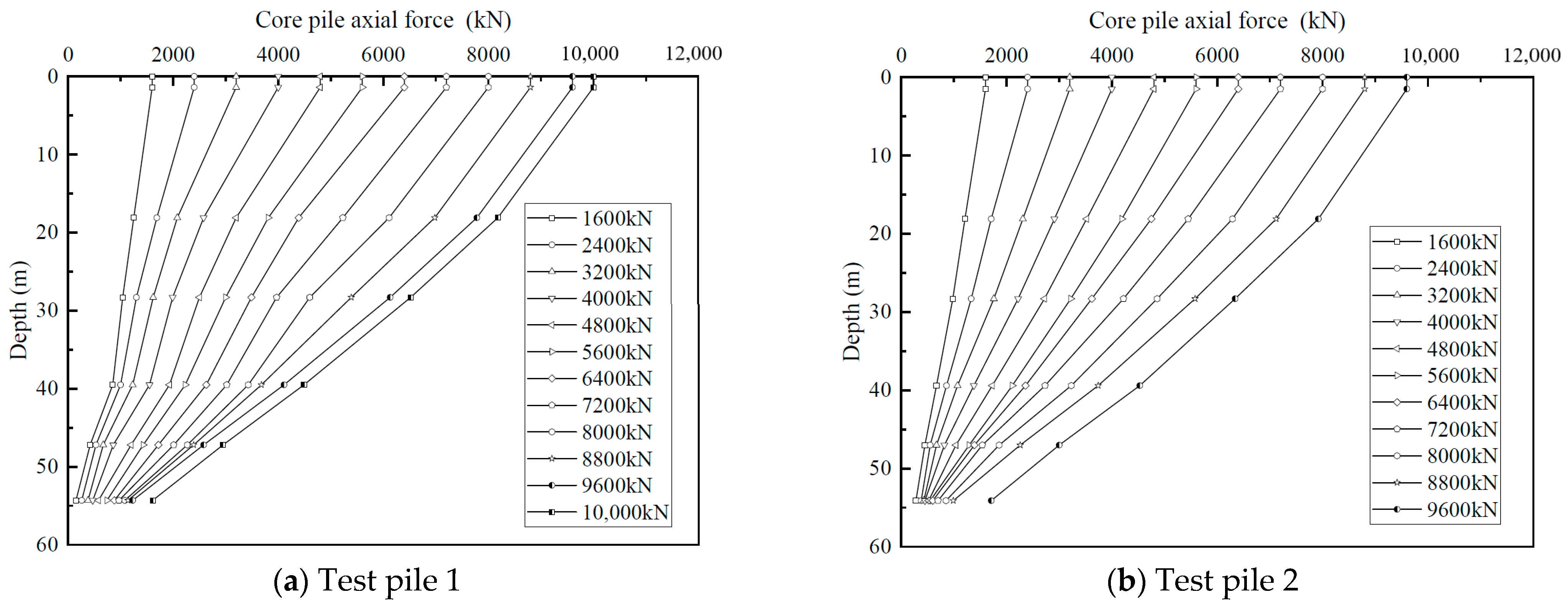
The axial force distribution along the core pile at different loading stages was measured using the embedded rebar stress sensors. At each instrumented section, two rebar stress sensors were installed, and their average value was used in the calculation. Based on strain compatibility between the embedded rebar and the surrounding concrete, the measured rebar stress was converted into the axial strain of the core pile. The axial force of the core pile was then obtained using the equivalent axial stiffness of the corresponding pile section. The elastic modulus of the rebar, the elastic modulus of the precast concrete core pile, and the cross-sectional areas of the pipe pile and nodular pile sections were used in the conversion. The results are presented in Figure 5. Based on these measurements, the variation in axial force with depth can be identified, which is essential for further evaluating the load transfer mechanism of the PGP piles.
Figure 5.
Core pile axial force.
3. Bearing Performance Analysis
3.1. Pile Shaft Bearing Performance
Based on the measured axial force of the core pile, the axial force in the cement–soil column and the shaft resistance at the cement soil-soil interface can be further derived and analyzed. Provided the core pile–cement soil interface does not fail during the test, and based on the composite linear constitutive model for the inner interface established in previous studies [16], the expression for the axial force in the cement soil column can be derived by combining the equilibrium of a core pile element with the relationship between displacement and strain, as follows:
where is the expression of core pile axial force along depth , obtained by fitting the measured axial force data points in Figure 5 using a cubic spline function; where is the expression of cement soil axial force along depth; and are the cross-sectional areas of the core pile and cement soil, respectively; and are the elastic moduli of the core pile and cement soil, respectively; is the diameter of the core pile; and is the stiffness of the core pile–cement soil interface, the interface stiffnesses of the pipe pile and nodular pile segment were obtained from laboratory model tests [16] and relative reference [17].
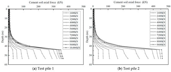
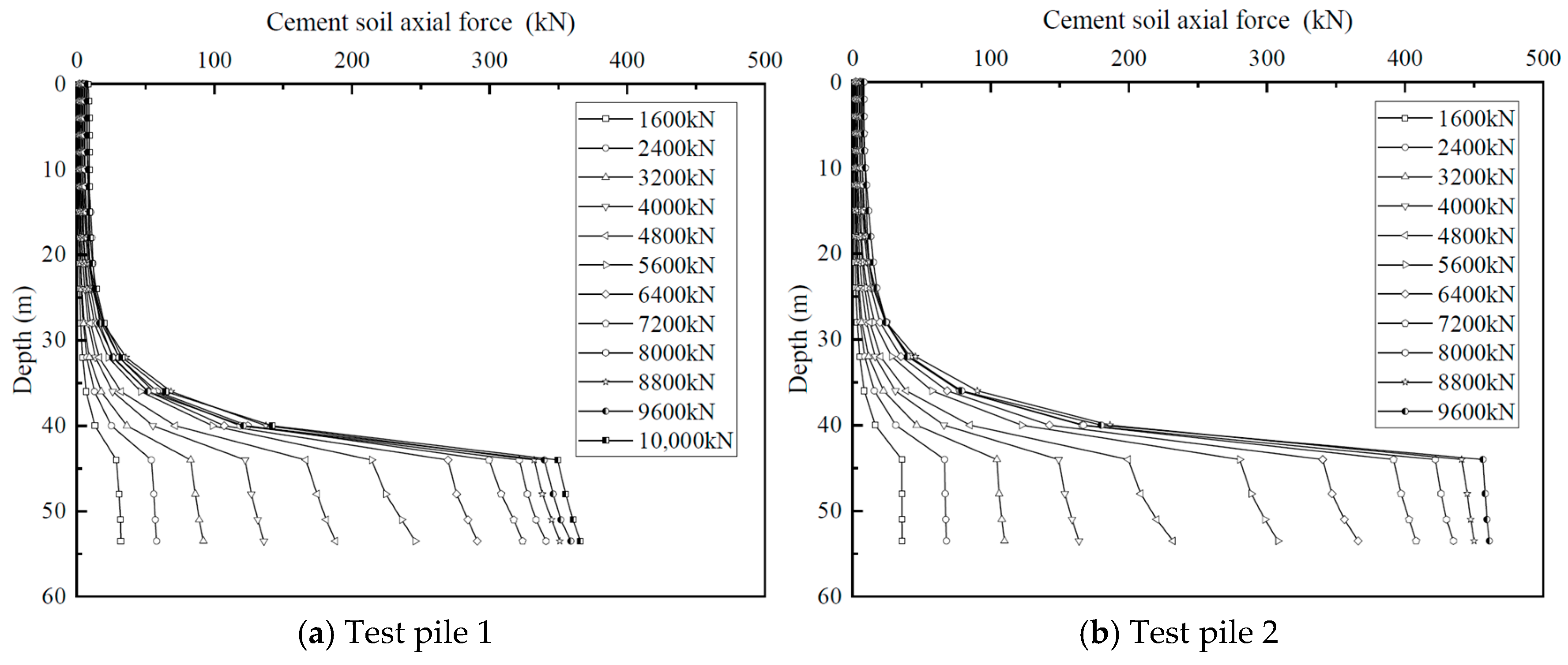
The axial force of the cement soil can be calculated using Equation (1), and the distribution of the axial force in cement soil is shown in Figure 6.
Figure 6.
Cement soil axial force.
As shown in Figure 6, the axial force of the cement soil is relatively small in the upper part of the pile shaft and increases rapidly in the lower part. A marked change in the axial force occurs at the transition connection between the pipe pile and the nodular pile. Thereafter, the axial force increases slowly along the nodular core pile section. Considering the structural feature (Figure 1), the most unfavorable position of the cement soil is located at the end of the enlarged base, namely at a depth of z = 53 m, where the cross-sectional area of the cement soil suddenly decreases upward from the enlarged base section. Therefore, the strength of cement soil at this position should be checked. At z = 53 m, the maximum axial force of cement soil is 457.34 kN, corresponding to a vertical stress of 2856.25 kPa. Cement soil specimens with the same mix proportion as that used in the test piles were prepared in the laboratory and tested at a curing age of 28 days. The average compressive strength measured from five specimens was 3125.78 kPa, which is greater than the actual vertical stress. This indicates that the cement soil satisfies the strength requirement, and no failure occurs in the cement soil throughout the test pile.
Furthermore, based on the equilibrium of the total axial force of the composite pile, the expression for the unit shaft resistance at the cement soil–soil interface can be derived as follows:
where is the shear stress of cement soil–soil interface along depth.
The specification states that the pile–soil relative displacement can be approximately represented by the pile shaft displacement [15]. Therefore, the pile–soil relative displacement is equal to the displacement of the cement soil, which can be expressed as follows:
where is the displacement of the cement soil at depth , and is the pile-head displacement.
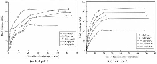
The variation in the shaft resistance with the pile–soil relative displacement can be obtained from Equations (2) and (3), as shown in Figure 7.
Figure 7.
Curves of shaft resistance varying with pile–soil relative displacement.
When calculating the axial force of the cement soil and the shaft resistance at the outer interface using the above equations, it was assumed that no failure occurred at the inner interface. Therefore, the strength of the inner interface should be verified.
In this field test, the strength of the cement-treated soil around the pile reached 1.5 MPa. According to the results of the precast pile–cement soil interface shear tests conducted by our research team [16], the ultimate shaft resistance of the precast pile–cement soil interface was 160 kPa. As shown in Figure 1, the borehole diameter and the core pile diameter of the test pile were 750 mm and 600 mm, respectively, with a diameter ratio of 1.25. Therefore, when the ultimate shaft resistance at the cement soil–soil interface is less than 128 kPa, failure will not occur at the core pile–cement soil interface during load transfer.
According to the results shown in Figure 7, the shaft resistance at the outer interface was less than 128 kPa in all cases. Therefore, the inner interface did not fail during the test, and the calculation procedure based on this assumption is valid.
The ultimate shaft resistance of the two test piles and those of bored piles specified in the code are summarized in Table 2. In this study, the ultimate shaft resistance of the PGP piles in different soil layers was 1.49–3.21 times that of the ultimate shaft resistance of bored piles recommended by the design code. It can be understood from the structural characteristics and construction process of PGP piles that the grouting stage during construction allows the cement slurry to penetrate and diffuse into the surrounding soil, thereby strengthening and solidifying the surrounding soil. As a result, the frictional performance at the pile–soil interface is significantly improved, and the enhancement of shaft resistance becomes more pronounced in soils with poorer properties.
Table 2.
Ultimate shaft resistance in each soil layer.
3.2. Pile Tip Bearing Performence
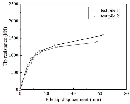
The compressive stress at the pile tip of the test pile under each loading stage can be measured by the pile-tip load cell. Multiplying the measured stress by the cross-sectional area of the core pile yields the tip resistance. The pile-tip displacement can be calculated using Equation (4), which is equal to the pile-head settlement minus the compression deformation of the pile shaft.
Accordingly, the relationship curves between the pile-tip resistance and pile-tip displacement can be obtained, as shown in Figure 8. When the test piles were loaded to the ultimate compressive bearing capacity (8800 kN load level), the pile-tip resistance of test pile 1 and test pile 2 were 1136.12 kN and 1293.63 kN, respectively.
Figure 8.
Tip resistance of the test piles.
Under the assumption that the soil beneath the pile tip can be simplified as an elastic foundation, a linear proportional relationship between the pile-tip resistance and the pile-tip displacement can be assumed. After derivation, the total pile-tip resistance of the PGP pile can be expressed by Equation (5).
where is the total pile-tip resistance; and are the end resistances of the core pile and cement soil, respectively; and are the subgrade stiffnesses per unit area corresponding to the core pile and cement soil, respectively; is the shear stress at the core pile–cement soil interface at the pile tip; and represents the relative displacement of the interface at the pile tip.
It can be seen from Equation (5) that the smaller the relative displacement at the interface, the greater the end resistance that can be carried by the cement soil, and consequently the greater the total pile-tip resistance. Therefore, adopting a nodular pile design for the lowermost section of the core pile in a PGP pile can significantly enhance the interface stiffness and reduce the relative displacement at the core pile–cement soil interface near the pile tip. This enables the cement soil to bear a larger proportion of the end resistance, thereby effectively improving the pile-tip bearing capacity.
Because a nodular core pile structure was adopted at the pile tip, the relative displacement at the interface between core pile and cement soil was very small. Therefore, for simplicity, the total pile-tip resistance can also be expressed by Equation (6) when the relative displacement at the internal interface is neglected.
where can be regarded as the effective bearing area at the pile tip of the PGP pile, and is defined as the effective pile-tip area of the PGP pile.
Compared with conventional pile types, the existence of the cement soil layer increases the effective compressive area at the pile tip, resulting in superior pile-tip bearing performance of the PGP pile. During construction, the enlarged base can further increase the bottom area of the cement soil, thereby improving the pile-tip resistance of the PGP pile. The ratio reflects the degree to which the bottom area of the cement soil is transformed into the effective bearing area. According to Figure 6 on cement soil axial force, under the ultimate compressive bearing capacity condition, the end resistance carried by the cement soil in test pile 1 and 2 were 346.21 kN and 452.16 kN, respectively. Under the assumption that the relative displacement at the interface is approximately zero, the calculated value of is approximately 0.12 under the ultimate compressive bearing capacity condition, while it is approximately 1 at the initial loading stage. This indicates that, with the gradual increase in load, the effective area of the bottom surface of the cement soil decreases continuously. It can be calculated that when the pile is loaded to the ultimate compressive bearing capacity, the end resistance carried by the cement soil accounts for approximately 26% of the total pile-tip resistance.
4. Calculation Method for Bearing Capacity and Settlement
4.1. Calculation Method for Shaft Resistance
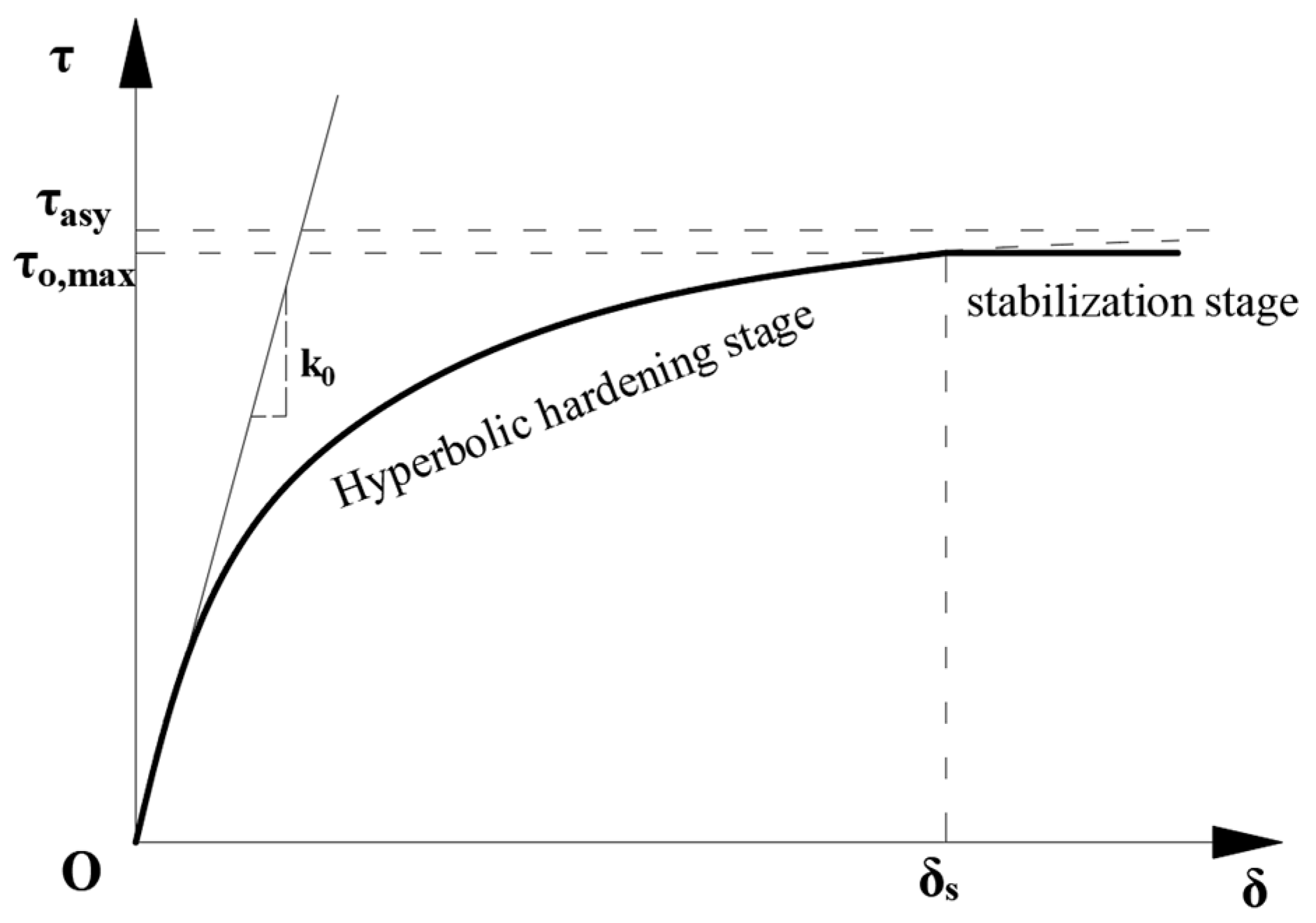
Kondner et al. [18] and Duncan et al. [19] adopted nonlinear hyperbolic models to describe the shear stress–strain relationships of clay and sand, respectively, which exhibit the same form and trend as the shaft resistance–relative displacement curves obtained in this study. Based on their approaches, a constitutive model for the shaft resistance of PGP piles is established in this paper, as shown in Figure 9.
Figure 9.
Constitutive model for shaft resistance of PGP pile.
The relationship between the shaft resistance and the pile–soil relative displacement in the hyperbolic segment can be expressed by Equation (7).
where is the shaft resistance; is the pile–soil relative displacement; is the ordinate value of the asymptote of the hyperbola; is the initial shear stiffness of the interface, which is equal to the tangent slope of the hyperbola at the origin, and can be expressed as follows:
where is the ultimate shaft resistance; is the pile–soil relative displacement corresponding to the full mobilization of shaft resistance in a given soil layer, and its value can be determined based on the field test results.
Referring to Duncan et al. [19], the ratio of to is defined as the failure ratio . The value of generally ranges from 0.85 to 0.95.
For the calculation of the ultimate shaft resistance , the pile shaft resistance calculation method recommended by the American Petroleum Institute (API) [20] was adopted and modified to account for the grouting enhancement effect of PGP piles.
For soft clay, silty clay, clayey silt and similar soils, due to their low permeability, undrained or partially drained conditions are often encountered during conventional construction. Therefore, the method (total stress method) is commonly adopted for calculation. To account for the grouting-induced enhancement effect of PGP piles, a grouting enhancement coefficient is introduced and defined as follows:
where is the undrained shear strength of the soil; is the undrained shear strength of the soil after the grouting enhancement effect.
Accordingly, the ultimate shaft resistance of PGP pile in soft soil can be calculated by the following equation:
For PGP piles, the calculation formula for is given as follows:
where is the vertical effective stress at the calculated position.
By substituting the ultimate shaft resistances of the pre-bored grouted planted piles obtained from the field tests in each soil layer into Equation (10), the grouting enhancement coefficient can be back-calculated. The calculated values of for soft clay, silty clay 1, silty clay 2, clayey silt 1 and clayey silt 2 in this test field are 3.03, 2.68, 2.36, 2.18 and 2.03, respectively. It can be seen that soils with poorer properties and lower strength have larger grouting enhancement coefficients.
The values of obtained in this study can provide a reference for practical engineering applications. Accordingly, the ultimate shaft resistance of PGP piles in different soil layers can be calculated when the soil parameters are known. However, the values of for different soil layers still require further verification and improvement through additional tests and engineering applications. This study focuses on proposing a method for accurately calculating the shaft resistance of pre-bored grouted planted piles. Due to the limitations of the present study, the further refinement of values and the validation of the proposed method still require additional experimental investigations in future research.
4.2. Calculation Method for Tip Resistance
For the pile-tip load transfer model, Briaud and Tucker [21], Hirayama [22], and Fleming [23] adopted hyperbolic functions to describe the development of pile-tip resistance with displacement. The pile-tip resistance–pile-tip displacement curves obtained from the field tests of PGP piles (Figure 8) are generally consistent with the evolution trend of the hyperbolic model. Therefore, a hyperbolic model (same to Figure 9) is also adopted in this study to describe the relationship between pile-tip resistance and pile-tip displacement of PGP pile.
The nonlinear relationship between the pile-tip resistance and the pile-tip displacement can be expressed as follows:
where is the pile-tip displacement; is initial stiffness of the pile-tip foundation, Randolph and Wroth [24] derived based on the solution for a rigid body penetrating an elastic half-space, which can be calculated as follows:
where is the shear modulus of the bearing stratum soil at the pile tip; is the Poisson’s ratio of the bearing stratum soil at the pile tip; and is the pile-tip radius, which is equal to the radius of the precast pile in a PGP pile.
is the ultimate pile-tip resistance, which can be calculated using the pile-tip bearing capacity Equation (14) proposed by Meyerhof [25].
where is the effective cohesion of the soil at the pile tip; and are the bearing capacity factors of the pile-tip soil, which can be determined according to the summary and recommendations of Meyerhof [25]; and is the effective pile-tip area of the pre-bored grouted planted pile, which has been defined in Equation (6).
4.3. Calculation Method the Ultimate Bearing Capacity and Settlement
Based on the field test results, a simplified calculation method for the ultimate compressive bearing capacity and settlement of PGP piles suitable for engineering applications is proposed in this study. According to the field test results, when the pre-bored grouted planted pile reaches the ultimate bearing state, more than 80% of both the shaft resistance and pile-tip resistance are mobilized. Therefore, 0.8 times the ultimate shaft resistance and pile-tip resistance can be adopted as the corresponding values when the pile reaches the ultimate bearing capacity. Therefore, the characteristic value of the ultimate compressive bearing capacity of the PGP pile can be estimated by Equation (15).
where the soil foundation is divided into layers according to the soil stratification, with = 1, 2, …, ; is the ultimate shaft resistance of the PGP pile in the -th soil layer, which can be calculated by Equation (10); is the thickness of the -th soil layer; and can be calculated by Equation (14).
The settlement can be estimated using the layer-wise summation method recommended in the design codes [12,15]. In this section, another estimation method is proposed. Since the ultimate pile-tip resistance has already been calculated during the estimation of the ultimate bearing capacity, the pile-tip displacement can be obtained according to Equation (12). By further adding the compression deformation of the pile shaft , the pile-head settlement can be obtained. Because the elastic modulus of the core pile is much greater than that of the cement soil, the compression deformation of the pile shaft can be approximately taken as the compression deformation of the core pile. Therefore, the settlement of the PGP pile can be estimated by Equation (16).
where is the depth of the bottom surface of the -th soil layer, and is the depth of the top surface of the -th soil layer.
For cases where a soft underlying layer exists beneath the pile tip, the compression deformation of the soft underlying layer should also be included in the settlement calculation.
4.4. Verification of the Calculation Method
To verify the applicability of the proposed simplified calculation method, the ultimate compressive bearing capacity and the corresponding settlement of the two test piles were calculated using Equations (15) and (16), respectively. Since the proposed method is intended for the ultimate bearing state, only the ultimate bearing capacity and the settlement corresponding to the ultimate load were compared with the measured results.
First, the ultimate shaft resistance of each soil layer was calculated using Equation (10). In this calculation, the grouting enhancement coefficients for soft clay, silty clay 1, silty clay 2, clayey silt 1, and clayey silt 2 were taken as 3.03, 2.68, 2.36, 2.18, and 2.03, respectively, as back-calculated from the field test results in this study. The remaining soil parameters and pile dimensions were adopted from the field test conditions reported above. The calculated ultimate shaft resistance values and their corresponding contributions to the ultimate bearing capacity are summarized in Table 3.
Table 3.
Calculation of ultimate shaft resistance for each soil layer.
According to Table 3, the total ultimate shaft resistance of the PGP pile was calculated to be 8341.2 kN. In Equation (15), 80% of the ultimate shaft resistance was adopted when estimating the ultimate compressive bearing capacity; therefore, the shaft resistance contribution used in the calculation was 6672.9 kN.
Second, the ultimate pile-tip resistance was calculated using Equation (14). The effective pile-tip area defined above and the strength parameters of the bearing stratum were used in the calculation [25]. The calculated ultimate pile-tip resistance was 1680.1 kN. Accordingly, the pile-tip resistance contribution adopted in Equation (15) was 0.8 = 1344.1 kN.
By substituting the shaft resistance contribution and pile-tip resistance contribution into Equation (15), the calculated ultimate compressive bearing capacity was obtained as 8017.1 kN. Since the two test piles had the same structural configuration and were constructed at the same test site, the same calculated ultimate bearing capacity was obtained for both piles.
Furthermore, the settlement corresponding to the ultimate load was calculated using Equation (16). The calculated settlement was 42.82 mm. The comparison between the calculated and measured results is presented in Table 4.
Table 4.
Comparison between measured and calculated ultimate bearing capacity and corresponding settlement.
As shown in Table 4, the calculated ultimate bearing capacity was 8.9% lower than the measured value. The calculated settlement corresponding to the ultimate load was 7.6% larger than the average measured settlement of the two test piles. Therefore, the proposed simplified calculation method slightly underestimated the ultimate compressive bearing capacity and slightly overestimated the corresponding settlement.
This indicates that the proposed calculation method provides a conservative estimation for the two field test piles. Such a conservative tendency is acceptable and beneficial for engineering design, because it leads to a lower predicted bearing capacity and a larger predicted settlement. However, it should be noted that the values used in this verification were back-calculated from the present field tests. Therefore, they should be regarded as site-specific calibrated parameters rather than general recommended values. Further field tests under different geological conditions are still required to validate and refine the grouting enhancement coefficients and to improve the general applicability of the proposed calculation method.
5. Conclusions
Based on field static load tests and measured axial force data, this study investigated the compressive bearing performance and load transfer mechanism of pre-bored grouted planted piles. Calculation methods for shaft resistance, tip resistance, ultimate bearing capacity, and settlement were further proposed. The main conclusions are as follows:
- (1)
- The two test piles exhibited high vertical compressive bearing capacity, with an ultimate bearing capacity of 8800 kN. The measured axial force showed that the load was mainly transferred downward through the core pile and gradually mobilized the surrounding cement soil. The most unfavorable position of the cement soil is located at the end of the enlarged base, therefore the strength of cement soil at this position should be checked.
- (2)
- The shaft resistance at the cement soil–soil interface was significantly enhanced by the grouting process. The ultimate shaft resistance of the PGP piles was approximately 1.49–3.21 times that of bored cast-in-place piles recommended by the design code. This improvement was mainly attributed to slurry penetration, diffusion, and solidification around the pile shaft, and was more evident in weaker soils.
- (3)
- The enlarged base and nodular core pile section improved the pile-tip bearing performance. The nodular pile section increased the interface stiffness near the pile tip and promoted the participation of cement soil in end bearing. Under the ultimate load, the end resistance carried by the cement soil accounted for about 26% of the total pile-tip resistance.
- (4)
- Hyperbolic models were adopted to describe the shaft resistance–relative displacement and pile-tip resistance–settlement relationships. Based on these models, simplified calculation methods for ultimate bearing capacity and settlement were proposed by considering the enhanced shaft resistance and effective pile-tip area. The proposed method provides a practical reference for the design and application of PGP piles, although the grouting enhancement coefficients still require further validation through additional field tests.
Based on the field test results, calculation methods for the bearing capacity and settlement of pre-bored grouted planted piles are proposed in this study. Nevertheless, owing to the limitations of the experimental conditions, further field tests are still needed to validate and improve the proposed methods.
Author Contributions
Resources, X.G.; data curation, J.M.; writing—original draft preparation, J.M.; writing—review and editing, J.M.; project administration, X.G. All authors have read and agreed to the published version of the manuscript.
Funding
This research received no external funding.
Data Availability Statement
Some or all data, models, or code produced or utilized in this study can be obtained upon request from the corresponding author.
Conflicts of Interest
The authors declare no conflicts of interest.
References
- Ma, J.; Gong, X.; Hu, X.; Lei, G.; Zhang, R. Field Test on the Application of Industrial Solid Waste in the Grouting Process of Pre-Bored Grouted Planted Pile. Buildings 2025, 15, 29. [Google Scholar]
- Zhou, J.; Yu, J.; Gong, X.; Zhang, R. Field Study on Installation Effects of Pre-Bored Grouted Planted Pile in Deep Clayey Soil. Can. Geotech. J. 2024, 61, 748–762. [Google Scholar] [CrossRef] [Scilit]
- Zhou, J.J.; Gong, X.N.; Zhang, R.H.; El Naggar, M.H.; Wang, K.H. Field Behavior of Pre-Bored Grouted Planted Nodular Pile Embedded in Deep Clayey Soil. Acta Geotech. 2020, 15, 1847–1857. [Google Scholar]
- Wang, C.; Xu, Y.; Dong, P. Plate Load Tests of Composite Foundation Reinforced by Concrete-Cored DCM Pile. Geotech. Geol. Eng. 2014, 32, 85–96. [Google Scholar]
- He, B.; Wang, L.Z.; Hong, Y. Capacity and Failure Mechanism of Laterally Loaded Jet-Grouting Reinforced Piles: Field and Numerical Investigation. Sci. China Technol. Sci. 2016, 59, 763–776. [Google Scholar] [CrossRef] [Scilit]
- Wonglert, A.; Jongpradist, P.; Jamsawang, P.; Larsson, S. Bearing Capacity and Failure Behaviors of Floating Stiffened Deep Cement Mixing Columns under Axial Load. Soils Found. 2018, 58, 446–461. [Google Scholar] [CrossRef] [Scilit]
- Jamsawang, P.; Bergado, D.T.; Voottipruex, P. Field Behaviour of Stiffened Deep Cement Mixing Piles. Proc. Inst. Civ. Eng. Ground Improv. 2011, 164, 33–49. [Google Scholar] [CrossRef] [Scilit]
- Voottipruex, P.; Suksawat, T.; Bergado, D.T.; Jamsawang, P. Numerical Simulations and Parametric Study of SDCM and DCM Piles under Full Scale Axial and Lateral Loads. Comput. Geotech. 2011, 38, 318–329. [Google Scholar] [CrossRef] [Scilit]
- Zhu, S.; Chen, C.; Cai, H.; Mao, F. Analytical Modeling for the Load-Transfer Behavior of Stiffened Deep Cement Mixing (SDCM) Pile with Rigid Cap in Layer Soils. Comput. Geotech. 2022, 144, 104618. [Google Scholar] [CrossRef] [Scilit]
- Tiutkin, O.; Radkevych, A.; Dubinchyk, O.; Kharchenko, V. Parametric Analysis of a Strain State of a Soil Base Strengthened with Vertical Elements. Min. Miner. Depos. 2024, 18, 104–112. [Google Scholar] [CrossRef] [Scilit]
- Lukpanov, R.E.; Yenkebayev, S.B.; Tsigulyov, D.V. Assessment of the Bearing Capacity of Piles in Soil, Determined by Static and Dynamic Load Tests. Eng. J. Satbayev Univ. 2021, 143, 252–260. [Google Scholar] [CrossRef] [Scilit]
- JGJ 94-2008; Technical Code for Building Pile Foundations. China Architecture & Building Press: Beijing, China, 2008.
- T/CECS 738-2020; Technical Specification for Pre-Bored Grouted Planted Piles. China Planning Press: Beijing, China, 2020.
- He, S.-H.; Yin, Z.-Y.; Ding, Z.; Li, R.-D.; Liao, D. Drained Deformation and Non-Coaxiality of Granular Materials under Pure Principal Stress Rotation: Role of Particle Morphology. Acta Geotech. 2026. [Google Scholar] [CrossRef] [Scilit]
- JGJ 106-2014; Technical Code for Testing of Building Foundation Piles. China Architecture & Building Press: Beijing, China, 2014.
- Zhou, J.; Ren, J.; Ma, J.; Yu, J.; Zhang, R.; Gong, X. Laboratory Tests on the Frictional Capacity of Core Pile–Cemented Soil Interface. Proc. Inst. Civ. Eng. Geotech. Eng. 2024, 177, 692–701. [Google Scholar] [CrossRef] [Scilit]
- Yan, Y.; Xie, B.; Zhao, P.; Liu, Y.; Xu, B. DEM Study of the Shear Behavior at the Nodular Pile–Cemented Soil Interface in Static Drill-Rooted Nodular Pile. Adv. Powder Technol. 2026, 37, 105157. [Google Scholar]
- Kondner, R.L. Hyperbolic Stress-Strain Response: Cohesive Soils. J. Soil Mech. Found. Div. 1963, 89, 115–143. [Google Scholar] [CrossRef] [Scilit]
- Duncan, J.M.; Chang, C.Y. Nonlinear Analysis of Stress and Strain in Soils. J. Soil Mech. Found. Div. 1970, 96, 1629–1653. [Google Scholar] [CrossRef] [Scilit]
- API RP 2GEO/ISO 19901-4:2003; Geotechnical and Foundation Design Considerations. 1st ed. American Petroleum Institute: Washington, DC, USA, 2011.
- Briaud, J.L.; Tucker, L.M. Piles in Sand: A Method Including Residual Stresses. J. Geotech. Eng. 1984, 110, 1666–1680. [Google Scholar] [CrossRef] [Scilit]
- Hirayama, H. Load-Settlement Analysis for Bored Piles Using Hyperbolic Transfer Functions. Soils Found. 1990, 30, 55–64. [Google Scholar] [CrossRef] [Scilit]
- Fleming, W.G.K. A New Method for Single Pile Settlement Prediction and Analysis. Géotechnique 1992, 42, 411–425. [Google Scholar]
- Randolph, M.F.; Wroth, C.P. Analysis of Deformation of Vertically Loaded Piles. J. Geotech. Eng. Div. 1978, 104, 1465–1488. [Google Scholar] [CrossRef] [Scilit]
- Meyerhof, G.G. Bearing Capacity and Settlement of Pile Foundations. J. Geotech. Eng. Div. 1976, 102, 197–228. [Google Scholar] [CrossRef] [Scilit]

Disclaimer/Publisher’s Note: The statements, opinions and data contained in all publications are solely those of the individual author(s) and contributor(s) and not of MDPI and/or the editor(s). MDPI and/or the editor(s) disclaim responsibility for any injury to people or property resulting from any ideas, methods, instructions or products referred to in the content. |
© 2026 by the authors. Licensee MDPI, Basel, Switzerland. This article is an open access article distributed under the terms and conditions of the Creative Commons Attribution (CC BY) license.