


Abstract
Fabricated reinforced concrete columns are important components of reinforced concrete structures. During the design reference period, columns are prone to degradation in mechanical and deformation properties, which affects the normal service of the structure. Based on compressive tests of fabricated reinforced concrete columns, this paper uses ABAQUS 2021 finite element analysis software to explore how factors such as column damage and CFRP sheet layout affect the compressive performance of fabricated concrete columns under eccentric compression in order to investigate their mechanical properties and the confinement effect of CFRP sheets on such columns. The results indicate that the change trend of the bearing capacity of the finite element model is largely in agreement with that of the test specimens, and the ultimate bearing capacity error is below 3%, thereby confirming the validity of the finite element model. Compared with strip confinement, full-wrap confinement achieves a greater improvement in ultimate bearing capacity, and two to three layers are recommended as the ideal number of CFRP sheets for strengthening. The maximum increase in ultimate bearing capacity can reach 19.18%. When the strip width is constant, the smaller the spacing, the smaller the concrete strain in the compression zone. When the net spacing is constant, reducing the strip width increases the number of cracks and decreases crack width, but reduces the ultimate bearing capacity of the column accordingly. Strengthening with CFRP sheets can enhance the ultimate bearing capacity, deformability, and ductility of columns with initial damage under both small and large eccentric compression. The maximum increase in ultimate bearing capacity can reach 8.31%. The results obtained in this paper are conducive to promoting the reinforcement and reconstruction of fabricated reinforced concrete columns and reinforced concrete structures.
1. Introduction
Against the background of increasingly severe global climate change, unprecedented transformation pressure is bearing down on the construction industry, which is a major sector in energy consumption and carbon emissions [1,2,3,4]. Monolithic fabricated structures are composed of precast concrete components connected in reliable ways, and play a prominent role in improving people’s living environment and quality of life [5,6].
However, under the long-term combined effects of natural and service environments, many existing building structures (especially beam and column members) have insufficient safety and serviceability, failing to meet current usage requirements and urgently needing repair, strengthening, and reinforcement [7]. It is imperative to explore strengthening technologies for fabricated building structures. In practical engineering, limited by research funds and design difficulties, many aspects are difficult to study directly through experimental methods, while numerical simulation can make up for the shortcomings of experimental means and conduct comprehensive stress analysis of structures. Hence, investigating the mechanical properties of fabricated reinforced concrete columns through a combination of experimental research and finite element analysis methods holds significant theoretical importance and practical value for advancing the process of urban renewal.
Since the 20th century, research on the monolithic precast concrete structure with precast outer shell and cast-in-place core has been carried out successively within China and overseas. According to the research results and the performance of practical engineering cases, this structural form exhibits excellent overall stability and seismic performance [8,9,10,11]. The finite element model (FEM) offers several notable strengths. It can accurately represent complex geometries and boundary conditions, and it is capable of accounting for complex behaviors such as material nonlinearity, geometric nonlinearity, and contact interactions between multiple components. These characteristics render the finite element method an indispensable and powerful tool in both engineering analysis and scientific research. Methee et al. employed a self-developed program based on finite element software to simulate and analyze the seismic performance of fabricated concrete bridge columns. By comparing the calculated results with the experimental results, they found that the program could accurately simulate the seismic characteristics of the structure. Finally, an investigation into the seismic response of the structure induced by ground motion was conducted based on nonlinear dynamic time-history analysis [12]. Using finite element analysis, Xiao et al. assessed how internal grouting defects in grouting sleeves influence the structural performance of precast reinforced concrete columns. It was found that with the increase in the grouting defect ratio, the reinforced concrete columns showed obvious performance degradation such as stiffness degradation, increased plastic deformation, and weakened energy dissipation capacity [13]. Cao et al. conducted a numerical evaluation with respect to the seismic performance of precast recycled aggregate concrete structural columns utilizing ABAQUS, verifying the correlation between the ductility coefficient of precast columns and the projected length of longitudinal reinforcement bending [14]. John employed finite element modeling to numerically simulate the mechanical behavior of FRCM-strengthened reinforced concrete columns under seismic loading, building upon experimental investigations. The FEM was validated against experimental data, and the simulation results demonstrated good agreement with the tests. This numerical analysis further revealed the stress distribution and deformation characteristics within the strengthened columns, providing a basis for the optimization of FRCM strengthening schemes [15]. To summarize the above, through comparative verification of finite element simulation and experiments, these studies consistently reveal that the finite element analysis method can successfully simulate the mechanical properties and seismic response of fabricated concrete structures, providing full proof of its reliability and applicability in structural research.
As emerging materials in civil engineering applications, fiber composite materials have become a worldwide research hotspot in their application to engineering structures, showing promising prospects in concrete structure strengthening [16,17,18,19]. CFRP exhibits the best mechanical properties, with advantages such as high strength, light weight, and simple construction process [20]. Numerous scholars worldwide have conducted research on fiber composite-strengthened reinforced concrete columns. Amir Mirmiran et al. placed various prefabricated FRP into thin precast shells to cast beam and column components for axial compression tests, verifying that the FRP shell of such prefabricated columns effectively constrains the core concrete [21]. Ilki et al. conducted axial compression tests on three columns with different design parameters to investigate the confining effect of FRP sheets on concrete columns with different cross-sectional shapes and low strength grades. Results showed that under the same strengthening ratio and wrapping method, the strengthening effect of circular cross-sectional columns was better than that of square cross-sectional columns, while the strengthening effect of rectangular cross-sectional columns was weaker than that of square cross-sectional columns. When the test columns with three different cross-sections were strengthened with FRP sheets after pre-damage, no notable difference was observed in the strengthening effect, although the bearing capacity of the specimens was slightly below that of ordinary concrete columns [22,23,24]. Tamer’s research on the mechanical properties of twelve FRP-confined reinforced concrete square columns under eccentric compression revealed that the strengthening effect of FRP on concrete columns reduces with a rise in eccentricity. Specimens featuring partial fiber wrapping exhibited a strength approximately 5% below the average strength of fully wrapped specimens [25]. To summarize, research has demonstrated that fiber composite materials can markedly enhance both the bearing capacity and deformation ability of columns, fully proving the reliability and practical application value of this technology in the field of concrete structure strengthening [26,27,28].
The finite element method was employed by Abbasnia et al. to simulate the mechanical behavior of FRP sheet-strengthened reinforced concrete columns under axial and eccentric loads. Their reasonable choices of material constitutive relations and analysis models led to calculated results in good agreement with the test results, which validated the practicability and reliability of using the finite element method to investigate the mechanical behavior of FRP-confined concrete columns [29].
In view of the above research content, this paper focuses primarily on the mechanical properties of a particular type of fabricated column, and uses ABAQUS analysis software to investigate the influence of factors such as the layout mode, the number of CFRP layers, and the damage of fabricated concrete columns on the compressive performance of columns. The results presented in this paper can offer a theoretical reference for the design and reinforcement of fabricated reinforced concrete columns.
2. Experimental Overview
2.1. Specimen Design
The objective of this test is to investigate the mechanical properties and failure mechanism of CFRP sheet-confined fabricated reinforced concrete columns under axial and eccentric compression. Accordingly, a total of eight reinforced concrete columns were designed, including two cast-in-place columns, two fabricated columns, and four CFRP sheet-confined fabricated columns. The cast-in-place columns and fabricated columns each contain one specimen under large eccentric compression and one specimen under small eccentric compression. The CFRP-strengthened columns were tested under large and small eccentric compression respectively after being strengthened by two different methods.
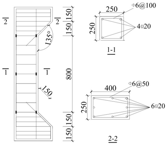
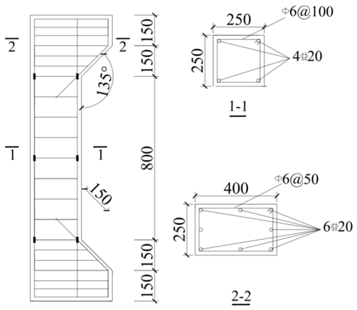
The end section dimensions of the cast-in-place columns, fabricated columns, and strengthened columns are 250 mm × 400 mm, with middle section dimensions of 250 mm × 250 mm and a height of 1400 mm. Corbels are designed at both ends of the specimens during the test to prevent local compression failure at the ends under eccentric loading. Four HRB400 steel bars with a diameter of 20 mm are adopted for the longitudinal reinforcement of the specimens, and HPB300 rectangular stirrups with a diameter of 6 mm are used as transverse reinforcement. These two types of steel bars are commonly used in China. A stirrup densified zone is set in the corbel part with a spacing of 50 mm, while the spacing in the non-densified zone is 100 mm. The concrete cover thickness of all specimens is 20 mm. The section dimensions and reinforcement layout of the specimens are shown in Figure 1.
Figure 1.
Section size and reinforcement diagram of the specimen.
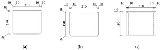
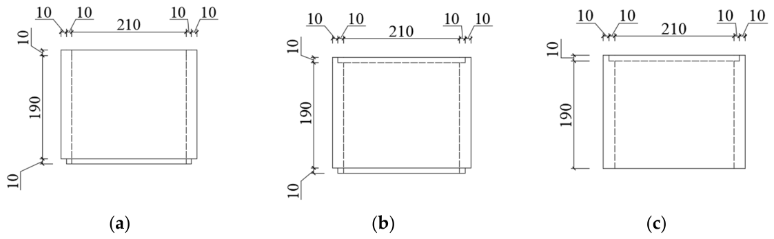
For eccentrically loaded fabricated reinforced concrete columns, formwork support is carried out using precast concrete modules, which are fabricated from four square-shaped modules with dimensions of 250 mm × 250 mm × 20 mm. Both ends of the precast modules are designed with a tongue-and-groove structure to ensure the connection performance between the precast modules. During the assembly of precast modules, cement slurry is applied at the tongue-and-groove joints, and cement slurry is also used for leveling after assembly to prevent grout leakage and enhance the connection between precast modules. After the precast modules are assembled, the inner surfaces of the modules are roughened with a steel brush to improve the bond between the precast modules and the core cast-in-place concrete. Figure 2 illustrates the configuration of the precast modules.
Figure 2.
Schematic diagram of precast modules: (a) top; (b) standard module; (c) bottom.
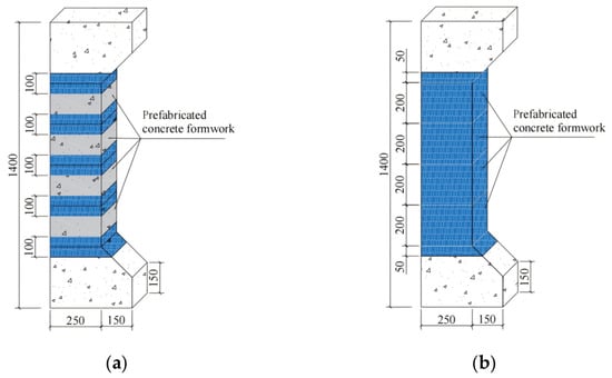
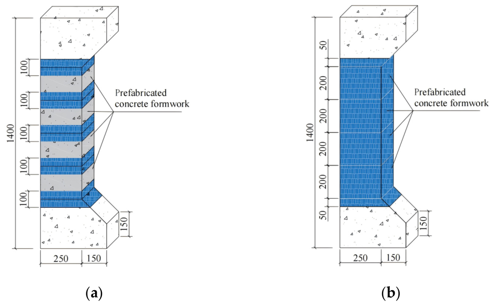
Fabricated reinforced concrete columns under eccentric compression were confined with 500 mm wide CFRP sheets, including full wrapping confinement and strip confinement, with a strip spacing of 100 mm for strip confinement. Meanwhile, to prevent premature failure at the joints between precast modules and post-cast concrete during loading, the joints at the corbels were all confined with CFRP sheets. Figure 3 presents the schematic diagram of the strengthened specimens.
Figure 3.
Section size and reinforcement diagram of specimen: (a) strip confinement; (b) full wrapping confinement.
Table 1 presents the specific numbering of the specimens. In the table, RC stands for cast-in-place columns, and PC stands for fabricated reinforced concrete columns. The abbreviation SE denotes small eccentric compression, while LE denotes large eccentric compression. CF stands for full wrapping confinement with CFRP sheets, and CS stands for strip confinement with CFRP sheets. The abbreviation PCCS stands for a fabricated reinforced concrete column with CFRP strip confinement. The abbreviation PCCF corresponds to a fabricated reinforced concrete column with CFRP full wrapping confinement.
Table 1.
Main parameters of concrete column specimens.
It should be noted that only one specimen was tested for each column configuration. This was primarily due to the substantial material preparation and fabrication time required for the precast reinforced concrete columns and the CFRP wrapping procedures. The large-scale nature of the specimens, together with limited laboratory capacity and the constraints of the project timeline, restricted the number of replicate specimens that could be produced. Furthermore, the main objective of this study was to conduct a comparative investigation across different confinement schemes and column types, which necessitated testing a wide range of configurations rather than repeating identical specimens. Although the existing experimental results reveal certain consistent behavioral patterns and provide valuable insights, the lack of replicated tests is acknowledged as a limitation. Future work will include repeated tests to further validate the findings and enhance statistical reliability.
2.2. Material Properties
The strength grades of the core concrete of the fabricated reinforced concrete columns and the concrete of the cast-in-place columns were both C40. Eight columns were poured with concrete of the same batch, and a group (three pieces) of 150 mm × 150 mm × 150 mm standard cubic test blocks were reserved simultaneously and cured under the same conditions. The concrete for manufacturing precast modules was fine aggregate concrete, and a group of standard cubic test blocks were correspondingly reserved for curing. The tensile failure test of steel bars was carried out on a computer-controlled servo testing machine. The concrete cube compressive strength test was carried out in accordance with Chinese Standard GB/T 50081-2019 [30]. Using the measured cube compressive strength fcu,m, the mechanical property parameters such as the axial compressive strength fcm, axial tensile strength ftm, and elastic modulus Ec are calculated by Equations (1)–(3) given as standard, and then adopted as the parameters in the finite element model.
where fcu,m represents the average value of the measured compressive strength of concrete cubes. fcm represents the calculated value of the axial compressive strength of concrete. ftm αc1 represents the calculated value of the axial tensile strength of concrete. αc1 represents the ratio of prism strength to cube strength. Ec represents the calculated value of the elastic modulus of concrete.
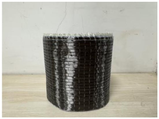
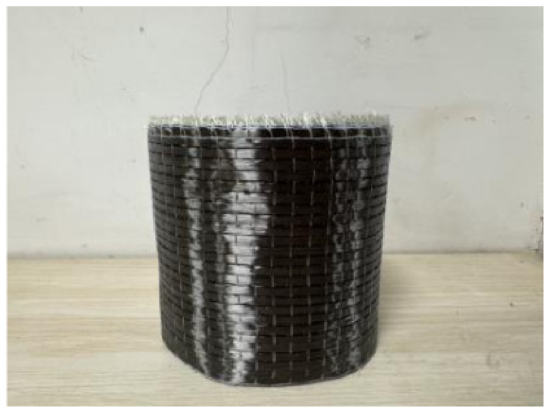
The tensile failure test of steel bars was carried out on a computer-controlled servo testing machine. The parameters of Grade I 300 g unidirectional fabric CFRP sheets are based on the quality inspection report and material property test report provided by the manufacturer (Figure 4). The performance parameters of various materials are as shown in Table 2, Table 3 and Table 4.
Figure 4.
CFRP sheets.
Table 2.
Concrete material performance parameters.
Table 3.
Performance parameters of steel material.
Table 4.
CFRP cloth material performance parameters.
2.3. Loading System
The specimens were loaded by controlling the displacement rate. Except for specimens under large eccentric compression, other specimens were loaded at a rate of 0.4 mm/min. After the specimens were loaded to 80% of the peak load, the loading rate was adjusted to 0.2 mm/min. For specimens under large eccentric compression, considering that the lateral displacement during the test is larger than that of small eccentric compression columns and the bearing capacity would decrease, a loading rate of 0.1 mm/min was adopted throughout the process. When the column exhibited obvious failure phenomena, underwent significant deformation, or experienced a sudden drop in bearing capacity, the specimen was taken as damaged, and the testing process was concluded.
3. Finite Element Model Setup for Specimens
3.1. Finite Element Analysis and Calculation
In ABAQUS finite element analysis, ABAQUS/Standard must determine the solution of nonlinear problems through iterations, offering high accuracy and efficiency but being prone to convergence difficulties. In contrast, ABAQUS/Explicit determines the solution without iteration by explicitly advancing the dynamic state based on the results of the previous increment; however, the computational results are heavily dependent on the time step, requiring substantial computational time and storage space. Therefore, this study adopts the ABAQUS/Standard module to analyze the compressive behavior of precast reinforced concrete columns confined with CFRP sheets.
3.2. Material Constitutive Relations
3.2.1. Concrete Material Constitutive Model
According to the strength of the constraint effect of steel bars on concrete, the fabricated reinforced concrete columns are divided into constraint regions, and the concrete is divided into two regions: unconfined concrete and confined concrete zone, corresponding to the concrete outside and inside the stirrups, respectively, and different compressive stress–strain constitutive relationships are adopted.
The unconfined concrete adopts the uniaxial compressive constitutive relationship in Chinese Code GB/T 50010-2010 [31], as seen in Equation (4).
where represents the elastic modulus of concrete (MPa), and represents the uniaxial compressive damage parameter of concrete (MPa).
The confined concrete within the stirrups adopts the Mander constitutive model [2], seen in Equation (5):
where , represents the peak strain of confined concrete, . , represents the elastic modulus of concrete. represents the secant modules of confined concrete. represents the compressive strength of confined concrete. represents the unconfined concrete strain, usually taken as 0.002. represents the unconfined compressive strength of concrete.
The constitutive relationship of concrete in tension adopts the uniaxial tensile stress–strain relationship [31], as shown in Equation (6):
where represents the uniaxial tensile damage parameter of concrete, which characterizes the stiffness degradation of concrete under tension.
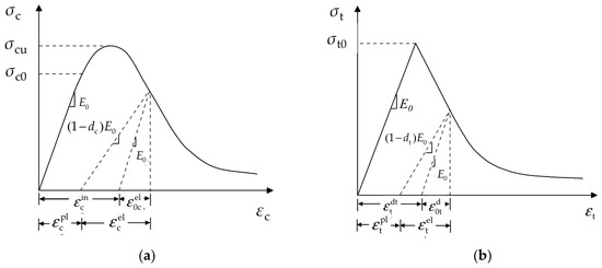
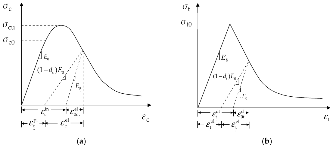
The concrete stress–strain relationship curve cannot be directly applied in ABAQUS; it must be converted into the stress–strain relationship curve within the concrete constitutive model provided by ABAQUS. Since this study focuses on the compressive performance of CFRP sheet-confined fabricated reinforced concrete columns under uniaxial load, the plastic damage model is appropriate because it comprehensively accounts for the convergence, computational accuracy, and efficiency of the model (Figure 5). The parameter values are listed in Table 5.
Figure 5.
Damage curves of concrete under uniaxial compression and tension: (a) uniaxial compression confinement; (b) uniaxial tension.
Table 5.
Parameter values of concrete damage plasticity model.
Since the stiffness degradation of concrete in tensile and compressive damage is inconsistent, the tensile damage factor dt and compressive damage factor dc in the code are introduced to describe the stiffness degradation of both. According to the tensile and compressive damage curves, ABAQUS uses an automatic relationship to convert cracking strain into plastic strain values, with the specific relational expressions shown in Equations (7) and (8).
in which represents tensile plastic strain, represents tensile inelastic strain, represents tensile elastic strain under initial stiffness, and represents the tensile damage factor.
where represents compressive plastic strain, represents compressive inelastic strain, represents compressive elastic strain under initial stiffness, and represents the compressive damage factor.
By simply specifying the relationship under tension and the relationship under compression, the built-in ABAQUS program will automatically complete the conversion between and .
3.2.2. Concrete Constitutive Model
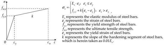
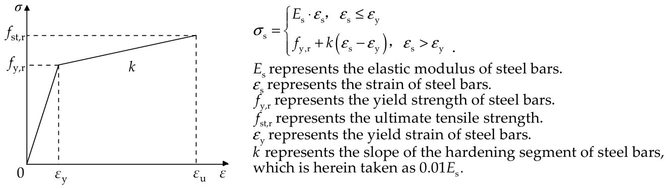
The defined property of steel bars in ABAQUS is an elasto-plastic model. Therefore, the material constitutive relationship of steel bars in the model of this study adopts a bilinear model, and the schematic diagram of its plot of stress against strain and the relational expression are shown in Figure 6.
Figure 6.
Stress–strain curve of the steel bars.
3.2.3. CFRP Sheet Constitutive Model
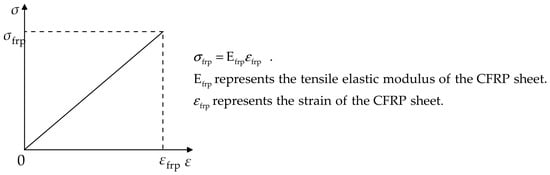
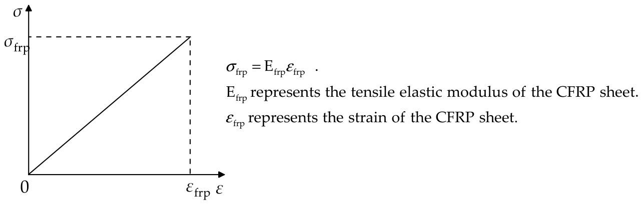
In the simulation analysis, the CFRP sheet is an anisotropic material, and only the tensile stress on the CFRP sheet is considered. When the ultimate tensile strain is reached, it is considered to have fractured and failed. Therefore, the linear elastic model is used to define its properties, and the stress–strain curve and relational expression are shown in Figure 7.
Figure 7.
Stress–strain curve of the CFRP sheet.
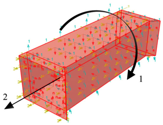
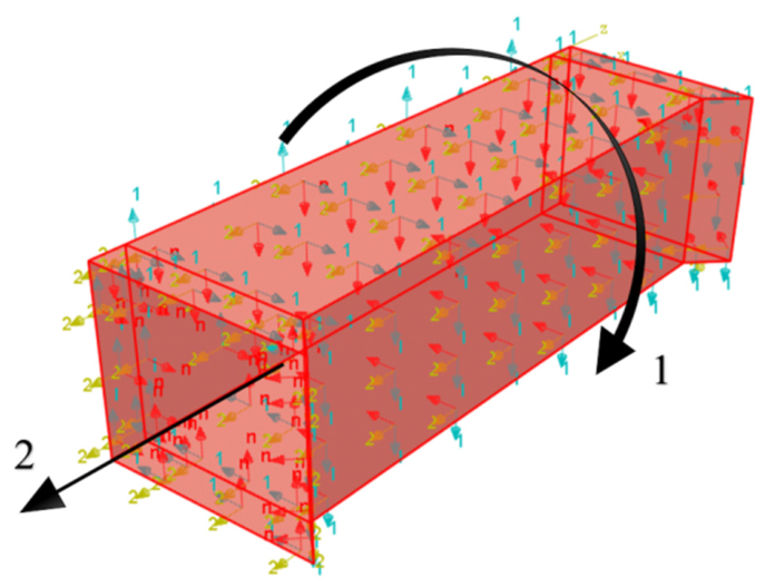
The ABAQUS software provides a model for defining the orthotropy of fiber materials (lamina). The definition of the material direction of the fiber layer in this paper is shown in Figure 8, in which the direction 1 and direction 2 are respectively the circumferential and axial directions for the installation of CFRP. The local coordinate system adopts a cylindrical coordinate, where directions 1 and 2 correspond to the circumferential and axial directions of the CFRP sheet bonded and laid, respectively. The parameters of this model can be set according to the material property parameters of the CFRP sheet.
Figure 8.
CFRP material direction.
3.3. Interactions
Since no obvious slip phenomenon was observed between the fabricated templates, steel bars, CFRP sheets, and concrete during the test, the model assumes that the core area concrete is perfectly bonded with the fabricated templates, steel bars, and CFRP sheets. For cast-in-place columns, there is only contact between concrete and steel bars. For fabricated columns, in addition to embedding the steel skeleton into the entire model, it is necessary to set the contact relationship between the concrete column, fabricated templates, and CFRP sheets.
3.3.1. Steel Bar–Concrete Column Interaction
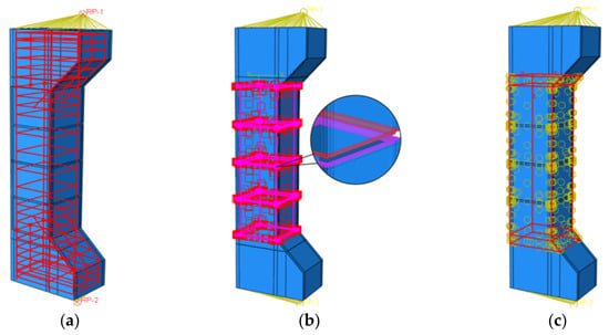
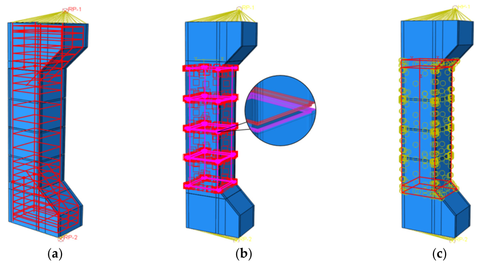
When the bond-slip between concrete and steel bars is not considered, the steel skeleton composed of longitudinal bars and stirrups is embedded into the concrete column through the embedded constraint relationship, thereby effectively achieving the synergistic deformation effect between the concrete and steel bars, as shown in Figure 9a.
Figure 9.
Interaction between components. (a) Embedded constraint. (b) Surface-to-surface contact. (c) Tie constraint.
3.3.2. Contact Relationship Between Fabricated Templates and Core Cast-in-Place Concrete
Regarding the contact at the joints between fabricated templates and between the inner surface of the templates and the cast-in-place concrete, surface-to-surface contact is used for definition to simplify calculations. The equivalent friction method is selected to simulate the interface contact between new and old concrete, as illustrated in Figure 9b. In this method, Coulomb friction force is employed to simulate the tangential force between new and old concrete, and the bond performance between them is defined by setting the magnitude of the interface friction coefficient, with the friction coefficient taken as 1. For the normal interaction between new and old concrete, hard contact is adopted to simulate the normal action, meaning that new and old concrete are allowed to separate after detachment.
3.3.3. Interaction Between CFRP Sheets and Concrete
CFRP sheets are bonded to concrete through impregnating adhesive. To facilitate the handling of the contact effect between concrete and CFRP sheets, the effect of structural adhesive is usually not considered. A tie constraint is used to bind to the concrete surface, so that there is no relative movement between the two different units, as shown in Figure 9c.
3.4. Boundary Conditions and Loading Method
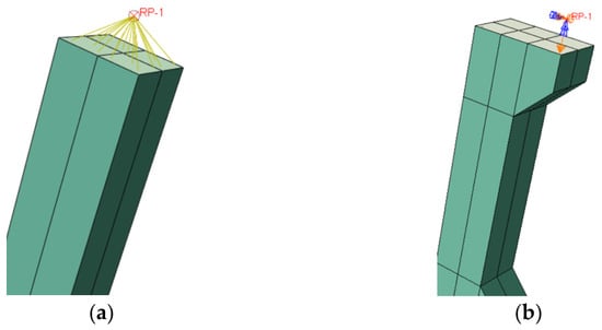
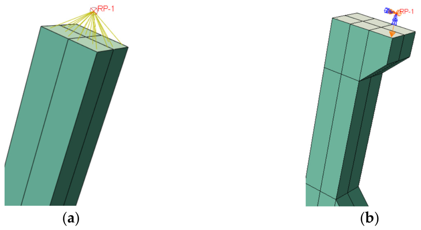
Loading reference points were created at the top and bottom surfaces of the column, and each reference point was coupled to the corresponding surface using a coupling constraint, as shown in Figure 10a. To closely replicate the experimental loading conditions, displacement-controlled loading was adopted. For the concentrically loaded column, the bottom end was fully fixed (U1 = U2 = U3 = UR1 = UR2 = UR3 = 0), while the top end was restrained against translations in the X and Z directions and rotations about the X, Y, and Z axes (U1 = U3 = 0, UR1 = UR2 = UR3 = 0). For the eccentrically loaded column, both ends were pinned: the bottom end was fixed against translations in the X, Y, and Z directions and rotations about the X and Y axes (U1 = U2 = U3 = 0, UR1 = UR2 = 0), and the top end was restrained against translations in the X and Z directions and rotations about the X and Y axes (U1 = U3 = 0, UR1 = UR2 = 0), as illustrated in Figure 10b.
Figure 10.
Boundary conditions and bearing constraint diagram. (a) Coupling of the column top (bottom) surface to the reference point. (b) Support constraints and loading arrangement.
3.5. Model Establishment and Mesh Division
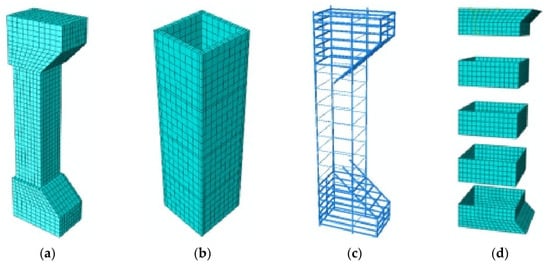
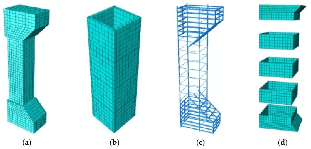
In this simulation, the concrete column and templates are modeled using the eight-node reduced integration 3D solid element C3D8R. Longitudinal bars and stirrups are modeled using the two-node linear 3D truss element T3D2. CFRP sheets are modeled using the four-node reduced integration 3D membrane element M3D4R. The models in this study are all 3D solids with relatively regular shapes. Therefore, structured mesh division is adopted to generate hexahedral elements. The concrete column, fabricated panels, and steel skeleton are divided into elements of 30 mm, while the CFRP sheets are divided into elements of 25 mm. The mesh convergence analysis confirms that the adopted mesh density has no appreciable influence on the numerical results, ensuring the stability and reliability of the solution. The mesh division of each component is shown in Figure 11.
Figure 11.
Mesh division of each component. (a) Core concrete. (b) Fabricated concrete templates. (c) Stirrups and longitudinal bars. (d) CFRP sheets.
4. Model Validation
Finite element model results usually differ from experimental phenomena: (1) The finite element model adopts an ideal material model, while the properties of materials such as steel bars and concrete in actual components are affected by factors like initial defects and construction quality. (2) In finite element models, loads or displacements are usually applied directly at both ends of the specimen, whereas actual specimens have loading devices at both ends, which deform during the test, leading to changes in the stress state of the specimen. (3) The contact and constraint conditions in the finite element model cannot be completely identical to those of actual components. Therefore, this finite element model can be used to simulate the entire loading process of the compressive performance of CFRP sheet-confined fabricated concrete columns.
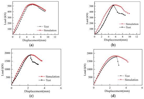
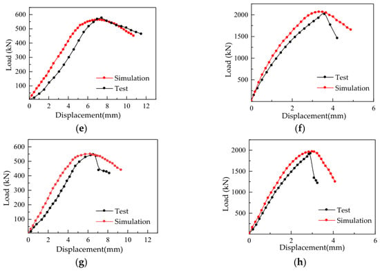
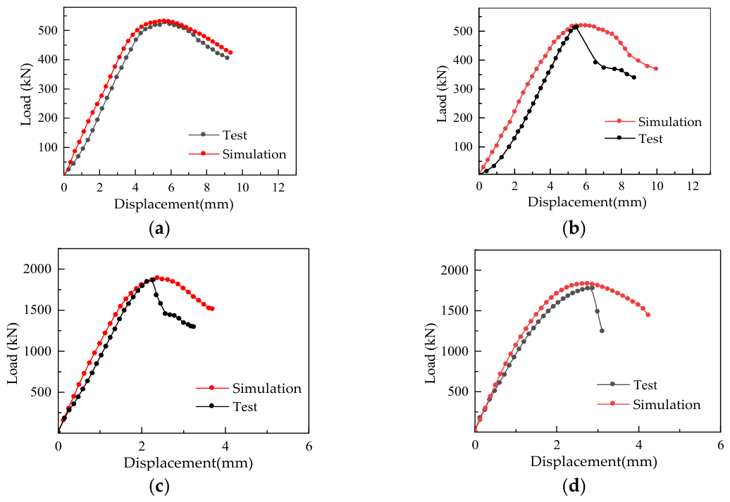
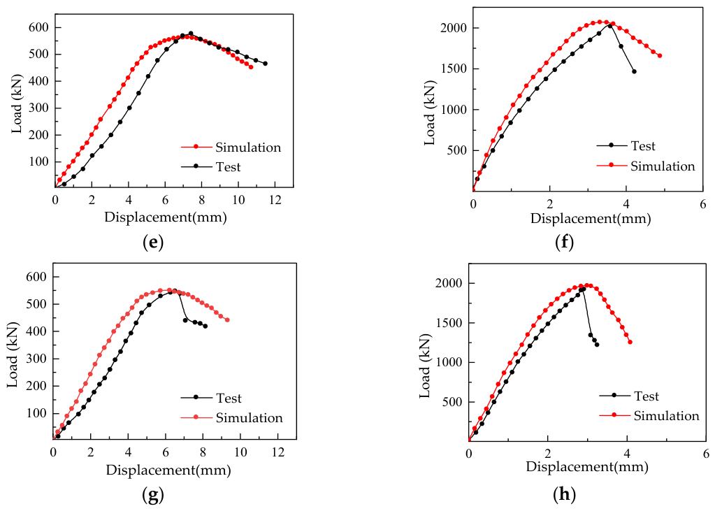
Table 6 shows the comparison of ultimate bearing capacity between the test results and finite element simulation results of eccentric compression columns. As shown in the table, the simulation results of ultimate bearing capacity are in good agreement with the test data, and the error is below 3%.
Table 6.
Comparison of ultimate bearing capacity of eccentric compression column test and model.
As illustrated in Figure 12, the ascending segment of the load–displacement curves for the simulated and test specimens of eccentric compression columns follows a basically similar trend, but the loading curves of the fabricated columns show certain discrepancies in the descending segment. This is because in the finite element model, loads or displacements are usually applied directly at both ends of the specimen, whereas actual specimens have loading devices (steel plates) at both ends. The steel plates deform during the test. After reaching the ultimate bearing capacity, the specimen fails, and the steel plates undergo stress release and rebound, leading to changes in the stress state of the specimen. Therefore, after the peak load, a sudden downward trend is observed.
Figure 12.
Comparison of load–displacement curves of eccentric compression column test and model. (a) RC-LE. (b) PC-LE. (c) RC-SE. (d) PC-SE. (e) PCCF-LE. (f) PCCF-SE. (g) PCCS-LE. (h) PCCS-SE.
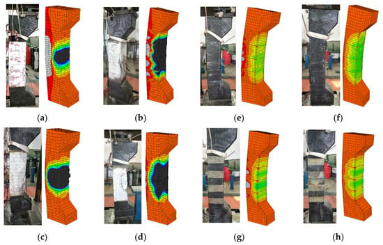
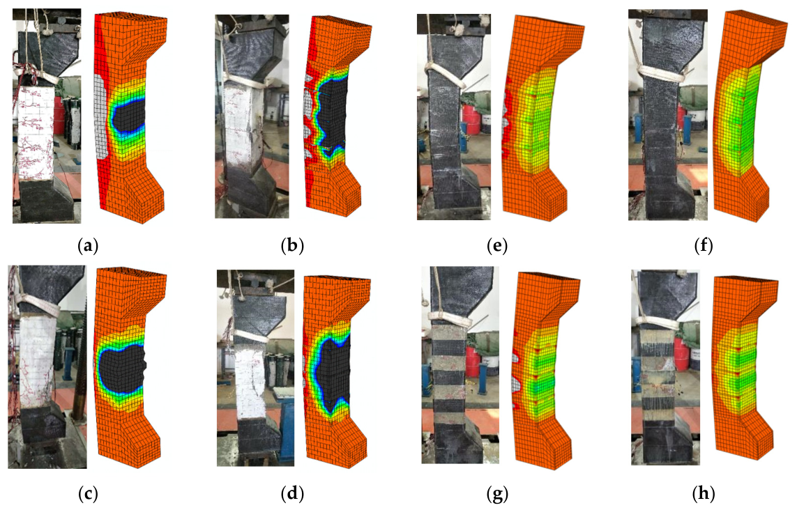
Figure 13a–h show the comparison of failure modes between the test data and finite element model analysis results of the specimens. As can be seen from the figures, the failure modes of the finite element model and the test specimens are basically the same, both conforming to the failure characteristics of eccentric compression columns. Based on the above analysis, it can be verified that using this model to study the eccentric compression performance of cast-in-place and fabricated reinforced concrete columns is feasible and accurate.
Figure 13.
Failure mode comparison diagrams of eccentric compression column test and model. (a) RC-LE. (b) PC-LE. (c) RC-SE. (d) PC-SE. (e) PCCF-LE. (f) PCCF-SE. (g) PCCS-LE. (h) PCCS-SE.
5. Parameter Analysis
To further investigate the effects of different factors on the compressive performance of CFRP sheet-confined fabricated concrete columns, this paper, based on the aforementioned finite element analysis model, studies the influences of factors such as fabricated concrete column damage, CFRP sheet layers, strip width, net spacing, and concrete strength on the compressive mechanical properties of fabricated concrete columns.
5.1. Model Design
5.1.1. Layers, Strip Width, and Spacing of CFRP Sheet
Based on the CFRP sheet-confined column model, 54 eccentric compression columns were designed with concrete strength grades C40 and C30. The thickness of the CFRP sheet is 0.167 mm, and the number of layers is set to 1, 2, 3, and 4. The eccentricities are 200 mm and 40 mm.
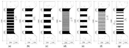
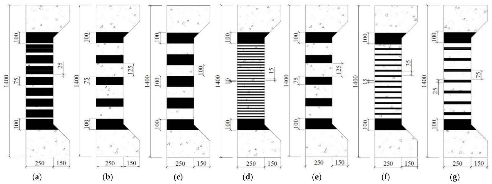
For the selection of CFRP strip width and net spacing, since the research object is an eccentric column, the adjacent joints of fabricated templates are structurally weak. To ensure the overall stability of the specimens, CFRP sheets are bonded at the joints between corbels and templates with a strip width of 100 mm. CFRP sheets are bonded at each template joint, and additional CFRP sheets are evenly bonded in the gaps. The strip widths used are 125 mm, 100 mm, 75 mm, 50 mm, 25 mm, 15 mm, and 10 mm. Since the net spacing changes with the strip width, there are many combinations of strip width and net spacing, which can easily result in the same constraint amount. To better describe the constraint amount of the specimens, the CFRP strip strengthening ratio ks is introduced, defined as the ratio of the strip width to the sum of the net spacing and strip width. The values of ks are 0, 0.25, 0.3, 0.38, 0.4, 0.5, 0.63, 0.75, and 1, respectively. The CFRP strip bonding scheme of the specimens is shown in Figure 14.
Figure 14.
Scheme diagrams of different carbon fiber cloth pastes (ks). (a) 0.75. (b) 0.63. (c) 0.5. (d) 0.4. (e) 0.38. (f) 0.3. (g) 0.25.
5.1.2. Strengthening of Damaged Columns
The width and net spacing of CFRP sheets, number of layers, reinforcement ratio, and concrete strength grade of the specimens were kept constant. The damage levels of the specimens were set as 0.3, 0.35, 0.4, 0.45, and 0.5 times the peak bearing capacity of the unstrengthened specimens. Among these specimens, the CFRP sheet arrangement of the simulated specimens was one layer of full wrapping strengthening, with concrete strength grades C30 and C40, a single-layer CFRP sheet thickness of 0.167 mm, and eccentricities of 200 mm and 40 mm.
5.2. Analysis of the Influence of CFRP Sheet Layers on Compressive Performance of Fabricated Columns
5.2.1. Ultimate Bearing Capacity Analysis
Table 7 shows the ultimate bearing capacity values of fabricated eccentric compression columns confined with different layers of CFRP sheets. In the table, the “increase amplitude” refers to the change in ultimate bearing capacity of specimens confined with different CFRP sheet layers relative to unconfined specimens, and the “relative increase rate” refers to the ratio of the increment in ultimate bearing capacity of the current layer-confined specimen to the ultimate bearing capacity of the previous layer-confined specimen.
Table 7.
Ultimate bearing capacity of fabricated large eccentric compression columns confined with different layers of CFRP sheets.
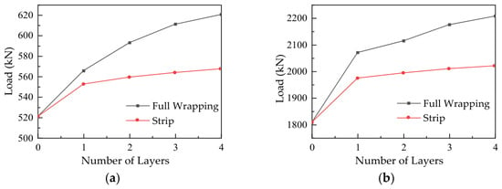
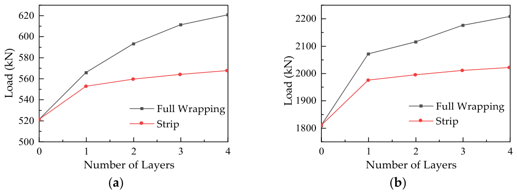
It can be seen from the data in the table that for both fabricated large and small eccentric compression columns, after being strengthened with CFRP sheets, the ultimate bearing capacity increases with the increase in the number of layers, and the full wrapping confinement effect is always better than the strip confinement effect. Specifically, for large eccentric compression columns, full wrapping with 1–4 layers of CFRP sheets increases the bearing capacity by 8.62% to 19.18%. For small eccentric compression columns, the increase amplitude under the same number of layers is 14.52% to 22.12%. In comparison, the strengthening effect of small eccentric compression columns is more significant, which is due to the fact that CFRP sheets can more effectively constrain lateral deformation, thereby enhancing the bearing performance to a greater extent.
As the number of CFRP sheet strengthening layers increases, the increase amplitude of ultimate bearing capacity shows a decreasing trend. For example, for large eccentric compression specimens with full wrapping strengthening, when the number of layers increases from 1 to 4, the increase rate per layer gradually decreases from 4.84% to 1.54%. Small eccentric compression specimens also show a similar pattern. This indicates that the synergistic working capacity of CFRP sheets weakens during multi-layer strengthening, and the strength utilization rate gradually decreases. Therefore, the strengthening effect does not increase linearly with the number of layers, but there is a reasonable range. This can also be seen from Figure 15a,b.
Figure 15.
Variation in ultimate bearing capacity of fabricated reinforced concrete columns with number of CFRP sheet layers. (a) Large eccentric compression. (b) Small eccentric compression.
Based on the comprehensive research results, it is recommended that the number of CFRP sheet layers in practical applications be preferably 2–3 layers. Beyond this range, continuing to increase the number of layers will no longer significantly improve the bearing capacity.
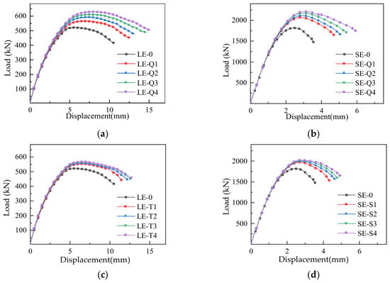
5.2.2. Load–Displacement Curve Analysis
The load–displacement curves in Figure 16 show that with the increase in the number of CFRP sheet strengthening layers, the ultimate displacement of the specimens increases significantly, and the deformation capacity is enhanced. This is because the confinement effect of the CFRP sheets is fully exerted mainly after the peak load. It restrains the lateral expansion of concrete, increases the ultimate compressive strain, and thereby delays the failure process and improves the ductility of the specimens.
Figure 16.
Load–displacement curves of fabricated columns confined with different layers of CFRP sheets. (a) LE-F. (b) SE-F. (c) LE-S. (d) SE-S.
Specifically, for small eccentric compression specimens, CFRP sheet confinement (especially the full wrapping form) can make the descending segment of the curve gentler, significantly improving ductility. However, for large eccentric compression specimens, although the bearing capacity is improved, the effect of using only transverse CFRP sheet confinement to improve ductility is limited, indicating that the strengthening method has an insignificant effect on improving the deformation performance of large eccentric compression columns.
5.2.3. Failure Mode Analysis
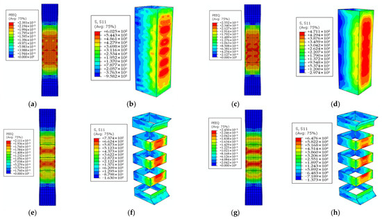
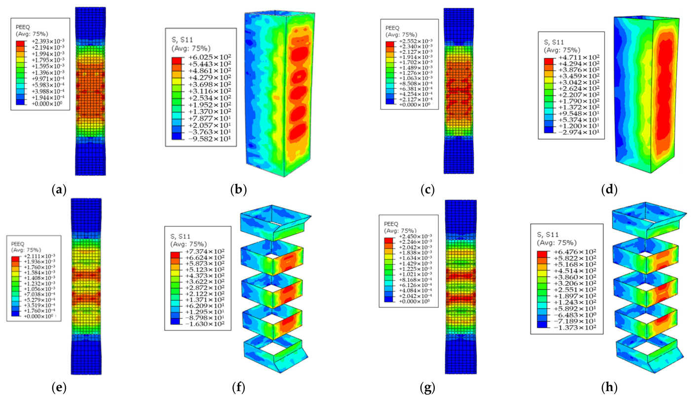
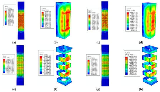
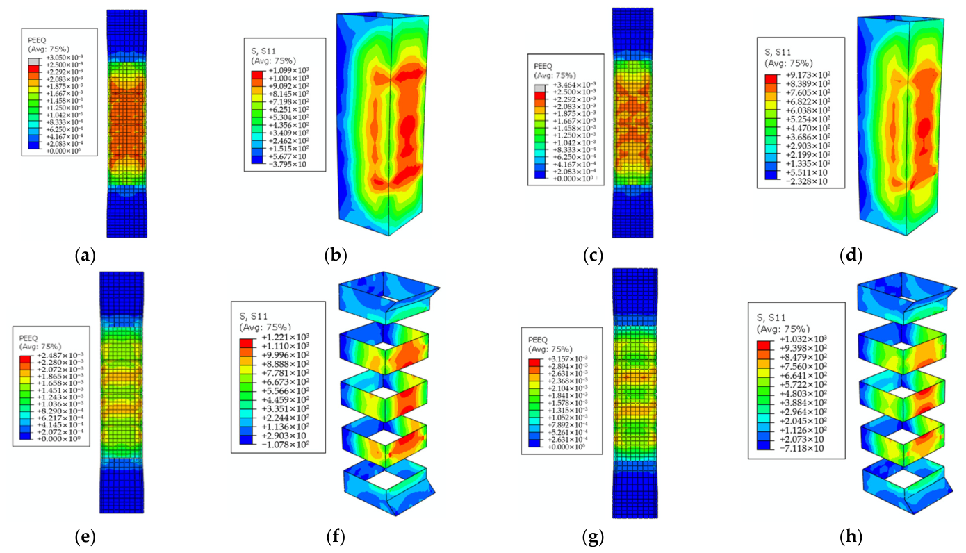
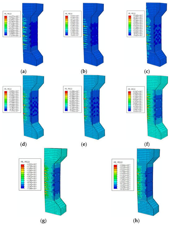
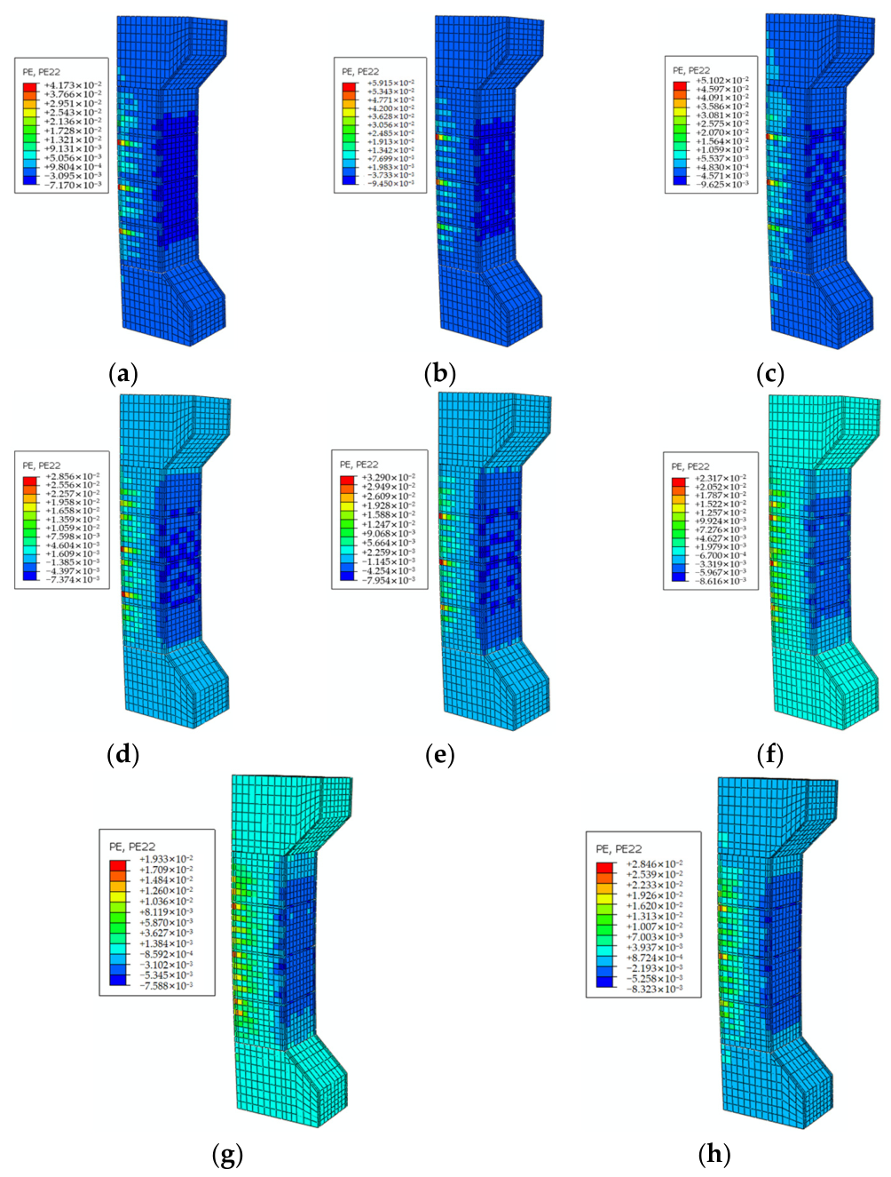
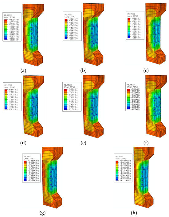
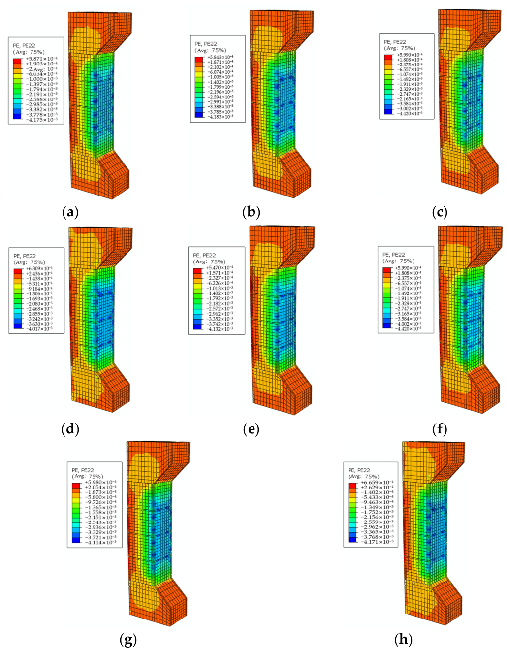
As mentioned earlier, the improvement effect of CFRP sheets on bearing capacity is no longer significant when the number of layers exceeds three. Figure 17 and Figure 18, through finite element simulation, respectively show the concrete equivalent plastic strain and CFRP sheet stress distribution of fabricated large and small eccentric compression columns strengthened with two and three layers of CFRP sheets when reaching ultimate bearing capacity. The analysis indicates that an increase in the number of CFRP sheet layers leads to a significant rise in the concrete equivalent plastic strain within the compression zone of the specimen, an expansion of the compression zone height, and a tendency toward uniformity in the compressive stress distribution. This phenomenon is particularly obvious in fully wrapped strengthened specimens, whose stress uniformity is better than that of strip strengthened specimens. The reason is that full wrapping provides continuous and complete confinement, while the confinement effect of strip strengthening is uneven at the strip gaps.
Figure 17.
Equivalent plastic strain of concrete and stress nephograms of CFRP sheets for two-layer and three-layer fabricated columns under large eccentric compression. (a) LE-F2. (b) LE-F2 CFRP. (c) LE-F3. (d) LE-F3 CFRP. (e) LE-S2. (f) LE-S2CFRP. (g) LE-S3. (h) LE-S3 CFRP.
Figure 18.
Equivalent plastic strain of concrete and CFRP stress nephograms of two-layer and three-layer CFRP sheet confined fabricated small eccentric compression columns. (a) SE-F2. (b) SE-F2 CFRP. (c) SE-F3. (d) SE-F3 CFRP. (e) SE-S2. (f) SE-S2 CFRP. (g) SE-S3. (h) SE-S3 CFRP.
From the stress nephogram of CFRP sheets, it can be found that the stress is mainly concentrated in the compression zone of the specimen, reflecting that the concrete deformation and confinement demand in this area are the largest. It is worth noting that with the increase in the number of CFRP sheet layers, its own stress level shows a downward trend. At the same time, the crack development in the concrete is denser and more sufficient. This seemingly contradictory phenomenon precisely indicates that increasing the number of layers effectively improves the overall confinement stiffness of the composite, allowing the high-strength performance of CFRP sheets to be more fully exerted, thereby maintaining high bearing capacity even after concrete cracking and failure process delay. Therefore, the simulation results confirm from the perspective of micromechanics that increasing the number of CFRP sheet layers can effectively improve the bearing performance and ductility of fabricated columns by improving stress distribution and enhancing the confinement effect. The numerical values in the figure represent the stress at the response location.
5.3. Analysis of the Influence of CFRP Sheet Width and Net Spacing on the Compressive Performance of Fabricated Columns
5.3.1. Analysis of Ultimate Bearing Capacity
The simulation data in Table 8 show that the width and net spacing of CFRP strips have a significant influence on the ultimate bearing capacity of fabricated columns. When strip strengthening is only applied at the joints of the fabricated formwork, the ultimate bearing capacity of both large and small eccentric compression specimens decreases with the reduction in strip width.
Table 8.
Ultimate bearing capacity of fabricated columns with different width and spacing of CFRP sheets.
Controlling the net spacing of strips to be the same, the ultimate bearing capacity of the specimens increases with the increase in strip width. Meanwhile, the comparative data reveal that for the same strip width, the bearing capacity of the specimens declines when the strip net spacing becomes larger. Wider strips and smaller net spacing can provide more effective confinement, thereby achieving a better strengthening effect.
When the confinement ratio ks of the specimen is 0.5, the strip width and net spacing are 100 mm, 50 mm, 25 mm, and 10 mm, respectively. When the strip width decreases from 100 mm to 25 mm, the ultimate bearing capacity decreases with the reduction in CFRP strip width and net spacing. However, when the CFRP strip width decreases to 10 mm, the ultimate bearing capacity reaches the maximum. The reason is that the smaller the net spacing between adjacent CFRP sheets, the stronger the confinement effect on concrete. If only reducing the net spacing between CFRP strips is considered while ignoring the strip width, the CFRP sheets will break due to excessive tensile stress during loading, losing the confinement effect on concrete.
Based on the above analysis, when the CFRP strip width is constant, reducing the net spacing between strips leads to an increase in the ultimate bearing capacity of the specimen. When the CFRP net spacing is constant, the ultimate bearing capacity increases with the increase in strip width. The ultimate bearing capacity increases with the confinement ratio, but the improvement amplitude is small, indicating that an appropriate CFRP sheet arrangement should be selected for confinement.
5.3.2. Load–Displacement Curve Analysis
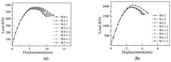
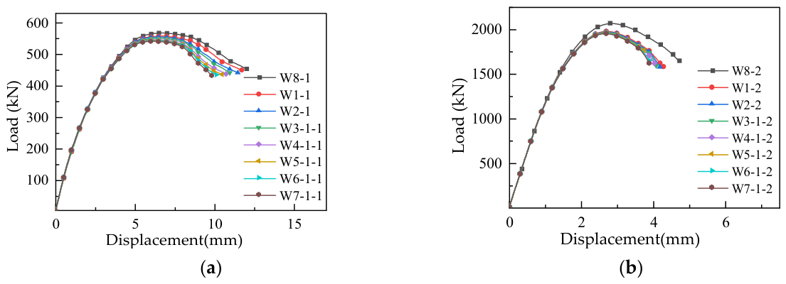
Figure 19 shows the load–displacement curves of fabricated large and small eccentric compression columns with different CFRP strip widths and net spacings. It can be seen that in the elastic stage, the curves remain almost unchanged because the concrete does not undergo significant deformation in the initial loading stage, and the CFRP sheets do not exert passive confinement. When the specimens enter the plastic deformation stage, the slopes of the curves begin to differ because the specimen deformation increases significantly, activating the CFRP confinement effect. As the CFRP strip width and confinement ratio decrease, the confinement effect on the concrete weakens, leading to a gradual reduction in the ultimate bearing capacity of fabricated large and small eccentric compression columns, with no significant improvement in ductility.
Figure 19.
Load–displacement curves of fabricated columns with different widths and spacings of CFRP sheets. (a) Large eccentric. (b) Small eccentric.
5.3.3. Failure Mode Analysis
Figure 20 shows the influence of CFRP strip width variation on the failure mode of large eccentric compression members when the net spacing is fixed. The results show that as the strip width decreases, the concrete cracks on the tensile side tend to be dense, while the non-uniformity of compressive strain distribution and plastic strain of concrete on the compressive side both increase. This is mainly because although the narrowing of strips increases the number of strips, the direct confinement area decreases, which easily leads to stress concentration at the formwork corners, resulting in a reduction in the confinement effect.
Figure 20.
The failure modes of fabricated large eccentric compression columns with different widths and spacing of CFRP sheets. (a) W3-21. (b) W5-21. (c) W6-31. (d) W4-31. (e) W5-31. (f) W7-31. (g) W6-41. (h) W7-41.
Comparison of specimens with the same width and different net spacings reveals that when the strip width is constant, reducing the net spacing leads to a further increase in cracks on the tensile side, while making the compressive stress distribution on the compressive side more uniform and increasing the height of the compressive zone. This indicates that reducing the net spacing can effectively increase the confinement ratio, thereby enhancing the confinement effect of CFRP sheets on concrete and improving the bearing capacity of the member.
Figure 21 shows the failure modes of small eccentric compression members with different CFRP strip widths under fixed net spacing. As shown in Figure 21a, when the net spacing is 25 mm, the strip widths of W3-2, W5-2, and W6-3 are 75 mm, 25 mm, and 15 mm, respectively. It can be observed that under the same net spacing, the plastic strain of concrete in the compressive zone increases as the strip width decreases. A small amount of strain appears in the tensile zone, indicating fewer and narrower cracks in the tensile zone. Comparing specimens W5-22 and W5-32, under the same strip width, the smaller the net spacing, the smaller the concrete strain in the compressive zone. This is because more strengthening strips (higher strengthening ratio) result in more confinement applied to the concrete in adjacent net spacing, enabling it to bear higher pressure.
Figure 21.
The failure modes of fabricated small eccentric compression columns with different widths and spacing of CFRP sheets. (a) W3-22. (b) W5-22. (c) W6-32. (d) W4-32. (e) W5-32. (f) W7-32. (g) W6-42. (h) W7-42.
5.4. Analysis of the Influence of CFRP Sheet Strengthening on Compressive Performance of Damaged Fabricated Columns
5.4.1. Ultimate Bearing Capacity Analysis
The damage degree was defined as follows: while the CFRP sheet width, clear spacing, number of layers, reinforcement ratio, and concrete strength grade of the specimens were kept constant, different damage levels were set as 0.3, 0.35, 0.4, 0.45, and 0.5 times the peak bearing capacity of the unreinforced control specimen.
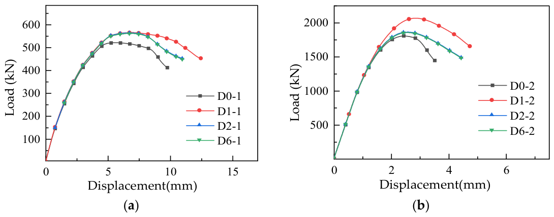
In Table 9, finite element simulation results show that after strengthening with CFRP sheets, the ultimate bearing capacity of damaged fabricated columns with different damage degrees is significantly improved. Moreover, with the increase in damage degree, the ultimate bearing capacity only shows a limited decrease. For small eccentric compression specimens, when the damage degree increases from 0.3 to 0.5, its ultimate bearing capacity slightly decreases from 1863.70 kN to 1858.27 kN, with a small reduction range. For large eccentric compression specimens, when the damage degree is in the range of 0.3 to 0.5, the ultimate bearing capacity slightly decreases from 564.11 kN to 561.67 kN. Overall, the increase in damage degree has little influence on the ultimate bearing capacity of the strengthened columns, and the strengthening effect of CFRP on damaged columns is stable and significant.
Table 9.
Ultimate bearing capacity of CFRP-reinforced and damaged fabricated large-biased columns.
5.4.2. Load–Displacement Curve Analysis
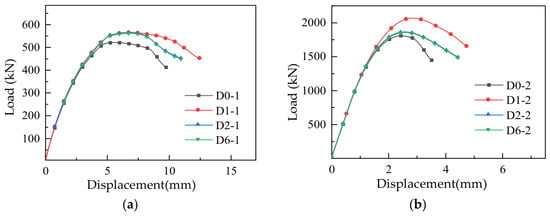
From the load–displacement curves of the specimens presented in Figure 22, the following conclusions are obtained. Since the initial strengthening load is applied before the member reaches the peak strain, the damaged fabricated reinforced concrete columns strengthened with CFRP sheets can be repaired. The bearing capacity and stiffness can return to the undamaged state, and the downward trend slows down after reaching the peak load. Compared with undamaged fabricated reinforced concrete columns, the bearing capacity of damaged strengthened columns is improved after CFRP sheet strengthening, and the improvement amplitude is slightly larger for members with smaller bearing capacity. This is because the confinement effect of transverse CFRP sheets increases the compressive strain of concrete and enhances its bearing capacity. The high tensile strength and elastic modulus of CFRP sheets are fully utilized, leading to ductile failure of the eccentric compression column. Meanwhile, it can be seen from the figure that the damage degree has a greater impact on the bearing capacity of small eccentric compression columns.
Figure 22.
Load–displacement curve of damaged fabricated columns strengthened with CFRP sheets. (a) Large eccentric. (b) Small eccentric.
5.4.3. Failure Mode Analysis
The compressive damage variable is defined as a scalar index representing the stiff degradation of concrete under compression, ranging from 0 (undamaged state) to 1 (fully damaged state).
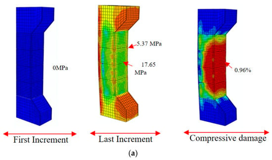
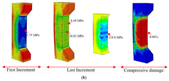
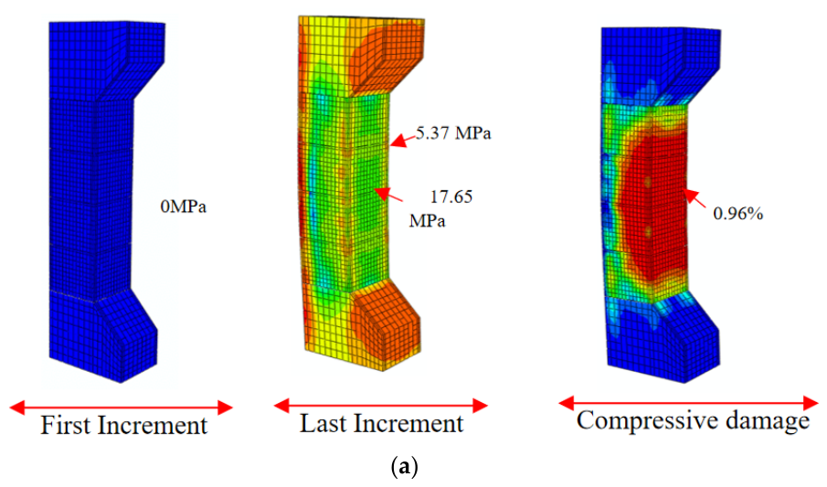
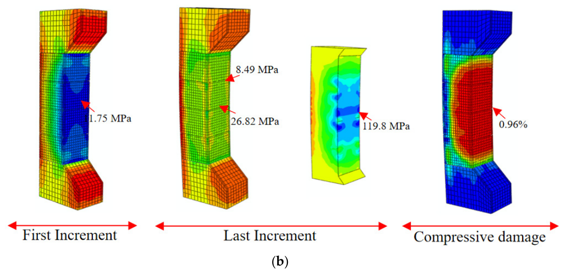
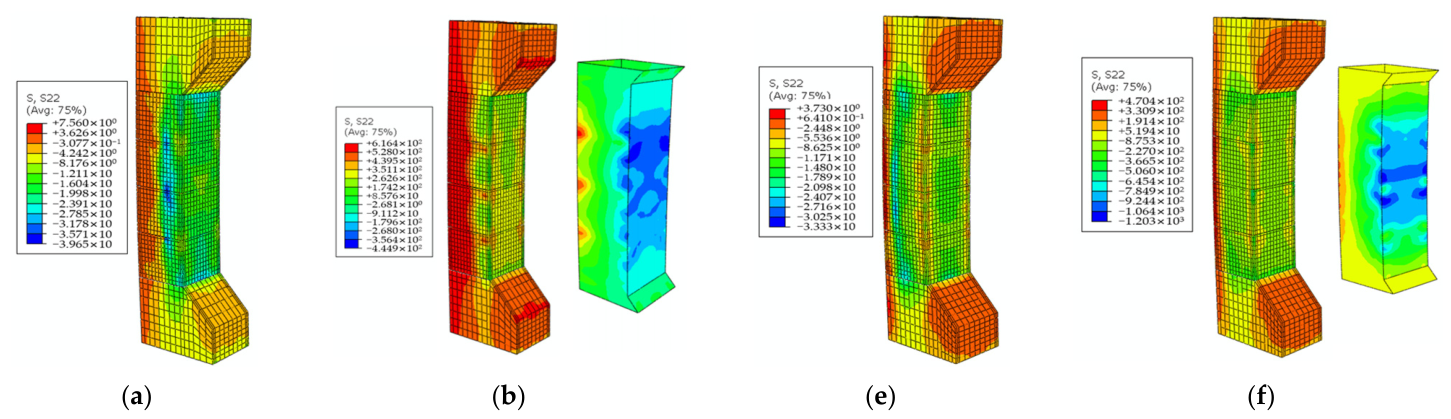
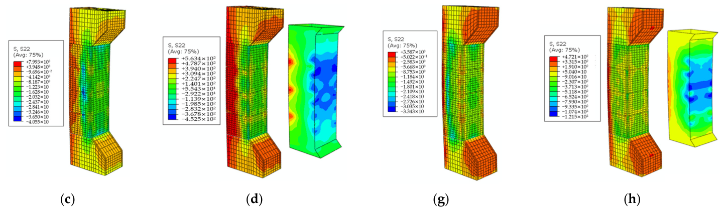
Figure 23a shows the failure mode of the unreinforced column. Under no load, the initial stress state is 0. When the specimen reaches the ultimate bearing capacity, the concrete stress in the compressive zone of the column is 17.65 MPa, the concentrated stress at the corner of the fabricated formwork concrete is 5.37 MPa, and the concrete compressive damage variable is 0.96%. Figure 23b shows the failure mode of the CFRP sheet-strengthened damaged column with an initial stress state of 11.75 MPa and the column under a load of 503.30 kN. When the specimen reaches the ultimate bearing capacity, the concrete compressive damage variable is 0.96%. Although the stress on the concrete increases, the stress distribution at the corner of the fabricated panel decreases. This indicates that after CFRP sheet strengthening, with a continuous increase in load, crack propagation is delayed compared with the unreinforced column; the height of concrete in the compressive zone increases, and the compressive stress distribution becomes more uniform.
Figure 23.
Failure mode analysis process of damaged fabricated columns strengthened with CFRP sheets. (a) Unreinforced column. (b) CFRP sheet-strengthened damaged column.
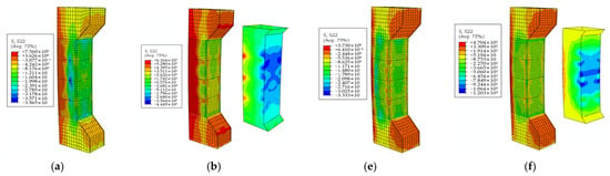
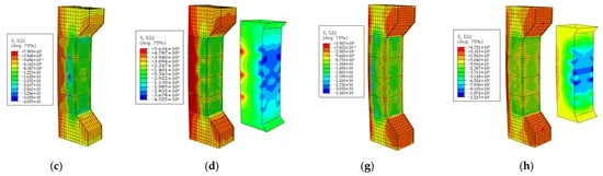
Figure 24 shows the axial stress nephograms of concrete in unreinforced and strengthened concrete eccentric compression columns at ultimate bearing capacity. For small eccentric compression specimens strengthened with full wrapping CFRP sheets, the axial compressive stress value under ultimate bearing capacity of concrete is increased, the height of the compressive zone is also increased, and the distribution of compressive stress is more uniform. The compressive stress gradually decreases from the compressive zone to the tensile zone of the column, and the fabricated formwork concrete is mainly affected by tensile stress. For large eccentric compression specimens under full wrapping strengthening, the axial compressive stress of concrete does not change significantly, and the height of the compressive zone does not change obviously. It can be seen from the stress nephograms of CFRP sheets of specimens D3-1 and D6-1 that the greater the damage degree, the stronger the confinement effect of CFRP sheets on concrete, and the more uniform the distribution of concrete compressive stress. It can be seen from the stress nephograms of CFRP sheets of specimens D3-2 and D6-2 that under large eccentric compression state, the greater the damage degree, the smaller the confinement effect of CFRP sheets on concrete in the tensile zone.
Figure 24.
Axial stress nephograms of concrete under ultimate bearing capacity of unreinforced and reinforced damaged specimens. (a) D3-1. (b) D3-1. (c) D6-1. (d) D6-1. (e) D3-2. (f) D3-2. (g) D6-2. (h) D6-2.
6. Conclusions
This paper employs ABAQUS finite element software to construct finite element models of cast-in-place columns, fabricated columns, and CFRP sheet-confined fabricated columns. On this basis, the effects of column damage degree, concrete strength grade, number of CFRP sheet layers, strip width, and net spacing on the compressive performance of fabricated reinforced concrete columns are analyzed.
- The bearing capacity variation trend of the finite element model is basically consistent with that of the test specimens, and the ultimate bearing capacity error is within 3%, which verifies the correctness of the ABAQUS finite element model and the rationality of the material constitutive relationship established in this paper.
- As the number of CFRP sheet layers increases, both the ultimate bearing capacity and ductility of large and small eccentric compression specimens can be enhanced under full wrapping or strip confinement. The improvement amplitude of ultimate bearing capacity under full wrapping confinement is larger than that under strip confinement. The maximum increase in ultimate bearing capacity can reach 19.18%. For less than three layers of CFRP sheets, the ultimate bearing capacity improvement is relatively significant. The maximum relative improvement can reach 4.84%. When four layers of CFRP sheets are used to confine eccentric compression columns, the improvement amplitude of ultimate bearing capacity is low, the utilization rate of CFRP sheets is small, and the ultimate bearing capacity of axially compressed columns cannot be significantly improved. The maximum relative improvement is merely 1.54%. This indicates that the confinement effect of the members does not increase linearly with the number of layers, and the relative improvement rate will gradually decrease. There is an optimal number of layers for the CFRP sheet strengthening scheme. Based on the simulation results, it is recommended to use 2–3 layers as the ideal number of CFRP sheet layers.
- For constant strip width, a smaller spacing results in smaller concrete strain in the compressive zone. Under the same net spacing, reducing the strip width leads to an increase in the number of cracks in the member while the crack width decreases, and the ultimate bearing capacity of the column diminishes as the strip width decreases.
- After strengthening with CFRP sheets, the ultimate bearing capacity of initially damaged large and small eccentric compression columns is increased, and the deformation capacity and ductility of the members are improved to a certain extent. The damage degree has a greater impact on the ultimate bearing capacity of CFRP sheet-strengthened small eccentric compression columns; the greater the damage degree, the smaller the improvement amplitude in ultimate bearing capacity. The maximum increase in ultimate bearing capacity can reach 8.31%. The damage degree has no significant impact on the ultimate bearing capacity of CFRP sheet-strengthened large eccentric compression columns—regardless of greater damage degree, there is no significant change in the improvement of ultimate bearing capacity.
Author Contributions
Conceptualization, J.W. and W.D.; methodology, C.W.; software, S.Z.; validation, H.Y. and C.W.; formal analysis, S.Z.; investigation, Y.L.; resources, J.W.; data curation, Y.L.; writing—original draft preparation, C.W.; writing—review and editing, J.W.; visualization, W.D.; supervision, J.W.; project administration, J.W.; funding acquisition, J.W. All authors have read and agreed to the published version of the manuscript.
Funding
This research was funded by Shaanxi Provincial Department of Education Government-Enterprise Joint Funding Project (22JE017) and the Scientific Research Foundation for High-level Talents (XJ17T08).
Data Availability Statement
The original contributions presented in this study are included in the article. Further inquiries can be directed to the corresponding author.
Acknowledgments
The authors would like to thank the Shaanxi Key Laboratory of Safety and Durability of Concrete Structures for the project testing.
Conflicts of Interest
The authors declare no conflicts of interest.
References
- Dong, L.R.; Dong, L.R. Research on the Development of Green Building Industry in China. IOP Conf. Ser. Earth Environ. Sci. 2020, 525, 012117. [Google Scholar] [CrossRef] [Scilit]
- Mander, J.B.; Priestley, M.J.N.; Fellow, R.P. Theoretical stress-strain model for confined concrete. J. Struct. Eng. 1988, 114, 1804–1826. [Google Scholar] [CrossRef] [Scilit]
- Yan, S. Research on Environmental Pollution regulation in China’s Construction Industry. J. Archit. Res. Dev. 2021, 5, 33–38. [Google Scholar] [CrossRef] [Scilit]
- Mlayng, A.; Mgonja, C. A Study on the Sustainable Solution for the Construction Industry: Mitigating Air, Water, Soil, and Noise Pollution through Pre-Engineered Structures. J. Prog. Civ. Eng. 2026, 8, 28–34. [Google Scholar]
- Yooprasertchai, E.; Srisuwan, T.; Chotesuwan, A.; Wiwatrojanagul, P.; Suthasit, M.; Pimanmas, A. An investigation of intermediate moment frames constructed using precast concrete for seismic resistance in Thailand. J. Build. Eng. 2026, 120, 115424. [Google Scholar] [CrossRef] [Scilit]
- Sayed, R.; Patil, S.; Sudarsan, J.S. Reducing carbon emissions in prefabricated buildings: A systematic review of LCA-based strategies. Discov. Civ. Eng. 2026, 3, 69. [Google Scholar] [CrossRef] [Scilit]
- Cao, J.; Wang, D.; Han, Z.; Hu, C. Multi-index evaluation on reinforcement programs for frame structures based on life cycle theory and time-varying reliability. J. Build. Eng. 2024, 96, 110520. [Google Scholar] [CrossRef] [Scilit]
- Guan, D.; Xu, R.; Yang, S.; Chen, Z.; Guo, Z. Development and seismic behavior of a novel UHPC-shell strengthened prefabricated concrete column. J. Build. Eng. 2022, 46, 103672. [Google Scholar] [CrossRef] [Scilit]
- Yang, Y.; Xue, Y.; Yu, Y.; Gao, F. Experimental study on seismic performance of partially precast steel reinforced concrete columns. Eng. Struct. 2018, 175, 63–75. [Google Scholar] [CrossRef] [Scilit]
- Stamatopoulos, G.N.; Ermopoulos, J.C. Experimental and analytical investigation of steel column bases. J. Constr. Steel Res. 2011, 67, 1341–1357. [Google Scholar] [CrossRef] [Scilit]
- Kanvinde, A.M.; Grilli, D.A.; Zareian, F. Rotational Stiffness of Exposed Column Base Connections: Experiments and Analytical Models. J. Struct. Eng. 2012, 138, 549–560. [Google Scholar] [CrossRef] [Scilit]
- Chiewanichakorn, M.; Aref, A.J. Finite element simulations of seismic response of precast concrete segmental columns. In Structures Congress 2006: Structural Engineering and Public Safety; American Society of Civil Engineers: Reston, VA, USA, 2006; pp. 1–9. [Google Scholar]
- Xiao, S.; Fomin, N.I.; Khvostunkov, K.A.; Liu, C. Finite Element Analysis of the Influence of End Grouting Defects in Grouted Sleeve on the Structural Performance of Precast Reinforced Concrete Columns. CMES-Comput. Model. Eng. Sci. 2025, 145, 2821–2847. [Google Scholar] [CrossRef] [Scilit]
- Chen, Q.J.; Lei, J.; Wang, Y.T.; Liu, X.; Gao, W.; Yao, M.J.; Cai, J. Dynamic performance of precast concrete columns with pressed sleeve connections under horizontal impact loads. Eng. Struct. 2026, 346, 121707. [Google Scholar] [CrossRef] [Scilit]
- John, S.K.; Cascardi, A.; Verre, S.; Nadir, Y. RC-columns subjected to lateral cyclic force with different FRCM-strengthening schemes: Experimental and numerical investigation. Bull. Earthq. Eng. 2025, 23, 1561–1590. [Google Scholar] [CrossRef] [Scilit]
- Kodur, V.K.R.; Naser, M.Z.; Kim, H.S. Fire performance of concrete structures incorporating FRP reinforcement: State-of-the-art and knowledge gaps. Cem. Concr. Comp. 2025, 161, 106074. [Google Scholar] [CrossRef] [Scilit]
- Wang, J.; Lu, S.; Yang, J. Behavior of eccentrically loaded rectangular RC columns wrapped with CFRP jackets under different preloading levels. J. Build. Eng. 2020, 34, 101943. [Google Scholar]
- Micelli, F.; Cascardi, A.; Aiello, M.A. Pre-load effect on CFRP-confinement of concrete columns: Experimental and theoretical study. Crystals 2021, 11, 177. [Google Scholar] [CrossRef] [Scilit]
- Nematzadeh, M.; Mousavimehr, M.; Shayanfar, J.; Omidalizadeh, M. Eccentric compressive behavior of steel fiber-reinforced RC columns strengthened with CFRP wraps: Experimental investigation and analytical modeling. Eng. Struct. 2021, 226, 111389. [Google Scholar] [CrossRef] [Scilit]
- Salman, F.T.; Hassoun, E.O.; Ahmed, M.K. Fatigue Behavior under Constant Load of CFRP Sheets Compared to Their Performance under Static Load. J. Compos. Adv. Mater. 2025, 35, 143. [Google Scholar] [CrossRef] [Scilit]
- Mirmiran, A.; Shahawy, M.; Samaan, M.; Echary, H.E.; Mastrapa, J.C.; Pico, O. Effect of column parameters on FRP-confined concrete. J. Compos. Constr. 1998, 2, 175–185. [Google Scholar] [CrossRef] [Scilit]
- Ilki, A.; Kumbasar, N. Behavior of damaged and undamaged concrete strengthened by carbon fiber composite sheets. Struct. Eng. Mech. 2002, 13, 75–90. [Google Scholar] [CrossRef] [Scilit]
- Ilki, A.; Kumbasar, N.; Koc, V. Low strength concrete members externally confined with FRP sheets. Struct. Eng. Mech. 2004, 18, 167–194. [Google Scholar] [CrossRef] [Scilit]
- Ilki, A.; Kumbasar, N. Compressive behaviour of carbon fibre composite jacketed concrete with circular and non-circular cross-sections. J. Earthq. Eng. 2003, 7, 381–406. [Google Scholar] [CrossRef] [Scilit]
- Maaddawy, T.E. Strengthening of eccentrically loaded reinforced concrete columns with fiber-reinforced polymer wrapping system: Experimental investigation and analytical modeling. J. Compos. Constr. 2009, 13, 13–24. [Google Scholar] [CrossRef] [Scilit]
- Abbasnia, R.; Ziaadiny, H. Experimental investigation and strength modeling of CFRP-confined concrete rectangular prisms under axial monotonic compression. Mater. Struct. 2015, 48, 485–500. [Google Scholar]
- Thomas, J.; Ramadass, S. Improved empirical model for the strut efficiency factor and the stiffness degradation coefficient for the strength and the deflection prediction of FRP RC deep beams. Structures 2021, 29, 2044–2066. [Google Scholar] [CrossRef] [Scilit]
- Bakar, M.B.C.; Muhammad Rashid, R.S.; Amran, M.; Saleh Jaafar, M.; Vatin, N.I.; Fediuk, R. Flexural strength of concrete beam reinforced with cfrp bars: A review. Materials 2022, 15, 1144. [Google Scholar] [CrossRef] [Scilit] [PubMed]
- Ding, Z.; Wen, J.; Li, X.; Fu, J.; Ji, X. Mechanical behaviour of polyvinyl alcohol-engineered cementitious composites (PVA-ECC) tunnel linings subjected to vertical load. Tunn. Undergr. Space Technol. 2020, 95, 103151. [Google Scholar] [CrossRef] [Scilit]
- GB/T 50081-2019; Test Methods of Concrete Physical and Mechanical Properties. China Architecture & Building Press: Beijing, China, 2019.
- GB 50010-2010; Code for Design of Concrete Structures. China Architecture & Building Press: Beijing, China, 2010.

Disclaimer/Publisher’s Note: The statements, opinions and data contained in all publications are solely those of the individual author(s) and contributor(s) and not of MDPI and/or the editor(s). MDPI and/or the editor(s) disclaim responsibility for any injury to people or property resulting from any ideas, methods, instructions or products referred to in the content. |
© 2026 by the authors. Licensee MDPI, Basel, Switzerland. This article is an open access article distributed under the terms and conditions of the Creative Commons Attribution (CC BY) license.