


Abstract
Post-weld cold rolling and subsequent annealing were applied to friction-stir-welded Al/Cu joints to examine their interfacial evolution, tensile behavior, and local cupping response. Multi-pass cold rolling reduced the sheet thickness from 3.0 to 0.4 mm and transformed the initially inclined Al/Cu interface into a near-horizontal laminated structure with an average inclination of 3.97° relative to the sheet plane. Rolling fragmented and thinned the interfacial reaction layer (narrow nanoscale reaction-product layer) and increased the average tensile strength from 99 to 370 MPa, whereas the elongation remained low at approximately 0.6%. Annealing at 300 °C for 30 min promoted recovery and recrystallization, reduced the hardness difference across the joint, and increased the elongation to 8.8%, with an average tensile strength of 182 MPa. The macroscopic tensile fracture path changed from the Al/Cu interfacial region (broad transition zone) in the as-welded joint to the laminated region (rolled interfacial region characterized by alternating Al-rich/Cu-rich lamellae) after rolling and annealing. In contrast, interface-centered cupping specimens exhibited a lower load-carrying capacity and cracking along the interfacial region. These results show that post-weld rolling and annealing improve the uniaxial tensile response through interface flattening and microstructural homogenization, while the interfacial region remains susceptible to cracking during combined stretching and bending deformation.
1. Introduction
Aluminum and copper are widely used in electrical transmission, electronics, electric vehicles, and aerospace components because of their complementary properties. Aluminum offers low density and good formability, whereas copper provides high electrical and thermal conductivity [1,2]. Reliable joining of these dissimilar metals is therefore important for manufacturing lightweight conductive components.
Friction stir welding (FSW) is a solid-state joining process that limits bulk melting and can reduce excessive intermetallic compound (IMC) formation in Al/Cu joints. Nevertheless, interfacial reaction layers and locally mixed Al–Cu regions are commonly formed during FSW [3,4,5,6]. Because these reaction products deform less readily than the adjacent Al and Cu matrices, strain incompatibility and local stress concentration can promote premature cracking in the interfacial region.
Previous studies have improved Al/Cu FSW joints through process-parameter optimization [7,8,9,10,11,12,13], ultrasonic assistance [14,15], external cooling [16,17,18], and metallic interlayers [19,20]. These approaches mainly regulate heat generation, material flow, and interfacial reactions during welding. However, the post-weld geometry and deformation compatibility of the interfacial region may also influence the subsequent mechanical response, especially when the joint is subjected to additional forming operations.
Post-weld thermo-mechanical processing provides another route for modifying the microstructure and mechanical response of welded joints [21,22,23,24,25]. It should be noted, however, that thermal treatment alone, particularly when a continuous Al/Cu reaction layer is retained, may be undesirable for Al/Cu joints, as elevated temperatures promote further thickening of the brittle interfacial IMC layer, deteriorating the mechanical properties. Similarly, while surface mechanical treatments (e.g., shot peening or laser peening) can effectively modulate surface residual stresses, they may have limited ability to directly modify the buried Al/Cu interface or mitigate the internal stress concentrations caused by the continuous IMC layer. Consequently, large-strain plastic deformation, such as cold rolling and forging, is more appropriate for this specific system because it can physically fragment and redistribute the brittle interfacial IMC layer, while simultaneously refining the adjacent microstructures. Beygi et al. [26] reported that cold rolling increased the tensile strength of Al/Cu FSW joints but markedly reduced their ductility because of work hardening and fragmentation of the interfacial reaction products. In an earlier study, Deng et al. [27] showed that cold rolling followed by annealing improved the strength–ductility balance of Al/Cu FSW joints by modifying the interfacial morphology, closing welding defects, and reducing the property gradient across the joint. That work, however, mainly evaluated microstructural evolution and uniaxial tensile properties.
Cold rolling also changes the macroscopic inclination relative to the sheet plane of the Al/Cu interface, which may alter the traction components acting on the bonding region during tensile loading. Therefore, the change in tensile fracture location after rolling and annealing may result from the combined effects of microstructural homogenization, reduction in interface inclination, and changes in the interfacial reaction layer. In addition, the response of the processed joint during sheet-forming deformation has received less attention. Erichsen cupping, which combines biaxial stretching with bending and contact loading, provides a practical method for comparing the local cupping responses of the Al side, Cu side, and interfacial region.
In this study, Al/Cu FSW joints were subjected to multi-pass cold rolling and subsequent annealing. The evolution of the macroscopic interface geometry, interfacial reaction layer, adjacent microstructures, and hardness distribution was characterized using optical microscopy, scanning electron microscopy, energy-dispersive spectroscopy, and transmission electron microscopy. Tensile tests and Erichsen cupping tests were then used to evaluate the mechanical response under uniaxial loading and combined stretching–bending deformation, respectively. The aim was to clarify how post-weld cold rolling and annealing affect the interfacial morphology, tensile fracture path, and local cupping response of the Al/Cu joint.
2. Materials and Methods
2.1. Materials, Welding, Rolling, and Annealing
Commercially pure 1060 Al and T2 Cu sheets with a thickness of 3 mm were used as the base materials. The sheets were machined to 300 mm × 150 mm × 3 mm. Their measured chemical compositions and room-temperature tensile properties are listed in Table 1, Table 2 and Table 3. The chemical compositions were determined via inductively coupled plasma optical emission spectrometry (ICP-OES), and the initial temper conditions were O (annealed) for 1060 Al and M (annealed) for T2 Cu. Before welding, the faying surfaces were mechanically ground to remove surface oxides and then cleaned with ethanol.
Table 1.
Chemical composition of 1060 Al (wt.%).
Table 2.
Chemical composition of T2 Cu (wt.%).
Table 3.
Room-temperature tensile properties of the base materials.
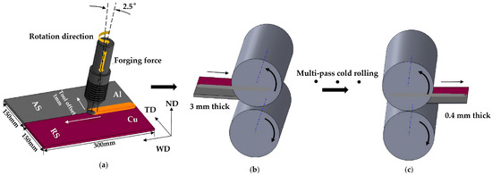
FSW was performed using an MCH2216 (Hunan Kunding CNC Technology Co., Ltd., Changde, China) gantry-type machine at a tool rotation speed of 800 rpm and a welding speed of 30 mm/min. These parameters were selected based on preliminary experimental trials. As illustrated in Figure 1a, the Al sheet was placed on the advancing side (AS) and the Cu sheet on the retreating side (RS). The tool rotated counterclockwise and was offset by 1 mm toward the Al side. The tool consisted of a 13 mm-diameter shoulder and a threaded conical pin with root and tip diameters of 8.0 and 4.0 mm, respectively, and a pin length of 2.85 mm. The tool material, plunge depth, and dwell time were W360 hot work die steel, 0.15 mm, and 5 s, respectively. The tool tilt angle, defined as the angle between the tool axis and the normal to the sheet plane, was −2.5°, where the negative sign indicates backward inclination relative to the welding direction.
Figure 1.
Schematic illustration of the processing route: (a) friction stir welding; (b) first cold-rolling pass; and (c) final cold-rolling pass. WD, welding direction; TD, transverse direction; ND, normal direction.
The as-welded sheets were subsequently cold-rolled along the welding direction (WD), perpendicular to the transverse direction (TD), as shown in Figure 1b,c. The thickness was reduced from 3.0 to 0.4 mm through multiple passes, corresponding to a total thickness reduction of 86.7%. Rolling was performed at room temperature using a laboratory two-high mill (Guangdong Hanyuan Technology Co., Ltd., Foshan, China) with a roll diameter of 200 mm and a rolling speed of approximately 1.5 m/min. A mineral-oil-based lubricant was applied during all passes, and no intermediate annealing was conducted. The pass-by-pass thickness schedule is provided in Table 4.
Table 4.
Pass-by-pass sheet thickness during cold rolling.
The cold-rolled sheets were annealed in a box-type resistance furnace (Changsha Keyuan Vacuum Technology Co., Ltd., Changsha, China). Temperature screening was conducted at 100, 200, 300, and 400 °C for 30 min, and time screening was performed at 300 °C for 10–60 min. The heating rate was 10 °C/min, and the holding time was measured after the furnace reached the set temperature. The specimens were placed flat on a refractory support, annealed in still air, and air-cooled to room temperature after holding.
2.2. Microstructural Characterization
Metallographic specimens were sectioned perpendicular to the welding direction using wire electrical discharge machining. After mounting, grinding, and polishing, the Al side was etched using Keller’s reagent, whereas the Cu side was etched using a ferric chloride–hydrochloric acid solution. The macrostructure and microstructure were examined using an Axiovert 200 MAT optical microscope (Carl Zeiss, Oberkochen, Germany). The interfacial region was characterized using an S-4800 scanning electron microscope (Hitachi, Tokyo, Japan) equipped with energy-dispersive X-ray spectroscopy. The interface inclination and reaction-layer thickness were measured using ImageJ 1.54 software (National Institutes of Health, Bethesda, MD, USA). Thirty interface-angle measurements were performed, while the thickness measurements (n = 5 per condition) were obtained from continuous reaction-layer segments on one representative cross-sectional specimen. Fragmented or missing regions were excluded rather than assigned zero thickness; therefore, the reported values represent the local apparent thickness of the remaining continuous segments rather than the global mean thickness of the entire interface.
Transmission electron microscopy was performed using a JEOL 2010 microscope (JEOL Ltd., Tokyo, Japan). TEM specimens were prepared as 3 mm discs and ion-milled across the Al/Cu interface using an LBS-2 ion mill at a beam current of 5.0 μA. The incidence angle was 7° during the first two-thirds of the milling time and 4° during the remaining period.
2.3. Mechanical Testing
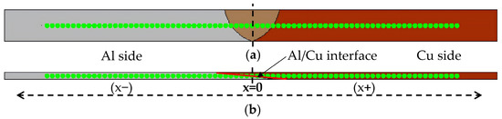
Vickers microhardness was measured along the mid-thickness line of each joint cross-section, as shown in Figure 2. The reference origin (x = 0) was defined differently for the as-welded joint and the post-weld processed conditions. For the as-welded condition, the original Al/Cu interface was designated as the origin. For the cold-rolled and cold-rolled-annealed conditions, the origin was defined as the intersection of the cross-sectional centerline with the Al/Cu interface, corresponding to the physical position of the original weld center. A load of 50 gf (HV0.05), a dwell time of 10 s, and an indentation spacing of 0.5 mm were used. Three hardness profiles were measured for each condition, and the average values were calculated.
Figure 2.
Microhardness measurement paths for (a) the as-welded joint and (b) the cold-rolled and cold-rolled-annealed joints. For the as-welded condition, the original Al/Cu interface was designated as x = 0. For the cold-rolled and cold-rolled-annealed conditions, the reference origin (x = 0) was defined as the intersection of the cross-sectional centerline with the Al/Cu interface, corresponding to the physical position of the original weld center.
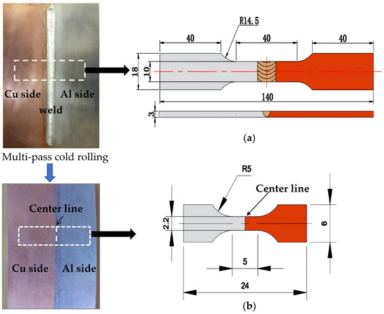
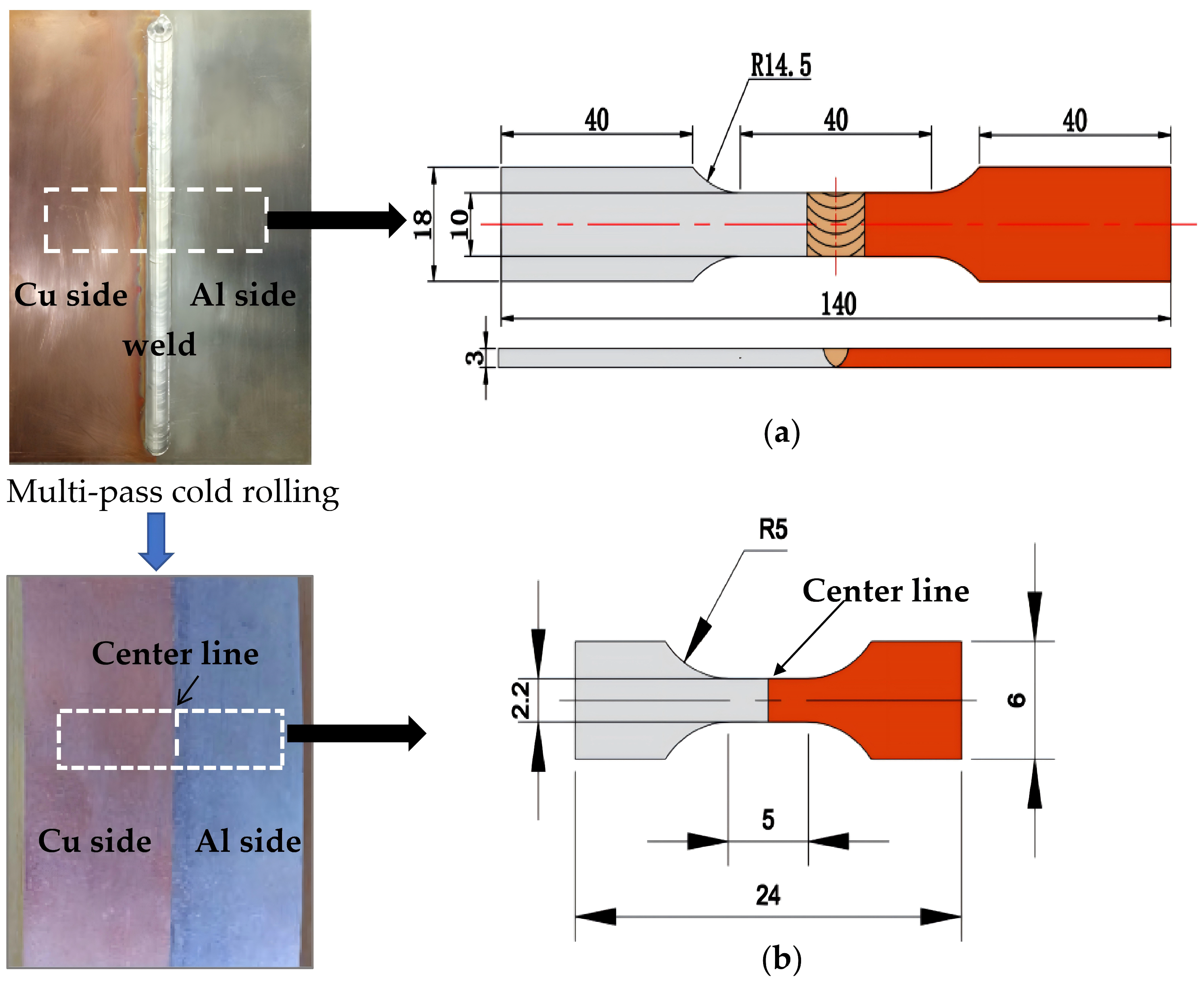
The tensile-specimen sampling positions and dimensions are shown in Figure 3. Room-temperature tensile tests were conducted using an Instron 5848 electromechanical testing machine at an initial strain rate of 1 × 10⁻³ s−1. Strain was measured using a video extensometer. Three specimens were tested for each processing condition, and the results are reported as mean values with standard deviations. The sampling positions followed the recommendations for FSW joints in ISO 25239, whereas the tensile testing procedure followed ISO 6892-1. The tensile loading direction was perpendicular to the welding direction. Both the specimen gauge length and the video-extensometer gauge length were 5 mm.
Figure 3.
Tensile-specimen sampling positions and dimensions for the (a) as-welded and (b) cold-rolled/cold-rolled-annealed joints. All dimensions are in millimeters.
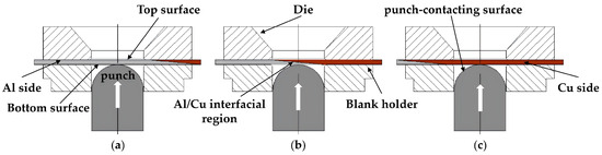
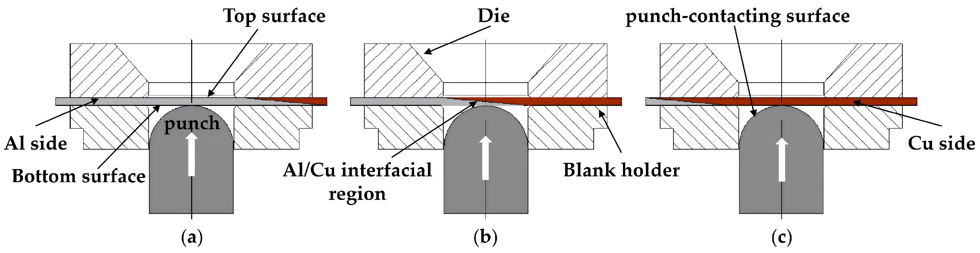
Comparative local cupping tests were conducted with reference to ISO 20482: 2013 [28] to compare the responses of the cold-rolled-annealed sheet at three punch positions, the Al side, the Al/Cu interfacial region, and the Cu side, as illustrated in Figure 4. A spherical punch with a diameter of 20 mm was displaced at 5 mm/min under a blank-holder force of 10 kN. Graphite-based lubricant was applied between the punch and the specimen, and in all local cupping tests, the punch contacted the bottom surface of the sheet, regardless of the lateral test position. Consequently, for tests localized at the Al side, the Al/Cu interfacial region, and the Cu side, the direct friction pairs were punch/Al, punch/Al/Cu interfacial region, and punch/Cu, respectively. Accordingly, the contact material differed among the three test positions; its possible influence on the local deformation response is discussed in Section 3.5.3. Punch force and displacement were continuously recorded until a through-thickness crack was observed. Three specimens were tested at each position.
Figure 4.
Schematic illustration of the positions used for the local cupping tests, with the punch centered on the (a) Al side, (b) Al/Cu interfacial region, and (c) Cu side.
3. Results and Discussion
3.1. Selection of Annealing Condition
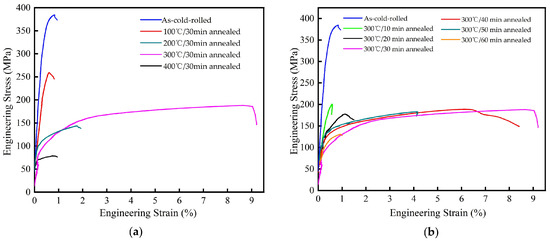
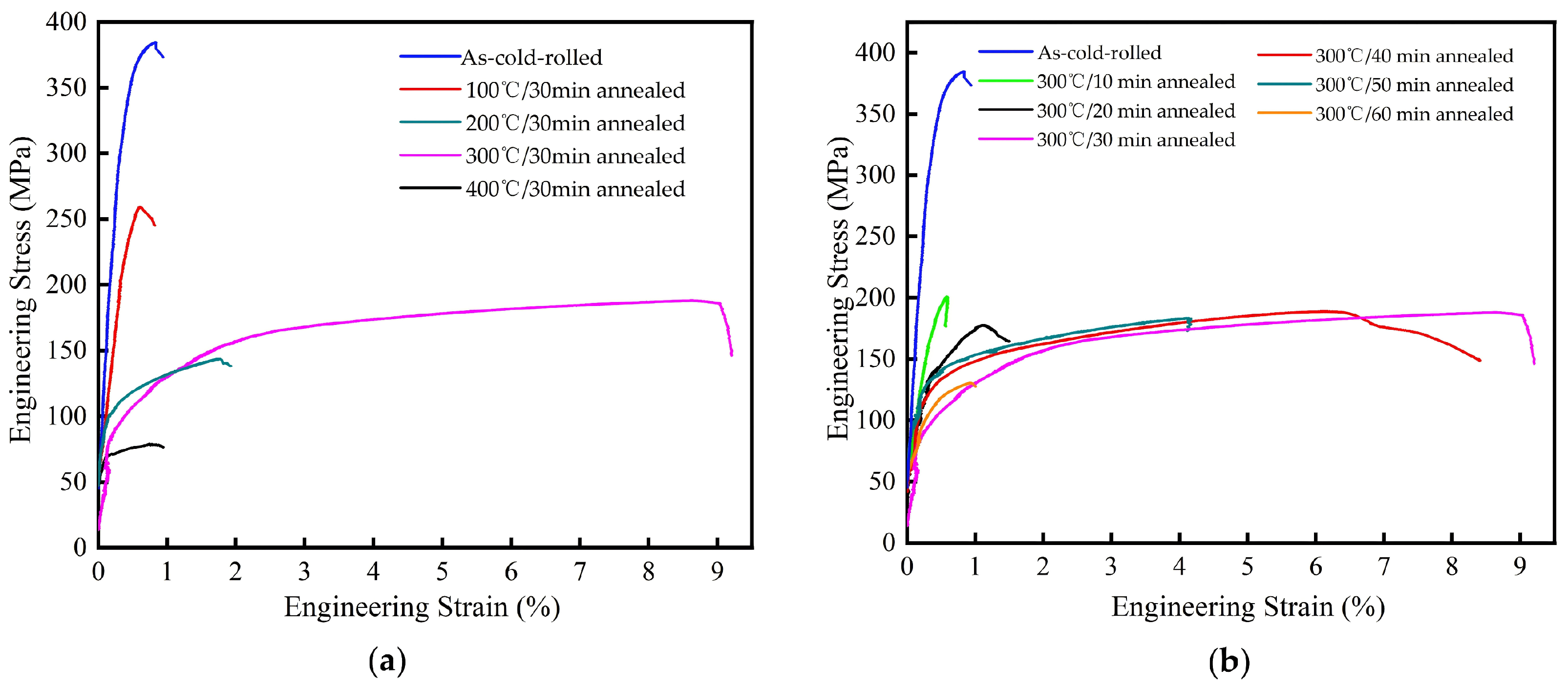
Based on preliminary microstructural and tensile screening, 300 °C for 30 min was selected for detailed characterization. The corresponding screening results are provided in Figure 5. Unless otherwise stated, the term “cold-rolled-annealed” refers to specimens treated at 300 °C for 30 min.
Figure 5.
Tensile stress–strain curves of the post-weld cold-rolled-annealed joints: (a) after annealing at 100, 200, 300, and 400 °C for 30 min; and (b) after annealing at 300 °C for 10–60 min. The as-cold-rolled curve is included in both panels as a reference baseline, and the 300 °C/30 min curve is displayed in both panels to allow direct comparison across the different annealing conditions.
3.2. Microstructural Evolution During Welding, Cold Rolling, and Annealing
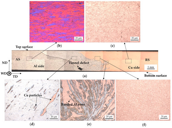
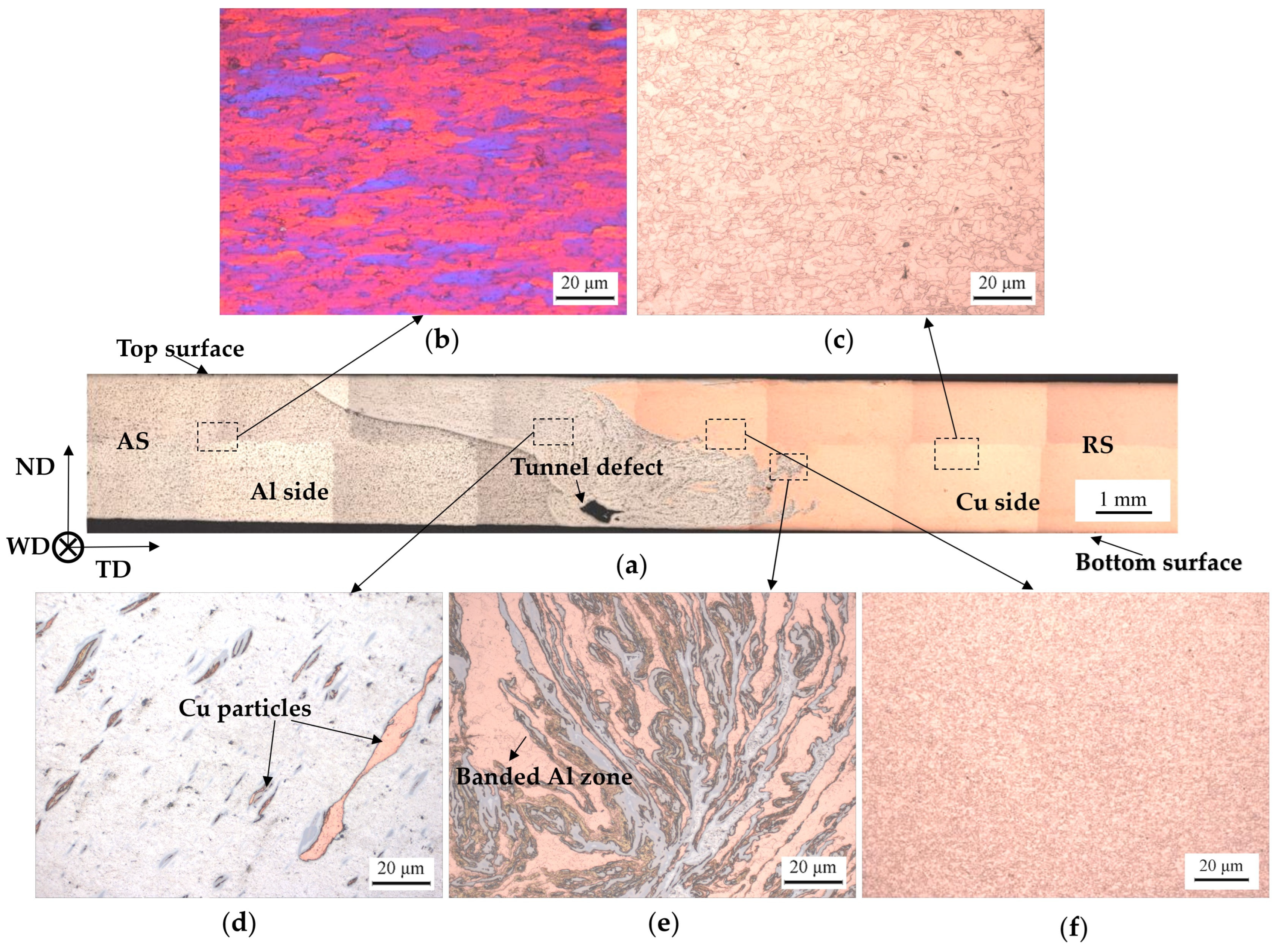
The cross-sectional macrograph of the as-welded joint (Figure 6a) shows an inclined and interlocking Al/Cu morphology. The Al-rich material on the advancing side was transported toward the retreating side, whereas Cu-rich fragments were displaced toward the advancing side by the rotating tool. The upper interfacial region is relatively straight and well defined, while the lower region is more irregular and diffuse. A tunnel-like defect is visible near the weld root, indicating insufficient material consolidation in this local region.
Figure 6.
Optical macrograph and micrographs of the as-welded Al/Cu FSW joint: (a) overall cross-section; (b) Al base metal; (c) Cu base metal; (d) Al-side nugget zone; (e) Al/Cu mixed region; and (f) Cu-side nugget zone.
Figure 6b,c show the base-metal microstructures. The Al base metal exhibits an elongated rolled structure, whereas the Cu base metal contains relatively uniform equiaxed grains. The Al-side nugget zone (Figure 6d) contains dispersed Cu-rich particles produced by tool-induced fragmentation and transport from the Cu side. In the mixed region (Figure 6e), elongated Al-rich and Cu-rich constituents form an interpenetrating, directionally aligned morphology. The Cu-side nugget zone (Figure 6f) contains finer grains than the Cu base metal, consistent with severe plastic deformation and thermally assisted recovery or recrystallization during FSW.
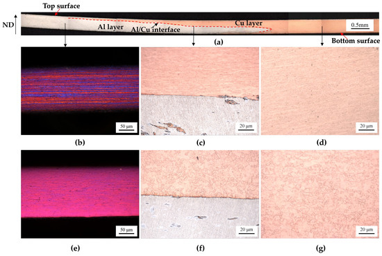
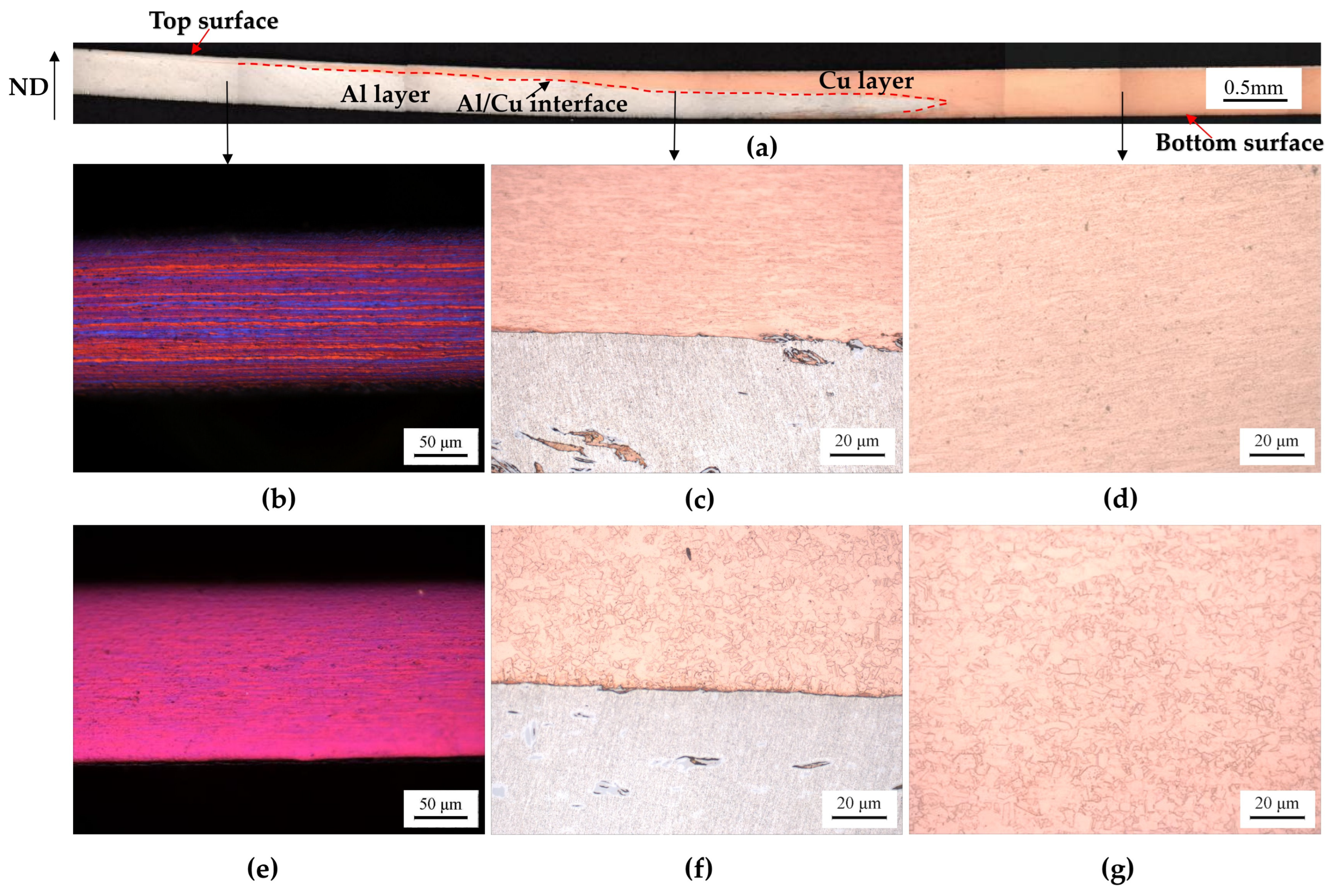
After multi-pass cold rolling, the joint thickness decreased from 3.0 to 0.4 mm. The cross-sectional morphology in Figure 7a shows that the initially inclined and irregular interface was transformed into a near-horizontal laminated structure. ImageJ measurements at 30 positions gave an average interface inclination of 3.97° relative to the sheet plane. The rolled joint can therefore be described as comprising an Al layer, an Al/Cu mixed or reaction region, and a Cu layer arranged through the sheet thickness, with the Al layer being located at the top surface (the upper surface during rolling) and the Cu layer at the bottom surface.
Figure 7.
Cross-sectional and local microstructures after post-weld cold rolling and annealing: (a) overall rolled cross-section; (b) Al side after cold rolling; (c) Al/Cu interfacial region after cold rolling; (d) Cu side after cold rolling; (e) Al side after cold rolling and annealing; (f) Al/Cu interfacial region after cold rolling and annealing; and (g) Cu side after cold rolling and annealing.
The Al side adjacent to the interface exhibits a pronounced banded structure aligned with the rolling direction (Figure 7b). A similar deformation-induced banded morphology is observed on the Cu side (Figure 7d), indicating extensive plastic deformation and grain elongation in both constituents. The macroscopic Al/Cu boundary remains well defined after rolling (Figure 7c). The tunnel-like defect observed in the as-welded cross-section is not visible in the examined rolled section, suggesting geometric closure under compressive deformation; however, this observation alone does not demonstrate complete metallurgical healing of the defect.
After annealing at 300 °C for 30 min, the fibrous morphology on the Al side is partially weakened (Figure 7e), indicating recovery and limited microstructural rearrangement. The macroscopic Al/Cu boundary remains distinct (Figure 7f). On the Cu side, the deformed bands are largely replaced by fine equiaxed grains (Figure 7g), indicating a predominantly recrystallized microstructure. The different responses of the Al and Cu sides are consistent with their different stored energies, stacking-fault energies, and recrystallization kinetics [26,27].
3.3. Evolution of the Interfacial Reaction Layer
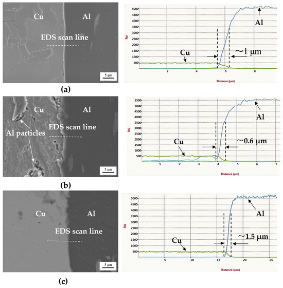
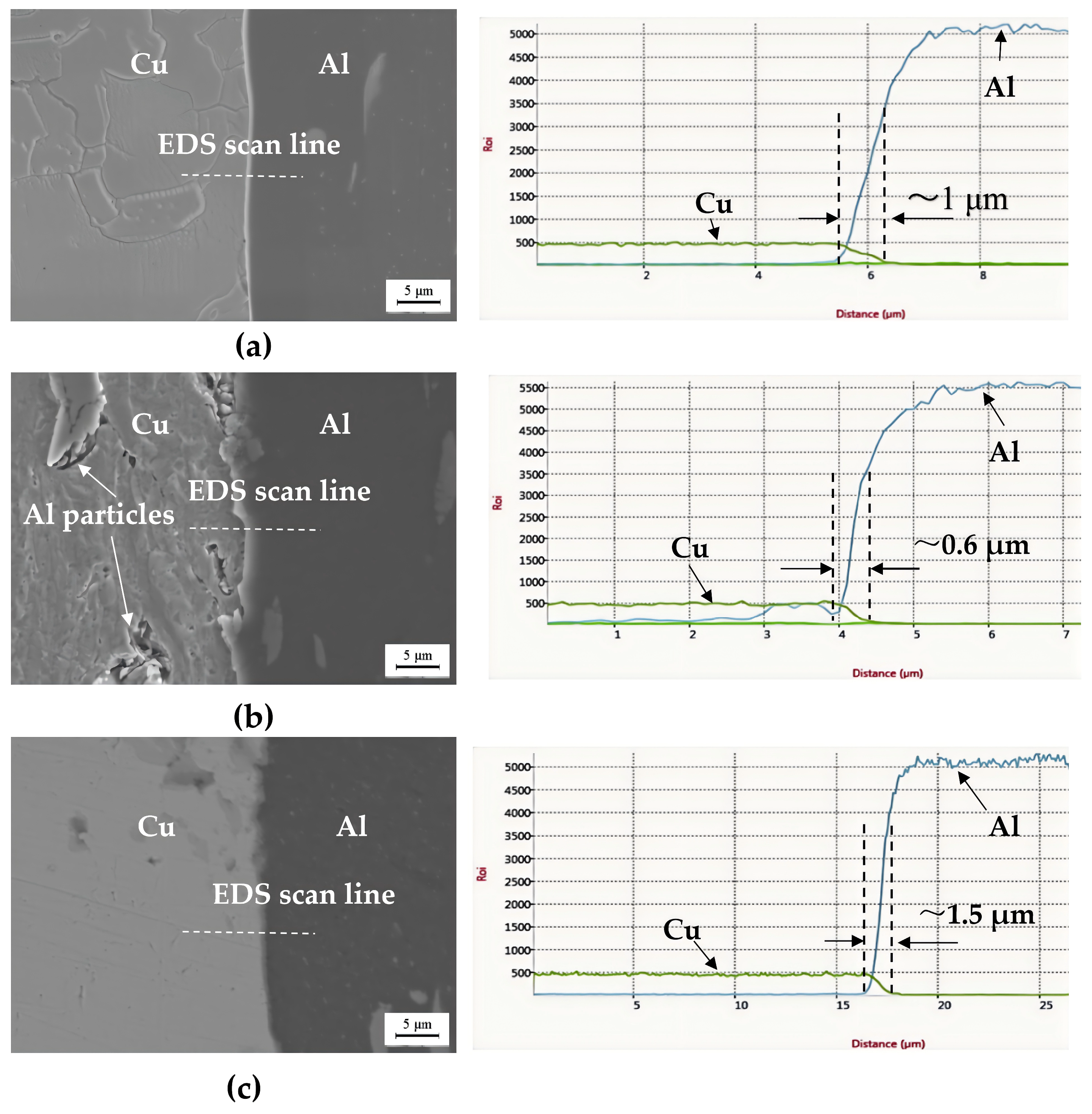
Figure 8 compares the interfacial regions of the as-welded, cold-rolled, and cold-rolled-annealed joints using backscattered-electron imaging and EDS. In the as-welded joint (Figure 8a), a relatively continuous reaction layer with a representative local apparent thickness of the remaining continuous segments of 1.0 ± 0.15 μm (range: 0.8~1.2 μm) is observed. Here, “apparent thickness” refers to the measured distance across the interfacial reaction zone along the EDS scan line, as observed in the 2D cross-section.
Figure 8.
Backscattered-electron images and EDS analyses of the Al/Cu interfacial region in the (a) as-welded, (b) cold-rolled, and (c) cold-rolled-annealed conditions.
After cold rolling (Figure 8b), the layer is locally thinned and fragmented, and microcracks are visible within or adjacent to the interfacial region. These features are consistent with the limited plastic accommodation of the hard reaction products relative to the surrounding Al and Cu matrices. For the statistical measurements, the EDS scan lines were only placed across the macroscopically continuous segments of the layer, while fragmented gaps were excluded from the mean calculations to assess the intrinsic thickness of the remaining IMC. The local apparent thickness of the remaining continuous reaction-layer segments decreases to 0.6 ± 0.14 μm (range: 0.45~0.8 μm) after rolling. Local cracking is also observed around some Al-rich constituents embedded in the Cu-rich region.
After annealing at 300 °C for 30 min (Figure 8c), the interfacial reaction layer appears more continuous than in the cold-rolled condition, and its local apparent thickness increases to 1.5 ± 0.19 μm (range: 1.25~1.75 μm). This evolution is attributed to thermally activated Al–Cu interdiffusion and further interfacial reaction. The reduced number of visible discontinuities suggests partial re-establishment of interfacial continuity; however, the present observations do not demonstrate complete healing of all rolling-induced microcracks. The increased layer thickness also indicates that annealing promotes reaction-layer growth, which may benefit continuity but can retain a brittle interfacial constituent. The fragmentation behavior observed after cold rolling is consistent with the findings of Beygi et al. [26], where the hard IMC layer failed to accommodate the applied compressive strain. Likewise, the increase in the local apparent reaction-layer thickness after annealing agrees with the thermally activated interfacial evolution reported by Deng et al. [27]. Although slight geometric overestimations may arise from minor deviations between the scan line and the true interface normal, such geometric effects are consistent across all conditions and do not alter the observed comparative trends.
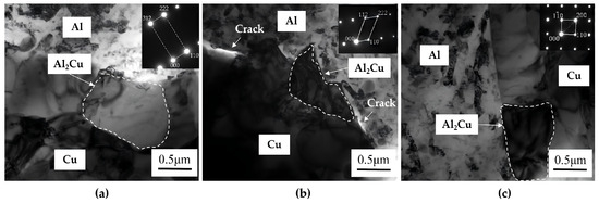
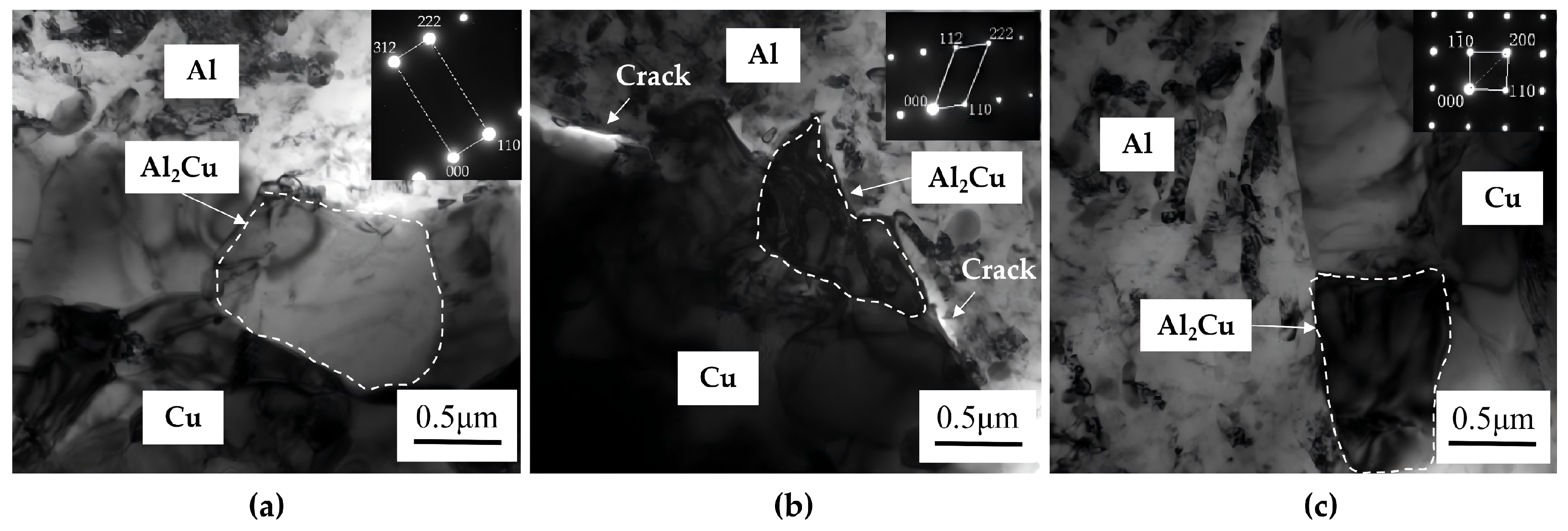
Figure 9 shows TEM images of the Al/Cu interfacial region in the three processing conditions. In the as-welded joint (Figure 9a), a thin and relatively continuous reaction layer is observed between the Al- and Cu-rich regions. Its formation is associated with frictional heating, severe plastic deformation, and short-range interdiffusion during FSW. After cold rolling (Figure 9b), the reaction layer becomes locally discontinuous and contains fragmented regions, consistent with the SEM observations. The limited deformability of the reaction products relative to the adjacent matrices promotes local cracking and separation during the large rolling reduction.
Figure 9.
TEM images of the Al/Cu interfacial region in the (a) as-welded, (b) cold-rolled, and (c) cold-rolled-annealed conditions. The images in panels (a–c) were acquired at the same nominal magnification; the observation areas are representative local regions rather than identical spatial locations.
After annealing (Figure 9c), a more continuous reaction layer is observed locally, indicating further interdiffusion and interfacial reaction during heat treatment. Based on the indexing of selected-area electron diffraction (SAED) patterns (insets in Figure 9) and the TEM/EDS characteristics, the interfacial reaction layer is identified as an Al2Cu-rich phase.
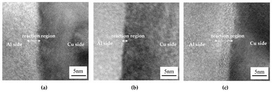
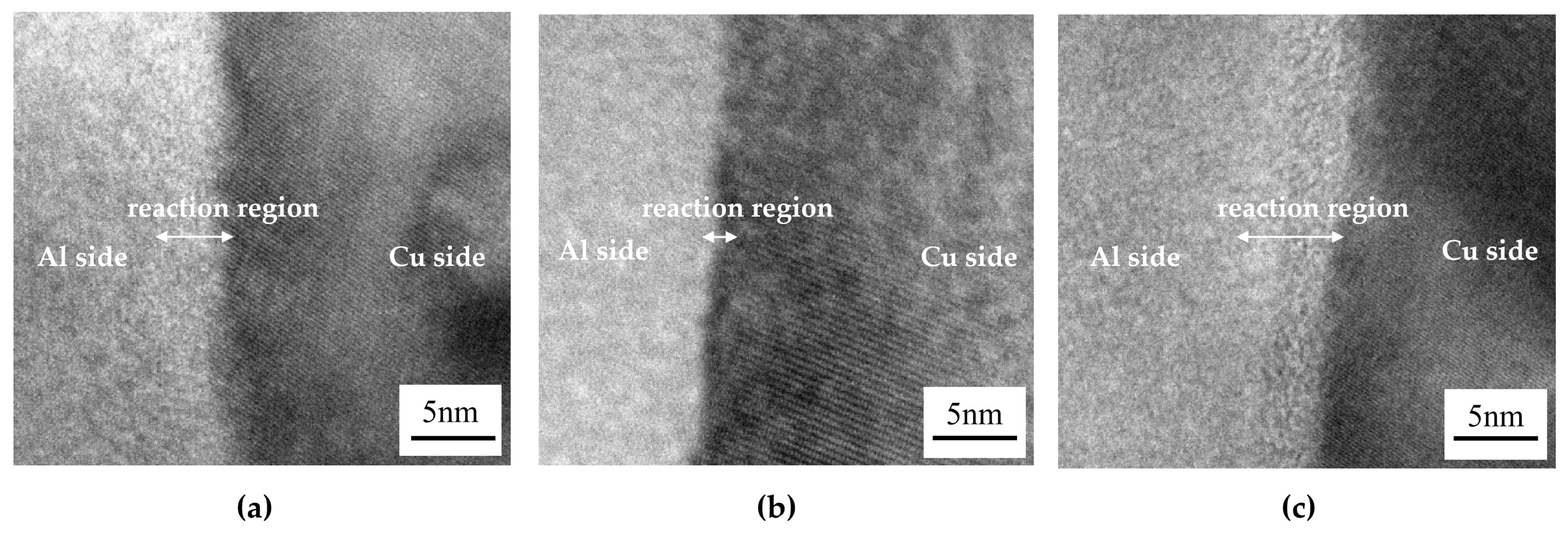
The HRTEM images in Figure 10 provide local evidence of the interfacial evolution. In the as-welded condition (Figure 10a), a nanoscale reaction region with a relatively continuous contrast is observed between the Al- and Cu-rich areas. Local lattice distortion may be associated with the severe deformation and residual strain generated during FSW.
Figure 10.
HRTEM images of the Al/Cu interfacial region in the (a) as-welded, (b) cold-rolled, and (c) cold-rolled-annealed conditions. The images in panels (a–c) were acquired at the same nominal magnification; the observation areas are representative local regions rather than identical spatial locations.
After cold rolling (Figure 10b), the interfacial region shows heterogeneous contrast and locally interrupted lattice fringes. These features are consistent with high defect density, severe lattice distortion, and fragmentation of the reaction layer introduced by cold deformation. The stored deformation energy provides a driving force for recovery, recrystallization, and diffusion during subsequent annealing.
After annealing (Figure 10c), the reaction region exhibits a more uniform contrast and improved local continuity, together with reduced lattice distortion. These changes suggest structural relaxation and further Al/Cu interdiffusion. It is noted that the above interpretations are qualitative descriptions based on visual HRTEM features, as quantitative analyses such as FFT or local strain mapping are not included.
3.4. Microhardness Evolution
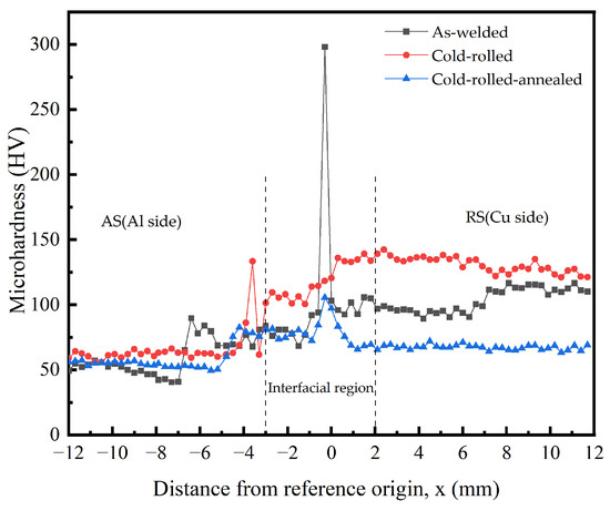
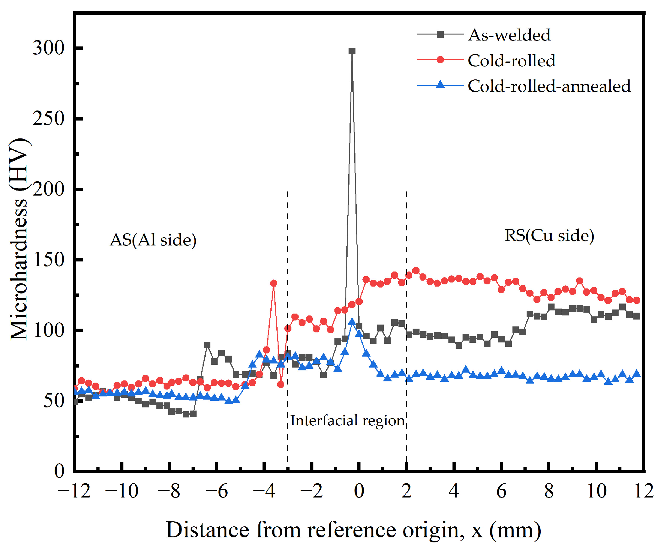
Figure 11 shows the microhardness profiles measured across the joint, in which the negative and positive distances along the horizontal axis correspond to the Al side and Cu side, respectively, and the region around the nominal interface (x = 0) is the interfacial region. The as-welded condition exhibits a pronounced hardness difference between the Al side, mixed region, and Cu side. Locally elevated hardness values in the mixed region may result from the combined contributions of Cu-rich fragments, Al/Cu reaction products, and heterogeneous deformation structures. Because the reaction layer is only approximately 1 μm thick, the HV0.05 indentation cannot isolate its intrinsic hardness. Notably, an isolated peak of approximately 300 HV is recorded exactly at the nominal interface in one of the as-welded hardness measurements. However, this peak was not consistently observed in the corresponding tests under other conditions or in repeated measurements, indicating it was a local abnormality rather than a reproducible feature. The softened regions on the Al and Cu sides are attributed to thermal-cycle-induced recovery and recrystallization of the initially deformed base-metal microstructures.
Figure 11.
Microhardness profiles across the Al/Cu joint in the as-welded, cold-rolled, and cold-rolled-annealed conditions. The horizontal axis represents the distance from the reference origin, x (mm), which is defined separately for the as-welded and post-rolled states in Figure 2.
Cold rolling increases the hardness across most of the joint because of work hardening (Figure 11). The increase is more pronounced on the Cu side than on the Al side, consistent with the lower stacking-fault energy of Cu and its stronger retention of deformation-induced dislocations. The sharp local hardness variation in the original mixed region becomes less pronounced after rolling, which is consistent with the redistribution and fragmentation of Cu-rich constituents and interfacial reaction products.
Annealing at 300 °C for 30 min markedly decreases the hardness on the Cu side. This significant decrease is primarily attributed to the loss of work hardening through recovery and recrystallization. While a fine recrystallized microstructure forms on the Cu side, we note that without quantitative grain-size data, the potential contribution of grain-boundary strengthening cannot be asserted. Thus, the annihilation of deformation-induced dislocations is considered the dominant factor for the observed softening. In contrast, the Al-side hardness changes only slightly after annealing. This difference can be reasonably explained by the distinct stacking-fault energies (SFE) and initial deformation states. Cu with a lower SFE stores a higher dislocation density and greater accumulated energy during cold rolling, providing a strong driving force for recrystallization. Conversely, the higher SFE of Al promotes dynamic recovery; more importantly, the Al side had already undergone significant thermal softening during the prior FSW process, making it less sensitive to the subsequent annealing treatment. The hardness difference across the joint is also reduced after annealing, indicating improved mechanical compatibility between the Al- and Cu-rich regions. After annealing, the difference between the average hardness values measured in the Al-rich and Cu-rich regions decreased to approximately 10 HV. This trend of hardness homogenization after post-rolling annealing is similar to that observed in previous studies [26,27], which attributed such improvements to the relief of deformation incompatibility across the interface. This hardness homogenization, together with recovery and recrystallization, contributes to the improved tensile ductility of the cold-rolled-annealed joint.
3.5. Mechanical Behavior and Fracture Characteristics
3.5.1. Uniaxial Tensile Properties
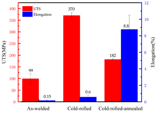
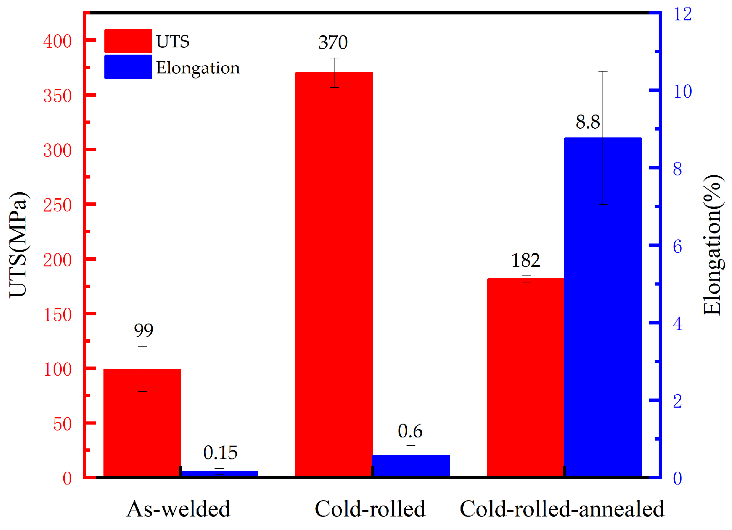
Figure 12 compares the tensile properties of the three processing conditions. The as-welded joint exhibits an average ultimate tensile strength of 99 MPa and an elongation of 0.15%. Cold rolling increases the average tensile strength to 370 MPa through severe work hardening, while the elongation remains limited at approximately 0.6%.
Figure 12.
Ultimate tensile strength and elongation of the Al/Cu joints in the as-welded, cold-rolled, and cold-rolled-annealed conditions. Bars represent mean values, and error bars indicate standard deviations (n = 3).
After annealing at 300 °C for 30 min, the average tensile strength decreases to 182 MPa and the elongation increases to 8.8%. Thus, annealing partially sacrifices the rolling-induced strength while substantially restoring tensile ductility. The plotted values represent the mean ± standard deviation of three specimens.
3.5.2. Tensile Fracture Locations and Fractography
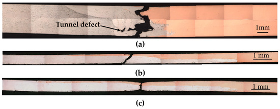
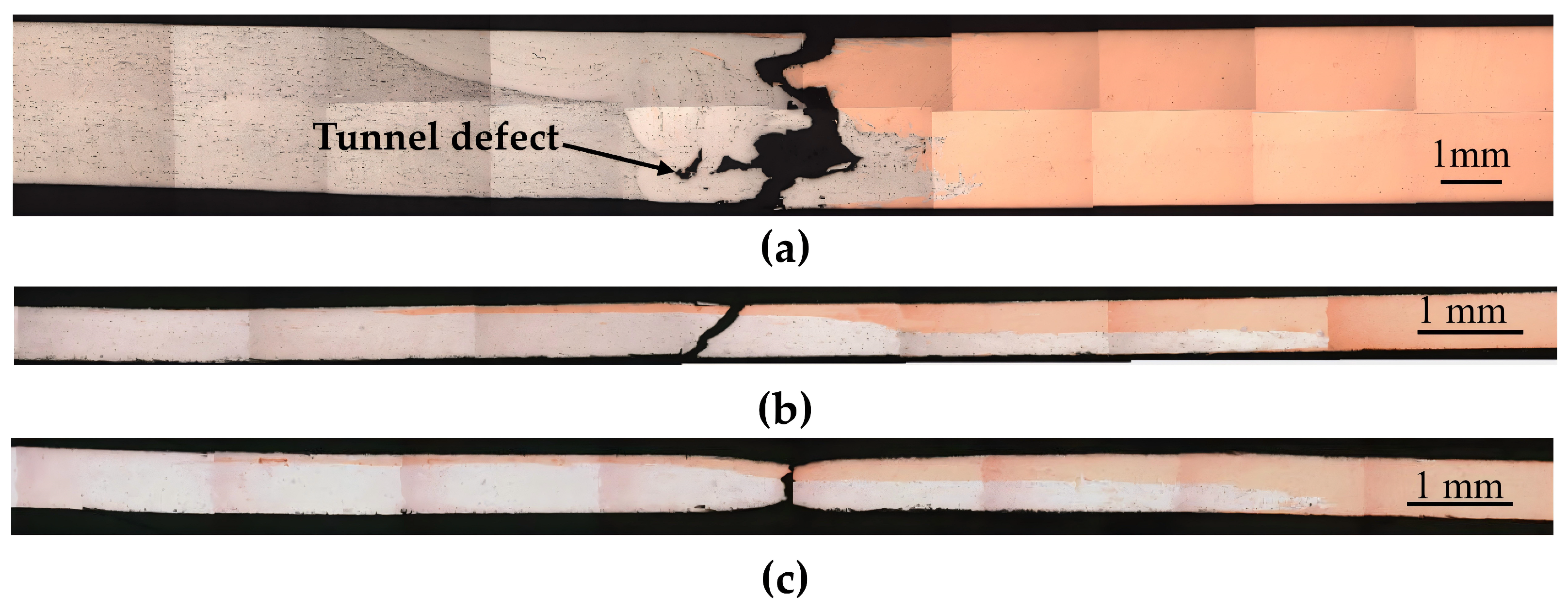
In the examined as-welded specimen, the final tensile fracture path is located in the Al/Cu interfacial region of the nugget zone (Figure 13a) and does not intersect the tunnel-like defect visible in the cross-section. It should be noted that the cross-sectional specimen shown in Figure 6 and the tensile specimen shown in Figure 13 were sampled from adjacent locations along the same weld and are therefore regarded as locally comparable rather than as the exact same physical section. Therefore, based on this specific specimen, the fracture did not intersect the tunnel-like defect; however, this observation does not necessarily imply that the defect does not contribute to fracture under other conditions. The specimen shows no obvious macroscopic necking, consistent with the very low measured elongation.
Figure 13.
Macroscopic tensile fracture locations of the (a) as-welded, (b) cold-rolled, and (c) cold-rolled-annealed joints.
After cold rolling, the macroscopic fracture path passes through the laminated Al/Cu region at an angle of approximately 45° to the tensile axis, and no pronounced necking is observed (Figure 13b). This morphology is consistent with shear-dominated fracture under the highly work-hardened condition. After annealing, the fracture remains within the laminated region, but local necking becomes visible and the fracture plane is nearly perpendicular to the tensile direction (Figure 13c), indicating increased plastic deformation before final failure.
The change in tensile fracture location after rolling and annealing is attributed to several concurrent factors. Cold rolling reorients the macroscopic interface toward the sheet plane and results in geometric closure of the visible tunnel-like defect, while annealing reduces the hardness mismatch and restores plastic deformation in the adjacent matrices. These changes redistribute deformation within the laminated region and reduce the tendency for the original inclined interfacial region to dominate failure under the present uniaxial loading configuration.
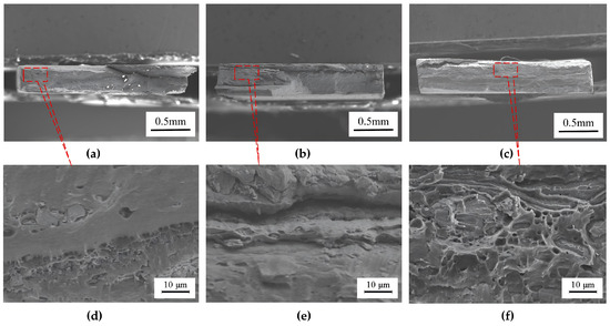
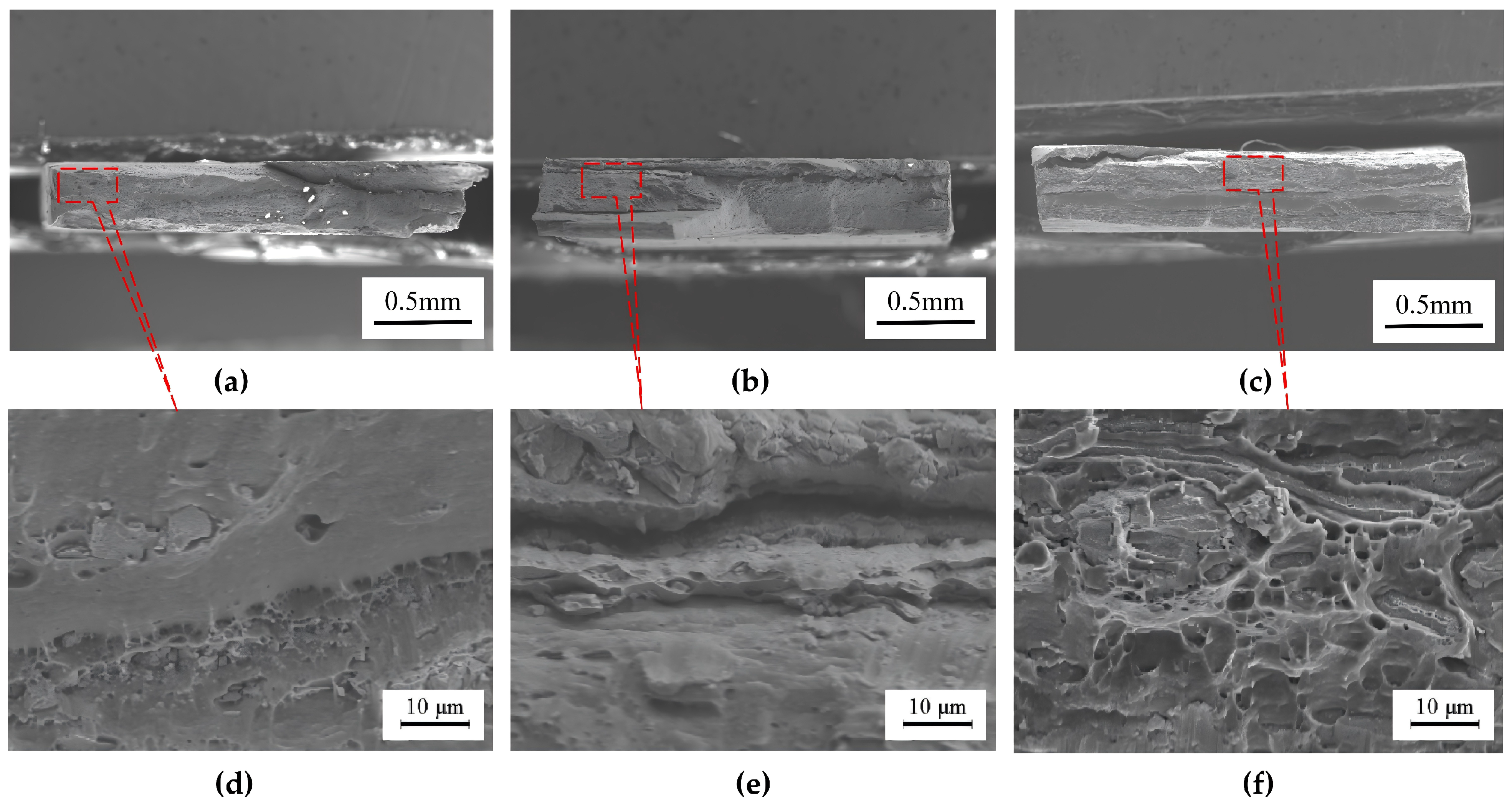
The macroscopic fracture appearances and localized fracture morphologies are shown in Figure 14. The as-welded joint exhibits relatively flat and faceted macroscopic regions with limited evidence of plastic deformation (Figure 14a) which is further confirmed by the localized high-magnification view in Figure 14d. The cold-rolled joint also shows a predominantly flat fracture surface together with shear-related features (Figure 14b), corresponding to the localized morphology in Figure 14e, consistent with its low elongation. In contrast, the cold-rolled-annealed joint contains numerous dimples and tearing features in its localized morphology (Figure 14f), while its macroscopic fracture surface is shown in Figure 14c, indicating a greater contribution from ductile microvoid nucleation and coalescence.
Figure 14.
SEM images of the tensile fracture surfaces. (a–c) Macroscopic low-magnification fractographs of the as-welded, cold-rolled, and cold-rolled-annealed joints, respectively; (d–f) corresponding localized high-magnification SEM images, with the red dashed boxes in (a–c) indicating the specific regions shown in (d–f).
3.5.3. Local Cupping Response of the Cold-Rolled-Annealed Joint
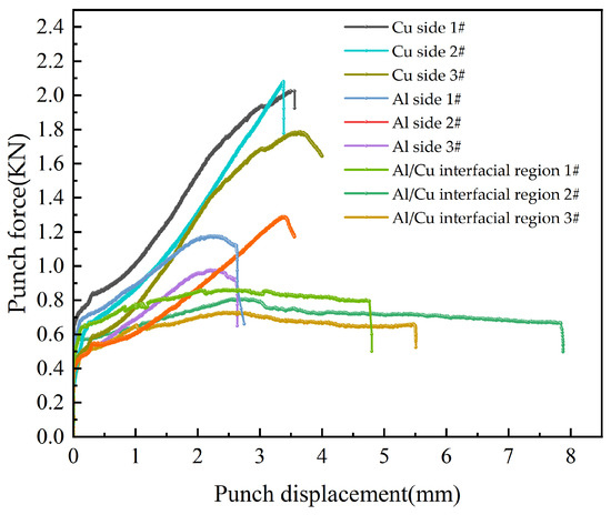
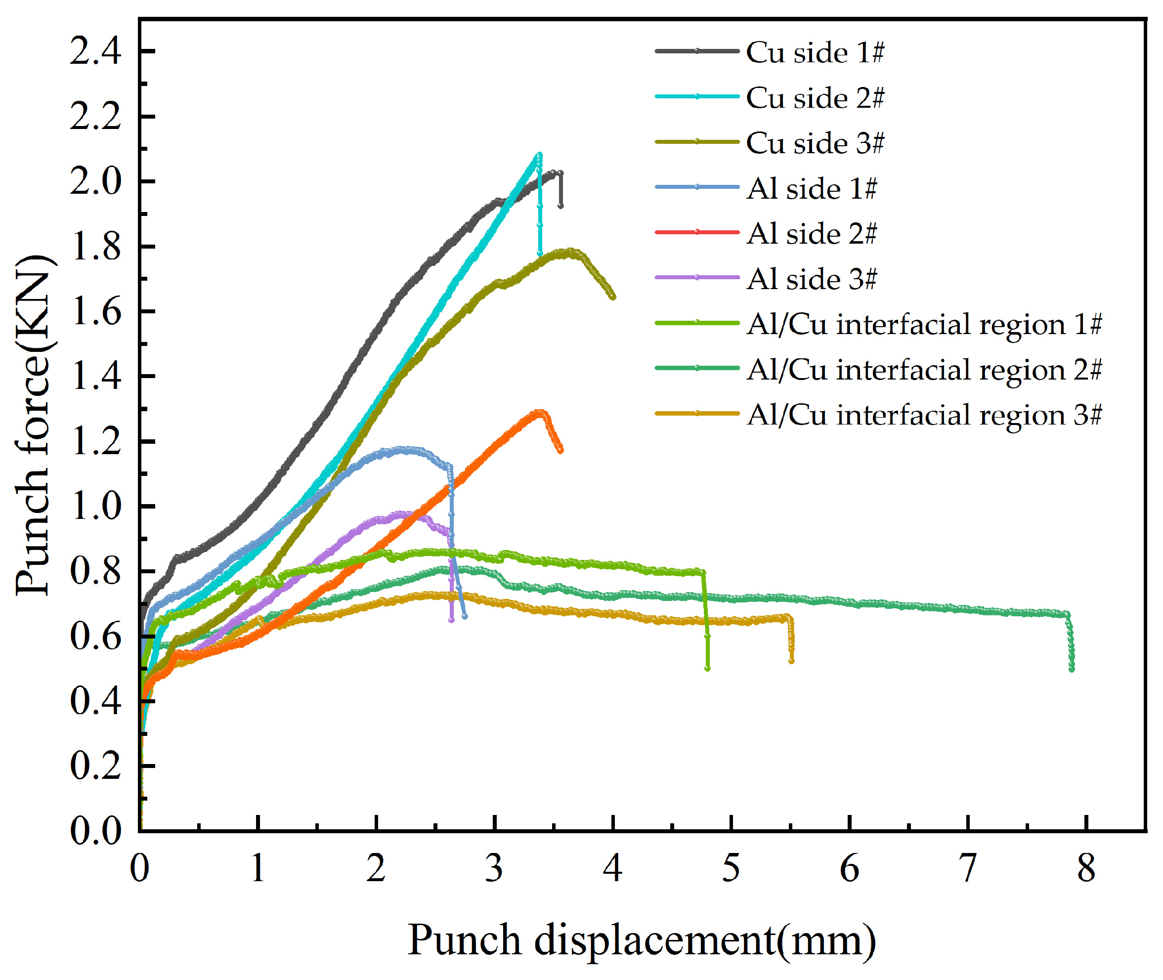
The individual force–displacement curves from three repeated tests are shown in Figure 15. The Cu-side and Al-side specimens exhibited progressive load increases and reached average peak forces of 1.93 ± 0.15 kN and 1.14 ± 0.17 kN (mean ± SD), respectively. In contrast, the interface-centered specimen reached a substantially lower average peak force of 0.78 ± 0.06 kN and subsequently exhibited a plateau followed by load softening. Notably, this specific load plateau and subsequent gradual softening were highly reproducible across all three independent interface tests. This response indicates a lower load-carrying capacity of the interfacial region during combined stretching and bending.
Figure 15.
Individual punch force–displacement curves for local cupping specimens centered on the Al side, Al/Cu interfacial region, and Cu side of the cold-rolled-annealed sheet.
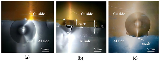
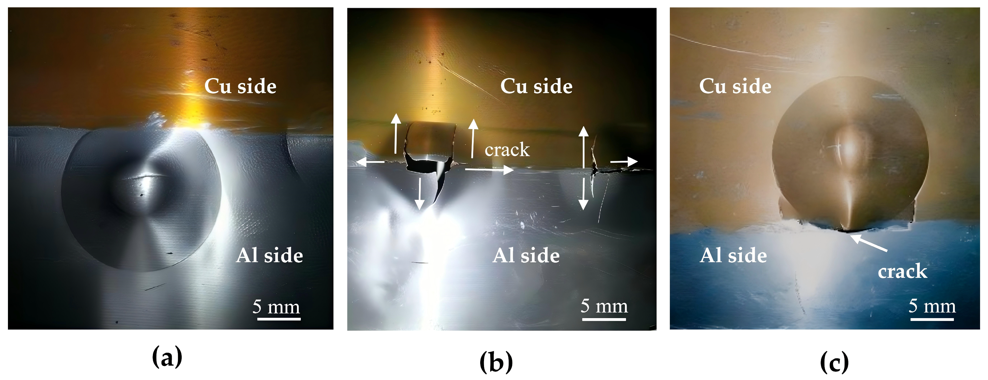
The post-test morphologies in Figure 16 show that the dominant crack in the interface-centered specimen follows the Al/Cu interfacial region. With continued punch displacement, the crack extends along the interface and into the adjacent Al- and Cu-rich regions. These observations demonstrate that the interfacial region remains the preferred fracture path under the present cupping configuration.
Figure 16.
Post-test morphologies and dominant crack paths of the local cupping specimens centered on the (a) Al side, (b) Al/Cu interfacial region, and (c) Cu side.
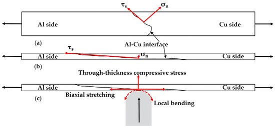
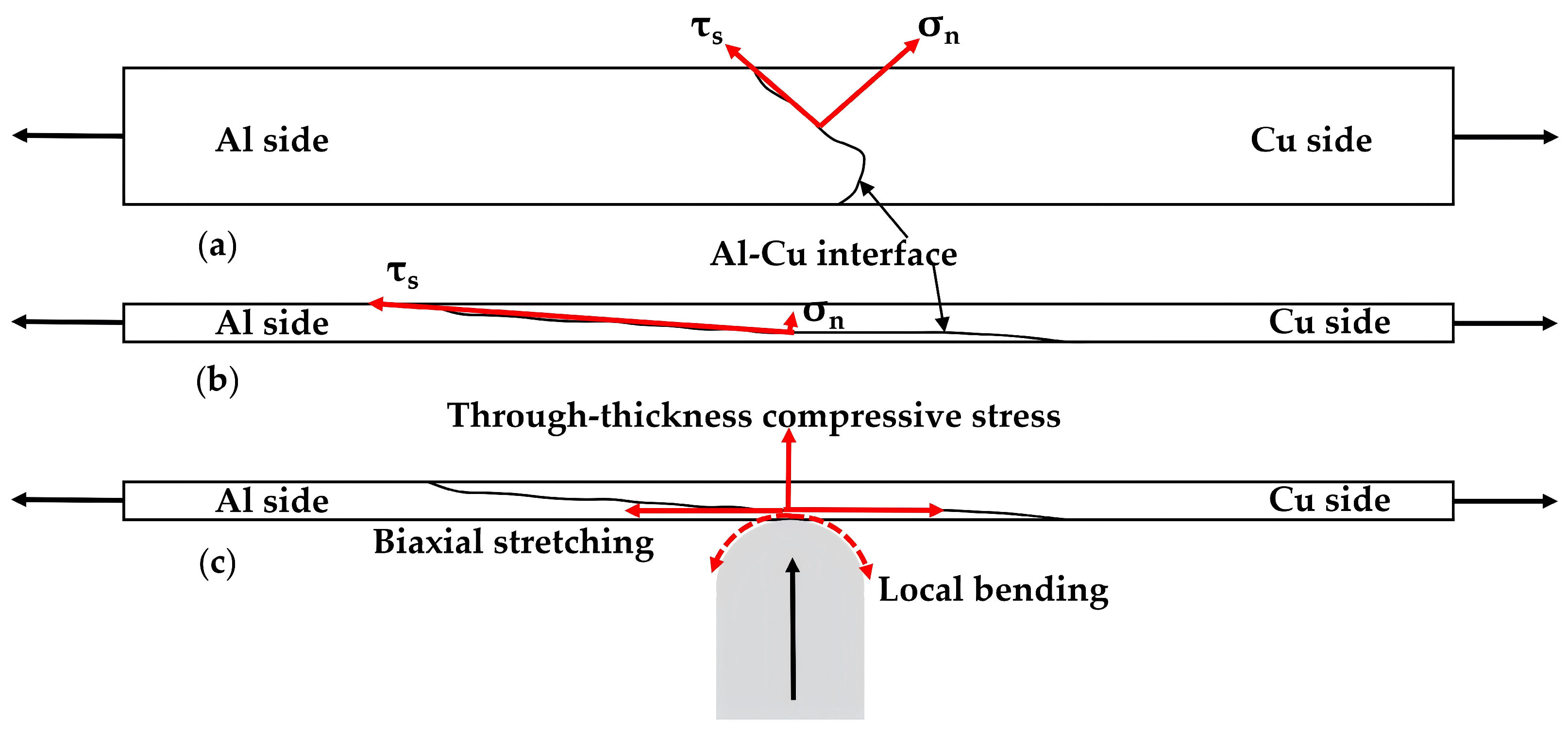
The tensile and cupping results reveal different sensitivities to the interfacial region. As schematically illustrated in Figure 17, under the present uniaxial tensile configuration, the inclined interface induces normal (σn) and shear (τs) stress components (Figure 17a); after cold rolling, the interface is flattened and becomes nearly parallel to the tensile axis, which substantially reduces the normal stress perpendicular to the interface (Figure 17b). This change in interface inclination, combined with geometric defect closure and hardness homogenization, promotes deformation transfer into the laminated region and shifts the final fracture location away from the original inclined interface. During cupping, the sheet experiences biaxial stretching together with bending, contact, and through-thickness stress components (Figure 17c). These combined deformation modes increase the demand for compatibility between the Al matrix, Cu matrix, and the relatively hard interfacial reaction layer. Because the hard reaction layer deforms less readily than the adjacent Al and Cu matrices, local deformation incompatibility can promote stress concentration at the interface. Consequently, the geometric benefit observed in uniaxial tension is insufficient to prevent interface-related cracking during cupping.
Figure 17.
Schematic illustration of the distinct stress states under different loading configurations: (a) as-welded joint with inclined interface decomposed into normal (σn) and shear (τs) stresses under tension; (b,c) cold-rolled-annealed joints exhibiting (b) minimized normal stress on the flattened interface; and (c) complex cupping stresses causing deformation incompatibility.
The results therefore indicate that post-weld rolling and annealing improve the tensile strength–ductility balance but do not eliminate the susceptibility of the interfacial region to cracking during sheet-forming deformation. Such enhancements in tensile properties are essentially driven by the fragmentation of the brittle IMC layer and the recrystallization of the adjacent matrices, which effectively alleviate the interfacial stress concentration. Nevertheless, as demonstrated by Figure 17, the complex multiaxial stress state during cupping exposes a critical trade-off. The hard reaction layer, despite being fragmented, deforms less readily than the ductile Al and Cu matrices and can therefore promote pronounced local stress concentrations, partly offsetting the geometric benefit of interface flattening. Consequently, the improved tensile properties do not fully translate into superior local cupping formability, as the interface remains the preferred failure path under multiaxial loading. These results complement previous studies [27] that primarily focused on the tensile strength–ductility balance, by additionally revealing the inherent limitations of the post-weld thermo-mechanical treatments under complex forming stress states. The remaining limitation is attributed primarily to the deformation incompatibility between the constituent regions and the brittleness of the reaction products, necessitating further innovations such as better IMC growth control, ductile interlayers, or optimized post-processing schedules to fully overcome this bottleneck.
4. Conclusions
(1) Multi-pass cold rolling reduced the joint thickness from 3.0 to 0.4 mm and transformed the initially inclined Al/Cu interface into a near-horizontal laminated structure with an average inclination of 3.97° relative to the sheet plane. The Al2Cu-rich interfacial reaction layer was locally thinned and fragmented during rolling.
(2) Cold rolling increased the average tensile strength from 99 to 370 MPa, but the elongation remained approximately 0.6%. Annealing at 300 °C for 30 min produced a predominantly recrystallized Cu-side microstructure, reduced the hardness mismatch across the joint, and increased the elongation to 8.8%, with an average tensile strength of 182 MPa.
(3) The final tensile fracture location shifted from the Al/Cu interfacial region in the as-welded joint to the laminated region after rolling and annealing. This transition is associated with the reduction in interface inclination, geometric closure of the visible tunnel-like defect, and improved deformation compatibility after annealing.
(4) In the local cupping tests, the interface-centered specimens exhibited a lower load-carrying capacity and earlier load softening than the Al-side and Cu-side specimens, and the dominant crack propagated along the Al/Cu interfacial region. Thus, within the examined specimen geometry and under the present local cupping configuration, the rolling-annealing route improves uniaxial tensile performance but does not eliminate interface-related cracking during combined stretching and bending deformation.
Author Contributions
Conceptualization, Q.D. and X.L.; methodology, Q.D. and F.Y.; investigation, Q.D. and F.Y.; data curation, Q.D.; formal analysis, Q.D. and X.L.; writing—original draft preparation, Q.D.; writing—review and editing, X.L.; visualization, Q.D.; supervision, X.L.; project administration, X.L.; funding acquisition, Q.D. and X.L. All authors have read and agreed to the published version of the manuscript.
Funding
This research was funded by the Natural Science Foundation of Hunan Province, grant number 2024JJ8007; the 2025 Scientific Research Project of the Hunan Provincial Department of Education, grant number 25C1171; and the Excellent Youth Project of the Hunan Provincial Department of Education, grant number 23B0995.
Data Availability Statement
The original contributions of this study are included in the article. For further inquiries, please contact the corresponding author.
Acknowledgments
The authors are grateful to the State Key Laboratory of Metastable Materials Science and Technology, Yanshan University, for their assistance with TEM specimen preparation and mechanical testing.
Conflicts of Interest
Fei You was employed by Zhuzhou CRRC Timly Forge Co., Ltd. The remaining authors declare that the research was conducted in the absence of any commercial or financial relationships that could be construed as a potential conflict of interest.
Abbreviations
The following abbreviations are used in this manuscript:
| FSW | Friction stir welding |
| IMC | Intermetallic compound |
| UTS | Ultimate tensile strength |
| WD | Welding direction |
| TD | Transverse direction |
| ND | Normal direction |
| SEM | Scanning electron microscopy |
| EDS | Energy-dispersive X-ray spectroscopy |
| TEM | Transmission electron microscopy |
| HRTEM | High-resolution transmission electron microscopy |
References
- Payak, V.; Paulraj, J.; Roy, B.S.; Bhargava, M.; Das, P. A review on recent development in aluminium–copper friction stir welding. Proc. Inst. Mech. Eng. Part E J. Process Mech. Eng. 2024, 238, 1462–1506. [Google Scholar] [CrossRef] [Scilit]
- Isa, M.S.M.; Moghadasi, K.; Ariffin, M.A.; Raja, S.; Muhamad, M.R.; Yusof, F.; Jamaludin, M.F.; Yusoff, N.; Ab Karim, M.S. Recent research progress in friction stir welding of aluminium and copper dissimilar joints: A review. J. Mater. Res. Technol. 2021, 15, 2735–2780. [Google Scholar] [CrossRef] [Scilit]
- Mao, Y.; Xiao, X.; Fu, L. Evolution of grain structure, intermetallic compound and mechanical properties of AA6061-T6 Al/C11000 Cu dissimilar joints fabricated by friction stir welding. Sci. Technol. Weld. Join. 2025, 30, 66–77. [Google Scholar] [CrossRef] [Scilit]
- Su, H.; Zhao, Q.; Chen, J.; Wu, C. Homogenizing the intermetallic compounds distribution in Al/Cu dissimilar friction stir welding joint with the assistance of ultrasonic vibration. Mater. Today Commun. 2022, 31, 103643. [Google Scholar] [CrossRef] [Scilit]
- Beygi, R.; Carbas, R.J.C.; Marques, E.A.S.; Barbosa, A.Q.; Kasaei, M.M.; da Silva, L.F.M. Mechanism of toughness enhancement of brittle fracture by intermittent η-intermetallic in Al/Cu joint made by FSW. Mater. Sci. Eng. A 2024, 890, 145907. [Google Scholar] [CrossRef] [Scilit]
- Su, H.; Zhao, Q.; Chen, J.; Wu, C. Evolutions of material flow and intermetallic compounds, and the correlations with mechanical properties of dissimilar Al/Cu friction stir welding joints. J. Mater. Sci. 2022, 57, 20485–20502. [Google Scholar] [CrossRef] [Scilit]
- Su, H.; Chen, J.; Zhao, W.; He, H.; Wu, C. Modeling the effect of plate position on thermal, material flow and deposition during dissimilar friction stir welding between Al and Cu. J. Manuf. Process. 2025, 153, 868–885. [Google Scholar] [CrossRef] [Scilit]
- Wiedenhoft, A.G.; de Amorim, H.J.; Rosendo, T.d.S.; Tier, M.A.D.; Reguly, A. Effect of Heat Input on the Mechanical Behaviour of FSW Lap Joints. Mater. Res. 2018, 21, e20170983. [Google Scholar] [CrossRef] [Scilit]
- Go, B.-S.; Park, D.-M.; Bang, H.-S.; Bang, H.S. Influence of process parameters on joint characteristics in friction stir welding of Al/Cu dissimilar materials for lithium-ion battery. Int. J. Adv. Manuf. Technol. 2024, 130, 1151–1164. [Google Scholar] [CrossRef] [Scilit]
- Xue, P.; Ni, D.R.; Wang, D.; Xiao, B.L.; Ma, Z.Y. Effect of friction stir welding parameters on the microstructure and mechanical properties of the dissimilar Al–Cu joints. Mater. Sci. Eng. A 2011, 528, 4683–4689. [Google Scholar] [CrossRef] [Scilit]
- Nugroho, A.W.; Rahman, K.A.; Rahman, M.B.N. The Effect of Rotational Tool Speed on Dissimilar Joint Aluminum-Copper Plate Friction Stir Welded Joint. Semesta Tek. 2023, 26, 128–136. [Google Scholar] [CrossRef] [Scilit]
- Silvayeh, Z.; Lipińska, M.; Fritsche, S.; Schindler, F.; Auer, P.; Hütter, A.; Marcatto de Oliveira, G.H.; Enzinger, N.; Domitner, J. Microstructural, mechanical and electrical properties of aluminum-copper butt joints produced by high-speed friction stir welding. Mater. Charact. 2025, 224, 114961. [Google Scholar] [CrossRef] [Scilit]
- Hou, W.; Ahmad Shah, L.H.; Huang, G.; Shen, Y.; Gerlich, A. The role of tool offset on the microstructure and mechanical properties of Al/Cu friction stir welded joints. J. Alloys Compd. 2020, 825, 154045. [Google Scholar] [CrossRef] [Scilit]
- You, J.; Zhao, Y.; Dong, C.; Su, Y. Improving the microstructure and mechanical properties of Al-Cu dissimilar joints by ultrasonic dynamic-stationary shoulder friction stir welding. J. Mater. Process. Technol. 2023, 311, 117812. [Google Scholar] [CrossRef] [Scilit]
- Tian, W.; Su, H.; Wu, C. Effect of ultrasonic vibration on thermal and material flow behavior, microstructure and mechanical properties of friction stir welded Al/Cu joints. Int. J. Adv. Manuf. Technol. 2020, 107, 59–71. [Google Scholar] [CrossRef] [Scilit]
- Tang, J.; Shi, L.; Wu, C.; Liu, X.; Zhao, Y. Improving bonding strength of medium-thick Al-Cu dissimilar joint by a novel splat cooling assisted double side friction stir welding. Mater. Charact. 2024, 211, 113878. [Google Scholar] [CrossRef] [Scilit]
- Mao, Y.; Wu, R.; Guo, H.; Xiao, X.; Qin, D.; Fu, L. Improvement in tensile strength of Al/Cu dissimilar joints via submerged friction stir welding: Revealing the action mechanism of water cooling on the intermetallic compound layer. Int. J. Adv. Manuf. Technol. 2023, 128, 2971–2982. [Google Scholar] [CrossRef] [Scilit]
- Yadav, G.; Singh, R.K.R.; Alam, S.; Singh, A. Effect of Process Parameters on the Joint Properties of 6061 Al Alloy-Pure Copper Joints Produced in Under Water FSW. J. Mater. Eng. Perform. 2026, 35, 13161–13174. [Google Scholar] [CrossRef] [Scilit]
- Anbukkarasi, R.; Kailas, S.V. Role of Third Material (Interlayer) on Mechanical Properties of the AA2024-Copper Joints Carried out by Friction Stir Welding (FSW). Trans. Indian Inst. Met. 2019, 72, 1603–1606. [Google Scholar] [CrossRef] [Scilit]
- Sahu, P.K.; Pal, S.; Pal, S.K. Al/Cu Dissimilar Friction Stir Welding with Ni, Ti, and Zn Foil as the Interlayer for Flow Control, Enhancing Mechanical and Metallurgical Properties. Metall. Mater. Trans. A 2017, 48, 3300–3317. [Google Scholar] [CrossRef] [Scilit]
- Ren, Y.; Liu, S.; Hu, X. Effects of pre-weld 6061 base metal composition and post-weld heat treatment on microstructure and mechanical properties of 7075/6061 dissimilar aluminum alloy FSW joints. J. Manuf. Process. 2025, 153, 452–470. [Google Scholar] [CrossRef] [Scilit]
- Du, C.; Pan, Q.; Chen, S.; Tian, S. Effect of rolling on the microstructure and mechanical properties of 6061-T6 DS-FSW plate. Mater. Sci. Eng. A 2020, 772, 138692. [Google Scholar] [CrossRef] [Scilit]
- Chen, J.; Chen, R.; Liao, H.; He, Y.; Chen, P.; Tian, Y.; Zhang, B.; Zhang, Z. Improving joint performance of friction stir welded 2195-O Al-Li alloy by post-weld heat treatment and rolling deformation. J. Mater. Res. Technol. 2024, 29, 5048–5059. [Google Scholar] [CrossRef] [Scilit]
- Song, G.; Wang, Z.; Fan, X.; Liu, L. Research Progress of Aluminum Alloy Welding/Plastic Deformation Composite Forming Technology in Achieving High-Strength Joints. Materials 2023, 16, 7672. [Google Scholar] [CrossRef] [Scilit] [PubMed]
- Panwariya, C.; Kumar Dwivedi, D. Effect of cold rolling on microstructural stability and abnormal grain growth in friction stir welded 7075 aluminum alloy. Mater. Manuf. Process. 2026, 41, 216–228. [Google Scholar] [CrossRef] [Scilit]
- Beygi, R.; Badkoobeh, F.; Sonboli, A.; Ghiasvand, A.; Alirezaei, M.H.; Nouri, A.; Marques, E.A.S.; da Silva, L.F.M. Cold rolling of friction stir welded aluminum/copper joints: Microstructure study, mechanical behavior, and numerical simulation. J. Mater. Eng. Perform. 2025, 34, 29880–29895. [Google Scholar] [CrossRef] [Scilit]
- Deng, Q.; Fu, R.; Jing, L.; Wang, Y. Influence of cold-rolling and annealing treatments on microstructure and mechanical properties of friction stir-welded Al-Cu joints. Sci. Technol. Weld. Join. 2016, 21, 614–623. [Google Scholar] [CrossRef] [Scilit]
- EN ISO 20482:2013; Metallic Materials–Sheet and Strip–Erichsen Cupping Test (ISO 20482:2013); German Version EN ISO 20482:2013. CEN: Brussels, Belgium, 2013.

Disclaimer/Publisher’s Note: The statements, opinions and data contained in all publications are solely those of the individual author(s) and contributor(s) and not of MDPI and/or the editor(s). MDPI and/or the editor(s) disclaim responsibility for any injury to people or property resulting from any ideas, methods, instructions or products referred to in the content. |
© 2026 by the authors. Licensee MDPI, Basel, Switzerland. This article is an open access article distributed under the terms and conditions of the Creative Commons Attribution (CC BY) license.