


Abstract
Smelting with a high scrap ratio in converters holds significant importance for carbon reduction and emission reduction in the iron and steel industry. Under high scrap ratio conditions, the kinetic and thermodynamic conditions of the molten bath change significantly, leading to considerable differences in the elemental reactions and slag formation patterns during the smelting process. To investigate the reaction characteristics and dephosphorization behavior of the molten bath under different scrap ratios, this study conducted thermal simulation experiments of converter smelting with four scrap ratios (20%, 30%, 40%, and 50%) using a 500 kg induction furnace. Scrap preheating and supplemental heating agents were applied as needed. Slag petrographic analysis was carried out using SEM and EDS. The experimental results indicate that with scrap ratios of 20% and 30%, the carbon–oxygen reaction and slag formation efficiency are relatively high. The dephosphorization rate in the early stage of smelting can exceed 50%, and phosphorus is effectively enriched in the CaO–SiO2 matrix phase, with the highest phosphorus distribution ratio observed at a 30% scrap ratio. In contrast, with scrap ratios of 40% and 50%, the carbon–oxygen reaction is slower, and the dephosphorization rate in the early smelting stage is less than 10%. In the 40% scrap ratio experiment, phosphorus began to accumulate significantly in the dicalcium silicate phase during the mid-smelting stage as the basicity increased. At a 50% scrap ratio, the silicate matrix remained the dominant phase throughout all smelting stages, and no distinct phosphorus-rich phase was formed.
1. Introduction
Currently, the long–process converter steelmaking dominates China’s steel industry. Developing application technologies that utilize a large proportion of scrap as ferrous raw material in converters is of great significance for reducing carbon emissions in industry. Metallurgical researchers have conducted extensive studies on jet behavior in the converter bath, slag formation routes, slag–steel interface reactions, and scrap melting. However, research on the application of high scrap ratios, especially above 30%, in conventional combine-blown converters and the laws governing dephosphorization reactions during the smelting process is relatively limited [1]. Under high scrap ratio conditions, issues such as slow lime dissolution, difficulty in slag formation, unstable dephosphorization efficiency, and aggravated lining erosion are not thoroughly described, nor are effective countermeasures proposed.
Through fundamental research on scrap melting behavior during converter smelting, previous studies have established the relationships between scrap melting rate and heat/mass transfer in the liquid bath [2,3,4,5]. Wenyuan Yang [6,7,8,9,10] and others not only described the movement of individual scrap pieces in the bath through cold-state experiments, studied the relationship between scrap addition amount and mixing time, and measured the suspension energy for different scrap sizes, but also characterized the three-stage features of the scrap melting process through thermal simulation tests in a 250 kg induction furnace. Previous research also involved calculating scrap ratios using converter models, studying the impact of factors such as the melting of different scrap types, supplemental coke heating, pig iron usage, and operating practices under high scrap ratio conditions, and proposing control measures to ensure stable production of specific steel grades [11,12]. Some enterprises have studied the melting state of scrap with different ratios and sizes in converters through industrial trials and developed process technologies like secondary combustion, scrap preheating, fuel addition, and bottom-blown powder injection to increase the scrap charge ratio [13,14,15,16]. Besides adding scrap in conventional converters and electric arc furnaces, scrap can also be added in other process stages like blast furnace, hot metal ladle, refining furnace, and tundish to increase overall scrap usage and reduce hot metal consumption [17,18,19,20,21].
Due to the changes in the kinetic and thermodynamic conditions of the molten bath under high scrap ratio conditions, addressing how to achieve efficient decarburization, dephosphorization, and other reactions in the molten bath under such conditions is crucial for producing high-quality molten steel in converter steelmaking. The heat deficit in the bath under high scrap ratios, if compensated by over-blowing at the endpoint, leads to increased total iron in the slag and higher oxygen content in the steel, adversely affecting cost, smooth operation, and steel cleanliness [22]. The melting of scrap during the converter steelmaking process not only causes fluctuations in bath temperature and composition, but also has a significant impact on the slag formation process and the control of elements such as phosphorus and oxygen at the endpoint of steelmaking [23]. Scrap contains relatively few impurity elements such as carbon, phosphorus, and sulfur, which provides favorable conditions for reducing the slag basicity and iron oxide content. However, when the scrap ratio exceeds 30%, the decrease in bath temperature slows down the melting rate of scrap and increases the viscosity of the metal, thereby reducing the heat and mass transfer rates in the bath [24]. Increasing the temperature of the hot metal charged into the furnace or adding appropriate heating agents to the bath raises the smelting temperature in the early stage, combined with soft blowing operation of the oxygen lance, to achieve rapid slagging, improve the early slag basicity, and slow down the erosion of the furnace lining [25,26]. To obtain a high dephosphorization rate and a good slagging effect, it is necessary to determine an appropriate endpoint temperature for dephosphorization in the converter. Too low a temperature leads to a decrease in the mass transfer rate of FeO to the slag–steel interface, failing to provide sufficient oxygen for dephosphorization [27]. When the CaO/FeO ratio is low, FeO gains an advantage in competition and combines with CaO and SiO2 to form CaaFeb(SiO4)c, resulting in a decline in the dephosphorization performance of the slag [28]. Therefore, under the condition of increasing the scrap ratio in the converter, a reasonable slagging practice is crucial for dephosphorization. Appropriately reducing the slag amount not only improves the scrap ratio of the converter, but also reduces the blowing loss rate and lowers the smelting cost [29]. Therefore, when smelting with a high scrap ratio, it is necessary to supplement bath heat through scrap preheating or adding heating agents to meet endpoint temperature and composition requirements. Furthermore, targeted research on the reaction process after adding a large proportion of scrap to combine-blown converters is needed to more accurately understand the reaction laws within the converter bath.
Based on the thermal simulation experimental method, this paper conducts thermal experiments in a 500 kg induction furnace and designs experimental schemes under four groups of high scrap ratios: 20%, 30%, 40%, and 50%. At the same time, measures such as scrap preheating, designed charging systems, and adjusted combined–blowing flow rates during smelting are implemented. The study focuses on the elemental reactions, bath temperature changes, slag formation patterns, and the enrichment state of phosphorus in the slag during converter smelting with a high scrap ratio. The smelting characteristics and dephosphorization reaction laws for high scrap ratios in converters are obtained, providing technical support for the industrial application of high scrap ratios in efficient converter smelting.
2. Experimental Equipment and Raw Materials
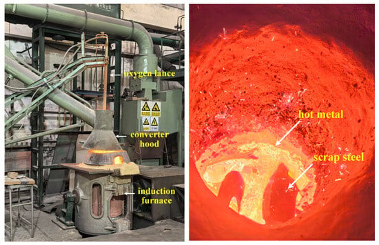
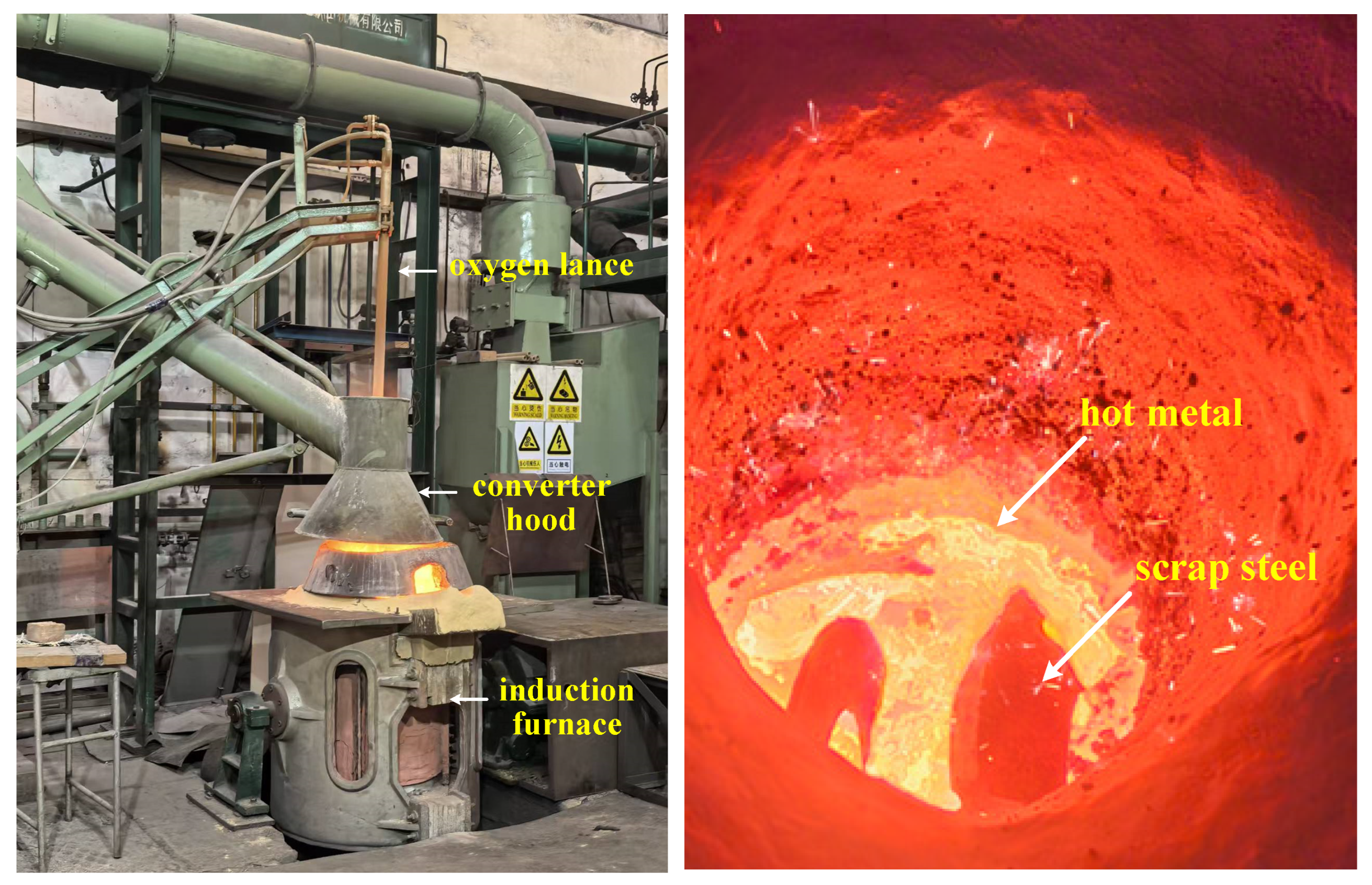
The experimental equipment consisted of a 500 kg medium–frequency induction furnace with heating capability (as shown in Figure 1). This setup is primarily used for heating and melting hot metal, preheating scrap steel, and conducting blowing operations during the process, while also enabling control and adjustment of the experimental temperature throughout the smelting stage. The inner cavity volume of the induction furnace is 0.073 m3, the heating power ranged from 0 to 250 kW, and the average heating rate is about 10 °C/min. The oxygen lance is equipped with an automatic lifting function, allowing the lance position to be adjusted according to the smelting requirements for oxygen supply. Gas-injection elements are installed at the furnace bottom to provide nitrogen for stirring the molten steel. A fume hood connected to a dust-removal system ensured a safe experimental environment. Other relevant experimental parameters are as follows: the induction furnace has an effective inner diameter of approximately 400 mm and a height of about 600 mm; the bottom–blowing element is arranged at the center of the furnace bottom, and the top-blowing oxygen lance adopts a four-hole nozzle structure; manual temperature measurement and sampling are used during the smelting process, with the measurement and sampling points located about 100 mm below the liquid surface to ensure that the obtained results are representative.
Figure 1.
The medium–frequency induction furnace.
Based on the conditions of the experimental induction furnace, a predetermined amount of pig iron and scrap steel is charged, with a total charge of approximately 150 kg. The chemical compositions of the pig iron and scrap steel used in the experiments are listed in Table 1. Considering the limited space of the induction furnace chamber, the melting efficiency of scrap steel, and the consistency of experimental results, the scrap steel added in the experiment is mainly in thin block form, with a thickness not exceeding 20 mm and a unit weight not exceeding 1.5 kg.
Table 1.
Chemical composition of pig iron and scrap used in the experiment, wt%.
3. Experimental Scheme and Procedure
3.1. Experimental Scheme
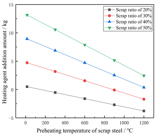
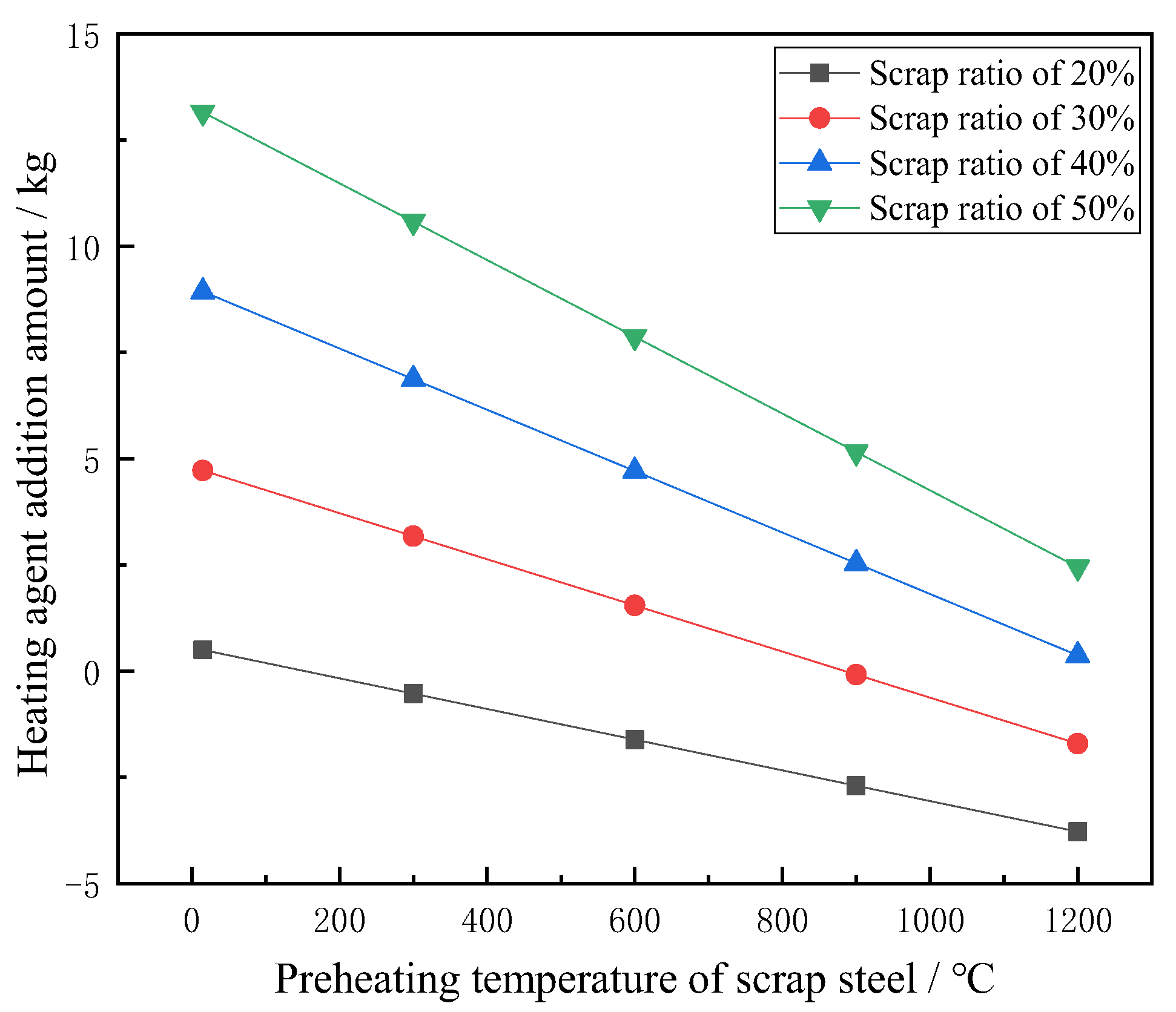
This experiment will conduct melting and smelting tests with four different scrap ratios: 20%, 30%, 40%, and 50%. Based on the above initial conditions, the required raw materials and the preheating temperature of the scrap are calculated using mass balance and heat balance. The corresponding amount of ferrosilicon heating agent to be added for each scrap ratio is shown in Figure 2. At a scrap ratio of 20%, the process is essentially in a critical state, and little to no supplemental heating is needed. As the scrap ratio increases further, more heat input is required to reach the target endpoint temperature of about 1600 °C. Preheating the scrap can effectively reduce the amount of heating agent needed, thereby mitigating the adverse effects of increased scrap on the smelting operation.
Figure 2.
Required heating agent addition for varying scrap ratios.
Based on the above calculations, the raw material formulation required for the hot-state experiments is established as shown in Table 2. According to the different scrap ratios, and considering the capacity of the induction furnace and the stability of the smelting process, four experimental schemes are designed. The charged pig iron ranges from 75 kg to 120 kg, and the scrap steel ranges from 30 kg to 75 kg. The scrap is preheated in the induction furnace to approximately 900−1000 °C. The ferrosilicon heating agent, lime, and magnesia are added according to the calculated amounts. The lump lime has a diameter of 10−30 mm and a CaO content of 99%; the magnesia particles have an average diameter of 5 mm and an MgO content of 97%; the ferrosilicon has a diameter of 10−30 mm and a Si content of 75%(The above experimental materials are sourced from JD.com, Beijing, China).
Table 2.
Raw material formulation.
3.2. Experimental Procedure
Step 1: According to the different charging schemes described above, the corresponding amount of pig iron is first charged. The induction furnace is then powered on for heating. After the pig iron is completely melted and the temperature reaches 1200–1300 °C, the scrap steel is added. For scrap ratios of 30% or higher, the scrap is preheated to 900–1000 °C. At this point, a hot metal sample is taken and the temperature is measured.
Step 2: Oxygen blowing is started and timed. The first batch of additives is introduced: half of the lime, all of the required magnesia, and the ferrosilicon heating agent are added from the top of the induction furnace. After 3 min of oxygen blowing, the second batch of additives, i.e., the remaining half of the lime, is added. The addition schedules for ferrosilicon heating agent, lime, and magnesia for the different experimental schemes are listed in Table 3. The oxygen supply intensity in Stage I is 2.8 Nm3∙min−1∙t−1, the lance height is 130–140 mm, and the bottom-blowing intensity is 0.15 Nm3∙min−1∙t−1. After the oxygen blowing time for Stage I specified in Table 4 is reached, hot metal and slag samples are taken, and the temperature is measured.
Table 3.
Addition system of ferrosilicon, lime and magnesia under different experimental schemes.
Table 4.
Oxygen blowing time settings under different experimental schemes.
Step 3: Oxygen blowing in Stage II is continued. The oxygen supply intensity in Stage II is 3.0 Nm3∙min−1∙t−1, the lance height is 120–130 mm, and the bottom-blowing intensity is 0.05 Nm3∙min−1∙t−1. After the oxygen blowing time for Stage II specified in Table 4 is reached, hot metal and slag samples are taken, and the temperature is measured.
Step 4: Oxygen blowing in Stage III is continued. The oxygen supply intensity in Stage III is 3.0 Nm3∙min−1∙t−1, the lance height is 120–130 mm, and the bottom-blowing intensity is 0.10 Nm3∙min−1∙t−1. After the oxygen blowing time for Stage III specified in Table 4 is reached, molten steel and slag samples are taken, and the temperature is measured.
Step 5: Slag is skimmed, and the steel is tapped, marking the end of the experiment.
During the experiment, increasing the bottom-blowing intensity in the early stage of smelting is beneficial for improving the dynamic conditions of bath stirring and promoting rapid scrap melting. Properly controlling the top-blowing intensity and lance height not only ensures an adequate heating rate of the bath but also maintains a certain level of iron oxide generation in the slag, enhancing slag formation rate and dephosphorization efficiency. In the middle stage of smelting, reducing the bottom–blowing intensity helps control the decarburization rate, preventing splashing and slag dry–up. In the final stage, increasing the bottom-blowing intensity and oxygen supply intensity accelerates the decarburization and heating rate of the bath, reduces the oxidizability of the molten steel, and promotes the reaction to reach equilibrium at the end of smelting.
4. Analysis of Experimental Results Under Different Scrap Ratios
4.1. Variation in Temperature and Carbon, Silicon, and Phosphorus Content During the Smelting Process
4.1.1. Bath Temperature During Smelting
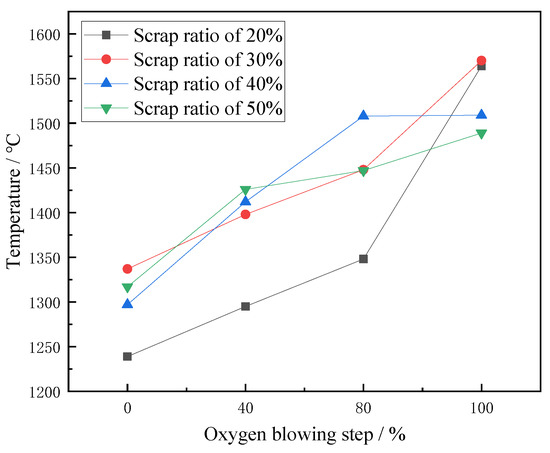
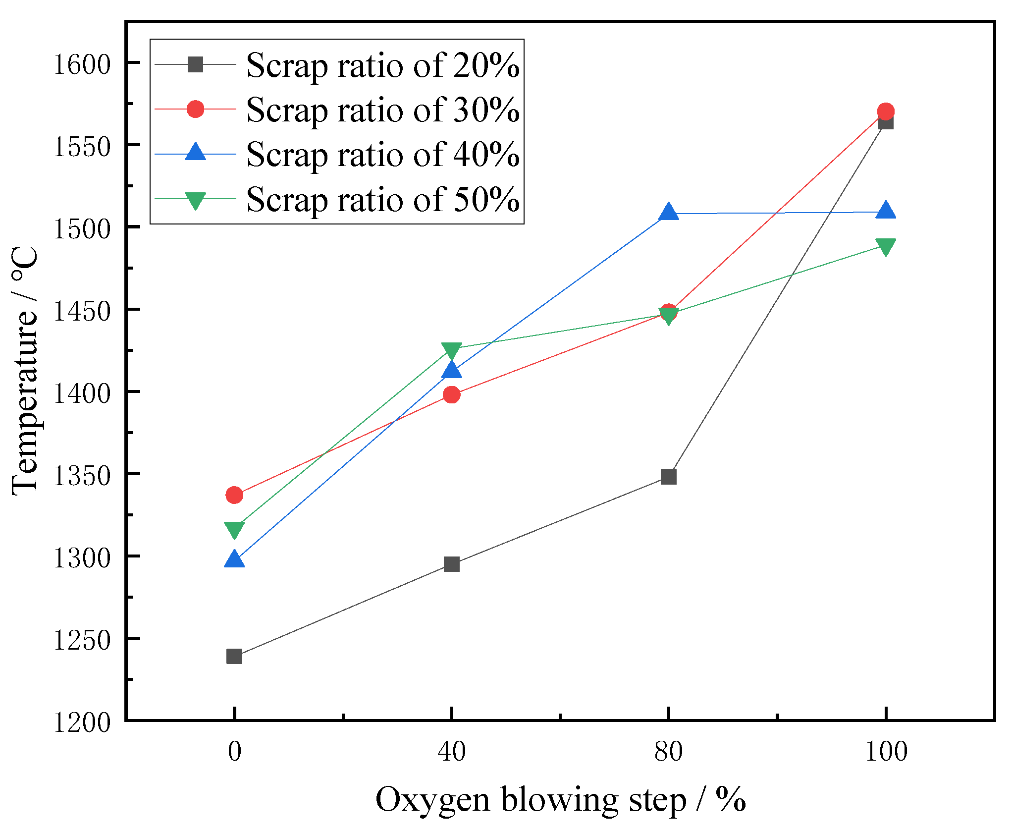
During the smelting process, the bath temperature is measured via thermocouple contact at the start of blowing, as well as at the 40%, 80%, and 100% blowing point. The variation in bath temperature under different scrap ratios is shown in Figure 3. As can be seen from Figure 3, there are certain differences in the initial temperatures for different scrap ratios from hot metal melting to the start of oxygen blowing. The initial bath temperature at a 20% scrap ratio is 1239 °C, while the initial temperatures for scrap ratios of 30–50% ranged between 1290 °C and 1340 °C. The issue of scrap preheating is considered in the experiments with different scrap ratios. In the 20% scrap ratio experiment, the scrap is not preheated, whereas in the other experiments, the scrap is preheated to 900–1000 °C. It is evident that scrap preheating has a noticeable effect on the initial smelting temperature.
Figure 3.
Variation in bath temperature during smelting with different scrap ratios.
During the smelting process, the bath temperature in all experimental groups showed a generally steady upward trend. In the groups with 20% and 30% scrap ratios, the bath temperature increased significantly during the oxygen blowing step from 80% to 100%. This may be because when the scrap addition is lower, the scrap melts relatively earlier, so the temperature rises more rapidly in the later stage of smelting. In the groups with 40% and 50% scrap ratios, due to the larger scrap addition, the scrap melts more slowly, resulting in a relatively gradual rise in bath temperature. Even with supplemental heating measures, the endpoint temperatures are comparatively lower.
4.1.2. Bath Carbon Content During Smelting
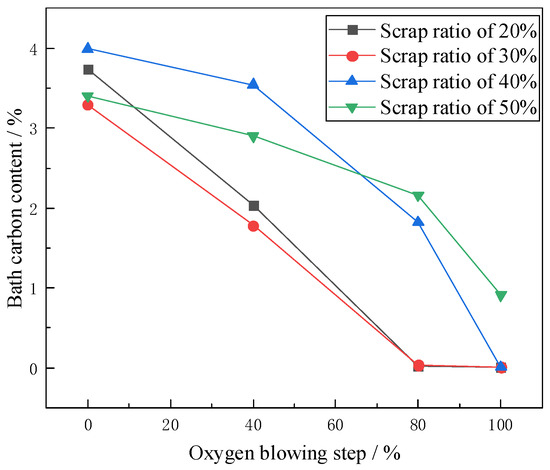
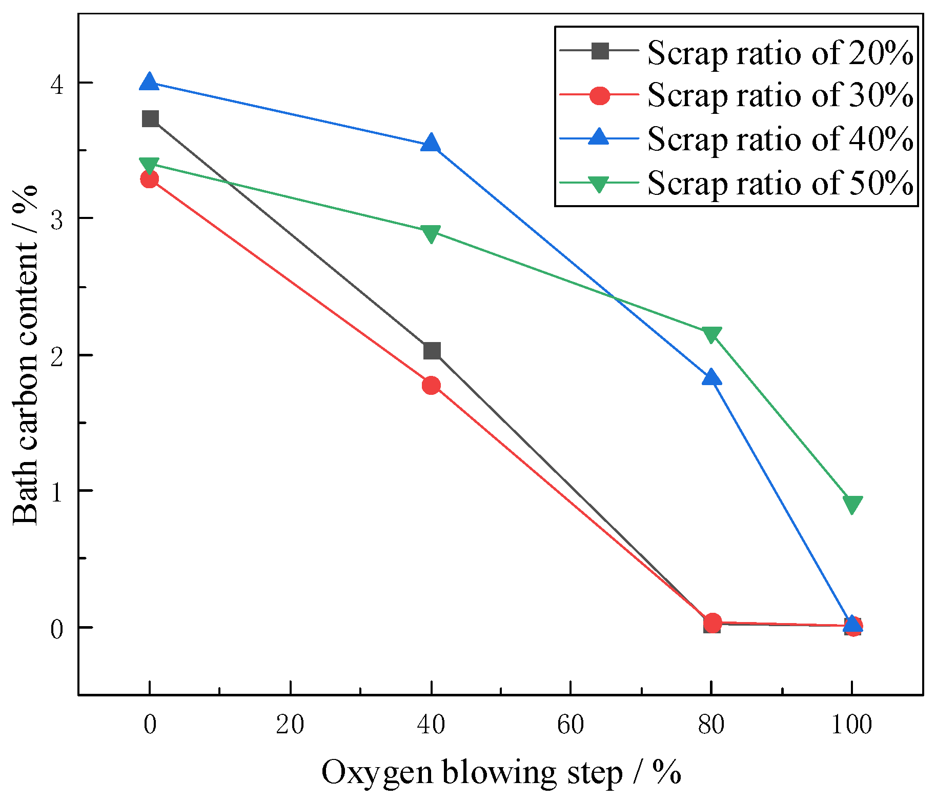
During the smelting process, steel samples are taken with a sampler at the start of blowing, as well as 40%, 80%, and 100% blowing point, and their compositions are analyzed by fluorescence spectrometry. The variation in bath carbon content under different scrap ratios is shown in Figure 4. It can be seen from Figure 4 that the bath carbon content continuously decreases during smelting for all scrap ratios, but the trends differ. In the experiments with 20% and 30% scrap ratios, the decreasing trends of carbon content are essentially similar. The change in carbon content in the early stage is mainly influenced by the combined effects of decarburization via oxygen blowing and scrap melting. In the experiments with 20% and 30% scrap ratios, scrap melting is relatively effective in the early stage, whereas in the experiments with 40% and 50% scrap ratios, the carbon content remained at a relatively high level in the early and middle stages, indicating unsatisfactory scrap melting. Only when the oxygen blowing step reached 80% to 100% did the carbon content begin to drop sharply. This is because the scrap melts at the higher temperature, and under the combined effect of oxygen blowing, the bath carbon content decreases rapidly. Moreover, in the experiment with a 50% scrap ratio, the overall decrease in bath carbon content is very slow. An excessively high scrap ratio not only results in poorer dynamic conditions of the bath but also reduces oxygen efficiency, leading to unsatisfactory bath reactions and affecting the time required to complete decarburization at the endpoint. Therefore, as the scrap ratio increases, industrial application must consider the impact of scrap melting on the decarburization reaction and adjust the operational parameters of the smelting process.
Figure 4.
Variation in bath carbon content during smelting with different scrap ratios.
4.1.3. Bath Silicon Content During Smelting
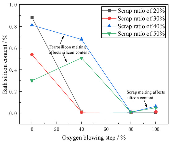
Through process sampling, the variation in bath silicon content under different scrap ratios is shown in Figure 5. It can be seen from the figure that the silicon content curves differ significantly among the experimental groups with different scrap ratios. In conventional converter smelting, silicon is usually oxidized and enters the slag at the earliest stage, and the silicon content in the bath becomes a trace amount after about 3 min. In these experiments, the change in silicon content is influenced not only by oxygen oxidation and scrap melting but also by ferrosilicon melting.
Figure 5.
Variation in bath silicon content during smelting with different scrap ratios.
In the experiments with 20% and 30% scrap ratios, silicon is almost completely oxidized when the oxygen blowing step reached 40%. For the purpose of supplemental heating, 0.5 kg and 2.5 kg of ferrosilicon are added in the experiments with 40% and 50% scrap ratios, respectively. The addition of ferrosilicon significantly affects the variation of silicon content in the bath during smelting. In the experiment with a 50% scrap ratio, the silicon content even shows an increasing trend. Because silicon continuously participates in oxidation reactions—especially in the 50% scrap ratio experiment—it also influences carbon oxidation to some extent. Referring to Figure 4, it can be seen that precisely because silicon continued to be oxidized, the change in bath carbon content in the 50% scrap ratio experiment is not obvious. Only after the oxygen blowing step reached 80%, when silicon oxidation is essentially complete, did the decarburization rate begin to show an inflection point. Furthermore, during the oxygen blowing step from 80% to 100%, the silicon content in the experiments with 40% and 50% scrap ratios shows a slight increase, indicating that the scrap does not completely melt at that time and releases some silicon.
4.1.4. Bath Phosphorus Content During Smelting
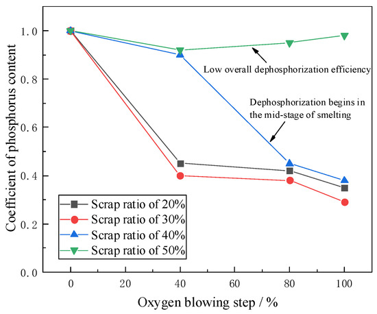
Through process sampling, the variation in dephosphorization rate under different scrap ratios is shown in Figure 6. To visually compare the dephosphorization effect under different scrap ratios, the initial phosphorus content is normalized. The comparison shows that at scrap ratios of 20% and 30%, the dephosphorization rate in the early smelting stage can exceed 50%. In the early stage, the bottom-blowing intensity is increased, which helps improve bath stirring, promote bath temperature rise, and facilitate slag formation and dephosphorization. When the scrap ratio reaches 40% and 50%, the thermodynamic and dynamic conditions of the bath changes significantly. Even with scrap preheating measures, the dephosphorization rate in the early stage is still less than 10%. In the 40% scrap ratio experiment, the dephosphorization effect improves significantly only when the oxygen blowing step reaches 40–80%. At that time, as the scrap melts and the basicity increases, the conditions for dephosphorization are greatly improved. This indicates that as the scrap ratio increases, the timing of the dephosphorization reaction is delayed, gradually shifting from early–stage to later-stage dephosphorization. In the 50% scrap ratio experiment, due to the excessively high scrap ratio, the dynamic conditions of the bath are poor, and a relatively large amount of ferrosilicon is added to supplement heat, making it difficult to raise the basicity during smelting. Consequently, the dephosphorization effect remains poor throughout the entire process.
Figure 6.
Variation in dephosphorization rate during smelting with different scrap ratios.
4.2. Slag Formation Variation During the Smelting Process
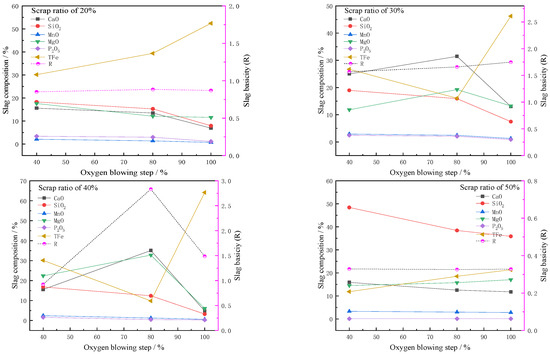
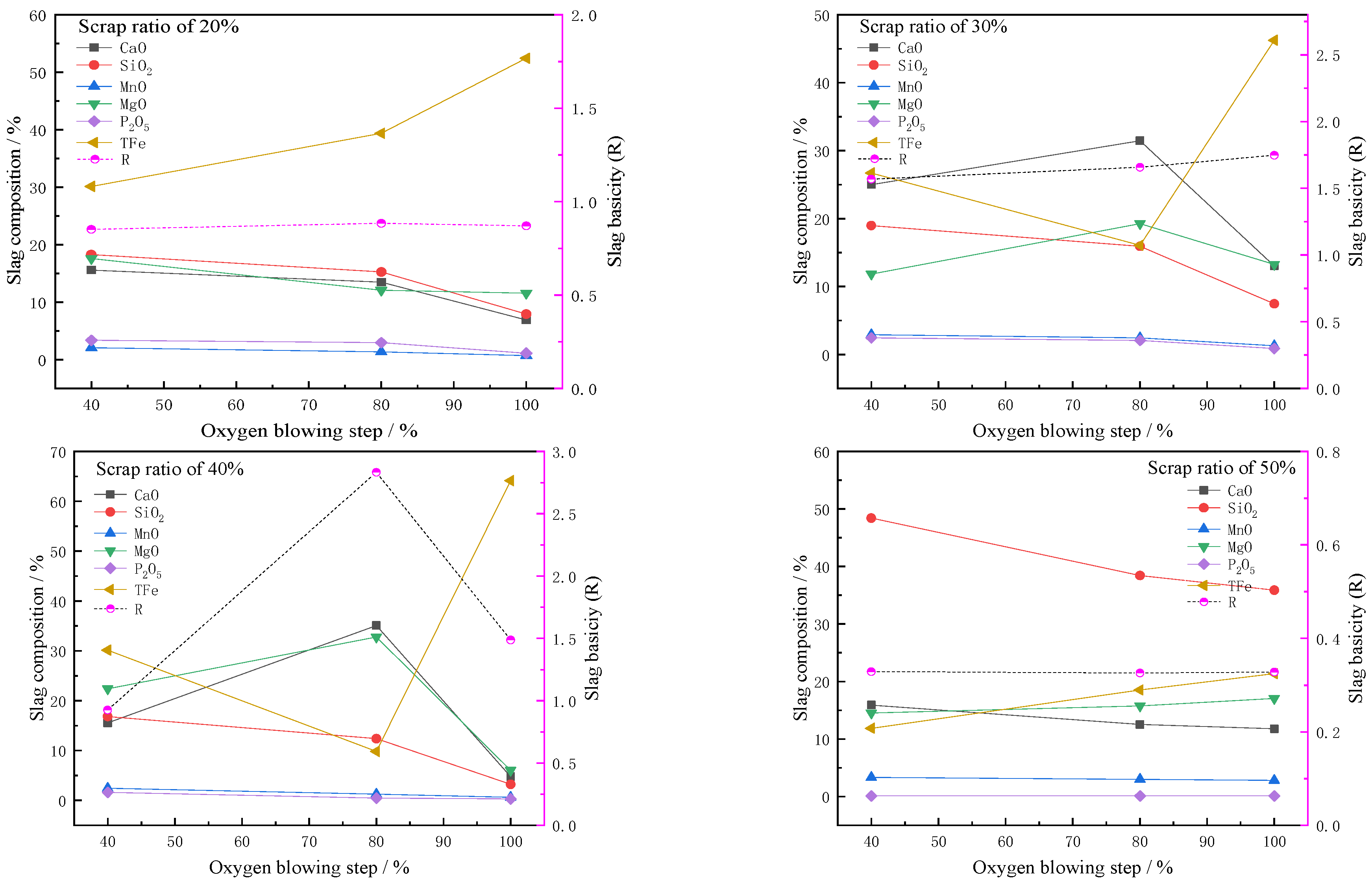
By sampling slag at different time intervals during the smelting process, variations in slag composition under different scrap ratios are obtained, as shown in Figure 7. From the figure, it can be seen that in experiments with different scrap ratios, the TFe content in the slag accounts for a relatively high proportion. This is primarily due to the high addition of scrap leading to significant oxidation of iron during the smelting process. The TFe content has a considerable influence on other components of the slag. In the experiment with a 20% scrap ratio, except for the increase in TFe content, other components in the slag sampled at different oxygen blowing stages generally show a downward trend, with the slag basicity maintained between 0.85 and 0.88. In the experiments with 30% and 40% scrap ratios, as the scrap is preheated, the lime dissolution efficiency improves, and the CaO content gradually increases. The basicity for the 30% scrap ratio is between 1.57 and 1.75, and for the 40% scrap ratio, it is between 0.93 and 2.83, reaching its highest at the 80% oxygen–blowing stage. At the end of smelting, due to scrap melting and a significant increase in TFe content, the proportion of CaO decreases. In the experiment with a 50% scrap ratio, the slag variation pattern is different. Because a larger amount of ferrosilicon is added as a heating agent, the proportion of SiO2 during smelting exceeds 30%. Simultaneously, the high scrap ratio results in an overall slower lime melting rate. The TFe content in the slag gradually rises, while the P2O5 content remains relatively low overall. The basicity stays around 0.33, which is the main reason for the poor dephosphorization effect under these conditions.
Figure 7.
Variation in slag composition during smelting with different scrap ratios.
Additionally, the experiments reveal another phenomenon: the MgO content in the slag under different scrap ratios is generally above 10%. This is mainly because, during the initial stage of smelting, the low bath temperature leads to a slower overall lime dissolution rate. The low-basicity slag formed reacts chemically with the MgO–based furnace lining refractory material, causing erosion of the lining. Observation shows that the higher the scrap ratio, the faster the lining erosion. On one hand, increasing the scrap ratio in the converter intensifies the impact damage on the lining surface; on the other hand, lower slag basicity and higher FeO content promote the formation of (Mg,Fe)O solid solution. Therefore, it is necessary to improve the high-temperature strength of the magnesia-carbon brick lining, while rapidly increasing the bath temperature and basicity in the early stage of smelting, and also enhancing the saturation of MgO in the slag.
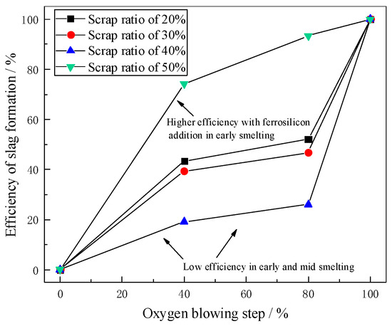
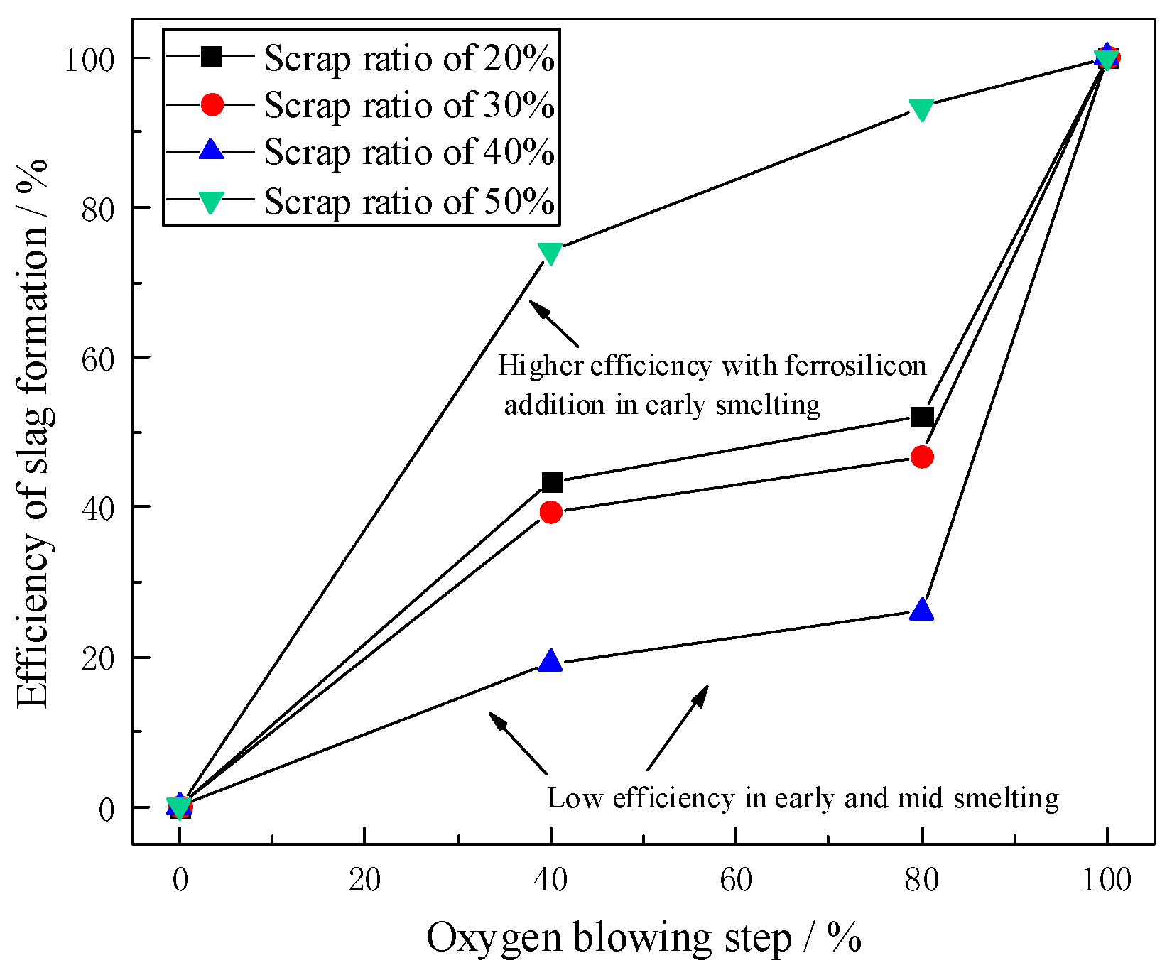
By calculating the ratio of slag generated at different stages of the smelting process to the total slag volume, the slag formation efficiency for different scrap ratios is obtained, as shown in Figure 8. When the scrap ratio is 20% or 30%, the slag formation efficiency in the early stage is high, reaching about 40%. When the scrap ratio is 40%, the slag formation efficiency in the early smelting stage is less than 20%, and in the middle stage, it is less than 30%. The low efficiency in both the early and middle stages indicates that, under a 40% scrap ratio, a large amount of unmelted scrap inhibits the slagging effect during the process. The slag formation efficiency begins to increase rapidly only in the later stage as the scrap gradually melts. When the scrap ratio is 50%, although the scrap addition is highest, the slag formation efficiency in the early smelting stage is the highest, exceeding 70%. This is primarily because the addition of a significant amount of ferrosilicon before smelting generates a large volume of low–basicity, low–melting–point slag.
Figure 8.
Efficiency of slag formation during smelting with different scrap ratios.
4.3. Phase Petrographic Analysis of Dephosphorization Slag During Smelting
To further investigate the reaction behavior of phosphorus during the smelting process, the slag samples from experiments with different scrap ratios are analyzed in depth. The analysis mainly includes observing the phases via scanning electron microscopy (SEM) and determining the approximate composition through energy-dispersive spectroscopy (EDS). The collected slag samples (taken at 40%, 80%, and 100% of the oxygen blowing step) are mounted in resin, then ground, polished, cleaned, dried, and coated with a gold film in a vacuum environment before SEM-EDS observation.
4.3.1. Experiment with 20% Scrap Ratio
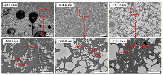
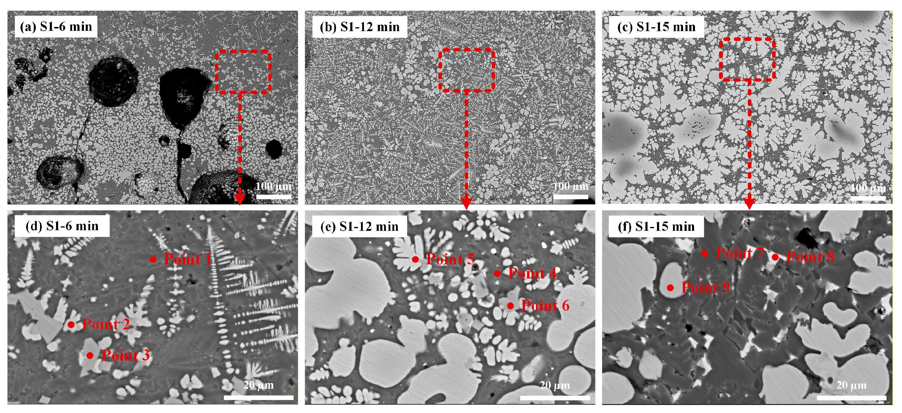
The SEM images and EDS results of the dephosphorization slag from the 20% scrap ratio experiment (denoted as S1) are shown in Figure 9 and Table 5, respectively. When the oxygen blowing step reaches 40%, a two–phase structure begins to form in the slag, with phosphorus mainly enriched in the CaO–SiO2 matrix phase. In Point 1, P2O5 is 3.09%, and the contents of CaO and SiO2 are high, while in the iron-rich phases (Points 2 and 3), P2O5 is only about 0.7%. This indicates that phosphorus preferentially enters the slag phase containing CaO rather than the FeO-rich regions.
Figure 9.
SEM map of dephosphorization S1 slag.
Table 5.
EDS composition of S1 dephosphorization slag.
At 80% oxygen blowing step, P2O5 in the matrix phase rises to 3.82% (Point 4), the highest among the three stages, suggesting active dephosphorization with continuous migration of phosphorus into the slag and concentration in the CaO–rich phase. P2O5 in the iron-rich phase remains low, indicating that the iron-rich phase is not the main location for phosphorus at this stage.
At 100% oxygen blowing step, the FeO content in the slag further increases, P2O5 in the matrix phase remains at 2.7% (Point 7), and the phosphorus content in the iron–rich phase is still near zero. Dephosphorization nears completion in the later stage of smelting, and the phosphorus distribution in the slag stabilizes.
4.3.2. Experiment with 30% Scrap Ratio
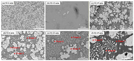
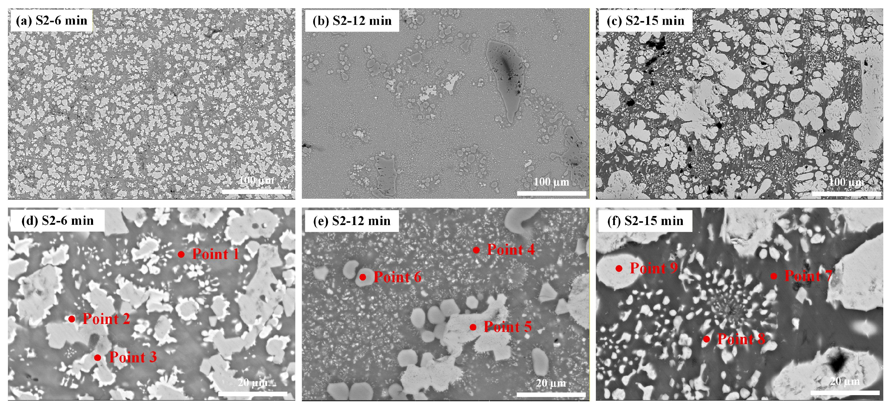
The SEM images and EDS results of the dephosphorization slag from the 30% scrap ratio experiment (denoted as S2) are shown in Figure 10 and Table 6, respectively. When the oxygen blowing step reaches 40%, a distinct two-phase structure forms in the slag. Point 1 shows high CaO and SiO2 contents, with P2O5 reaching 4.33%, indicating phosphorus enrichment in the CaO–SiO2 matrix phase. Point 2 is an iron-rich phase, and phosphorus hardly enters the iron oxide phase. At this stage, the slag composition shows TFe of 26.72% and a basicity of 1.57, which favors phosphorus transfer into the slag.
Figure 10.
SEM map of dephosphorization S2 slag.
Table 6.
EDS composition of S2 dephosphorization slag.
At 80% oxygen blowing step, SEM reveals a more continuous matrix phase with finer particles. The slag basicity reaches 1.66, enhancing dephosphorization capability. EDS results show Point 4 remains a high CaO–SiO2 phase (P2O5 3.20%), while Points 5 and 6 exhibit high FeO and MgO, forming an iron–magnesium oxide phase with low P2O5 content.
At 100% oxygen blowing step, the slag TFe and basicity further increase. Point 7 is a typical CaO–SiO2 matrix phase (P2O5 2.33%), and dephosphorization continues in the later stage of smelting. Points 8 and 9 are iron-rich phases with low P2O5.
4.3.3. Experiment with 40% Scrap Ratio
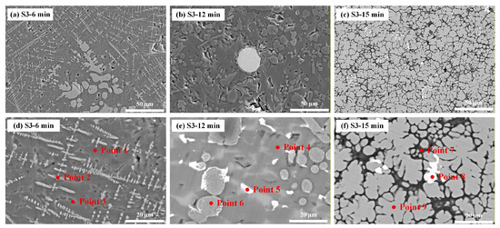
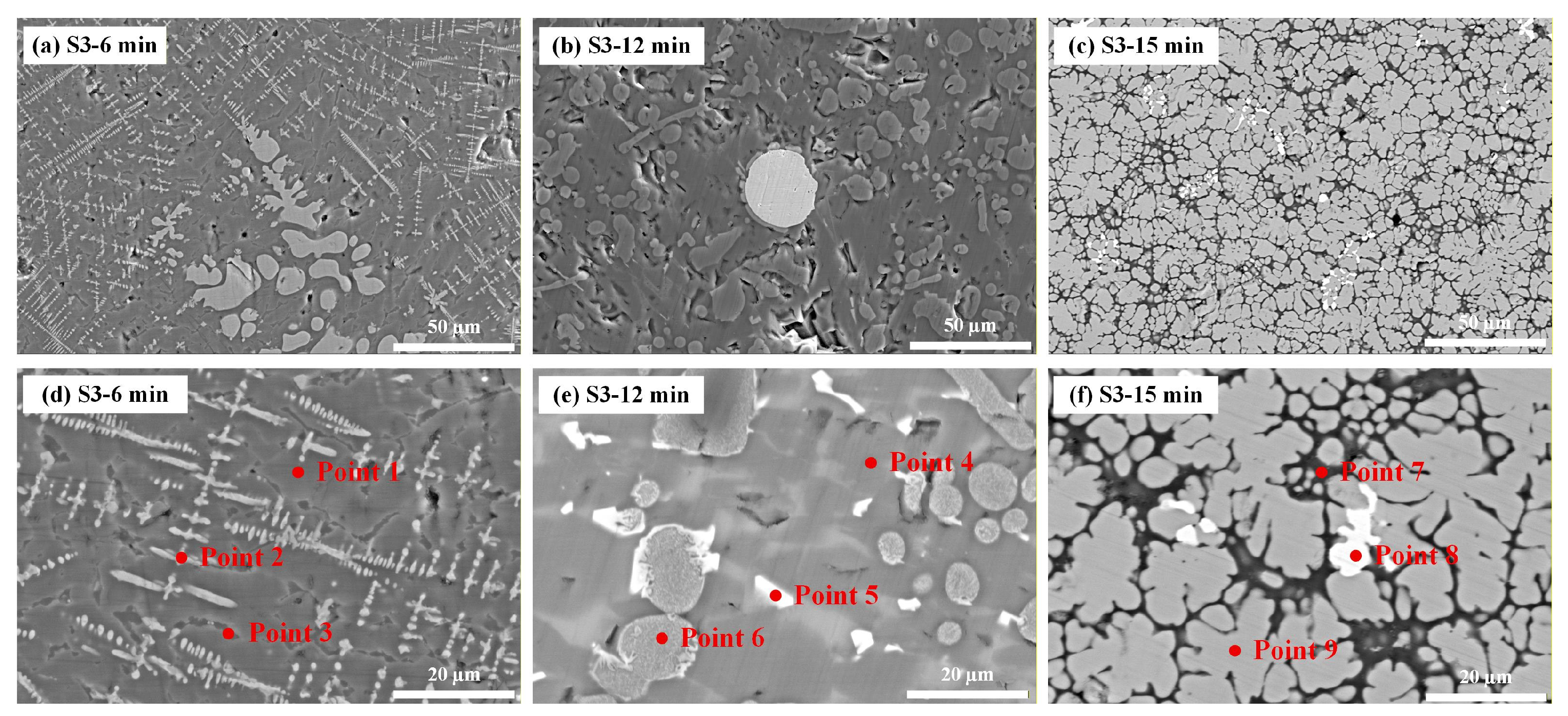
The SEM images and EDS results of the dephosphorization slag from the 40% scrap ratio experiment (denoted as S3) are shown in Figure 11 and Table 7, respectively. When the oxygen blowing step reaches 40%, EDS results indicate fine slag grains with a silicate matrix as the main phase. Point 1 is a CaO–SiO2–FeO matrix phase, with some phosphorus enriched in the CaO–containing matrix. Points 2 and 3 are typical iron-rich phases, and phosphorus is hardly enriched there.
Figure 11.
SEM map of dephosphorization S3 slag.
Table 7.
EDS composition of dephosphorization slag.
At 80% oxygen blowing step, the slag composition changes significantly, with substantial increases in CaO and MgO contents and basicity rising to 2.83. A multiphase structure forms in the slag: SEM shows a more continuous matrix phase, and EDS identifies Point 4 as a high CaO–SiO2 phase, while Points 5 and 6 are MgO–rich and iron–containing phases, respectively. The slag at this stage exhibits high basicity, enabling rapid dephosphorization, and phosphorus fully enriches in the dicalcium silicate phase.
At 100% oxygen blowing step, slag TFe increases sharply to 64.17%, while CaO and SiO2 decrease significantly, lowering the basicity to 1.49. SEM reveals extensive formation of bright white iron-rich phases. EDS shows Points 7 and 9 as CaO–SiO2–FeO composite phases (P2O5 about 2–2.5%), and Point 8 as a typical iron-rich phase. In the later stage of smelting, iron oxides in the slag increase markedly; excessively high FeO reduces the proportion of CaO in the slag, diminishing dephosphorization ability.
4.3.4. Experiment with 50% Scrap Ratio
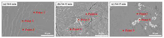
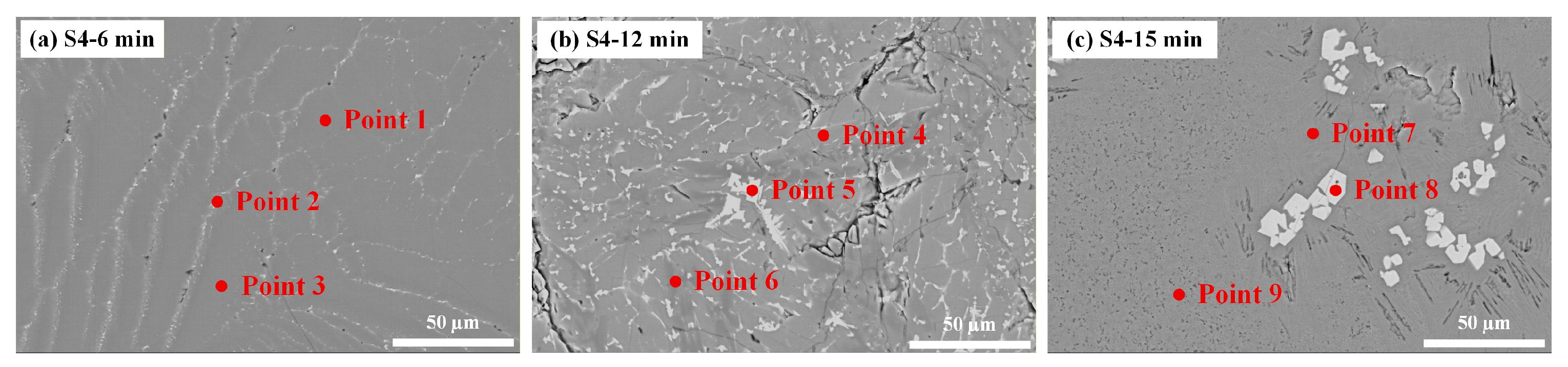
The SEM images and EDS results of the dephosphorization slag from the 50% scrap ratio experiment (denoted as S4) are shown in Figure 12 and Table 8, respectively. SEM–EDS results indicate that the silicate matrix, rich in SiO2, is the dominant phase in all stages. At 40% oxygen blowing step, Points 1–3 show SiO2 content as high as 35–50%, CaO only about 12–19%, and P2O5 only about 0.8–1.0%, indicating no significant phosphorus enrichment. At 80% and 100% oxygen blowing steps (Points 4–8), the high-SiO2 phase remains dominant; FeO content increases (about 17–35%), but P2O5 stays at a low level without forming distinct phosphorus-rich phases.
Figure 12.
SEM map of dephosphorization S4 slag.
Table 8.
EDS composition of S4 dephosphorization slag.
Overall, the S4 dephosphorization slag exhibits high SiO2, low CaO, and low basicity. No stable high-basicity phosphorus–containing phase forms in the slag, and SEM shows no obvious phosphorus-rich particles. This indicates insufficient driving force for dephosphorization under these conditions, and phosphorus does not effectively transfer into the slag, which is consistent with the previously described relationship between phosphorus changes in the molten steel and slag.
4.4. Analysis of Slag-Forming Path During the Smelting Process
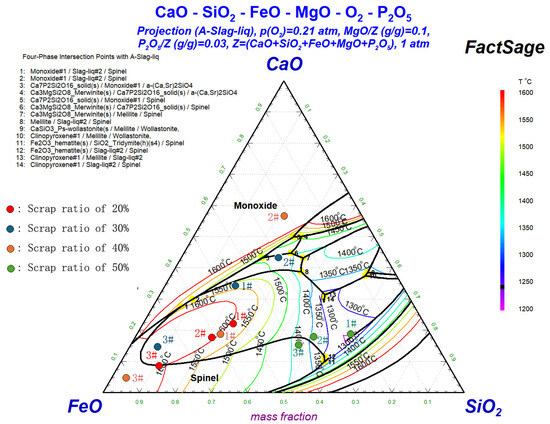
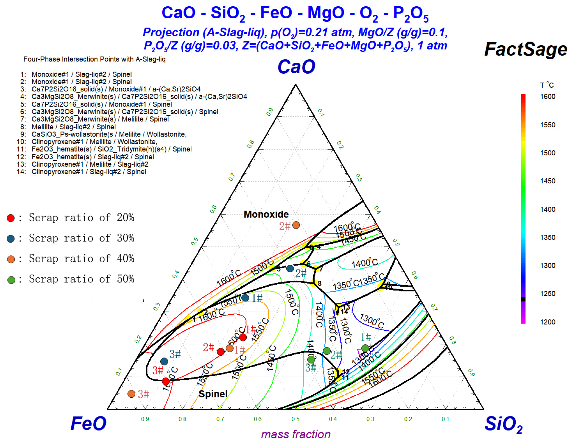
Using FactSage thermodynamic calculation software, the slag compositions at different blowing steps under varying scrap ratios are plotted in the CaO–SiO2–FeO slag system phase diagram, as shown in Figure 13. In the diagram, 1#, 2#, and 3# represent the time points at 40%, 80%, and 100% of the oxygen blowing steps, respectively.
Figure 13.
Slag distribution in the phase diagram at different blowing steps and scrap ratios.
Under the 20% scrap ratio, the slag evolution from 1# to 3# is summarized as follows: during the initial stage, a multiphase primary slag of CaO–SiO2–FeO–MgO forms; in the middle stage, increased FeO promotes lime dissolution and phosphorus migration; and in the final stage, an iron-rich slag is formed. The main characteristics of this process are: the slag continuously shifts toward the FeO end, with gradually increasing oxidizability, yet overall remains near regions of high liquidus temperature and the Spinel phase, indicating insufficient liquid-phase development and a strong tendency for solid-phase precipitation.
Under the 30% scrap ratio, the slag evolution from 1# to 3# is summarized as: initial formation of CaO–SiO2–FeO primary slag; sufficient dissolution of CaO and improved liquid fraction in the middle stage, enhancing dephosphorization; and rapid increase in FeO in the final stage, forming an iron-rich final slag. The main features are: improved lime dissolution capacity and slag-phase homogenization during the process, which facilitates stable phosphorus transfer into the slag.
Under the 40% scrap ratio, the slag evolution from 1# to 3# is outlined as: formation of a low-basicity Spinel primary slag in the initial stage; substantial entry of CaO and MgO into the slag and a significant rise in basicity in the middle stage; and a sharp increase in FeO in the final stage, transforming the slag into an iron-rich slag. The key characteristic is the high slag basicity in the middle stage, which promotes phosphorus migration and stable fixation in the slag, though the slag-forming path shows considerable fluctuation.
Under the 50% scrap ratio, the slag evolution from 1# to 3# is described as: formation of a high-SiO2 acidic primary slag in the initial stage; a gradual increase in FeO promoting partial liquid-phase formation in the middle stage; and formation of a low-basicity, silicate-rich slag with weak dephosphorization ability in the final stage. The main feature is the relatively good liquid-phase development during the process; however, the acidic nature of the slag system makes it difficult to fix phosphorus stably.
4.5. Phosphorus Distribution Ratio in the Smelting Process
Table 9 presents a comparison between the equilibrium phosphorus distribution ratio calculated using the Suito model [30] and the actual distribution ratio under different experimental conditions. Additionally, LP is the ratio of phosphorus in slag to that in molten steel. The results show that in the experiments with 20% scrap ratio, the actual phosphorus distribution ratio ranges from 3.6 to 10.6; in the 30% scrap ratio experiments, it ranges from 19.4 to 38.4; in the 40% scrap ratio experiments, it ranges from 2.8 to 6.3; and in the 50% scrap ratio experiments, it ranges from 0.38 to 0.40. The experimental group with 30% scrap ratio exhibits the highest phosphorus distribution ratio, followed by the 20% group, while the 50% group shows the lowest. The 30% scrap ratio group employs scrap preheating, which facilitates scrap melting and slag formation for dephosphorization during smelting. In contrast, the 50% scrap ratio group has the highest scrap addition, the poorest kinetic conditions, and the addition of ferrosilicon further worsens the dephosphorization conditions, leading to overall unsatisfactory dephosphorization.
Table 9.
LP under different experimental conditions.
Overall, the phosphorus distribution ratios at 40% and 80% oxygen blowing steps are higher than those at 100% oxygen blowing, indicating that the dephosphorization reaction predominantly occurs during the middle and early stages of smelting. Additionally, the equilibrium phosphorus distribution ratio is significantly higher than the actual distribution ratio. Due to the limitations of the experimental conditions, the reactions in this experimental process do not reach thermodynamic equilibrium, and the dephosphorization reaction is constrained by kinetic conditions. Meanwhile, the insufficient liquefaction of the experimental slag system results in effective basicity and FeO activity lower than the assumed values in the model, while thermodynamic deviations caused by bath temperature drop and temperature gradients, as well as changes in slag composition due to MgO lining erosion, also significantly reduce the measured partition ratio.
5. Conclusions
- (1)
- Through 500 kg induction furnace experiments, the heating reaction and dephosphorization effect during the smelting process with scrap ratios ranging from 20% to 50% are analyzed. When the scrap ratio is 20% to 30%, the dephosphorization rate in the early stage of smelting reaches over 50%; when the scrap ratio is 40% to 50%, the dephosphorization rate in the early stage is less than 10%. A continuously increasing scrap ratio leads to a decrease in bath temperature, a slowdown in scrap melting rate, an increase in metal viscosity, poorer bath stirring effect, and a delay in the dephosphorization timing. Under such conditions, enhancing the later-stage dephosphorization effect may be a better approach.
- (2)
- According to SEM and EDS analysis, when the scrap ratio is 20% to 30%, suitable basicity and temperature are formed in the middle and early stages of smelting, and phosphorus is basically enriched in the CaO–SiO2 matrix phase without entering the FeO-rich region. When the scrap ratio is 40%, the slag exhibits high basicity characteristics in the middle stage, and phosphorus begins to be heavily enriched in the dicalcium silicate phase. When the scrap ratio is 50%, the silicate matrix is the dominant phase at all stages, and no obvious phosphorus-rich phase is formed.
- (3)
- When the scrap ratio is 30%, the dissolution of CaO during smelting is relatively sufficient, the liquid fraction of slag increases, and phosphorus is stably transferred into the slag, resulting in the highest actual phosphorus partition ratio among all tested ratios, while the 50% scrap ratio gives the lowest value. A moderate scrap ratio, together with measures such as scrap preheating and supplemental heating, as well as an increased bottom-blowing intensity during the smelting process, is beneficial for the dephosphorization mass transfer reaction under high scrap ratio conditions.
Author Contributions
Conceptualization, Z.J.; methodology, L.Y. and W.W.; software, G.J. and Y.D.; validation, C.W. and G.J.; formal analysis, G.W., Y.D. and G.J.; data curation, G.W.; writing—original draft preparation, C.W.; writing—review and editing, Z.J., L.Y. and W.W. All authors have read and agreed to the published version of the manuscript.
Funding
This research was funded by National Key R&D Program of China, grant number 2024YFB3713903.
Data Availability Statement
The data presented in this study are available on request from the corresponding author (The data are not publicly available due to privacy).
Conflicts of Interest
No potential conflict of interest was reported by the authors, and the funders had no role in the design of the study; in the collection, analyses, or interpretation of data; in the writing of the manuscript; or in the decision to publish the results.
References
- Tian, C.J.; Zang, X.M.; Zhang, L.W.; Zhang, Y.J.; Kong, L.Z.; Wang, Z.Y. Development status and discussion on high scrap steel ratio converter steelmaking technology. J. Iron Steel Res. 2024, 36, 692–706. [Google Scholar]
- Szekely, J.; Chuang, Y.K.; Hlinka, J.W. The melting and dissolution of low-carbon steels in iron-carbon melts. Metall. Trans. 1972, 3, 2825–2833. [Google Scholar] [CrossRef] [Scilit]
- Shukla, A.K.; Deo, B.; Robertson, D.G.C. Scrap dissolution in molten iron containing carbon for the case of coupled heat and mass transfer control. Metall. Mater. Trans. B 2013, 44, 1407–1427. [Google Scholar] [CrossRef] [Scilit]
- Wang, C.; Brämming, M.; Larsson, M. Numerical model of scrap blending in BOF with simultaneous consideration of steel quality, production cost, and energy use. Steel Res. Int. 2013, 84, 387–394. [Google Scholar]
- Assis, A.N.; Warnett, J.; Spooner, S.; Fruehan, R.J.; Sridhar, S. Spontaneous emulsification of a mental drop immersed in slag due to dephosphorization: Surface area quantification. Metall. Mater. Trans. B 2015, 46, 568–576. [Google Scholar] [CrossRef] [Scilit]
- Liu, Y.S.; Gao, J.P.; Han, Y.; Deng, G.C. Mathematical model of scrap melting process simulated by ice in water model experiments. J. Iron Steel Res. 1992, 4, 15–21. [Google Scholar]
- Yang, W.Y.; Zhang, X.G.; Wang, M.L.; Gao, W.T.; Cui, H.Z.; Bai, Y. Movement of scrap in the bath of converter. Iron Steel 2013, 48, 24–29. [Google Scholar]
- Zhao, C.L.; Wang, C.Y.; Sun, Y.H.; Wang, Z.; Shen, H.J. Physical simulation study of a 300t duplex combined blown dephosphorization converter. J. Iron Steel Res. 2015, 27, 42–47. [Google Scholar]
- Yang, W.Y.; Jiang, X.F.; Li, L.; Peng, X.Y.; Wang, M.L.; Shi, X.Q. Thermal simulation study on the melting of scrap. Iron Steel Scrap China 2016, 3, 18–28. [Google Scholar]
- Pei, K.H.; Chen, C.; Zhao, Y.; Lin, Y.C.; Yang, R.W.; Zhu, J.J.; Wang, T.; Yang, K.; Lin, W.M. Water model experiment on the motion, melting, and mixing of scrap in bottom stirred reactors. Chin. J. Process Eng. 2022, 22, 1601–1612. [Google Scholar]
- Li, J.Z.; Ma, D.G.; Wang, J.X.; Ma, X.C.; Wu, G.H. Influence of high scrap ratio on steel-making process. Hebei Metall. 2017, 7, 67–69. [Google Scholar]
- Liu, L. Development of high scrap steel ratio and efficient energy saving new processes for converter. In Proceedings of the Conference on Converter Steelmaking Technology Exchange, Steelmaking Society of CSM, Nanchang, China, 27–28 March 2018. [Google Scholar]
- Schafer, K.; Geck, H.; Pretzer, G.; Selenz, H.J.; Patel, P. Advances in the K(M)S process at the georgsmarienhutte works of klockner-stahl. Iron Steelmak. 1988, 15, 29–32. [Google Scholar]
- Zhang, J.Y.; He, Y.D.; Sahai, Y. Mathematical modeling of post combustion in basic oxygen steelmaking furnaces. J. Combust. Sci. Technol. 2000, 6, 115–119. [Google Scholar]
- Wan, X.F.; Zhang, G.Y.; Lin, D.; Zou, Z.S. Application of exhaust gas analysis in investigating bath temperature in BOF. China Metall. 2006, 9, 19–23. [Google Scholar] [CrossRef] [Scilit]
- Yang, J.D.; Qi, B.S.; Guo, B.W. Research of the postcombustion technology of BOF. Energy Metall. Ind. 2011, 30, 34–38. [Google Scholar]
- Ahmed, H. New trends in the application of carbon-bearing materials in blast furnace iron-making. Minerals 2018, 8, 561. [Google Scholar] [CrossRef] [Scilit]
- Deng, Y.; Zhang, J.L.; Liu, R.; Jiao, K.X.; Yan, B.J. Smelting practice of scrap addition in blast furnace and theoretical analysis of cost saving. J. Iron Steel Res. Int. 2020, 27, 1005–1010. [Google Scholar] [CrossRef] [Scilit]
- Zhang, T.; Li, Z.; Wu, Z.G. Smelting practice of blast furnace-converter process with high scrap ratio. Hebei Metall. 2020, 9, 35–38. [Google Scholar]
- Zhang, W.S.; Huang, C.; Zeng, M.F.; Zhou, Y.; Huang, H. Production practice on empty hot-metal ladle adding scrap-steel. Jiangxi Metall. 2018, 38, 22–24+29. [Google Scholar]
- Chen, J.F.; Tian, Z.H.; Jing, C.L.; Huang, C.D.; Ji, C.X.; Liu, B.S.; Deng, X.X. Technical study on deep decarburization process of 300t RH in SGJT. Steelmaking 2015, 31, 16–20. [Google Scholar]
- Li, L.K.; Gao, F.; Wang, M.; He, X.Y.; Li, Y.H.; Bao, Y.P. The effect of scrap ratio on the peroxidation of molten steel in converter and the optimization of ingredient. Spec. Steel 2023, 44, 39–45. [Google Scholar]
- Penz, F.M.; Schenk, J. A review of steel scrap melting in molten iron-carbon melts. Steel Res. Int. 2019, 90, 1900124. [Google Scholar] [CrossRef] [Scilit]
- Sun, S.Q.; Liang, J.Z.; Zhu, S.J.; Wang, Z.L. Optimization of high scrap ratio converter smelting process. Sichuan Metall. 2022, 44, 32–39. [Google Scholar]
- Park, J.S.; Kim, D.H.; Park, J.H. Thermodynamic stability of spinel phase at the interface between alumina refractory and CaO-CaF2-SiO2-Al2O3-MgO-MnO slags. J. Am. Ceram. Soc. 2015, 98, 1974–1981. [Google Scholar] [CrossRef] [Scilit]
- Liu, J.H.; Sheng, H.Y.; Yang, X.H.; Hou, Z.J.; Xin, M. Research on the wetting and corrosion behavior between converter slag with different alkalinity and MgO-C refractories. Oxid. Met. 2022, 97, 157–166. [Google Scholar]
- Pal, J.; Ghorai, S.; Goswami, M.C.; Ghosh, D.; Bandyopadhyay, D.; Ghosh, S. Behavior of fluxed lime iron oxide pellets in hot metal bath during melting and refining. Int. J. Miner. Metall. Mater. 2013, 20, 329–337. [Google Scholar] [CrossRef] [Scilit]
- Xue, H.M.; Li, J.; Xia, Y.J.; Wan, Y.; Chen, L.J.; Lv, C.J. Mechanism of phosphorus enrichment in dephosphorization slag produced using the technology of integrating dephosphorization and decarburization. Metals 2021, 11, 216. [Google Scholar] [CrossRef] [Scilit]
- Wang, J.H.; Fang, Q.; Lu, P.S.; Huang, Z.C.; Zhang, J.L.; Zhang, H.; Ni, H.W. An integrated model for coordinating multi-step scrap allocation with economy in long-process steelmaking. J. Sustain. Metall. 2025, 11, 3220–3239. [Google Scholar] [CrossRef] [Scilit]
- Suito, H.; Inoue, R. Phosphorus distribution between MgO-saturated CaO-FetO-SiO2-P2O5-MnO slags and liquid iron. ISIJ Int. 1984, 24, 40–46. [Google Scholar] [CrossRef] [Scilit]

Disclaimer/Publisher’s Note: The statements, opinions and data contained in all publications are solely those of the individual author(s) and contributor(s) and not of MDPI and/or the editor(s). MDPI and/or the editor(s) disclaim responsibility for any injury to people or property resulting from any ideas, methods, instructions or products referred to in the content. |
© 2026 by the authors. Licensee MDPI, Basel, Switzerland. This article is an open access article distributed under the terms and conditions of the Creative Commons Attribution (CC BY) license.