


Abstract
The growing demand for high-precision thickness control in cold rolling of metal strips calls for continuous improvement in rolling force prediction models. Classical thin-strip rolling theories, notably the Stone model, are based on the assumption of a circular roll arc profile within the contact deformation zone. In practice, however, this assumption often becomes invalid owing to the emergence of a neutral zone under specific rolling conditions, which introduces considerable errors in force calculation and compromises model applicability. To address this issue, the present study develops a numerical analysis framework for thin-strip rolling processes across a range of initial thicknesses and reductions. The proposed method quantitatively captures the effects of single-pass reduction on roll shape evolution and contact pressure distribution along the deformation arc. In addition, a limiting producible thickness model is proposed by incorporating the deformation efficiency of the strip material. This approach enables the precise delineation of a neutral-zone-free deformation regime and establishes a criterion for determining the optimal single-pass reduction based on the ratio of initial thickness to Stone minimum rolling thickness. For given initial thickness and process parameters, a critical single-pass reduction exists that eliminates the neutral zone, yielding a characteristic curve that divides the rolling regimes: above it, the neutral zone vanishes, the Stone model applies, and efficiency is high; below it, a finite neutral zone persists, partially dissipating rolling force in elastic deformation, though rolling remains viable within limits. These findings provide a robust basis for improving rolling force accuracy and pass optimization, ultimately enhancing product quality and forming efficiency in precision strip manufacturing.
1. Introduction
Rolling force constitutes one of the most important process parameters in thin-strip cold rolling, offering a theoretical foundation for the design of rolling mills and the development of optimal rolling schedules [1,2,3]. Thin strip cold rolling is a complex, multivariate, nonlinear, and strongly coupled process [4,5,6]. The complex stress state at the contact interface can intensify the axial bending and radial elastic flattening of the rolling mill rolls. Many scholars, such as Karman [7], Orowan [8], Ford [9], Hill [10], Stone [11], Lian [12,13], and Hu [14,15,16], have been engaged in perfecting and promoting the development of cold strip rolling theory and rolling force models. The Stone rolling force model treats the cold rolling of thin sheets as compression between parallel platens, explicitly considering the severe elastic flattening of the rolls. In this model, the rolls are assumed to maintain a circular profile despite elastic deformation; whereas, the elastic zones at both the inlet and outlet are ignored. The Hitchcock formula is employed to determine the contact arc length, thereby simplifying the computation of the deformation zone [17]. This led to the derivation of the Stone minimum rolling thickness formula, which offers considerable computational simplicity and has since become a routine tool in the design of cold rolling processes and strip mill equipment.
Nevertheless, considerable discrepancies have been reported between the Stone model predictions and the measured rolling forces in both experimental studies and practical thin-strip production. Pawerski found that when the strip thickness is reduced to a quarter of the Stone minimum rolling thickness, nearly 10% of single-pass reduction can still be obtained in the deoxidized aluminum strip rolling experiment [18]. Wu obtained the actual minimum value of rolling thickness during the test of the cold continuous rolling mill in the Baosteel cold strip mill, which is less than the calculated value of the Stone minimum rolling thickness formula [19]. In consideration of the mill allowable rolling pressure and production efficiency, a minimum rolling thickness model of metal thin strip cold rolling is proposed, which meets the field production requirements. Thus, the strip can still be rolled when the initial thickness is less than the calculated value of the Stone minimum rolling thickness; whereas, the Stone rolling force model is not applicable. Zhu pointed out that the appearance of the elastic core in the contact deformation zone with a small strip thickness is the real reason for the rapid increase in the rolling pressure and the difficulty of metal elongation deformation [20]. At this time, the contact deformation zone presents a non-circular arc. According to the study by Johnson, there is an obvious region within the contact deformation zone where the strip does not slip relative to the roll under the friction between the registration and the strip in the cold rolling process of a thin strip. And the metal does not produce plastic deformation in this area [21]. Based on the Johnson theory, Fleck put forward a new rolling theory for the ultra-thin strip that the plastic deformation of the strip mainly occurs at the entrance and exit of the contact deformation zone. There is a neutral zone in which the rolls are pressed into a plane and there is no relative sliding between the registration and the strip; that is to say, the profile of the contact deformation zone no longer keeps an arc shape [22,23]. Based on Hertz contact theory and elastic half-space theory, Fleck can get the shape profile of the roll after elastic flattening deformation in the contact deformation zone accurately and directly. And the rolling force was solved, avoiding the assumption of the profile of the contact deformation zone, and obtaining convincing results. Le simplified the solution method by following the approach of Fleck but relaxing the assumption of the neutral zone [24]. An explicit equation for the contact pressure variation was obtained, leading to a much more robust algorithm. Langlands developed a new approach to approximate the solution of the Fleck model using both analytic and approximation techniques, which can be used to distinguish whether there is a flat region [25]. Ren simplified the Fleck model by removing the assumption of elastic unloading and analyzed the influence of different rolling process factors on the shape of the roll and the contact pressure distribution in the contact deformation zone [26]. Xiao studied the profile of the contact deformation zone and the distribution of the contact pressure of strips with different thicknesses under different reductions [27,28,29]. The present study focuses on the cold rolling of stainless steel thin strips. Steel rolls are commonly employed in thin and ultra-thin strip rolling processes, and this roll material is applicable to a wide range of workpiece materials, including ferrous metals, non-ferrous metals, and various alloys. Based on Fleck’s foil rolling theory, a theoretical solution model for the producible rolling thickness of ultra-thin strips was established to calculate rolling force and plastic deformation. This model provides the producible rolling range for the initial strip thickness, spanning from the Stone minimum rolling thickness to the theoretical limiting producible thickness. The results indicate that the presence of a neutral zone within the contact deformation zone increases the difficulty of the rolling process. If the existing conditions of the neutral zone can be identified through rolling process factors, the computational accuracy of the contact deformation zone and rolling force would be improved, thereby enabling more precise thickness control during rolling. More importantly, the proportion of the neutral zone in the contact deformation zone can serve as an indicator of deformation efficiency, facilitating rolling schedule adjustments and contributing to more efficient rolling operations.
In this study, taking the assumption of the plane strain and the symmetry of the rolling process into account, finite element simulations were conducted to investigate thin-strip rolling processes using the ABAQUS 6.11 software under two complementary scenarios: (i) progressive reduction in the initial strip thickness from values exceeding the Stone minimum rolling thickness down to below this threshold, and (ii) gradual increase in single-pass reduction for cases where the initial thickness remains above the Stone limit. The roll was treated as an elastic body, while the strip was modeled as an elastoplastic material using CPE4R bilinear plane strain reduced-integration elements. The resulting variations in roll shape profile and contact pressure distribution within the deformation zone are systematically examined across different reduction levels. Based on the simulation outcomes, the initial thickness range is partitioned, and the Stone minimum rolling thickness is adopted as the critical benchmark for distinguishing distinct rolling regimes. Furthermore, a limiting producible thickness model was proposed by incorporating the deformation efficiency of the thin strip, from which the critical single-pass reduction corresponding to the absence of a neutral zone is derived as a function of the initial thickness-to-Stone-thickness ratio. On this basis, a critical rolling curve for the contact deformation zone under the Stone framework is constructed. This curve provides an intuitive and practical criterion for directly identifying the feasible thickness range for efficient rolling, thereby facilitating rational pass schedule design and enabling high-efficiency rolling.
1.1. Finite Element Simulation of Thin-Strip Rolling
Finite Element Modeling
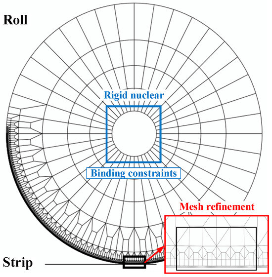
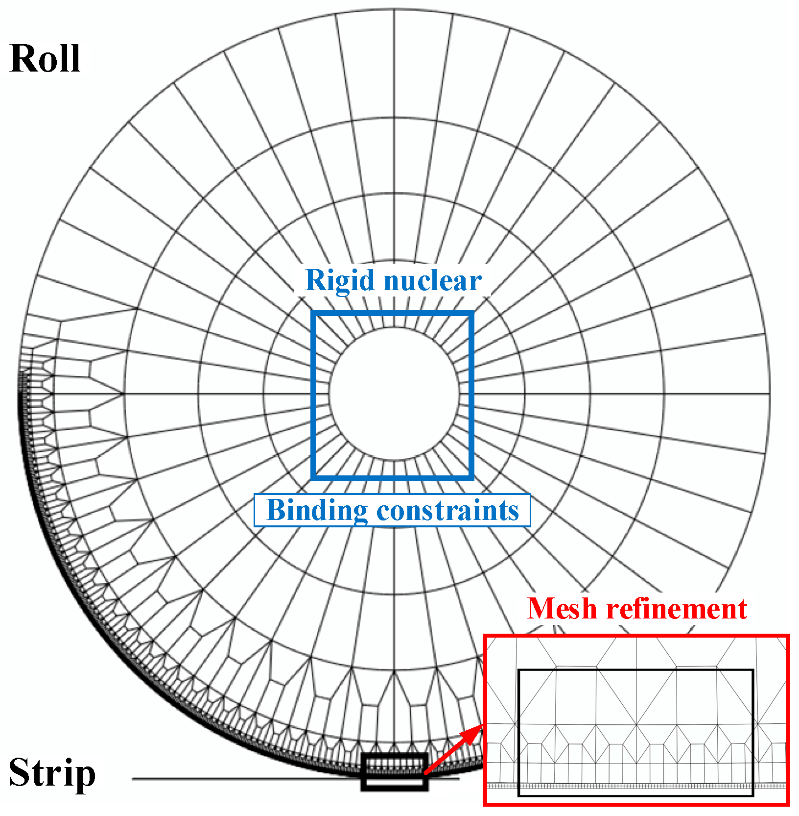
The thin strip rolling model was established in the ABAQUS software. Taking the assumption of the plane strain and the symmetry of the rolling process into account, a half-rolling model was conducted for FEM analysis, as shown in Figure 1. The roll is elastic, and the strip is an elastoplastic body adopted with CPE4R bilinear plane strain reduction integral elements. The strip is divided into four layers in the thickness direction. Due to not considering the bending effect of the roll, the model applies displacement and speed boundary conditions to the rolling mill by establishing a rigid core and binding constraint with the roll. The tensile stress is assumed to act consistently along the normal to the roll centerline, which is equivalent to neglecting the grip angle conventionally associated with the strip rolling process. This simplification is widely employed in analytical rolling models to render the boundary conditions more tractable. Nevertheless, it should be acknowledged that such an assumption may introduce non-negligible discrepancies under conditions involving significant geometrical nonlinearity, where the grip angle effect is no longer marginal. The Coulomb friction model is used for the contact surface, and the roll meshing is refined in the contact area to balance the solution efficiency and accuracy, and the size ratio of the mesh elements on the surface of the roll to the surface of the strip is 2~3. By partitioning the section of the rolling mill and editing sketches to achieve precise seeding, the target mesh refinement form can be obtained.
Figure 1.
Finite element model for ultra-thin strip rolling.
In the model, further reductions are obtained by applying displacement boundary conditions to the rolls. Due to the large elastic deformation of the roll and strip in the rolling process, the single-pass reduction is calculated by the actual thickness of the strip after rolling, and the target reduction is obtained by adjusting the displacement boundary conditions of the roll several times. In the initial state, the strip is positioned within the roll gap, signifying the completion of the threading process. Prior to the compression analysis step, a Y-direction displacement boundary condition is applied to the roll. Subsequently, for the rolling analysis step, rotational boundary conditions are imposed to simulate the roll speed, and the solution proceeds until a steady rolling state is achieved.
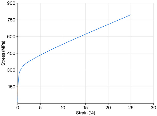
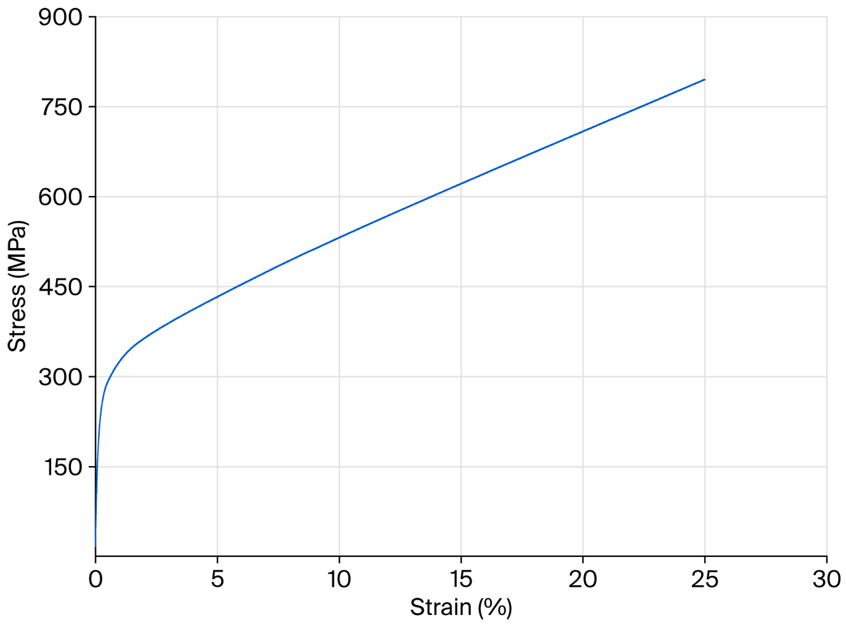
Given the calculation factors in Table 1, the corresponding Stone minimum rolling thickness can be calculated. The chemical composition and material properties of 304 stainless steel strip are shown in Table 2 and Figure 2.
Table 1.
The materials properties in the FEM analyses.
Table 2.
The chemical composition of 304 stainless steel strip.
Figure 2.
The material properties of 304 stainless steel strip.
To explore the generation conditions and variation patterns of the neutral zone in the contact deformation zone under different rolling conditions, select the initial thickness of the strip as 0.30 mm, 0.20 mm (larger than the ), 0.150 mm, 0.125 mm (approximately equal to the ), 0.10 mm, 0.075 mm and 0.05 mm (less than the ), and establish a finite element model to solve and calculate the rolling process. Considering the influence of initial thickness and single-pass deformation on the shape of the contact deformation zone, analyze the variation in the contact deformation zone during the thin strip rolling process under two different working conditions through finite element models:
- Focused on the thickness effect, given a fixed minimum single-pass reduction, analyze the initial thickness of the strip, gradually decreasing from larger than Stone the minimum rolling thickness to less than the Stone minimum rolling thickness.
- Focused on the reduction effect, the initial thickness of the strip is fixed and larger than the Stone minimum rolling thickness, while the single-pass reduction gradually increases.
1.2. Analysis of FEM Simulation Results
In the steady rolling state, the displacements along the thickness direction of the strip surface nodes in the contact deformation zone are extracted. The ratio of the actual strip thickness in the contact deformation zone to the initial thickness () is used to represent the strip profile in the contact deformation zone, that is, the roll shape profile in the contact deformation zone. Under different rolling conditions, the roll shape profile and the contact pressure distribution within the contact deformation zone were obtained.
1.2.1. The Same Reduction but Different Initial Thicknesses
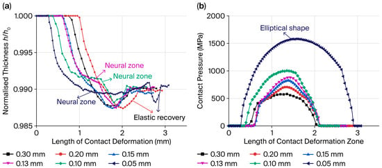
Figure 3 shows the contact deformation zone characteristics of strips with different thicknesses under 1% reduction, including roll shape profile and distribution of the contact pressure. The thickness of the strip gradually decreases from 0.15 mm (larger than ) to 0.10 mm (less than ), and the roll profile in the contact deformation zone changes from an arc shape to a non-circular arc shape, with a certain length of flat area appearing and becoming more obvious. The contact pressure distribution tends towards a parabolic distribution from an observable peak. For 0.05 mm, which is relatively small, even when the reduction is around 1%, the flat section area accounts for a considerable proportion, the plastic deformation zone length is minimal, and the contact pressure is approximately a parabolic distribution. From Figure 2, it can be seen that the calculation results of the roll profile and contact pressure distribution in the contact deformation zone obtained by the finite element model are consistent with the Fleck theory [30]. It should be noted that, in thin and ultra-thin strip rolling, the neutral point in conventional rolling theory expands into a neutral zone. The contact deformation zone comprises the inlet elastic zone, inlet plastic zone, neutral zone, outlet plastic zone, and outlet elastic zone. Plastic deformation of the strip is mainly concentrated at the inlet and outlet of the contact deformation zone, while no significant plastic deformation occurs in the neutral zone. Within this neutral zone, no relative sliding occurs between the roll and strip surfaces; the friction regime transitions from Coulomb friction to adhesive friction, and the strip thickness does not undergo appreciable change. The location and extent of the neutral zone therefore govern the friction force distribution, strip velocity profile, and rolling pressure along the roll gap, and serve as a useful indicator of deformation efficiency. This has been confirmed through experiments by Sutcliffe that the metal is in an elastic state in the neutral zone, with no significant change in thickness.
Figure 3.
Contact deformation zone characteristics of strips with different thicknesses under 1% reduction: (a) roll shape profile, (b) distribution of the contact pressure.
With the increase in reduction, the contact deformation zone of the thin ribbon with different thicknesses is no longer circular, the neutral zone is more apparent, and the contact pressure is similar to a parabolic distribution. The proportion of the neutral zone is more significant and larger, the rolling force increases sharply, and the plastic deformation of strip steel becomes more and more difficult.
To sum up, when the initial thickness of the strip is near the Stone minimum rolling thickness and the initial thickness of the strip decreases or the single-pass reduction increases gradually, the length of the contact deformation zone increases, the neutral zone becomes more and more obvious, and the contact pressure also increases sharply, which is close to the parabola distribution, quite different from the assumption that the roll still keeps circular shape after contact flattening in Stone contact deformation zone theory. Stone thinks that it can not be rolled when the initial thickness of the rolled piece is less than the calculated value of the Stone minimum rolling thickness. However, based on the above analysis, although the neutral zone in the contact deformation zone accounts for a large proportion, a certain amount of deformation can be obtained by increasing the rolling pressure, that is, the strip can be rolled.
1.2.2. The Same Initial Thickness but Different Reductions
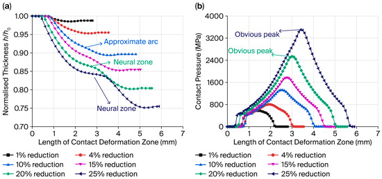
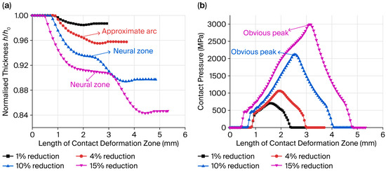
Figure 4 illustrates the contact deformation zone characteristics of the 0.30 mm-thick strip under different reductions, including the roll shape profile and the contact pressure distribution. Compared with Figure 2, the initial thickness of the strip increases further, and it can be seen that there is no neutral zone in the contact deformation zone at a 1% and 4% reduction. Protrusions begin to appear at a 10% reduction, while the neutral zone can be observed in the contact deformation zone when the reduction is 15% and 20%. As the reduction continues to increase, the contact deformation area increases correspondingly, the proportion of the neutral area increases, the elastic flattening deformation of the roll becomes more and more obvious, the peak value of contact pressure distribution increases sharply, and the distribution becomes slender.
Figure 4.
Contact deformation zone of the 0.30 mm-thick strip under different reductions: (a) roll shape profile, (b) distribution of the contact pressure.
Figure 5 shows the contact deformation zone characteristics of the 0.20 mm-thick strip under different reductions, including roll shape profile and distribution of the contact pressure. Compared with Figure 3, when the initial thickness of the strip decreases, the roll profile still keeps the arc shape at 1%. However, the circular arc roller shape begins to protrude at a 4% reduction. When the reduction is 10%, there is a neutral zone in the contact deformation zone. Then, with the increase in reduction, the length of the contact deformation zone increases, and the proportion of the neutral zone also increases. The variation law of contact pressure distribution is the same.
Figure 5.
Contact deformation zone of the 0.20 mm-thick strip under different reductions: (a) roll shape profile, (b) distribution of the contact pressure.
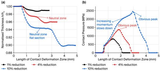
Figure 6 shows the contact deformation zone characteristics of the 0.15 mm-thick strip under different reductions, including roll shape profile and distribution of the contact pressure. The circular arc roller shape begins to protrude at a 4% reduction compared with the 4% in Figure 4. Different from Figure 3 and Figure 4, a clear neutral zone is present when the reduction increases is 4%. As the reduction increases from 1% to 10%, the contact deformation area increases correspondingly, and the proportion of the neutral zone increases. The elastic flattening deformation of the roll becomes more and more apparent, and the concave on the left side of the contact pressure peak increases to a convex shape, according to the maximum unit pressure distribution that the roll can provide.
Figure 6.
Contact deformation zone of the 0.15 mm-thick strip under different reductions: (a) roll shape profile, (b) distribution of the contact pressure.
1.2.3. Results of Rolling Force per Unit Width
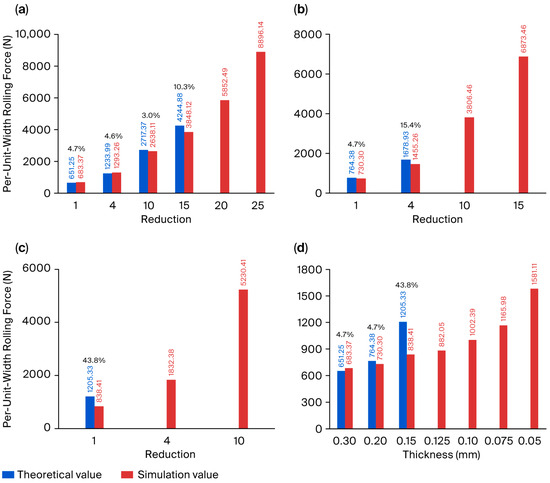
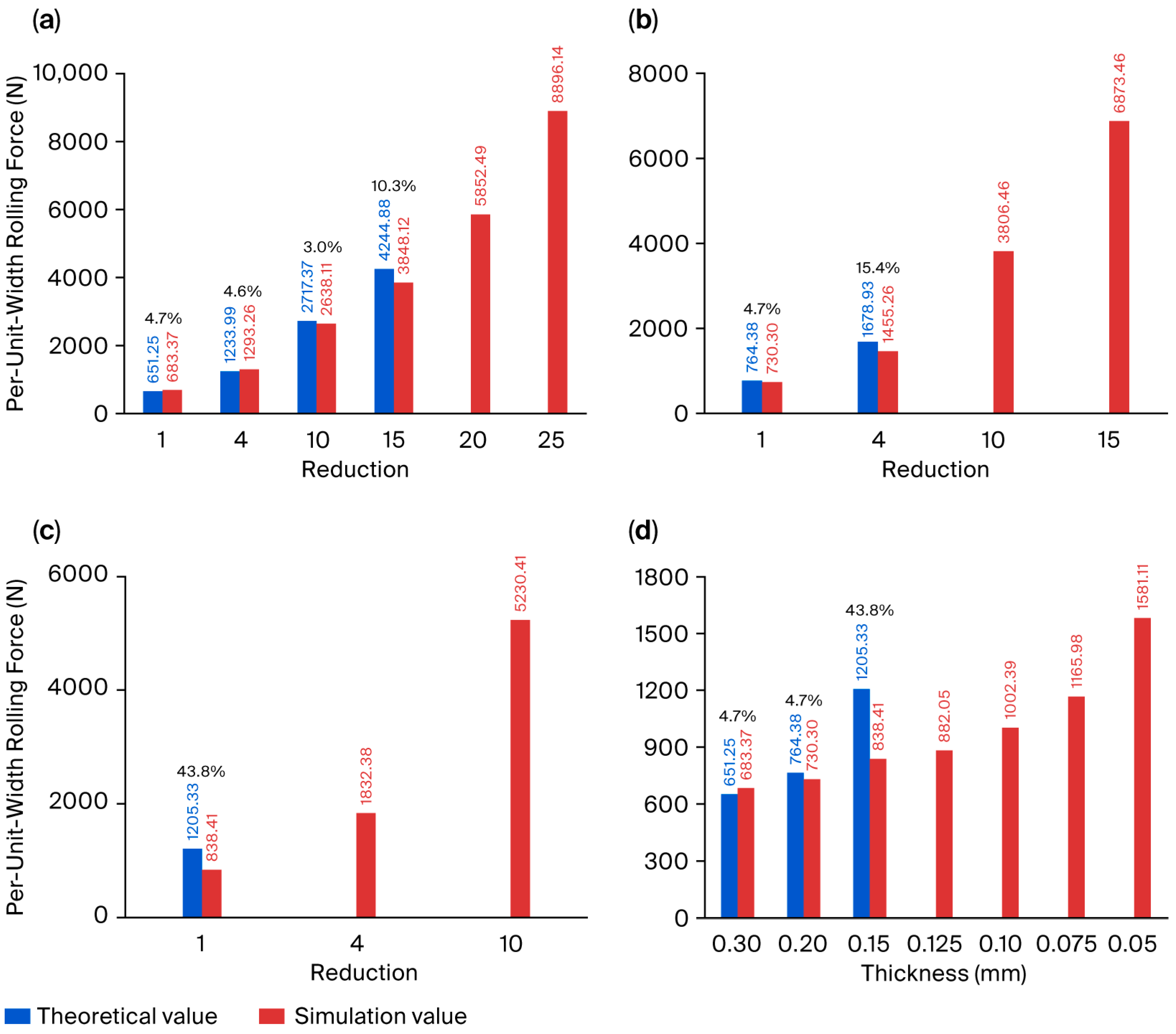
To sum up, as the initial thickness of the strip decreases, the critical reduction that occurs in the neutral zone within the contact deformation zone decreases, and the elastic flattening deformation of the roll becomes more and more obvious. The friction coefficient of 0.1 was adopted based on Refs. [22,25] for oil-lubricated thin-strip rolling, where an oil film effectively immerses the contact zone. The results show that, despite this relatively low friction coefficient, no slipping occurs between the rolls and the strip. This is attributed to the substantial elastic flattening of the rolls (Figure 1, Figure 2, Figure 3 and Figure 4a), which significantly enlarges the contact area and thus provides sufficient frictional traction, coupled with the fact that, unlike plate rolling, thin-strip rolling does not involve a biting-in process. The rolling condition factors of 0.15 mm, 0.2 mm, and 0.3 mm thick strips with different reductions were substituted into the Stone rolling force model to calculate the per-unit-width rolling force, and the contact pressure distribution was integrated into the corresponding finite element model to obtain the per-unit-width rolling force by the integral algorithm. As shown in Table 3 and Figure 7, the ‘-’ in the table indicates that there is no corresponding calculation value.
Table 3.
Calculation of rolling force per unit width.
Figure 7.
Rolling force per unit width under different thicknesses and deformation reductions. (a) 0.30 mm, (b) 0.20 mm, (c) 0.15 mm, (d) different thicknesses under 1% reduction.
For the thicknesses of 0.30 mm and 0.20 mm, when the single-pass reduction is 1%, the calculation of the Stone formula is close to the simulation result. The relative error is minimal, and the relative error increases with the increase in single-pass reduction. There are two reasons for the relative error. One is that the elastic deformation of the strip is not considered in the Stone rolling force model. The other is that the finite element simulation results are obtained under the approximate pass reduction. For the thickness of 0.15 mm, when the single-pass reduction is less than 1%, the calculated value of the Stone rolling force formula is quite different from the finite element simulation value. At this time, the actual profile of the roll in the contact deformation zone is not consistent with the assumption of an arc profile in the calculation condition. When the pass reduction is increased to 4%, the Stone rolling force formula cannot be calculated. Similarly, the Stone rolling force model is not applicable when the pass reduction is 10%. For the 0.3 mm thick strip, referring to Figure 4a, when the single-pass reduction increases to 15%, there is an obvious neutral zone in the contact deformation zone, while Stone thinks that the whole deformation zone is a plastic zone. The same applies to 0.20 mm under the condition of 10% reduction, referring to Figure 5a. The Hitchcock formula is used to calculate the length of the contact deformation zone and multiply the average unit pressure of the plastic zone to obtain the rolling force; however, this approach introduces significant error. The Stone rolling force formula cannot be used when the single-pass reduction exceeds a certain pass. In the theoretical analysis, it is assumed that the rolling mill stand is capable of supplying a sufficiently large rolling force per unit width and that the main drive motor can deliver an adequate rolling torque. Accordingly, the constraints imposed by the mill’s load and power capacity are not taken into consideration in the present model.
The Stone deformation-zone theory is widely recognized as possessing general applicability in the cold rolling of thin strips. However, as noted earlier, the original derivation of the Stone model rests upon the assumption that the entire deformation zone undergoes plastic deformation. When the strip thickness is relatively large, the elastic region within the contact deformation zone is negligibly small and can thus be safely disregarded, resulting in satisfactory accuracy of the analytical predictions. In terms of friction treatment, the numerical and analytical models share identical assumptions. Nevertheless, the numerical solution is obtained through an iterative matching procedure that enforces convergence between the deformed roll profile and the contact pressure distribution along the deformation zone. For relatively large strip thicknesses, the numerical accuracy is comparable to that of the analytical solution. As the strip thickness decreases progressively, however, a neutral zone emerges and expands within the contact deformation arc. Under such circumstances, the numerical approach exhibits a distinct advantage in terms of solution accuracy over its analytical counterpart.
Overall, when the strip thickness is larger than the calculated value of the Stone minimum rolling thickness, the hypothesis that the roll in the Stone contact deformation zone theory remains circular after contact flattening is valid within a certain range of the single-pass reduction, and the Stone rolling force model is applicable. It is worth noting that the larger the thickness of the strip, the larger the range of single-pass reduction applicable to the Stone rolling force model. As the single-pass reduction further increases, there is a clear neutral zone in the contact deformation zone, and the Stone rolling force model is not applicable, and other improved rolling force formulas based on the Stone formula are also not applicable. The presence of the neutral zone causes a sharp increase in rolling force, but the plastic deformation of the strip does not significantly increase, so the rolling efficiency is low.
2. Theory of the Limiting Producible Thickness
When the initial thickness of the strip is larger than the Stone minimum rolling thickness, the applicability of the Stone rolling force model depends on the single-pass reduction. Therefore, only by finding out the range of the single-pass reduction can it play an influential role in practical applications.
2.1. Analysis of the Contact Deformation Zone
The cold rolling process of the thin plate and the strip is approximately regarded as the compression between parallel plates, and the elastic deformation and plastic deformation of the rolled piece are relatively small and neglected. It is assumed that the friction on the contact surface conforms to Coulomb’s law of friction: there is no internal deformation of the metal, the direction of the principal stress does not change, and the friction coefficient does not change along the contact arc length. The problem is simplified as a plane-strain condition, wherein the effect of strip width is not taken into account. Consequently, the influence of roll deflection on the contact deformation zone along the width direction is also neglected.
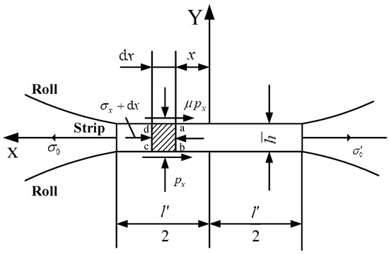
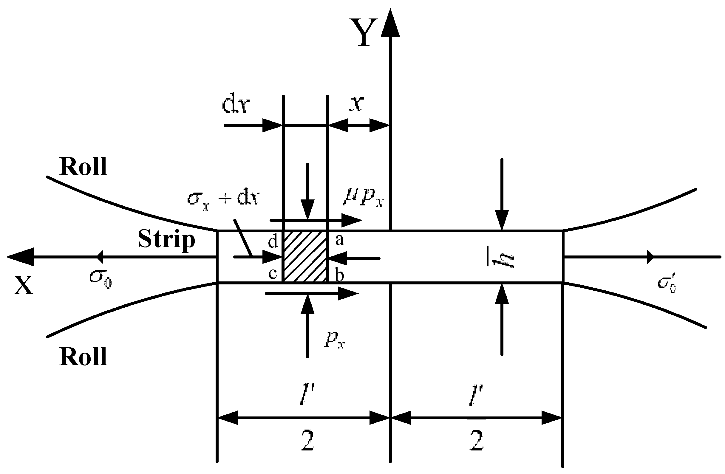
As shown in Figure 8, the average normal compressive stress on section a-b is represented by , the difference between section c-d and section a-b is , the average normal compressive stress on section a-b is represented by , there is unit frictional force acting on the upper and lower surfaces of the unit body and unit pressure , the total length of the contact deformation zone is , and the unit body a-b-c-d approximates the equilibrium differential equation.
where is the average thickness of rolled piece and .
Figure 8.
Force diagram of the unit body in the contact deformation zone.
In the figure, the positive X-axis represents the direction of reverse strip advancement, the positive Y-axis represents the direction of strip thickness, and the arrow represents the positive direction.
For the element body, the coordinate axis is approximately regarded as the principal direction and the Tresca plastic yield condition is used to obtain the following results.
If Equation (3) is integrated from to , the following expression is obtained.
where is the shear yield limit of rolled piece and is the mean tensile stress, that is, the average tensile stress at the entrance and exit.
The average unit pressure is
Equation (5) shows the value of the corresponding average unit pressure when the length of the contact deformation zone is , which is related to the thickness of the rolled piece, the properties of the metal material, the average tensile stress, and the friction coefficient.
From the Hitchcock formula of the contact arc length
where is the roll radius and is the single-pass deformation.
If
And multiply both sides of the equation by ,
Equation (8) shows the maximum average unit pressure that can be provided for the length of the contact deformation zone when abnormal deformation does not occur.
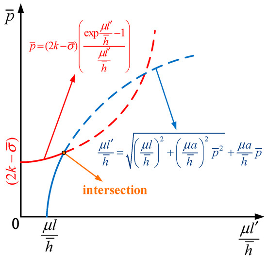
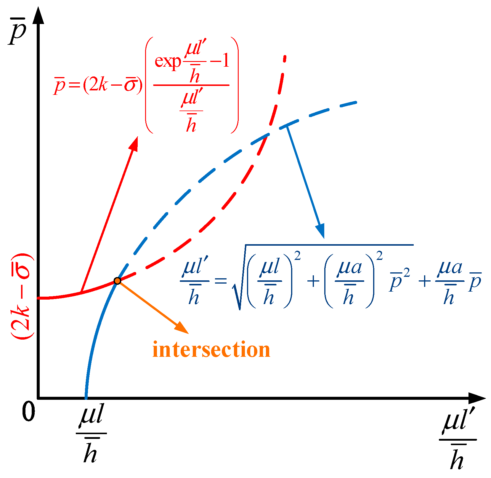
It can be seen that Equations (5) and (8) are related to each other and cannot be solved directly. The rectangular coordinate system is established for the horizontal axis of and the vertical axis of , and the corresponding relationship curves of Equations (5) and (8) are made respectively. The relationship between the two curves represents different rolling conditions, and the core of the Stone rolling force model is to solve two curves under different rolling conditions.
When the two curves are far apart, it indicates that the maximum average unit pressure provided by the roll cannot meet the average unit pressure conditions required to produce the length of the contact deformation zone. At this time, the rolling process cannot be established, that is, it cannot be rolled.
When the two curves intersect, the length of the contact deformation zone and the average unit pressure under this rolling condition can be obtained by solving for the intersection point, as shown in Figure 9. This method is relatively simple to solve. It is commonly used for the design and calculation of thin strip cold rolling processes and equipment.
Figure 9.
Schematic diagram of basic rolling condition.
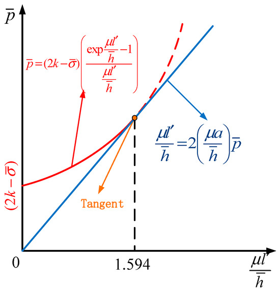
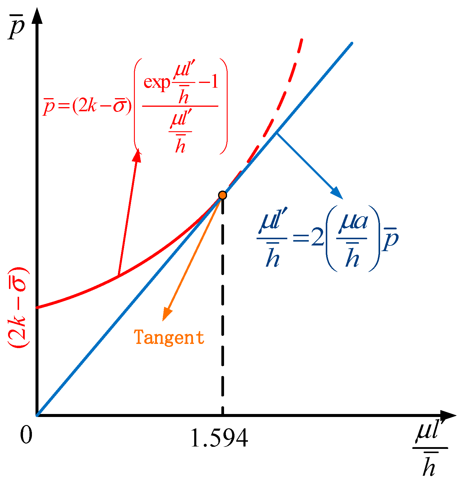
When the rolling conditions change and the two curves gradually approach, there is a critical condition where the two curves are tangent and the length curve of the contact deformation zone (which becomes a straight line at this time) intersects with the horizontal axis at 0, as shown in Figure 10. In other words, the maximum average unit pressure that the rolling roll can provide can precisely provide the average unit pressure condition required to meet the infinite length of the contact deformation zone approaching zero. Continuing to approach, the two curves intersect, reaching normal rolling conditions.
Figure 10.
Schematic diagram of the condition of the Stone minimum rolling thickness.
If the intersection point between the contact arc length curve and the transverse axis is exactly zero, the maximum average unit pressure provided by the roll can just provide the average unit pressure condition required to make the metal produce plastic deformation, that is, the derivation conditions of the Stone minimum thickness formula.
The slope at the intersection is the same, where .
Derive Equation (5) and Substitute it into Equation (9), it can be obtained
Simplify Equation (10) to obtain
By solving Equation (11), it can be concluded that
Substituting Equation (12) into Equation (10), the critical slope can be obtained as follows:
From Equation (8), it can be concluded that
The above equation is further reduced to
Equation (15) expresses Stone’s minimum rolling thickness consistent with Equation (1). It can be seen that the minimum rolling thickness during the rolling process is related to the roll diameter, roll elastic modulus, friction coefficient, yield limit of the rolled piece, and average tensile stress. Whether it is a numerical simulation, experiment, or actual production, the Stone minimum rolling thickness is not the true limit rolling thickness. However, based on the simulation results discussed in Section 1.2, this value can be regarded as the critical thickness of the neutral zone within the contact deformation zone under the condition of minimum single-pass reduction. When the thickness of the rolled piece exceeds this critical value, the roll maintains a circular arc profile in the contact deformation zone. Conversely, when the thickness falls below this value, an obvious neutral zone emerges in the contact deformation zone, and the roll exhibits a non-arc profile. As noted earlier, the presence of the neutral zone in the contact deformation zone consumes rolling pressure without contributing to plastic deformation of the metal, thereby reducing rolling efficiency.
2.2. Theory of the Limiting Producible Thickness Considering Deformation Efficiency
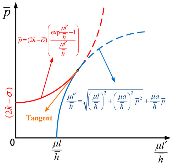
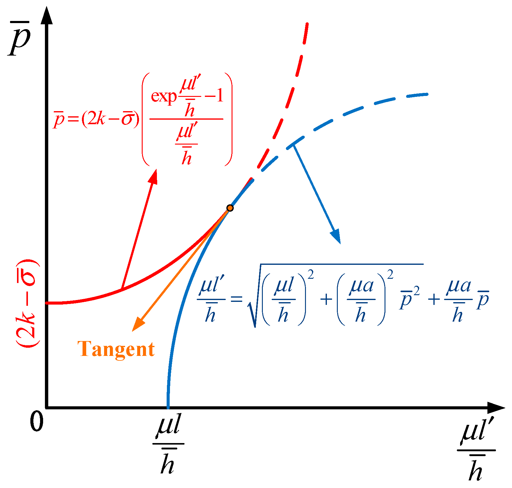
When the rolling conditions change, there is still a special case where the corresponding relationship between Equations (5) and (8) are critical conditions of tangency, as shown in Figure 11. That is to say, the maximum average unit pressure provided by the roll can just provide the average unit pressure condition required to meet the length of the contact deformation zone. If the two curves continue to approach and intersect, rolling can proceed normally.
Figure 11.
Schematic diagram of critical rolling condition.
It can be obtained from Equation (5) that
where in the length of the deformation zone .
From Equation (8), it is concluded that
From the fact that the function value and derivative value at the tangent point of two curves are equal in Figure 7, the following equations can be obtained.
By adding and simplifying Equations (18) and (19), it is obtained that
Similarly, by subtracting Equation (17) from Equation (18) and simplifying, it is obtained that
Based on the derivation process of Stone’s minimum rolling thickness, if the intersection point between the contact arc length curve and the transverse axis is not zero, that is, the critical rolling condition when the maximum average unit pressure provided by the roll can make the rolled piece produce the maximum reduction. By substituting Equation (18) into Equation (14), it can be obtained that
From the formula of the contact arc length of the arc , it can be obtained that
where represents the single-pass reduction.
Equation (20) can be rewritten as
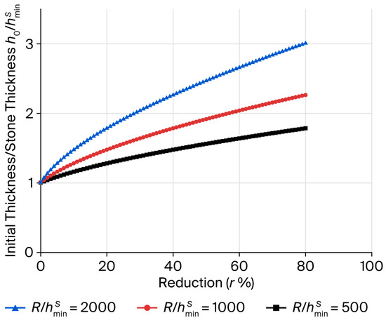
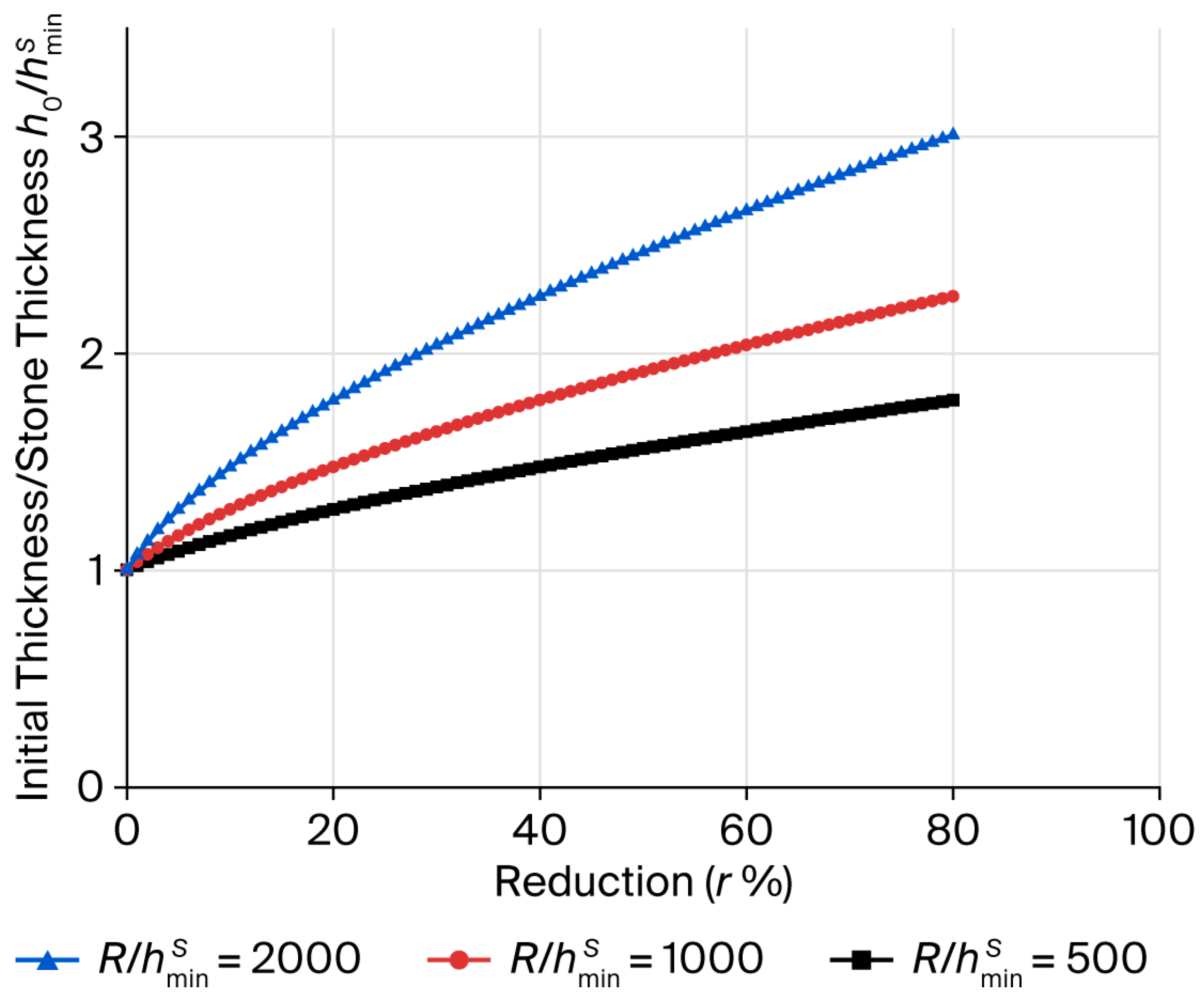
Given the rolling technical factors, the value of the contact arc length can be obtained for a certain reduction in the substitution Equation (24), and the ratio between the corresponding initial thickness and the Stone minimum rolling thickness can be obtained from Equation (22). Take the friction coefficient as 0.1, when the values are different, establish the rectangular coordinate system as the horizontal axis and the vertical axis, and the curve as shown in Figure 11 can be obtained.
Figure 12 shows the corresponding relationship curve between and when the values are different. For a given rolling process parameter and value, when known, a reduction can be found on the curve at this reduction, there is no neutral zone in the contact deformation zone of the strip rolling process, that is, there is a critical reduction for the initial thickness of the strip without the neutral zone, which can also be understood as the minimum rolling thickness under a certain single-pass reduction. The intersection of the curve and the longitudinal axis is 1, which means that for a minimum single-pass reduction when the initial thickness of the strip is larger than or equal to the value, there is no neutral zone in the contact deformation zone. The slope of the curve decreases with the increase in the abscissa, indicating that the closer the initial thickness of the strip is to the value, the more sensitive it is to the change in the single-pass reduction, and the larger the value is, the larger the critical single-pass reduction is.
Figure 12.
Corresponding relationship curve with different values.
3. Results and Discussions
The theoretical derivation of the critical pass deformation rate formula covers all operating conditions of the Stone formula, including the relative positional relationship between the two curves. Considering the solution of critical conditions, there is no obvious neutral zone in the contact deformation zone, which means that the Hitchcock formula can still be used to solve the contact arc length, assuming that the contact profile is a circular arc with an increasing radius. The assumption of a circular arc profile is valid.
To fully describe the corresponding relationship between the ratio of the initial thickness of the strip to the calculated value of the Stone minimum rolling thickness and the critical single-pass reduction under different rolling process factors, substituting Equation (7) into Equation (24) to simplify and carry out the dimensionless treatment.
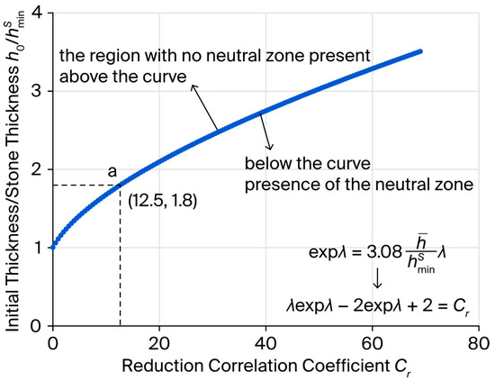
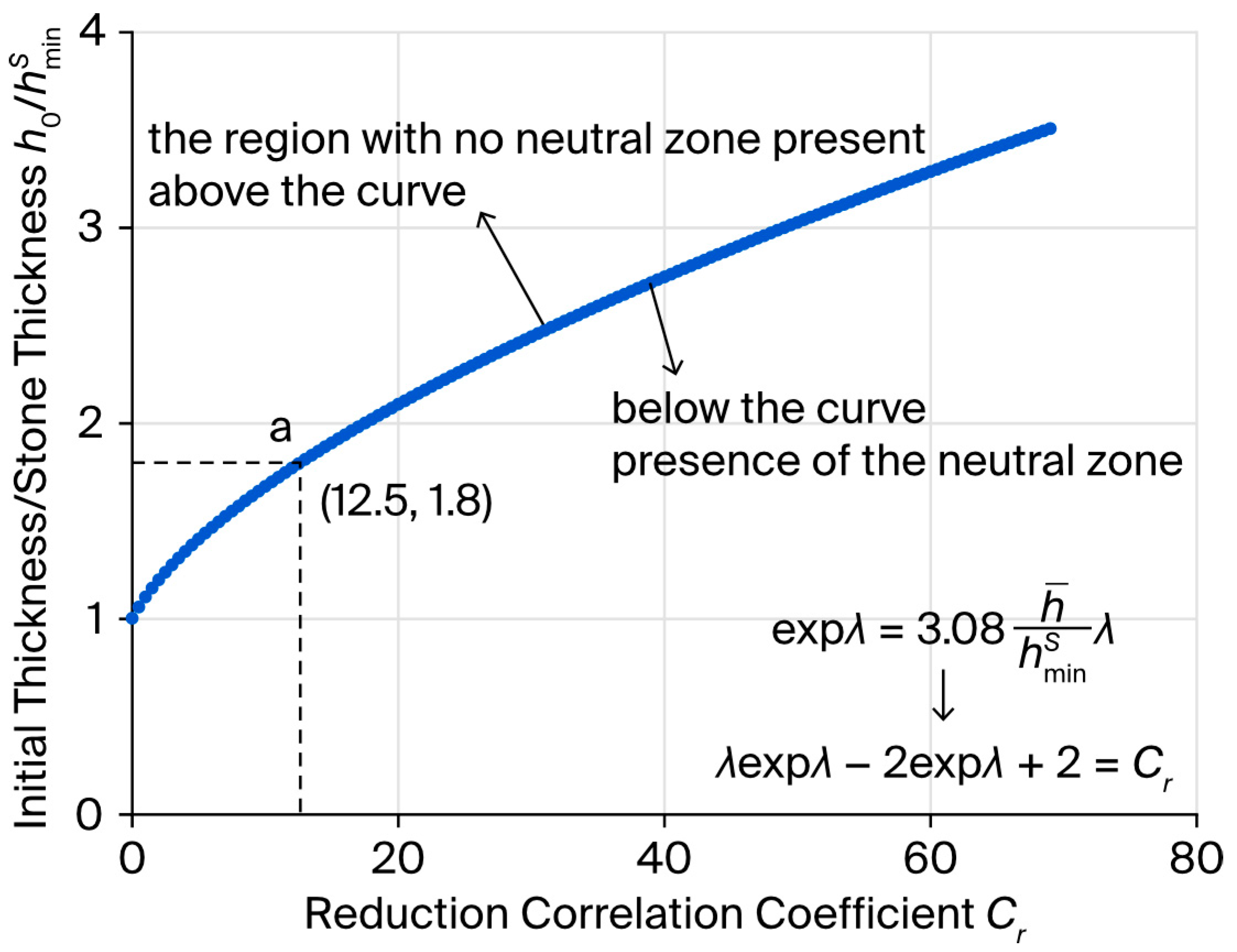
If the is defined as the RCC (reduction correlation coefficient), the expression can be obtained. It can be expressed as follows:
It should be noted that, in practice, the h/R ratio is often employed as an intuitive measure of rolling difficulty. In the proposed model, however, this geometric factor is considered alongside yield strength and mean tension stress, yielding a comprehensive indicator that better captures the overall rolling conditions.
Taking the RCC (reduction correlation coefficient) as the horizontal axis and the ratio of the initial thickness to the calculated value of the Stone minimum thickness formula as the vertical axis, the rectangular coordinate system is established, and the curve shown in Figure 12 can be obtained.
The curve in Figure 13 shows the critical rolling condition of the Stone theory of the contact deformation zone, which applies to any rolling process factor. The area above the curve indicates the rolling condition that there is no neutral zone in the contact deformation zone, and the assumption of the roll arc profile is valid. In this area, the Stone rolling force model is applicable, and the rolling efficiency is high. In a certain range below the curve, the strip can still be rolled, and there is a neutral zone with a certain proportion of length in the contact deformation zone, and part of the rolling force keeps the metal elastic deformation in the neutral zone. The rolling efficiency is relatively low.
Figure 13.
Critical conditions for the existence of neutral zone in contact deformation zone.
Taking the laboratory 2-high rolling mill as an example, the rolling process parameters are known: roll diameter 210 mm, elastic modulus 216 GPa, Poisson’s ratio 0.3, friction coefficient 0.1. If the yield strength of low carbon steel strip is 235 MPa, the Stone minimum rolling thickness can be calculated as follows:
When the initial thickness of the strip is 1.8 times of that of point ‘a’ in Figure 12, the corresponding reduction correlation coefficient is 12.5.
When the work hardening behavior of the metal strip is neglected, analysis indicates that the critical single-pass reduction required to avoid the formation of a neutral zone is 36.3%. This implies that if the applied reduction exceeds this threshold, a neutral zone will inevitably develop within the contact deformation zone, leading to a significant decline in rolling efficiency due to redundant deformation and non-uniform strain distribution. For any given combination of rolling process parameters, the critical single-pass reduction can be quantitatively determined using the aforementioned methodology, which in turn allows for a clear evaluation of the deformation efficiency under specific rolling conditions. Furthermore, this approach enables the reverse determination of the feasible range of limiting producible thickness corresponding to a predefined reduction. These analytical outcomes provide valuable theoretical guidance for the rational design and systematic optimization of industrial rolling schedules, contributing to enhanced process stability and product quality in thin-strip rolling operations.
It is important to note that the limiting producible thickness model proposed in this study, which incorporates deformation efficiency, is derived based on the classical Stone theory for cold rolling of thin strips. A fundamental simplification in this theoretical framework is the neglect of work hardening effects that occur during the single-pass rolling deformation of the metal strip. Consequently, the critical single-pass reduction calculated using the present model is expected to be somewhat larger than the actual value observed in practice, where strain hardening inevitably increases deformation resistance. However, this overestimation does not significantly impair the practical utility of the model, as the predicted critical reduction remains a valuable reference for process design. In industrial thin-strip cold rolling applications, single-pass reductions are typically controlled within a range of up to 50%—well below the extreme reductions where the deviation would become operationally relevant. Thus, while the model provides a theoretically simplified representation, it still offers robust guidance for scheduling feasible reductions and predicting productivity limits within conventional processing windows. The results can be effectively used to optimize pass schedules and minimize the presence of inefficient neutral zones, thereby enhancing overall rolling efficiency and strip quality. It should be noted that the minimal producible thickness is not an absolute physical limit but rather a process-dependent threshold. Annealing treatment can effectively reduce the minimum producible thickness by decreasing the yield strength and deformation resistance of the strip material. According to Equations (1), (25) and (26), the minimum attainable thickness is proportional to the yield strength; thus, a fully annealed strip with lower yield strength allows for further thickness reduction beyond the limit achievable with work-hardened strip. The effectiveness of annealing in overcoming the thickness limit depends on the annealing parameters (temperature, holding time, cooling rate) and the specific material composition, which can be optimized in practice to extend the producible thickness range.
In summary, the rolling process for thin and ultra-thin strips can be accurately modeled and solved within a systematic theoretical framework that offers clear guidance for selecting the appropriate contact deformation zone theory and rolling force model based on specific process conditions. When the initial strip thickness exceeds the Stone minimum rolling thickness and the single-pass reduction remains below a critical threshold, the classical Stone rolling force model provides a reliable solution, as the deformation zone characteristics—particularly the well-defined arc-like roll profile and the absence of a significant neutral zone—are consistent with its fundamental assumptions. Conversely, when the initial thickness falls below the Stone minimum and the single-pass reduction exceeds the critical value, the producible rolling thickness model should be adopted. Under such conditions, the deformation behavior deviates markedly from the Stone assumptions, typically exhibiting a pronounced neutral zone and a non-arc roll profile, which the producible rolling thickness model is specifically designed to address.
4. Conclusions
- (1)
- The neutral zone is identified as an elastic region within the contact defor-mation zone where rolling pressure is dissipated without contributing to plas-tic deformation. A de-crease in initial strip thickness or an increase in reduction per pass tends to enlarge this zone, leading to a pronounced rise in rolling force accompanied by only marginal im-provement in elongation. The presence of such a neutral zone is inherently inconsistent with the fundamental assump-tions of the Stone rolling force model. However, the Stone minimum rolling thickness formula acquires a new physical interpretation: it represents the crit-ical thickness below which the neutral zone vanishes within the deformation zone under conditions of extremely small reduction. This reinterpretation re-solves a long-standing ambiguity in the classical theory and provides a more physically mean-ingful criterion for model selection.
- (2)
- When the initial strip thickness exceeds the Stone minimum rolling thickness under minimal single-pass reduction, the roll maintains an arc-shaped profile within the de-formation zone, validating the Stone model’s applicability. Conversely, when a pronounced neutral zone emerges with a non-arc roll pro-file—a condition typically encountered when the initial thickness falls below the Stone minimum or the reduction exceeds a critical threshold—the producible rolling thickness model must be applied for accurate analysis. This bifurcation in model applicability, determined by the neutral zone status, constitutes a key contribution of this work to the theoretical foundation of thin-strip rolling. The applicability of the Stone model also indicates that the rolling process is relatively efficient.
- (3)
- For any specified initial strip thickness and set of rolling parameters, there exists a critical single-pass reduction at which the neutral zone is precisely eliminated. A characteristic curve delineating these critical conditions has been constructed (Figure 13). The domain above this curve corresponds to rolling conditions without a neutral zone, where the cir-cular roll arc assumption holds and the Stone model remains valid with high deformation efficiency. Below the curve, rolling remains feasible within a certain range, albeit with a fi-nite neutral zone occupying part of the contact arc, where a portion of the rolling force is consumed in sustaining elastic deformation without thickness reduction. This character-istic curve thus serves as a practical tool for rolling schedule design, enabling operators to identify efficient operating windows and avoid unnecessary energy dissipation. The pro-posed framework is material-independent and applicable to various metallic materials given the corresponding property inputs, offering practical guidance for rolling force pre-diction, thickness control, and schedule optimization in industrial production.
Author Contributions
Conceptualization, J.J. and T.W.; Methodology, H.X.; Software, X.L. and L.X.; Formal Analysis, Z.R.; Investigation, X.L.; Resources, H.X. and Z.R.; Data Curation, L.X. and H.X.; Writing—Original Draft Preparation, X.L., L.X. and H.X.; Writing—Review & Editing, Z.R., T.W. and J.J.; Visualization, L.X.; Supervision, J.J.; Project Administration, J.J.; Funding Acquisition, J.J. All authors have read and agreed to the published version of the manuscript.
Funding
The authors gratefully acknowledge the support of the National Key R&D Program of China: 2025YFF0513700; Open Research Fund from State Key Laboratory of Metal Forming Technology and Heavy Equipment: S2308100.W01; Key Research and Development Program of Shanxi Province: 202202050201017 and National Natural Science Foundation of China: 52275361.
Data Availability Statement
The original contributions presented in this study are included in the article. Further inquiries can be directed to the corresponding author.
Conflicts of Interest
Authors Lipu Xu and Jiang Ji were employed by the company China National Heavy Machinery Research Institute Co., Ltd. The remaining authors declare that the research was conducted in the absence of any commercial or financial relationships that could be construed as a potential conflict of interest.
Abbreviations
The following abbreviations are used in this manuscript:
| Stone minimum thickness | |
| D | roll diameter |
| μ | Coulomb friction coefficient at the entrance of deformation zone |
| σs | yield strength of the strip |
| σT | mean tension stress |
| E | elastic modulus of the roll |
| h− | average thickness of the rolled piece |
| h0 | initial thickness of the rolled piece |
| h1 | outlet thickness of the rolled piece |
| k | shear yield limit of the rolled piece |
| σ− | mean tensile stress |
| p− | average unit pressure |
| l′ | length of the contact deformation zone |
| R | roll radius |
| Δh | single-pass deformation |
| ν | Poisson’s ratio of the roll |
References
- Ren, Z.; Guo, X.; Fan, W.; Wang, T.; Xiong, X. Research progress and prospects of precision ultra-thin strip rolling theory. J. Mech. Eng. 2020, 56, 73–84. [Google Scholar] [CrossRef] [Scilit]
- Liang, B.; Li, Y.; Han, P.; Zhu, X. Experimental and theoretical investigations on Si content induced rolling deformation uniformity and martensitic transformation for 301 stainless steel ultra-thin strip. J. Mater. Res. Technol. 2026, 42, 11261–11268. [Google Scholar] [CrossRef] [Scilit]
- Yang, L.; Zhang, H.; Zhang, Y. Present analysis and trend prediction of shape/performance collaborative control for high-end cold rolling foils. Acta Metall. Sin. 2021, 57, 295–308. [Google Scholar] [CrossRef] [Scilit]
- Wang, E.; Bian, L.; Zhao, Y.; Ping, H.; Wang, T.; Ren, Z.; Jiang, S.; Huang, Q. Effects of negative roll gap rolling and pulsed current annealing on microstructure and properties of Invar 36 alloy thin strip. J. Mater. Res. Technol. 2025, 36, 5583–5597. [Google Scholar] [CrossRef] [Scilit]
- Chen, S.; Yang, X.; Liu, G.; Wang, B.; Wang, B.; Tian, Y. Revealing the role of warm rolling on homogenized microstructure and enhanced properties for Inconel718 ultra-thin strip preparation. Mater. Sci. Eng. A 2025, 946, 149104. [Google Scholar] [CrossRef] [Scilit]
- Yuan, C.; Guo, Y.; Ma, J.; Han, Z.; Cheng, F.; Gao, L.; Yang, S.; Li, J.; Wang, Y. Effect of rolling deformation on the thermal expansion properties of ultra-thin Kovar alloy foils. J. Alloys Compd. 2026, 1052, 186081. [Google Scholar] [CrossRef] [Scilit]
- Karman, T.V. On the theory of rolling. Z. Für Angew. Math. Und Mech. 1925, 5, 139–141. [Google Scholar]
- Orowan, E.; Ing, D. The calculation of roll pressure in hot and cold flat rolling. Proc. Inst. Mech. Eng. 1943, 150, 140–167. [Google Scholar] [CrossRef] [Scilit]
- Ford, H.; Ellis, F.; Bland, D.R. Cold rolling with strip tension. Part II F. Iron Steel Inst. 1952, 171, 239–245. [Google Scholar]
- Hill, R. The Mathematical Theory of Plasticity; Oxford University Press: Oxford, UK, 1998; pp. 188–206. [Google Scholar]
- Stone, M.D. Rolling of thin strip Part II. Iron Steel Eng. 1956, 33, 55–76. [Google Scholar]
- Lian, J. Calculation of rolling pressure and ultimate minimum thickness for cold rolled thin plate I. Heavy Mach. 1979, 2, 20–37. [Google Scholar]
- Lian, J. Calculation of rolling pressure and ultimate minimum thickness for cold rolled thin Plate II. Heavy Mach. 1979, 3, 21–34. [Google Scholar]
- Hu, X. Determination of contact arc length and rolling force calculation considering elastic deformation at the inlet and outlet of cold rolled sheet metal. J. Northeast Heavy Mach. Coll. 1982, 1, 1–11. [Google Scholar]
- Han, G.; Li, H.; Liu, Y.; Zhang, J.; Yan, D.; Zhao, J.; Yang, Q.; You, X.; Hu, Z.; Liu, L. Method to accurately calculate rolling force of cold-rolled thin-hard strip with improvement for elastic flattening of work roll. Appl. Math. Model. 2027, 162, 117202. [Google Scholar] [CrossRef] [Scilit]
- Qu, F.; Han, Y.; Yang, M.; Xu, J.; Aljabri, A.; Zhang, J.; Jiang, Z. Exploration of thermal phenomenon and its effect on Taguchi parametric optimisation in micro flexible rolling of thin steel strips. Eng. Comput. 2025, 42, 3394–3426. [Google Scholar] [CrossRef] [Scilit]
- Hitchcock, J.H. Roll Neck Bearings; American Society of Mechanical Engineers: New York, NY, USA, 1935; pp. 33–41. [Google Scholar]
- Pawelski, O.; Kading, G. Causes of the limiting degree of deformations in the cold rolling of thin strip. Arch. Eisenhuttenwes. 1970, 41, 249–254. [Google Scholar]
- Wu, S.; Zhou, L. Research of smallest permissive-rolling thickness during strip rolling. China Metall. 2007, 17, 10–12. [Google Scholar]
- Zhu, Q.; Yu, J.; Qi, K. Problem of reducibility in sheet cold-rolling and gauge suitable to roll. J. Northeast Univ. Technol. 1988, 9, 420–426. [Google Scholar]
- Johnson, K.L.; Bentall, R.H. The onset of yield in the cold rolling of thin strip. J. Mech. Phys. Solids 1969, 17, 253–264. [Google Scholar] [CrossRef] [Scilit]
- Fleck, N.A.; Johnson, K.L. Towards a new theory of cold rolling thin foil. Int. J. Mech. Sci. 1987, 29, 507–524. [Google Scholar] [CrossRef] [Scilit]
- Fleck, N.A.; Johnson, K.L.; Mear, M.E.; Zhang, L.C. Cold rolling of foil. Proc. Inst. Mech. Eng. Part B J. Eng. Manuf. 1992, 206, 119–131. [Google Scholar] [CrossRef] [Scilit]
- Le, H.R.; Sutcliffe, M.P.F. A robust model for rolling of thin strip and foil. Int. J. Mech. Sci. 2001, 43, 1405–1419. [Google Scholar] [CrossRef] [Scilit]
- Langlands, T.; Mcelwain, D.; Domanti, S.A. An approximate method for the solution of an influence function foil rolling model. Int. J. Mech. Sci. 2004, 46, 1139–1156. [Google Scholar] [CrossRef] [Scilit]
- Ren, Z.; Wang, T.; Wang, Y.; Fan, W.; Fu, W.; Guo, X. Analysis of contact contour and contact pressure in deformation zone of ultra-thin strip rolling. Iron Steel 2018, 53, 62–68. [Google Scholar]
- Xiao, H.; Liu, X. Theory and numerical simulation of gauge suitable to roll in ultra-thin strip rolling. Iron Steel 2019, 54, 48–55. [Google Scholar]
- Liu, X.; Xiao, H. Theoretical and experimental study on the producible rolling thickness in ultra-thin strip rolling. J. Mater. Process. Technol. 2020, 278, 116537. [Google Scholar] [CrossRef] [Scilit]
- Xiao, H.; Ren, Z.; Liu, X. New mechanism describing the limiting producible thickness in ultra-thin strip rolling. Int. J. Mech. Sci. 2017, 133, 788–793. [Google Scholar] [CrossRef] [Scilit]
- Sutcliffe, M.P.F.; Rayner, P.J. Experimental measurements of load and strip profile in thin strip rolling. Int. J. Mech. Sci. 1998, 40, 887–899. [Google Scholar] [CrossRef] [Scilit]

Disclaimer/Publisher’s Note: The statements, opinions and data contained in all publications are solely those of the individual author(s) and contributor(s) and not of MDPI and/or the editor(s). MDPI and/or the editor(s) disclaim responsibility for any injury to people or property resulting from any ideas, methods, instructions or products referred to in the content. |
© 2026 by the authors. Licensee MDPI, Basel, Switzerland. This article is an open access article distributed under the terms and conditions of the Creative Commons Attribution (CC BY) license.