


Abstract
Lump ore reduction generates fines that can induce furnace hanging or slipping. Reducing this degradation is key to maintaining stable operation. To address the degradation problem of lump ores during direct reduction in hydrogen-based shaft furnaces, this study systematically investigated the effects of reduction temperature and reduction time on the degradation behavior of three lump ores with distinct crystal structures under HYL atmosphere. The phase evolution, thermal decomposition characteristics and microstructural damage mechanisms during reduction were elucidated. The results showed that all three lump ores exhibited the most severe degradation after 60 min of reduction at 700 °C, with reduction degradation index values below 3.15 mm (RDI−3.15mm) of 32.50%, 15.17%, and 22.42% for Lump Ore 1, Lump Ore 2, and Lump Ore 3, respectively. During isothermal reduction at 500 °C, pronounced degradation occurred in all three ores at around 20 min (RDI−3.15mm: 33.09%, 18.09%, and 8.85% for Lump Ore 1, Lump Ore 2, and Lump Ore 3, respectively). Microscopic mechanism analysis revealed that dehydration of lump ores with high crystal water content caused structural damage, which was coupled with phase transformation stresses during reduction and led to severe degradation. In porous lump ore, stress was more readily dissipated and crack propagation was effectively buffered. In contrast, dense lump ore was prone to stress accumulation caused by locally nonuniform reduction, ultimately resulting in penetrating cracks. This study clarifies the degradation behavior of the three lump ores under different reduction regimes and reveals the evolution of phases and microstructures during reduction, providing a theoretical basis for stable operation of hydrogen-based shaft furnaces.
1. Introduction
China produced 960 million tons of crude steel in 2025, 4.4% less than in 2024, but remained the world’s largest producer and consumer of steel. The Chinese steel industry accounts for more than 60% of global steel sector CO2 emissions and over 15% of the country’s total industrial emissions, making it the largest carbon emitting manufacturing sector in China [1]. The conventional “blast furnace–basic oxygen furnace” (BF-BOF) long process, which relies primarily on fossil energy sources such as coke, represents the principal barrier to industrial low-carbon transformation and achieving the “dual-carbon” goals [2]. The development of green ironmaking routes has become an inevitable trend for the global steel industry [3]. Among these, gas-based shaft furnace direct reduction processes using hydrogen as the main reductant, such as MIDREX, HYL and ENERGIRON, are increasingly regarded as core technologies for low-carbon transformation owing to their considerable emission-reduction potential [4,5]. Several Chinese enterprises have already attempted to implement hydrogen-based direct reduced iron processes, including the 10,000 ton-class pure hydrogen shaft furnace demonstration project at the Hydrogen Metallurgy Center of China Iron & Steel Research Institute Group, the 300,000 t/a hydrogen-based shaft furnace demonstration project of Zhongjin Metallurgy using coke oven gas as the reducing gas, and the 600,000 t/a hydrogen-based shaft furnace reduction demonstration project of HBIS based on zero reforming of coke oven gas. In particular, Baowu Zhanjiang’s 1,000,000 t/a hydrogen-based shaft furnace adopts the HYL/ENERGIRON direct reduction technology that can use various gas sources, including coke oven gas, natural gas and gas with a high hydrogen fraction to produce high-quality direct reduced iron. Compared with the product of the existing blast furnace ironmaking at Zhanjiang Steel, the CO2 emissions can be reduced by 58–89% [6,7,8,9].
Optimization of the burden structure plays a crucial role in reducing cost, energy consumption, and emissions [10]. Oxide pellets and lump ores are currently the principal ferrous feeds for hydrogen-based direct reduction shaft furnaces [11]. Compared with lump ore, pellets require agglomeration and induration, which means higher capital investment, operating cost, and environmental burden. Increasing the proportion of lump ore in the burden can therefore provide both economic and environmental benefits [12,13].
Natural lump ore undergoes severe degradation during reduction, which is typically accompanied by the generation of a large amount of fine particles that deteriorate the gas permeability and may even induce hanging or slipping inside the furnace [14]. Several mechanisms have been proposed to explain reduction degradation: (1) Crystal structure transformation: hematite is sequentially reduced to magnetite, wüstite, and metallic iron. The reduction reactions by H2 can be expressed as follows:
In CO atmosphere, the corresponding reactions are:
These stepwise transformations involve crystal structure reconstruction and volume changes, generating internal stress that promotes particle cracking and disintegration [15,16]. (2) Iron whisker growth: induced by impurities or lattice defects, metallic iron grows anisotropically in a whisker-like form on the wüstite surface, displacing the surrounding grains and leading to catastrophic structural cracking [17]. (3) Internal stress: diffusion-limited differences in the reduction rate between the outer and inner layers of the ore generate non-uniform reduction, which induces plastic deformation and fracture [18,19,20]. (4) Carbon deposition: low temperature reduction is accompanied by a carbon-deposition reaction, and the deposited carbon accumulates within pores or crystals and thereby promotes cracking [21,22]. In addition, Ma et al. showed that reduction degradation arose from the coupled effects of mineralogy, gas transport, pore structure, and phase transformation stresses [23]. The transformation of hematite to magnetite generates lattice strain. When neighboring regions are reduced at different rates, local stress concentrates and cracks propagate [24]. Zakeri et al. reported that impurity phases and local chemical variations modified the reduction pathway and altered the morphology of the reaction front [25]. In ores rich in goethite, dehydroxylation occurs during heating according to the following reaction:
This produces pores and microcracks and reduces the strength of the ore matrix [26,27]. The crystalline water content alone is not sufficient to predict degradation susceptibility. The initial compactness, pore connectivity, phase distribution, and spatial uniformity of reduction must also be considered [28]. Comparative experiments on lump ore, sinter, and pellets in atmospheres containing hydrogen confirm that differences in mineralogy and internal structure produce distinct cracking patterns and degradation responses [14,29]. Taken together, these mechanisms indicate that reduction degradation is fundamentally driven by the generation, accumulation, and release of stress during reduction. The volumetric expansion caused by phase transformation of iron oxides is the fundamental source of stress. Reduction conditions and mineralogical characteristics modulate gas transport and stress accommodation, intensifying differences in reduction rate and producing different degradation behaviors.
Despite these advances, systematic comparisons of lump ores with different mineralogical characteristics under hydrogen-based shaft furnace conditions remain limited. In particular, the links among the phase transformation sequence, microstructural evolution and degradation mechanisms have not been fully established. In this study, we reduced three representative lump ores under a simulated HYL atmosphere to determine the effects of temperature and time on reduction degradation and used XRD and SEM to reveal the phase evolution and microstructural degradation mechanism during reduction. The results provide theoretical guidance and technical support for stable shaft furnace operation when lump ore is used in hydrogen-based direct reduction.
2. Methodology
This section described the physicochemical and mineralogical characteristics of the three selected lump ores, the procedures used for reduction degradation testing, and the analytical techniques employed.
2.1. Raw Materials
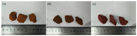
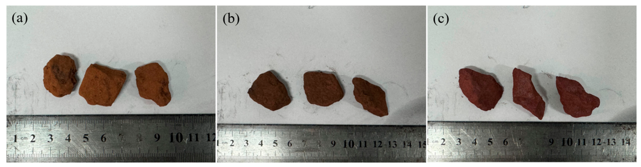
Three commercial lump ores supplied by Baosteel Zhanjiang Iron & Steel Co., Ltd. (Zhanjiang, China) were selected for this study and designated as Lump Ore 1, Lump Ore 2, and Lump Ore 3. The macroscopic appearance of the three representative lump ores used in this study was shown in Figure 1. The particle size of all three ores was predominantly in the range of 10–40 mm, as shown in Table 1.
Figure 1.
Macroscopic appearance of lump ore (a) Lump Ore 1; (b) Lump Ore 2; (c) Lump Ore 3.
Table 1.
Particle size distribution of the raw lump ores (mass fraction) %.
The chemical compositions of the raw materials were listed in Table 2. All three ores had total iron (TFe) contents above 62%, with low gangue contents. Lump Ore 1 exhibited a high loss on ignition (LOI) of 12.58%, indicating poor thermal stability at high temperature. Lump Ore 2 contained a small amount of crystalline water, with intermediate LOI and SiO2 contents. Lump Ore 3 had a low LOI but higher SiO2 and Al2O3 impurity contents.
Table 2.
Main chemical composition and loss on ignition of lump ores (mass fraction) %.
2.2. Experimental Methods
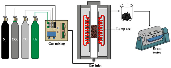
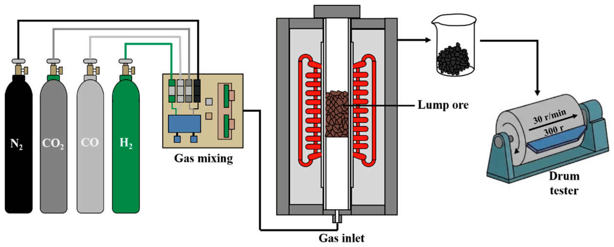
The reduction degradation tests were carried out in a vertical electric resistance furnace; the experimental apparatus and procedure are shown in Figure 2. The H2, CO, CO2, and N2 gases used in the experiments all had a purity of 99.999%. For each test, 500 ± 1 g of sample was weighed out and dried in an oven for at least 2 h. The dried sample was charged into the isothermal zone of the reduction tube and the bed surface was leveled. After the system was sealed, N2 was introduced at a flow rate of 5 L/min and the furnace was heated at a rate of 10 °C/min. Once the furnace temperature reached the set value and had been held for 10 min, the gas was switched to a HYL reducing gas (composition: H2:CO:CO2:N2 = 55:21:14:10, vol% [30]) at a flow rate of 15 L/min. The flow rates of H2, CO, CO2, and N2 were individually regulated using calibrated mass flow controllers and premixed prior to introduction into the reduction tube, ensuring an accurate and stable inlet gas composition throughout each test. After isothermal reduction for the prescribed time, heating was stopped, and the gas was simultaneously switched to N2 at 5 L/min for protection while the sample was cooled to room temperature. After the test, the sample was removed and placed in a tumbling drum, where it was rotated for 300 revolutions at 30 rpm. The reduced lump ore and the resulting powder were then screened using sieves with apertures of 6.3 mm, 3.15 mm and 0.5 mm. The reduction degradation indices, RDI+6.3mm, RDI−3.15mm, and RDI−0.5mm of the lump ore were calculated as follows. RDI+6.3mm represents the mass percentage of the reduced sample retained on the 6.3 mm sieve after tumbling, whereas RDI−3.15mm and RDI−0.5mm represent the mass percentages passing the 3.15 mm and 0.5 mm sieves, respectively.
where m0 is the mass of the reduced sample prior to tumbling; m+6.3 mm is the mass retained above 6.3 mm; m−3.15 mm is the mass passing 3.15 mm; and m−0.5 mm is the mass passing 0.5 mm. Each experimental condition was independently repeated three times using freshly prepared samples, and the reported degradation index values represent the average of the three replicate tests. Across the repeated tests, the degradation index values showed good consistency, with the relative deviation among replicates generally within ±1.5%, confirming the reproducibility of the experimental results.
Figure 2.
Schematic diagram of the reduction degradation test procedure for lump ore.
2.3. Analysis and Characterization
The raw and reduced samples were characterized as follows. Mass-loss behavior during heating in air was measured using an STA 449 F3 Jupiter simultaneous thermal analyzer (Netzsch, Selb, Germany) in accordance with GB/T 27761-2011 [31]. For each test, approximately 10–13 mg of powdered sample was placed in an Al2O3 crucible (85 μL, with lid) and heated from 30 °C to 1430 °C at a constant heating rate of 10 °C/min under a mixed N2/O2 atmosphere, without an isothermal holding step. Thermal decrepitation was evaluated in a KSL-1400X muffle furnace (Kejing, Hefei, China) according to GB/T 10322.6-2022 [32]. For each test, a sample with a particle size of 20–25 mm and a dry mass of at least 5.0 kg was rapidly heated from room temperature to 700 °C, held at this temperature for 30 min, and then cooled to room temperature in air; the cooled sample was screened using a 6.3 mm square-hole sieve, and the thermal decrepitation index was calculated from the mass percentage of the sample passing through the sieve. Phase composition was determined with a D8 Advance X-ray diffractometer (Bruker, Karlsruhe, Germany) using Cu Kα radiation (λ = 1.5406 Å) at 40 kV and 40 mA. Patterns were collected over a 2θ range of 10–80° with a step size of 0.02° and a scan speed of 5°/min, and phases were identified by comparison with reference data from the ICDD PDF-4+ (2009) database (International Centre for Diffraction Data, Newtown Square, PA, USA) using Jade9 (Materials Data Inc., Livermore, CA, USA) software. The microstructures and elemental distributions were examined using a Quanta 650 scanning electron microscope (FEI Co., Hillsboro, OR, USA) equipped with an XFlash 6|60 energy-dispersive X-ray spectrometer (Bruker, Karlsruhe, Germany). For SEM observation, the raw and reduced lump ore samples were impregnated with epoxy resin, ground and polished stepwise using SiC abrasive papers followed by diamond polishing to obtain a flat, smooth cross-section, ultrasonically cleaned, dried, and sputter-coated with a thin gold layer prior to observation.
3. Results and Discussion
3.1. Mineral Phases and Thermal Properties of Lump Ores
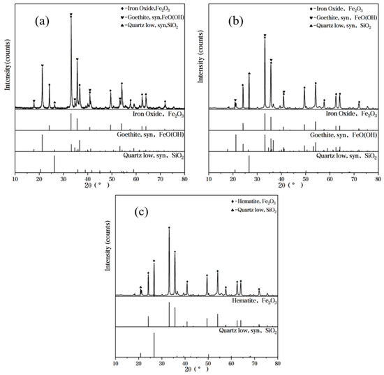
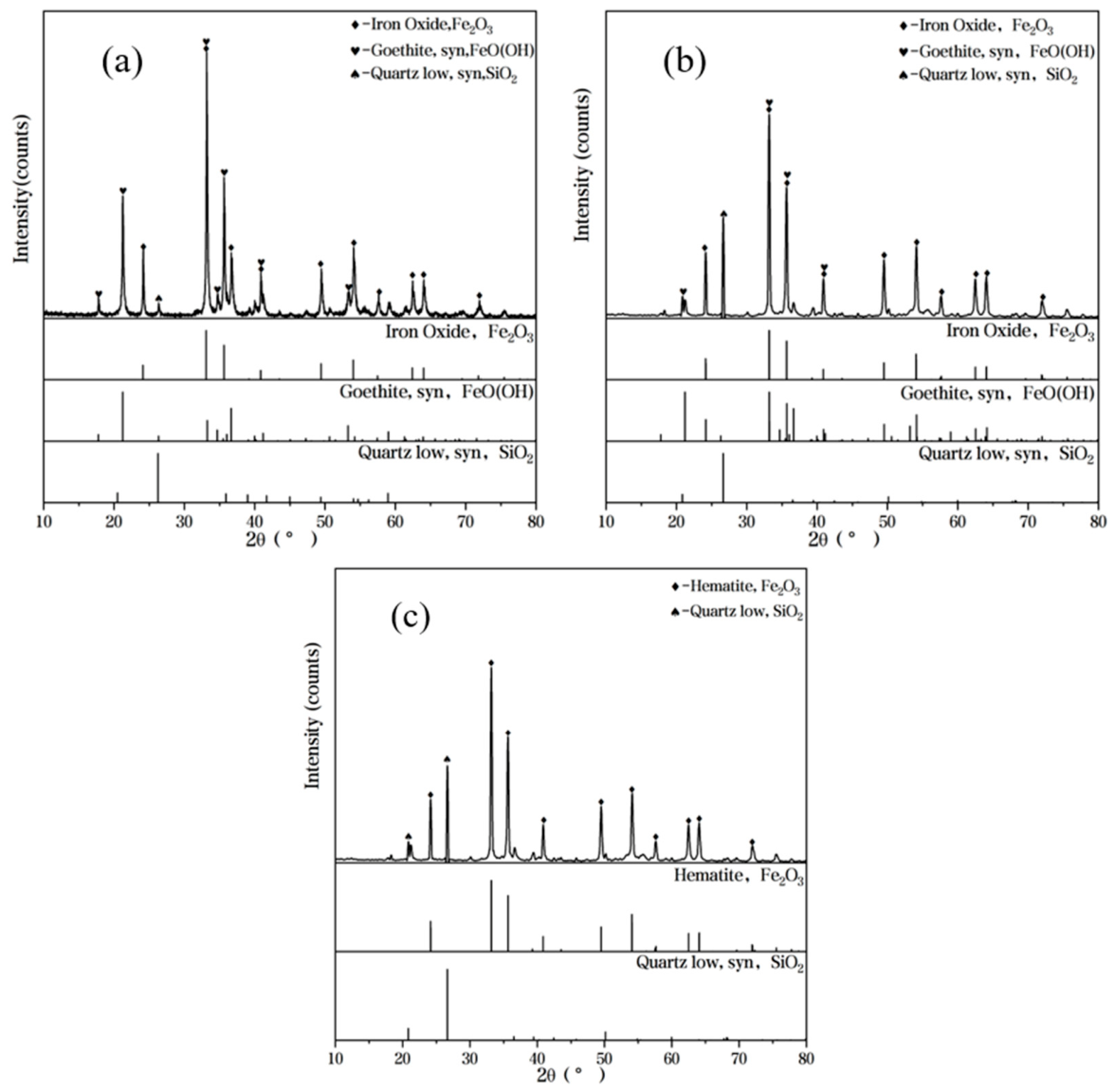
The X-ray diffraction patterns of the three lump ores were shown in Figure 3. Lump Ore 1 mainly contained hematite and goethite as the iron-bearing phases, with quartz as the principal gangue phase, indicating typical limonitic characteristics. A similar hematite–goethite assemblage, together with quartz gangue, was also identified in Lump Ore 2. Lump Ore 3 mainly contained hematite as the iron-bearing phase, with no detectable goethite, and quartz as the dominant gangue phase, indicating typical hematitic characteristics.
Figure 3.
Phase analysis of lump ore (a) Lump Ore 1; (b) Lump Ore 2; (c) Lump Ore 3.
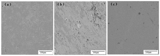
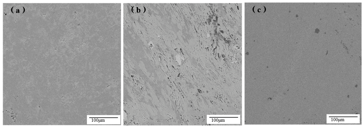
The microstructural features of the three as-received ores were presented in Figure 4. Lump Ore 1 exhibited a relatively compact structure, with closely bonded mineral particles, few pores, and no obvious internal defects. Lump Ore 2 showed a more heterogeneous microstructure, with abundant interparticle pores and internal defects. Lump Ore 3 displayed a relatively uniform and dense structure, with few visible pores or defects. The limited pore space in Lump Ore 1 and Lump Ore 3 restricts stress dissipation during reduction; the abundant pores in Lump Ore 2 provide additional pathways for gas diffusion and help buffer internal stress.
Figure 4.
Microstructural features of lump ore (a) Lump Ore 1; (b) Lump Ore 2; (c) Lump Ore 3.
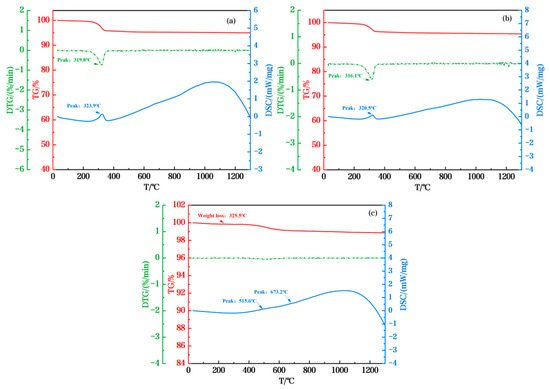
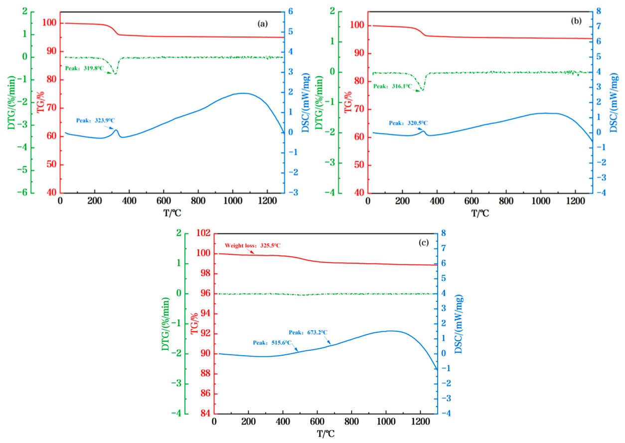
The TG-DSC thermal analysis curves for the three lump ores heated in air were shown in Figure 5. Lump Ores 1 and 2 exhibited their principal crystalline water release between 200 °C and 400 °C. Mass loss began at approximately 200 °C and accelerated sharply near 320 °C, accompanied by a distinct endothermic event. The mass losses attributed to crystalline water removal within this temperature range were 4.95% and 4.54%, respectively. Above 400 °C, the TG curves gradually leveled off, and the total mass losses over the entire heating process were 7.51% and 7.17%, respectively. By contrast, Lump Ore 3 showed only a gradual mass loss above 400 °C, with a total mass loss of 3.53%.
Figure 5.
Thermal analysis curve of lump ores (a) Lump Ore 1; (b) Lump Ore 2; (c) Lump Ore 3.
The thermal decrepitation index (DI) below 6.3 mm, DI−6.3mm, of the three lump ores is listed in Table 3. Lump Ore 2 exhibited the highest decrepitation index and the poorest thermal stability. Lump Ore 3 showed the greatest resistance to thermal decrepitation, with a DI−6.3mm value of only 4.80%. The combined TG–DSC and thermal decrepitation results indicated that Lump Ore 1 had the highest crystalline water content and underwent rapid dehydration near 320 °C. Although Lump Ore 2 had a similar crystalline-water content and decomposition temperature, its decrepitation index was substantially higher than that of Lump Ore 1, which was 5.21%. These results demonstrated that both the mineral assemblage and thermal properties governed crystalline water release and thermal cracking upon heating, thereby weakening the ore structure and promoting subsequent reduction degradation.
Table 3.
Thermal decrepitation property of lump ore (mass fraction) %.
The three lump ores showed clear differences in mineralogical composition and initial structure. Lump Ore 1 exhibited a compact structure with pronounced dehydration characteristics, Lump Ore 2 possessed a developed pore network, whereas Lump Ore 3 exhibited the most compact structure among the three ores.
3.2. Effect of Reduction Temperature on the Reduction Degradation Behavior of Lump Ore
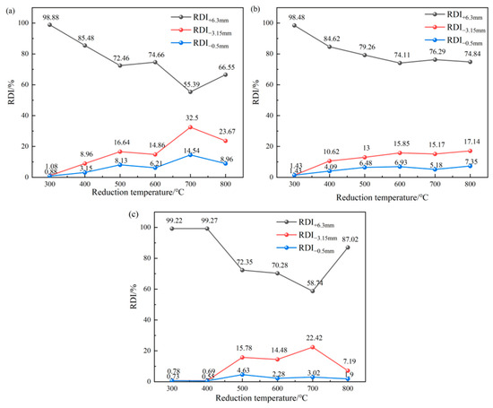
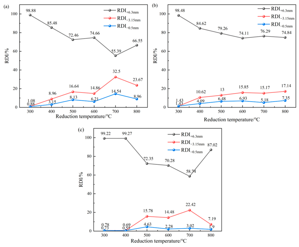
The effect of reduction temperature on the degradation behavior of lump ores was investigated at a fixed reduction time of 1 h under an HYL atmosphere, and the results were shown in Figure 6. With increasing reduction temperature, the RDI−3.15mm of all three lump ores first increased to different extents and then decreased. The RDI−3.15mm of Lump Ore 1 and Lump Ore 3 increased sharply as the temperature rose from 300 °C, and both reached their maximum values at 700 °C. At this temperature, RDI−3.15mm for Lump Ore 1 and Lump Ore 3 reached peak values of 32.50% and 22.42%, respectively. When the temperature increased to 800 °C, the RDI−3.15mm decreased, especially for Lump Ore 3, whose RDI−3.15mm rapidly dropped to below 8%. In contrast, Lump Ore 2 showed a much more gradual variation over the whole temperature range, without severe fluctuation, and its fine fraction, RDI−3.15mm, remained below 18%.
Figure 6.
Effect of reduction temperature on reduction degradation of lump ore after 1 h of reduction (a) Lump Ore 1; (b) Lump Ore 2; (c) Lump Ore 3.
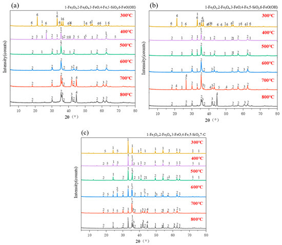
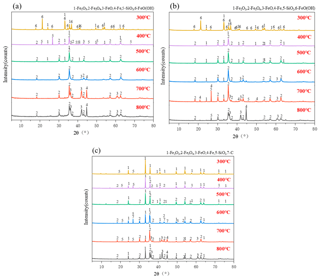
The phase evolution of the three lump ores with reduction temperature was shown in Figure 7. After reduction at 300 °C, the reduced samples were composed mainly of hematite, and Lump Ore 1 and Lump Ore 2 still contained goethite; no obvious phase transformation occurred in any of the three ores. At 400 °C, the peaks of hematite decreased sharply and characteristic peaks of magnetite appeared, indicating large scale transformation of the iron-bearing phases and volumetric expansion of the lump ore. In addition, the goethite peaks in Lump Ore 1 and Lump Ore 2 disappeared completely after reduction at 400 °C, suggesting that dehydration and the initial reduction reaction occurred simultaneously. The superposition of these processes led to severe degradation.
Figure 7.
Phase evolution law of three types of lump ore during reduction process with temperature variation (a) Lump Ore 1; (b) Lump Ore 2; (c) Lump Ore 3.
Compared with Lump Ore 1 and Lump Ore 2, Lump Ore 3 showed no obvious phase transformation at 400 °C, with only a small amount of magnetite generated; strong magnetite diffraction peaks did not appear until the reduction temperature reached 500 °C. At 600 °C, the degree of reduction increased, the reduction of hematite to magnetite was nearly complete, and the reduced lump ores were mainly composed of magnetite and wüstite. In Lump Ore 1, hematite had disappeared completely and metallic iron appeared first, whereas hematite remained in Lump Ore 2 and Lump Ore 3 and metallic iron was not detected until 700 °C, indicating that the reduction progress of Lump Ore 1 was comparatively more advanced than that of Lump Ore 2 and Lump Ore 3.
At 700 °C, the volume expansion stress associated with the hematite-to-magnetite transformation, the lattice reorganization accompanying the magnetite-to-wüstite transition, and the contraction stress generated during the wüstite-to-metallic iron transformation coexisted within the lump ore. The superposition of these multiple phase transformation stresses, acting on a matrix already weakened by the earlier dehydration of crystalline water, together with differences in the rates of the individual reduction reactions, caused the degradation index to reach a maximum. Above 700 °C, the hematite-to-magnetite reaction was essentially complete, and the dominant reactions were Fe3O4 to FeO and FeO to Fe, so that the stress of phase transformation decreased substantially. The reduced lump ore was mainly composed of magnetite, wüstite, and metallic iron. Because metallic iron had higher plasticity and toughness, it was less prone to fragmentation during tumbling and screening, and the degradation index decreased markedly. Among the three ores, Lump Ore 3 had the densest structure and the lowest reduction rate, resulting in slow phase transformation, unreduced hematite persisted throughout the temperature range 300–800 °C.
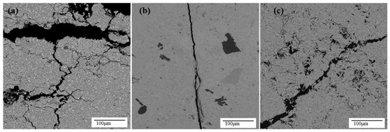
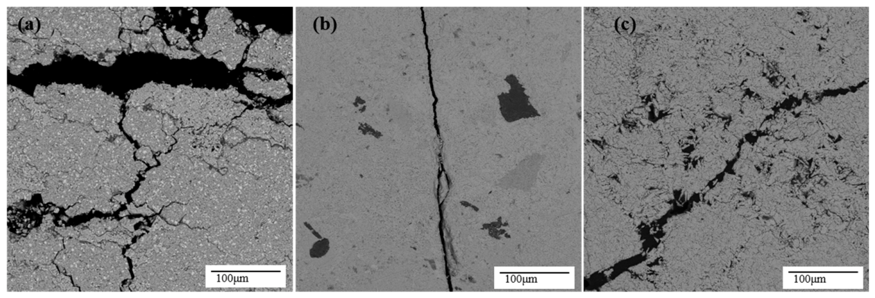
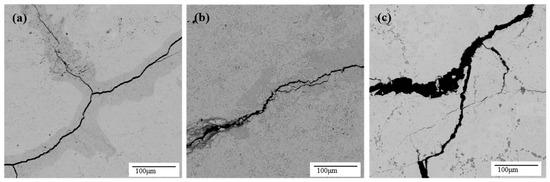
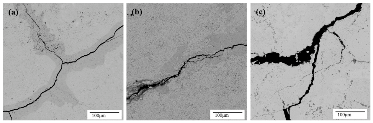
The samples reduced at 700 °C, where degradation was the most severe, were selected for microstructural analysis, as shown in Figure 8. After reduction at 700 °C, Lump Ore 1 exhibited obvious structural damage and became loose. Complete decomposition of internal combined water was superimposed on the phase transformation stresses generated by the reduction reactions, destroying the originally dense structure. Large primary cracks formed, and numerous secondary cracks propagated outward from them. In Lump Ore 2, the original porous structure allowed the reducing gas to diffuse more uniformly, making the reduction rate in different regions relatively balanced. The stresses from phase transformation remained less localized, and the microstructure of the reduced sample stayed comparatively uniform and intact. Although Lump Ore 3 had no dehydration stress associated with combined-water removal, its dense structure caused large differences in the internal reduction rate at 700 °C. The concentrated release of phase transformation stress severely damaged the microstructure and markedly increased the degradation index.
Figure 8.
Microstructural morphology characteristics of lump ore after 1 h reduction in HYL atmosphere at 700 °C (a) Lump Ore 1; (b) Lump Ore 2; (c) Lump Ore 3.
The reduction degradation behavior of lump ore is closely related to its phase evolution and microstructure. Lump Ore 1 has a higher reduction rate and undergoes intense dehydration; at 700 °C, the superposition of multiple phase transformation stresses causes collapse of the overall structure. In Lump Ore 2, the primary porous structure makes the reaction degree in different regions more uniform, promotes stress dispersion, and results in less severe microstructural damage. In Lump Ore 3, the dense structure causes phase transformation stress to be released intensively at 700 °C, leading to severe structural damage.
3.3. Effect of Reduction Time on the Reduction Degradation Behavior of Lump Ore
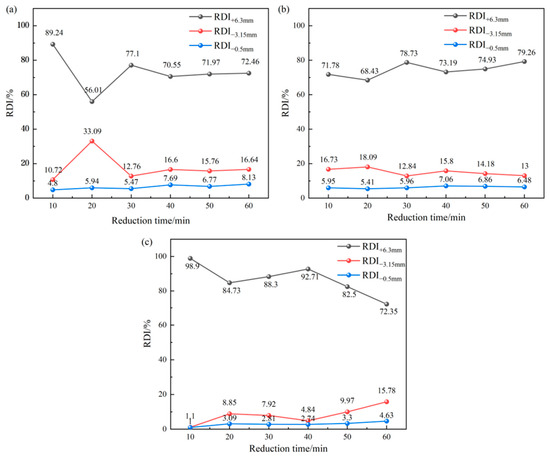
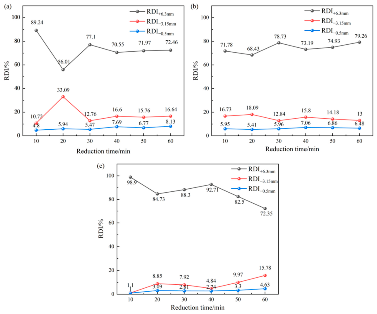
The effect of reduction time (10–60 min) on lump ore degradation at 500 °C under HYL atmosphere is shown in Figure 9. The degradation index of all three ores reached high values at 20 min and then declined at 30 min, indicating that a crystal transformation from hematite to magnetite occurred during this stage. This transformation was accompanied by significant volumetric expansion and generated anisotropic internal stress, leading to degradation. The degradation index of Lump Ore 1 and Lump Ore 2 showed a downward trend over the 40–60 min interval, indicating that their reduction process had been completed and the structure had entered a stable period. In contrast, the degradation index of Lump Ore 3 continued to rise substantially after 40 min, indicating its reduction reaction rate was slower and the reducing gas diffusion inside the ore was hindered. The reaction front advanced progressively from the surface toward the core as the reduction time increased.
Figure 9.
Effect of reduction time on reduction degradation of lump ore at 500 °C (a) Lump Ore 1; (b) Lump Ore 2; (c) Lump Ore 3.
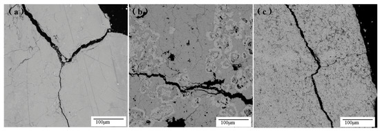
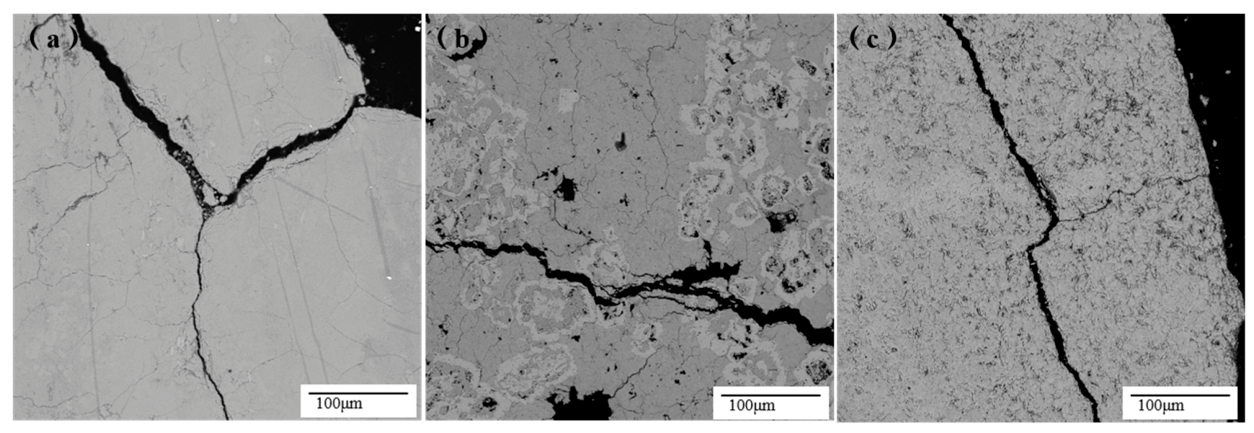
To reveal the influence of reduction time on degradation behavior, samples reduced for 20 min and 1 h, which showed the most pronounced degradation, were selected for microstructural analysis. The results are shown in Figure 10 and Figure 11. Figure 10 shows the microstructures after reduction for 20 min at 500 °C in the HYL atmosphere. The basic structure of Lump Ore 1 was relatively uniform but developed a distinct through-going crack. The crack provided a rapid pathway for the reducing gas, enabling the interior and exterior to react almost simultaneously and causing severe degradation within a short period. The cracks in Lump Ore 2 at 20 min were more tortuous and were surrounded by numerous micropores and fine fissures, which dispersed the gas more diffusely and uniformly upon entering the interior and prevented it from reaching the deep regions directly. Consequently, although the degradation index of Lump Ore 2 also reached a relatively high value at 20 min, the extent of degradation was more moderate. Lump Ore 3 had more tightly packed grains and lower porosity, the reducing gas could not diffuse directly into the interior and reduction could only start from the surface. At 20 min, only a few cracks had appeared in the outer layer while the overall morphology remained well preserved, so the degradation was not severe.
Figure 10.
Microstructural morphology characteristics of lump ore after 20 min reduction in HYL atmosphere at 500 °C (a) Lump Ore 1; (b) Lump Ore 2; (c) Lump Ore 3.
Figure 11.
Microstructural morphology characteristics of lump ore after 1 h reduction in HYL atmosphere at 500 °C (a) Lump Ore 1; (b) Lump Ore 2; (c) Lump Ore 3.
Figure 11 shows the microstructures after reduction for 1 h at 500 °C in the HYL atmosphere. Compared with the 20 min samples, cracks in Lump Ore 1 further propagated and coalesced after 1 h reduction. The cracks formed at the early stage served as pathways for rapid inward gas transport. Once the principal phase transformation stage had passed, structural damage was essentially complete, and the degradation index decreased between 40 and 60 min. The cracks in Lump Ore 2 after 1 h of reduction remained relatively tortuous and were accompanied by numerous micropores and fine fissures. These features dispersed the local stresses, slowing crack propagation and producing only small fluctuations in degradation with time. Wider cracks were formed in Lump Ore 3 after 1 h of reduction, indicating that under conditions of high compactness and restricted gas diffusion, the reduction front advanced gradually toward the interior and the phase transformation stress accumulating continuously at local sites and finally being released in the form of cracking. So the degradation index of Lump Ore 3 continued to rise beyond 40 min.
The reduction degradation behavior of the lump ores is closely related to the compactness of their microstructure and to the reduction kinetics. The through-going cracks in Lump Ore 1 enable rapid internal reduction over a short period; the porous structure in Lump Ore 2 distributes the reducing gas uniformly within the ore, resulting in small fluctuations in degradation index with reduction time; and the dense structure of Lump Ore 3 slows the reduction reaction.
3.4. Reduction Degradation Mechanisms
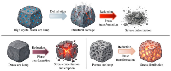
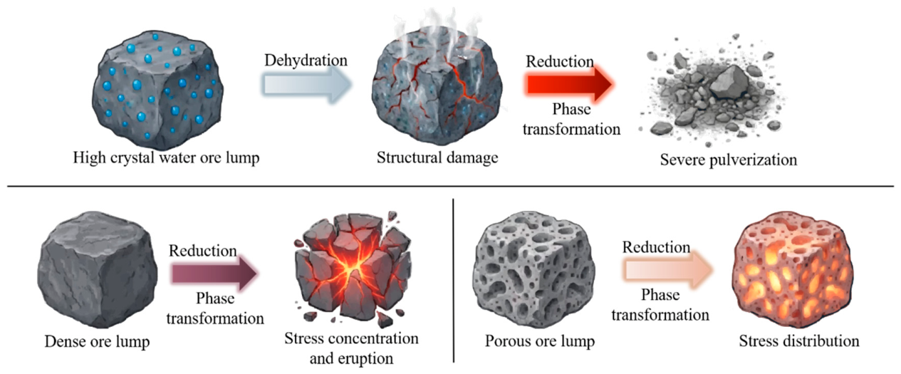
Based on the experimental results describing the effects of reduction temperature and reduction time on degradation, as presented in Section 3.2 and Section 3.3, the distinct pulverization behaviors of the three lump ores are schematically illustrated in Figure 12. The differences in their mineralogical structures lead to three contrasting stress accommodation and release pathways during reduction.
Figure 12.
Stress release mechanisms of lump ore with different mineralogical characteristics.
As illustrated in Figure 12, the high crystal water ore lump (Lump Ore 1) undergoes rapid and intense dehydroxylation of goethite near 320 °C, which causes mass loss and creates a weakened mineral matrix. When the subsequent reduction of hematite to magnetite occurs, the volume expansion stress acts directly on this already damaged skeleton, initiating macrocracks and causing severe structural collapse. The porous ore lump (Lump Ore 2) contains abundant pores and channels, consistent with the intricately intergrown microstructure observed by SEM. Its existing pore pathways promote uniform reducing gas distribution and help buffer and dissipate phase transformation strain. As a result, its cracking remains extensively localized, and the degradation index stays remarkably stable. In the dense ore lump (Lump Ore 3), high compactness severely hinders gas diffusion, forcing the reduction reaction to proceed slowly from the exterior inward. The persistence of unreduced hematite detected by XRD reflects this slow progress. Because of this dense structure, the phase transformation stress cannot be dispersed and instead concentrates locally. Once the accumulated stress exceeds the matrix strength, it leads to abrupt fragmentation, matching the wide cracks formed after 1 h of reduction.
4. Conclusions
This study systematically investigated the reduction degradation behavior of three lump ores under different reduction conditions. The following conclusions can be drawn.
- (1)
- The degradation index of all three lump ores first increased and then decreased with increasing reduction temperature, reaching their maximum values at 700 °C. At this temperature, the transformations of hematite to magnetite, magnetite to wüstite, and wüstite to metallic iron occurred concurrently. The superposition of stresses generated during these phase transformations caused severe structural damage to the lump ores.
- (2)
- The degradation index of all three lump ores increased sharply at 20 min. During this stage, an intense phase transformation from hematite to magnetite took place. Lump Ore 1 and Lump Ore 2 reached a stable stage relatively quickly, whereas the degradation index of Lump Ore 3 continued to increase after 40 min because its reduction was limited by inward gas diffusion. This indicated that the reduction progression differed markedly among the ores. The phase evolution result showed that the reduction process proceeded fastest in Lump Ore 1, followed by Lump Ore 2, and was slowest in Lump Ore 3.
- (3)
- Lump Ore 1 contained a large amount of crystalline water, and the structural damage caused by dehydration resulted in the most severe reduction degradation. The inherent pore network of Lump Ore 2 redistributed phase transformation stresses, leading to a comparatively stable degradation response. Lump Ore 3 contained no combined water and had a strong framework. Its dense structure led to a slow reduction rate and relatively good resistance to reduction degradation.
For hydrogen-based shaft furnace operation, lump ores with a low crystalline water content, good thermal stability, and sufficient structural strength are preferred. These characteristics reduce structural damage during heating and allow the ore to withstand the stress generated during reduction, thereby suppressing degradation.
Author Contributions
Conceptualization, S.W. and H.H.; Methodology, F.C., Y.G. and H.H.; Software, H.H., S.W. and L.Y.; Validation, R.H., M.Z. and M.L.; Formal analysis, R.H., M.Z., M.L. and H.H.; Investigation, M.L. and H.H.; Resources, M.Z., and L.Y.; Writing—original draft, H.H.; Writing—review & editing, F.C., Y.G. and H.H.; Visualization, S.W., L.Y. and H.H.; Supervision, Y.G. and R.H.; Project administration, F.C. and Y.G.; Funding acquisition, F.C., Y.G. and R.H. All authors have read and agreed to the published version of the manuscript.
Funding
This work was supported by the National Natural Science Foundation of China [51904348].
Data Availability Statement
The original contributions presented in this study are included in the article. Further inquiries can be directed to the corresponding author.
Conflicts of Interest
Author Renyi Han, Mingxing Zhu, and Mengtu Li were employed by the company Baosteel Zhanjiang Iron & Steel Co., Ltd. The remaining authors declare that the research was conducted in the absence of any commercial or financial relationships that could be construed as a potential conflict of interest.
References
- Fan, Z.; Friedmann, S.J. Low-Carbon Production of Iron and Steel: Technology Options, Economic Assessment, and Policy. Joule 2021, 5, 829–862. [Google Scholar] [CrossRef] [Scilit]
- Rechberger, K.; Spanlang, A.; Sasiain Conde, A.; Wolfmeir, H.; Harris, C. Green Hydrogen-Based Direct Reduction for Low-Carbon Steelmaking. Steel Res. Int. 2020, 91, 2000110. [Google Scholar] [CrossRef] [Scilit]
- Fei, Y.; Guan, X.; Kuang, S.; Yu, A.; Yang, N. A Review on the Modeling and Simulation of Shaft Furnace Hydrogen Metallurgy: A Chemical Engineering Perspective. ACS Eng. Au 2024, 4, 145–165. [Google Scholar] [CrossRef] [Scilit]
- Ji, Y.; Chi, Z.; Yuan, S.; Chen, Y.; Li, Y.; Jiang, T.; Liu, X.; Zhang, W. Development and Application of Hydrogen-Based Direct Reduction Iron Process. Processes 2024, 12, 1829. [Google Scholar] [CrossRef] [Scilit]
- Spreitzer, D.; Schenk, J. Reduction of Iron Oxides with Hydrogen-A Review. Steel Res. Int. 2019, 90, 1900108. [Google Scholar] [CrossRef] [Scilit]
- Chen, B.; Chen, M.; Hu, M.; Ma, K.; Liu, H.; Bai, C. Development of Hydrogen Metallurgy in China. In Proceedings of the 56th International October Conference on Mining and Metallurgy, Bor Lake, Serbia, 22–25 October 2025; pp. 13–16. [Google Scholar] [CrossRef] [Scilit]
- Han, X.; Liu, H.; Li, L.; Li, P.; Guo, X. The Role of Hydrogen Based Shaft Furnaces in Steel Industry Decarbonization. In Proceedings of the 56th International October Conference on Mining and Metallurgy, Bor Lake, Serbia, 22–25 October 2025; pp. 281–286. [Google Scholar] [CrossRef] [Scilit]
- Tenova. Sinosteel and Tenova Complete ENERGIRON DRI Plant Performance Test at Baosteel. Available online: https://tenova.com/newsroom/latest-tenova/sinosteel-and-tenova-complete-energiron-dri-plant-performance-test-baosteel (accessed on 24 June 2026).
- Li, Q.; Wang, P.; Wang, F.; Zhang, Y.; Wang, H.; Xu, Q.; Xu, M.; Bai, L. Low-Carbon Production in China’s Iron and Steel Industry: Technology Choices, Economic Assessment, and Policy. Atmosphere 2025, 16, 252. [Google Scholar] [CrossRef] [Scilit]
- Zhang, S.; Cheng, Y.; Liu, P.; Yan, R.; Jin, Y.; Chai, Y. Review on the Application of Lump Ore in Blast Furnace Smelting: Trend and Potential Analysis of Energy Saving and Emission Reduction—Taking Chinese Iron and Steel Enterprises as an Example. Metals 2026, 16, 542. [Google Scholar] [CrossRef] [Scilit]
- Zhao, Z.; Tang, J.; Chu, M.; Feng, J.; Li, S.; Qin, J.; Li, F.; Yuan, L. Reduction Behavior of Lump Ore and Its Applicability During Hydrogen-Based Shaft Furnace Process. J. Sustain. Metall. 2024, 10, 2534–2544. [Google Scholar] [CrossRef] [Scilit]
- Norgate, T.; Haque, N. Energy and Greenhouse Gas Impacts of Mining and Mineral Processing Operations. J. Clean. Prod. 2010, 18, 266–274. [Google Scholar] [CrossRef] [Scilit]
- Zhu, D.; Jiang, Y.; Pan, J.; Yang, C. Study of Mineralogy and Metallurgical Properties of Lump Ores. Metals 2022, 12, 1805. [Google Scholar] [CrossRef] [Scilit]
- Barustan, M.I.A.; Copland, E.; Nguyen, T.B.T.; O’Dea, D.; Honeyands, T. Reduction Degradation of Lump, Sinter, and Pellets in Blast Furnace with Hydrogen Injection. ISIJ Int. 2024, 64, 1517–1527. [Google Scholar] [CrossRef] [Scilit]
- Chen, F.; Li, H.; Wang, S.; Chen, M.; Tang, W.; Guo, Y.; Wen, Y.; Yang, L. Reduction Disintegration Behavior and Mechanism of Vanadium–Titanium Magnetite Pellets During Hydrogen-Based Reduction. Metals 2025, 15, 700. [Google Scholar] [CrossRef] [Scilit]
- Hayes, P.C.; Grieveson, P. Microstructural Changes on the Reduction of Hematite to Magnetite. Metall. Trans. B 1981, 12, 579–587. [Google Scholar] [CrossRef] [Scilit]
- Guo, L.; Zhong, S.; Bao, Q.; Gao, J.; Guo, Z. Nucleation and Growth of Iron Whiskers During Gaseous Reduction of Hematite Iron Ore Fines. Metals 2019, 9, 750. [Google Scholar] [CrossRef] [Scilit]
- Kim, S.-H.; Zhang, X.; Ma, Y.; Souza Filho, I.R.; Schweinar, K.; Angenendt, K.; Vogel, D.; Stephenson, L.T.; El-Zoka, A.A.; Mianroodi, J.R.; et al. Influence of Microstructure and Atomic-Scale Chemistry on the Direct Reduction of Iron Ore with Hydrogen at 700 °C. Acta Mater. 2021, 212, 116933. [Google Scholar] [CrossRef] [Scilit]
- Bai, Y.; Mianroodi, J.R.; Ma, Y.; da Silva, A.K.; Svendsen, B.; Raabe, D. Chemo-Mechanical Phase-Field Modeling of Iron Oxide Reduction with Hydrogen. Acta Mater. 2022, 231, 117899. [Google Scholar] [CrossRef] [Scilit]
- Yang, J.; Li, L.; Liang, Z.; Peng, X.; Deng, X.; Li, J. Direct Reduction of Iron Ore Pellets by H2–CO Mixture: An In Situ Investigation of the Evolution and Dynamics of Swelling. Mater. Today Commun. 2023, 36, 106940. [Google Scholar] [CrossRef] [Scilit]
- Wu, S.; Liu, X.; Wu, J. Reduction Disintegration Behavior of Lump Ore in COREX Shaft Furnace. ISIJ Int. 2015, 55, 1608–1616. [Google Scholar] [CrossRef] [Scilit]
- Chen, H.; Zheng, Z.; Chen, Z.; Bi, X. Reduction of Hematite (Fe2O3) to Metallic Iron (Fe) by CO in a Micro Fluidized Bed Reaction Analyzer: A Multistep Kinetics Study. Powder Technol. 2017, 316, 410–420. [Google Scholar] [CrossRef] [Scilit]
- Ma, Y.; Souza Filho, I.R.; Bai, Y.; Schenk, J.; Patisson, F.; Beck, A.; van Bokhoven, J.A.; Willinger, M.G.; Li, K.; Xie, D.; et al. Hierarchical Nature of Hydrogen-Based Direct Reduction of Iron Oxides. Scr. Mater. 2022, 213, 114571. [Google Scholar] [CrossRef] [Scilit]
- Ma, Y.; Souza Filho, I.R.; Zhang, X.; Nandy, S.; Barriobero-Vila, P.; Requena, G.; Vogel, D.; Rohwerder, M.; Ponge, D.; Springer, H.; et al. Hydrogen-Based Direct Reduction of Iron Oxide at 700 ℃: Heterogeneity at Pellet and Microstructure Scales. Int. J. Miner. Metall. Mater. 2022, 29, 1901–1907. [Google Scholar] [CrossRef] [Scilit]
- Zakeri, A.; Coley, K.S.; Tafaghodi, L. Hydrogen-Based Direct Reduction of Iron Oxides: A Review on the Influence of Impurities. Sustainability 2023, 15, 13047. [Google Scholar] [CrossRef] [Scilit]
- Strezov, V.; Evans, T.J.; Zymla, V.; Strezov, L. Structural Deterioration of Iron Ore Particles During Thermal Processing. Int. J. Miner. Process. 2011, 100, 27–32. [Google Scholar] [CrossRef] [Scilit]
- Pineau, A.; Kanari, N.; Gaballah, I. Kinetics of Reduction of Iron Oxides by H2: Part I—Low-Temperature Reduction of Hematite. Thermochim. Acta 2006, 447, 89–100. [Google Scholar] [CrossRef] [Scilit]
- Zhang, J.L.; Hao, L.L.; Liu, Z.J.; Feng, B.; Niu, L.; Li, S.; Li, Z.; Wang, Y. The Temperature of Pretreatment on Microstructure Change of Lump Ore and Improvement of Metallurgical Properties. Steel Res. Int. 2024, 95, 2400074. [Google Scholar] [CrossRef] [Scilit]
- Findorák, R.; Miškovičová, Z.; Legemza, J.; Dzurňák, R.; Bul’ko, B.; Demeter, P.; Egryová, A.; Maliňák, R. Experiments and Simulations on the Low-Temperature Reduction of Iron Ore Oxide Pellets with Hydrogen. Metals 2025, 15, 289. [Google Scholar] [CrossRef] [Scilit]
- HYL Technologies, S.A. de C.V. Evaluation of Iron Ore Pellet for Its Use in a Direct Reduction Process; HYL Technologies, S.A. de C.V.: San Nicolás de los Garza, Mexico, 2012. [Google Scholar]
- GB/T 27761-2011; Standard Test Method of Mass Loss and Residue Measurement Validation of Thermogravimetric Analyzers. Standards Press of China: Beijing, China, 2011.
- GB/T 10322.6-2022; Iron Ores for Blast Furnace Feedstocks—Determination of the Decrepitation Index. Standards Press of China: Beijing, China, 2022.

Disclaimer/Publisher’s Note: The statements, opinions and data contained in all publications are solely those of the individual author(s) and contributor(s) and not of MDPI and/or the editor(s). MDPI and/or the editor(s) disclaim responsibility for any injury to people or property resulting from any ideas, methods, instructions or products referred to in the content. |
© 2026 by the authors. Licensee MDPI, Basel, Switzerland. This article is an open access article distributed under the terms and conditions of the Creative Commons Attribution (CC BY) license.