


Abstract
This study investigates hydrogen-assisted fatigue crack growth (FCG) in vintage pipeline steels to quantify grade-dependent degradation under hydrogen–natural gas blending conditions. Fatigue behavior was evaluated using compact-tension specimens extracted from API X52 and X70 pipeline steels and tested in natural gas–hydrogen mixtures at a total pressure of 6.9 MPa and ambient temperature. Hydrogen concentration was systematically varied from 0% to 100% H2 to assess its influence on crack-length evolution, fatigue crack growth rate, and fracture morphology. Crack propagation was characterized as a function of the stress-intensity-factor range, and scanning electron microscopy was used to examine hydrogen-induced changes in fracture mechanisms. The results demonstrate that FCG accelerates as hydrogen concentration increases, with a strong dependence on steel grade. X70 exhibited substantially greater hydrogen-induced FCG acceleration than X52, despite showing better fatigue resistance under hydrogen-free conditions. Fatigue life reductions approached 60% for X70 at 100% hydrogen, compared with approximately 30% for X52 under the same conditions. Significant early-life sensitivity was observed in X70 even at low hydrogen concentrations, whereas X52 showed more pronounced acceleration during later stages of crack growth. The influence of hydrogen was nonlinear and tended to stabilize at elevated blend fractions, indicating a saturation-type response once hydrogen-assisted crack growth became dominant. Fractographic analyses revealed a transition from ductile tearing in natural gas environments to terrace- and facet-controlled crack propagation in hydrogen-rich environments, accompanied by secondary cracking and river-pattern features. These findings demonstrate that hydrogen–natural gas blending can significantly alter fatigue crack growth behavior and relative material performance in pipeline steels, highlighting the need for grade-specific integrity assessment of existing pipeline infrastructure.
1. Introduction
Interest in hydrogen as a low-carbon energy carrier has renewed attention to the integrity of existing natural gas transmission infrastructure. One near-term deployment strategy is blending hydrogen with natural gas in steel pipelines originally designed for methane service. While hydrogen–natural gas (H2–NG) blending can reduce greenhouse gas emissions without immediate system replacement, it also introduces material degradation mechanisms not encountered under conventional natural gas operation. Among these, hydrogen-assisted fatigue crack growth (HA-FCG) is a critical failure mode for pipelines subjected to repeated pressure fluctuations during service [1,2,3].
Transmission pipelines experience repeated pressurization and depressurization during routine operation, start–stop events, and transient flow conditions. These loading cycles can promote fatigue crack initiation and propagation from pre-existing flaws such as manufacturing defects, weld discontinuities, corrosion pits, or service-induced damage. In hydrogen-containing environments, the interplay between cyclic plastic deformation and hydrogen transport to the crack tip can significantly alter crack-growth behavior. Hydrogen may reduce crack-tip ductility, suppress crack closure, and promote localized damage processes that accelerate fatigue-driven failure [4,5]. Consequently, fatigue crack growth in hydrogen environments is governed by coupled mechanical, metallurgical, and environmental effects, making direct extrapolation from hydrogen-free fatigue behavior unreliable [6].
Previous studies have shown that hydrogen gas can accelerate fatigue crack growth in pipeline steels, with sensitivity depending on material strength, microstructure, hydrogen pressure, and loading conditions [7]. Higher-strength pipeline steels are often reported to be more susceptible to hydrogen than lower-strength grades under comparable exposure conditions. However, much of the available literature has focused on pure hydrogen environments, limited hydrogen concentrations, or individual steel grades, which provides an incomplete basis for evaluating pipelines operating under hydrogen–natural gas blending scenarios [8,9]. In particular, systematic fatigue crack growth data across a wide range of hydrogen blend ratios at fixed total pressure remain limited.
Another important limitation is the lack of direct comparison between service-aged pipeline steels tested under identical environmental and loading conditions. Existing pipeline infrastructure contains materials from different production eras, steel grades, and service histories, and these differences can strongly influence hydrogen sensitivity [10,11,12]. Grade designation alone may not fully represent fatigue resistance because crack-growth behavior is affected by microstructural features such as ferrite–pearlite banding, bainitic constituents, inclusions, local hardness variations, and crack-path orientation [11,13,14,15]. Therefore, evaluating vintage pipeline steels under controlled H2–NG blend conditions is essential for understanding how hydrogen affects real pipeline materials rather than idealized laboratory heats.
From a failure-analysis perspective, measuring crack growth rates alone is not sufficient to fully explain hydrogen-assisted fatigue behavior. Fractographic evidence provides critical insight into how hydrogen changes the crack-growth mechanism at the crack tip. In hydrogen-free environments, fatigue crack growth is generally associated with ductile tearing, crack-tip blunting, and tortuous crack paths. In contrast, hydrogen-rich environments can promote more localized crack advance, secondary cracking, terrace-like features, quasi-cleavage-like facets, and river-pattern markings [16,17]. These fracture-surface features help explain why crack growth accelerates and why different steel grades may respond differently to the same hydrogen exposure.
The present study addresses these gaps by experimentally investigating hydrogen-assisted fatigue crack growth in vintage API X52 and X70 pipeline steels under controlled hydrogen–natural gas blending conditions. The novelty of this work lies in the direct comparison of service-aged X52 and X70 steels under identical loading and environmental conditions across six hydrogen concentrations ranging from 0% to 100% H2. Unlike previous studies that primarily examined pure hydrogen, limited blend ratios, or individual steel grades, this study integrates crack-length evolution, – behavior, hydrogen sensitivity at fixed , SEM fractography, and comparison with the ASME B31.12 design curve. This approach enables direct assessment of grade-dependent hydrogen sensitivity, performance reversal, and nonlinear concentration effects under H2–NG blending conditions.
By focusing on experimental crack-growth behavior and fractographic evidence, this study provides an integrity-relevant basis for assessing hydrogen compatibility of existing pipeline steels under H2–NG blended service. The findings clarify how hydrogen concentration affects fatigue life, crack-growth rate, and fracture mechanism, and they highlight the need for grade-specific assessment strategies when considering the reuse or continued operation of natural gas pipelines for hydrogen-containing gas mixtures.
2. Literature Review
Hydrogen transport through steel pipeline infrastructure has been studied for decades, but the rapid growth of hydrogen-driven decarbonization pathways has renewed attention on fatigue-controlled integrity rather than solely on monotonic fracture resistance. In transmission pipelines, cyclic pressure fluctuations, start–stop operations, and transient events generate numerous load cycles that can be exacerbated by fabrication defects, weld discontinuities, corrosion pits, and service-induced flaws. Under these conditions, the governing failure process is often subcritical crack propagation rather than immediate instability. A broad consensus has therefore emerged that HA-FCG is among the most critical degradation mechanisms for assessing fitness-for-service in H2–NG blended operation [18]. Compared with air or inert environments, gaseous hydrogen can increase crack growth rates, modify crack-closure behavior, and alter fracture-surface morphology. These effects depend on the coupled roles of hydrogen availability (pressure/partial pressure and purity), loading history (R-ratio, frequency), and metallurgical state (microstructure, inclusions, weld/HAZ heterogeneity) [10,19,20].
Large, coordinated experimental programs and code development efforts have built an integrity-relevant database of pipeline steels tested under gaseous hydrogen. These efforts include systematic CT-specimen measurements under controlled hydrogen pressures, comparative testing across multiple grades and heats, and targeted studies of weld regions and heat-affected zones. The resulting datasets have supported both mechanistic understanding and code-oriented bounding curves for design and screening [10,21,22]. In this context, X52 and X70 are particularly important: X52 represents a large share of legacy infrastructure and remains a candidate for repurposing, while X70 is widely used in modern transmission systems and is central to any future expansion of hydrogen capacity. The following review synthesizes the literature relevant to these grades, with emphasis on hydrogen-assisted fatigue crack growth behavior, steel-grade dependence, microstructural effects, and H2–NG blending conditions.
2.1. Hydrogen-Assisted Fatigue Crack Growth in X52 Pipeline
A substantial body of literature demonstrates that X52 pipeline steel exhibits measurable hydrogen-induced acceleration of fatigue crack growth under cyclic loading compared with air or inert environments, confirming that cyclic loads can be a more limiting integrity consideration than fixed loads [19,23,24]. Numerous experimental datasets further indicate that the hydrogen effect is strongly ΔK-regime dependent. Hydrogen-assisted FCG acceleration is most pronounced in the near-threshold to lower Paris regimes, where crack advance is governed by crack-tip plasticity and hydrogen transport kinetics. But at higher ΔK values, the crack-driving force becomes dominant, and the relative environmental influence may diminish [25,26,27]. This regime dependence is particularly relevant from a failure-analysis perspective because remaining pipeline life is often dominated by crack propagation through intermediate ΔK ranges once an initial defect has exceeded the incubation stage; consequently, even modest hydrogen-induced acceleration within a specific ΔK window can result in a disproportionate reduction in fatigue life.
Hydrogen pressure and loading frequency are repeatedly identified as primary control variables in testing and interpreting hydrogen-assisted FCG. Comprehensive reviews and experimental syntheses of pipeline steels report that increasing hydrogen pressure generally increases crack growth rates, although the relationship is often nonlinear and may approach saturation at higher pressures, consistent with transport-limited or crack-tip kinetic constraints [23,28,29]. Time-dependent effects are also well documented, with lower cyclic frequencies producing greater acceleration due to increased time for hydrogen redistribution and accumulation within the crack-tip process zone during each loading cycle [19,24]. This trade-off between enhanced hydrogen sensitivity at low frequencies and prohibitive experimental duration has influenced the design of modern high-pressure hydrogen fatigue facilities, in which frequencies on the order of 1 Hz are commonly used to balance sensitivity and practicality [11,24,30].
A critical theme across X52 studies is that the API grade designation does not correspond to a single metallurgical condition. Microstructural features, including ferrite–pearlite fraction, banding severity, inclusion content, grain size, and precipitation state, can vary widely between heats and across vintages, and these variations influence hydrogen trapping and crack-path behavior [11,13,14]. Comparative programs involving vintage and modern line pipe show that steels of similar nominal grade may respond differently to hydrogen exposure, particularly in the low-ΔK regime, where microstructural barriers and crack-tip hydrogen activity strongly control propagation [29]. These observations underscore that integrity assessment for repurposed pipelines must be grounded in material-specific characterization, including microstructure, hardness distribution, and weld condition, rather than grade designation alone.
As near-term deployment scenarios increasingly consider blending hydrogen into natural gas, an important development in the literature is the emergence of fatigue crack growth datasets in H2–CH4 mixed-gas environments. These studies provide two key insights relevant to integrity. First, even relatively low hydrogen fractions can measurably influence crack growth behavior compared with methane baselines, indicating that dilution does not eliminate hydrogen-assisted fatigue risk. Second, the influence of hydrogen blending is both ΔK-dependent and location-dependent. Recent work by Chandra, et al. [31] assessed X52 seam weld regions under 1, 5, and 10 mol% H2 in CH4 and reported that the lowest blend composition remained close to baseline behavior over portions of the ΔK range, whereas higher hydrogen fractions produced consistently elevated crack growth rates relative to methane across the investigated regime. These findings align with the broader concept that hydrogen effects become more pronounced once crack-tip conditions exceed a regime-dependent threshold and underscore that integrity assessments under blended service should not assume a single, constant acceleration factor across all crack sizes and driving forces.
Complementary vintage-pipeline investigations by Agnani, Ronevich, Parker, Gagliano, Potts and San Marchi [12] likewise emphasize the critical role of weld-region heterogeneity and local hardness variations in governing fatigue crack growth in hydrogen-containing environments. Collectively, the X52 literature indicates that robust integrity assessment requires both a realistic representation of the gas environment, including hydrogen blending and purity control, and explicit consideration of the crack-path microstructure, particularly for legacy pipeline systems.
2.2. Hydrogen-Assisted Fatigue Crack Growth in X70 Pipeline
X70 steel is widely used in modern transmission pipelines for its favorable strength-to-weight ratio and material efficiency. However, higher-strength pipeline steels are often considered more susceptible to hydrogen-assisted degradation due to altered crack-tip plasticity, refined or heterogeneous phase morphologies, and potentially higher densities of hydrogen-trapping sites and stress concentrators. Under comparable crack-tip constraint, the peak hydrostatic tensile stress within the plastic zone scales approximately with the yield strength of the steel. This higher stress increases the chemical-potential driving force for hydrogen transport and accumulation near the crack tip, which may contribute to the greater hydrogen sensitivity of higher-strength steels. However, the resulting crack-tip hydrogen concentration also depends on microstructural trapping, diffusivity, and environmental conditions. Consequently, the literature on X70 emphasizes both comparative assessments relative to lower-strength grades and heat-to-heat variability within X70 [15,32].
Experimental investigations consistently report that X70 exhibits hydrogen-accelerated fatigue crack growth in hydrogen-containing environments compared with air or inert environments. Hydrogen exposure is also associated with distinct changes in fracture-surface morphology, often described as a transition from ductile fatigue striations toward more brittle-appearing morphologies characterized by increased secondary cracking and quasi-cleavage-like features under higher hydrogen availability [32]. These fracture-mode transitions are commonly interpreted as signatures of hydrogen-enhanced damage processes operating at the crack tip and are central to failure analysis because they indicate reduced crack-tip blunting and altered crack-propagation mechanisms in hydrogen-containing environments.
Modern X70 steels are typically produced via thermomechanical controlled processing, yielding complex microstructures that may include polygonal ferrite, acicular ferrite, bainitic constituents, and heterogeneous carbide distributions. Studies of microstructure-dependent hydrogen embrittlement and fracture behavior in X70 show that susceptibility cannot be inferred solely from strength. Instead, phase morphology, microstructural refinement, and hydrogen-trapping characteristics govern the extent to which hydrogen accelerates fatigue crack propagation [15]. These observations align with comparative program results showing that within-grade variability can be substantial and that the relative ranking of crack-growth behavior between steels may change with environment and ΔK regime [10].
Weld and heat-affected-zone (HAZ) behavior critically influences the integrity of X70 pipeline steels in hydrogen service, particularly because of pronounced local gradients in hardness, residual stress, and transformation products. Although X70-specific weld fatigue datasets vary with weld process, joint geometry, and notch placement, existing studies consistently show that fatigue crack growth rate can differ markedly within a single joint, depending on whether the crack propagates through parent pipe, weld metal, or specific HAZ subregions. Residual stress and strength mismatch further modify the effective crack driving force, thereby influencing observed crack growth behavior under hydrogen exposure [33]. These findings underscore the need to treat weld microstructures as primary contributors to hydrogen-assisted fatigue risk rather than secondary modifiers.
Blend-focused studies on X70 are particularly relevant to near-term hydrogen–natural gas deployment strategies. In an investigation, Chandra, Thodla, Prewitt, Matthews and Sosa [33] examined X70 with 1, 5, and 10 mol% H2 in methane and reported elevated fatigue crack growth rates relative to methane-only conditions across all evaluated notch locations. The magnitude of acceleration depended on both ΔK and microstructural location. An important implication of this work is that microstructural distinctions are more pronounced at lower hydrogen blend levels, whereas at higher hydrogen contents the response tends to converge toward a uniformly accelerated crack-growth regime, effectively compressing the ranking among locations as hydrogen becomes the dominant factor. From an integrity perspective, this behavior suggests that early-stage blending may preferentially expose location-specific vulnerabilities, whereas higher hydrogen fractions may drive the entire system toward an elevated crack-growth envelope.
Overall, the X70 literature indicates that robust fatigue integrity assessment in hydrogen-containing environments requires simultaneous consideration of hydrogen availability (including blended gas composition), the ΔK regime, and location-specific metallurgy. These findings motivate comparative experimental programs to evaluate X52 and X70 steels under identical loading and environmental conditions, thereby isolating the effects of grade, microstructure, and weld heterogeneity on hydrogen-assisted fatigue crack growth [10,22]. However, despite the widespread deployment of X70 in modern transmission pipelines, fatigue crack growth data for this grade in gaseous hydrogen and hydrogen–natural gas blends remain limited compared with those for lower-strength pipeline steels.
2.3. Integrity Assessment and Need for Controlled Blend Data
Reliable assessment of hydrogen-assisted fatigue crack growth in pipeline steels requires engineering references that account for the combined effects of hydrogen exposure, cyclic loading, and material variability. A prominent outcome of coordinated hydrogen pipeline research programs is the development of conservative fatigue crack growth representations for gaseous hydrogen intended for integrity screening and code application [27]. These approaches typically preserve a Paris-law form, or a piecewise equivalent, with hydrogen effects incorporated through modified parameters or bounding curves. Such curves are useful for screening because they provide conservative fatigue crack growth inputs when detailed material-specific data are unavailable. However, generalized design curves may mask heat-to-heat variability, grade dependence, weld-region effects, and microstructural differences that are clearly observed in experimental studies.
The technical basis for hydrogen pipeline design guidance has been documented in ASME contexts, including the development and rationale for fatigue crack growth rules incorporated in ASME B31.12 [21,34]. These discussions emphasize the role of conservative bounding approaches in supporting safe hydrogen pipeline design and early deployment. However, code-based curves are not intended to replace material- and condition-specific fatigue crack growth characterization when higher-fidelity assessment is required, particularly for existing pipelines with different production histories, steel grades, weld conditions, and service exposure.
For hydrogen–natural gas blending, the need for controlled experimental data is especially important because crack growth behavior may depend on hydrogen partial pressure, total pressure, blend ratio, loading frequency, load ratio, ΔK regime, and local metallurgical condition. Existing datasets for X52 and X70 steels remain fragmented across different test protocols, specimen orientations, gas compositions, and material states. Therefore, direct experimental comparison of vintage X52 and X70 steels under identical H2–NG blend conditions is necessary to clarify grade-dependent hydrogen sensitivity and to evaluate whether generalized screening curves remain conservative across the relevant crack-growth regimes.
3. Methodology
3.1. Specimen Preparation
Carbon-steel pipes commonly used for natural gas transmission were investigated in this work, focusing on API X52 and X70. These grades were selected to represent two practically important classes of existing pipeline infrastructure: X52 as a lower-strength legacy grade widely used in older transmission systems and X70 as a higher-strength grade relevant to modern pipeline construction. Both materials were retrieved from field pipelines that had remained in service for approximately 40–50 years, enabling evaluation of service-aged steels rather than laboratory-produced materials. Original manufacturing records were unavailable; therefore, the exact manufacturing routes could not be independently confirmed. The materials were characterized using their measured chemical compositions, tensile properties, and optical microstructures. The X52 material was obtained from a 36-in.-outer-diameter pipe with a wall thickness of 0.406 in., whereas the X70 material originated from a 30-in.-outer-diameter pipe with a wall thickness of 0.460 in. For each grade, a short nipple section was removed from the parent pipe and axially sectioned into a 12-in.-long segment to serve as the stock material for subsequent specimen fabrication.
Compact-tension (CT) specimens were cut from axially sectioned pipe nipples and machined per ASTM E647–24 for fatigue crack growth (FCG) testing [35]. For both X52 and X70, the CT specimens were machined so that the crack direction aligned with the pipe’s longitudinal axis (Figure 1). In this configuration, cyclic tensile loading is applied transversely, representing the hoop-stress direction, while the fatigue crack advances parallel to the pipe axis. The CT test therefore represents the opening of a longitudinal crack under hoop-dominated loading. However, an operating closed-end pipeline experiences a biaxial stress state comprising both hoop and axial stresses, with the nominal hoop stress being approximately twice the axial stress for a thin-walled pipe. This biaxial stress condition is not reproduced by the present CT-specimen configuration.
Figure 1.
Schematic illustration of CT specimen extraction from vintage pipeline segment, showing the longitudinal (pipe-axis) crack propagation direction and the transverse loading direction used for fatigue crack growth testing.
Figure 2 shows the CT specimen geometry and a representative test-ready sample used in this study. CT specimens for X52 and X70 were fabricated in accordance with ASTM E647–24 to ensure geometric consistency and validity for FCG measurements. The primary dimensions were controlled per the standard CT configuration: the specimen width was maintained at W = 32.0 mm (measured from the load line to the rear edge), and the thickness was fixed at B = 8.0 mm. The final specimen thickness was obtained by machining the parent pipe walls, approximately 10.31 mm for X52 and 11.68 mm for X70, to a uniform out-of-plane thickness of B = 8.0 mm, leaving sufficient allowance to produce flat, parallel side faces for crack-length monitoring and ASTM E647–24 FCG testing. This thickness-to-width ratio falls within the recommended ASTM range for CT specimens and provides adequate crack-tip constraint for stable, repeatable crack-growth testing. The overall height followed the standard 1.2 W (38.4 mm) layout, ensuring compatibility with conventional fixtures and pin-loading arrangements.
Figure 2.
Schematic of the CT specimen geometry used for FCG testing in accordance with ASTM E647–24, showing the principal dimensions (unit: mm).
Two loading holes with a nominal diameter of 8.0 mm were machined to the recommended tolerances and positioned symmetrically about the crack plane to promote uniform load transfer and minimize bending during cyclic loading. Notch and crack starter features were introduced on the front face of each specimen, and the notch root was sharpened by electrical discharge machining (EDM) to create a sharp crack-initiation site and improve the repeatability of fatigue pre-cracking. After machining, specimens were inspected to confirm key dimensions and the alignment of the load line, notch, and hole locations within acceptable tolerances. The side faces were also finished to support consistent crack-length monitoring during testing. Overall, adopting an ASTM-compliant CT geometry and a standardized notch-pre-cracking approach ensured comparable crack-growth behavior across both grades, reducing scatter attributable to machining or geometric variability. Further details on specimen preparation are available in the authors’ previous publication [36].
Before testing, the CT specimens were finished to a controlled surface condition to minimize measurement scatter caused by machining marks or local surface defects. A metallographic polishing sequence produced a smooth, uniform finish, followed by acetone cleaning to remove residual lubricants or grease. Maintaining a consistent surface state across all samples was essential to ensure repeatable hydrogen-assisted crack growth behavior and to isolate material effects from preparation-related variability. The chemical composition and tensile properties of the X52 and X70 steels evaluated in this study are reported in Table 1 and Table 2, respectively. Tensile characterization was conducted under in situ natural-gas conditions (25 °C, 6.9 MPa) at a strain rate of 1.12 × 10⁻⁴ s−1. Three replicate tests were performed for each grade, and the averages are presented. Strain was recorded using an in-house strain-gauge–based system designed to meet ASTM E399-22 requirements, providing extensometer-equivalent accuracy in the pressurized test configuration.
Table 1.
Chemical composition of Grade X52 and X70 steel (wt.%).
Table 2.
Tensile properties of X52 and X70 steel tested in NG.
Microstructural characterization of X52 and X70 steels was performed on sectioned CT specimens prepared to preserve the as-received microstructure and avoid thermal or mechanical damage during extraction. Metallographic surfaces were prepared using a sequential grinding–polishing–etching routine suitable for optical imaging. Specimens were first ground on SiC papers in progressively finer steps (360, 600, 800, 1000, and 1200 grit) using an automated grinder operated at 120 rpm for 10 min per grit; the grinding direction was alternated by 90° midway through each step to promote uniform material removal and reduce preferential scratching. The ground surfaces were then polished in three stages (10 min each) at 100 rpm using diamond suspensions in a glycol-based medium with decreasing particle sizes (3 μm, 1 μm, and 0.05 μm) to achieve a scratch-free, mirror-like finish. To reveal microstructural features, the polished specimens were briefly etched with a nital-type methanol solution prepared by mixing 2 mL HNO3 with 98 mL CH3OH, followed by immediate rinsing in methanol to arrest the reaction. After etching, samples were cleaned in an ultrasonic bath containing methanol for 5–10 min to remove residual etchant and surface debris. Throughout preparation, specimens were degreased with acetone and dried with compressed air between major steps. Microstructures were then examined using a Keyence VHX-7000 optical ultra-microscope (Keyence Corporation, Osaka, Japan).
3.2. Experimental Setup and Procedure
In situ fatigue crack growth experiments were conducted in a custom high-pressure autoclave configured for hydrogen service, as shown in Figure 3. The pressure vessel and associated wetted components were fabricated from corrosion-resistant materials to ensure compatibility with high-purity hydrogen and hydrogen–natural gas mixtures. Test gases were supplied from high-pressure cylinders; hydrogen purity was ≥99.95%, and the natural gas used for the baseline condition was a supplier-certified, dry Linde NG 0.85-T mixture containing more than 85% CH4. Gas delivery, pressurization, and regulation were controlled by an automated system that maintained a stable chamber pressure of 6.9 MPa and reduced operator-dependent variability. This pressure, equivalent to approximately 1000 psi, was selected as a practically relevant transmission-pressure condition for evaluating hydrogen–natural gas blending [37]. Before introducing hydrogen-containing environments, the autoclave was repeatedly evacuated and purged to remove residual air, and outlet oxygen levels were monitored with an inline analyzer to confirm near-zero oxygen before charging. The test temperature was maintained at 25 °C and regulated using an insulated external aluminum jacket coupled to a glycol circulation loop connected to both heating and chilling units, enabling stable control within the desired operating range. This controlled near-ambient temperature was selected to isolate the effects of hydrogen concentration and steel grade without introducing additional temperature-dependent effects.
Figure 3.
Schematic of the high-pressure in situ fatigue-crack growth testing setup.
A dedicated mechanical loading arrangement enabled CT testing inside the pressurized chamber by coupling the internal specimen to an external hydraulic actuator via a pull rod passing through a high-pressure sealing gland. Load control was implemented with a dual-unit configuration: a syringe pump maintained the mean (static) load component (controlling Kmean), while a programmable piston pump imposed the cyclic component to set the amplitude and frequency (controlling ΔK), thereby stabilizing Kmax and Kmin. Fatigue pre-cracking was conducted using a custom pre-crack step, as shown in Figure 4, with a sinusoidal load waveform. An initial pre-crack length of 0–1.7 mm (from the load line) was generated at a load ratio of R = 0.5 and a frequency of 7.8 Hz. The final pre-cracking stage was performed at R = 0.2 and f = 7.8 Hz, with a final stress intensity factor range of ΔK = 9.2 MPa√m, corresponding to Kmax = 11.5 MPa√m. The maximum stress intensity factor during pre-cracking was maintained at or below the initial Kmax used in the subsequent FCG tests, in accordance with ASTM E647–24. Crack development was tracked optically in real time, and each specimen was pre-cracked to a depth of 2.0 ± 0.1 mm from the notch tip, yielding an initial crack length of approximately a0 ≈ 8 mm from the load line (a0/W ≈ 0.25).
Figure 4.
Experimental setup used to fatigue pre-crack CT specimens in air.
Fatigue crack growth tests were then conducted under sinusoidal loading per ASTM E647–24 at a total pressure of 6.9 MPa and room temperature, using high-purity hydrogen and selected hydrogen–natural gas mixtures. The loading ratio R = 0.60 ± 0.1 and a frequency of 8.8 Hz were selected to represent controlled cyclic loading conditions while enabling practical test durations within facility operating constraints. A constant Kmax with an incrementally increasing ΔK profile was used to span a broad driving-force range; representative initial conditions were R ≈ 0.7, ΔK ≈ 5 MPa√m, and Kmax ≈ 18.4 MPa√m, with one CT specimen per condition. Although pipeline pressure fluctuations may occur at frequencies considerably lower than 8.8 Hz, the frequency dependence of hydrogen-assisted fatigue crack growth in carbon and pipeline steels is material- and environment-dependent. Studies on specific X52 and X70 steels reported no strong frequency sensitivity over the investigated range of 1–0.01 Hz, whereas other carbon steels exhibited a non-monotonic response in which crack-growth acceleration increased with decreasing frequency, reached a maximum, and subsequently decreased at very low frequencies [7,24,38,39,40]. Therefore, the present results are used for controlled comparison of hydrogen concentration and steel grade, and direct quantitative extrapolation to service-frequency crack-growth rates is not made.
Because the entire CT specimen was exposed to the pressurized H2–NG environment, hydrogen had direct access to the crack surfaces. Therefore, the present configuration represents fatigue crack growth of gas-contacting flaws, such as internal surface-connected defects, and does not reproduce external cracking associated with coating degradation, soil exposure, cathodic-protection conditions, or through-wall hydrogen transport.
After charging, specimens were exposed to hydrogen for approximately 2 h before cycling began. Depending on the condition, active cycling to failure required approximately 4–12 h, including mounting, autoclave assembly, purging, and pressurization (and daytime-only operation). Each experiment typically spanned 2–3 calendar days. For mixed-gas environments, partial-pressure charging was used to achieve the target composition (e.g., a 25% H2–75% NG condition was prepared by first charging H2 to 25% of the final pressure, then adding NG to reach 6.9 MPa; the sequence was reversed for hydrogen-richer blends). Overnight pauses in cycling were not expected to alter outcomes because hydrogen uptake in low-carbon steels rapidly approaches near-saturation under high-pressure exposure; this assumption is supported by prior studies [41,42,43].
Crack extension during testing was monitored by compliance using a clip gauge mounted on the CT specimen (consistent with the measurement approach in ASTM E399–22), with hydrogen-compatible sensors routed through a high-pressure, wire-sealed feedthrough. Signals were amplified and logged via a data acquisition system. Loading was applied in fixed 30 min blocks at each Kmax, and ΔK and Kmin were calculated from specimen geometry and load as prescribed by ASTM E647–24. After testing, specimens were fractured under monotonic loading to reveal the final crack front. The fatigue-growth and final-overload regions were clearly distinguishable. Fracture surfaces were examined without additional polishing or etching using a Thermo Quattro S field-emission environmental SEM (FE-ESEM) operated in high-vacuum mode at 30 kV, with images collected at multiple magnifications from regions associated with fatigue growth and final overload. Pre-crack and final crack lengths were quantified by optical microscopy using seven measurements along the crack front, and the calculated crack-length histories were linearly corrected to match the physical measurements. Crack-growth rates (da/dN) were obtained by fitting a four-parameter logistic function to the corrected crack-length–cycle data, while stress-intensity factors were computed using standard ASTM E647–24 solutions based on a/W and the applied ΔP. The Stage II fatigue crack growth data were fitted using the Paris relationship, , by linear regression of against , where and are the Paris-law coefficient and exponent, respectively.
3.3. Test Matrix and Gas Environment Conditions
A predefined test matrix was established to quantify the effect of hydrogen content on fatigue crack growth, with the selected environments summarized in Table 3. The same matrix was applied to both X52 and X70 materials. Testing was performed in high-purity hydrogen and in hydrogen–natural gas blends ranging from 0 to 100 vol.% H2. All experiments were conducted at a fixed total pressure of 6.9 MPa using six target compositions: 0%, 10%, 25%, 50%, 75%, and 100% H2 (balance natural gas). The desired blend compositions were prepared using the partial-pressure method, in which each constituent gas was introduced sequentially to its target partial pressure before the vessel was brought to the final total pressure. The 0% H2 condition (i.e., 100% natural gas) served as the baseline at room temperature (25 °C) with no intentional hydrogen or oxygen present, representing conventional pipeline service conditions. This reference enables direct, consistent comparisons across the matrix, allowing changes in crack-growth rate (da/dN) to be attributed to hydrogen concentration. This approach provides a clear basis for evaluating hydrogen-assisted degradation as the environment transitions from natural gas to increasingly hydrogen-rich mixtures.
Table 3.
Gas-environment test matrix for FCG testing of X52 and X70 CT specimens (total pressure = 6.9 MPa).
4. Results and Discussion
4.1. Microstructural Characteristics
The etched microstructures of X52 and X70 steels reveal distinct phase assemblages and morphological features that reflect differences in alloy design and thermomechanical processing routes, consistent with their targeted strength levels and service requirements. Representative microstructures of the two grades are shown in Figure 5.
Figure 5.
Representative etched microstructures of pipeline steels: (a) X52 steel exhibiting a ferrite–pearlite microstructure; (b) X70 steel exhibiting a ferrite-based microstructure with bainitic constituents.
X52 steel exhibits a heterogeneous ferrite–pearlite microstructure (Figure 5a), which is typical of low-carbon, thermo-mechanically processed pipeline steels [44]. The microstructure is dominated by a polygonal ferrite matrix, appearing as light regions, with darker pearlite colonies unevenly distributed. Ferrite grains display a mixed morphology, ranging from equiaxed and polygonal to moderately elongated grains aligned along a preferred direction parallel to the pipe-rolling axis. Pearlite is present as both discrete colonies and semi-continuous regions embedded within the ferritic matrix.
A pronounced banded structure is observed in X52, with alternating ferrite- and pearlite-rich regions aligned parallel to the rolling direction. This banding reflects chemical segregation during solidification, followed by elongation during hot rolling, and is a clear source of microstructural anisotropy. Within pearlite colonies, fine ferrite–cementite lamellae are clearly resolved, confirming the lamellar pearlitic morphology. Variations in lamellar orientation among neighboring colonies indicate differences in local crystallographic alignment and transformation kinetics during cooling. The ferrite–pearlite interfaces are sharp and well defined, indicating effective phase delineation after etching. Occasional elongated nonmetallic inclusions or inclusion stringers aligned with the banding direction are also observed, likely originating from steelmaking impurities that were plastically elongated during rolling.
In contrast, X70 steel exhibits a more refined, complex multiphase microstructure dominated by a continuous polygonal-to-quasi-polygonal ferrite matrix (Figure 5b). Ferrite grains are largely equiaxed with smooth, well-defined boundaries, indicating a predominantly recrystallized ferritic structure. However, localized grain elongation and aligned boundaries suggest a residual deformation texture inherited from thermo-mechanically controlled processing. Compared with X52, the ferritic matrix in X70 appears more uniform, consistent with stricter compositional and thermal control.
Dispersed throughout the ferritic matrix of X70 is a substantial fraction of a darker second-phase constituent with heterogeneous morphology and spatial distribution. This constituent appears as semi-continuous regions decorating ferrite grain boundaries and as irregular intragranular regions. The internal morphology of these regions is fine and non-lamellar, lacking the parallel cementite lamellae characteristic of pearlite, indicating that they correspond primarily to bainitic transformation products, commonly described as bainitic ferrite or granular bainite in high-strength pipeline steels. In addition, small, compact, high-contrast islands are observed within these regions and near ferrite–second-phase interfaces, consistent with martensite–austenite (M–A) constituents formed in locally carbon-enriched regions during transformation [45,46]. Their limited size and discontinuous distribution suggest that they do not form an extensive continuous hard-phase network.
Both steels exhibit microstructural banding aligned with the rolling direction; however, the nature and severity of banding differ substantially. In X52, banding is dominated by high-contrast ferrite–pearlite alternation, whereas in X70 it is weaker and associated with subtle variations in ferrite and bainite distribution. This contrast reflects the transition from ferrite–pearlite strengthening in X52 to ferrite–bainite strengthening in X70, enabled by lower carbon content and enhanced microalloying control.
From a mechanical perspective, the ferrite–pearlite microstructure of X52 introduces pronounced microstructural heterogeneity and anisotropy, particularly along the rolling direction, which aligns with the fatigue crack propagation direction in the present CT specimen orientation. Pearlite-rich bands, ferrite–pearlite interfaces, and elongated inclusions can create localized hardness variations and stress-concentration sites that influence crack-path tortuosity and cyclic crack-growth behavior in hydrogen-containing environments. In contrast, the ferrite–bainite microstructure of X70 provides higher strength through refined ferritic morphology, bainitic constituents, and microalloying effects. Although this microstructure supports improved baseline fatigue resistance under hydrogen-free conditions, its higher strength level and reduced crack-tip plastic accommodation may also increase sensitivity to hydrogen-assisted crack propagation under H2–NG blended environments.
4.2. Hydrogen Concentration Dependent Fatigue Crack-Length Evolution
The fatigue crack-length evolution of X52 and X70 pipeline steels exhibits a strong, quantifiable dependence on hydrogen concentration in hydrogen–natural gas blended environments, as illustrated by the a–N responses in Figure 6. For both steels, increasing hydrogen content systematically accelerates crack propagation, advancing the onset of rapid crack growth to lower cycle counts and reducing the total number of cycles required to reach comparable crack lengths. However, the magnitude, timing, and mode of this acceleration differ markedly between the two grades.
Figure 6.
Fatigue crack length as a function of loading cycles for pipeline steels tested in hydrogen–natural gas blended environments at 6.9 MPa and ambient temperature: (a) X52 steel and (b) X70 steel.
In X52 steel, the baseline condition (H2-0%) exhibits a prolonged regime of stable crack growth (Figure 6a), with crack length increasing gradually from approximately 8.43 to 10.03 mm over nearly 281,000 cycles and reaching a final value of 11.43 mm at 312,717 cycles. The addition of hydrogen progressively shifts the crack-length curves leftward, although early-stage crack growth remains relatively insensitive to low hydrogen concentrations. At 10% hydrogen, the crack reaches 10 mm at approximately 264,000 cycles, representing a modest reduction relative to the baseline. As hydrogen concentration increases, this reduction becomes more pronounced: the 10 mm threshold is reached at approximately 228,000 cycles for H2-25%, 207,000 cycles for H2-75%, and about 202,000 cycles under pure hydrogen. Correspondingly, the final recorded cycle count decreases from 312,717 cycles in natural gas to 304,647 cycles (H2-10%), 299,244 cycles (H2-25%), 265,866 cycles (H2-75%), and 217,809 cycles in pure hydrogen, amounting to an overall fatigue-life reduction of approximately 30%. Notably, hydrogen in X52 primarily destabilizes the late stages of fatigue life; the a–N curves remain closely clustered at low crack lengths but diverge sharply once the crack exceeds approximately 9–10 mm, indicating that hydrogen-assisted mechanisms become dominant only after a critical crack size and crack-tip condition are established.
In contrast, X70 steel exhibits markedly different hydrogen sensitivity despite its superior baseline fatigue resistance. Under the H2-0% condition, X70 sustains slow, stable crack growth over a much longer duration, as shown in Figure 6b, with crack length increasing from approximately 7.89 to 15.76 mm over 370,656 cycles. However, even low hydrogen concentrations significantly compress the crack-growth history. At 10% hydrogen, the crack reaches 10 mm at approximately 199,000 cycles, nearly 95,000 cycles earlier than in the baseline condition. This trend intensifies monotonically with increasing hydrogen content: the 10 mm crack-length threshold is reached at approximately 178,000 cycles (H2-25%), 167,000 cycles (H2-50%), 162,000 cycles (H2-75%), and as early as 140,000 cycles under pure hydrogen. The final recorded cycle count decreases accordingly from 370,656 cycles in natural gas to 254,755 cycles (H2-10%), 220,570 cycles (H2-25%), 200,000 cycles (H2-50%), 182,800 cycles (H2-75%), and only 152,434 cycles in pure hydrogen, corresponding to an overall fatigue-life reduction approaching 60%. Unlike X52, hydrogen in X70 compresses the entire fatigue crack-growth trajectory, affecting early, intermediate, and late stages alike, as reflected by the uniformly left-shifted and steepened a–N curves across all hydrogen blends.
A direct comparison of the two steels shows that while X70 maintains a clear advantage over X52 under hydrogen-free natural gas conditions, this advantage diminishes and ultimately reverses in hydrogen-containing environments. At low hydrogen concentration (H2-10%), X52 exhibits only a marginal reduction in fatigue life of approximately 3%, whereas X70 experiences a reduction exceeding 30%. At high hydrogen concentrations, both steels suffer severe fatigue degradation; however, the proportional reduction in life remains substantially greater in X70. These results demonstrate that higher strength does not necessarily confer greater resistance to hydrogen-assisted fatigue, as assessed by crack length evolution. Once rapid propagation is triggered under hydrogen-rich conditions, hydrogen-assisted damage dominates crack advance, and material-specific resistance differences become secondary, as reflected in the steep, closely clustered late-life crack-growth trajectories.
Additionally, the hydrogen effect in both steels is distinctly nonlinear. In X52, the incremental reduction in fatigue life between 75% and 100% hydrogen is smaller than that observed between the intermediate blend levels, indicating an apparent saturation-type response once hydrogen-assisted crack growth becomes dominant. A similar trend is observed in X70, where the reduction in cycle capacity between 75% and 100% hydrogen is less pronounced than that between 25% and 50% hydrogen. At low-to-intermediate hydrogen fractions, increasing hydrogen partial pressure increases hydrogen availability and promotes stress-assisted transport and accumulation within the crack-tip process zone. At higher concentrations, the damage-active region and available trapping sites may approach a limiting hydrogen occupancy, while crack propagation becomes increasingly controlled by the applied mechanical driving force and already activated hydrogen-assisted damage mechanisms. Consequently, further increases in hydrogen concentration produce diminishing incremental reductions in fatigue life rather than a proportional acceleration of crack growth [47,48]. Overall, the quantitative a–N responses show that hydrogen concentration governs not only the rate but also the timing and mode of fatigue crack propagation in pipeline steels.
4.3. Fatigue Crack Growth Rate Behavior Under Hydrogen–Natural Gas Blending
Figure 7 shows the fatigue crack growth rate (da/dN) as a function of the stress intensity factor range (ΔK) for X52 and X70 pipeline steels tested at 6.9 MPa under hydrogen–natural gas (H2–NG) blends from 0% to 100% hydrogen, with a loading frequency of 8.8 Hz and a load ratio of R = 0.60 ± 0.1. The da/dN–ΔK responses can be broadly divided into three regimes: a near-threshold regime at low ΔK (approximately ΔK ≲ 6–8 MPa·√m), a Paris regime at intermediate ΔK (approximately 8–18 MPa·√m), and an upper crack-growth regime at high ΔK (ΔK ≳ 18–20 MPa·√m). In both steels, increasing the hydrogen fraction produced a clear upward shift in the crack growth curves relative to the natural gas baseline, indicating accelerated fatigue crack propagation. The influence of hydrogen is modest at low blend levels but intensifies progressively with hydrogen concentration, particularly in the Paris and upper growth regimes, where environmental assistance increasingly governs crack advance [49].
Figure 7.
Fatigue crack growth rate (da/dN) versus stress intensity factor range (ΔK) for (a) X52 and (b) X70 steels tested in hydrogen–natural gas blends at 6.9 MPa.
For X52 steel, the 100% natural gas condition exhibits the lowest crack growth rates and a comparatively stable Paris regime. Introducing 10% hydrogen produces a measurable but limited increase in da/dN, with the curve remaining close to the baseline over much of the ΔK range. At 25% hydrogen, a clearer separation emerges, with higher crack growth rates and an earlier transition into the Paris regime. At 50% hydrogen, a pronounced change occurs, with the da/dN–ΔK curve shifting upward more sharply and the upper Paris regime steepening, indicating a transition toward hydrogen-assisted crack growth dominance. Further increases to 75% and 100% hydrogen substantially amplify crack growth rates, particularly at higher ΔK, where the interval between moderate and high growth becomes compressed. Representative comparisons show that while hydrogen increases crack growth rates by only a few times at moderate ΔK, the amplification approaches an order of magnitude at higher ΔK. These trends indicate that, in X52, hydrogen primarily accelerates crack growth once the mechanical driving force is sufficient to sustain hydrogen-assisted processes, leading to pronounced late-stage acceleration rather than a uniform shift across the entire ΔK range.
In contrast, X70 steel exhibits greater and more widespread sensitivity to hydrogen blending. While the 100% natural gas condition maintains very low crack growth rates across a broad ΔK range, adding 10% hydrogen produces a pronounced upward shift in the da/dN–ΔK curve, exceeding the corresponding increase observed in X52. At 25% hydrogen, crack growth rates increase sharply across the entire ΔK range, and the distinction between near-threshold and Paris behavior becomes less pronounced. Hydrogen contents of 50% and higher place X70 firmly in a hydrogen-controlled crack growth regime, with da/dN elevated by one to two orders of magnitude relative to the natural gas baseline at comparable ΔK. The 75% and 100% hydrogen curves lie within a high-growth band with steep slopes, indicating that further increases in hydrogen concentration primarily affect the magnitude of the crack growth rate without substantially changing the general shape and slope of the da/dN–ΔK response.
A direct comparison of the two steels reveals a grade-dependent reversal in crack-growth resistance. Under 0% hydrogen, X70 exhibits a lower da/dN than X52 at equivalent ΔK, reflecting superior fatigue resistance in a hydrogen-free natural gas environment. However, at hydrogen fractions of 25% and above, this advantage diminishes and ultimately reverses, with X70 consistently exhibiting higher crack growth rates than X52 across the measured ΔK range. At high hydrogen concentrations, the upper portions of the da/dN–ΔK curves for both steels become steep and increasingly similar in slope, indicating that hydrogen-assisted damage dominates crack advance to the point that material-specific resistance differences become secondary once rapid propagation is triggered. The stronger hydrogen sensitivity observed in X70 suggests that higher-strength pipeline steels may offer less tolerance to hydrogen-assisted crack growth once hydrogen–metal interactions become dominant, even when baseline fatigue resistance is superior.
The greater hydrogen-induced FCG of X70 is attributed to the combined effects of its higher strength and refined ferrite–bainite microstructure containing M–A constituents. Its higher yield strength increases the crack-tip hydrostatic tensile stress, thereby enhancing the driving force for hydrogen transport and accumulation within the crack-tip process zone. In addition, dislocations, grain and phase boundaries, inclusions, and other microstructural heterogeneities may act as hydrogen-trapping and accumulation sites, promoting localized hydrogen-assisted damage [50,51]. These effects, together with reduced crack-tip plastic accommodation, can accelerate crack propagation in X70 [15,32]. In comparison, the lower strength and greater plastic accommodation of the ferrite–pearlite X52 steel may delay the localization of hydrogen-assisted damage. Because hydrogen trapping was not measured directly, this explanation remains mechanistic rather than quantitative.
The dependence of crack growth rate on hydrogen concentration is distinctly nonlinear. In both steels, the incremental increase in da/dN from 0% to 25% hydrogen exceeds that from 75% to 100% hydrogen, particularly in X70. This behavior indicates a transition from mechanically dominated fatigue to a hydrogen-controlled crack-growth regime at intermediate blend levels (approximately 25–50% H2), beyond which further increases in hydrogen concentration yield diminishing incremental effects on the growth rate. From an integrity perspective, these results indicate that hydrogen blending primarily reduces the safety margin by accelerating crack growth once propagation is initiated, rather than by uniformly lowering crack growth resistance across all loading levels.
Table 4 summarizes the Stage II Paris-law parameters obtained for X52 and X70 under the investigated H2–NG environments. For X52, the Paris exponent remains relatively stable between 2.97 and 3.12 from 0% to 75% H2, while the corresponding fitted values generally increase. When interpreted jointly, these changes indicate that hydrogen primarily shifts the Stage II crack-growth response upward without substantially changing its slope over this concentration range. Under 100% H2, increases to 4.20, while decreases to , indicating a steeper dependence of on under pure hydrogen. For X70, hydrogen produces a more pronounced change in the fitted parameters. The exponent decreases from 3.891 under the hydrogen-free condition to between 2.27 and 2.66 under hydrogen-containing conditions, while the corresponding values increase. When interpreted jointly over the fitted Stage II range, these parameter combinations produce higher values under hydrogen-containing conditions despite their comparatively flatter slopes. Therefore, the reduction in does not indicate improved fatigue resistance; rather, the hydrogen-containing curves are elevated but less steep than the natural-gas baseline. This behavior is consistent with previous studies reporting hydrogen-accelerated fatigue crack growth in X52 and X70 pipeline steels [10,11,32]. All fitted relationships produced values greater than 0.991, demonstrating strong agreement between the Stage II data and the Paris-law representation. Because and are mathematically correlated fitting parameters, they should be interpreted jointly over the fitted range rather than independently [52]. Accordingly, the lower obtained for X52 under 100% H2 does not indicate reduced hydrogen sensitivity because the combined – relationship produces elevated crack-growth rates over the investigated Stage II range.
Table 4.
Paris-law parameters for X52 and X70 steels under H2–NG blended environments.
For direct comparison, fatigue crack growth rate data from Chen, Liu, Wang, Slifka, Drexler, Amaro, McColskey and Hayden [27] for X52 and X70 steels, together with the ASME B31.12 design curve for carbon steel in gaseous hydrogen, were superimposed in Figure 7 [34]. Although the literature data were obtained at comparable hydrogen pressures, they employed lower loading frequencies and different load ratios than those used in the present study. Across the overlapping ΔK ranges, the literature data generally show higher crack growth rates than those measured here. However, this difference cannot be attributed solely to loading frequency because the studies also involved differences in load ratio, material condition, and testing protocol. As discussed in Section 3.2, the frequency dependence of hydrogen-assisted fatigue crack growth in carbon and pipeline steels is material- and environment-dependent and may be non-monotonic. Although decreasing frequency can provide additional time for hydrogen transport to the crack-tip region [38,53,54], studies on X52 and X70 pipeline steels have reported only limited frequency sensitivity over certain ranges [40]. Therefore, the present 8.8 Hz data are best interpreted as comparative high-frequency laboratory results rather than as a strict lower-bound response.
The inclusion of the ASME B31.12 design curve provides an additional code-based reference for assessing the present results. For X52 steel, the measured crack-growth data generally remain below the ASME B31.12 curve across the investigated ΔK range, indicating that the X52 response falls within the conservative screening envelope represented by the code curve under the present test conditions. However, for X70 steel, portions of the hydrogen-containing data, particularly at higher hydrogen contents and higher ΔK values, approach or locally exceed the ASME B31.12 design curve. This behavior is consistent with previous observations that higher-strength pipeline steels can exhibit greater hydrogen-assisted fatigue sensitivity than lower-strength grades under comparable hydrogen exposure [28,55,56]. The local exceedance of the ASME curve by X70 does not by itself define field-level acceptability, because the curve is a generalized design/screening relation and the present experiments were conducted under specific blended-gas, frequency, load-ratio, and specimen-orientation conditions. However, it does indicate that X70 requires more careful fracture-mechanics-based assessment under hydrogen-blending scenarios, especially when defects operate in high- regimes, while the influence of slower service-relevant pressure cycling requires separate evaluation.
Despite the kinetic constraint associated with 8.8 Hz loading, the present results show pronounced crack-growth acceleration with increasing hydrogen content, especially in hydrogen-rich blends and in X70 steel. Therefore, the measured values should be interpreted as high-frequency experimental responses obtained under the selected material, loading, and environmental conditions, rather than as direct predictions of crack-growth rates under service pressure histories. The combined comparison with literature data and the ASME B31.12 design curve highlights three important implications: hydrogen effects are strongly grade-dependent, the transition to hydrogen-controlled crack growth is nonlinear with respect to blend ratio, and code-based screening curves should be applied cautiously when evaluating higher-strength pipeline steels under blended hydrogen–natural gas service.
4.4. Repeatability of FCG Measurements
Figure 8 presents the replicate fatigue crack growth measurements obtained for X52 and X70 steels under the 100% H2 condition. For each grade, two independently prepared CT specimens were tested under identical environmental and nominal loading conditions of 6.9 MPa, 298 K, f = 8.8 Hz, and R = 0.60 ± 0.1.
Figure 8.
Replicate fatigue crack growth measurements for pipeline steels tested under 100% H2 at 6.9 MPa and 298 K, with f = 8.8 Hz and R = 0.60 ± 0.1: (a) X52 steel and (b) X70 steel.
For X52, the two – datasets show close agreement across most of the overlapping stress-intensity-factor range, as shown in Figure 8a. Both tests exhibit comparable crack-growth-rate magnitudes and similar slopes as increases. Minor local differences occur at the lower and upper ends of the measured range, but neither test shows a consistent systematic offset from the other. The strong overlap, particularly through the intermediate crack-growth regime, indicates good repeatability of the X52 response under pure hydrogen.
The X70 replicate results also show good agreement in the low-to-intermediate range, as shown in Figure 8b. The two datasets nearly overlap at the beginning of crack growth and maintain similar slopes through most of the intermediate regime. At higher , Test 2 exhibits somewhat higher values than Test 1, and the difference increases as rapid crack propagation is approached. Nevertheless, both tests remain within the same order of magnitude and reproduce the same increasing crack-growth trend. The greater scatter in the upper-growth regime may result from the increased sensitivity of rapid crack propagation to small differences in crack-front evolution, compliance-based crack-length estimation, local microstructural heterogeneity, and loading conditions.
Overall, the replicate measurements confirm that the principal hydrogen-assisted fatigue crack growth trends are reproducible for both steels. The X52 results exhibit particularly close agreement, while the X70 results show comparable trends with somewhat greater variability at high . Because crack growth evolved independently in each specimen, repeatability was evaluated by comparing the complete – curves rather than pointwise error bars. The agreement between the replicate datasets supports the reliability of the reported results.
4.5. Hydrogen Sensitivity of Fatigue Crack Growth at Fixed Stress Intensity Levels
Figure 9a and Figure 9b show the variation in fatigue crack growth rate (da/dN) with hydrogen concentration at fixed stress-intensity-factor ranges of ΔK = 10 and 20 MPa·√m for X52 and X70 steels, respectively. By holding the mechanical driving force constant, this representation isolates the role of hydrogen concentration in amplifying fatigue damage accumulation and enables a direct assessment of hydrogen sensitivity at stress-intensity levels relevant to sustained pipeline operation. To facilitate comparison across steel grades and loading conditions, crack growth rates at each fixed ΔK are normalized relative to their corresponding hydrogen-free baselines. This normalization framework highlights how incremental hydrogen additions accelerate crack propagation once ΔK is fixed, thereby characterizing hydrogen concentration as a damage-amplification parameter rather than a loading variable.
Figure 9.
Dependence of da/dN on H2 concentration at constant ΔK levels (10 and 20 MPa·√m) for (a) X52 and (b) X70 steels.
For X52 steel, hydrogen amplification remains relatively constrained across the investigated concentration range. At both ΔK levels, normalized da/dN increases steadily with hydrogen content, indicating that hydrogen contributes incrementally to crack advance without disproportionately magnifying damage within a specific concentration interval. The close similarity between amplification trends at ΔK = 10 and 20 MPa·√m further indicates that hydrogen sensitivity in X52 is weakly dependent on driving force once crack propagation is established. From a practical standpoint, this response implies a gradual erosion of the fatigue safety margin as hydrogen concentration increases, rather than an abrupt escalation in damage accumulation under fixed operating stresses.
In contrast, X70 steel exhibits markedly higher hydrogen-induced amplification, particularly at low-to-moderate hydrogen concentrations. When referenced to the hydrogen-free condition, a substantial share of the total amplification in da/dN occurs during the initial stages of hydrogen addition, even though the applied ΔK remains unchanged. This behavior indicates that, in X70, hydrogen strongly activates crack-tip processes that accelerate fatigue damage under constant mechanical loading. As hydrogen concentration increases further, the incremental amplification per concentration step diminishes, suggesting a transition toward crack growth governed by hydrogen-saturated crack-tip conditions rather than hydrogen availability alone.
A key outcome of the fixed-ΔK analysis is the identification of a performance-inversion window between X52 and X70. Although X70 maintains superior fatigue resistance under hydrogen-free conditions, its higher hydrogen-amplification efficiency causes this advantage to diminish rapidly as hydrogen is introduced. At moderate hydrogen blends, X70 exhibits greater normalized amplification of da/dN than X52 at the same ΔK, indicating a disproportionate loss of fatigue resistance in the higher-strength grade once hydrogen-assisted processes become active. This inversion is more clearly resolved in the fixed-ΔK framework than in ΔK-sweep representations, because hydrogen sensitivity is decoupled from changes in mechanical driving force.
From an integrity assessment perspective, the fixed-ΔK results provide a quantitative basis for evaluating hydrogen-blending risk under operating stresses. Rather than serving as an alternative description of crack growth behavior, the hydrogen amplification efficiency indicates that even small increases in hydrogen concentration can significantly reduce fatigue tolerance in higher-strength steels. This distinction is particularly relevant for pipeline systems operating within narrow stress-intensity ranges, where hydrogen-induced amplification, rather than changes in applied loading, may govern the transition from stable crack growth to accelerated damage accumulation.
Taken together with the a–N results, these findings indicate that a single universal hydrogen-blending limit may not be appropriate for existing pipelines. At 10% H2, X52 exhibited a fatigue-life reduction of approximately 2.6%, whereas X70 showed a reduction of approximately 31.3%, demonstrating that the effect of a given blend level depends strongly on steel grade and material condition. Operational blending levels should therefore be evaluated on a pipeline-specific basis considering steel grade, service history, weld and defect condition, operating pressure, pressure-cycling history, and required remaining life [1]. Hydrogen-adjusted fatigue crack growth data should also be incorporated into fracture-mechanics assessments, defect acceptance criteria, inspection planning, and reassessment intervals [34]. For the materials and conditions examined in this study, the results suggest that X70 may require more conservative integrity-management measures than X52; however, the present findings do not define a universal safe hydrogen-blend percentage.
4.6. SEM Fractographic Analysis of Fatigue Crack Surfaces in X52 and X70 Steels
Representative SEM micrographs of the fatigue crack growth surfaces of X52 and X70 CT specimens tested under hydrogen–natural gas (H2–NG) blends, shown in Figure 10a–f and Figure 11a–f, respectively, reveal a systematic, progressive evolution of fracture morphology with increasing hydrogen content. All representative SEM images in Figure 10 and Figure 11 were obtained at 2000× magnification, with scale bars and annotations identifying the principal fracture features. Across both steels, the observed changes in surface topography, crack path tortuosity, and local damage features provide direct microstructural evidence of hydrogen-assisted modification of fatigue crack propagation under cyclic loading [42].
Figure 10.
SEM fractographs of fatigue crack growth surfaces of X52 CT specimens exposed to hydrogen–natural gas (H2–NG) mixtures with hydrogen contents of (a) 0%, (b) 10%, (c) 25%, (d) 50%, (e) 75%, and (f) 100%.
Figure 11.
SEM fractographs of fatigue crack growth surfaces of X70 CT specimens exposed to hydrogen–natural gas (H2–NG) mixtures with hydrogen contents of (a) 0%, (b) 10%, (c) 25%, (d) 50%, (e) 75%, and (f) 100%.
Under the hydrogen-free condition (100% NG), as shown in Figure 10a and Figure 11a, both X52 and X70 exhibit fracture surfaces dominated by pronounced ductile fatigue characteristics. The crack surfaces are highly rough and tortuous, with substantial three-dimensional relief formed by thick tearing ridges, folded lamellar features, and plastically deformed shear lips. Crack advance proceeds through repeated crack-tip blunting and re-sharpening cycles, producing irregular and deflected crack paths. Rounded cavities embedded within heavily torn regions are present in both steels and are consistently surrounded by stretched and necked ligaments, indicating ductile microvoid nucleation and coalescence within a plastically deforming matrix. Secondary cracking is sparse and discontinuous, and no persistent planar fracture bands are observed. Although both steels exhibit ductile fatigue behavior, subtle differences are evident: X52 generally exhibits thicker, more irregular tearing ridges with higher surface relief, whereas X70 shows finer tearing features and more segmented lamellar fragments, which may be attributed to its more refined grain structure, higher strength, and comparatively reduced plastic accommodation.
With the introduction of a low hydrogen fraction (10% H2–90% NG), as shown in Figure 10b and Figure 11b, the fracture surfaces of both steels begin to deviate from fully ductile behavior, although plastic deformation remains active. In X52, this deviation is marked by a distinct lamellar or delamination-like planar separation that extends across a significant portion of the fracture surface. This feature is bounded by sharp edges and locally bridged by thin ligaments, while the surrounding regions retain stepped and torn morphologies. The emergence of this dominant planar feature indicates that hydrogen facilitates localized separation along microstructurally weak planes, promoting straightening and localization of the crack path without fully suppressing ductile tearing. In contrast, X70 does not exhibit a single dominant delamination band at this hydrogen level; instead, its fracture surface becomes segmented into plate-like regions separated by step boundaries. Inclusion-related features, such as spherical pits or adhered pull-out particles, are more readily apparent and appear to act as localized crack initiation or linkage sites. These observations suggest that, at low hydrogen content, X52 tends to accommodate hydrogen effects through concentrated lamellar splitting, whereas X70 exhibits a more distributed response characterized by step-controlled crack advance.
At intermediate hydrogen contents (25–50% H2), as shown in Figure 10c,d and Figure 11c,d, both steels exhibit mixed fracture morphologies that reflect a transition regime in fatigue crack propagation. Ductile tearing features persist but increasingly coexist with semi-planar and faceted regions bounded by sharp ridges, step edges, and terrace-like boundaries. In X52, the fracture surface remains relatively rough, with blocky plate-like areas interspersed in a matrix of tearing ridges. Local pits and void-like features become more sharply defined than under NG-only conditions, suggesting that void growth and coalescence occur over shorter deformation intervals as hydrogen content increases. Crack advance appears increasingly segmented, with planar crack jumps connecting regions of limited ductile tearing. In X70, this transition is more pronounced: larger quasi-planar terraces occupy a greater fraction of the fracture surface, and the step boundaries separating these terraces are sharper and more continuous. Voids and pits are embedded within this terraced framework and appear to function as crack-linkage nodes rather than as energy-absorbing, ductile features. Microcrack traces along step boundaries are more frequent in X70 than in X52 at equivalent hydrogen contents, indicating earlier localization of crack advance and reduced crack-tip plastic stability in the higher-strength steel.
At 50% H2, as shown in Figure 10d and Figure 11d, the divergence between X52 and X70 becomes more evident. X52 retains noticeable tearing ridges and a relatively high degree of surface roughness, but its fracture surface is dominated by planar facets and stepwise crack advance. The tearing ligaments are thinner and more discontinuous, serving primarily as connectors between planar regions. In X70, the fracture surface at this hydrogen level is characterized by well-developed, interconnected terrace networks with limited ductile tearing. The crack path in X70 becomes increasingly planar and less tortuous, and secondary cracking is more frequently observed near terrace intersections. Fine linear surface markings are locally visible within some planar regions; at the present magnification, these features are best interpreted as facet-parallel tearing or shear traces rather than definitive fatigue striations. This distinction is important because the observed markings support a transition toward localized planar crack advance but do not by themselves establish fully developed crystallographic cleavage.
At high hydrogen contents (75–100% H2), as shown in Figure 10e,f and Figure 11e,f, both steels exhibit fracture surfaces dominated by planar, faceted, or terrace-controlled morphologies consistent with hydrogen-assisted fatigue embrittlement. Large, flat plates separated by sharp angular boundaries occupy substantial portions of the fracture surfaces, while thick ductile tearing ridges become less prominent. In X52, faceted regions dominate at high hydrogen contents, but the surface retains moderate roughness and localized tearing features, indicating that some plastic participation remains even under severe hydrogen exposure. River-pattern-like markings are observed locally within quasi-planar facets and appear to result from the convergence and coalescence of crack fronts propagating along adjacent step terraces. Secondary cracks are also observed near facet edges and step boundaries, promoting local branching and coalescence. In contrast, X70 exhibits a more uniform, continuous terrace network at high hydrogen contents, particularly at 100% H2. Pull-out cavities and voids are present but are embedded within a predominantly planar framework and act primarily as nodes for crack coalescence rather than as energy-dissipating, ductile dimples. The crack path in X70 is noticeably straighter and less deflected than in X52, reflecting greater suppression of crack-tip plasticity and a stronger tendency toward localized planar separation. Within these quasi-planar facets, river-pattern-like markings are observed locally, formed by the convergence and coalescence of crack fronts propagating along adjacent step terraces. These markings represent the surface manifestation of step-controlled crack advance under hydrogen-dominant conditions, rather than evidence of fully developed crystallographic cleavage.
Taken together, the fractographic evidence demonstrates a gradual hydrogen-induced transition in fatigue crack growth mechanisms for both steels, progressing from ductile tearing-dominated crack propagation in natural gas to quasi-cleavage-like, faceted, and terrace-controlled crack growth at high hydrogen contents. This transition is not abrupt but occurs through a broad mixed-mode regime in which planar crack jumps increasingly compete with and eventually dominate ductile tearing. The onset of terrace-dominated fracture features occurs at lower hydrogen fractions and with greater continuity in X70 than in X52, highlighting the role of strength level and reduced crack-tip plastic accommodation in governing hydrogen-assisted fatigue degradation. The earlier onset and greater continuity of terrace-controlled fracture in X70 provide a fractographic explanation for the higher da/dN values observed at comparable ΔK levels relative to X52. The present fractographic assessment is qualitative, and quantitative measurements of faceted-area fraction, terrace size, and secondary-crack density were not performed.
5. Conclusions
This study presents an experimental investigation of fatigue crack growth behavior in vintage X52 and X70 pipeline steels exposed to hydrogen–natural gas (H2–NG) blends at a constant total pressure of 6.9 MPa. Fatigue crack propagation was characterized over hydrogen concentrations from 0% to 100% H2, and SEM fractography was used to identify hydrogen-induced changes in fracture morphology and crack-growth mechanisms. The following key conclusions are drawn:
- Hydrogen sensitivity was strongly grade-dependent, with X70 showing greater fatigue degradation than X52 under identical conditions. Fatigue life decreased with hydrogen content, with X52 decreasing by approximately 30% and X70 by approximately 60% when transitioning from natural gas to 100% hydrogen.
- The baseline fatigue resistance advantage of X70 observed in hydrogen-free gas diminished and reversed in hydrogen-containing environments, with X70 showing greater hydrogen amplification and a more severe reduction in fatigue life than X52 at intermediate-to-high hydrogen fractions.
- At = 10 MPa·√m the addition of 10% H2 increased by approximately 39% in X52 and by nearly 11.8 times in X70. At = 20 MPa·√m, the corresponding increases were approximately 54% and 3.9 times, respectively.
- Hydrogen effects were distinctly nonlinear, with a saturation-type response at high hydrogen contents. For X52, the cycle reduction from 75% to 100% H2 was smaller than that between intermediate blends, and a similar reduced change was observed for X70 between 75% and 100% H2 relative to 25% to 50% H2.
- SEM fractography confirmed a systematic morphological transition with increasing hydrogen content, from ductile fatigue features at 0% H2 to hydrogen-assisted, terrace- and facet-controlled cracking with frequent secondary cracking at high hydrogen fractions, including river-pattern markings under 100% H2. X70 exhibited a more continuous terrace network than X52 at high hydrogen contents.
- Comparison with literature data and the ASME B31.12 design curve showed that X52 generally remained within the conservative screening envelope, whereas X70 approached or locally exceeded the design curve at higher hydrogen contents and ΔK levels. This highlights the need for more careful fracture-mechanics-based assessment of higher-strength steels under H2-blending conditions.
These results demonstrate that hydrogen–natural gas blending can fundamentally alter fatigue crack growth behavior and relative material performance in pipeline steels. The stronger hydrogen sensitivity of X70 indicates that higher-strength grades may incur disproportionately larger fatigue penalties under hydrogen-containing service, highlighting the need for grade-specific integrity assessment strategies for blended-gas pipelines. The magnitude of these effects may vary with loading frequency; therefore, the present results should be interpreted within the selected 8.8 Hz laboratory conditions. Future work will examine the frequency dependence of X52 and X70 steels under lower loading frequencies representative of pipeline pressure cycling.
Author Contributions
Conceptualization, R.A. and C.T.; Methodology, N.A., R.A., S.R. and C.T.; Formal analysis, N.A. and S.R.; Investigation, N.A., R.A., S.R. and C.T.; Data curation, N.A. and S.R.; Writing—original draft, N.A.; Writing—review & editing, R.A. and C.T.; Visualization, N.A.; Supervision, R.A. and C.T.; Project administration, R.A. All authors have read and agreed to the published version of the manuscript.
Funding
This research was funded by the Pipeline and Hazardous Materials Safety Administration (PHMSA) of the U.S. Department of Transportation (DOT), grant number [Award No. 693JK32250004CAAP].
Data Availability Statement
The original contributions presented in this study are included in the article. Further inquiries can be directed to the corresponding author.
Acknowledgments
The authors acknowledge the Pipeline and Hazardous Materials Safety Administration (PHMSA) of the U.S. Department of Transportation (DOT) for its support of this project. The authors also acknowledge the University of Oklahoma for its institutional support. Microscopy data were collected at the Samuel Roberts Noble Microscopy Laboratory, a core facility at the University of Oklahoma, with support from the Office of the Vice President for Research and Partnerships.
Conflicts of Interest
The authors declare no conflicts of interest.
Nomenclatures
| Symbols | |
| Crack length (mm) | |
| Initial crack length (mm) | |
| Normalized crack length | |
| Compact-tension specimen thickness | |
| Fatigue crack growth rate (length/cycle) | |
| El | Elongation (%) |
| Loading frequency (Hz) | |
| Maximum stress intensity factor (MPa·√m) | |
| Minimum stress intensity factor (MPa·√m) | |
| Mean stress intensity factor (MPa·√m) | |
| Number of fatigue cycles (cycles) | |
| Hydrogen partial pressure (MPa) | |
| Total gas pressure (MPa) | |
| Load ratio, | |
| RA | Reduction of area (%)sn |
| Temperature (°C) | |
| Compact-tension specimen width | |
| Greek Letter | |
| Stress intensity factor range (MPa·√m) | |
| Applied load range | |
| Yield strength (MPa) | |
| Ultimate tensile strength (MPa) | |
| Acronyms | |
| API | American Petroleum Institute |
| ASTM | ASTM International |
| CT | Compact tension |
| DOT | Department of Transportation (U.S.) |
| EDM | Electrical discharge machining |
| FE-ESEM | Field-emission environmental SEM |
| FCG | Fatigue crack growth |
| FCGR | Fatigue crack growth rate |
| H2–NG | Hydrogen–natural gas blend |
| HA-FCG | Hydrogen-assisted fatigue crack growth |
| HAZ | Heat-affected zone |
| M–A | Martensite–austenite constituent |
| NG | Natural gas |
| PHMSA | Pipeline and Hazardous Materials Safety Administration |
| SEM | Scanning electron microscopy |
References
- Topolski, K.; Reznicek, E.P.; Erdener, B.C.; San Marchi, C.W.; Ronevich, J.A.; Fring, L.; Simmons, K.; Fernandez, O.J.G.; Hodge, B.-M.; Chung, M. Hydrogen Blending into Natural Gas Pipeline Infrastructure: Review of the State of Technology; National Renewable Energy Laboratory: Golden, CO, USA, 2022.
- Fan, X.; Cheng, Y.F. Hydrogen pipelines and embrittlement in gaseous environments: An up-to-date review. Appl. Energy 2025, 387, 125636. [Google Scholar] [CrossRef] [Scilit]
- Ronevich, J.; Somerday, B. Hydrogen-Accelerated Fatigue Crack Growth in Arc Welded X100 Pipeline Steel. In International Hydrogen Conference (IHC 2016): Materials Performance in Hydrogen Environments; Somerday, B.P., Sofronis, P., Eds.; ASME Press: New York, NY, USA, 2017. [Google Scholar]
- Fernández-Sousa, R.; Betegón, C.; Martínez-Pañeda, E. Analysis of the influence of microstructural traps on hydrogen assisted fatigue. Acta Mater. 2020, 199, 253–263. [Google Scholar] [CrossRef] [Scilit]
- Yamabe, J.; Yoshikawa, M.; Matsunaga, H.; Matsuoka, S. Hydrogen trapping and fatigue crack growth property of low-carbon steel in hydrogen-gas environment. Int. J. Fatigue 2017, 102, 202–213. [Google Scholar] [CrossRef] [Scilit]
- Yu, H.; Díaz, A.; Lu, X.; Sun, B.; Ding, Y.; Koyama, M.; He, J.; Zhou, X.; Oudriss, A.; Feaugas, X.; et al. Hydrogen Embrittlement as a Conspicuous Material Challenge─Comprehensive Review and Future Directions. Chem. Rev. 2024, 124, 6271–6392. [Google Scholar] [CrossRef] [Scilit] [PubMed]
- Matsunaga, H.; Takakuwa, O.; Yamabe, J.; Matsuoka, S. Hydrogen-enhanced fatigue crack growth in steels and its frequency dependence. Philos. Trans. R. Soc. A Math. Phys. Eng. Sci. 2017, 375, 20160412. [Google Scholar] [CrossRef] [Scilit] [PubMed]
- Islam, A.; Alam, T.; Sheibley, N.; Edmonson, K.; Burns, D.; Hernandez, M. Hydrogen blending in natural gas pipelines: A comprehensive review of material compatibility and safety considerations. Int. J. Hydrogen Energy 2024, 93, 1429–1461. [Google Scholar] [CrossRef] [Scilit]
- Kappes, M.A.; Perez, T. Hydrogen blending in existing natural gas transmission pipelines: A review of hydrogen embrittlement, governing codes, and life prediction methods. Corros. Rev. 2023, 41, 319–347. [Google Scholar] [CrossRef] [Scilit]
- Drexler, E.; Slifka, A.; Amaro, R.; Lauria, D. Fatigue Crack Growth Rates of API X70 Pipeline Steels in Pressurized Hydrogen Gas Compared with an X52 Pipeline in Hydrogen Service. In International Hydrogen Conference (IHC 2016): Materials Performance in Hydrogen Environments; Somerday, B.P., Sofronis, P., Eds.; ASME Press: New York, NY, USA, 2017. [Google Scholar]
- Slifka, A.J.; Drexler, E.S.; Nanninga, N.E.; Levy, Y.S.; McColskey, J.D.; Amaro, R.L.; Stevenson, A.E. Fatigue crack growth of two pipeline steels in a pressurized hydrogen environment. Corros. Sci. 2014, 78, 313–321. [Google Scholar] [CrossRef] [Scilit]
- Agnani, M.; Ronevich, J.A.; Parker, J.; Gagliano, M.; Potts, S.; San Marchi, C. Fatigue and Fracture Behavior of Vintage Pipelines in Gaseous Hydrogen Environment. In Proceedings of the ASME 2023 Pressure Vessels & Piping Conference, Atlanta, GA, USA, 16–21 July 2023. [Google Scholar]
- Lin, M. Characterization of Tensile and Fracture Properties of X52 Steel Pipes and Their Girth Welds. Master’s Thesis, University of Alberta, Edmonton, AB, Canada, 2015. [Google Scholar]
- Slifka, A.J.; Drexler, E.S.; Stalheim, D.G.; Amaro, R.L.; Lauria, D.S.; Stevenson, A.E.; Hayden, L.E. The Effect of Microstructure on the Hydrogen-Assisted Fatigue of Pipeline Steels. In Proceedings of the ASME 2013 Pressure Vessels and Piping Conference, Paris, France, 14–18 July 2013. [Google Scholar]
- Nguyen, T.T.; Heo, H.M.; Park, J.; Nahm, S.H.; Beak, U.B. Fracture properties and fatigue life assessment of API X70 pipeline steel under the effect of an environment containing hydrogen. J. Mech. Sci. Technol. 2021, 35, 1445–1455. [Google Scholar] [CrossRef] [Scilit]
- Raftar, H.R.; Safyari, M.; Moshtaghi, M. Hydrogen-assisted fatigue crack growth in pipeline steels: A machine learning approach. Procedia Struct. Integr. 2025, 68, 1066–1073. [Google Scholar] [CrossRef] [Scilit]
- Ogawa, Y.; Takakuwa, O.; Shibata, A. Overview of gaseous hydrogen-assisted fatigue crack growth in ferritic iron and steels: Bridging micro and macro. Int. J. Hydrogen Energy 2025, 102, 1507–1529. [Google Scholar] [CrossRef] [Scilit]
- Nanninga, N.; Slifka, A.; Levy, Y.; White, C. A Review of Fatigue Crack Growth for Pipeline Steels Exposed to Hydrogen. J. Res. Natl. Inst. Stand. Technol. 2010, 115, 437–452. [Google Scholar] [CrossRef] [Scilit] [PubMed]
- Che, Z. Fatigue Crack Growth in Hydrogen Pipeline Steels. Master’s Thesis, University of Illinois at Urbana-Champaign, Champaign, IL, USA, 2018. [Google Scholar]
- Chen, Y.; Liu, W.; Lu, M. Study of Fatigue Crack Growth Rate for X52 Pipeline Steel Under Overload Application. In Proceedings of the 2008 7th International Pipeline Conference, Calgary, AB, Canada, 29 September–3 October 2008; pp. 291–295. [Google Scholar]
- San Marchi, C.; Ronevich, J.A.; Bortot, P.; Ortolani, M.; Xu, K.; Rana, M. Technical Basis for Fatigue Crack Growth Rules in Gaseous Hydrogen for ASME B31.12 Code Case 220 and for Revision of ASME VIII-3 Code Case 2938-1. In Proceedings of the ASME 2024 Pressure Vessels & Piping Conference, Bellevue, WA, USA, 28 July–2 August 2024. [Google Scholar]
- Drexler, E.S.; Slifka, A.J.; Lauria, D.S.; Connolly, M.J.; Amaro, R.L. The Effect of Pressurized Hydrogen Gas on the Fatigue Properties of Welds in X52 and X70 Pipelines; National Institute of Standards and Technology: Gaithersburg, MD, USA, 2016.
- Dadfarnia, M.; Sofronis, P.; Brouwer, J.; Sosa, S. Assessment of resistance to fatigue crack growth of natural gas line pipe steels carrying gas mixed with hydrogen. Int. J. Hydrogen Energy 2019, 44, 10808–10822. [Google Scholar] [CrossRef] [Scilit]
- Ronevich, J.A.; Somerday, B.P.; Feng, Z. Hydrogen accelerated fatigue crack growth of friction stir welded X52 steel pipe. Int. J. Hydrogen Energy 2017, 42, 4259–4268. [Google Scholar] [CrossRef] [Scilit]
- Angeles-Herrera, D.; Albiter, A.; Cuamatzi-Meléndez, R.; Terán, G.; Ochoa-Ruiz, G. Fracture-Toughness and Fatigue Crack Growth Evaluation in the Transversal Direction of the Longitudinal Weld of an API X52 Steel Pipeline. J. Test. Eval. 2018, 46, 2110–2120. [Google Scholar] [CrossRef] [Scilit]
- Suresh, S.; Ritchie, R.O. Mechanistic dissimilarities between environmentally influenced fatigue-crack propagation at near-threshold and higher growth rates in lower strength steels. Met. Sci. 1982, 16, 529–538. [Google Scholar] [CrossRef] [Scilit]
- Chen, Y.; Liu, M.; Wang, Y.-Y.; Slifka, A.J.; Drexler, E.; Amaro, R.; McColskey, D.; Hayden, L. Performance Evaluation of High-Strength Steel Pipelines for High-Pressure Gaseous Hydrogen Transportation. In Center for Reliable Energy NIoST, American Society of Mechanical, Engineers; Center for Reliable Energy Systems: Dublin, OH, USA; U.S. Department of Transportation, Pipeline and Hazardous Materials Safety Administration: Washington, DC, USA, 2013. [Google Scholar]
- Slifka, A.J.; Drexler, E.S.; Amaro, R.L.; Hayden, L.E.; Stalheim, D.G.; Lauria, D.S.; Hrabe, N.W. Fatigue Measurement of Pipeline Steels for the Application of Transporting Gaseous Hydrogen. J. Press. Vessel. Technol. 2018, 140, 011407. [Google Scholar] [CrossRef] [Scilit]
- Amaro, R.L.; White, R.M.; Looney, C.P.; Drexler, E.S.; Slifka, A.J. Development of a Model for Hydrogen-Assisted Fatigue Crack Growth of Pipeline Steel. J. Press. Vessel. Technol. 2018, 140, 021403. [Google Scholar] [CrossRef] [Scilit]
- Somerday, B.P.; Sofronis, P.; Nibur, K.A.; San Marchi, C.; Kirchheim, R. Elucidating the variables affecting accelerated fatigue crack growth of steels in hydrogen gas with low oxygen concentrations. Acta Mater. 2013, 61, 6153–6170. [Google Scholar] [CrossRef] [Scilit]
- Chandra, A.; Thodla, R.; Sosa, S. Fatigue Crack Growth Rate Study of New X52 Line Pipe Steel in Hydrogen Blended Methane. In Proceedings of the ASME 2023 Pressure Vessels & Piping Conference, Atlanta, GA, USA, 16–21 July 2023. [Google Scholar]
- Alvaro, A.; Wan, D.; Olden, V.; Barnoush, A. Hydrogen enhanced fatigue crack growth rates in a ferritic Fe-3 wt%Si alloy and a X70 pipeline steel. Eng. Fract. Mech. 2019, 219, 106641. [Google Scholar] [CrossRef] [Scilit]
- Chandra, A.; Thodla, R.; Prewitt, T.J.; Matthews, W.; Sosa, S. Fatigue Crack Growth Study of X70 Line Pipe Steel in Hydrogen Containing Natural Gas Blends. In Proceedings of the ASME 2021 Pressure Vessels & Piping Conference, Virtual, Online, 13–15 July 2021. [Google Scholar]
- ASME B31.12; Hydrogen Piping and Pipelines. American Society of Mechanical Engineers: New York, NY, USA, 2023.
- ASTM E647-24; Standard Test Method for Measurement of Fatigue Crack Growth Rates. ASTM international: West Conshohocken, PA, USA, 2024.
- Ahmed, N.; Ahmed, R.; Rhythm, S.; Velasquez, A.F.B.; Teodoriu, C. Experimental and Machine Learning-Based Assessment of Fatigue Crack Growth in API X60 Steel Under Hydrogen–Natural Gas Blending Conditions. Metals 2025, 15, 1125. [Google Scholar] [CrossRef] [Scilit]
- Folga, S.M. Natural Gas Pipeline Technology Overview; Argonne National Laboratory (ANL): Lemont, IL, USA, 2007.
- Holbrook, J.H.; Collings, E.W.; Cialone, H.J.; Drauglis, E.J. Hydrogen Degradation of Pipeline Steels: Final Report; U.S. Department of Energy: Washington, DC, USA, 1986.
- Wachob, H.F.; Nelson, H.G. Influence of microstructure on the fatigue crack growth of A516 in hydrogen. In Proceedings of the Third International Conference on Effect of Hydrogen on Behavior of Materials; Bernstein, I.M., Thompson, A.W., Eds.; The Metallurgical Society of AIME: Warrendale, PA, USA, 1980; pp. 703–711. [Google Scholar]
- Slifka, A.J.; Drexler, E.S.; Amaro, R.L.; Lauria, D.S.; Hayden, L.E.; Stalheim, D.G.; Chen, Y. Summary of an ASME/DOT Project on Measurements of Fatigue Crack Growth Rate of Pipeline Steels. In Proceedings of the ASME 2014 Pressure Vessels and Piping Conference, Anaheim, CA, USA, 20–24 July 2014. [Google Scholar]
- Walallawita, R.; Hinchliff, M.C.; Sediako, D.; Quinn, J.; Chou, V.; Walker, K. Hydrogen embrittlement in vintage grade 290 pipeline steel and its welded region via ex-situ and in-situ testing. Eng. Fail. Anal. 2025, 173, 109410. [Google Scholar] [CrossRef] [Scilit]
- Zhang, R.; Yuan, C.; Liu, C.; Wang, C.; Xu, X.; Zhang, J.; Li, Y. Experimental and molecular dynamics study of the hydrogen embrittlement behavior of X52 steel: Analysis of abnormal hydrogen embrittlement susceptibility. Int. J. Hydrogen Energy 2024, 83, 987–1002. [Google Scholar] [CrossRef] [Scilit]
- Zhou, C.; Zhou, H.; Zhang, L. The Impact of Impurity Gases on the Hydrogen Embrittlement Behavior of Pipeline Steel in High-Pressure H2 Environments. Materials 2024, 17, 2157. [Google Scholar] [CrossRef] [Scilit] [PubMed]
- Wang, J.Q.; Atrens, A.; Cousens, D.R.; Kinaev, N. Microstructure of X52 and X65 pipeline steels. J. Mater. Sci. 1999, 34, 1721–1728. [Google Scholar] [CrossRef] [Scilit]
- Masoumi, M.; Herculano, L.F.G.; de Abreu, H.F.G. Study of texture and microstructure evaluation of steel API 5L X70 under various thermomechanical cycles. Mater. Sci. Eng. A 2015, 639, 550–558. [Google Scholar] [CrossRef] [Scilit]
- Collins, L.E.; Godden, M.J.; Boyd, J.D. Microstructures of Linepipe Steels. Can. Metall. Q. 1983, 22, 169–179. [Google Scholar] [CrossRef]
- Meng, B.; Gu, C.; Zhang, L.; Zhou, C.; Li, X.; Zhao, Y.; Zheng, J.; Chen, X.; Han, Y. Hydrogen effects on X80 pipeline steel in high-pressure natural gas/hydrogen mixtures. Int. J. Hydrogen Energy 2017, 42, 7404–7412. [Google Scholar] [CrossRef] [Scilit]
- Xu, K. Hydrogen embrittlement of carbon steels and their welds. In Gaseous Hydrogen Embrittlement of Materials in Energy Technologies; Gangloff, R.P., Somerday, B.P., Eds.; Woodhead Publishing: Cambridge, UK, 2012; Volume 2, pp. 526–561. [Google Scholar]
- Lynch, S. Some fractographic contributions to understanding fatigue crack growth. Int. J. Fatigue 2017, 104, 12–26. [Google Scholar] [CrossRef] [Scilit]
- Thomas, A.; Szpunar, J.A. Hydrogen diffusion and trapping in X70 pipeline steel. Int. J. Hydrogen Energy 2020, 45, 2390–2404. [Google Scholar] [CrossRef] [Scilit]
- Sun, L.; Li, M.; Gaudet, M.; Fazeli, F.; Wiskel, J.B.; Liu, J.; Chen, W.; Henein, H. Effect of bainitic microstructure on hydrogen trapping in a low carbon micro-alloyed pipeline steel. Int. J. Hydrogen Energy 2025, 136, 702–712. [Google Scholar] [CrossRef] [Scilit]
- Cortie, M.B.; Garrett, G.G. On the correlation between the C and m in the paris equation for fatigue crack propagation. Eng. Fract. Mech. 1988, 30, 49–58. [Google Scholar] [CrossRef] [Scilit]
- Mohtadi-Bonab, M.A. Effect of different parameters on hydrogen affected fatigue failure in pipeline steels. Eng. Fail. Anal. 2022, 137, 106262. [Google Scholar] [CrossRef] [Scilit]
- Murakami, Y.; Kanezaki, T.; Mine, Y.; Matsuoka, S. Hydrogen Embrittlement Mechanism in Fatigue of Austenitic Stainless Steels. Metall. Mater. Trans. A 2008, 39, 1327–1339. [Google Scholar] [CrossRef] [Scilit]
- San Marchi, C.W.; Somerday, B.P. Technical Reference for Hydrogen Compatibility of Materials; Sandia National Laboratories: Albuquerque, NM, USA; Livermore, CA, USA, 2012.
- Varelis, G.E.; Briffett, A.; Latif, H.; Papatheocharis, T.; Bernardi, L. Design Considerations for Hydrogen Pipelines. J. Press. Vessel. Technol. 2025, 147, 051504. [Google Scholar] [CrossRef] [Scilit]
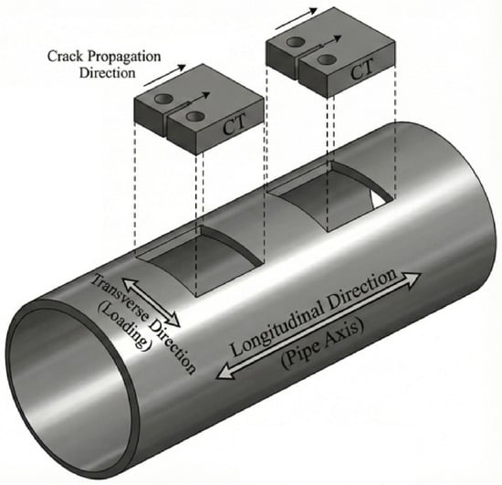
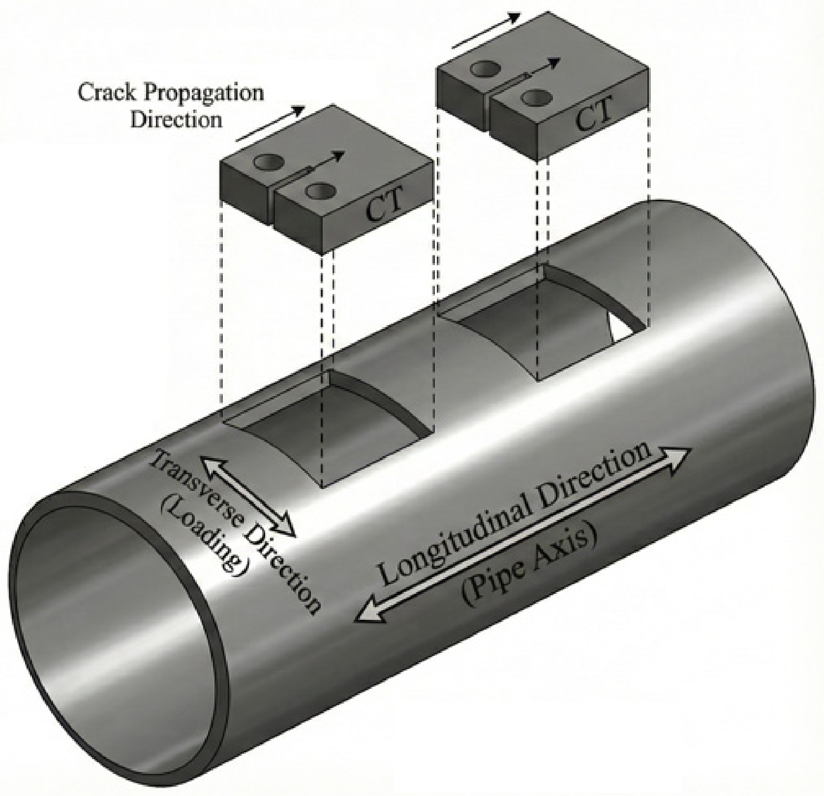
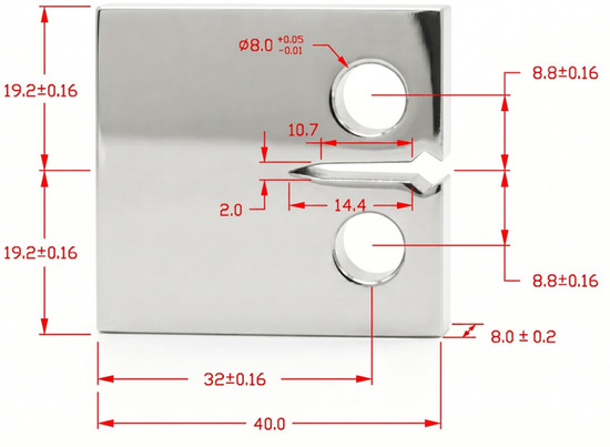
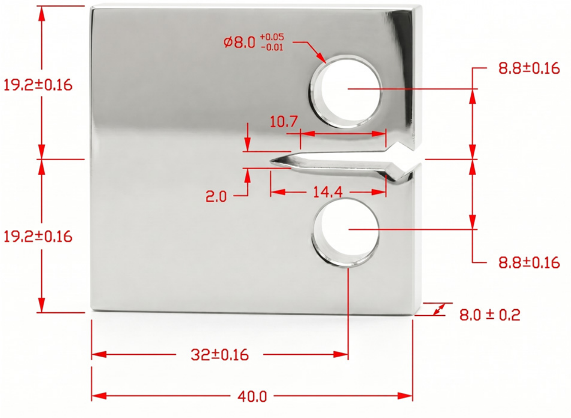
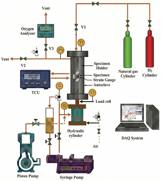
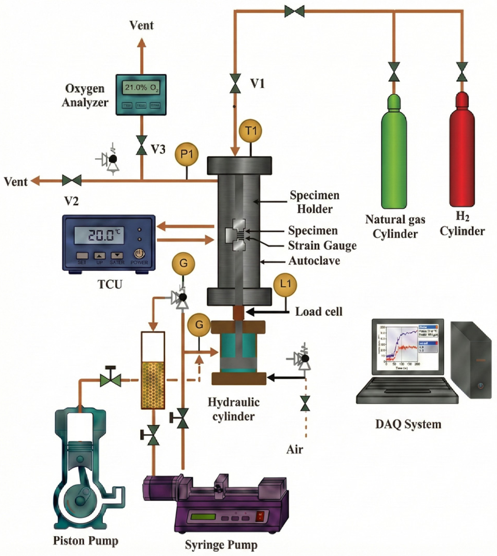
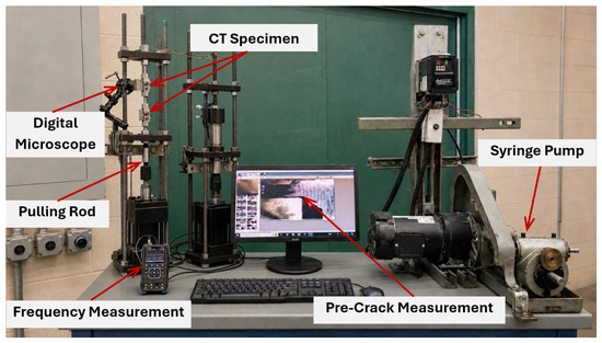
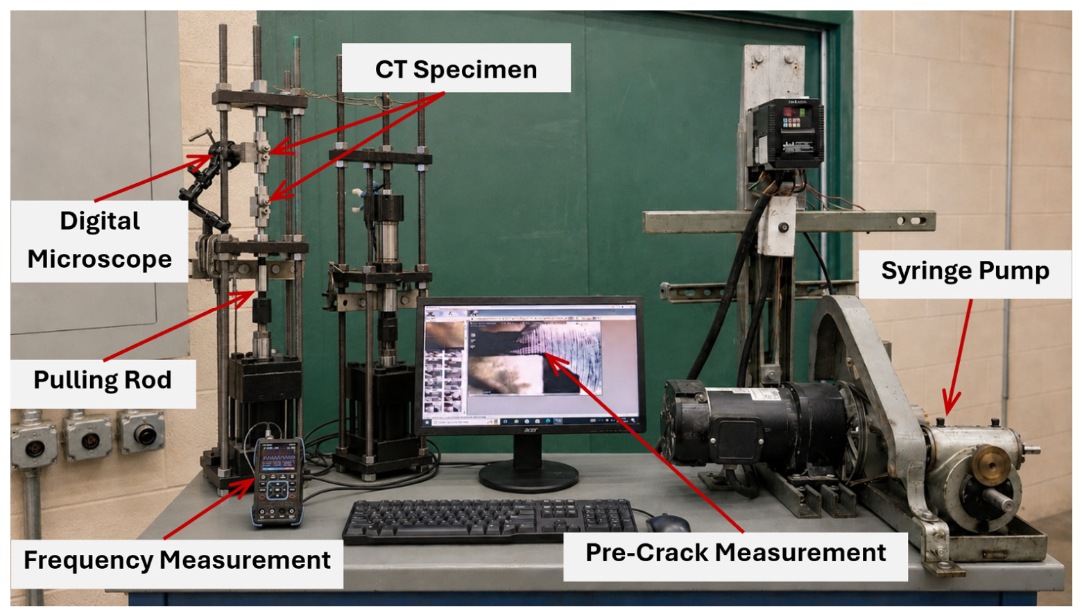
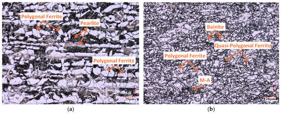
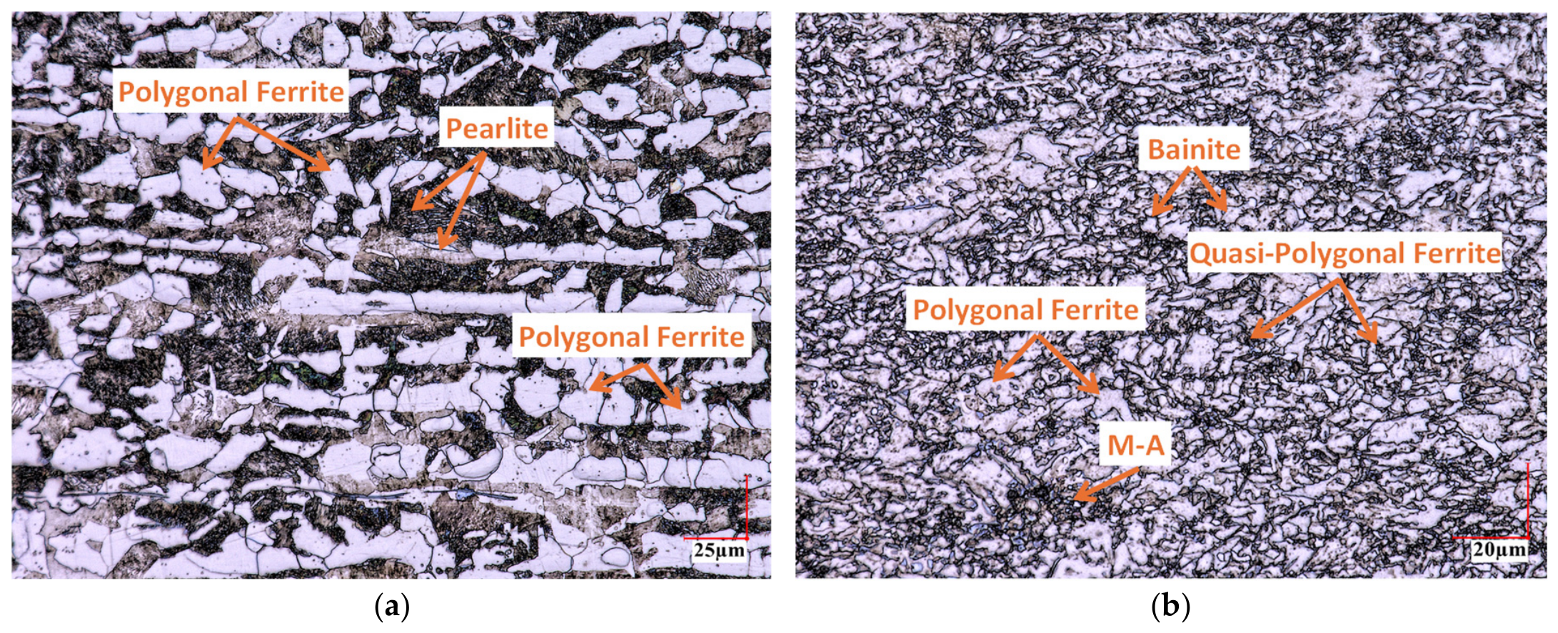
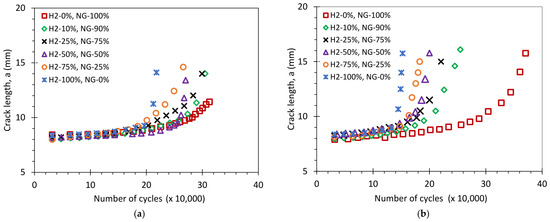
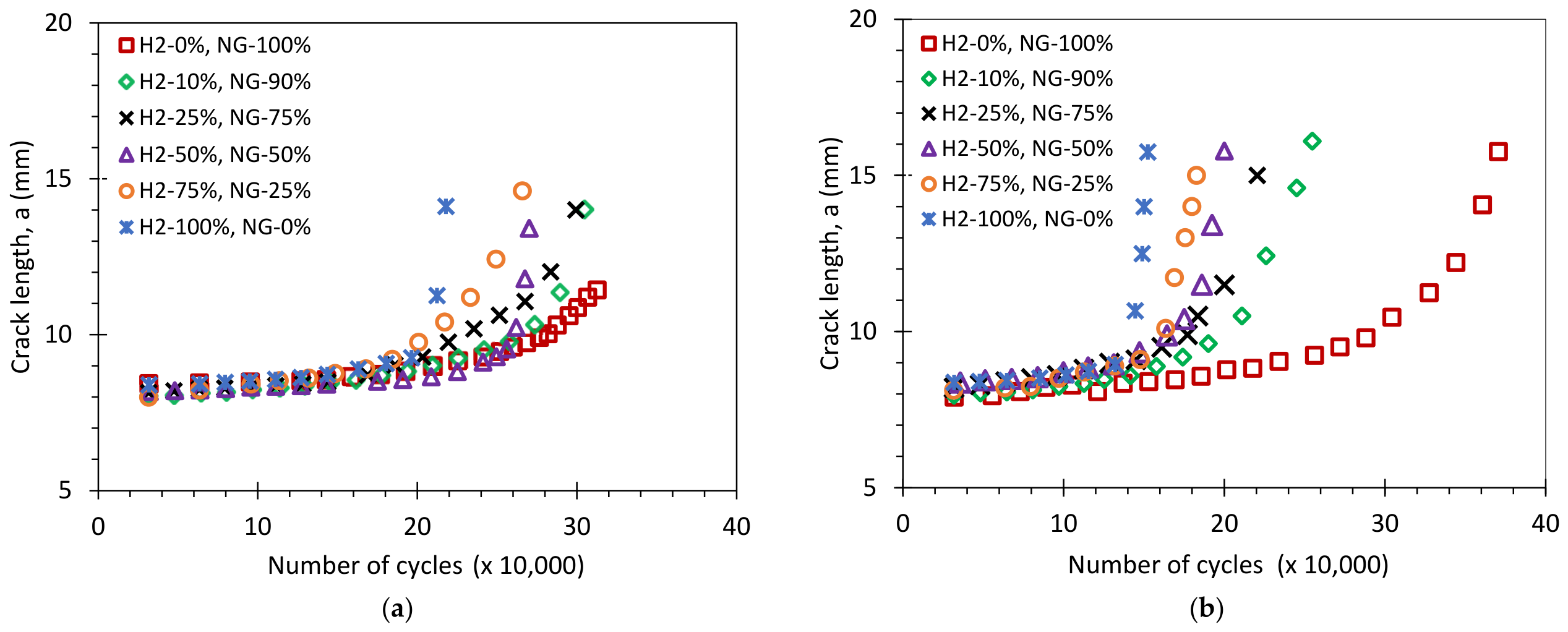
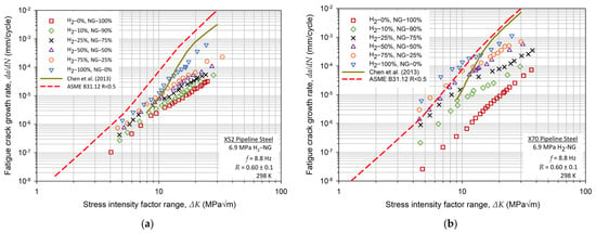
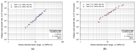
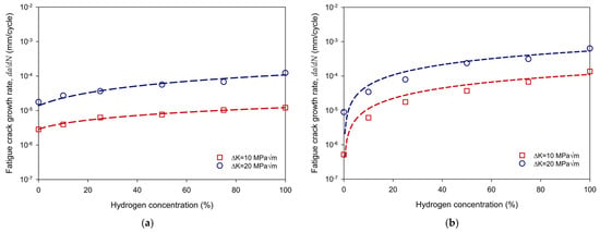
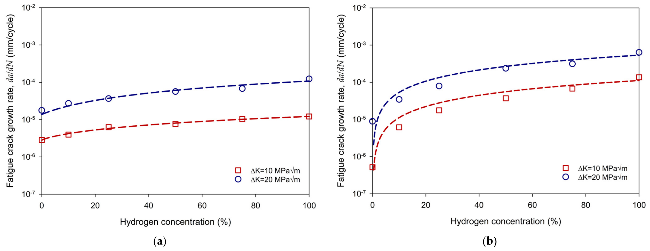
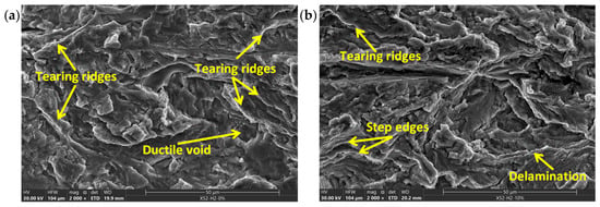
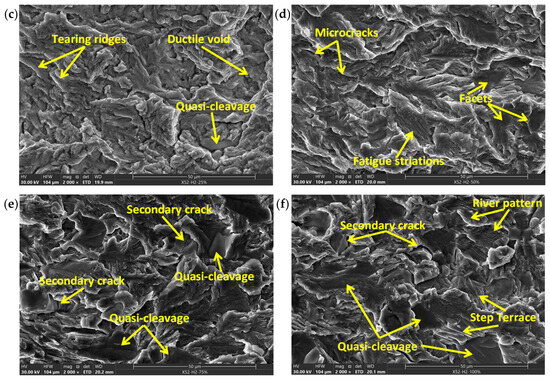
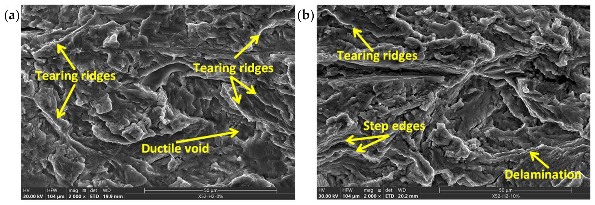
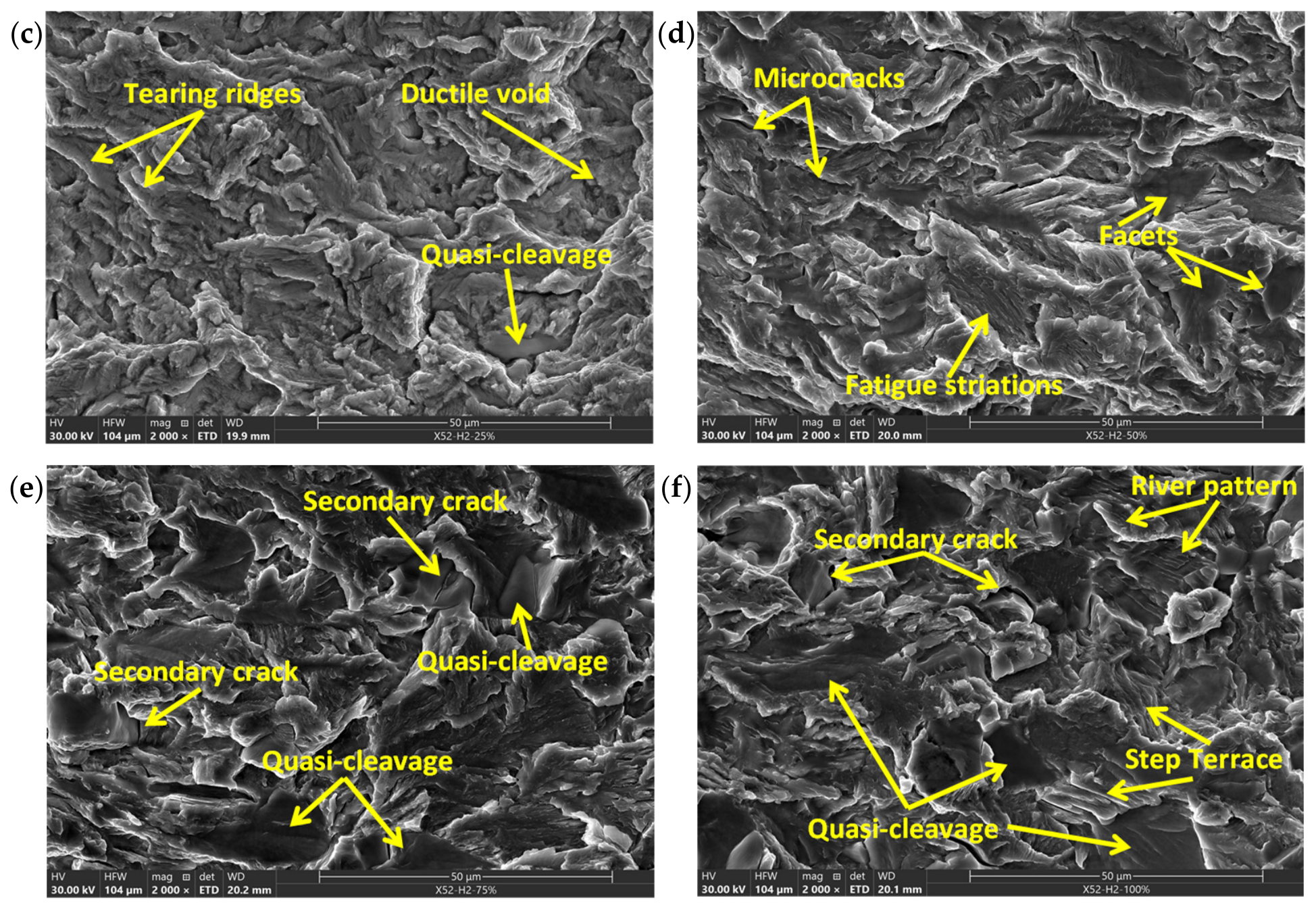
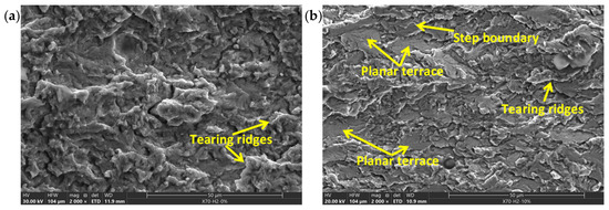
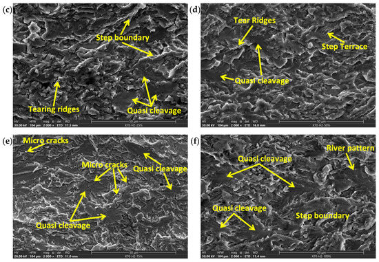
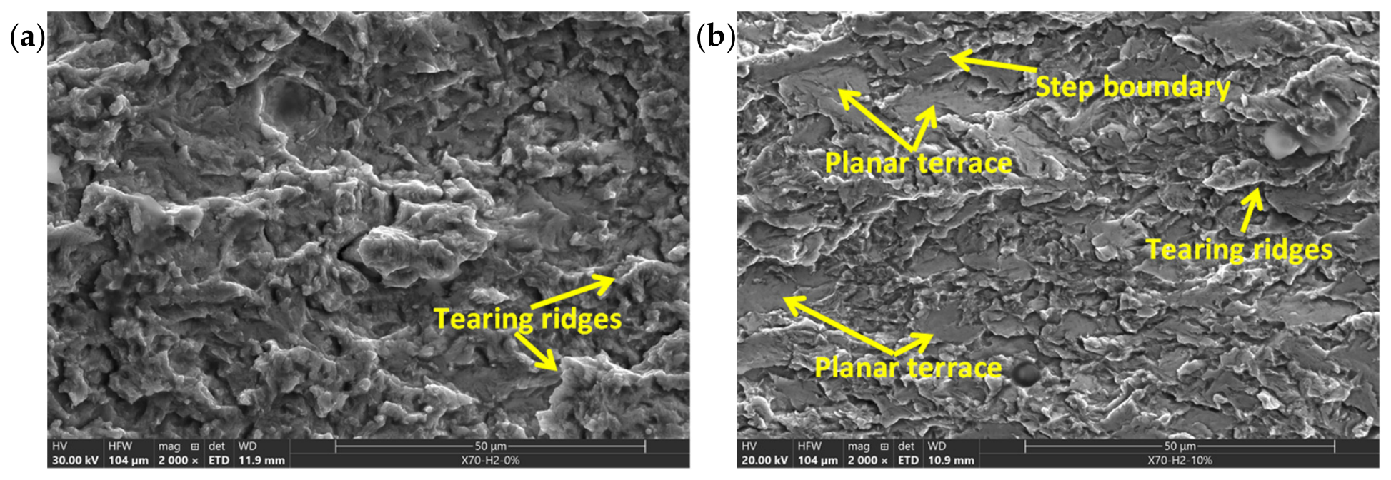
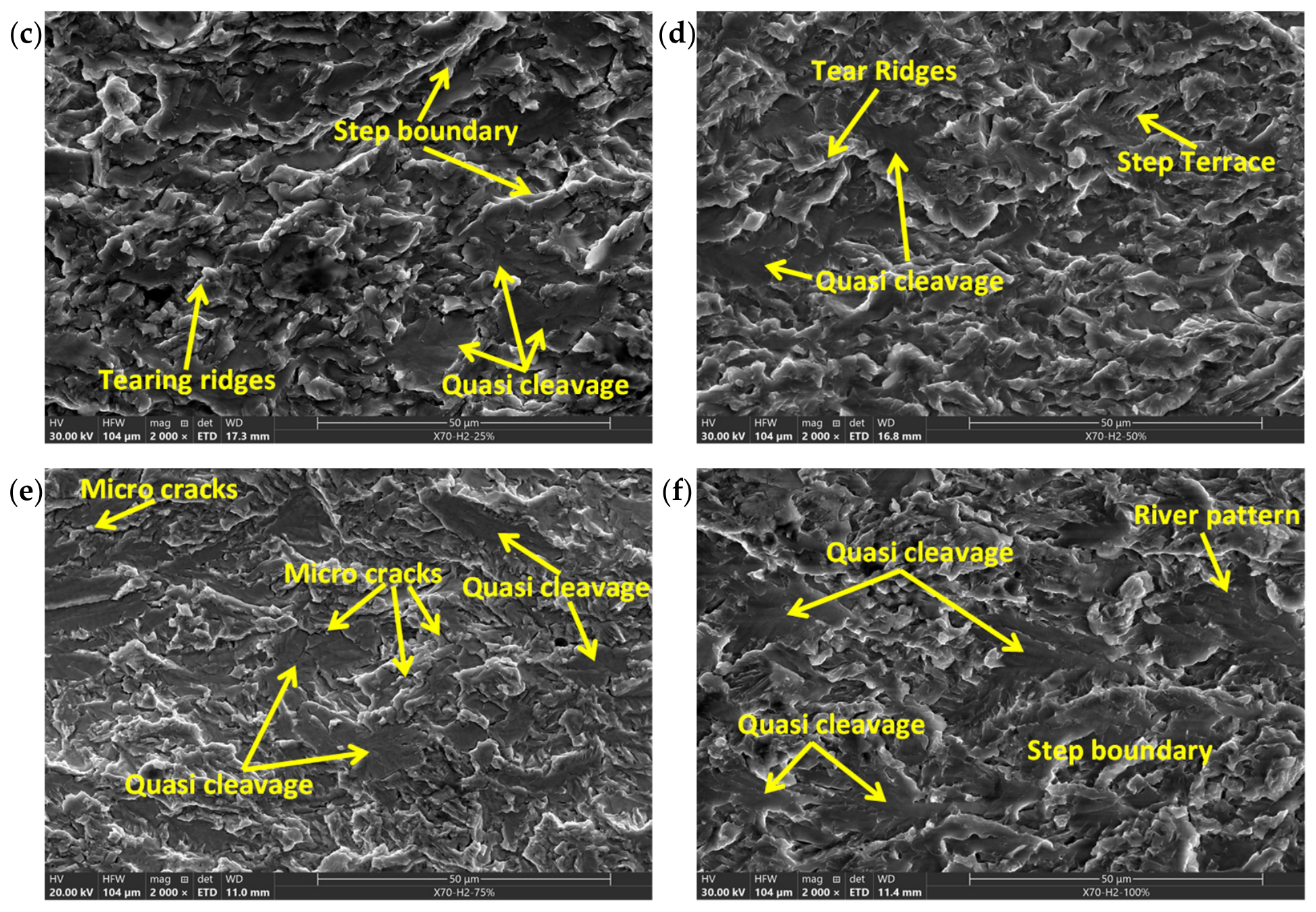

Disclaimer/Publisher’s Note: The statements, opinions and data contained in all publications are solely those of the individual author(s) and contributor(s) and not of MDPI and/or the editor(s). MDPI and/or the editor(s) disclaim responsibility for any injury to people or property resulting from any ideas, methods, instructions or products referred to in the content. |
© 2026 by the authors. Licensee MDPI, Basel, Switzerland. This article is an open access article distributed under the terms and conditions of the Creative Commons Attribution (CC BY) license.