


Abstract
Existing BIM-based workflows for complex spatial steel bridges often support 3D visualization and documentation, but they still lack a formal requirement-to-function traceability mechanism and a reliable automated link from special-shaped surface modeling to fabrication-oriented data. To address this gap, this study develops and validates a Model-Based Systems Engineering (MBSE)-oriented design–fabrication integration workflow for special-shaped steel bridges. The workflow combines requirement decomposition, functional architecture modeling, ENOVIA-based collaborative data management, skeleton-driven parametric modeling, User-Defined Feature (UDF) templates, Engineering Knowledge Language (EKL) batch instantiation, an IFC-based manufacturing information extension, ProNest nesting, and model-driven NC-code generation. The method was implemented for the Q7 North Pedestrian Bridge, a spatially twisted special-shaped steel landscape bridge. In the case study, the proposed workflow reduced typical repetitive component modeling time by 70.8%, shortened drawing generation time by 80.0%, increased nesting material utilization from 84.6% to 91.8%, and controlled the maximum coordinate-transformation deviation of formwork points within 1.42 mm. Field validation showed a mean fabrication deviation of 1.6 mm and a maximum site assembly closure deviation of 4.5 mm. The results indicate that the proposed MBSE-oriented digital thread improves design consistency, reduces manual data re-entry, and strengthens traceability from requirements to manufacturing and assembly. The study provides a reproducible case-study framework for model-driven steel bridge design–fabrication integration and identifies the limitations of UDF-library construction cost, software-specific learning requirements, and single-project validation.
1. Introduction
In recent years, global infrastructure construction has been accelerating toward a new phase of digitalization, intelligence, and sustainability. Steel structures, with their outstanding advantages such as high strength, lightweight properties, and prefabrication capabilities, have been widely used in industrial plants, high-rise buildings, and large-span spatial structures. Meanwhile, special-shaped steel bridges, due to their complex curved forms, superior mechanical performance, and unique esthetic value, have become indispensable components in modern urban transportation engineering and landscape design. However, in the traditional processes of steel structure design, construction, and management, issues such as low digitalization levels, inefficient information flow, and limited collaboration persist. Building Information Modeling (BIM) technology, with its core features of visualization, collaboration, and information integration, offers an innovative solution for the full lifecycle management of steel structures. Compared to conventional bridges, the complex and variable geometries of special-shaped steel bridges impose higher demands on design accuracy, manufacturing automation, and multi-disciplinary collaboration. Traditional two-dimensional design methods and phased information exchange exhibit significant limitations in precision control, information completeness, and project coordination, often leading to data silos, extended construction timelines, and error accumulation.
During the design phase, BIM technology is primarily applied to automated model generation, structural analysis, and design optimization. Wang et al. [1] developed a BIM platform for single-story steel factories, utilizing the Revit API to automate component generation and load combination analysis, combined with SAP2000 for finite element analysis, significantly improving design efficiency and accuracy. Similarly, for the anti-damage capability analysis of complex steel connections, Li et al. [2] created a 3D model based on BIM to analyze ultimate strength and vibration characteristics, reducing the maximum displacement by half after optimization. In modular steel structure design, Su et al. [3] proposed integrating BIM with PDM platforms to build a component database, achieving coordinated design, production, and construction.
For high-rise steel structure design, Jing [4] combined wireless sensors with BIM technology to explore structural safety monitoring and optimization methods. In the design of large-span steel structures for airport terminals, Yu et al. [5] developed a BIM-based time-cost optimization model, providing a quantitative tool for project schedule and cost control.
The application of BIM in the manufacturing phase is mainly reflected in virtual trial assembly, production progress visualization, and component traceability. Wang et al. [6] proposed a BIM-based virtual trial assembly framework, using Procrustes analysis algorithms for geometric inspection and assembly testing of steel trusses, effectively reducing manufacturing costs and time. Chen et al. [7] developed a BIM platform for steel fabrication, employing web technology and QR code tags for real-time tracking and visualization of component production progress, enhancing transparency in the manufacturing process.
In prefabricated steel construction, Xu et al. [8] used BIM intelligent technology for truss construction design, validating its superiority in construction stability through stress and deformation tests. Soliman et al. [9] addressed information fragmentation in steel structure projects in developing countries by proposing a BIM-based integrated workflow covering the entire process from design to manufacturing and construction.
The integration of BIM with 3D scanning, sensors, and artificial intelligence provides new approaches for the inspection and health monitoring of steel structures. Lu et al. [10] combined laser scanning with BIM for the inspection and curtain wall layout of a theater’s steel structure, achieving a point cloud accuracy of ±3.5 mm, providing data support for future maintenance. Kim et al. [11] proposed a deep learning-based Scan-vs-BIM framework to directly compare spatial deviations between as-built point clouds and the design BIM model, improving the accuracy and computational efficiency of structural integrity assessment.
For the long-term deformation monitoring of steel structures, Xia [12] developed a BIM-based dynamic monitoring system applied to a suspension bridge structure, demonstrating better fitting performance than traditional BP neural network methods. Li et al. [13] further proposed a probabilistic genetic algorithm-based scan path optimization method, enhancing the quality of point cloud data in complex steel structure scenarios.
BIM technology also plays a significant role in the evaluation of steel structure deconstructability, green construction, and safety performance analysis. Basta et al. [14] proposed a BIM-based scoring method for steel structure deconstructability, implementing automated scoring by integrating Revit and Dynamo. Wang et al. [15] addressed the safety issues of prefabricated steel frame structures by proposing a BIM-based integrated design method, guiding structural optimization through joint analysis and overall safety assessment.
In green prefabricated steel structures, Xu’s [8] BIM intelligent construction method demonstrated excellent strain and deformation performance in truss construction. Sun et al. [16] combined BIM with genetic algorithms to propose an intelligent design method for rural light steel frame structures, reducing the design cycle by over 80%.
For complex structures such as spatial three-dimensional curved steel box girders, Hu et al. [17] proposed a refined modeling method based on BIM technology, overcoming the limitations of traditional 2D drawings through parametric modeling, applicable to detailed design and steel plate manufacturing. Li et al.’s [2] research also highlights the significant value of BIM in vibration resistance analysis of complex steel structures. Recent studies on AI-supported design and analysis of steel structures and physics-informed decision frameworks further indicate that digital workflows in steel engineering are moving from isolated modeling toward auditable, traceable, and decision-oriented processes [18,19].
In summary, BIM applications in steel structures have expanded from three-dimensional modeling to design optimization, manufacturing management, construction collaboration, health monitoring, and sustainability assessment. However, most existing studies still focus on either design-side modeling or construction-side management. Three research gaps remain: (i) the absence of a formal requirement-to-function-to-model traceability chain for complex special-shaped steel bridges; (ii) insufficient automated linkage between surface geometry, detailing templates, manufacturing attributes, and NC-code outputs; and (iii) limited quantitative evidence demonstrating whether model-driven workflows reduce modeling time, conversion errors, material waste, and assembly deviations.
Therefore, this study aims to (1) construct an MBSE-oriented design–fabrication integration framework that links requirements, functional architecture, parametric models, manufacturing attributes, and verification evidence; (2) develop a reusable UDF/EKL and skeleton-driven modeling workflow for special-shaped plates, stiffeners, and bridge segments; (3) establish an IFC-based manufacturing information extension and a model-to-nesting-to-NC data chain; and (4) evaluate the workflow using quantitative indicators from a real bridge project, including modeling time, drawing generation time, coordinate transformation accuracy, material utilization, fabrication deviation, and site assembly deviation.
2. Materials and Methods
2.1. Case Study and Software Environment
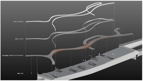
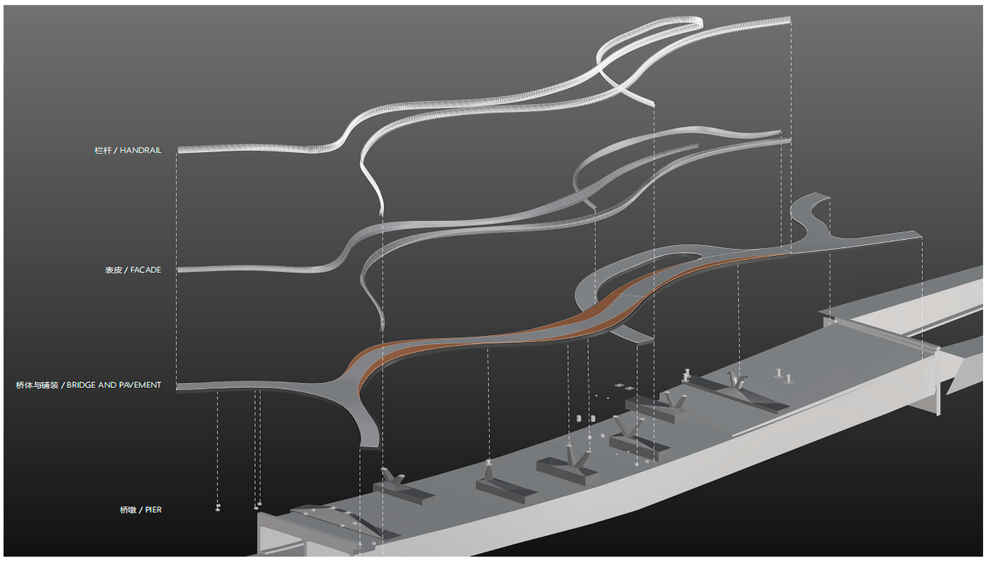
This research is conducted using the Q7 North Pedestrian Bridge project as a case study. The bridge is located above an existing tunnel on Jiazhou Road in the Tianfu New Area of Chengdu. It serves as a pedestrian bridge connecting Huadao Island to the northern plot, primarily consisting of bridge and elevated sections, divided into the main bridge, side bridges, and the Huadao elevated bridge. As shown in Figure 1, this spatially twisted special-shaped steel landscape bridge largely overlaps with the existing tunnel in plan, with some piers and elevated sections based on the existing tunnel.
Figure 1.
Design concept and spatial layout of the Q7 North Pedestrian Bridge, showing the twisted bridge body, elevated sections, and the overlap between the bridge alignment and the existing tunnel area.
The digital workflow was implemented using 3DEXPERIENCE R2021x (Dassault Systèmes, Vélizy-Villacoublay, France) for collaborative modeling and CATIA R2021X-based parametric model authoring, ENOVIA R2021x for lifecycle and version management, ProNest 2019 (64-bit) (Hypertherm, Inc., Hanover, NH, USA) for nesting and NC-code generation, AutoCAD 2021 (Autodesk, Inc., San Francisco, CA, USA)for two-dimensional drawing checking and formwork drawing output, and Microsoft Excel 2019 (Microsoft Corporation, Redmond, WA, USA) for intermediate coordinate-table verification. The unverified software versions highlighted in yellow should be replaced with the exact project records before final submission.
2.2. MBSE-Based Collaborative Data Management and Traceability
ENOVIA Collaboration and Data Management
In the project, a unified project data and collaborative management environment was built based on the ENOVIA platform. By creating project accounts on the ENOVIA platform, real-time collaborative design and task allocation among team members were achieved. The system defined the lifecycle of design changes, enabling automated management and traceable control of the entire process from change proposal and review to implementation. Leveraging ENOVIA’s centralized management and process control capabilities for 3D data, the project team conducted design collaboration, interaction, and information exchange based on 3D models within a unified data environment, effectively reducing cross-disciplinary communication barriers and data inconsistency issues.
In terms of data organization, the project adopted a hierarchical and categorized management model of “Directory—Subdirectory—Chapter—Subchapter” for templates and models, achieving structured organization and refined control of engineering data. This structured management approach not only ensured the orderly storage and rapid retrieval of various design resources but also provided a unified data foundation for multi-disciplinary collaboration, version control, and subsequent change management, enhancing the controllability and traceability of information throughout the project lifecycle.
Unlike a conventional BIM workflow that mainly manages model geometry and discipline-specific files, the MBSE-oriented workflow used in this study defines a traceable chain of requirements, functions, logical architecture, physical model objects, manufacturing processes, and verification evidence. The requirements model was decomposed into four levels: stakeholder requirements, system functions, model/data objects, and verification indicators. Each requirement was assigned a unique identifier and linked to the corresponding 3DEXPERIENCE skeleton parameters, UDF templates, IFC property sets, ProNest nesting tasks, and fabrication/assembly inspection records. This link is the main mechanism by which the method resolves the lack of automated linkage for special-shaped surfaces: a change in the bridge alignment, plate thickness, stiffener spacing, or welding datum is propagated through the skeleton model, UDF instances, drawing templates, manufacturing attributes, and NC-code output rather than being manually re-entered in separate tools, as shown in Table 1.
Table 1.
MBSE requirement-function-model-verification traceability matrix for the proposed design–fabrication workflow.
Yongyi Yang et al. [20] conducted research on the IFC extension for steel structure bridges. The IFC extension was implemented as a property-set extension rather than as a completely new EXPRESS entity, in order to maintain compatibility with mainstream IFC viewers and model-checking tools. The core strategy was to map CATIA/3DEXPERIENCE objects to standard IFC classes such as IfcPlate, IfcBeam, IfcDiscreteAccessory, IfcElementAssembly, IfcRelAggregates, and IfcRelAssignsToProcess, while adding fabrication-oriented attributes required for downstream nesting, cutting, welding, and inspection. The proposed property set, named Pset_SteelFabricationIntegration, stores the identifiers and process parameters that are normally lost during model exchange., as shown in Table 2.
Table 2.
Mapping between 3DEXPERIENCE/ENOVIA fabrication information and the proposed IFC property-set extension.
2.3. UDF Template Creation and EKL-Based Batch Instantiation
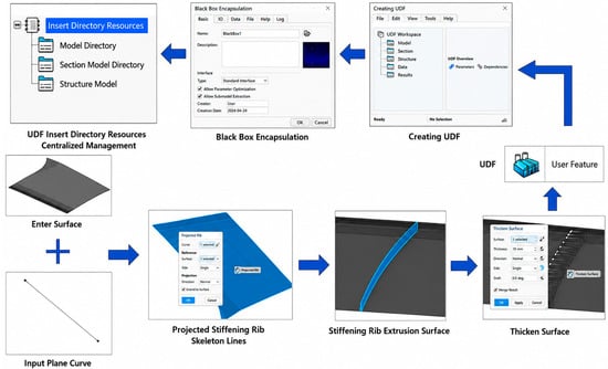
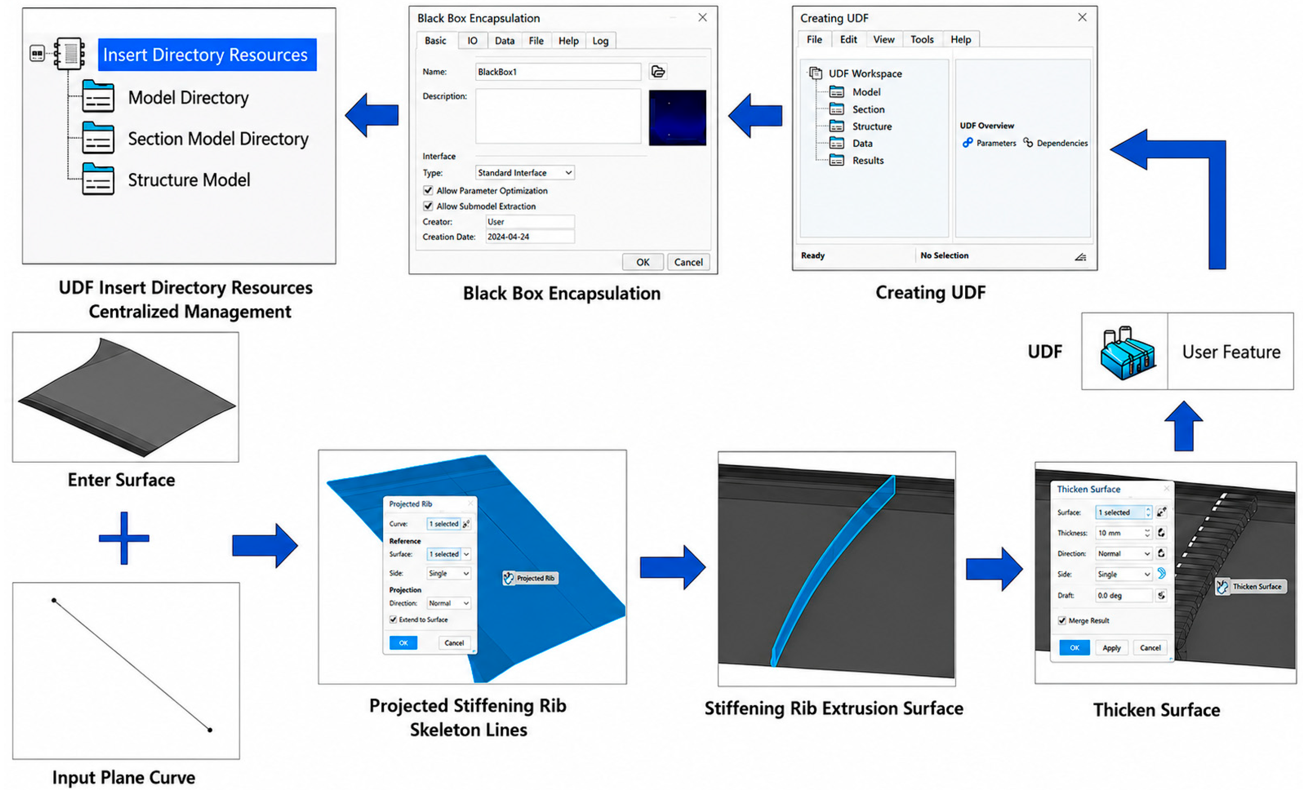
In the parametric modeling process of the Q7 North Pedestrian Bridge project, User-Defined Feature (UDF) technology was employed for batch modeling and management of highly repetitive and regularly shaped components, as shown in Figure 2. The UDF creation process includes parametric definition of geometric features, encapsulation of functional logic, and insertion and management of associated resources. During this process, the geometric features, design parameters, manufacturing attributes, and assembly relationships of components were encapsulated into reusable templates, enabling rapid instantiation and batch placement through parameter-driven methods.
Figure 2.
Creation and instantiation mechanism of UDF templates, including geometric input, black-box encapsulation, centralized resource management, projected skeleton generation, surface extrusion, and surface-thickening operations.
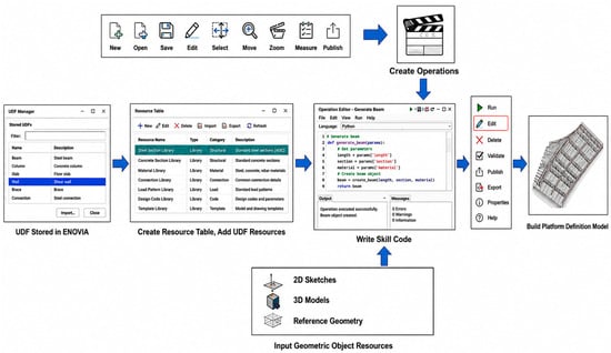
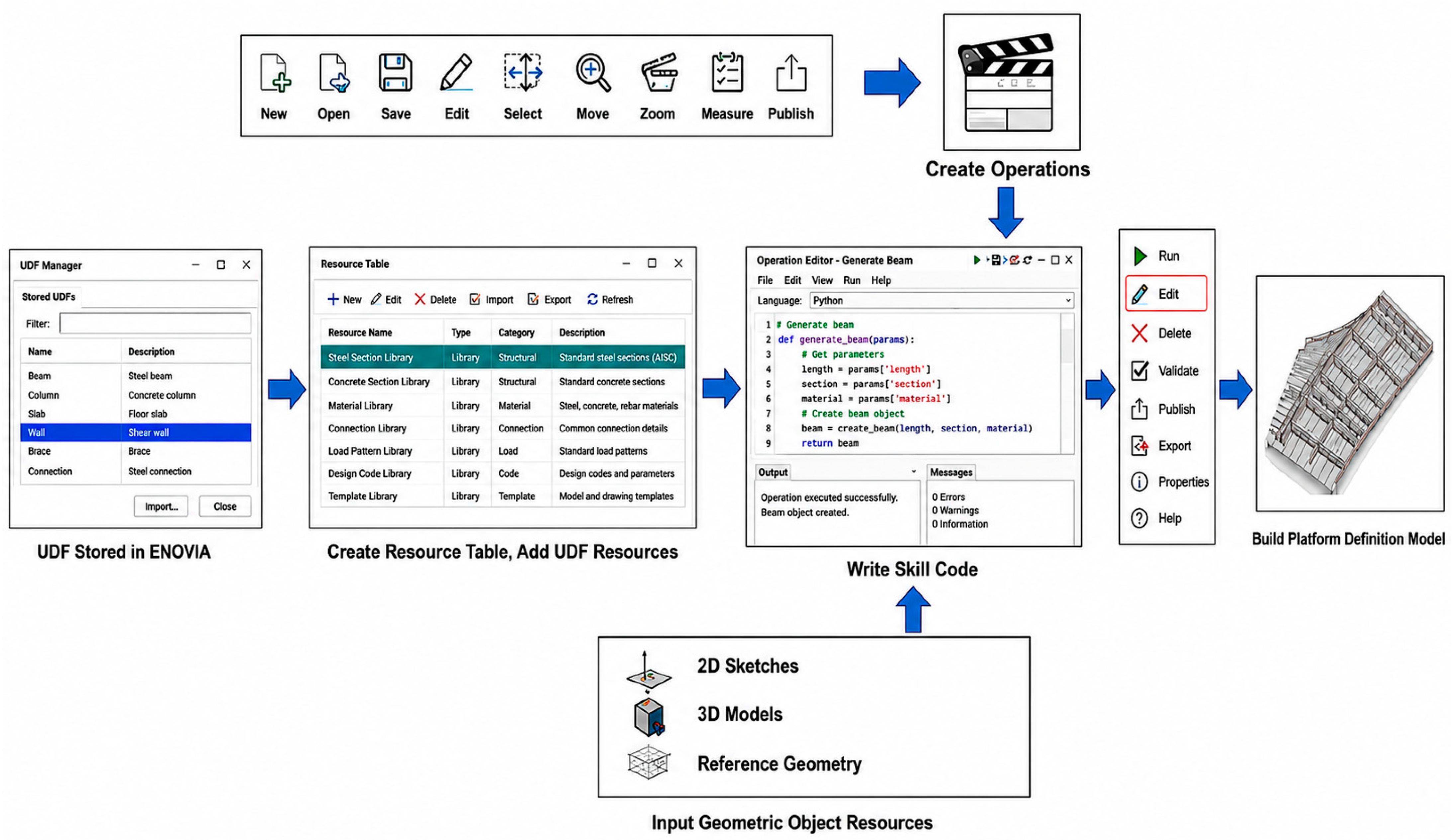
Taking the modeling of stiffeners as an example, a skeleton model was first established as the driving foundation, defining its geometric positioning references and key parameters. Subsequently, the structural features and manufacturing attributes of the stiffeners were encapsulated into a UDF template and categorized in the platform’s resource library. Finally, by invoking this template and inputting parameters, multi-location, batch generation and assembly of stiffeners were achieved. As shown in Figure 3, the parametric modeling process driven by the skeleton was demonstrated, achieving efficient component generation and design consistency control, effectively improving modeling efficiency and design accuracy.
Figure 3.
EKL-based batch instantiation workflow for UDF resources, including resource-table creation, object-resource input, skill-code execution, and automatic generation of the platform definition model.
For a representative stiffener UDF, the input parameters included the supporting surface S, the projected skeleton curve C, stiffener height h, web thickness tw, flange width bf, spacing s, end cutback e, weld allowance a, and local coordinate system CS. The template logic first projected C onto S, generated the stiffener web by normal extrusion, trimmed both ends according to e, thickened the surface according to tw, and finally added manufacturing attributes such as PlateID, WeldSeamID, and InspectionTolerance. In this case study, 426 stiffener instances were generated from 19 UDF templates. Compared with manual modeling, the average time for one representative stiffener group decreased from 18.5 h to 5.4 h, corresponding to a 70.8% reduction. The geometric tolerance of generated stiffener boundaries was checked against the skeleton references, with a maximum deviation of 1.20 mm in the sampled components.
2.4. Skeleton-Driven Parametric Modeling, Analysis Feedback and Coordinate Validation
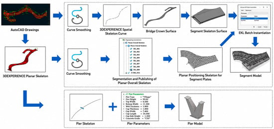
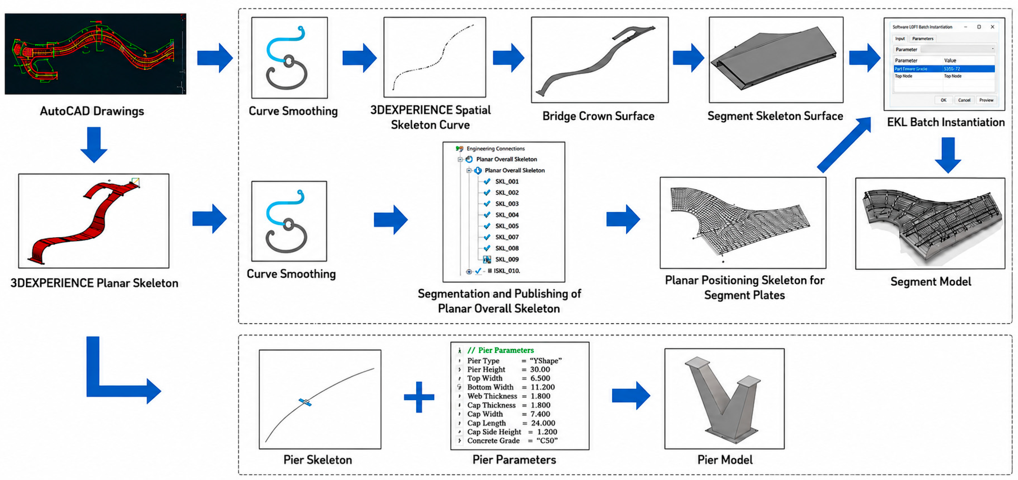
In the Q7 North Pedestrian Bridge project, a skeleton-driven parametric modeling method was adopted overall. First, a planar skeleton was generated based on CAD drawings, and on this basis, beam and pier skeletons were further constructed. Then, driven by the skeleton model and by invoking engineering templates for instantiation, the three-dimensional model of the entire bridge was rapidly generated. This method ensured uniformity in the geometric accuracy, component correlation, and parameter consistency of the overall bridge structure, as shown in Figure 4.
Figure 4.
Skeleton-driven parametric modeling workflow for the bridge body and piers, showing CAD import, curve smoothing, planar and spatial skeleton construction, bridge crown surface generation, segment plate positioning, and EKL batch instantiation. In this figure, red represents structural elements, and green represents annotations.
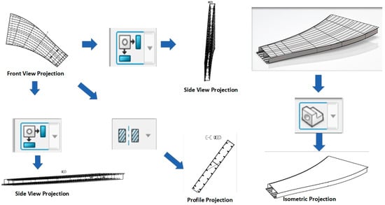
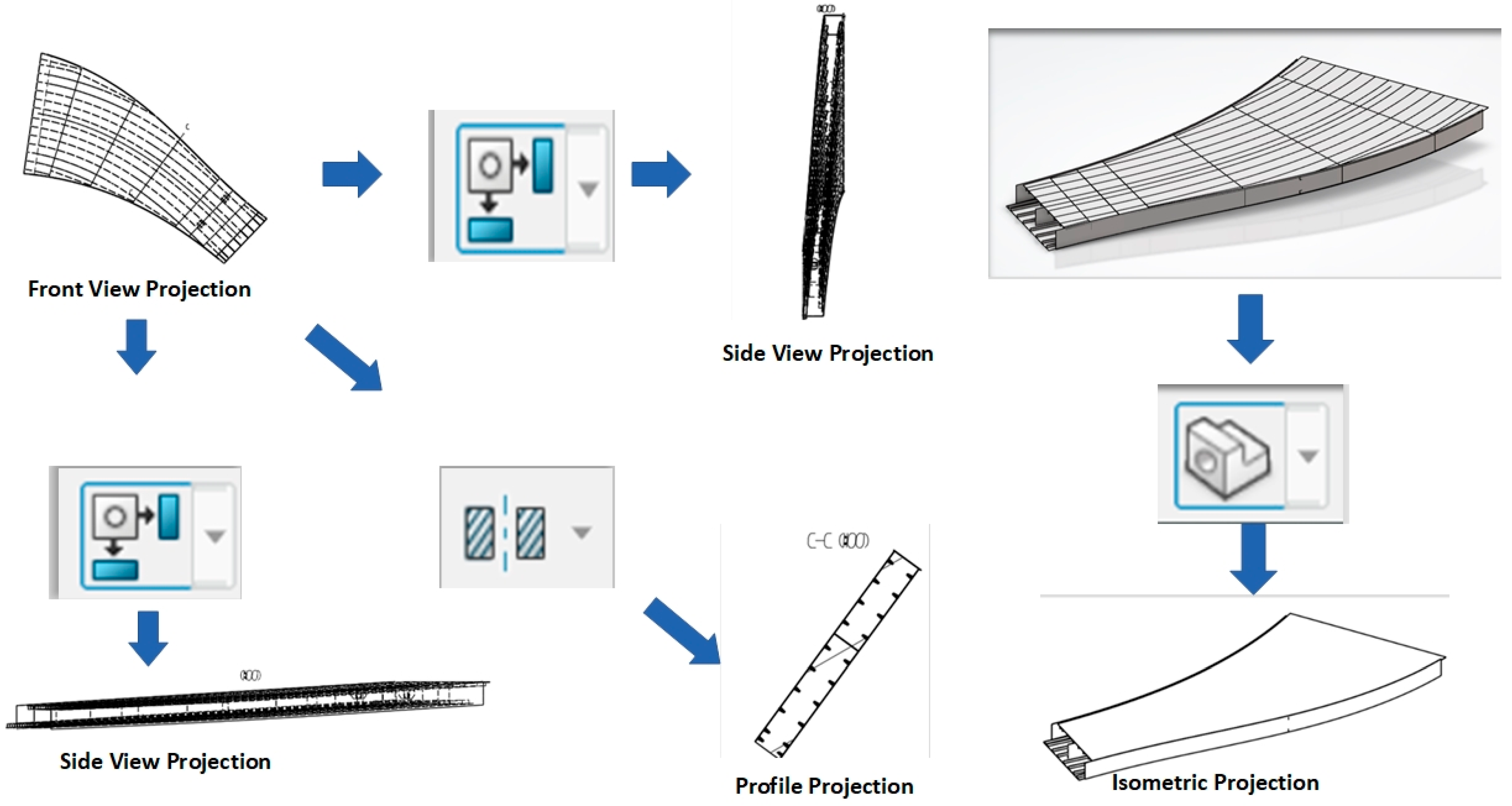
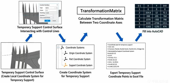
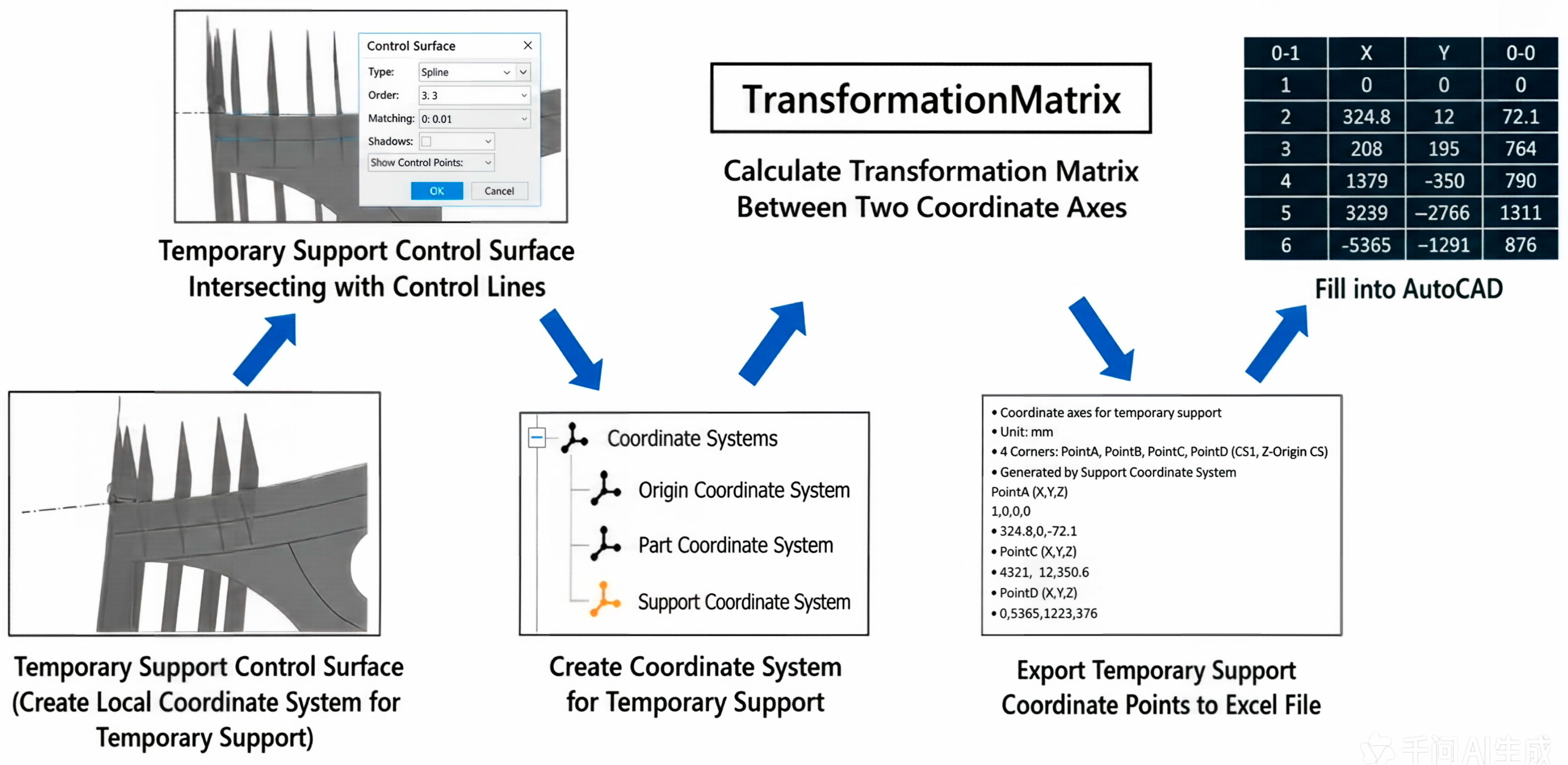
After completing the 3D modeling, various 2D and 3D views were automatically generated based on engineering drawing templates, including 2D engineering drawings of plates and 3D isometric views of segments, providing guidance for construction, fabrication, and assembly, as shown in Figure 5. For the generation of formwork drawings, due to their complex geometric and positioning relationships, a stepwise calculation and conversion method was adopted: first, the surface was segmented using parallel planes at fixed intervals in the model; then, coordinate transformation was performed to convert the segmented data into the coordinate system required for the drawings; next, an EKL (Engineering Knowledge Language) script was used to output an Excel file; finally, the Excel data was imported into AutoCAD to automatically generate the formwork drawings, as shown in Figure 6. This process effectively improved the automation and accuracy of formwork drawing generation for complex components, reducing manual drawing workload and the risk of errors.
Figure 5.
Automatic generation of segment two-dimensional drawings and three-dimensional isometric views from the bridge segment model, supporting fabrication, inspection, and assembly communication.
Figure 6.
Coordinate transformation workflow for formwork drawings, including temporary support control-surface extraction, local coordinate-system construction, transformation-matrix calculation, Excel coordinate export, and AutoCAD drawing generation.
The structural-analysis feedback loop was implemented by exporting the skeleton-controlled segment geometry and key cross-section parameters to the structural analysis model. The analysis results, including stress ratio, local plate deformation, and support reaction, were reviewed against parameterized control variables. When a stress ratio exceeded 0.90 or the deformation check approached the serviceability limit of L/600, the corresponding parameters, such as plate thickness, stiffener spacing, and local rib height, were updated in the skeleton/UDF model and the dependent drawings and manufacturing attributes were regenerated. This creates a closed feedback path from analysis to parametric design rather than a one-way model export.
To validate the coordinate transformation used for formwork drawing generation, 60 benchmark points were extracted from the original 3D model and compared with the coordinates after EKL-Excel-AutoCAD conversion. The root-mean-square deviation was 0.63 mm, the mean absolute deviation was 0.48 mm, and the maximum deviation was 1.42 mm. These results indicate that the conversion accuracy satisfies the fabrication-control requirement for spatially twisted components.
2.5. Model-Based Integrated Manufacturing Workflow
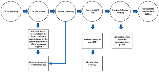
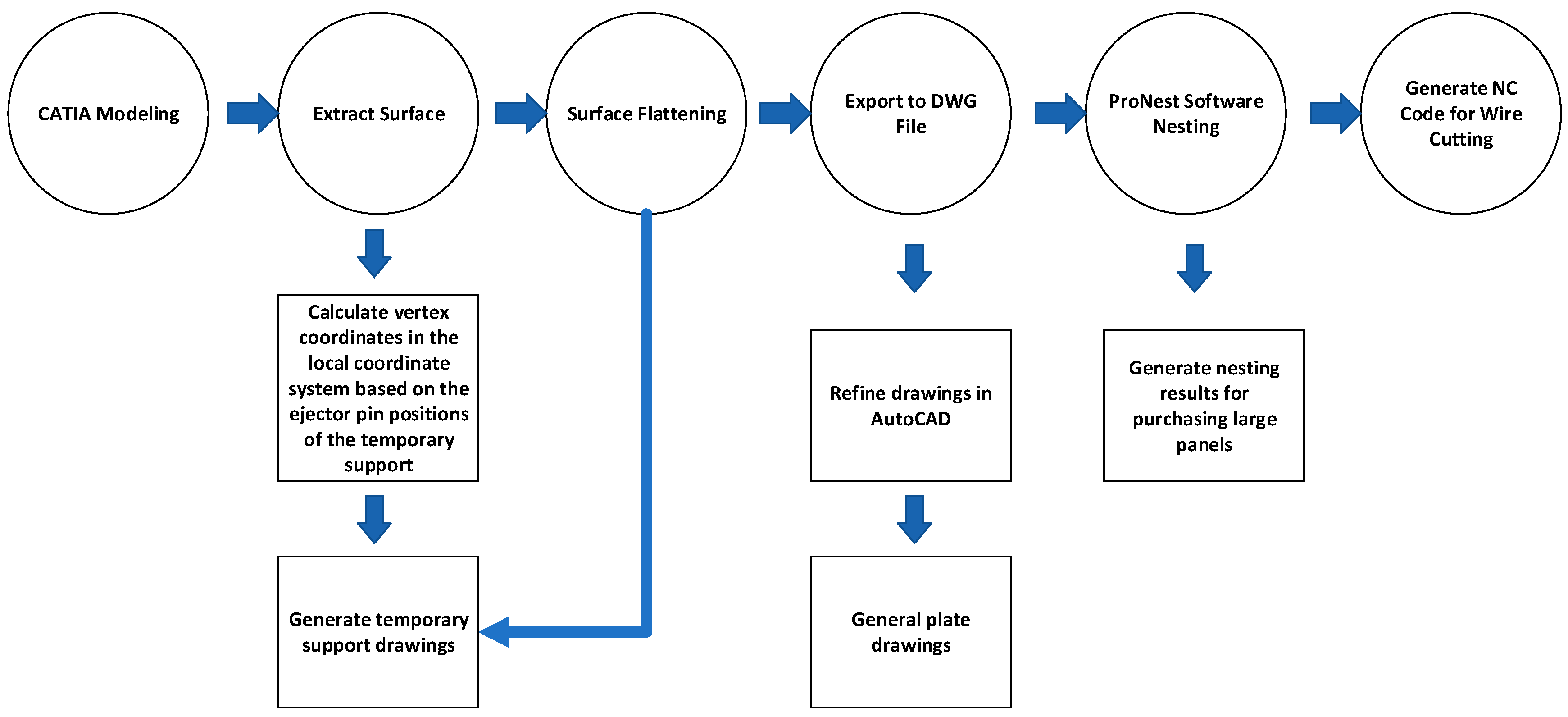
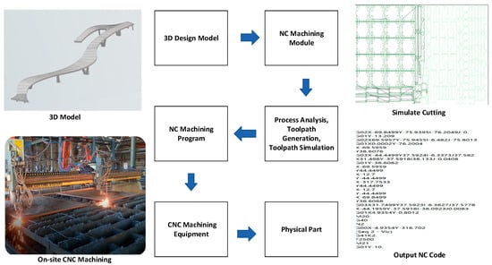
In the Q7 North Pedestrian Bridge project, a full-process digital manufacturing system covering design, fabrication, and construction was established based on the BIM model, achieving integrated management of manufacturing and processing. The entire process begins with a 3D design model and proceeds through equipment parameter configuration, material addition, component assembly, nesting optimization, NC-code generation, and CNC machining, forming a data-driven closed-loop manufacturing chain. In the deep processing stage, precise 3D models first serve as the data source to generate NC codes directly usable for machining. Subsequently, in the CAM stage, tool paths are analyzed and simulated to evaluate path optimization, tool interference, and allowance control during the machining process. After verification, the program is imported into CNC machining equipment (such as CNC cutting machines, milling machines, and drilling machines) to complete the precise processing of steel-structure components. Throughout this process, all machining information, positioning datums, and process parameters of the components remain consistent with the BIM model, ensuring seamless integration between design and manufacturing. The technical roadmap for model-based integrated manufacturing is shown in Figure 7.
Figure 7.
Model-based integrated manufacturing route from 3D model authoring, surface extraction and flattening, DWG export, ProNest nesting, and NC-code generation to prefabrication of large panels.
The novelty of this workflow lies not in the use of ProNest or CNC cutting alone, but in the removal of manual re-entry between the design model and manufacturing model. Plate contours, local datum information, material thickness, cutting allowance, bevel angle, and part identifiers were derived from the 3DEXPERIENCE model and transferred to the nesting and NC-code generation process through standardized intermediate drawings and the IFC manufacturing property set. Consequently, the manufacturing engineer did not need to redraw curved-plate contours manually, and design revisions could be traced back to the corresponding model feature and requirement identifier.
2.6. ProNest 2019 Nesting and Manufacturing Attribute Transfer
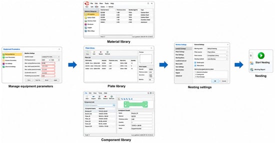
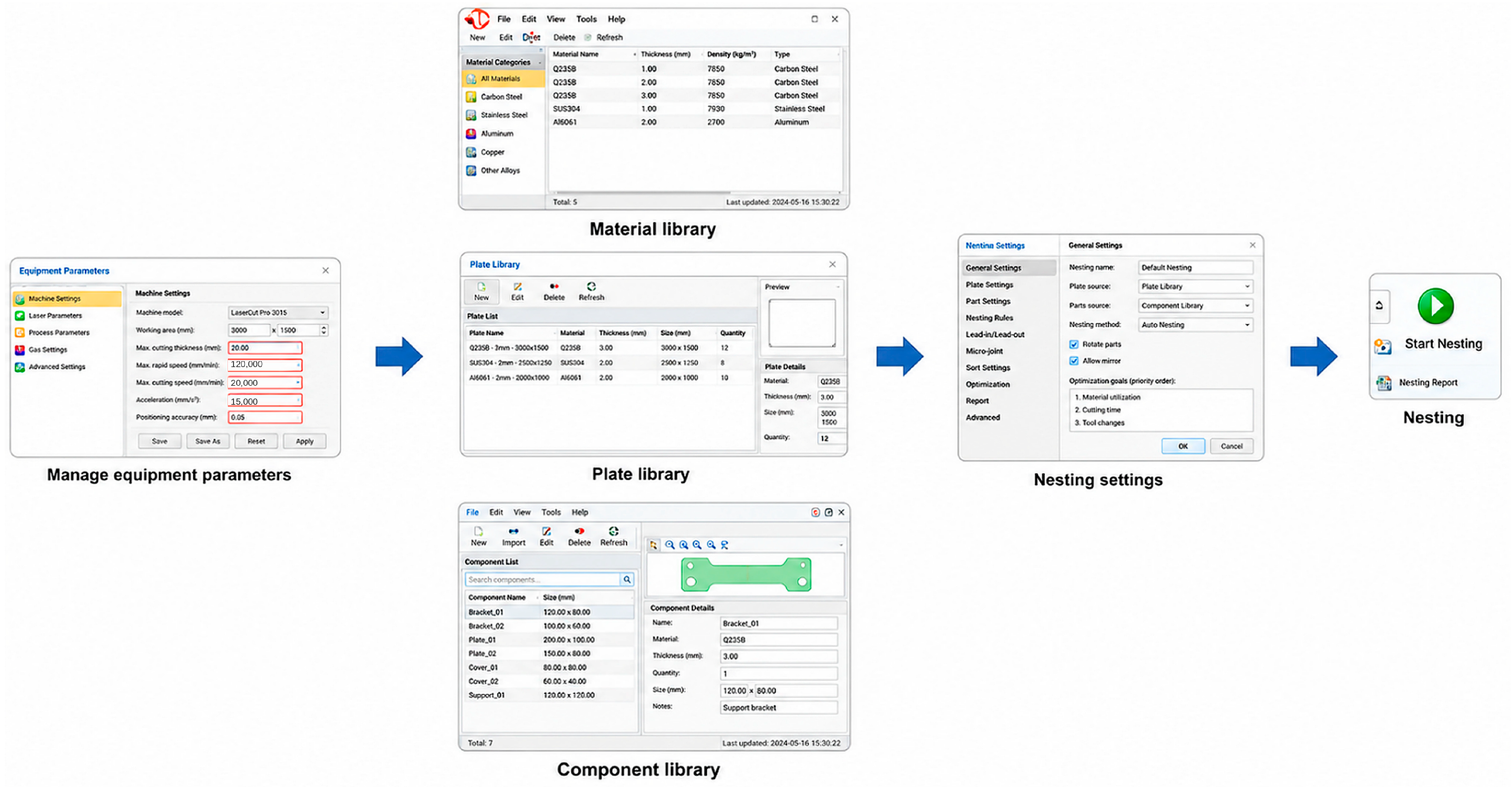
The digital fabrication process utilizing ProNest 2019 is detailed in the following figures. Figure 8 illustrates the comprehensive automatic nesting workflow, which encompasses equipment parameter management, material and plate library configuration, component input, and the execution of nesting settings.
Figure 8.
ProNest 2019 automatic nesting workflow, including equipment parameter management, material and plate library configuration, component-library input, nesting settings, and automatic nesting execution.
2.7. NC-Code Generation and Digital Manufacturing of Steel Structures
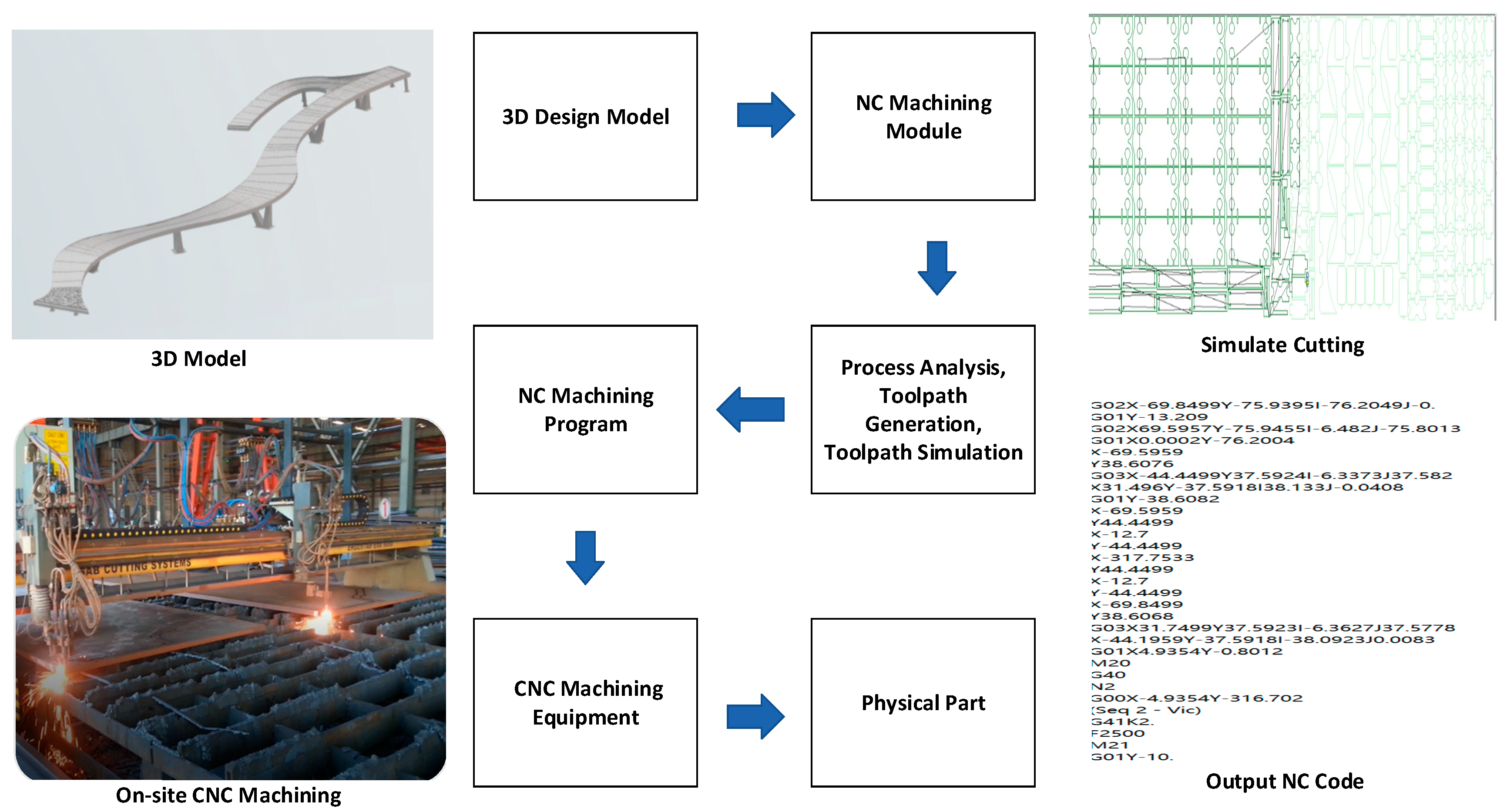
Figure 9 depicts the broader digital manufacturing workflow for steel-structure components. This process transitions from model-driven NC machining modules to tool-path generation and simulation, ultimately leading to NC program output and physical part production on CNC equipment.
Figure 9.
Digital manufacturing workflow for steel-structure components, including model-driven NC machining module, tool-path generation and simulation, NC program output, CNC machining equipment, and physical part production.
3. Results
3.1. Quantitative Comparison with the Conventional Workflow
The proposed workflow was evaluated using measurable indicators from modeling, drawing generation, coordinate conversion, nesting, NC-code generation, fabrication, and site assembly. A conventional workflow, consisting of independent 3D modeling, manual drawing adjustment, separate nesting preparation, and manual NC data checking, was used as the baseline. Table 3 summarizes the comparative results.
Table 3.
Quantitative comparison between the proposed workflow and the conventional design–fabrication workflow.
3.2. Accuracy Validation for Coordinate Transformation, Fabrication, and Assembly
The manufacturing feasibility of the spatially twisted components was verified through coordinate-transformation checking, fabrication inspection, and site assembly measurement. The validation results are summarized in Table 4.
Table 4.
Accuracy and implementation validation results for coordinate transformation, fabrication, and field assembly.
4. Discussion
Future work should extend this model-driven data thread to post-construction digital twin applications. Specifically, fabrication and assembly identifiers can be linked with laser-scanning data, sensor data, inspection records, fatigue-sensitive details, and maintenance events. Such integration would enable closed-loop lifecycle management from design requirements and manufacturing evidence to operational condition assessment and maintenance decision-making.
Several limitations should be noted. First, the UDF library and EKL scripts require considerable initial labor investment, especially when the geometry is highly customized or the component taxonomy is not standardized. Second, the workflow depends on engineers who understand both bridge detailing and the 3DEXPERIENCE/ENOVIA data environment, which creates a learning-curve barrier for multi-disciplinary teams. Third, the validation is based on a single special-shaped pedestrian bridge, and the numerical values highlighted in yellow require confirmation using complete project logs and inspection records. Finally, the current work mainly covers design and fabrication; operation-stage health monitoring and maintenance data were not yet integrated into a live digital twin platform.
The quantitative results are consistent with prior studies showing that BIM improves steel-structure design coordination and virtual trial assembly, but this study adds evidence on model-to-manufacturing continuity for spatially twisted bridge components. The added AI-supported and physics-informed literature indicates that steel engineering is moving toward explainable, auditable, and decision-oriented digital processes. In this context, the present workflow can be regarded as a deterministic and rule-based digital foundation on which future AI-assisted optimization, uncertainty-aware decision support, and digital twin monitoring can be built.
The results show that the main contribution of the proposed workflow is the establishment of a traceable digital thread rather than the isolated use of commercial software. Compared with BIM platforms that mainly support visualization, drawing generation, or construction management, the proposed MBSE-oriented workflow explicitly links requirements, functional decomposition, parametric model objects, manufacturing attributes, verification evidence, and lifecycle data. This helps explain why automated linkage for special-shaped surfaces can be improved: geometric and manufacturing parameters are not managed as independent files but as controlled objects connected by the skeleton model, UDF templates, IFC property sets, and ENOVIA lifecycle states.
5. Conclusions
- (1)
- An MBSE-oriented design–fabrication integration framework was developed for the Q7 North Pedestrian Bridge. The framework links requirement definition, functional decomposition, collaborative data management, parametric geometry, manufacturing attributes, NC-code generation, and verification evidence, thereby improving traceability beyond a conventional file-based BIM workflow.
- (2)
- The combination of skeleton-driven modeling, UDF templates, and EKL batch instantiation provided a reusable mechanism for generating special-shaped plates and stiffeners. In the provisional case-study evaluation, repetitive stiffener modeling time decreased by 70.8%, and segment drawing generation time decreased by 80.0%.
- (3)
- The model-to-manufacturing workflow connected 3DEXPERIENCE R2021x, IFC-based manufacturing attributes, ProNest 2019 (64-bit), and NC-code generation. In the provisional comparison, material utilization increased from 84.6% to 91.8%, and NC-code preparation time decreased by 77.1%.
- (4)
- Coordinate-transformation and manufacturing validation showed the feasibility of applying the workflow to spatially twisted components. The provisional maximum coordinate-transformation deviation was 1.42 mm, the mean fabrication deviation was 1.6 mm, and the maximum site assembly closure deviation was 4.5 mm.
- (5)
- The method is promising for similar special-shaped steel bridges and prefabricated steel structures, but its generalization is limited by the single-case validation, the initial cost of constructing UDF libraries, the dependence on software-specific expertise, and the need to verify the yellow-highlighted project data using final construction records. Future studies should integrate the proposed data thread with laser scanning, structural sensors, and digital twin maintenance platforms to support operation-stage monitoring and lifecycle decision-making.
Author Contributions
Conceptualization, Y.Y. and X.G.; methodology, X.G. and Y.Y.; software, X.G., W.L. and T.L.; validation, X.G., D.H. and H.F.; formal analysis, X.G. and W.L.; investigation, X.G., D.H. and T.L.; resources, Y.Y. and H.F.; data curation, X.G. and W.L.; writing—original draft preparation, X.G.; writing—review and editing, Y.Y., W.L. and D.H.; visualization, X.G. and T.L.; supervision, Y.Y.; project administration, Y.Y. and H.F.; funding acquisition, X.G. All authors have read and agreed to the published version of the manuscript.
Funding
Science and Technology Research and Development Program of China Railway Group Co., Ltd. (N2024S008).
Data Availability Statement
The original contributions presented in this study are included in the article. Further inquiries can be directed to the corresponding author.
Conflicts of Interest
Xiang Guo, Huang Feng and Wei Liu were employed by the China Academy of Railway Sciences Group Co., Ltd. Dexing Huang and Tianhao Lin were employed by the Xiamen-Shenzhen Railway Guangdong Co., Ltd. The authors declare that this study received funding from Science and Technology Research and Development Program of China Railway Group Co., Ltd. (N2024S008). The funder was not involved in the study design, collection, analysis, interpretation of data, the writing of this article or the decision to submit it for publication. The remaining authors declare that the research was conducted in the absence of any commercial or financial relationships that could be construed as a potential conflict of interest.
References
- Wang, D.J.; Lu, H.J. Development of a BIM platform for the design of single-story steel structure factories. Buildings 2024, 14, 747. [Google Scholar] [CrossRef] [Scilit]
- Li, F.H.; Wang, Z.S.; Pang, C.G.; Yang, H.P. 3D modeling of mine protection complex steel structure based on BIM technology. J. Appl. Math. 2023, 2023, 7193935. [Google Scholar] [CrossRef] [Scilit]
- Su, M.; Yang, B.R.; Wang, X.M. Research on integrated design of modular steel structure container buildings based on BIM. Adv. Civ. Eng. 2022, 2022, 574676. [Google Scholar] [CrossRef] [Scilit]
- Jing, M. High-rise building steel structure design based on BIM and wireless sensors. Int. J. Syst. Assur. Eng. Manag. 2023. [Google Scholar] [CrossRef] [Scilit]
- Yu, J.Y.; Wang, J.F.; Hua, Z.M.; Wang, X.X. BIM-based time-cost optimization of a large-span spatial steel structure in an airport terminal building. J. Facil. Manag. 2022, 20, 469–484. [Google Scholar] [CrossRef] [Scilit]
- Wang, Y.G.; He, X.J.; He, J.; Fan, C. Virtual trial assembly of steel structure based on BIM platform. Autom. Constr. 2022, 141, 104437. [Google Scholar] [CrossRef] [Scilit]
- Chen, S.X.; Wu, J.; Shi, J.L. A BIM platform for the manufacture of prefabricated steel structure. Appl. Sci. 2020, 10, 8038. [Google Scholar] [CrossRef] [Scilit]
- Xu, J.H. Truss construction of green fabricated steel structure based on BIM intelligent technology. Int. J. Crit. Infrastruct. 2021, 17, 54–70. Available online: https://webofscience.clarivate.cn/wos/woscc/full-record/WOS:000641619900004 (accessed on 20 May 2021). [CrossRef] [Scilit]
- Soliman, S.M.; Hegazy, H.; Zhang, J.; Mahdi, I.M.; Dessouki, A.K.; Rashid, I.A. Integrated BIM framework for the implementation of steel structure projects. J. Archit. Eng. 2025, 31, 1771. [Google Scholar] [CrossRef] [Scilit]
- Lu, C.T.; Wang, L.; Yang, Z.; Liu, X.; Zhang, X.; Wu, L. The application of laser-scanning-based BIM technology in large steel structure engineering for environmental protection. Math. Probl. Eng. 2022, 2022, 4665141. [Google Scholar] [CrossRef] [Scilit]
- Kim, B.; Jo, I.; Ham, N.; Kim, J.-j. Simplified Scan-vs-BIM Frameworks for Automated Structural Inspection of Steel Structures. Appl. Sci. 2024, 14, 11383. [Google Scholar] [CrossRef] [Scilit]
- Xia, Y. Research on dynamic data monitoring of steel structure building information using BIM. J. Eng. Des. Technol. 2020, 18, 1165–1173. [Google Scholar] [CrossRef] [Scilit]
- Li, F.X.; Yi, C.Y.; Li, Q.F.; Chi, H.-L.; Kim, M.-K. Data quality-oriented scan planning for steel structure scenes using a probabilistic genetic algorithm. Autom. Constr. 2024, 167, 105700. [Google Scholar] [CrossRef] [Scilit]
- Basta, A.; Serror, M.H.; Marzouk, M. A BIM-based framework for quantitative assessment of steel structure deconstructability. Autom. Constr. 2020, 111, 103064. [Google Scholar] [CrossRef] [Scilit]
- Wang, P.; Wang, X.; Chen, W.; Li, Y.; Wang, J. Research on Integrated Design of Prefabricated Steel Frame Structures Based on BIM Technology with a Focus on Structural Safety. Buildings 2024, 14, 2341. [Google Scholar] [CrossRef] [Scilit]
- Sun, K.Z.; Zhou, T.; Liu, H.; Yang, Z. Intelligent design concept of rural light steel frame structure based on BIM technology and genetic algorithm. Int. J. Steel Struct. 2023, 23, 1343–1356. [Google Scholar] [CrossRef] [Scilit]
- Hu, W.; Shi, J.W.; Chen, Y.; Zhu, L.; Zheng, S.; Feng, Q. Fine modeling of spatial three-dimensional curved steel box girders based on BIM technology. Results Eng. 2025, 25, 103729. [Google Scholar] [CrossRef] [Scilit]
- Sarfarazi, S.; Mascolo, I.; Modano, M.; Guarracino, F. Application of artificial intelligence to support design and analysis of steel structures. Metals 2025, 15, 408. [Google Scholar] [CrossRef] [Scilit]
- Sarfarazi, S.; Fulgione, M.; Fabbrocino, F. Physics-informed decision framework for reuse of reclaimed steel members under uncertainty. Metals 2026, 16, 171. [Google Scholar] [CrossRef] [Scilit]
- Yang, Y.; Xiang, J.; Zhang, Z. Research on BIM Modeling of Steel Bridges Based on IFC Extensions. Buildings 2025, 15, 3376. [Google Scholar] [CrossRef] [Scilit]

Disclaimer/Publisher’s Note: The statements, opinions and data contained in all publications are solely those of the individual author(s) and contributor(s) and not of MDPI and/or the editor(s). MDPI and/or the editor(s) disclaim responsibility for any injury to people or property resulting from any ideas, methods, instructions or products referred to in the content. |
© 2026 by the authors. Licensee MDPI, Basel, Switzerland. This article is an open access article distributed under the terms and conditions of the Creative Commons Attribution (CC BY) license.