Article

DEM-FEM Coupling Simulation of Residual Stress Improvement for Q235B Welded Joint via Shot Peening

1
School of Intelligent Manufacturing, Kaifeng University, Kaifeng 475004, China
2
School of Mechanical and Power Engineering, Zhengzhou University, Zhengzhou 450001, China
*
Author to whom correspondence should be addressed.
Metals 2026, 16(7), 811; https://doi.org/10.3390/met16070811
Submission received: 12 June 2026 / Revised: 8 July 2026 / Accepted: 13 July 2026 / Published: 21 July 2026

Abstract

To overcome the welding-induced residual tensile stress of Q235B welded joints, a sequential thermal-mechanical welding and DEM-FEM dynamic shot peening coupled model is established. The Goldak double-ellipsoidal heat source model is adopted to simulate welding temperature evolution, and the discrete element method fully considers random shot ejection and shot–shot collision energy attenuation, which addresses the simplification defect of traditional single-shot finite element models. The effects of shot diameter d, incident angle θ, initial shot velocity v and mass flow rate rm on the residual compressive stress layer are systematically analyzed. Results reveal that larger shot diameter and initial shot velocity deepen the residual compressive stress layer. Meanwhile, the maximum residual compressive stress first increases and then decreases with the increase in rm and θ. The optimal parameter combination is determined as d = 1 mm, θ = 60°, v = 60 m/s, rm = 9 kg/min. Under these parameters, the maximum residual compressive stresses reach −306 MPa (σx) and −310 MPa (σz), with the depths of the residual compressive stress layer being up to 0.78 mm for σx and up to 0.66 mm for σz, respectively. Different from previous simplified simulations, this study quantifies the collision energy attenuation caused by shot trajectory overlap. This proposed model can provide guidance for post-weld surface strengthening of low-carbon steel engineering structures.

1. Introduction

Welded joints are widely used in engineering machinery, rail transportation, marine engineering, and other industrial fields. Severe and non-uniform thermal cycles during welding inevitably induce high residual tensile stress in welded joints, which easily causes crack initiation and propagation, and further significantly degrades mechanical properties and fatigue strength [1,2,3]. Therefore, improving the residual stress field of welded joints is of great engineering importance. Shot peening, as a cost-effective and efficient surface strengthening technology, can eliminate residual tensile stress and introduce residual compressive stress by means of high-velocity shot impact. It has been proven to be an effective post-weld treatment for improving mechanical properties and enhancing the fatigue strength of welded joints [4,5,6,7].
In recent years, extensive experimental studies have been conducted on residual stress improvement for welding joints via shot peening. To enhance the mechanical properties of laser-welded austenitic stainless steel 304, Meguehout et al. [8] experimentally studied the residual stress field in laser-welded AISI 304 joints after ultrasonic shot peening. The results showed that ultrasonic shot peening introduced high residual compressive stress on the surface, transforming the as-welded residual tensile stress into a residual compressive state. The magnitude of residual compressive stress increased with peening intensity, thereby enhancing the mechanical properties and fatigue strength of welded joints. Ralls et al. [9] experimentally explored the effect of shot peening coverage on the residual stress field and on the stress corrosion cracking behavior of austenitic stainless steel welds. Their results showed that shot peening effectively transformed surface residual tensile stress into residual compressive stress. With the increase in shot peening coverage from 100% to 500%, the magnitude of residual compressive stress increased. Additionally, shot peening induced significant grain refinement, which, together with the residual compressive stress, improved the stress corrosion cracking resistance. Xie et al. [10] experimentally studied the effect of powder ball combined ultrasonic shot peening on residual stress and corrosion resistance of 5052 aluminum alloy welds. The results showed that the original surface residual tensile stress of 31.4 MPa was transformed into residual compressive stress of −257.5 MPa after treatment, and the corrosion rate was significantly reduced. Xie et al. [11] experimentally investigated the effect of ultrasonic shot peening on the high-temperature oxidation resistance of 254SMo super austenitic stainless steel welds. The results indicated that ultrasonic shot peening induced a gradient nanostructure and residual compressive stress on the weld surface, which effectively improved the oxidation resistance. Vishwanatha et al. [12] investigated the effects of multiple shot peening on the surface characteristics and residual stress field of UNS S32760 super duplex stainless steel welds. It was found that optimized multiple peening, using large shots followed by smaller steel and glass beads, effectively transformed residual tensile stress into residual compressive stress in both ferrite and austenite phases, while simultaneously refining grains, reducing surface roughness, and improving corrosion resistance. Selvabharathi et al. [13] experimentally studied the combined effect of severe shot peening and plasma spray coating on the microstructure and mechanical properties of laser-welded super duplex stainless steel. It was found that shot peening introduced uniform and stable residual compressive stress, which effectively counterbalanced the welding-induced tensile stress and thereby improved both mechanical properties and corrosion resistance. Bucior et al. [14] experimentally investigated the effect of shot peening on residual stress of AMS 5504 stainless steel welded joints. The results showed that shot peening introduced residual compressive stresses up to −609 MPa, which was an increase of 580% compared to welded joints before shot peening. To enhance the fatigue strength of welded joints of steel bridges, Kinoshita et al. [15,16] applied shot peening to improve welded joints of steel bridges, which ultimately introduced residual compressive stress with a maximum residual compressive stress of −350 MPa and with a depth of the residual compressive stress layer of 400–500 μm. Logesh et al. [17] applied severe double shot peening to improve Ti6Al-4V and Titanium Grade 2 dissimilar joints using laser beam welding; the experimental results showed that shot peening could introduce residual compressive stress in the peening-treated surface and then improve the tensile and bending strength. Lai et al. [18] experimentally investigated the effect of shot peening time on residual stress evolution in AISI 304 welds. The results indicated that shot peening effectively transformed residual tensile stress into residual compressive stress in both δ-ferrite and γ-austenite phases. As peening time increased, both surface and subsurface residual compressive stresses increased significantly, and the affected depth gradually expanded. Nie et al. [19] experimentally investigated the effect of shot diameter on residual stress of the friction stir welded joints of 2219 aluminum alloy. The results showed that both the depth of the maximum residual compressive stress and the depth of the residual compressive stress layer increased with the increase of shot diameter. Harati et al. [20] experimentally compared the effects of shot peening, high-frequency mechanical impact treatment, and low transformation temperature welding consumables on the fatigue strength and residual stress of 1300 MPa high-strength steel welded joints. The results indicated that shot peening introduced the highest residual compressive stress and significantly increased fatigue strength, with the fatigue curve slope rising from approximately 3 to 5–7.
Nevertheless, most of the above literature uses only experimental methods rather than simulation methods, leading to two limitations. First, experimental methods cannot directly observe the detailed residual stress field, leading to an insufficient understanding of the inherent mechanism by which shot peening improves residual stress. Second, most experimental investigations only focus on the impact behavior between shots and the welded joints, while neglecting the energy attenuation caused by collisions between shots, which cannot fully reflect the actual shot peening process. Regrettably, only a few studies use a simulation method to study improving welded joints by shot peening. Chen et al. [21] experimentally and numerically investigated the effects of shot peening parameters on the fatigue performance of 5083 aluminum alloy welded joints. The results showed that as shot peening velocity increased, the maximum residual compressive stress first increased and then decreased, and the fatigue life was therefore prolonged first and then shortened. The optimal parameters were determined as shot diameter of 0.3 mm, shot velocity of 40 m/s, and coverage rate of 200%. Sun et al. [22] experimentally and numerically investigated the residual stress relief of S30408 butt-welded joints by shot peening. The results showed that significant residual tensile stress existed near the weld before shot peening, with the maximum longitudinal residual tensile stress reaching 295 MPa. Shot peening effectively eliminated residual tensile stress and introduced high-magnitude residual compressive stress. Meanwhile, the residual compressive stress on the surface and subsurface increased with the increase of the shot velocity from 80 m/s to 160 m/s and the diameter from 0.3 mm to l mm. Wei et al. [23] established a finite element model combining welding and shot peening to investigate the residual stress field of Q235B butt-welded joints. The results indicated that shot peening effectively transformed the welding-induced residual tensile stress into residual compressive stress. Meanwhile, increasing shot diameter and velocity could increase the magnitude and depth of residual compressive stress. Liu et al. [24] observed transient changes in residual stress during the shot peening process by using the SPH method. It was observed that the maximum residual stress changes continuously, and the longitudinal and horizontal welding-induced residual stresses were finally eliminated. Etxeberria et al. [25] established an FE model of shot peening with a few neatly arranged shots applied to multipass welded joints. The results showed that the welding-induced residual tensile stress up to 140 MPa was eliminated and the residual compressive stress up to −221 MPa was introduced by shot peening.
For the limited existing shot peening simulation works, two obvious defects still exist. On the one hand, most models adopt artificially arranged sparse shots and neglect shot–shot collisions and corresponding energy attenuation, which cannot reproduce the real random shot peening. On the other hand, previous studies rarely construct a complete sequential coupling model of welding and shot peening, and the superposition and offset mechanism between welding-induced residual tensile stress and peening residual compressive stress has not been systematically quantified. In addition, some of the welding thermal simulation literature only briefly lists heat source formulas without elaborating on the selection basis of the heat source model, detailed thermal boundary conditions and the source of temperature-dependent material parameters. Such incomplete model descriptions reduce reproducibility and comparability.
In recent years, the DEM module embedded in ABAQUS has been continuously optimized, which can realize the simulation of random shot peening. Therefore, this paper establishes a complete sequentially coupled welding-shot peening DEM-FEM model. The Goldak double-ellipsoidal heat source model is adopted for welding thermal-mechanical simulation with full thermal boundary constraints and standardized temperature-variant material parameters. The random collision behavior of massive shots is considered in the shot peening dynamic model. The influences of four shot peening parameters on residual stress distribution are quantitatively analyzed. This study can provide guidance for post-weld surface strengthening of low-carbon steel engineering structures.

2. Shot Peening Process and Formation Mechanism of Residual Stress Field

2.1. Process of Pneumatic Shot Peening

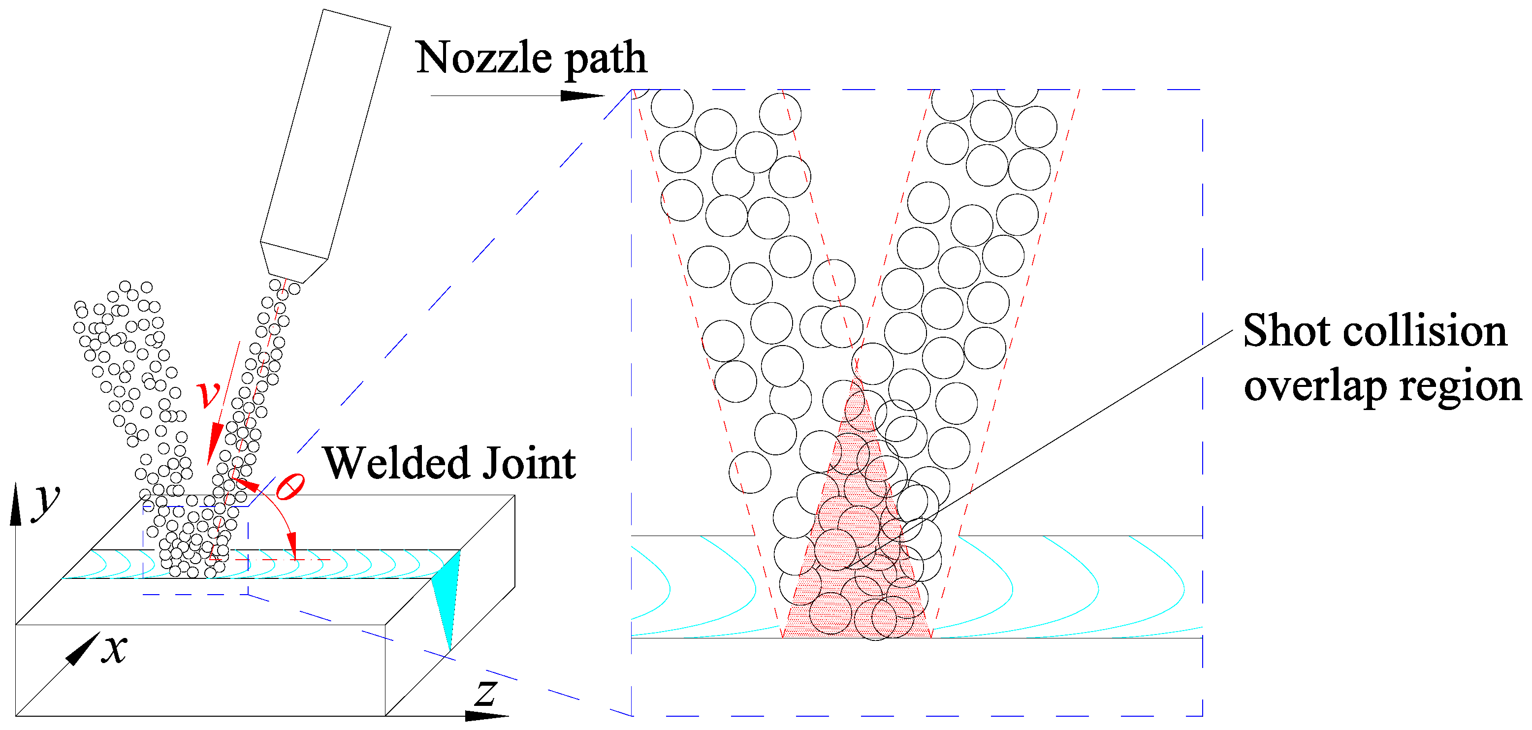
The pneumatic shot peening process for welded joints is schematically depicted in Figure 1. Numerous spherical shots are accelerated and ejected from the nozzle, forming a diverging shot stream that impacts the welded joint at a defined incident angle θ with an initial shot velocity v. As the nozzle traverses horizontally along the weld seam, the shot stream follows the nozzle path, forming a continuous impact region. In the impact region, high-velocity shots induce plastic deformation and generate residual compressive stresses.
As shown in Figure 1, the trajectories of incident and rebounding shots overlap within the red-shaded shot collision overlap region. Massive collisions between incident and rebounding shots readily occur in this region, which decrease the normal impact velocity (i.e., the normal component of the impact velocity). Such velocity attenuation is mainly affected by the following shot peening parameters.
  • Effect of shot diameter d: For a given mass flow rate rm, a small shot diameter d corresponds to a large number of shots, leading to a dense shot distribution along the flow path, high collision probability, and a significant reduction in the normal impact velocity. In contrast, a large shot diameter d reduces the number of shots, leading to a sparse distribution along the flow path, low collision probability, and only a slight reduction in the normal impact velocity.
  • Effect of incident angle θ: At a small incident angle θ, the normal impact velocity is inherently low, and the small overlap area between incident and rebounding trajectories results in low collision probability. Conversely, at a large incident angle θ, the normal impact velocity is large, but the large overlap area between the two trajectories results in high collision probability, which in turn causes a notable reduction in the normal impact velocity.
  • Effect of initial shot velocity v: For a given mass flow rate rm, shots distribute densely along the flow path at a low initial shot velocity v, leading to high collision probability and a significant reduction in the already low normal impact velocity. In contrast, shots distribute sparsely along the flow path at a high initial shot velocity v, leading to low collision probability and only a slight reduction in the already high normal impact velocity.
  • Effect of mass flow rate rm: At a small mass flow rate rm, shots distribute sparsely along the flow path, which reduces shot density in the overlap region. This results in low collision probability and only a slight reduction in the normal impact velocity. At a large mass flow rate rm shots distribute densely along the flow path, which increases shot density in the overlap region. This leads to high collision probability and a significant reduction in the normal impact velocity. However, a large mass flow rate rm is conducive to increasing the peening coverage rate.

2.2. Forming and Coupling Mechanism of Residual Stress Field

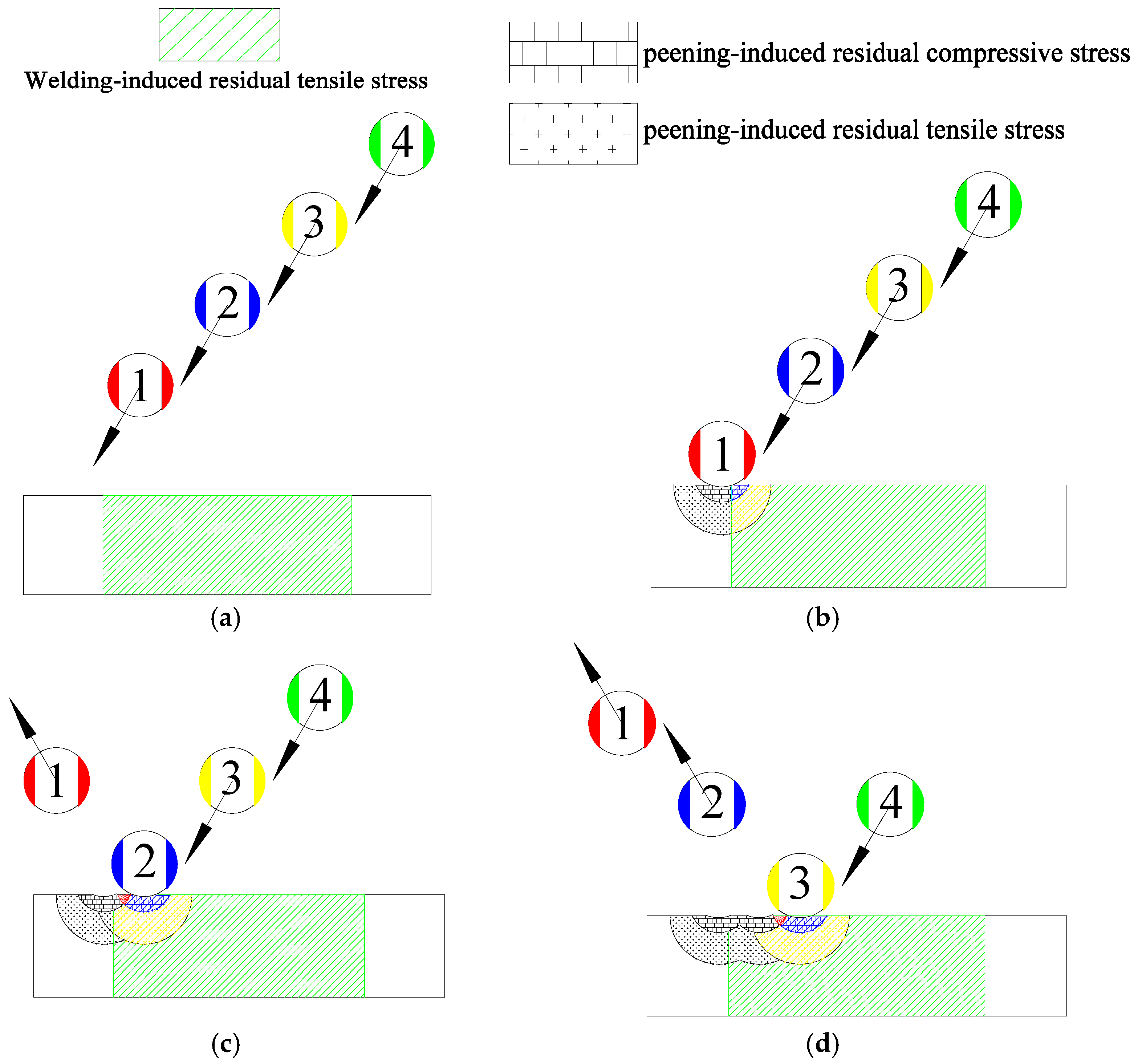
Figure 2 illustrates the mechanism by which pneumatic shot peening improves the residual stress field of a Q235B welded joint. Before shot peening, welding introduces residual tensile stress in the weld joint region, as indicated by the green-shaded region in Figure 2a.
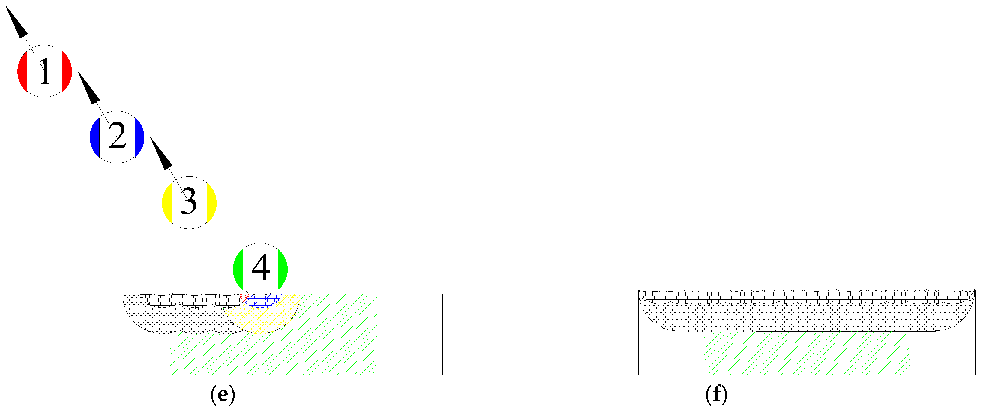
During the peening process, high-velocity spherical shots successively impact the target. At a specific moment, four random shots are shown to impact the target one after another: The first shot (red, ①) impacts the surface and then rebounds, generating a hemispherical residual stress field characterized by residual compressive stress in the impact core and residual tensile stress at its periphery. This peening-induced residual stress field couples with the pre-existing welding-induced residual stress field. In regions where the peening-induced residual compressive stress overlaps with the welding-induced residual tensile stress, the residual stress transforms from tensile to compressive (blue-shaded region in Figure 2b). In contrast, in regions where the peening-induced residual tensile stress overlaps with the welding-induced residual tensile stress, the residual tensile stress is amplified (yellow-shaded region in Figure 2b). Next, the second shot (blue, ②) impacts the surface, forming a new hemispherical residual stress field (Figure 2c). The same coupling mechanism repeats. Moreover, in the red-shaded region (Figure 2c), the residual compressive stresses induced by shot ① and shot ② superimpose, resulting in an increase in the magnitude of residual compressive stress. The third (yellow, ③) and fourth (green, ④) shots continue to impact the surface sequentially. Each newly induced residual stress field couples with the residual stress field induced by previous shots, gradually building up a continuous, overlapping residual stress field, as shown in Figure 2d,e. When a large number of shots sufficiently impact the target to achieve a full peening coverage rate, the original welding-induced residual tensile stress in the near-surface layer is fully transformed into residual compressive stress, as depicted in Figure 2f. Consequently, a continuous residual compressive stress layer is formed in the near-surface layer of the welded joint, while the residual tensile stress is confined to the subsurface region. In addition, the successive high-velocity impacts inevitably produce an uneven surface topography.

3. Model Establishment

The simulation of the pneumatic shot peening process for welded joints is divided into two sequential stages. (1) Welding simulation: The welding process is first simulated using a 3D double-ellipsoidal heat source model to obtain the temperature field and the resulting welding-induced residual stress field. (2) Shot peening simulation: The shot peening process is then simulated using a DEM-FEM coupled model, with the welding-induced residual stress field obtained from the previous stage introduced as the initial stress condition.

3.1. Material Properties

The material in this study is Q235B carbon steel, whose chemical composition conforms to the Chinese standard GB/T 700-2006 [26], as listed in Table 1. The thermal and mechanical properties of Q235B are considered in both the welding and shot peening simulations, as detailed below.

3.1.1. Thermal Properties

During welding, the intense heat input causes a rapid temperature rise in the welded joint, leading to significant changes in the material’s thermal properties. To accurately capture these effects, the temperature-dependent thermal and mechanical parameters, including Poisson’s ratio, elastic modulus, yield strength, density, specific heat capacity, thermal conductivity, and linear expansion coefficient, are adopted in the welding simulation. These parameters are extracted from the published literature [23].

3.1.2. Mechanical Properties

During shot peening, the target undergoes high-strain-rate plastic deformation due to the impact of high-velocity shots. To describe the material behavior under such extreme conditions, the Johnson-Cook constitutive model [27] is employed. This model accounts for the combined effects of strain hardening, strain rate sensitivity, and thermal softening, and it is widely used in impact and dynamic loading simulations.
The equivalent yield stress σ is expressed as:
σ = A + B ε n 1 + C ln ε ˙ ε ˙ 0 1 T     T 0 T m     T 0 m
where T0 is the reference temperature (room temperature 20 °C in this study); A is the yield strength under quasi-static loading at T0; B is the strain hardening modulus; ε is the equivalent plastic strain; n is the strain hardening exponent; C is the strain rate sensitivity coefficient; ε ˙ is the equivalent plastic strain rate; ε ˙ 0 is the reference strain rate; T is the working temperature; T m is the melting temperature; and m is the thermal softening exponent. The constants of the Johnson-Cook model for Q235B steel are listed in Table 2.

3.2. Welding Model

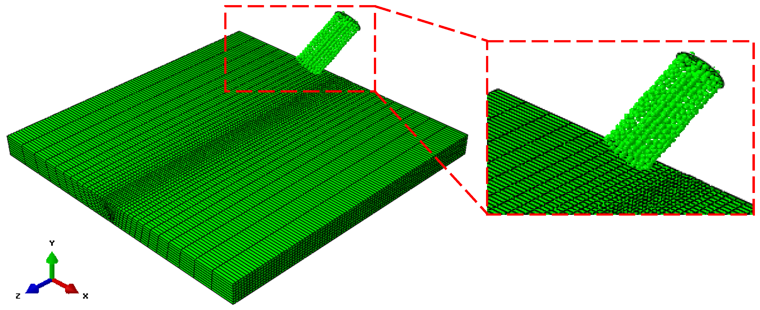
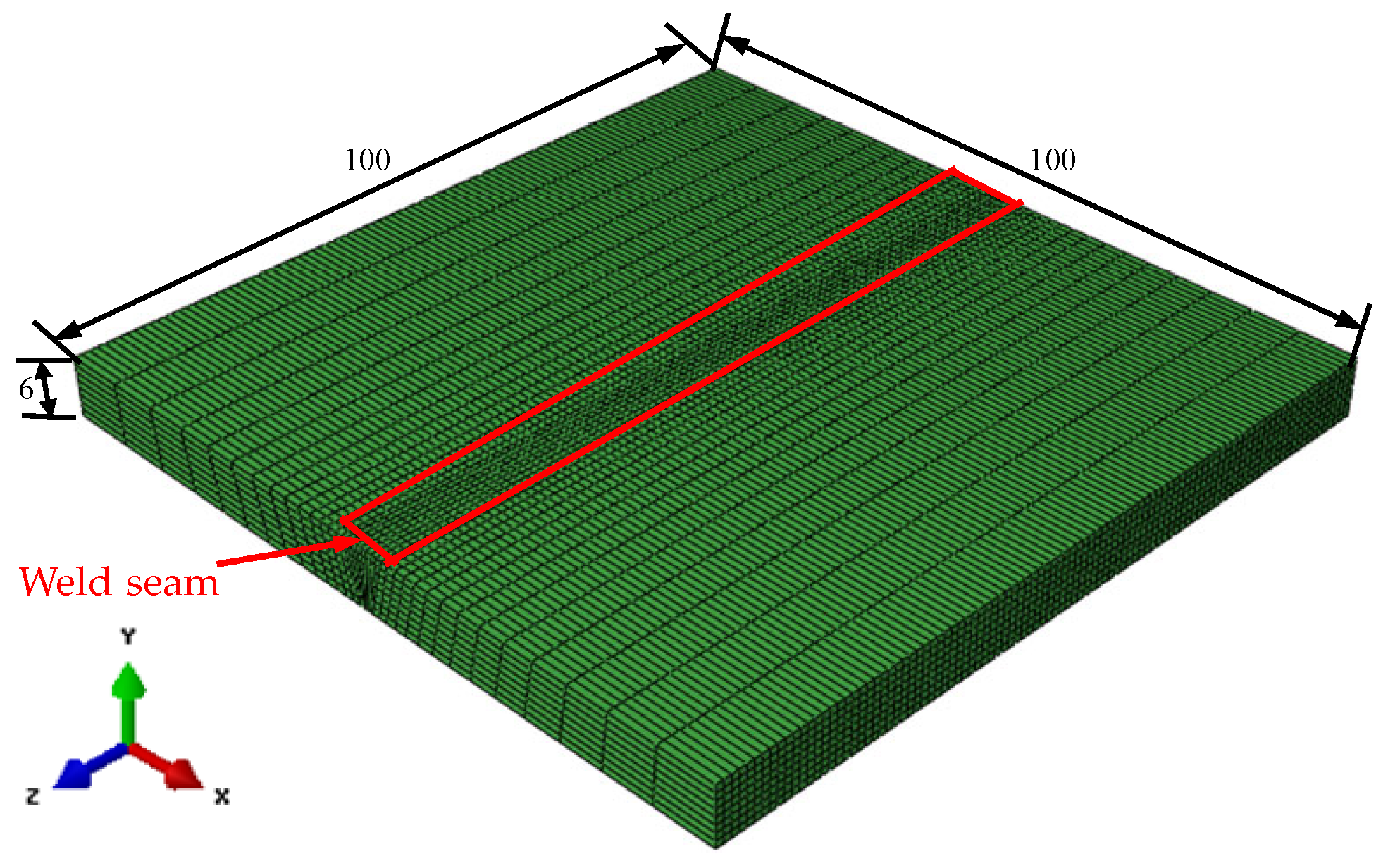
The welding model is established based on two Q235B carbon steel plates with dimensions of 100 mm × 47 mm × 6 mm, forming a butt joint with a weld width of 6 mm. Manual metal arc welding is adopted, with the following process parameters: welding voltage of 25 V, welding current of 150 A, and welding speed of 2 mm/s. Two different element types are employed: the 8-node linear heat transfer brick element DC3D8 for temperature field analysis, and the 8-node linear brick element with reduced integration C3D8R for residual stress field analysis. To balance computational efficiency and numerical accuracy, a graded mesh strategy is implemented, as shown in Figure 3: the region near the weld seam is divided with a fine mesh, while the region far from the weld seam is divided with a relatively coarse mesh. The total number of elements in the model is 144,000.
Comprehensive thermal boundary conditions are defined for the welded plate. Free air convection heat transfer is applied to the upper and side surfaces of the workpiece, with convection coefficient h = 10 W/(m2·°C) and ambient temperature 20 °C. A constant contact heat conduction boundary is set on the bottom surface of the plate to simulate heat dissipation to the steel fixture base. All surfaces are assigned radiation heat exchange with the surrounding environment, with emissivity of Q235B carbon steel set to 0.85. The Stefan-Boltzmann constant is 5.67 × 10⁻⁸ W/(m2·K4).
This welding simulation adopts the Goldak 3D double-ellipsoidal heat source model combined with the element birth-and-death technique, which is employed to reproduce the progressive formation of the weld pool and the associated thermo-mechanical response. Compared with a point heat source, plane heat source and single ellipsoidal heat source, the Goldak model distinguishes the asymmetric temperature gradient distribution at the front and rear of the molten pool, which can accurately reproduce the real thermal cycle characteristic of manual metal arc welding. The Goldak 3D double-ellipsoidal heat source is applied through the DFLUX user subroutine.
The Goldak 3D double-ellipsoidal heat source assigns different energy partition coefficients to the front and rear ellipsoids of the molten pool. The front ellipsoid possesses higher energy density, which produces compact isotherms and a steep temperature gradient in the region ahead of the heat source. By contrast, the rear ellipsoid has a lower energy proportion, forming sparse isotherms and a much milder temperature gradient behind the weld pool. This inherent asymmetric energy distribution distinguishes the double-ellipsoidal model from single-ellipsoidal or planar Gaussian heat sources, and it inherently reproduces the uneven thermal gradient feature observed in actual arc welding processes. The volumetric heat flux for the front and rear ellipsoidal regions is expressed as follows:
q 1 x , y , z = 6 3 f 1 Q π π a b c 1 exp     3 x 2 a 2     3 y 2 b 2     3 z 2 c 1 2
q 2 x , y , z = 6 3 f 2 Q π π a b c 2 exp 3 x 2 a 2 3 y 2 b 2 3 z 2 c 2 2
where q1 and q2 denote the volumetric heat flux of the front and rear ellipsoids; f1 and f2 are the energy partition coefficients for the front and rear ellipsoids, with f1 = 0.6, f2 = 1.4. The symbols a, b, c1, and c2 are the heat source shape parameters, which are set to a = 4.5 mm, b = 6 mm, c1 = 2.5 mm and c2 = 7.5 mm in this study.
The total welding heat input power Q is defined as:
Q = ηUI
In which η is the welding thermal efficiency, which is set to η = 0.85; U is the welding voltage; and I is the welding current.

3.3. Shot Peening Model

The shot peening simulation is carried out via the ABAQUS/Explicit (2022) solver. The welding-induced residual stress field calculated in the welding simulation is imported and defined as the initial stress condition. A DEM-FEM coupled model is established to characterize the pneumatic shot peening behavior. Different model components are assigned with corresponding element types: the shots are modeled with discrete elements PD3D, the welded joint is meshed using C3D8R solid elements, and the nozzle is simplified with 4-node surface elements SFM3D4R.
In terms of boundary conditions, the bottom surface of the welded joint is fully fixed to restrict motion. Different contact behaviors are defined for different interaction pairs. The general contact algorithm is adopted for shot–target contact. The Hertz contact algorithm is adopted for shot–shot contact, with non-penetration constraints imposed to eliminate numerical singularities. The interaction coefficients of shot–shot and shot–target are set according to Table 3.
The normal contact force between two colliding shots follows the Hertz elastic contact theory:
F H = 4 3 E × R 1 2 δ 3 2
where the equivalent radius R and equivalent elastic modulus E are defined as:
1 R = 1 R 1 + 1 R 2
1 E = 1 ν 1 2 E 1 + 1 ν 2 2 E 2
where R1 and R2 are the radii of the two colliding shots; E1 and E2 are their elastic moduli; ν1 and ν2 are their Poisson’s ratios; and δ is the contact penetration between the two colliding shots.
The inner diameter of the nozzle is set to 6 mm, and the stand-off distance is set to 20 mm. Four key control variables, including shot diameter d, incident angle θ, initial shot velocity v and mass flow rate rm are selected for parametric analysis. The range of each parameter is determined based on three foundations: (1) industrial pneumatic shot peening equipment common working range for carbon steel welded structures; (2) relevant published numerical and experimental studies on shot peening of low-carbon steel weldments [22,23]; (3) pre-simulation trial runs to avoid excessive shot collision or insufficient plastic deformation. For shot diameter d: 0.4–1.0 mm covers conventional steel shot specifications for surface strengthening; for incident angle θ: 30–90° covers oblique to normal impact states to reveal trajectory overlap collision rules; for initial shot velocity v: 20–60 m/s represents low to medium high energy impact without exceeding Q235B fracture strength; for mass flow rate rm: 3–12 kg/min distinguishes sparse, moderate and dense distribution along the flow path. The specific parameter combinations are summarized in Table 4 to quantitatively separate the individual influence of each factor on residual stress distribution.
In the shot peening simulation, numerous randomly distributed shots are ejected from the nozzle and accelerated toward the target, forming continuous impact on the welded joint, as shown in Figure 4.

3.4. Model Verification

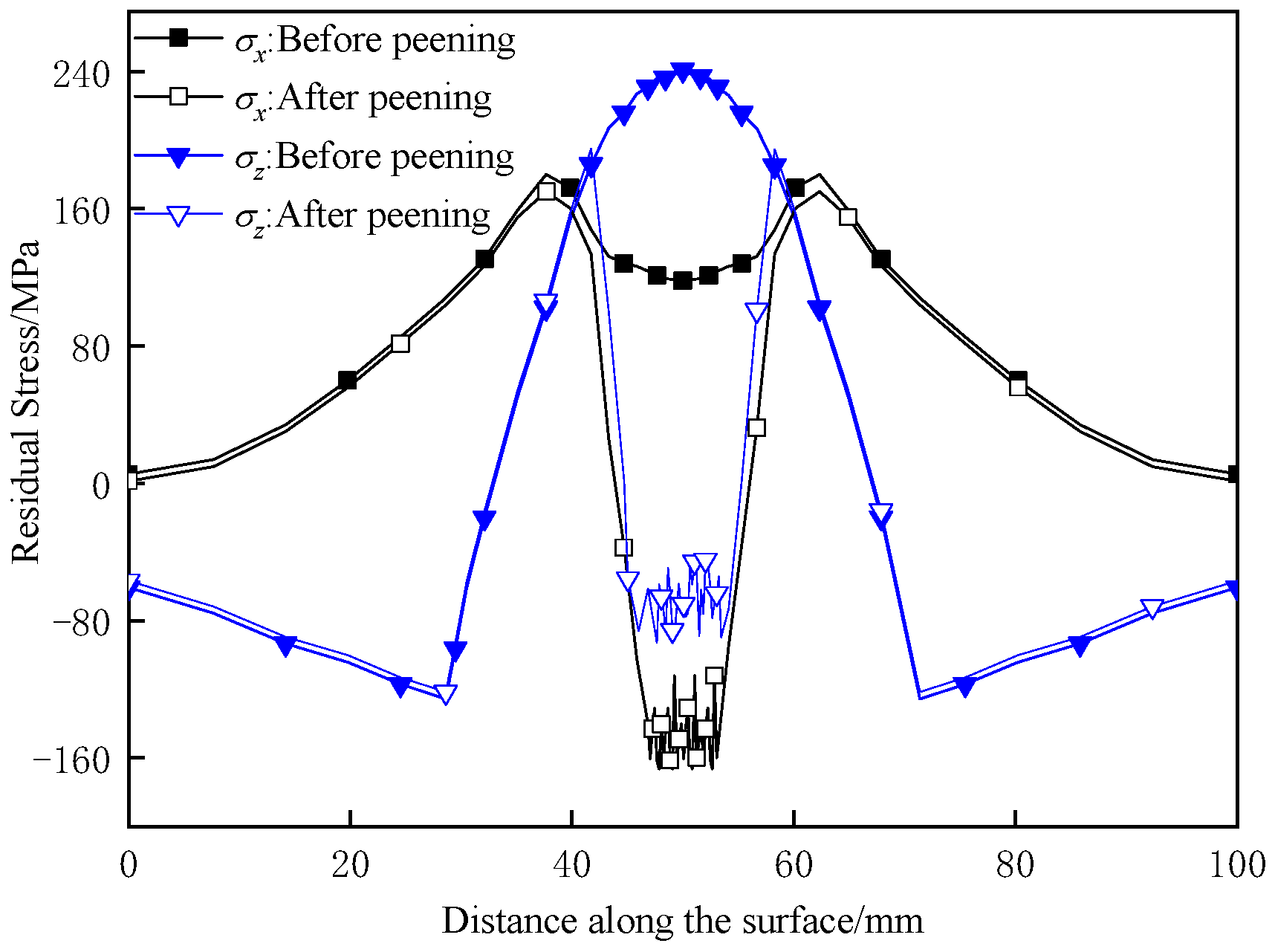
To verify the accuracy and reliability of the established coupled welding-shot peening model, numerical simulation is carried out under the parameters of d = 0.4 mm, θ = 90°, ν = 40 m/s, rm = 6 kg/min, as shown in Figure 5. Limited by experimental conditions, this study verifies the overall residual stress distribution trend by comparing with published surface strengthening treatment results. The surface residual stress distributions before and after peening are extracted and compared with the water jet peening results reported in the reference [29]. It should be noted that shot peening and water jet peening belong to different surface strengthening techniques, with differences in impact media and loading forms. However, the comparison results show that the evolution trends of surface residual stress obtained from the present simulation and the reference are in good agreement. Before peening, the longitudinal residual stress σx presents a crater-shaped distribution, while the transverse residual stress σz shows a mountain-shaped distribution. After peening, both σx and σz in the weld zone are transformed from residual tensile stress to residual compressive stress, which confirms that surface strengthening can effectively improve the residual stress field of welded joints.
In the future, we will arrange multi-point thermal cycle measurement experiments on Q235B welded joints, collect repeated temperature data, calculate standard deviation and carry out statistical significance analysis to further improve the reproducibility and reliability of the model.
Although there exist certain quantitative deviations caused by different strengthening methods and material parameters, the overall consistent distribution characteristics sufficiently verify the rationality of the established welding model and shot peening model. Therefore, the proposed DEM-FEM coupled model is reliable and feasible to investigate the residual stress improvement effect of pneumatic shot peening on Q235B welded joints.

4. Results and Discussion

4.1. Welding Temperature and Welding-Induced Residual Stress Field

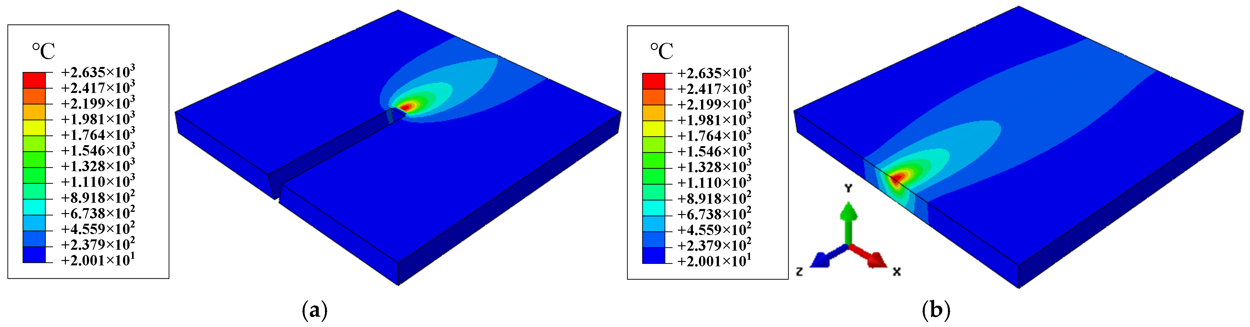
Figure 6 shows the evolution of the transient temperature field during the welding process. As the double-ellipsoidal heat source moves along the weld seam, the material near the weld seam is heated rapidly, and the temperature inside the molten pool exceeds the melting point of Q235B steel. At t = 25 s, half of the weld elements are activated by the element birth-and-death method, and the maximum temperature reaches 2635 °C. At t = 50 s, all weld elements are fully activated, indicating the completion of welding. Afterwards, the welded joint is cooled down to room temperature of 20 °C within about 5000 s, so as to form a stable residual stress field.
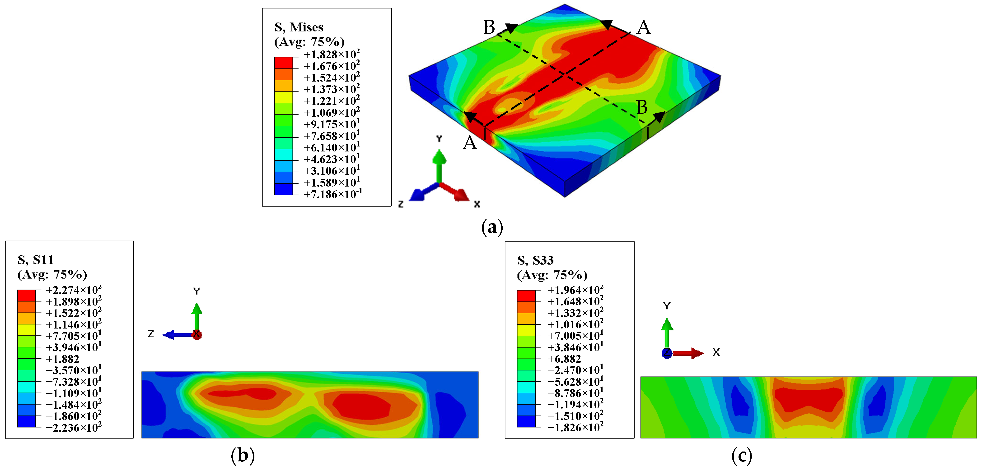
The welding-induced residual stress field after cooling is presented in Figure 7. Due to non-uniform thermal cycling, obvious residual stress concentrates in the weld zone and its adjacent area. The longitudinal residual stress σx along the weld seam is mainly tensile. The transverse residual stress σz perpendicular to the weld seam presents a mountain-shaped distribution: residual tensile stress prevails inside the weld seam, whereas residual compressive stress occurs at both ends of the weld seam. The maximum values of von Mises stress, longitudinal residual stress and transverse residual stress are 182.8 MPa, 227.4 MPa and 196.4 MPa, respectively.

4.2. Effects of Shot Peening Parameters on the Residual Stress Field

As a large area residual tensile stress occurs after welding, shot peening is adopted for improving the residual stress field. Next, the effects of shot diameter d, initial shot velocity v, incident angle θ and mass flow rate rm on the longitudinal residual stress σx and the transverse residual stress σz are investigated.

4.2.1. Effect of Shot Diameter d

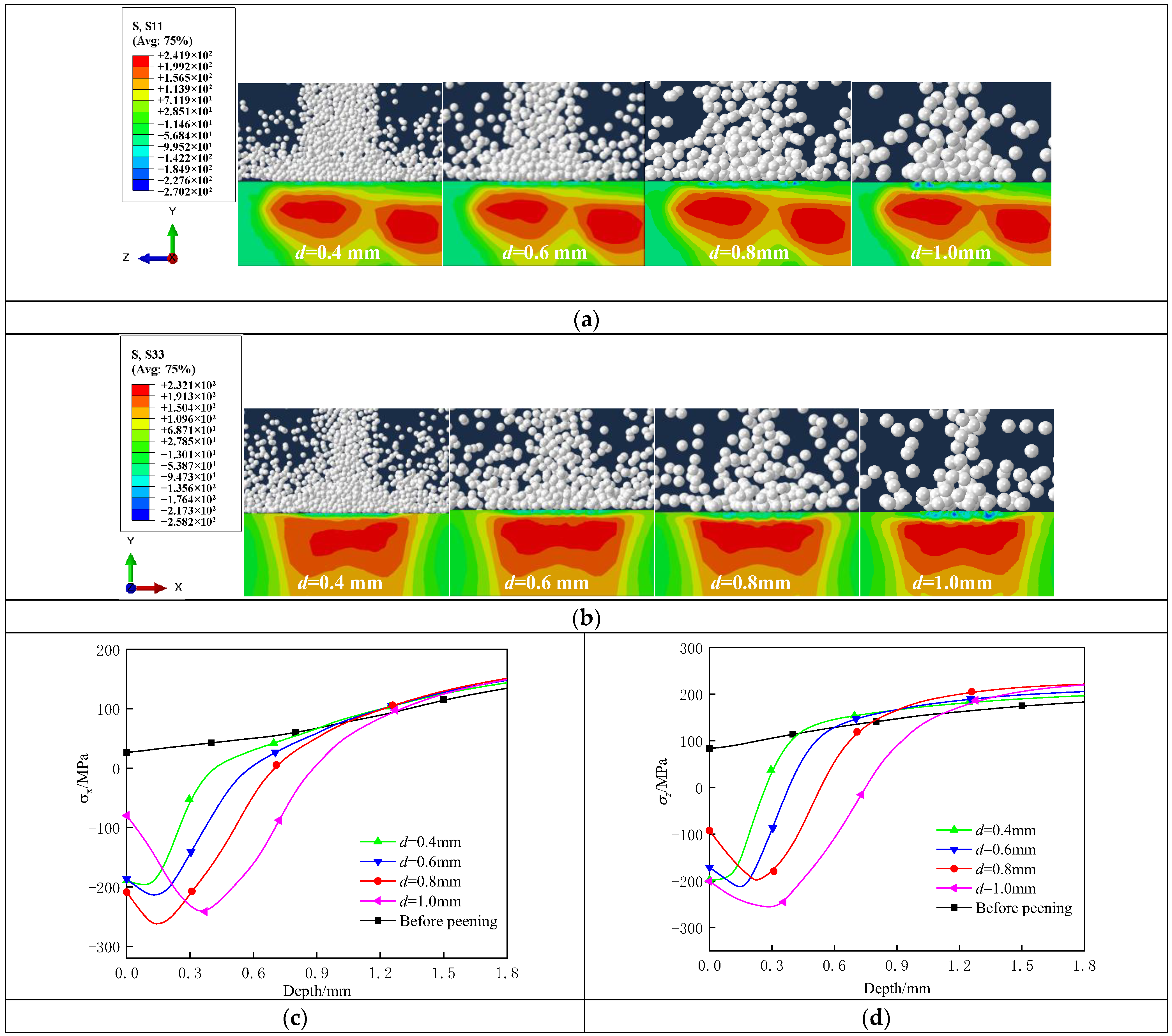
Figure 8 displays the distributions of σx and σz after shot peening for shot diameters of 0.4 mm, 0.6 mm, 0.8 mm and 1.0 mm, with fixed parameters θ = 90°, v = 60 m/s, rm = 6 kg/min. After shot peening, the original welding-induced residual tensile stress in the near-surface layer is transformed into residual compressive stress and a continuous residual compressive stress layer is formed in the near-surface layer, owing to the overlap between the peening-induced residual compressive stress and the welding-induced residual tensile stress. It is found that the maximum residual compressive stress appears in the near-surface layer rather than on the surface, which is a typical feature of shot peening. Meanwhile, the residual tensile stress is confined to the subsurface region, and its value is even slightly larger than the original welding-induced residual tensile stress, owing to the overlap between the peening-induced residual tensile stress and the welding-induced residual tensile stress.
For a given mass flow rate, an increase in shot diameter d reduces the number of shots, which lowers collision probability and weakens the attenuation of normal impact velocity and impact energy. Furthermore, an increase in shot diameter d results in a larger impact area, which can induce deeper plastic deformation. Accordingly, with the increase in d, the depth of the maximum residual compressive stress and the depth of the residual compressive stress layer both increase significantly. Quantitatively, when d increases from 0.4 mm to 1.0 mm, the depth of the maximum residual compressive stress of σx and σz increases to 0.37 mm and 0.31 mm, respectively, and the depth of the residual compressive stress layer of σx and σz increases to 0.92 mm and 0.74 mm, respectively.
Overall, for a given mass flow rate, a large shot diameter achieves a significant residual stress improvement due to high impact energy and large impact area. Thus, selecting a large shot diameter is conducive to achieving the optimum residual stress improvement for welded joints.

4.2.2. Effect of Incident Angle θ

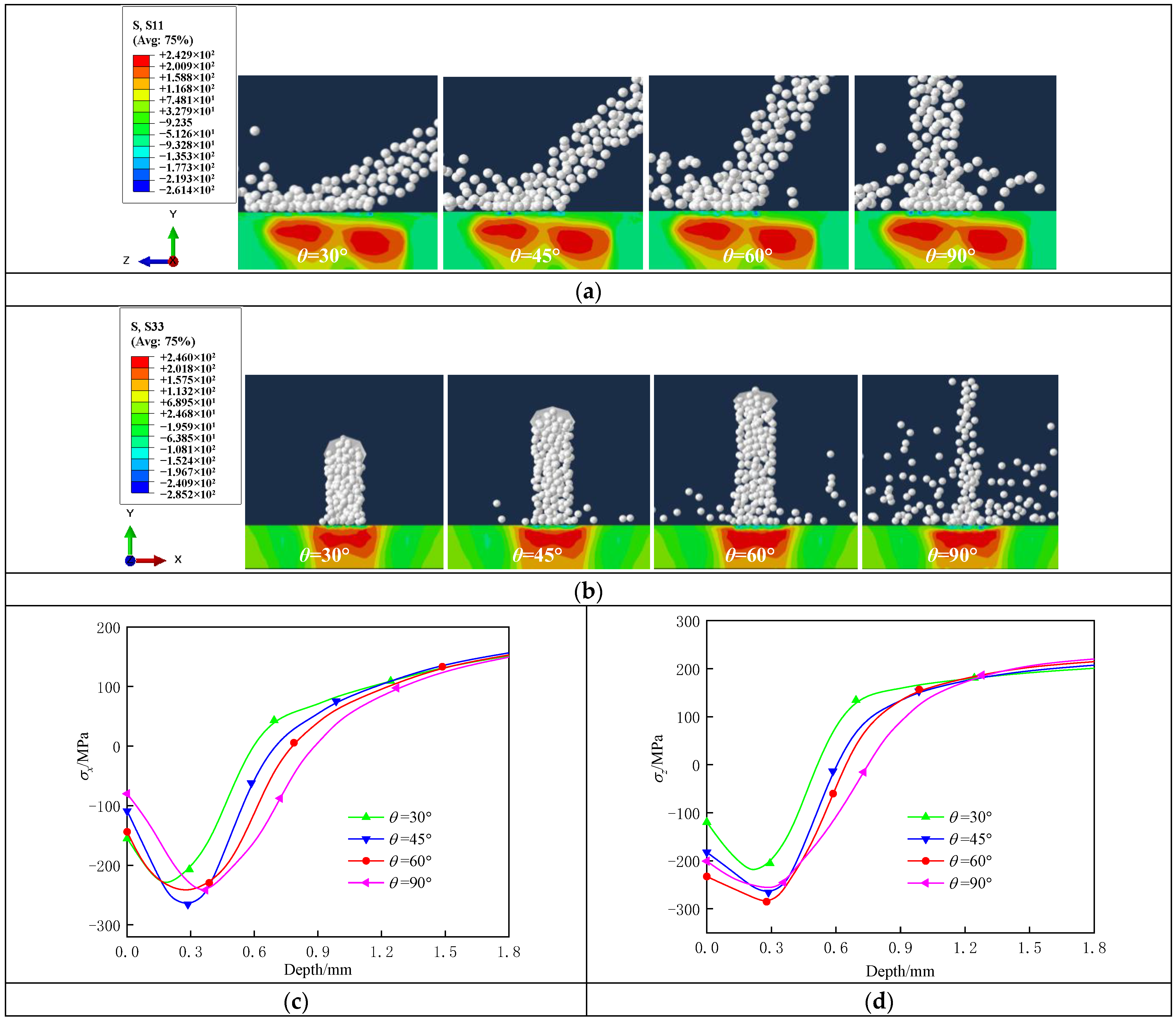
Figure 9 displays the distributions of σx and σz after shot peening for incident angles of θ = 30°, 45°, 60° and 90°, with fixed parameters of d = 1 mm, v = 60 m/s, and rm = 6 kg/min. As θ increases, the normal impact velocity and the impact energy increase, which promotes deeper plastic deformation and further enlarges the depth of residual compressive stress layers for both σx and σz. However, the maximum residual compressive stress does not increase monotonically: As θ increases from 30° to 60°, the increasing normal impact velocity plays a leading role in intensifying plastic deformation, thus increasing the maximum residual compressive stress. As θ exceeds 60°, the overlap area between incident and rebounding trajectories expands, significantly increasing collision probability and attenuating the normal impact velocity and the impact energy. Such energy attenuation offsets the advantages brought by larger incident angles and consequently causes the maximum residual compressive stress to decrease.
Therefore, to balance the maximum residual compressive stress and the depth of the residual compressive stress layer, selecting a suitable incident angle is conducive to achieving the optimum residual stress improvement for welded joints.

4.2.3. Effect of Initial Shot Velocity v

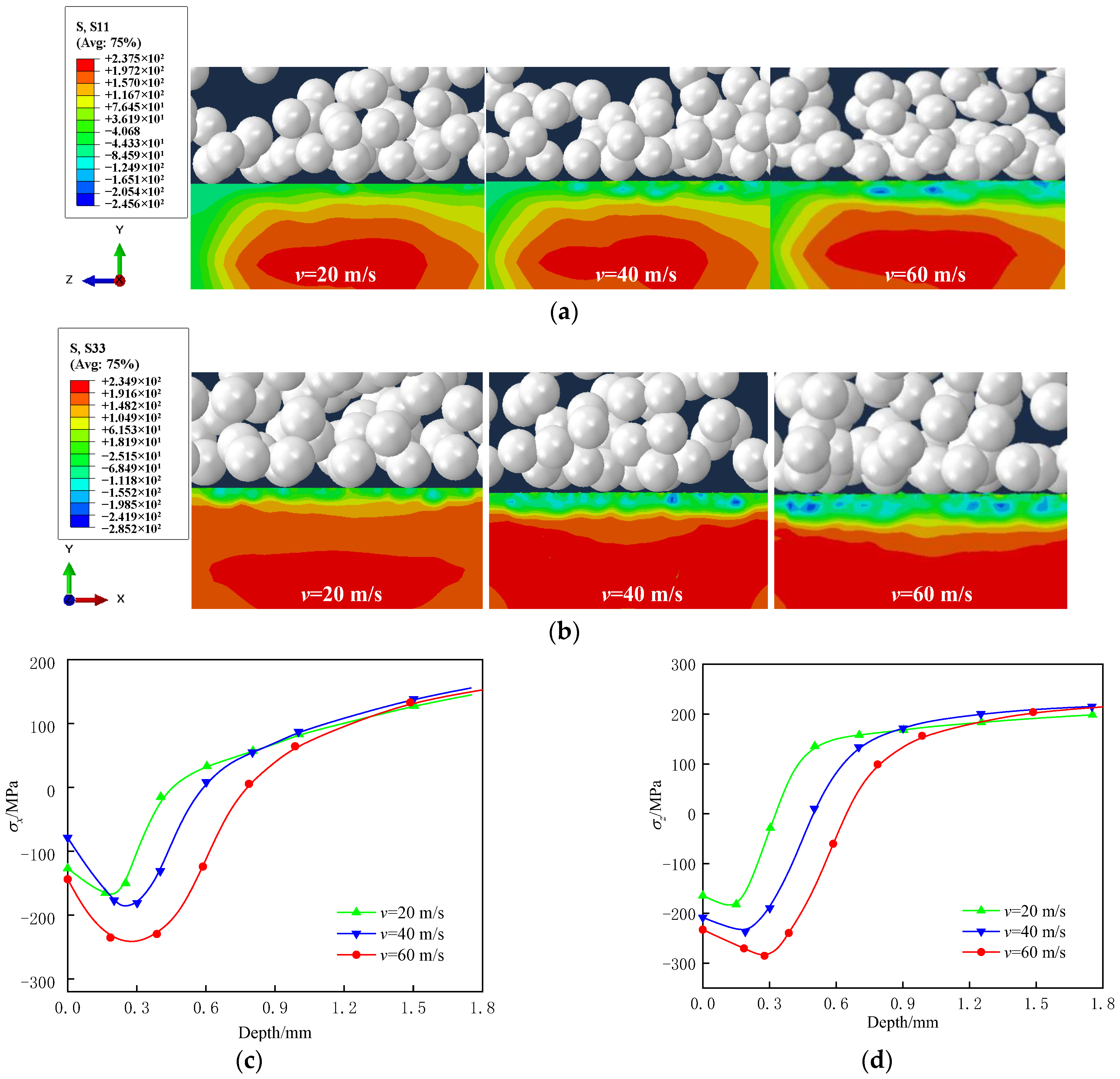
Figure 10 displays the distributions of σx and σz after shot peening for initial shot velocities of v = 20, 40 and 60 m/s, with fixed parameters d = 1 mm, θ = 60°, rm = 6 kg/min. As v increases, the maximum residual compressive stress, the depth of the maximum residual compressive stress and the depth of the residual compressive stress layer all increase significantly for both σx and σz. This trend is driven by two coupled effects. On one hand, higher shot velocity delivers greater impact energy and induces deeper plastic deformation. On the other hand, it lowers collision probability, alleviates velocity attenuation and maintains sufficient effective impact energy. Quantitatively, when v increases from 20 m/s to 60 m/s, the maximum residual compressive stresses increase to −245 MPa for σx and −285 MPa for σz; the depths of the maximum residual compressive stress increase to 0.29 mm for σx and 0.28 mm for σz; and the depths of the residual compressive stress layer increase to 0.80 mm for σx and 0.65 mm for σz.
Overall, a large initial shot velocity achieves a significant residual stress improvement due to high impact energy. Thus, selecting a large initial shot velocity (not exceeding the fracture strength of the welded joint) is conducive to achieving the optimum residual stress improvement for welded joints.

4.2.4. Effect of Mass Flow Rate rm

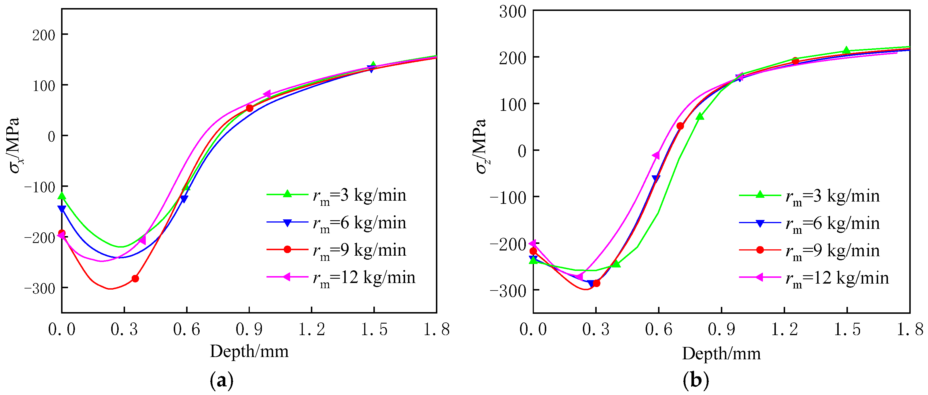
Figure 11 displays the distributions of σx and σz after shot peening for mass flow rates of rm = 3, 6, 9 and 12 kg/min, with fixed parameters of d = 1 mm, θ = 60°, and v = 60 m/s. For both σx and σz, the maximum residual compressive stress does not increase monotonically with the increase in rm. As rm increases from 3 kg/min to 9 kg/min, the maximum residual compressive stress increases gradually. This is because the increased number of shots can effectively increase both the coverage rate and the degree of plastic deformation. As rm exceeds 9 kg/min, the maximum residual compressive stress begins to decrease. This is because the excessive number of shots increases collision probability, attenuates the normal impact velocity and the impact energy, and eventually weakens the improvement effect of shot peening.
Overall, selecting a suitable mass flow rate is conducive to achieving optimum residual stress improvement for welded joints.

4.3. Evaluation of Improvement Effect

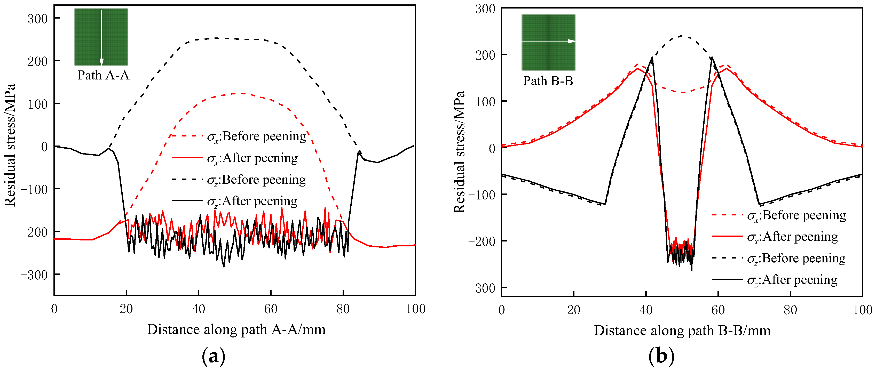
Based on the above parametric analysis, a set of reasonable shot peening parameters including d = 1 mm, θ = 60°, v = 60 m/s and rm = 9 kg/min are selected to simulate and compare the residual stress field before and after shot peening. Figure 12 presents the distributions of σx and σz along paths A-A and B-B before and after shot peening. After shot peening, both σx and σz on the surface are transformed from residual tensile stress into residual compressive stress, with their maximum values reaching −241 MPa and −275 MPa, respectively.
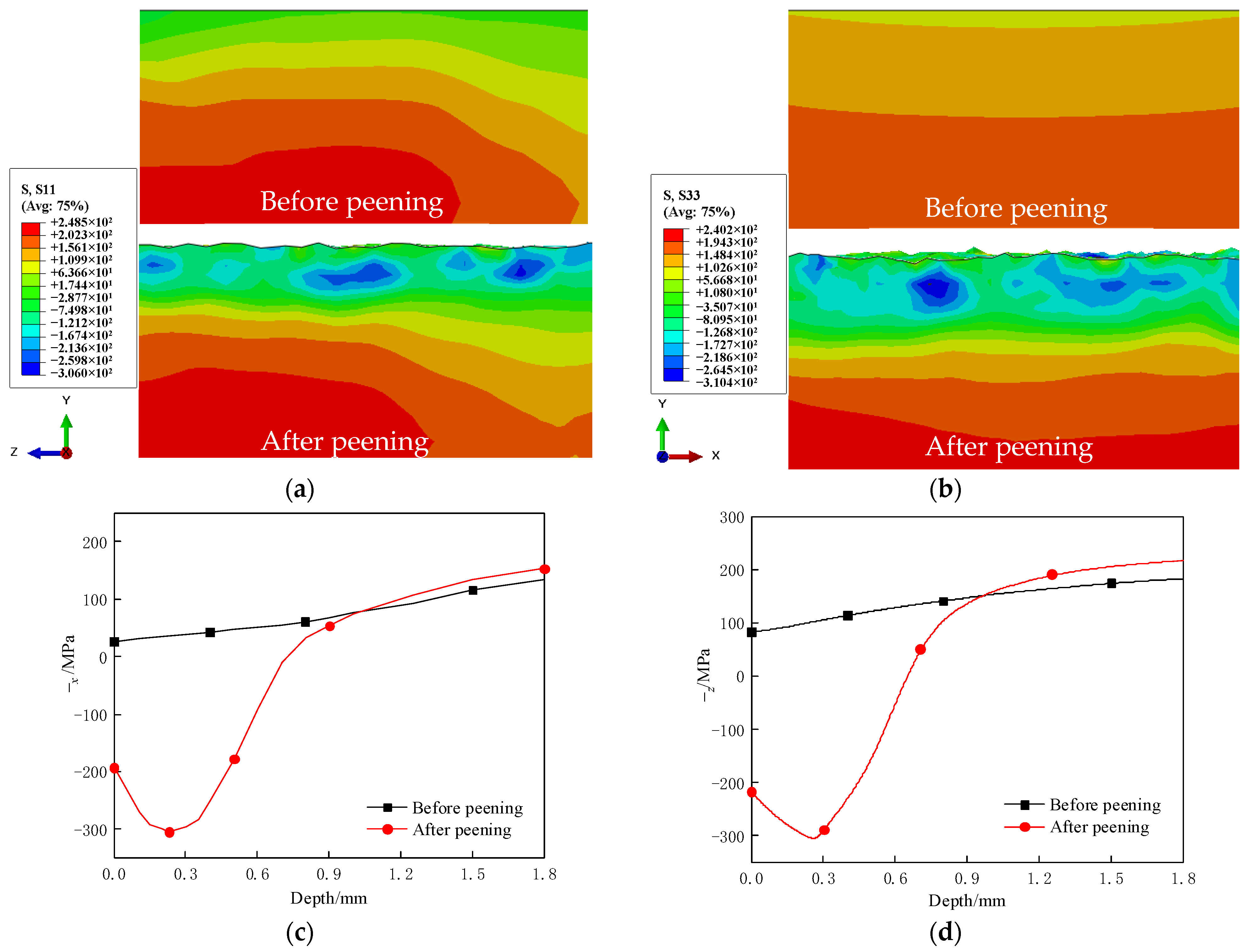
Figure 13 presents the residual stress fields in the depth direction at the weld seam before and after shot peening. The cloud atlases (a, b) and corresponding curves (c, d) for both σx and σz clearly demonstrate the significant improvement effect of shot peening. Before shot peening, the near-surface regions are dominated by residual tensile stresses. After shot peening, both σx and σz in the near-surface layer are transformed into residual compressive stresses. Quantitatively, the surface residual compressive stresses reach −241 MPa for σx and −275 MPa for σz. The maximum residual compressive stresses reach −306 MPa for σx and −310 MPa for σz. The depths of the maximum residual compressive stress reach 0.24 mm for σx and 0.27 mm for σz. The depths of the residual compressive stress layer reach 0.78 mm for σx and 0.66 mm for σz. These results confirm that the selected shot peening parameters have effectively introduced a deep residual compressive stress layer.
In conclusion, shot peening can effectively eliminate residual tensile stresses and introduce residual compressive stresses, thereby significantly improving the residual stress state of welded joints.

4.4. Discussion

4.4.1. Comparison with Experimental Observations from Published Works

Consistent with the experimental conclusions of Nie et al. [19] and Wei et al. [23], the depth of maximum residual compressive stress and the depth of the compressive stress layer both increase with the increase in shot diameter and shot velocity. Lai et al. [18] also verified that increasing peening time can expand the plastic deformation depth beneath the weld surface, which matches our simulated trend that higher v delivers a deeper residual compressive stress layer.
For incident angle, existing single-shot FE models mostly concluded that normal vertical impact θ = 90° yields the maximum compressive stress. However, this study draws a different optimal angle of 60°, which arises from the novelty of our random multi-shot DEM module: large incident angles produce overlapping shot trajectories and severe shot–shot collision, attenuating effective impact energy. This mechanism is rarely quantified in previous simplified peening simulations with neatly arranged shots [25].
Regarding mass flow rate, the non-monotonic variation in maximum compressive stress (rising first then declining) agrees with the results of Chen et al. [21]. Excessive mass flow rate causes dense shot distribution along the flow path and continuous collisions between shots, which fully explains the “over-peening” phenomenon observed in practical shot peening operations.

4.4.2. Advantages of the Proposed Sequentially Coupled Welding-Shot Peening Model

Most previous numerical studies only established separate peening models without importing pre-existing welding-induced residual tensile stress fields as initial conditions [24,25]. This work realizes a sequential thermo-mechanical welding simulation and a DEM-FEM dynamic peening coupling simulation, directly reproducing the superposition and offset mechanism between welding tensile stress and peening compressive stress.
Different from conventional pure FEM shot peening models with artificially arranged shots, the ABAQUS DEM module adopted in this study generates randomly ejected shots and fully calculates collision energy attenuation, which can more accurately reflect practical shot peening operations.

4.4.3. Engineering Implication of Optimized Parameters

The optimal parameter combination adopted in this study, d = 1 mm, θ = 60°, v = 60 m/s and rm = 9 kg/min, can provide quantitative guidance for post-weld surface strengthening of Q235B welded joints. Under this set of process parameters, a continuous near-surface residual compressive stress layer with a depth of 0.78 mm is generated, which effectively restrains surface crack initiation induced by welding-induced residual tensile stress, and the corresponding surface residual compressive stresses reach −241 MPa and −275 MPa in two directions.
Wang et al. [30] conducted experimental shot peening tests on Q235 welded joints and measured residual compressive stresses of approximately −160 MPa at the weld seam and −200 MPa in the base metal after peening. Our simulated residual compressive stress levels fall within the same level as their measured values, and the moderate discrepancy arises from the larger shot diameter and higher impact velocity adopted in the present model. Their experimental data further reveal that shot peening improves the fatigue strength of welded specimens by 51% at 2 × 10⁶ loading cycles. Collectively, the residual compressive stress levels obtained in this study are verified to be reasonable and favorable for weld surface strengthening, as such stress levels can fully offset welding-induced surface residual tensile stress, inhibit fatigue crack nucleation, and markedly enhance the fatigue performance of welded structural components.

5. Conclusions

(1) Residual tensile stress exists in the weld zone of as-welded Q235B welded joints. Shot peening can effectively eliminate residual tensile stress and introduce residual compressive stress, thereby significantly improving the residual stress state of Q235B welded joints. Consequently, shot peening offers an effective technical method for improving the residual stress field of welded joints.
(2) For both the longitudinal residual stress σx and the transverse residual stress σz, the depth of the maximum residual compressive stress and the depth of the residual compressive stress layer increase with the increase in shot diameter d and incident angle θ. With the increase in initial shot velocity v, the maximum residual compressive stress, the depth of the maximum residual compressive stress and the depth of the compressive stress layer all increase correspondingly. Meanwhile, the maximum residual compressive stress first increases and then decreases with the increase in mass flow rate rm.
(3) A set of selected reasonable parameters including d = 1 mm, θ = 60°, v = 60 m/s, rm = 9 kg/min is proven highly effective in improving the residual stress field. After shot peening, the residual tensile stresses in the near-surface layer are transformed into residual compressive stresses, reaching −241 MPa for σx and −275 MPa for σz; the maximum residual compressive stresses reach −306 MPa for σx and −310 MPa for σz at depths of 0.24 mm and 0.27 mm; the depths of the residual compressive stress layer reach 0.78 mm for σx and 0.66 mm for σz, respectively.
(4) The established DEM-FEM coupled approach is verified to effectively capture the dynamic impact behavior and residual stress evolution of Q235B welded joints during shot peening. This numerical framework can be further extended to the residual stress regulation and fatigue performance optimization of other welded structural components.
For future research: (1) Carry out multi-point welding thermal cycle measurement experiments with repeated sampling and statistical analysis to calibrate the welding heat source model. (2) Complete shot peening residual stress measurement via X-ray diffraction to realize direct quantitative verification of simulation results. (3) Extend the DEM-FEM coupling model to other low-carbon steel and alloy welded joints.

Author Contributions

Conceptualization, K.C.; methodology, K.Z.; software, Y.C.; validation, K.C.; resources, K.C.; data curation, K.Z.; writing—original draft preparation, Y.C.; writing—review and editing, Y.C.; visualization, K.Z.; supervision, K.C.; project administration, Y.C.; funding acquisition, K.C. All authors have read and agreed to the published version of the manuscript.

Funding

This research was funded by Key Research and Development Project of Henan Province (grant number 221111220600).

Data Availability Statement

The original contributions presented in this study are included in the article. Further inquiries can be directed to the corresponding author.

Conflicts of Interest

The authors declare no conflicts of interest.

References

  1. Nukathoti, R.S.; Battina, N.M.; Vanthala, V.S.P.; Chirala, H.K.; Pulidandi, V.K.; Ramaswamy, A.; Narayana, R.L. Formability of AA6061—AA2017 dissimilar FSW joints: Effects of weld passes, material positioning, and post-weld shot peening. Eng. Res. Express 2026, 8, 15523. [Google Scholar] [CrossRef]
  2. Ahola, A.; Lipiäinen, K.; Riski, J.; Koskimäki, M.; Pyörret, J.; Björk, T. Fatigue strength of shot-peened as-welded joints and post-weld-treated and subsequently clean-blasted fillet weld joints. Weld. World 2023, 67, 1559–1574. [Google Scholar] [CrossRef]
  3. Mallieswaran, K.; Rajendran, C.; Padmanabhan, R.; Rajasekaran, S. Evaluation of nickel shot peening process on strength of friction stir welded AA2014-T6 aluminum alloy joints. Pract. Metallogr. 2023, 60, 442–460. [Google Scholar] [CrossRef]
  4. Li, G.; Xu, W.; Liang, Y.; Wang, J. Effect of Ultrasonic Shot Peening on Microstructure and Properties of Variable Polarity Plasma Arc Welding Joints of 7A52 Aluminum Alloy. J. Mater. Eng. Perform. 2025, 8, 6697–6707. [Google Scholar]
  5. Zhang, K.; Li, C.; Qian, X.; Chen, J.; Lu, H. Non-synchronous deformation under shot peening post-treatment of SUS304 bar-plate rotary friction weld generates non-monotonic evolution on material and fatigue property. J. Mater. Res. Technol. 2024, 29, 4798–4805. [Google Scholar] [CrossRef]
  6. Srinivasan, R.G.; Pragadish, N.; Selvam, M.; Karthick, P. Influence of severe shot peening and PVD thin titanium coated on 316 austenite stainless steel microstructure and mechanical properties by laser beam welding. Interactions 2024, 245, 156. [Google Scholar] [CrossRef]
  7. Kosturek, R.; Ślęzak, T.; Torzewski, J.; Bucior, M.; Zielecki, W.; Śnieżek, L.; Sęp, J. Effect of Shot Peening on the Low-Cycle Fatigue Behavior of an AA2519-T62 Friction-Stir-Welded Butt Joint. Materials 2023, 16, 7131. [Google Scholar] [CrossRef] [PubMed]
  8. Meguehout, M.; Chaib, M.; Yahiaoui, T.; Slimane, A.; Kaddour, B.; Abdelkader, Z.; Kumaravel, M.; Amiri, A. Experimental investigation of ultrasonic shot peening for enhancing the mechanical properties of laser-welded austenitic stainless steel 304. Int. J. Adv. Manuf. Technol. 2025, 140, 6333–6350. [Google Scholar] [CrossRef]
  9. Ralls, A.M.; John, M.; Misra, M.; Menezes, P.L. Exploring the effect of shot peening coverage on the stress corrosion cracking resistance of austenitic stainless steel. Int. J. Adv. Manuf. Technol. 2025, 136, 801–826. [Google Scholar]
  10. Xie, X.; Ye, Y.; Zou, Z.; Mo, Y.; Liang, Z.; Tang, G. Improving the corrosion resistance of aluminum alloy welds through powder-ball combined ultrasonic shot peening. J. Mater. Process. Technol. 2024, 332, 118557. [Google Scholar] [CrossRef]
  11. Xie, X.; Zou, Z.; Chen, M.; Xiao, J.; Liang, Z.; Chen, J. Improving the resistance to high-temperature oxidation of 254SMo super-austenitic stainless steel welds using ultrasonic shot peening-induced gradient nanostructures. Ultrasonics 2025, 155, 107721. [Google Scholar] [CrossRef] [PubMed]
  12. Vishwanatha, A.D.; Bijayani, P.; Anup, P.A.; Ramesh Kumar, A.V. Investigation on enhancing surface characteristics of UNS S32760 super duplex stainless steel weldment through optimized multiple shot peening technique. Weld. Int. 2025, 39, 297–308. [Google Scholar] [CrossRef]
  13. Selvabharathi, R.; Selvan, A.T. Influence of severe shot peening and Plasma spray FeCr18Ni10Mo3 coating on microstructure and mechanical properties of super austenite stainless steel sheets by laser beam welding. J. Mater. Res. Technol. 2021, 10, 363–375. [Google Scholar] [CrossRef]
  14. Bucior, M.; Kluz, R.; Trzepiecinski, T.; Jurczak, K.; Kubit, A.; Ochał, K. The Effect of Shot Peening on Residual Stress and Surface Roughness of AMS 5504 Stainless Steel Joints Welded Using the TIG Method. Materials 2022, 15, 8835. [Google Scholar] [CrossRef] [PubMed]
  15. Kinoshita, K.; Sugawa, K.; Banno, Y.; Ono, Y.; Yamada, S.; Kameyama, S. Fatigue strength of shot-peened welded joints of steel bridges. Weld. World 2023, 67, 651–668. [Google Scholar]
  16. Kinoshita, K.; Ono, Y.; Banno, Y.; Yamada, S.; Handa, M. Application of shot peening for welded joints of existing steel bridges. Weld. World 2020, 64, 647–660. [Google Scholar] [CrossRef]
  17. Logesh, M.; Selvabharathi, R.; Thangeeswari, T.; Palani, S. Influence of severe double shot peening on microstructure properties of Ti 6Al-4V and Titanium Grade 2 dissimilar joints using laser beam welding. Opt. Laser Technol. 2020, 123, 105883. [Google Scholar] [CrossRef]
  18. Lai, H.; Cheng, H.; Lee, C.; Lin, C.; Wu, W. Effect of shot peening time on δ/γ residual stress profiles of AISI 304 weld. J. Mater. Process. Technol. 2020, 284, 116747. [Google Scholar] [CrossRef]
  19. Nie, L.; Wu, Y.; Gong, H.; Chen, D.; Guo, X. Effect of Shot Peening on Redistribution of Residual Stress Field in Friction Stir Welding of 2219 Aluminum Alloy. Materials 2020, 13, 3169. [Google Scholar] [CrossRef] [PubMed]
  20. Harati, E.; Svensson, L.E.; Karlsson, L. Comparison of effect of shot-peening with HFMI treatment or use of LTT consumables on fatigue strength of 1300 MPa yield strength steel weldments. Weld. World 2020, 64, 1237–1244. [Google Scholar] [CrossRef]
  21. Chen, Y.; Gan, J.; Liu, H.; Zhang, X.; Wu, W.; Jiang, C. Effect of Shot Peening Process Optimization on Fatigue Performance of 5083 Aluminum Alloy Welded Joint. Mater. Mech. Eng. 2025, 49, 111–119. [Google Scholar]
  22. Sun, H.; Hu, X.; Liang, Z.; Zhou, F. Study on Residual Stress Relief of S30408 Butt Welded Joint by Shot Peening. Hot Work. Technol. 2023, 52, 153–158. [Google Scholar]
  23. Wei, S.; Wang, Z.; Yang, Y.; Wang, X.; Zhong, H.; Tian, Z. Finite Element Analysis of Residual Stress Field of Butt Welded Joint of Q235B by Shot Peening. Hot Work. Technol. 2020, 49, 122–129. [Google Scholar]
  24. Liu, Z.; Xiu, L.; Wu, J.; Lv, G.; Ma, J. Numerical simulation on residual stress eliminated by shot peening using SPH method. Fusion Eng. Des. 2019, 147, 111231. [Google Scholar] [CrossRef]
  25. Etxeberria, U.; Esnaola, J.A.; Ulacia, I.; Ugarte, D.; Llavori, I.; Larrañaga, M.; Lopez, A. Numerical Analysis of the Contribution of Shot Peening in the Fatigue Strength of Multipass Welded Joints. In Proceedings of the ASME 2018 International Mechanical Engineering Congress and Exposition, Pittsburgh, PA, USA, 9–15 November 2018. [Google Scholar]
  26. GB/T 700-2006; Carbon Structural Steels. China Standards Press: Beijing, China, 2006.
  27. Wu, G.; Wang, Z.; Gan, J.; Yang, Y.; Meng, Q.; Wei, S.; Huang, H. FE analysis of shot-peening-induced residual stresses of AISI 304 stainless steel by considering mesh density and friction coefficient. Surf. Eng. 2019, 35, 242–254. [Google Scholar]
  28. Lin, L.; Zhi, X.; Fan, F.; Meng, S.; Su, J. Determination of parameters of Johnson-Cook models of Q235B steel. J. Vib. Shock 2014, 33, 153–158+172. [Google Scholar]
  29. Jiang, W.; Luo, Y.; Wang, H.; Wang, B. Effect of Impact Pressure on Reducing the Weld Residual Stress by Water Jet Peening in Repair Weld to 304 Stainless Steel Clad Plate. J. Press. Vess. Technol. 2015, 137, 31401. [Google Scholar] [CrossRef]
  30. Wang, L.; Li, X.; Wang, H. Effect of Shot Peening on Fatigue Property of Q235 Steel Welding Joint. Hot Work. Technol. 2022, 51, 134–137. [Google Scholar]
Figure 1. Schematic diagram of pneumatic shot peening process for a welded joint.
Metals 16 00811 g001
Figure 2. Mechanism schematic of residual stress improvement of welded joints via shot peening. (a) Initial state before shot peening. (b) Impact of the 1st shot. (c) Impact of the 2nd shot. (d) Impact of the 3rd shot. (e) Impact of the 4th shot. (f) Final state.
Metals 16 00811 g002aMetals 16 00811 g002b
Figure 3. Welding model.
Metals 16 00811 g003
Figure 4. Shot peening model.
Metals 16 00811 g004
Figure 5. Residual stress field before and after shot peening in this study.
Metals 16 00811 g005
Figure 6. Welding temperature field. (a) Welding at 25 s; (b) welding at 50 s.
Metals 16 00811 g006
Figure 7. Welding-induced residual stress field (a) Von Mises stress; (b) σx along path A-A; (c) σz along path B-B.
Metals 16 00811 g007
Figure 8. (a) σx cloud atlas, (b) σz cloud atlas, (c) σx curve, and (d) σz curve after shot peening under different shot diameter d (θ = 90°, v = 60 m/s, rm = 6 kg/min).
Metals 16 00811 g008
Figure 9. (a) σx cloud atlas (b) σz cloud atlas (c) σx curve (d) σz curve after shot peening under different incident angle θ (d = 1 mm, v = 60 m/s, rm = 6 kg/min).
Metals 16 00811 g009
Figure 10. (a) σx cloud atlas (b) σz cloud atlas (c) σx curve (d) σz curve after shot peening under different initial shot velocity v (d = 1 mm, θ = 60°, rm = 6 kg/min).
Metals 16 00811 g010
Figure 11. (a) σx curve (b) σz curve after shot peening under different mass flow rate rm (d = 1 mm, θ = 60°, v = 60 m/s).
Metals 16 00811 g011
Figure 12. σx and σz along the surface before and after shot peening (a) long path A-A (b) along path B-B.
Metals 16 00811 g012
Figure 13. (a) σx cloud atlas (b) σz cloud atlas (c) σx curve (d) σz curve in the depth direction at the weld seam before and after shot peening.
Metals 16 00811 g013
Table 1. Chemical composition of Q235B steel (mass fraction, wt.%).
Material GradeCSiMnPSFe
Q235B≤0.20≤0.35≤0.14≤0.045≤0.045Balance
Table 2. Constants of the Johnson-Cook model for Q235B [28]. Data from Ref. [28].
Material GradeA/MPaB/MPaCnmTm/°C ε ˙ 0
Q235B2504000.03910.360.151515001
Table 3. Interaction coefficients.
Contact PairElastic Recovery CoefficientStatic Friction CoefficientRolling Friction Coefficient
Shot-Shot0.620.40.01
Shot-Target0.50.50.01
Table 4. Shot peening parameters.
Case No.d/(mm)θ/(°)ν/(m/s)rm/(kg/min)
10.4/0.6/0.8/1.090606
21.030/45/60/90606
31.06020/40/606
41.060603/6/9/12
Disclaimer/Publisher’s Note: The statements, opinions and data contained in all publications are solely those of the individual author(s) and contributor(s) and not of MDPI and/or the editor(s). MDPI and/or the editor(s) disclaim responsibility for any injury to people or property resulting from any ideas, methods, instructions or products referred to in the content.