


Abstract
Quenched and tempered (Q+T) bolt steels are widely used in key load-bearing structures such as bridges, wind power equipment, pressure vessels and engineering machinery, but they are susceptible to hydrogen-induced cracking under applied stress during service. In this study, a bolt steel was subjected to Q+T heat treatment, including quenching at 850, 900, 950, 1000 and 1050 °C, followed by tempering at 500 °C. Microstructural characterization, hydrogen permeation tests, and slow strain rate tensile tests were conducted to investigate the effects of quenching temperature on microstructural evolution, hydrogen diffusion behavior and resistance to hydrogen-assisted cracking. As the quenching temperature increased from 850 °C to 1050 °C, the prior austenite grains, packets and blocks were gradually coarsened, the fraction of high-angle grain boundaries decreased from 64.7% to 54.2%, and although partial dissolution of primary carbides may occur during austenitizing, the number/area fraction and size of carbides observed in the final tempered martensitic microstructure increased after the subsequent tempering treatment. Meanwhile, the Nb/Ti-rich precipitates changed only slightly, and the dislocation density increased. The effective hydrogen diffusion coefficient, Deff, increased with increasing quenching temperature, mainly because grain coarsening significantly reduced the high-angle grain boundary area and weakened the hydrogen-trapping effect of grain boundaries. This dominant effect masked the diffusion-retarding effects caused by increased dislocation density and coarser carbides. With increasing quenching temperature, the strength loss ratio increased from 7.3% to 12.0%, and the plasticity loss ratio increased from 10.0% to 13.6%, indicating enhanced hydrogen-assisted cracking susceptibility. The fracture morphology gradually changed from deep dimples to flat dimples and flattened ductile–brittle mixed features, while the crack propagation path became straighter. A higher quenching temperature weakened the blocking effect of grain boundaries on crack propagation and reduced the resistance of the quenched and tempered bolt steel to hydrogen-assisted cracking.
1. Introduction
Quenched and tempered (Q+T) bolt steels are widely used in key load-bearing structures such as bridges, wind power equipment, pressure vessels, rail transportation and engineering machinery because of their high strength, good toughness and stable service performance [1,2,3,4]. However, under the combined effects of preload, cyclic loading and corrosive media, hydrogen atoms can readily enter the steel during pickling, corrosion or cathodic protection, and then diffuse and accumulate at microstructural defects such as grain boundaries, dislocations and precipitate/matrix interfaces. This may induce hydrogen-assisted cracking and seriously threaten the service safety of high-strength bolts [5,6,7,8].
For quenched and tempered bolt steels, quenching temperature is a key processing parameter that determines the austenitization state and the subsequent characteristics of tempered martensitic microstructure. On the one hand, increasing quenching temperature promotes carbide dissolution and alloying-element solution, thereby improving the homogeneity of austenite [9]. On the other hand, an excessively high quenching temperature promotes the growth of prior austenite grains and further affects the hierarchical structural scales of martensite, including packets, blocks and laths, after quenching [10]. Since quenched and tempered bolt steels are generally dominated by tempered martensite, prior austenite grain (PAG) boundaries, martensite lath boundaries, dislocation structures and tempered carbides together constitute important microstructural paths for hydrogen diffusion and crack propagation [11,12]. Therefore, quenching temperature not only affects the strength–toughness balance of the material but also further influences its resistance to hydrogen-assisted cracking by changing grain size, grain-boundary density, dislocation density and carbide morphology.
The influence of quenching temperature on hydrogen diffusion is mainly reflected in the variation in the number and strength of different types of hydrogen traps. For tempered martensitic steels, dislocations, grain boundaries, martensite lath boundaries and carbide/matrix interfaces can all act as hydrogen traps, affecting the diffusion, trapping and release of hydrogen atoms [13,14,15,16]. Recent studies have further demonstrated that the prior austenite grain size and the crystallographic characteristics of prior austenite grain boundaries play important roles in hydrogen diffusion, hydrogen trapping and hydrogen-assisted cracking behavior in high-strength martensitic steels [17,18]. Moreover, dislocations usually behave as reversible shallow traps, which can increase the residence time of hydrogen atoms in the lattice and thus reduce the apparent hydrogen diffusion rate. In contrast, high-energy grain boundaries and precipitate interfaces usually possess stronger hydrogen-trapping capability and therefore exert a more significant influence on hydrogen diffusion [15,16,19]. As the quenching temperature increases, grain coarsening reduces the density and total area of high-angle grain boundaries, thereby decreasing the number of grain-boundary traps and potentially promoting effective hydrogen diffusion. Meanwhile, the increase in dislocation density and coarse carbides enhances local hydrogen trapping [20,21,22]. Therefore, the effect of quenching temperature on the effective hydrogen diffusion coefficient, Deff, is not controlled by a single microstructural factor, but by the competitive effects of multiple hydrogen traps, including grain boundaries, dislocations and second phases.
Quenching temperature also affects hydrogen-assisted cracking behavior in quenched and tempered bolt steels by regulating hydrogen diffusion paths, hydrogen-enrichment sites and crack-propagation resistance. High-strength bolt steels can readily absorb hydrogen from service environments. When diffusible hydrogen accumulates at PAG boundaries, inclusions, carbides or local stress-concentration regions, delayed fracture may occur [23,24]. Previous studies have suggested that the key strategies for improving delayed fracture resistance include reducing harmful hydrogen enrichment at grain boundaries, increasing the critical diffusible hydrogen content, and improving crack-propagation resistance through nano-precipitation or microstructural refinement [25,26,27]. Therefore, grain coarsening and the reduction in high-angle grain-boundary area caused by increasing quenching temperature may, on the one hand, increase Deff and facilitate hydrogen migration toward crack tips [28]. On the other hand, they may also weaken the crack deflection and blocking effects of grain boundaries during crack propagation [29].
However, most existing studies have focused on the influence of a single microstructural factor, such as grain size, carbide precipitation or dislocation density, on hydrogen embrittlement behavior. The competitive relationship among multiple hydrogen traps under different quenching temperatures remains insufficiently understood. In particular, during the variation in quenching temperature, PAG size, high-angle grain-boundary fraction, martensite lath width, carbide characteristics and dislocation density usually change simultaneously, making it difficult to identify the dominant factor controlling hydrogen diffusion and delayed cracking behavior. Therefore, it is necessary to systematically analyze the correlation mechanism among quenching-temperature-induced microstructural evolution, hydrogen permeation behavior and resistance to hydrogen-assisted cracking.
In this study, a quenched and tempered bolt steel was subjected to Q+T heat treatment, including quenching at 850, 900, 950, 1000 and 1050 °C, followed by tempering at 500 °C. Microstructural characterization, hydrogen permeation tests, and slow strain rate tensile tests were conducted to investigate the effects of quenching temperature on microstructural evolution, hydrogen diffusion behavior and hydrogen-assisted cracking susceptibility. The variations in PAGs, packet structure, lath width, high-angle grain boundaries, carbides and dislocation density were analyzed in detail. Furthermore, the roles of dislocations, grain boundaries and second-phase particles in controlling the Deff and resistance to hydrogen-assisted cracking were clarified.
2. Materials and Methods
The melting composition of the experimental steel with a thickness of 18 mm, determined by optical emission spectroscopy (OES) using an OES8000s spectrometer (Tianti Inc., Hangzhou, China), is listed in Table 1. To investigate the effect of quenching temperature on the microstructure and resistance to hydrogen-induced delayed fracture of the experimental steel, Q+T heat treatments were carried out by quenching at different temperatures followed by tempering at the same temperature using a box-type muffle furnace of model AFD1200-40 (Henan Aofeida Instrument Equipment Co., Ltd., Zhengzhou, China). First, the experimental steel was heated to 850, 900, 950, 1000, and 1050 °C, respectively, held for 60 min, and then rapidly immersed in water for quenching. Subsequently, the quenched samples were heated to 500 °C, held for 40 min for tempering, and finally air-cooled to room temperature. The furnace temperature was monitored and controlled by a built-in thermocouple, and the temperature deviation was maintained within ±5 °C. The 60 min austenitizing time was used to ensure sufficient austenitization and to highlight the influence of quenching temperature, while the same tempering condition of 500 °C for 40 min was applied to all specimens to maintain comparability among different quenching temperatures.
Table 1.
Melting composition of the Q+T bolt steel.
Metallographic specimens were cut from the Q+T samples. After etching with 4% nitric acid alcohol solution, the microstructures were observed using an axiover200 optical microscope (OM) (Carl Zeiss AG, Oberkochen, Germany). The packet structures of the steels subjected to different Q+T treatments were observed using a Hitachi S-3400N scanning electron microscope, followed by quantitative analysis. After metallographic observation, the specimens were ground and polished again, and then etched in a saturated picric acid solution containing detergent in a 70 °C constant-temperature water bath for 5 min to reveal the PAGs. The PAG size was measured by the intercept method using Image-Pro Plus software (Version 6.0).
New specimens were cut from the Q+T steels, polished and then electrolytically polished in a mixed solution of 10% perchloric acid, 5% glycerol and 85% ethanol. SEM and EBSD characterizations were performed using a field-emission scanning electron microscope (S-3400, Hitachi High-Technologies Corporation, Tokyo, Japan) equipped with an EBSD detector. The EBSD data were acquired at an accelerating voltage of 20 kV, a working distance of approximately 15 mm, and a step size of 0.2 μm. The EBSD results were analyzed using HKL Channel 5 software (version 5.12, Oxford Instruments, Abingdon, UK). Additional specimens were prepared from the Q+T steels by grinding and polishing, and then examined using a Rigaku D/max-2500/PC X-ray (Rigaku Corporation, Tokyo, Japan) diffractometer with Cu Kα radiation. The tube voltage and current were 40 kV and 40 mA, respectively. Step scanning was adopted with a 2θ scanning range of 40–120°, a step size of 0.02° and a dwell time of 1 s. Thin foil specimens with an initial thickness of 50 μm were cut from the Q+T steels and ground to 40 μm. The foils were then twin-jet electropolished in a solution of 10% perchloric acid and 90% absolute ethanol, and 3 mm-diameter disks were prepared. The morphology of martensite laths, carbides and precipitates was observed using a JEM-2010 transmission electron microscope (TEM) (JEOL, Tokyo, Japan) operated at an accelerating voltage of 200 kV, and qualitative elemental analysis of the precipitates was performed. The elemental distribution of precipitates was analyzed using an energy-dispersive X-ray spectroscopy detector (X-MaxN 80, Oxford Instruments NanoAnalysis, London, UK) equipped on the TEM.
Hydrogen permeation tests were conducted using the Devanathan–Stachurski double electrolytic cell method. The specimens were machined into disks with dimensions of 25 mm × 25 mm × 1 mm, and the hydrogen-charging side was nickel-plated. During assembly, the nickel-plated surface faced the anodic side. Electrochemical measurements were conducted using an electrochemical workstation (PARSTAT 4000, AMETEK Scientific Instruments, Oak Ridge, TN, USA) and a conventional three-electrode system. Platinum electrodes were selected as the working electrode, and a saturated calomel electrode was used as the reference electrode. The solutions at both the cathode and anode were 0.2 mol/L NaOH. After installation, NaOH solution was added to the anodic cell, and a constant anodic potential of −0.3 to 0.3 V was applied. When the background current density decreased below 0.1 μA/cm2, NaOH solution was added to the cathodic cell, and hydrogen charging was initiated by applying a constant current of 62.5 mA. The variation in anodic current density with time was recorded using an electrochemical workstation. According to Fick’s second law, the time t0.63 corresponding to 63% of the steady-state current was used to calculate the effective diffusion coefficient using the following equation.
where Deff is the effective hydrogen diffusion coefficient, L is the specimen thickness (the value of L was 1 mm in this work), and t0.63 is the time at which the permeation current reaches 63% of the steady-state current.
Deff = L2/6t0.63
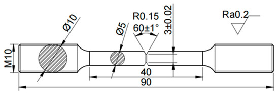
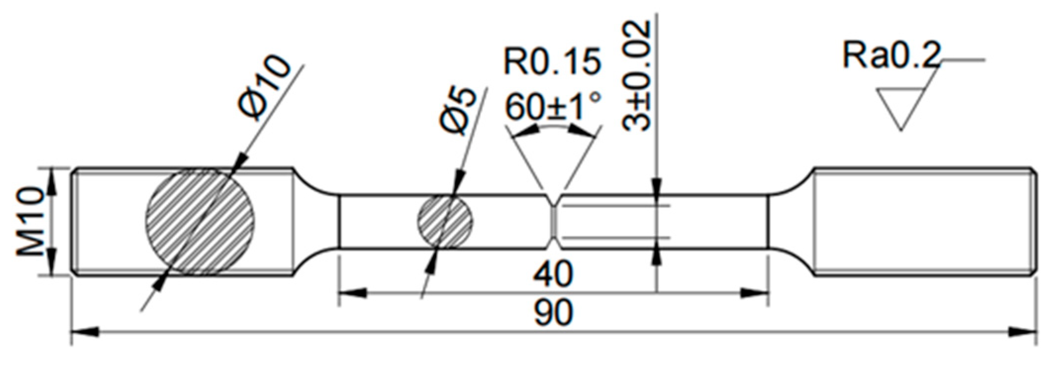
The dimensions of the slow-strain-rate tensile specimen are shown in Figure 1. The notched tensile specimens were hydrogen-charged in a 0.1 mol/L NaOH solution for 72 h at a current density of 4 mA/cm2 using an electrochemical workstation (Parstat 4000). To prevent hydrogen escape, the specimen surfaces were protected by electrochemical nickel plating. The notched tensile specimens were then mounted on a horizontal slow strain rate stress corrosion testing machine (YYF-50, SSRT, Hensgrand Co., Ltd., Jinan, China), and the slow strain rate tensile test program was started. The tensile rate was 0.005 mm/min. The strength loss ratio (LRs) and plasticity loss ratio (LRp) were calculated using the following equations:
where SN and SH are the ultimate tensile strengths of the uncharged and hydrogen-charged specimens, respectively, and DN and DH are the corresponding elongations. The fracture surfaces of the slow-strain-rate tensile specimens were observed using a Hitachi S-3400N field-emission scanning electron microscope.
LRs = (SN−SH)/SN × 100%
LRp = (DN−DH)/DN × 100%
Figure 1.
Schematic diagram of the specimen size for the notch tensile test.
3. Results
3.1. Microstructure
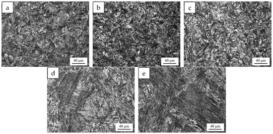
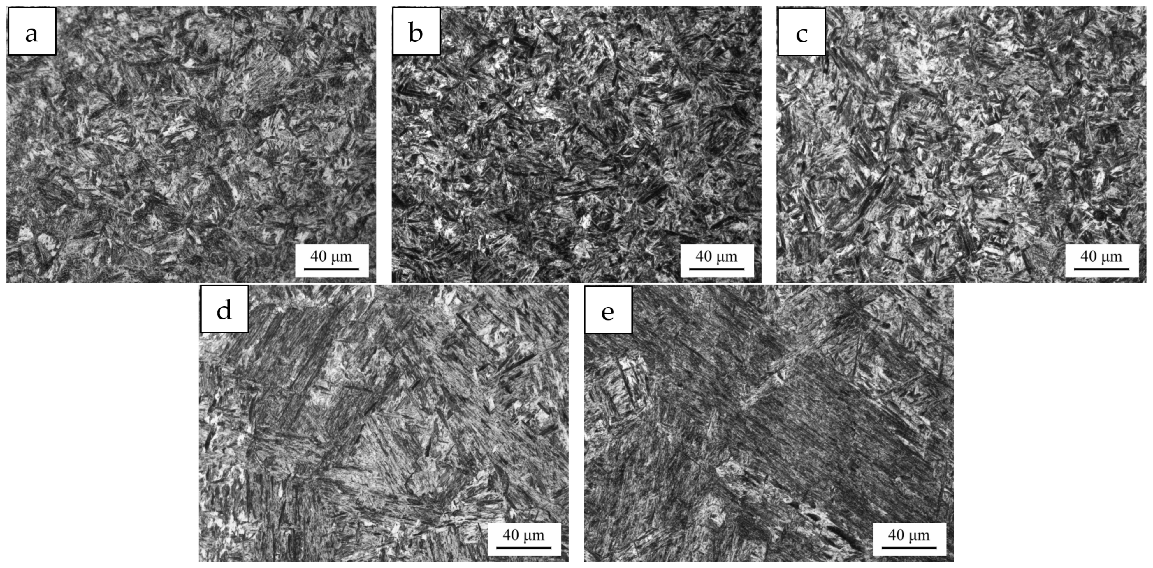
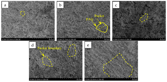
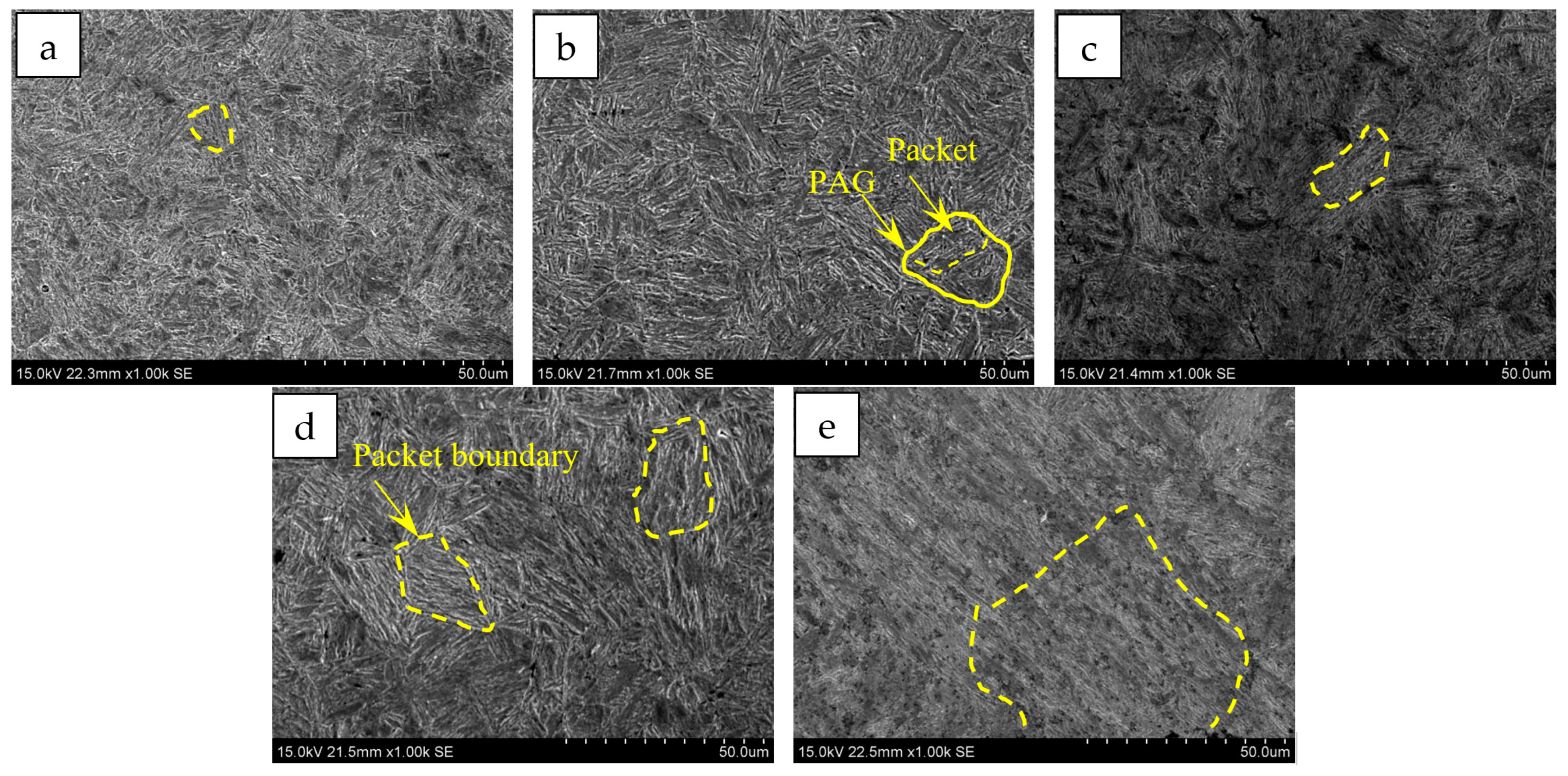
Specimens were taken from the experimental steels subjected to Q+T treatment at different quenching temperatures ranging from 850 to 1050 °C. The OM and SEM observations are shown in Figure 2 and Figure 3, and the quantitative results are listed in Table 2. After tempering at different quenching temperatures, all the experimental steels exhibited tempered lath martensitic microstructures. The bundle-like structure composed of martensite laths arranged in the same direction is referred to as the packet structure. As the quenching temperature increased from 850 °C to 1050 °C, the sizes of the PAGs and packet structures in the Q+T samples gradually increased.
Figure 2.
OM observation for Q+T samples subjected to different quenching temperatures. (a) 850 °C; (b) 900 °C; (c) 950 °C; (d) 1000 °C; (e) 1050 °C.
Figure 3.
SEM observation for Q+T samples subjected to different quenching temperatures. (a) 850 °C; (b) 900 °C; (c) 950 °C; (d) 1000 °C; (e) 1050 °C.
Table 2.
Quantitative characterization results of martensite microstructure of experimental steels subjected to different Q+T treatments.
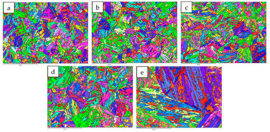
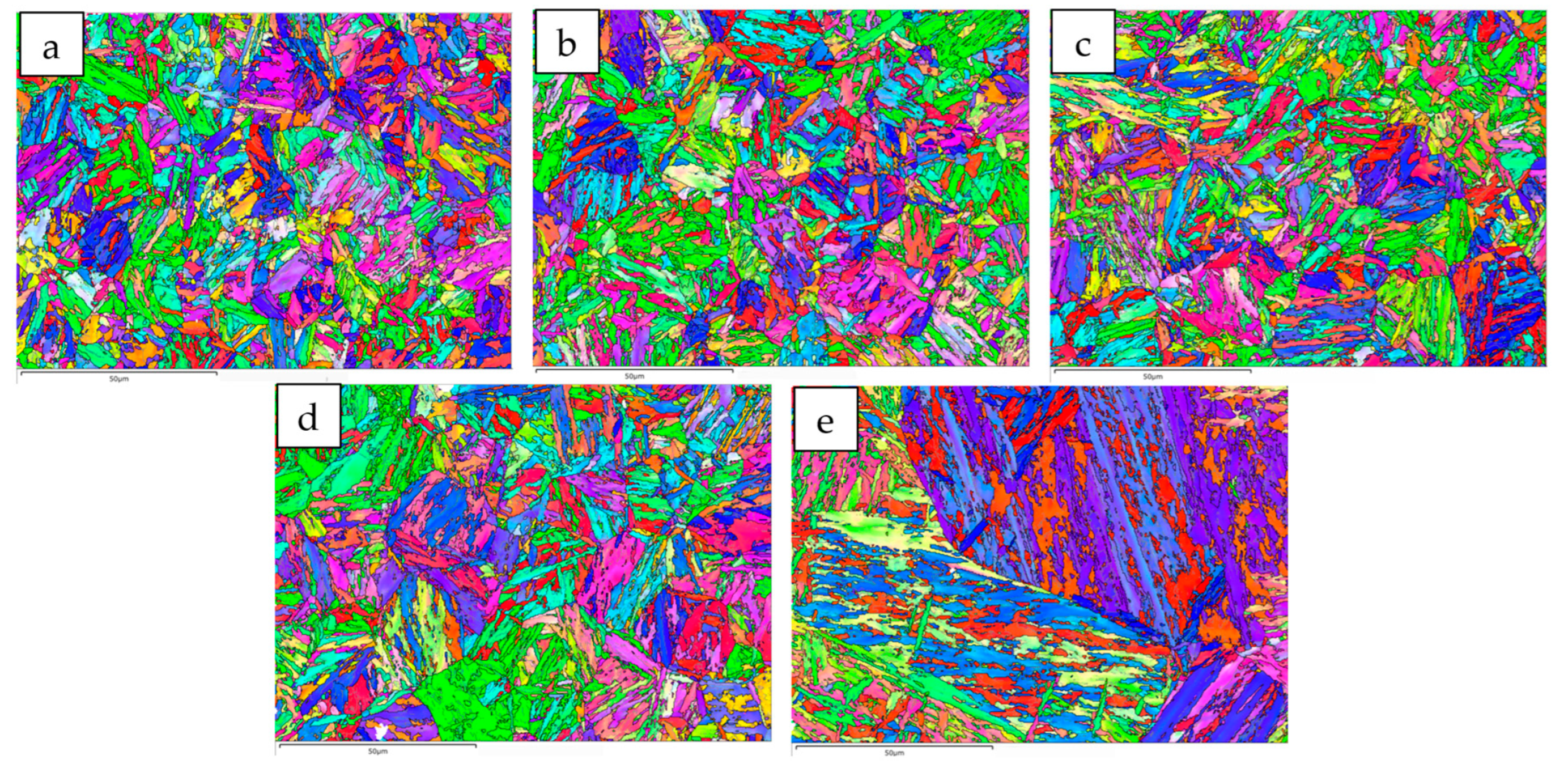
The EBSD analysis results of grain misorientation in the martensitic microstructure are shown in Figure 4. In Figure 4, the black lines represent grain boundaries with misorientation angles greater than 15°, while the white lines represent grain boundaries with misorientation angles between 2° and 15°. The PAG boundaries can be clearly observed. In addition, one or several packets exist within each PAG, and several martensite blocks with similar misorientations are present inside each packet.
Figure 4.
EBSD analysis for Q+T samples subjected to different quenching temperatures. (a) 850 °C; (b) 900 °C; (c) 950 °C; (d) 1000 °C; (e) 1050 °C.
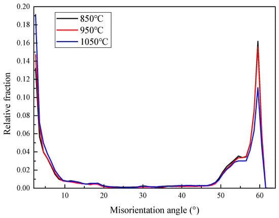
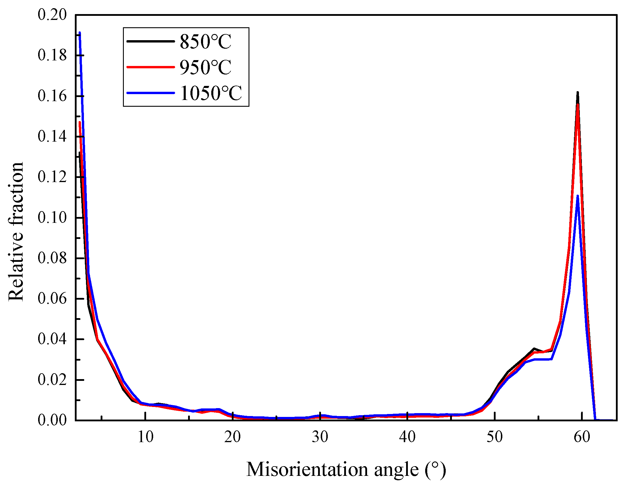
The quantitative results in Table 2 show that, as the quenching temperature increased from 850 °C to 1050 °C, the PAG size of the Q+T samples increased from 21.3 to 126.7 μm, the martensite packet size increased from 10.2 to 59.9 μm, and the block size increased from 2.6 to 5.8 μm. The single measurement misorientation values of PAG, packet, and block boundaries collected from different samples are listed in Table 3. The PAG boundaries were high-angle grain boundaries with misorientation angles ranging from 50° to 60°. The packet boundaries were also high-angle grain boundaries, with misorientation angles mainly in the ranges of 15–20° and 40–45°. In contrast, the block boundaries were low-angle grain boundaries with misorientation angles ranging from 2° to 15°. These boundaries jointly constituted the grain-boundary misorientation distribution shown in Figure 5. With increasing quenching temperature, the sizes of PAGs and packets gradually increased, while the fraction of high-angle grain boundaries decreased from 64.7% to 54.2%.
Table 3.
Single measurement misorientation values of PAG, packet, and block of experimental steels subjected to different Q+T treatments.
Figure 5.
Distribution of boundaries misorientation for Q+T samples subjected to different quenching temperatures.
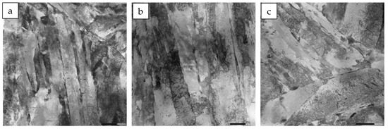
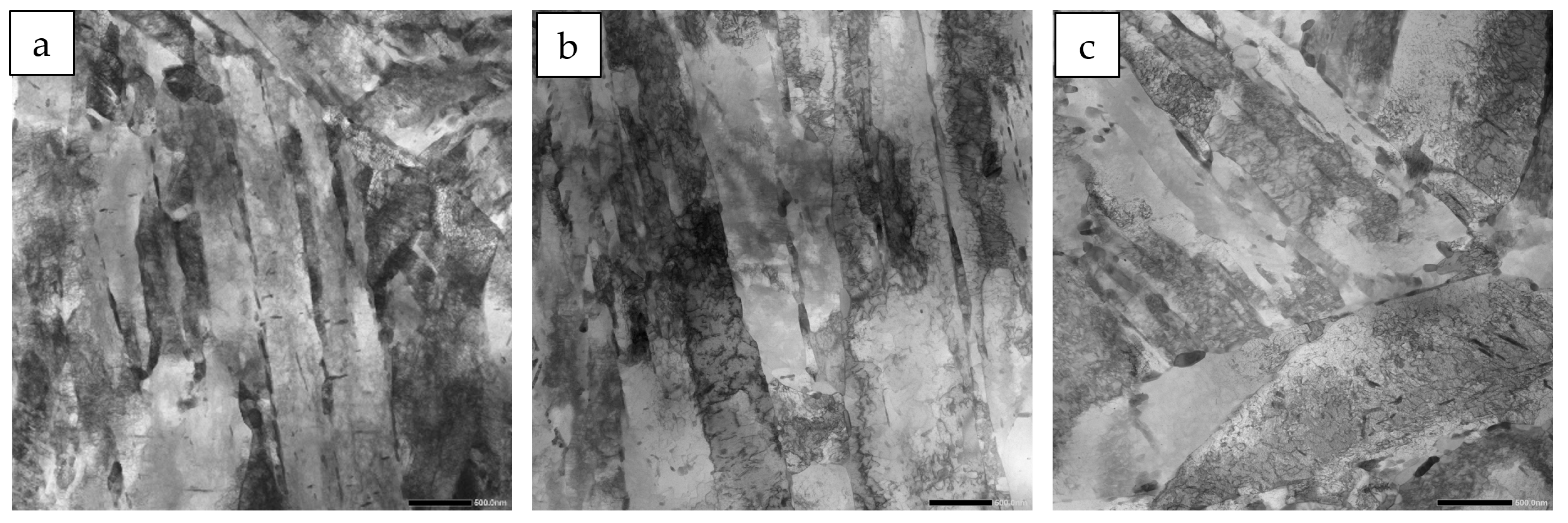
The TEM observations of the fine structure of the martensite are shown in Figure 6, and the quantitative results are listed in Table 2. As shown in Figure 6, the martensite laths were mainly elongated and arranged in a closely packed parallel manner. As the quenching temperature increased from 850 °C to 1050 °C, the martensite lath width of the Q+T samples increased from 0.30 μm to 0.38 μm.
Figure 6.
TEM observation for Q+T samples subjected to different quenching temperatures. (a) 850 °C; (b) 950 °C; (c) 1050 °C.
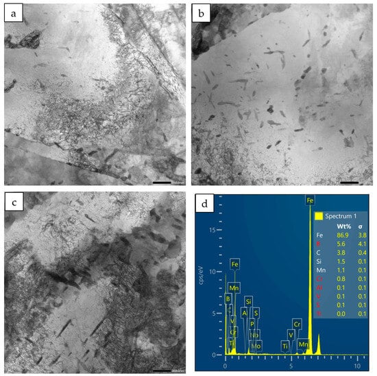
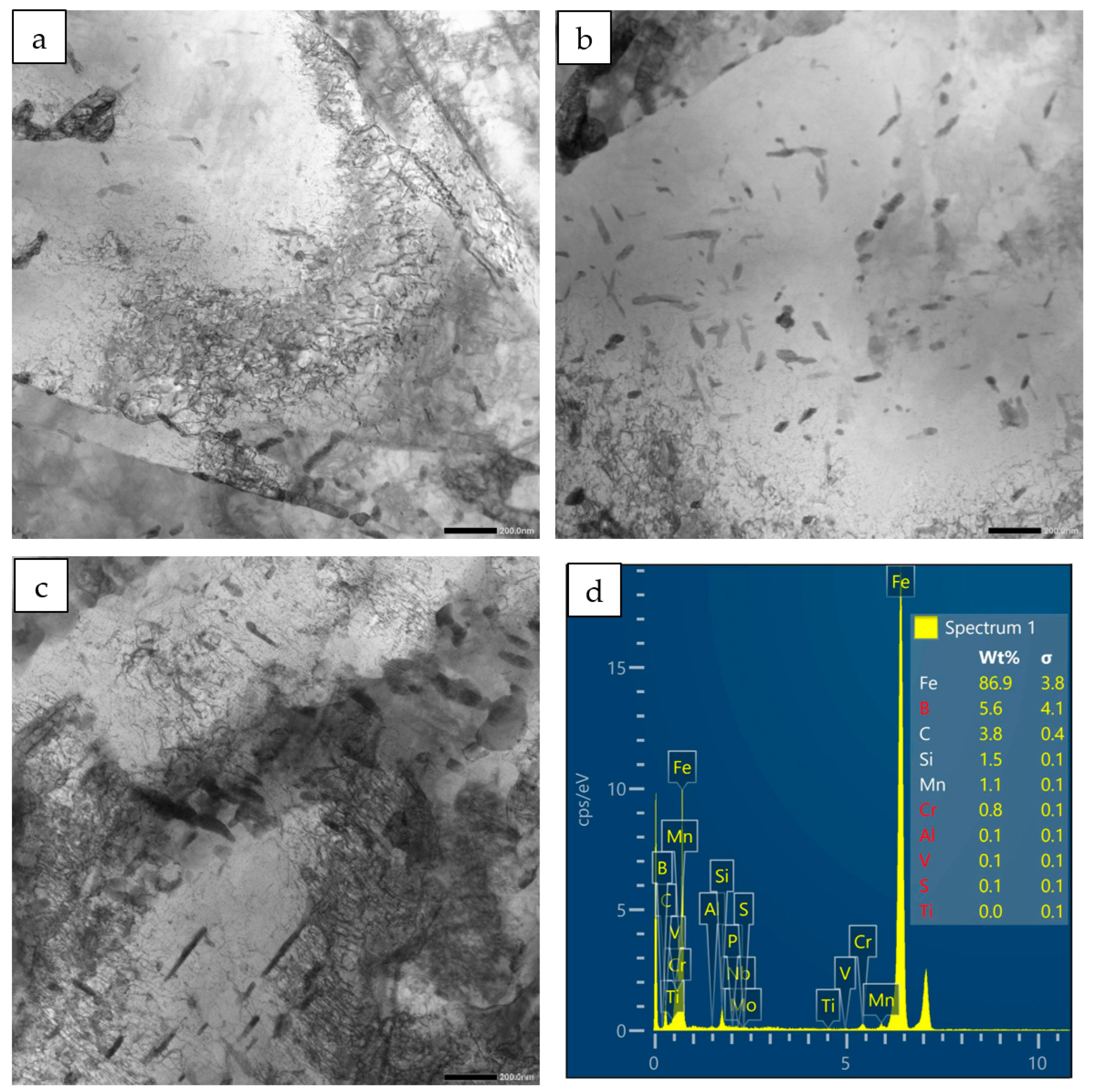
The morphology and distribution of carbides at typical quenching temperatures were observed by TEM, as shown in Figure 7. A large number of carbides were present in the steels after different Q+T treatments. With increasing quenching temperature, more carbon was dissolved into the matrix and subsequently diffused out from martensite during tempering, resulting in an increase in the number and size of carbides.
Figure 7.
TEM observation of carbides for Q+T samples subjected to different quenching temperatures. (a) 850 °C; (b) 950 °C; (c) 1050 °C; (d) the EDS of carbides.
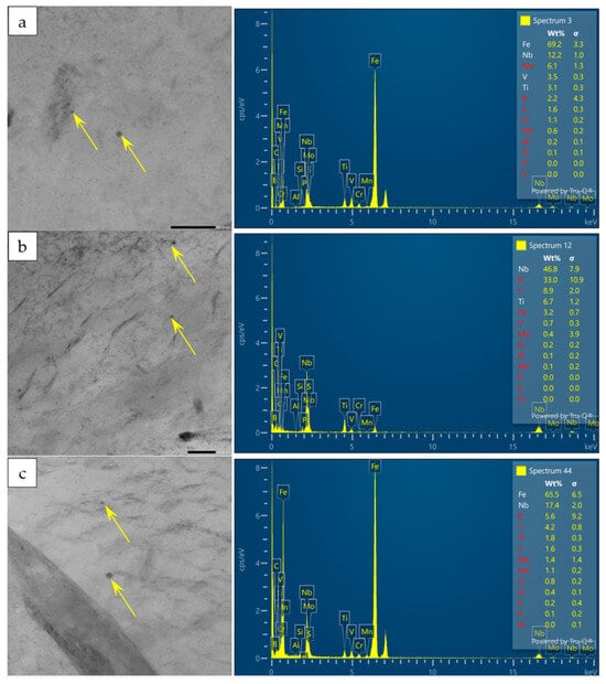
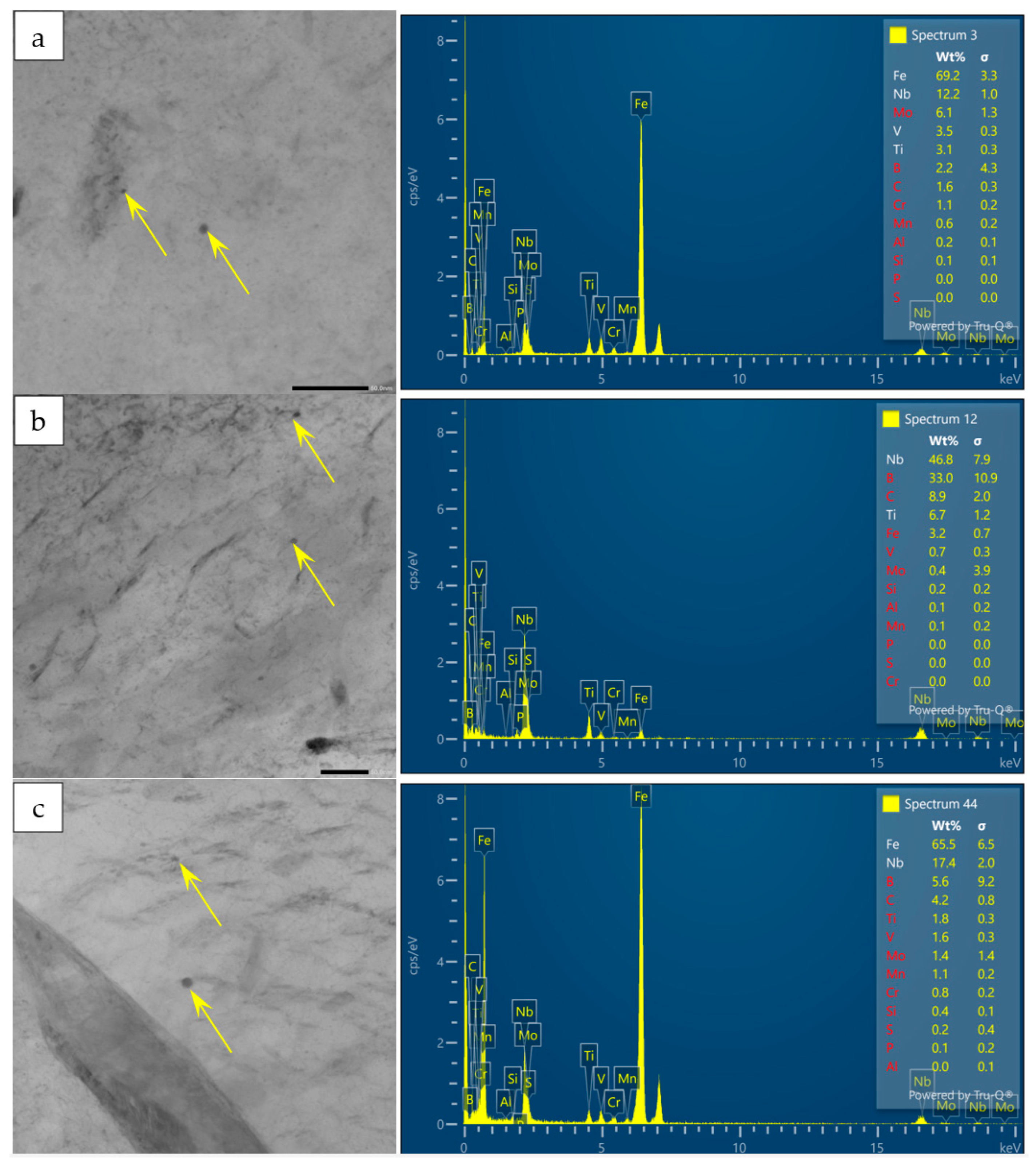
The precipitates at typical quenching temperatures were observed by TEM, as shown in Figure 8. After different Q+T treatments, the precipitates were all Nb-rich phases, including NbC, (Nb,Ti)C and (Nb,V,Ti)C, with sizes ranging from 2 to 8 nm. The quantitative results of the precipitates are listed in Table 2. With increasing quenching temperature, the type, number and size of the precipitates changed only slightly.
Figure 8.
TEM observation of precipitates for Q+T samples subjected to different quenching temperatures and the corresponding EDS. (a) 850 °C; (b) 950 °C; (c) 1050 °C.
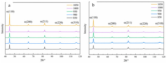
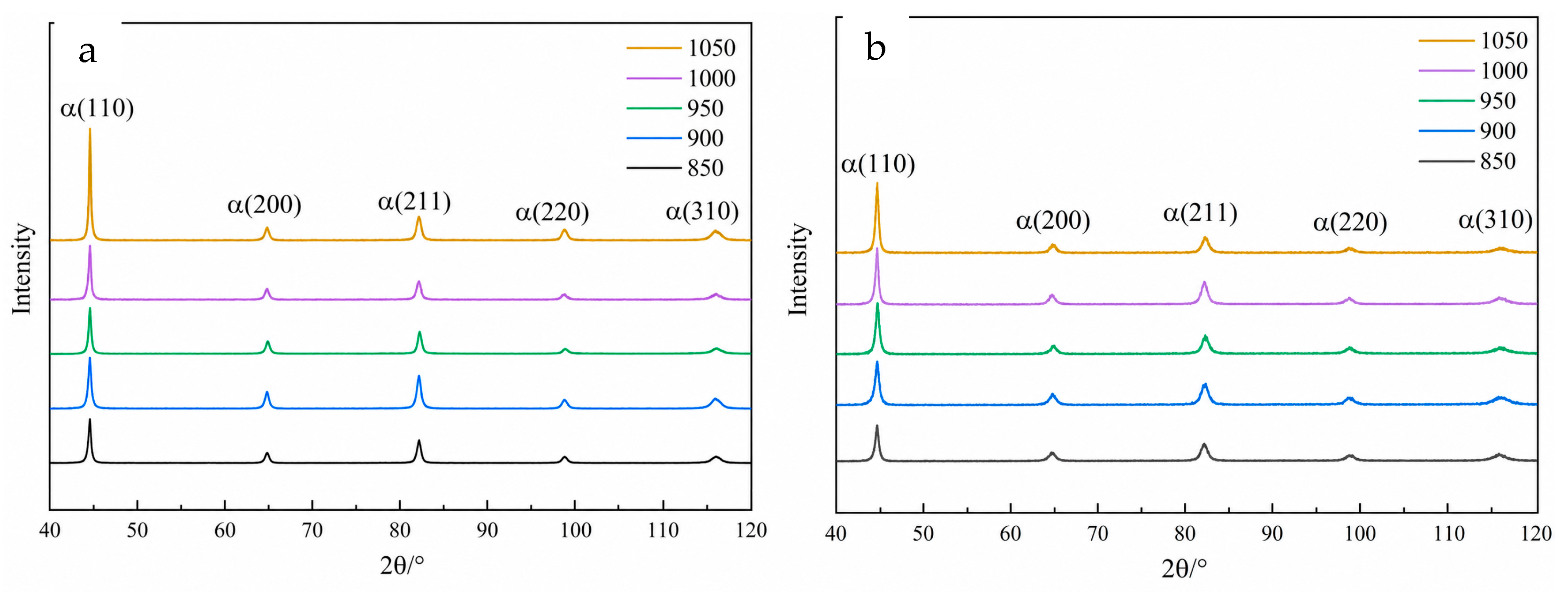
XRD was used to measure the dislocation density of the directly quenched samples and Q+T samples at different quenching temperatures. The obtained XRD patterns are shown in Figure 9, and the dislocation densities calculated from the XRD patterns are listed in Table 2. When the quenching temperature increased from 850 °C to 1050 °C, the dislocation density of the directly quenched samples increased from 5.51 × 10¹⁵ m−2 to 8.03 × 10¹⁵ m−2, while that of the Q+T-treated samples increased from 2.55 × 10¹⁵ m−2 to 2.88 × 10¹⁵ m−2. It should be noted that retained austenite may also influence the mechanical properties and hydrogen-assisted cracking behavior. However, no obvious austenite diffraction peaks were observed in the XRD patterns shown in Figure 9, suggesting that the retained austenite content was very limited or below the detection limit of XRD.
Figure 9.
X-ray diffraction analysis of quenched (a) and Q+T (b) samples subjected to different quenching temperatures.
3.2. Hydrogen Permeation and Slow Strain Rate Tensile
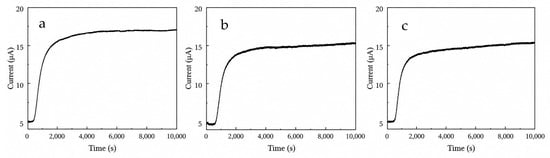
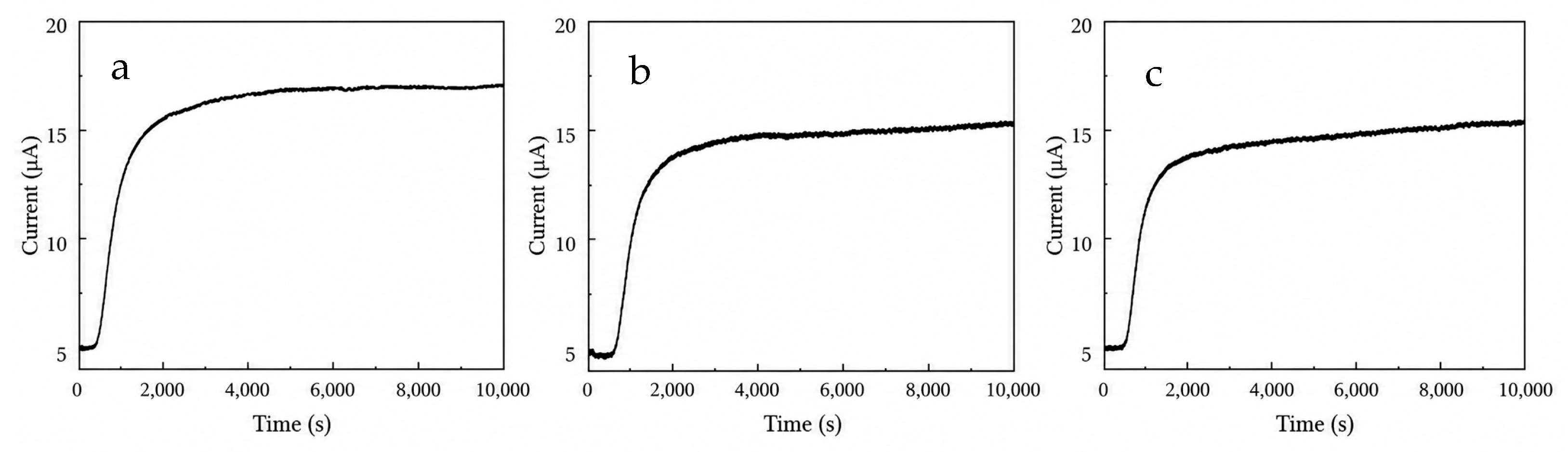
Hydrogen permeation tests were conducted on the Q+T steels at different quenching temperatures using a Devanathan–Stachurski double electrolytic cell. The measured hydrogen permeation curves are shown in Figure 10, and the corresponding effective hydrogen diffusion coefficient, Deff, is listed in Table 4. As the quenching temperature increased from 850 °C to 1050 °C, the hydrogen diffusion coefficient Deff increased from 1.05 × 10⁻⁶ cm2·s−1 to 3.21 × 10⁻⁶ cm2·s−1.
Figure 10.
Hydrogen permeation curves for Q+T samples subjected to different quenching temperatures. (a) 850 °C; (b) 950 °C; (c) 1050 °C.
Table 4.
Hydrogen diffusion coefficients and loss ratio of experimental steels subjected to different Q+T treatments.
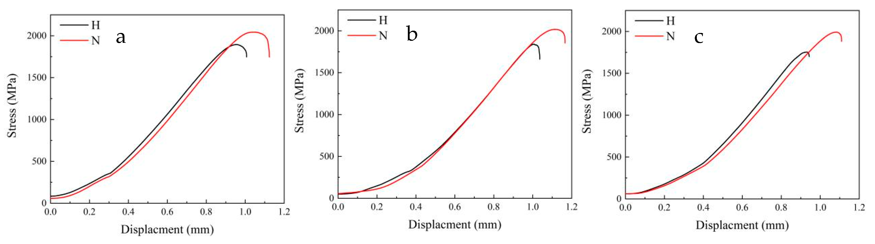
In Figure 11, the red and black curves correspond to the slow-strain-rate tensile curves of the experimental steels at different quenching temperatures under hydrogen-charged and uncharged conditions, respectively. Both strength and plasticity decreased after hydrogen charging. The strength and plasticity loss ratios of the samples subjected to Q+T treatment at different quenching temperatures were calculated, as listed in Table 4. As the quenching temperature increased from 850 °C to 1050 °C, the strength loss ratio (LRs) increased from 7.3% to 12.0%, and the plasticity loss ratio (LRp) increased from 10.0% to 13.6%. Therefore, the hydrogen-assisted cracking susceptibility of the experimental steel increased with increasing quenching temperature.
Figure 11.
Slow strain rate tensile curves for Q+T samples subjected to different quenching temperatures. (a) 850 °C; (b) 950 °C; (c) 1050 °C.
4. Discussion
4.1. The Influence of Quenching Temperature on the Microstructure
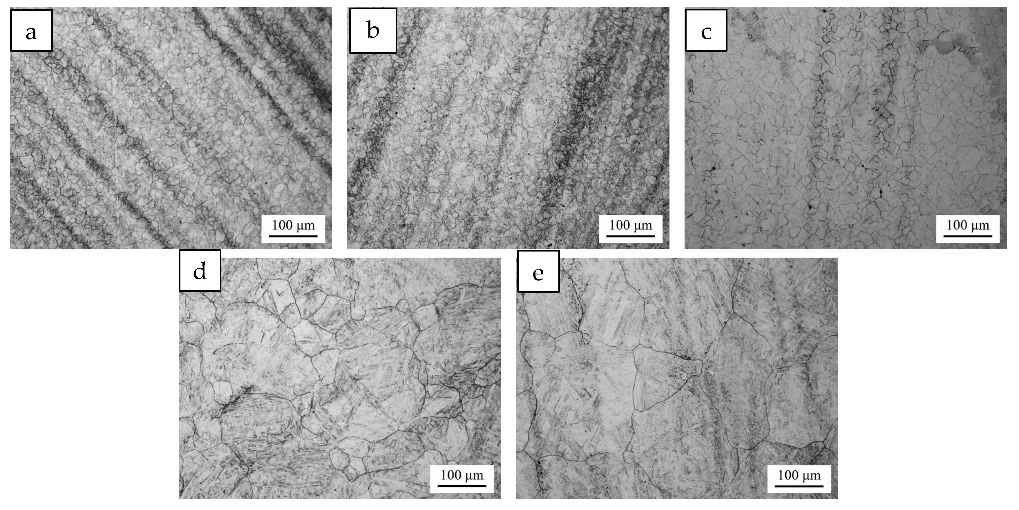
The PAGs of the samples quenched at different temperatures were observed, as shown in Figure 12. The quenching temperature significantly affected the morphology of the PAGs. When the quenching temperature was 850–950 °C, the PAGs were equiaxed and uniform in size. At a quenching temperature of 1000 °C, the PAGs remained equiaxed, but their size became nonuniform. When the quenching temperature reached 1050 °C, abnormal grain growth occurred. Overall, the PAGs grew markedly with increasing quenching temperature.
Figure 12.
OM observation of PAG for samples subjected to different quenching temperatures. (a) 850 °C; (b) 900 °C; (c) 950 °C; (d) 1000 °C; (e) 1050 °C.
The increase in the sizes of PAGs, martensite packets and martensite blocks with increasing quenching temperature can be explained as follows. As the quenching temperature increases from 850 °C to 1050 °C, the austenitizing temperature rises, leading to an exponential increase in the atomic diffusion coefficient and an accelerated grain-boundary migration rate [30]. With the increase in PAG size, the number of martensite variant nucleation sites during transformation is relatively reduced, while the growth space available for each packet becomes larger. In addition, the degree of freedom for variant selection decreases, promoting the increase in packet size with the coarsening of PAGs. A block is a group of variants with similar orientations within a packet. As the packet size increases, the number of blocks inside the packet may increase, or the transverse size of individual blocks may expand. At the same time, the coarsening of PAGs reduces the grain-boundary area per unit volume, weakening the restriction of neighboring variants on block growth; therefore, the block size also increases accordingly.
The increase in quenching temperature increased the contents of carbon and alloying elements dissolved in austenite, promoted more complete dissolution of carbides, intensified lattice distortion during martensitic transformation, and increased the dislocation density generated by transformation shear [31]. In addition, high-temperature quenching resulted in a large temperature difference between the specimen and the quenching medium, producing greater thermal stress and transformation stress during cooling (Figure 9a). During tempering, dislocations within martensite laths and at lath boundaries were merged and rearranged, leading to a significant decrease in dislocation density [32]. However, owing to the high initial dislocation density after high-temperature quenching and the longer dislocation slip distance in coarse martensite laths, dislocations were less likely to annihilate each other through cross-slip. Consequently, the dislocation density of the Q+T samples increased with increasing quenching temperature (Figure 9b).
With increasing quenching temperature, more carbon and alloying elements dissolved into austenite, forming supersaturated martensite after quenching. During tempering, carbon precipitated from the supersaturated solid solution, resulting in the formation of more carbides. Meanwhile, the dissolution of pre-existing carbides at high temperature increased the nucleation rate of re-precipitated carbides during tempering, ultimately increasing the total amount of carbides (Figure 7). At the same tempering temperature, a higher quenching temperature increased the defect density of the matrix and accelerated carbon diffusion, making carbides more likely to grow through Ostwald ripening during tempering; therefore, their average size increased [33]. As shown in Figure 8, the precipitates were Nb- and Ti-containing carbonitrides with extremely high thermal stability, and their complete dissolution may require temperatures higher than approximately 1265 °C, depending on the steel composition [34,35]. Within the range of 850–1050 °C, these precipitates underwent only partial dissolution, while most of the undissolved particles remained in the matrix. During rapid cooling after quenching, the small amount of dissolved microalloying elements had insufficient time to re-precipitate. During subsequent tempering, the relatively low temperature limited elemental diffusion, preventing the formation of new nano-precipitates. Therefore, the number of precipitates changed only slightly compared with the original state.
4.2. The Influence of Quenching Temperature on the Deff
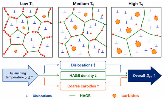
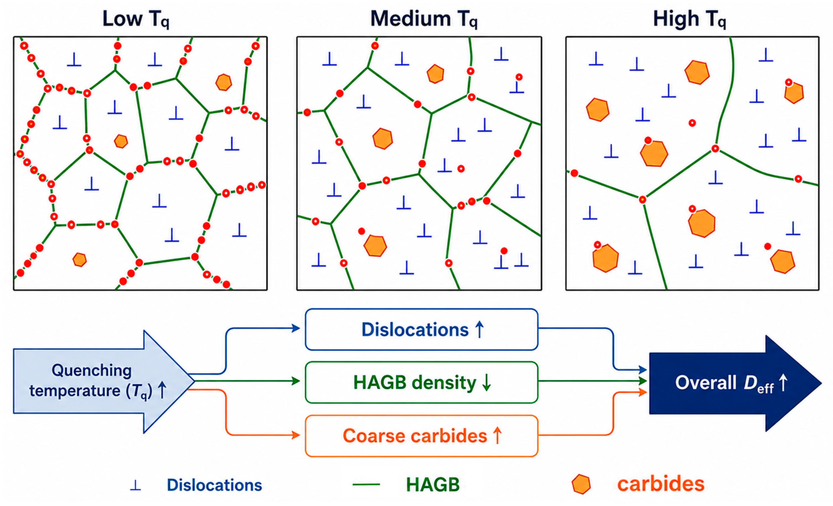
It is generally accepted that dislocations, grain boundaries and precipitates, as hydrogen traps, can capture hydrogen atoms; the larger the number of these traps, the lower the Deff. Dislocations are line defects with lattice distortion in their core regions and are typical reversible shallow traps [14,15,16]. Hydrogen atoms can be readily trapped by dislocations, but they can also desorb easily at room temperature and continue to diffuse. A high dislocation density provides a large number of shallow traps, increases the “residence time” of hydrogen atoms, and consequently reduces the measured Deff [16,21]. Therefore, with increasing quenching temperature, the increase in dislocation density is expected to exert a negative qualitative effect on the measured overall Deff.
Grain boundaries are planar defects and can be classified into low-angle grain boundaries and high-angle grain boundaries according to the misorientation angle. Their effects on hydrogen are significantly different. Low-angle grain boundaries are composed of dislocation arrays, and their hydrogen trapping behavior is similar to that of dislocations, corresponding to shallow traps. Hydrogen can diffuse relatively easily through low-angle grain boundaries, which are sometimes even regarded as fast diffusion paths. Therefore, low-angle grain boundaries have a limited effect on hindering hydrogen permeation and make a relatively small contribution to hydrogen embrittlement [14,15]. High-angle grain boundaries have disordered atomic arrangements and large free volume. They are usually regarded as deep or medium-depth traps and can strongly capture hydrogen. High-angle grain boundaries can also serve as fast diffusion paths [19,21]. Overall, grain boundaries mainly act as trapping sites and can significantly reduce Deff. With increasing quenching temperature, the density of high-angle grain boundaries decreases, which weakens the grain-boundary trapping effect and tends to promote an increase in the measured overall Deff.
The interface between precipitates and the matrix is a strong source of hydrogen traps, which is critical for controlling hydrogen embrittlement in modern high-strength steels, such as maraging steels and precipitation-strengthened steels [14,15]. The trapping characteristics depend on the interfacial state between the precipitates and the matrix. Coherent or semi-coherent interfaces, such as those associated with fine TiC and NbC particles, are usually irreversible deep traps, where hydrogen is difficult to escape once trapped. Dispersed nanoscale carbides/nitrides can capture a large amount of hydrogen and immobilize it in irreversible traps. Since a large amount of hydrogen is locked by deep traps, the macroscopically measured effective diffusion coefficient decreases [21,22]. In contrast, incoherent interfaces or large carbides may act as preferential sites for hydrogen accumulation and bubble formation. With increasing quenching temperature, the content and size of nano-precipitates change only slightly, whereas large carbides increase; therefore, the increased large carbides are expected to provide additional trapping sites and tend to reduce the measured overall Deff.
It should be emphasized that the D–S hydrogen permeation method only provides a combined effective hydrogen diffusion coefficient, and the individual effects of dislocations, grain boundaries and carbides cannot be quantitatively separated in this study. Therefore, Figure 13 is presented as a qualitative conceptual model rather than an experimental decomposition of Deff. Considering the combined effects of dislocations, grain boundaries and precipitates on hydrogen permeation behavior, the measured overall Deff shows an increasing trend with increasing quenching temperature. This is because high-angle grain boundaries and nano-precipitates act as strong hydrogen traps. As the quenching temperature increases, the nano-precipitates change only slightly, whereas the density of high-angle grain boundaries decreases significantly. Although the dislocation density and the number of large carbides increase, their diffusion-retarding effects are masked by the substantial loss of grain-boundary area caused by grain coarsening.
Figure 13.
Schematic diagram of the mechanism of Deff for Q+T samples subjected to different quenching temperatures.
4.3. The Influence of Quenching Temperature on the Hydrogen-Assisted Cracking Resistance
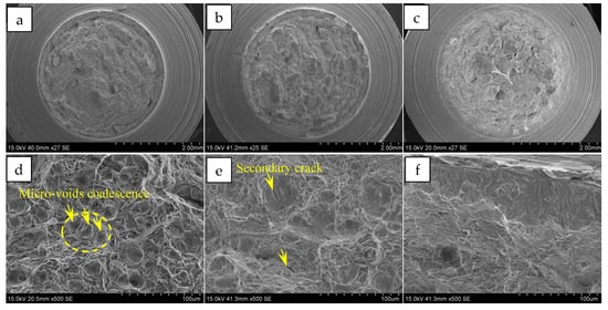
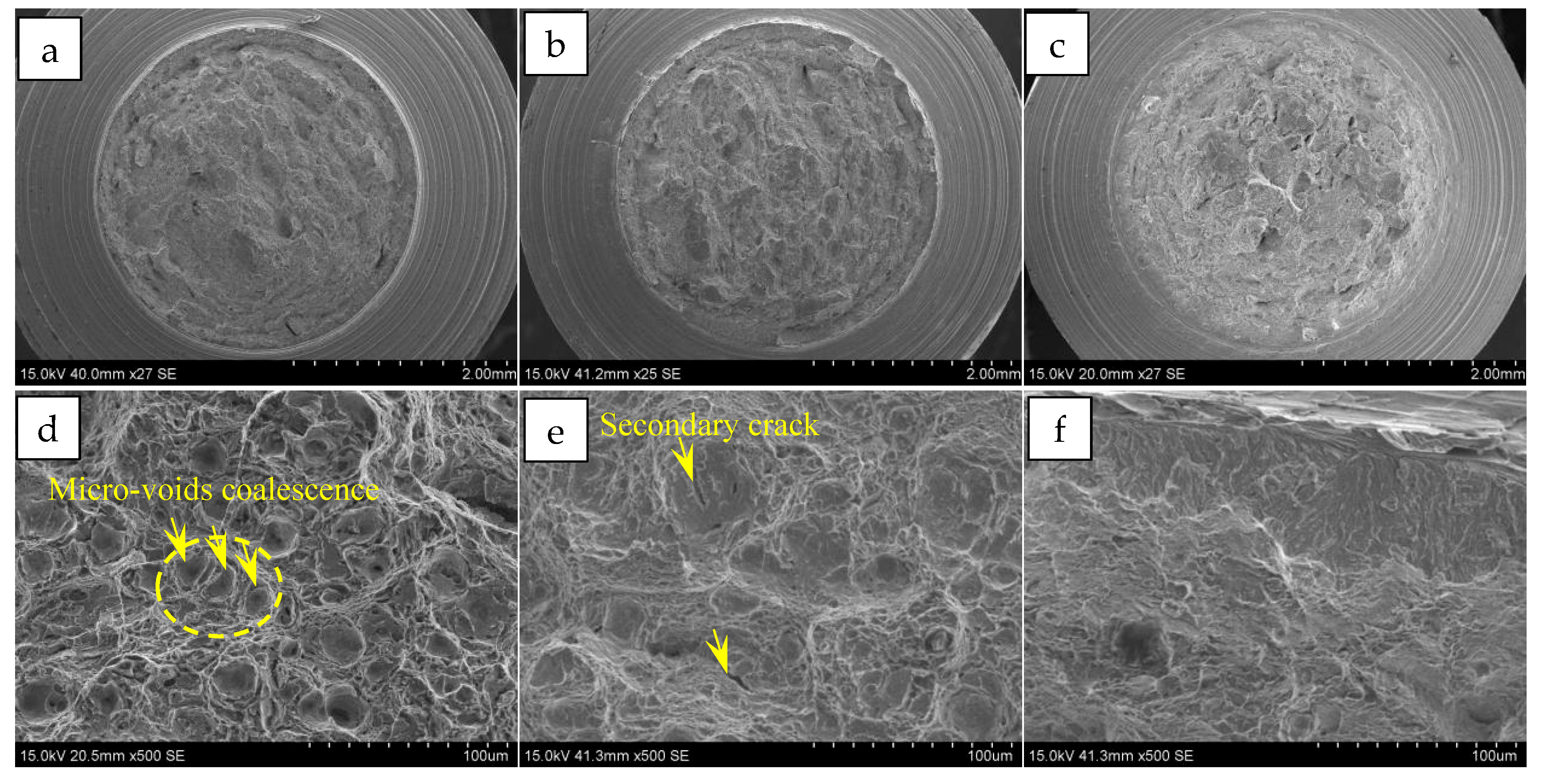
Figure 14 shows the fracture morphologies of the hydrogen-charged slow-strain-rate tensile specimens subjected to Q+T treatment at different quenching temperatures. Figure 14a–c show the macroscopic fracture morphologies, while Figure 14d–f show the fracture morphologies of the fibrous zones. When the quenching temperature was 850 °C, the fracture morphology of the fibrous zone was dominated by dimples. The dimples were relatively deep, and a tendency for dimple coalescence could also be observed, which was beneficial to improving the resistance of the steel to hydrogen-assisted cracking. When the quenching temperature was 950 °C, compared with the sample quenched at 850 °C, the dimples in the fibrous zone exhibited a larger size and a flatter morphology, and longitudinal secondary cracks were also observed. Tearing ridges with typical ductile fracture characteristics could also be observed at the edges of the flat dimples. When the quenching temperature was 1050 °C, the dimple depth further decreased, and quasi-cleavage fracture features began to appear on the fracture surface, which was related to the increase in grain size caused by the increase in quenching temperature.
Figure 14.
SEM observation of the fracture surface for samples subjected to different quenching temperatures. (a,d) 850 °C; (b,e) 950 °C; (c,f) 1050 °C.
Under the influence of hydrogen, the macroscopic fracture surface became flatter and the microscopic dimple depth gradually decreased with increasing quenching temperature, indicating that the fracture mechanism tended to transform from purely ductile fracture to ductile–brittle mixed fracture. Meanwhile, hydrogen reduced the local plastic deformation ability of the steel [27,28,36], limiting the extent of dimple deformation during tensile loading. As a result, cracks were more likely to propagate rapidly through hydrogen-enriched regions, preventing the sufficient formation of large and deep dimples.
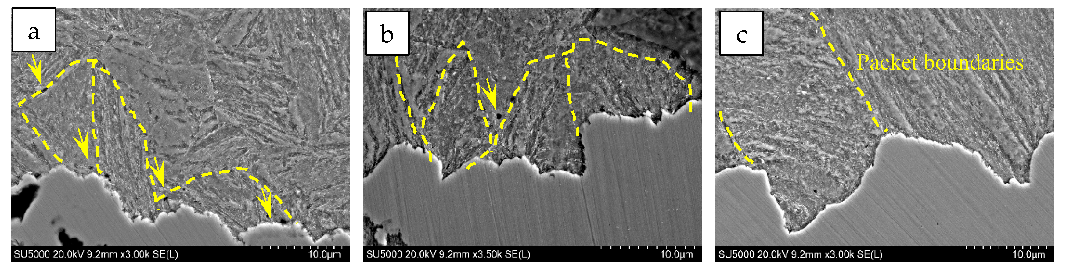
Figure 15 shows SEM observation of cross-sectional cracks in the slow-strain-rate tensile specimens of the experimental steels subjected to Q+T treatment at different quenching temperatures. It can be seen that packet boundaries indicated by the yellow lines can deflect cracks during propagation, and previous studies have also suggested that packets are the main microstructural controlling units that hinder the crack propagation [37]. With increasing quenching temperature, the frequency of crack deflection decreased significantly, mainly due to the coarsening of packets at higher quenching temperatures. Notably, in the Q+T sample quenched at 850 °C, the crack exhibited a zigzag morphology within a propagation unit. A large number of microvoids appeared in the surrounding matrix, as indicated by the yellow arrows, accompanied by slight plastic deformation. This indicates that, during tensile deformation, local inhomogeneous plastic deformation promoted the nucleation and growth of microvoids, followed by deflected crack propagation through microvoid coalescence.
Figure 15.
SEM observation of cross-sectional cracks for samples subjected to different quenching temperatures. (a) 850 °C; (b) 950 °C; (c) 1050 °C.
With increasing quenching temperature, this zigzag propagation mode gradually became straighter. In the Q+T sample quenched at 1050 °C, the crack exhibited an approximately continuous straight-line morphology, indicating a brittle cleavage-like crack propagation feature. This is because the increase in grain size and the decrease in total grain-boundary area reduce the obstacles encountered during crack propagation and lower the crack propagation resistance. As a result, cracks can propagate rapidly along certain crystallographic planes, tending to form cleavage fracture surfaces.
5. Conclusions
For high-strength quenched and tempered bolt steel, the effect of quenching temperature on microstructural evolution, hydrogen diffusion behavior, and hydrogen-assisted cracking resistance was investigated. The main conclusions are as follows:
- (1)
- Increasing the quenching temperature from 850 °C to 1050 °C caused significant coarsening of prior austenite grains, packets, and blocks. Meanwhile, the fraction of high-angle grain boundaries decreased, while carbides became more numerous and coarser, and the dislocation density increased.
- (2)
- The hydrogen diffusion behavior was controlled by the competing effects of different hydrogen-trapping microstructural features. The increased dislocation density and carbide population tended to reduce Deff, whereas grain coarsening and the reduced high-angle grain boundary area promoted hydrogen diffusion. The dominant effect of the reduced high-angle grain boundary area resulted in an overall increase in Deff with increasing quenching temperature.
- (3)
- The increased quenching temperature deteriorated the resistance of the tested steel to hydrogen-assisted cracking. The strength loss ratio and plasticity loss ratio increased after hydrogen charging, indicating enhanced hydrogen embrittlement susceptibility. Meanwhile, the fracture morphology changed from deep dimples to flatter dimples and flattened ductile–brittle mixed fracture features.
- (4)
- This study reveals that the hydrogen-assisted cracking resistance of high-strength quenched and tempered bolt steel is governed by the balance between hydrogen-trapping sites and effective hydrogen diffusion paths. Controlling the prior austenite grain size and preserving sufficient high-angle grain boundary area are therefore important for improving hydrogen embrittlement resistance.
Author Contributions
Conceptualization, H.W. and G.S.; methodology, G.S. and S.W.; validation, H.W., G.S. and X.X.; formal analysis, X.X. and Q.W.; investigation, Y.D.; resources, X.X. and Q.W.; data curation, Y.D.; writing—original draft preparation, H.W.; writing—review and editing, G.S. and S.W.; supervision, X.X.; project administration, Q.W.; funding acquisition, Q.W. All authors have read and agreed to the published version of the manuscript.
Funding
This research was funded by the S&T Program of Hebei, grant number 23311002L.
Data Availability Statement
The original contributions presented in this study are included in the article. Further inquiries can be directed to the corresponding author.
Conflicts of Interest
Authors Hui Wen and Xiaochun Xu were employed by the company Research Institute of Nanjing Iron & Steel Co., Ltd. The remaining authors declare that the research was conducted in the absence of any commercial or financial relationships that could be construed as a potential conflict of interest.
References
- Kubota, M.; Tarui, T.; Yamasaki, S.; Ochi, T. Development of High-Strength Steels for Bolts. Nippon Steel Tech. Rep. 2005, 91, 62–66. [Google Scholar]
- Liu, J.; Zhao, F.; Shi, W.; Dong, H.; Guo, X. Enhanced Hydrogen Embrittlement Resistance in a Vanadium-Alloyed 42CrNiMoV Steel for High-Strength Wind Turbine Bolts. Acta Metall. Sin. Engl. Lett. 2025, 38, 2300–2315. [Google Scholar] [CrossRef] [Scilit]
- Azuma, K.; Chida, T.; Tarui, T.; Matsuishi, N.; Okada, T. Development of Super High-Strength Bolts with Tensile Strengths of 1600 to 2000 N/Mm2. Int. J. Steel Struct. 2009, 9, 291–299. [Google Scholar] [CrossRef] [Scilit]
- Li, Z.; Gan, Y.; Shao, P.; Xu, X.; Li, X. Influence of Atmospheric Environment on Corrosion and Rate Prediction of High-Strength Bolts Using GBRT and SHAP Analysis. Structures 2026, 88, 111815. [Google Scholar] [CrossRef] [Scilit]
- Omura, T. Hydrogen Entry and Its Effect on Delayed Fracture Susceptibility of High Strength Steel Bolts under Atmospheric Corrosion. ISIJ Int. 2012, 52, 267–273. [Google Scholar] [CrossRef] [Scilit]
- Tada, M.; Kikuchi, K.; Tomita, K.; Shiraga, T. Hydrogen Absorption and Desorption of Steel in the High Strength Bolt Manufacturing. ISIJ Int. 2012, 52, 281–285. [Google Scholar] [CrossRef] [Scilit]
- Shibata, A.; Takeda, Y.; Kimura, Y.; Tsuji, N. Hydrogen-Related Fracture Behavior under Constant Loading Tensile Test in As-Quenched Low-Carbon Martensitic Steel. Metals 2022, 12, 440. [Google Scholar] [CrossRef] [Scilit]
- Lv, W.; Yu, W.; Wu, Z.; Yan, Y.; Shi, J.; Wang, M. Hydrogen Embrittlement Susceptibility of a Newly Developed Grain-Refined Ultra-High Strength Steel. Materials 2025, 18, 987. [Google Scholar] [CrossRef] [Scilit] [PubMed]
- Clarke, A.J.; Klemm-Toole, J.; Clarke, K.D.; Coughlin, D.R.; Pierce, D.T.; Euser, V.K.; Poplawsky, J.D.; Clausen, B.; Brown, D.; Almer, J.; et al. Perspectives on Quenching and Tempering 4340 Steel. Metall. Mater. Trans. A 2020, 51, 4984–5005. [Google Scholar] [CrossRef] [Scilit]
- Hidalgo, J.; Santofimia, M.J. Effect of Prior Austenite Grain Size Refinement by Thermal Cycling on the Microstructural Features of As-Quenched Lath Martensite. Metall. Mater. Trans. A 2016, 47, 5288–5301. [Google Scholar] [CrossRef] [Scilit]
- Tong, Z.; Wang, H.; Zheng, W.; Zhou, H. Change in Hydrogen Trapping Characteristics and Influence on Hydrogen Embrittlement Sensitivity in a Medium-Carbon, High-Strength Steel: The Effects of Heat Treatments. Materials 2024, 17, 1854. [Google Scholar] [CrossRef] [Scilit] [PubMed]
- Cupertino-Malheiros, L.; Oudriss, A.; Thébault, F.; Piette, M.; Feaugas, X. Hydrogen Diffusion and Trapping in Low-Alloy Tempered Martensitic Steels. Metall. Mater. Trans. A 2023, 54, 1159–1173. [Google Scholar] [CrossRef] [Scilit]
- Barrera, O.; Bombac, D.; Chen, Y.; Daff, T.D.; Galindo-Nava, E.; Gong, P.; Haley, D.; Horton, R.; Katzarov, I.; Kermode, J.R.; et al. Understanding and Mitigating Hydrogen Embrittlement of Steels: A Review of Experimental, Modelling and Design Progress from Atomistic to Continuum. J. Mater. Sci. 2018, 53, 6251–6290. [Google Scholar] [CrossRef] [Scilit] [PubMed]
- Li, X.; Zhang, J.; Cui, Y.; Djukic, M.B.; Feng, H.; Wang, Y. Review of the Hydrogen Embrittlement and Interactions between Hydrogen and Microstructural Interfaces in Metallic Alloys: Grain Boundary, Twin Boundary, and Nano-Precipitate. Int. J. Hydrogen Energy 2024, 72, 74–109. [Google Scholar] [CrossRef] [Scilit]
- McCarroll, I.E.; Lin, Y.-C.; Rosenthal, A.; Yen, H.-W.; Cairney, J.M. Hydrogen Trapping at Dislocations, Carbides, Copper Precipitates and Grain Boundaries in a Dual Precipitating Low-Carbon Martensitic Steel. Scr. Mater. 2022, 221, 114934. [Google Scholar] [CrossRef] [Scilit]
- Oriani, R.A. The Diffusion and Trapping of Hydrogen in Steel. Acta Metall. 1970, 18, 147–157. [Google Scholar] [CrossRef] [Scilit]
- Lan, X.; Okada, K.; Ueji, R.; Shibata, A. Enhancing Hydrogen Embrittlement Resistance in High-Strength Martensitic Steels via Tailoring Variant Selection at Prior Austenite Grain Boundaries. Scr. Mater. 2026, 274, 117157. [Google Scholar] [CrossRef] [Scilit]
- Du, D.H.; Zhang, Y.; Geng, Z.Y.; He, B.B.; Huang, M.X. Improving the Hydrogen Embrittlement Property of 1.8 GPa Press-Hardened Steel by Controlling the Prior Austenite Grain Size. Metall. Mater. Trans. A 2024, 55, 2940–2951. [Google Scholar] [CrossRef] [Scilit]
- Zhou, X.; Marchand, D.; McDowell, D.L.; Zhu, T.; Song, J. Chemomechanical Origin of Hydrogen Trapping at Grain Boundaries in Fcc Metals. Phys. Rev. Lett. 2016, 116, 075502. [Google Scholar] [CrossRef] [Scilit] [PubMed]
- Hirth, J.P. Effects of Hydrogen on the Properties of Iron and Steel. Metall. Trans. A 1980, 11, 861–890. [Google Scholar] [CrossRef] [Scilit]
- Pressouyre, G.M. A Classification of Hydrogen Traps in Steel. Metall. Trans. A 1979, 10, 1571–1573. [Google Scholar] [CrossRef] [Scilit]
- Kim, S.-G.; Kim, J.-Y.; Hwang, B. Effect of Tempering Temperature on Hydrogen Embrittlement of SCM440 Tempered Martensitic Steel. Materials 2023, 16, 5709. [Google Scholar] [CrossRef] [Scilit] [PubMed]
- Hagihara, Y. Evaluation of Delayed Fracture Characteristics of High-Strength Bolt Steels by CSRT. ISIJ Int. 2012, 52, 292–297. [Google Scholar] [CrossRef] [Scilit]
- Zhao, X.; Zhang, C.; Zhang, Y.; Hui, W.; Zhao, X. Hydrogen-Induced Delayed Fracture of Cu-Containing High-Strength Bolt Steel. J. Iron Steel Res. Int. 2023, 30, 375–383. [Google Scholar] [CrossRef] [Scilit]
- Zhang, C.; Hui, W.; Zhao, X.; Zhang, Y.; Zhao, X. The Potential Significance of Microalloying with Nb in Enhancing the Resistance to Hydrogen-Induced Delayed Fracture of 1300-MPa-Grade High-Strength Bolt Steel. Eng. Fail. Anal. 2022, 135, 106144. [Google Scholar] [CrossRef] [Scilit]
- Zhang, C.; Liu, Y.; Jiang, C.; Xiao, J. Effects of Niobium and Vanadium on Hydrogen-Induced Delayed Fracture in High Strength Spring Steel. J. Iron Steel Res. Int. 2011, 18, 49–53. [Google Scholar] [CrossRef] [Scilit]
- Nagao, A.; Smith, C.D.; Dadfarnia, M.; Sofronis, P.; Robertson, I.M. The Role of Hydrogen in Hydrogen Embrittlement Fracture of Lath Martensitic Steel. Acta Mater. 2012, 60, 5182–5189. [Google Scholar] [CrossRef] [Scilit]
- Song, J.; Curtin, W.A. Atomic Mechanism and Prediction of Hydrogen Embrittlement in Iron. Nat. Mater. 2013, 12, 145–151. [Google Scholar] [CrossRef] [Scilit] [PubMed]
- Wan, L.; Geng, W.T.; Ishii, A.; Du, J.-P.; Mei, Q.; Ishikawa, N.; Kimizuka, H.; Ogata, S. Hydrogen Embrittlement Controlled by Reaction of Dislocation with Grain Boundary in Alpha-Iron. Int. J. Plast. 2019, 112, 206–219. [Google Scholar] [CrossRef] [Scilit]
- Yue, C.; Zhang, L.; Liao, S.; Gao, H. Kinetic Analysis of the Austenite Grain Growth in GCr15 Steel. J. Mater. Eng. Perform. 2010, 19, 112–115. [Google Scholar] [CrossRef] [Scilit]
- Allain, S.; Bouaziz, O.; Takahashi, M. Toward a New Interpretation of the Mechanical Behaviour of As-Quenched Low Alloyed Martensitic Steels. ISIJ Int. 2012, 52, 717–722. [Google Scholar] [CrossRef] [Scilit]
- Pešička, J.; Kužel, R.; Dronhofer, A.; Eggeler, G. The Evolution of Dislocation Density during Heat Treatment and Creep of Tempered Martensite Ferritic Steels. Acta Mater. 2003, 51, 4847–4862. [Google Scholar] [CrossRef] [Scilit]
- Ju, Y.L.; Goodall, A.; Davis, C.; Strangwood, M. Characterisation of Precipitation and Coarsening of Carbides during Tempering in a Low Alloyed Quenched and Tempered Steel. Mater. Sci. Forum 2018, 941, 33–38. [Google Scholar] [CrossRef] [Scilit]
- Webel, J.; Mohrbacher, H.; Detemple, E.; Britz, D.; Mücklich, F. Quantitative Analysis of Mixed Niobium-Titanium Carbonitride Solubility in HSLA Steels Based on Atom Probe Tomography and Electrical Resistivity Measurements. J. Mater. Res. Technol. 2022, 18, 2048–2063. [Google Scholar] [CrossRef] [Scilit]
- Xing, L.; Guo, J.; Li, X.; Zhang, Z.; Wang, M.; Bao, Y.; Zeng, F.; Chen, B. Control of TiN Precipitation Behavior in Titanium-Containing Micro-Alloyed Steel. Mater. Today Commun. 2020, 25, 101292. [Google Scholar] [CrossRef] [Scilit]
- Wang, M.; Akiyama, E.; Tsuzaki, K. Effect of Hydrogen on the Fracture Behavior of High Strength Steel during Slow Strain Rate Test. Corros. Sci. 2007, 49, 4081–4097. [Google Scholar] [CrossRef] [Scilit]
- Guo, C.; Hao, L.; Li, S.; Kang, Y.; An, Y. Effect of Lath Martensite Submicrostructure on Mechanical Properties and Crack Propagation Behaviour by In-Situ Tension in 0.09C–1.7Mn–0.6Cr Steel. Fatigue Fract. Eng. Mater. Struct. 2020, 43, 2550–2559. [Google Scholar] [CrossRef] [Scilit]

Disclaimer/Publisher’s Note: The statements, opinions and data contained in all publications are solely those of the individual author(s) and contributor(s) and not of MDPI and/or the editor(s). MDPI and/or the editor(s) disclaim responsibility for any injury to people or property resulting from any ideas, methods, instructions or products referred to in the content. |
© 2026 by the authors. Licensee MDPI, Basel, Switzerland. This article is an open access article distributed under the terms and conditions of the Creative Commons Attribution (CC BY) license.