


Abstract
A vertical-type high-speed twin-roll caster can cast strips at a speed of 60 m/min. However, ripple marks, which are typical surface defects on strips cast using a twin-roll caster, also appear on strips cast using this caster. In the present study, Al-5%Mg was used because severe ripple marks occur on Al-5%Mg strips. The influences of the molten-metal head (50, 100, and 150 mm), which is a characteristic parameter for this caster, the molten-metal temperature (645, 685, and 735 °C), and the nozzle thickness on ripple marks were investigated. The nozzle thickness was an important factor in eliminating ripple marks, and a nozzle thickness of 3 mm was suitable for eliminating them. No relationship was found between ripple marks and surface cracks. The surface cracks decreased as the roll load decreased, and a roll load of 5 N/mm was suitable. Based on the obtained results, the optimum nozzle shape and casting conditions for casting strips without ripple marks or cracks were clarified.
1. Introduction
A twin-roll caster (TRC) can cast strips directly from molten metal in a single process [1], which has the advantage of reducing process complexity and saving energy. A disadvantage of a conventional twin-roll caster for aluminum alloys (CTRCA) is its low productivity due to its slow roll speed [2,3,4,5]. Increasing the roll speed can improve productivity, which also leads to energy savings. A vertical-type high-speed twin-roll caster (VHSTRC) was developed to increase the roll speed [6,7]. In developing the VHSTRC, attention was paid to the roll material, the use of a parting material on the roll, and the molten-metal head. The roll material for a CTRCA is steel for hot rolling, whereas that for a VHSTRC is a copper alloy for rapid solidification and an increased roll speed. A parting material is used in a CTRCA to prevent the strip from sticking to the roll, but it is not required in a VHSTRC because the strip does not stick to the copper alloy roll.
Ripple marks are typical surface defects in strips cast using a TRC, and preventing their occurrence is very important. In a CTRCA, the molten-metal head is set at a lower position to reduce ripple marks [3,4]. In a VHSTRC, the molten-metal head is set at a position higher than 50 mm to improve the contact between the roll and the molten aluminum alloy. The cooling ability of a VHSTRC is better than that of a CTRCA because of this setup; as a result, the roll speed for a VHSTRC is higher than that for a CTRCA. In general, the roll speed for a CTRCA is lower than 5 m/min [8,9,10,11,12,13], whereas that for a VHSTRC is higher than 20 m/min [6,7]. There are many differences between a CTRCA and a VHSTRC in terms of the casting process. There have been several reports concerning ripple marks on strip cast using a CTRCA [14,15,16,17,18]. It is predicted that the ripple marks and the casting conditions that influence ripple marks in a VHSTRC [19] are different from those in a CTRCA [2]. The casting conditions that may influence ripple marks in a VHSTRC are as follows: roll speed, molten-metal head, molten-metal temperature, roll material, and parting material. A higher roll speed is the most important characteristic of a VHSTRC, so it would not be meaningful if ripple marks were suppressed only at lower speeds. The roll speed in this study was set at 60 m/min. A copper alloy roll with no parting material was generally used to increase the roll speed in the VHSTRC. The molten-metal head and the molten-metal temperature are adjustable and fundamental conditions. The effects of these conditions on ripple marks have not been clarified; therefore, they were investigated in this study. The nozzle is usually made from a steel plate with an insulating sheet adhered to it, and the nozzle contacts the roll in the VHSTRC. In this study, the effect of a gap between the nozzle and the roll on ripple marks was investigated. The effect of nozzle thickness on ripple marks has not received sufficient attention, and it was also investigated in this study. The relationship between ripple marks and surface cracks was investigated. The influence of roll load on the occurrence of surface cracks was also investigated. In the present study, Al-5%Mg was chosen because ripple marks in Al-5%Mg are more severe than those in other aluminum alloys [19,20].
The purpose of this study is to clarify the casting conditions and nozzle configuration type that are useful for eliminating ripple marks in strip casting using a VHSTRC.
2. Experimental Methods
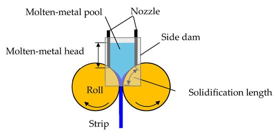
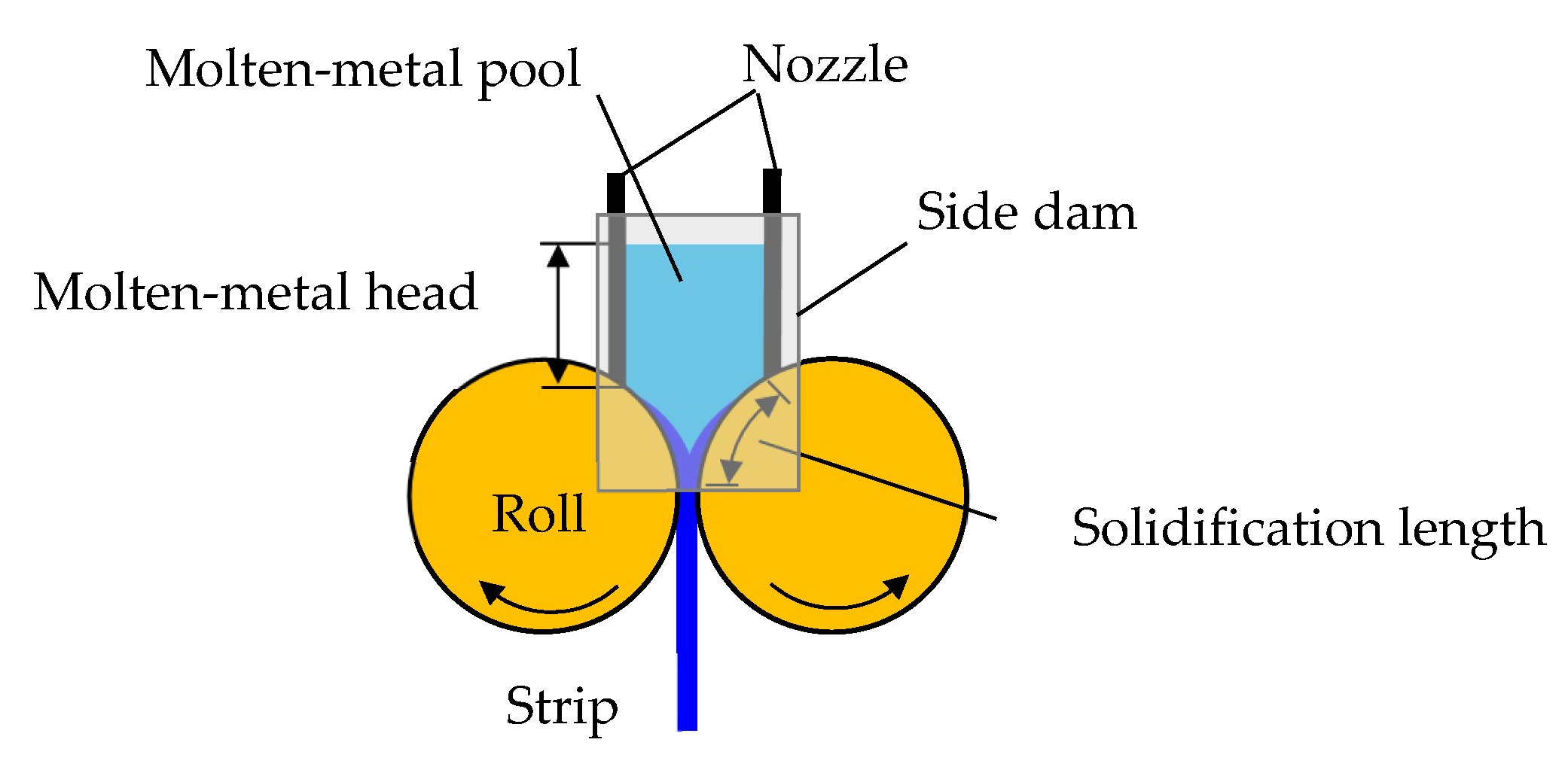
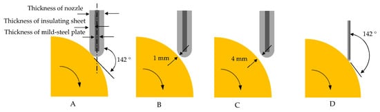
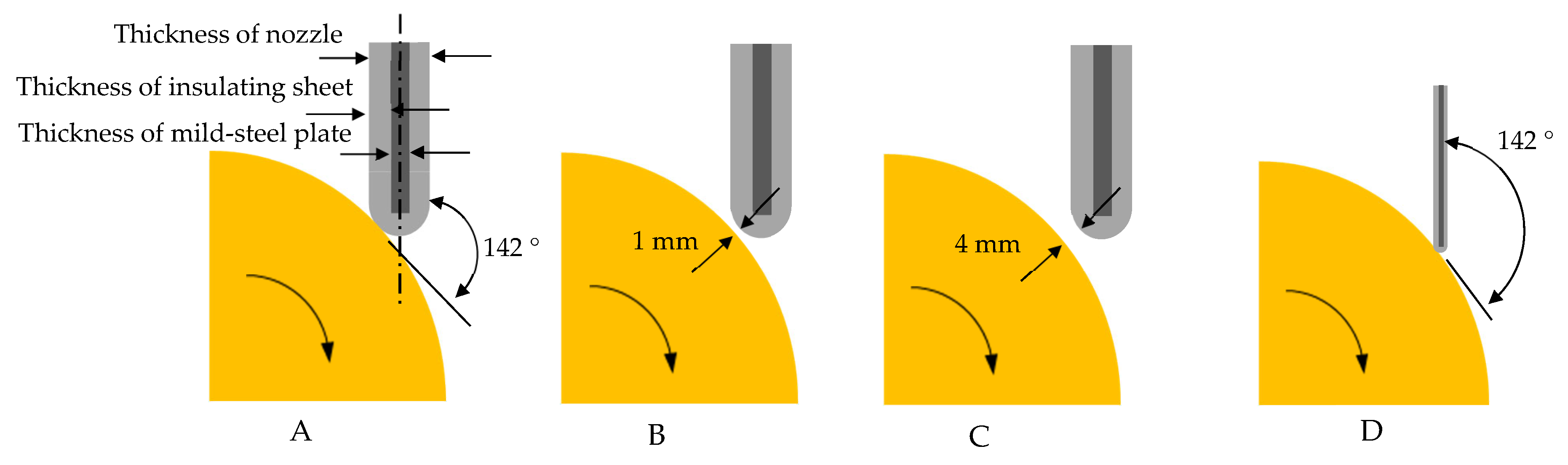
A schematic drawing of the VHSTRC is shown in Figure 1. The VHSTRC was designed and assembled by students in our laboratory at the Osaka Institute of Technology. The rolls were made of pure copper. The roll diameter and width were 300 and 100 mm, respectively. The common experimental conditions were as follows. The roll speed was 60 m/min. The initial roll load before pouring the molten metal was set at 150 N/mm using a coil spring. The roll load was 150 N/mm except when its influence on crack occurrence was being investigated. The initial roll gap was 1 mm. The solidification length was 100 mm. The nozzle was made from a mild-steel plate and an insulating sheet. Four types of nozzle configurations, A, B, C and D, were tested, as shown schematically in Figure 2 and summarized in Table 1. For the Types A-C nozzle configurations, the thicknesses of the nozzle, steel plate, and insulating sheet were 11, 3, and 4 mm, respectively, and the nozzle–roll gaps were 0, 1, and 4 mm, respectively. The Type A nozzle configuration is the basic nozzle–roll gap configuration in a VHSTRC. For the Type D nozzle configuration, the thicknesses of the nozzle, steel plate, and insulating sheet were 3, 1, and 1 mm, respectively, and the nozzle–roll gap was 0 mm. Boron nitride (BN) spray was used on the insulating sheet as a parting material. The composition of the Al-5%Mg alloy used in the present study is shown in Table 2.
Figure 1.
Schematic diagram of vertical-type high-speed twin-roll caster.
Figure 2.
Schematic diagram of nozzle configuration types used in this study. The thicknesses of the mild-steel plate, the insulator sheet and the gap between nozzle and the roll are summarized in Table 1.
Table 1.
Thicknesses of nozzle, mild-steel plate and insulator sheet. Nozzle configuration types are shown in Figure 2.
Table 2.
Chemical composition of Al-5%Mg alloy (mass%).
To investigate the effect of the molten-metal head on the formation of ripple marks, the Type A nozzle configuration was used with molten-metal heads of 50, 100, and 150 mm. The molten-metal head is defined as the distance from the molten-metal surface to the tip of the nozzle, as shown in Figure 1. The molten-metal temperature was 735 °C.
To determine the influence of the molten-metal temperature on ripple mark formation, the Type A nozzle configuration was again used with a molten-metal head of 150 mm, and the pouring temperature of the molten metal was 645, 685, or 735 °C.
When the effect of the nozzle–roll gap on ripple mark formation was investigated, the Types A, B, and C nozzle configurations were used. The molten-metal head was set at 100 mm to prevent leakage of molten metal from the nozzle–roll gap in the Types B and C nozzle configurations. The molten-metal temperature was 735 °C.
When the influence of nozzle thickness on the occurrence of solidified metal and ripple marks was investigated, the Type D nozzle configuration was used. The molten-metal head was 100 mm, and the molten-metal temperature was 735 °C. To investigate the effect of roll load on crack formation, the Type D nozzle configuration was used. The molten-metal head was 100 mm, and the molten-metal temperature was 645 °C. The roll load was 5, 10, 20, or 50 N/mm.
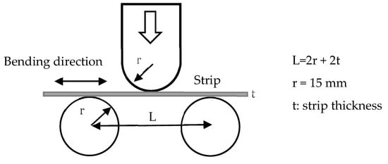
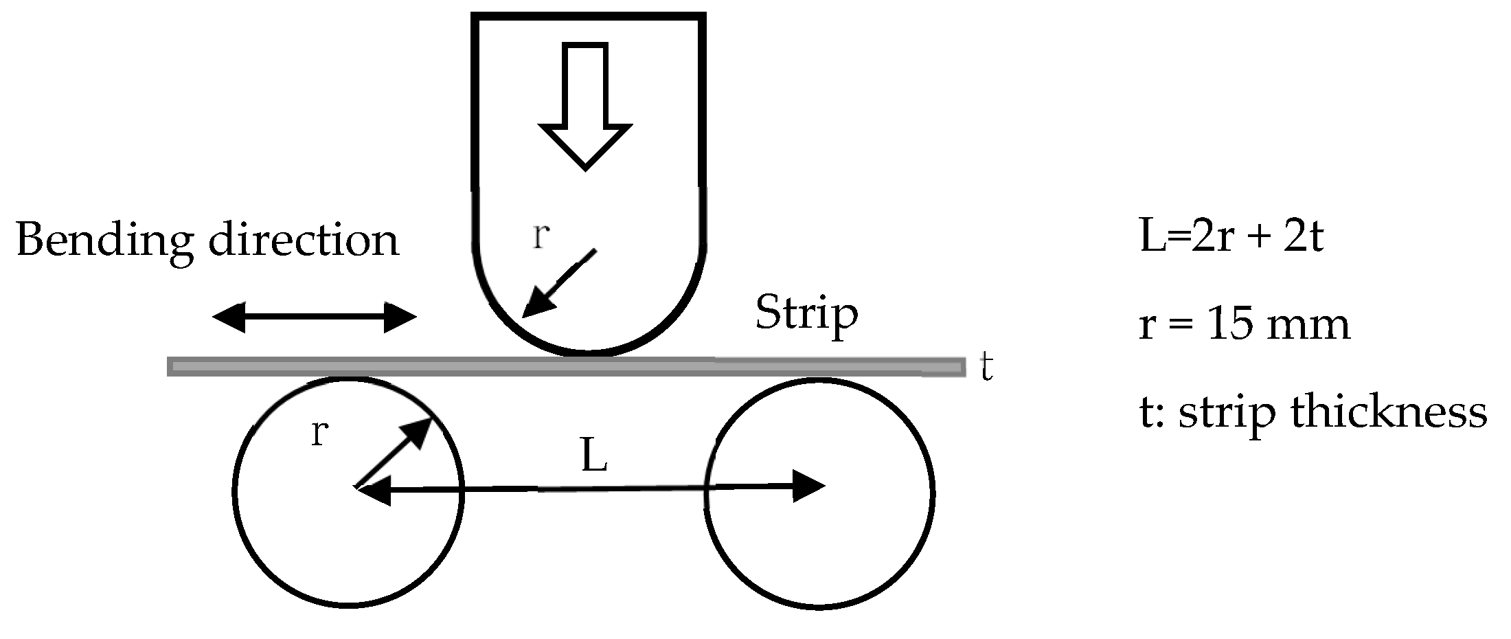
Photographs for visual inspection of the surfaces of the cast strips were taken with a camera (COOLPIX W300, NIKON, Shinagawa, Tokyo, Japan). Penetrant tests and bending tests were carried out to investigate the influence of ripple marks on crack formation and the ductility of the strip surface, respectively. A schematic diagram of the bending test is shown in Figure 3. A universal testing machine (UEH-30, SIMADZU, Nakagyo-ku, Kyoto, Japan) was used for the bending test. The bending directions were the casting direction and the width direction of the strip.
Figure 3.
Schematic diagram of bending test.
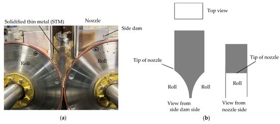
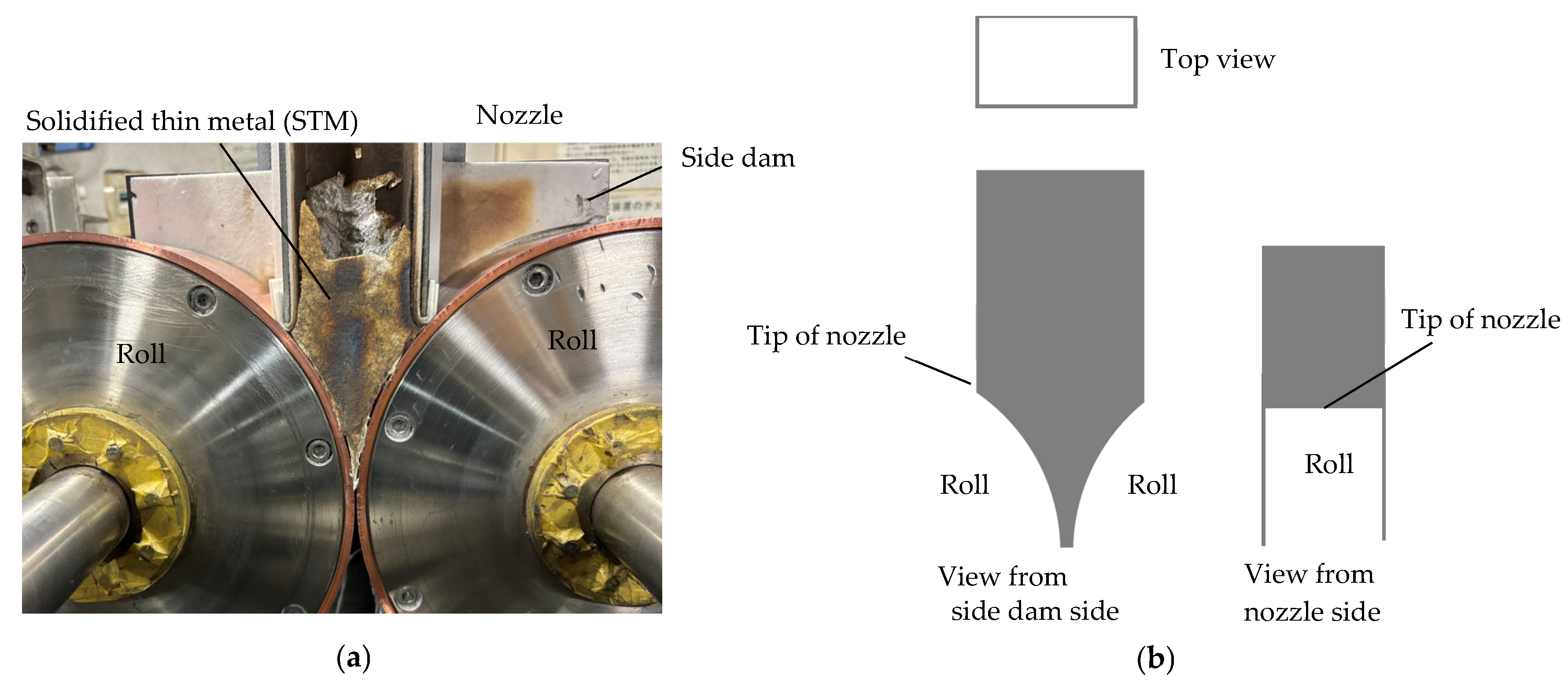
Molten-metal penetration through the nozzle-roll gap was investigated from the solidified thin metal (STM) that had adhered to the insulating sheet after casting, as shown in Figure 4.
Figure 4.
Solidified thin metal (STM) adhered to insulating sheets of nozzle and side dam. (a) STM after casting. Side dam on near side is removed. (b) Schematic diagram of overview of STM.
3. Results
3.1. Effect of Molten-Metal Head on Strip Surface
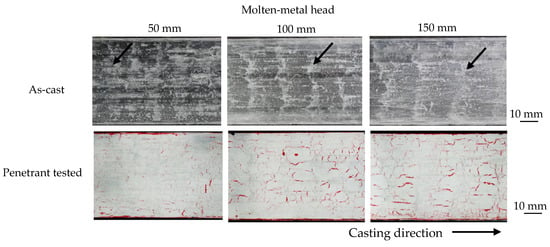
The effect of the molten-metal head on the strip surface is shown in Figure 5. The Type A nozzle configuration was used. The upper panels show the cast strip, and the lower panels show the penetrant-tested surface. The dull areas (areas with poor metallic luster and white areas) are defined as ripple marks in this study and are indicated by black arrows in Figure 5. Ripple marks occurred regardless of the molten-metal head, and they had rough edges and non-uniform lengths in the casting direction. However, the degree of undulation of the ripple marks appeared to increase with increasing molten-metal head, and the interval between the ripple marks also increased with increasing molten-metal head. In the images after penetrant testing, the red regions indicate cracks, which seem to occur in areas other than the ripple marks (white areas). The number of cracks increased with increasing molten-metal head. The reason why cracks occur between the ripple marks is discussed in the Section 4.
Figure 5.
Effect of molten-metal head on strip surface. Upper panels show as-cast strip, and lower panels show penetrant-tested strips. The Type A nozzle configuration was used. The roll speed was 60 m/min. Molten-metal temperature was 735 °C. The roll load was 150 N/mm. The solidification length was 100 mm. In the as-cast strips, black arrows indicate ripple marks. In the penetrant-tested strips, red areas indicate cracks.
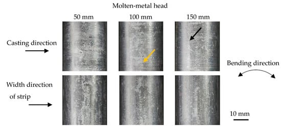
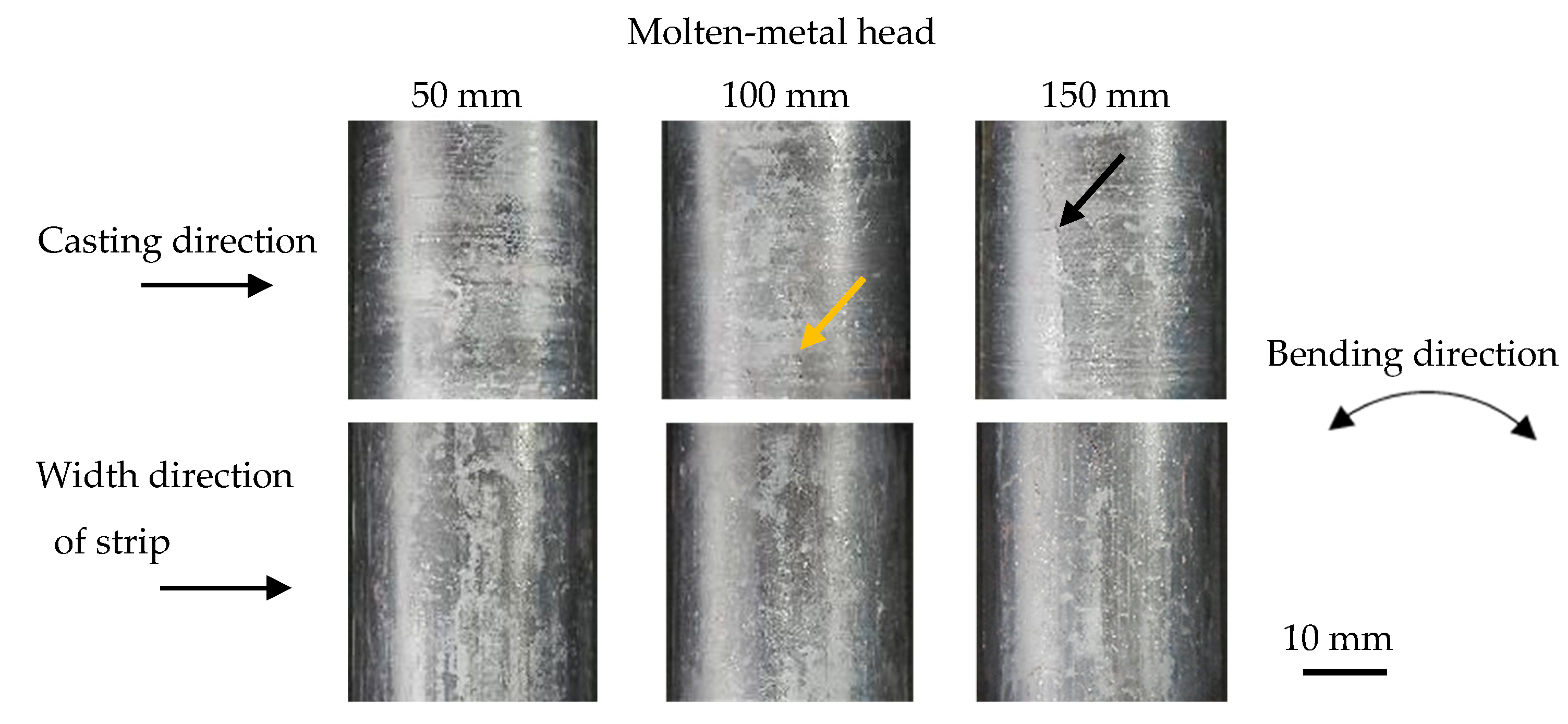
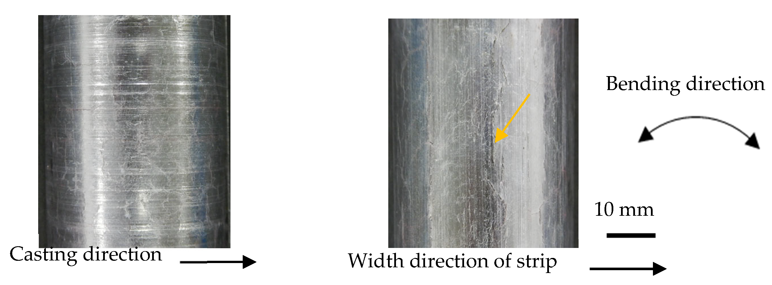
The outer surfaces of the cast strips after the bending test are shown in Figure 6. The cast strips were bent in both the casting direction and the width direction of the strip. When the molten-metal head was 150 mm, and the bending direction was the casting direction, a crack was formed in the width direction, as indicated by the black arrow. Such cracks were found to be very rare for this molten-metal head, with most cracks occurring in the casting direction. This width-direction crack might have originated in a brittle area during bending. Bending did not give rise to casting-direction cracks, and existing casting-direction cracks did not increase in width during the bending test. The relationship between ripple marks and cracks in the width direction is, therefore, not clear.
Figure 6.
Effect of molten-metal head on appearance of outer surface of bent cast strip. The casting conditions are the same as in Figure 4. The black arrow indicates a crack formed by bending. The yellow arrow indicates a crack that already existed on the cast strip.
When the molten-metal head was 100 mm, and the bending direction was the casting direction, an existing width-direction crack opened slightly (shown by the yellow arrow), and no width-direction cracks were formed. When the molten-metal head was 50 mm, and the bending direction was the casting direction, cracks did not occur.
When the bending direction was the width direction, existing casting-direction cracks did not increase in width. It is thought that no new cracks were formed by bending for this molten-metal head.
3.2. Effect of Molten-Metal Temperature on Strip Surface
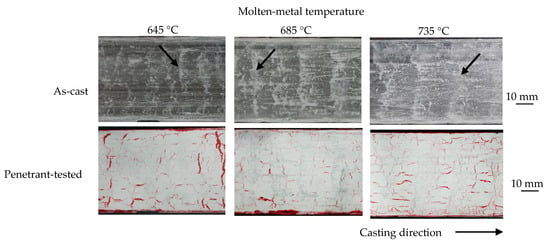
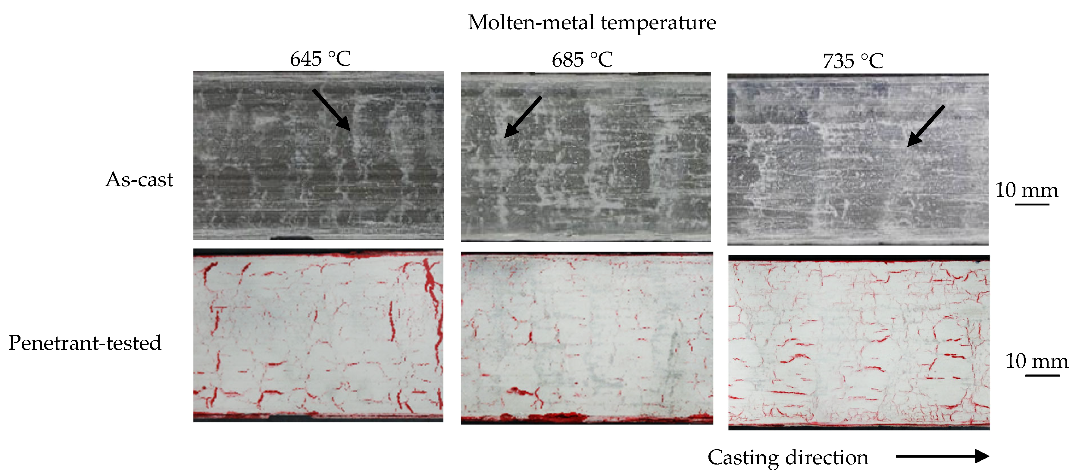
The effect of the molten-metal temperature on the cast strip surface is shown in Figure 7. The Type A nozzle configuration was used with a molten-metal head of 150 mm. Ripple marks became clearer, and the metallic luster between them became more dull as the molten-metal temperature increased. The dull condition may have spread thinly from the dull areas (ripple marks) to the lustrous areas (between ripple marks). In the penetrant test, the molten-metal temperature influenced the direction and size of cracks. When the temperature was 645 °C, the crack direction was the width direction, and the crack size was the largest among the three molten-metal temperatures. When the temperature was 685 °C, the size and number of cracks were the smallest, and few cracks existed in either the casting direction or the width direction. When the temperature was 735 °C, the direction of most cracks was the casting direction. The size of the casting-direction cracks at 735 °C was close to that at 645 °C.
Figure 7.
Effect of molten-metal temperature on appearance of strip surface. Upper panels show cast strips, and lower panels show penetrant-tested strips. The Type A nozzle configuration was used. The roll speed was 60 m/min. The roll load was 150 N/mm. The molten-metal head was 100 mm. The solidification length was 100 mm. In the as-cast strips, black arrows indicate ripple marks. In the penetrant-tested strips, red areas indicate cracks.
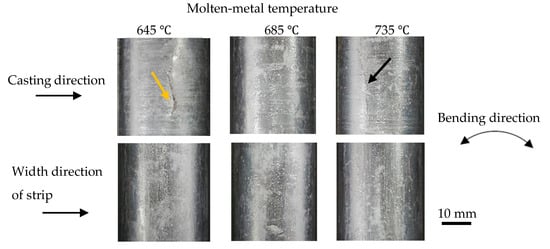
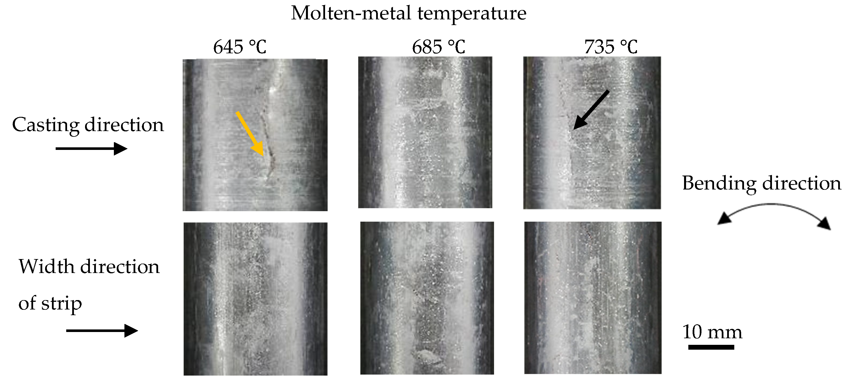
The bending test was conducted on the cast strips shown in Figure 7, and the outer surfaces of the bent strips are shown in Figure 8. When the molten-metal temperature was 645 °C and the bending direction was the casting direction, an existing crack did not increase in open width (shown by the yellow arrow), and no width-direction crack was observed. When the molten-metal temperature was 685 °C, cracks did not occur in either the casting direction or the width direction. The results for a molten-metal temperature of 735 °C in Figure 8 are the same as those for a molten-metal head of 150 mm in Figure 6. Cracks occurred during bending in the casting direction. When the bending direction was the width direction, existing casting-direction cracks did not increase in open width. It is thought that no new cracks were formed during bending. When the molten-metal temperature was 685 °C, few cracks were formed, and the brittle area may have been smaller.
Figure 8.
Effect of molten-metal temperature on appearance of outer surface of bent cast strip. The casting conditions are the same as in Figure 7. The black arrow indicates a crack formed by bending. The yellow arrow indicates a crack that already existed on the cast strip.
3.3. Effect of Nozzle–Roll Gap
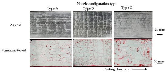
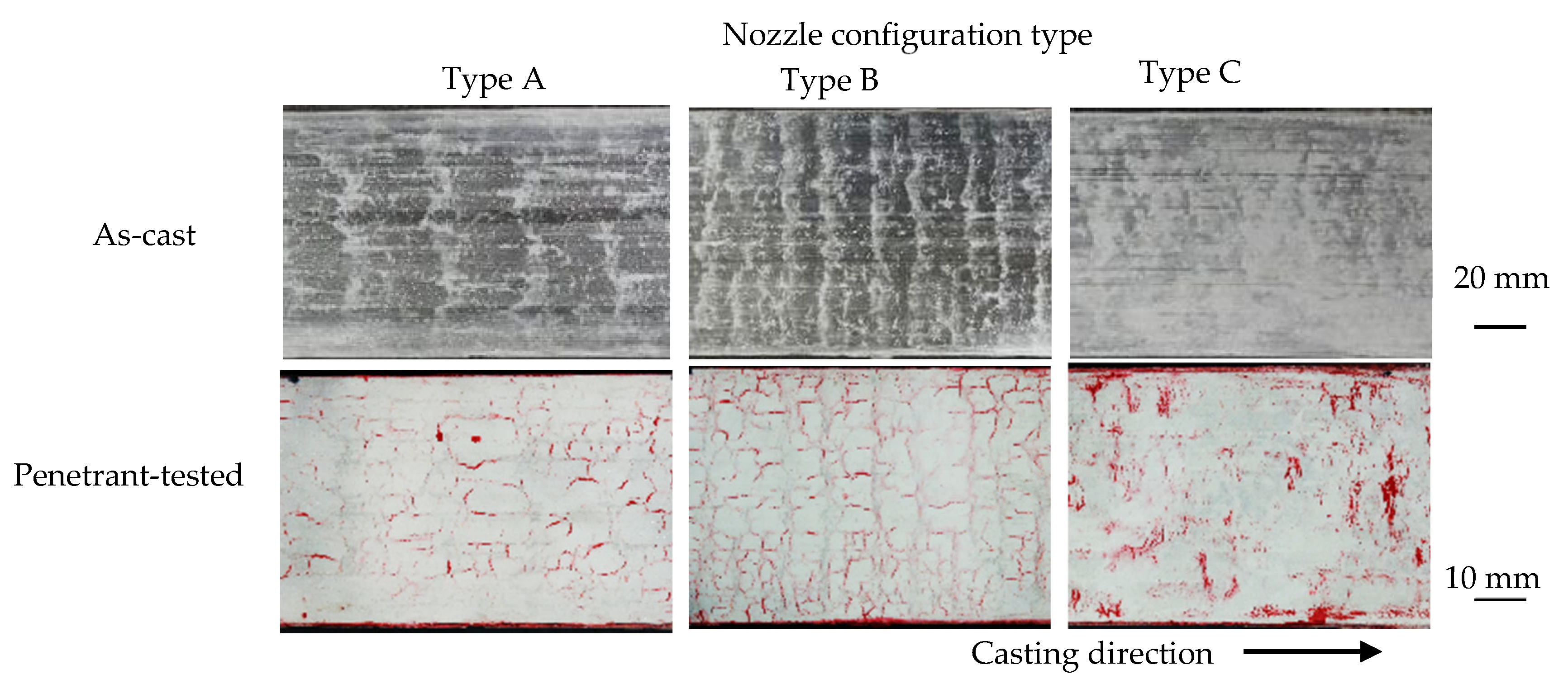
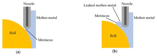
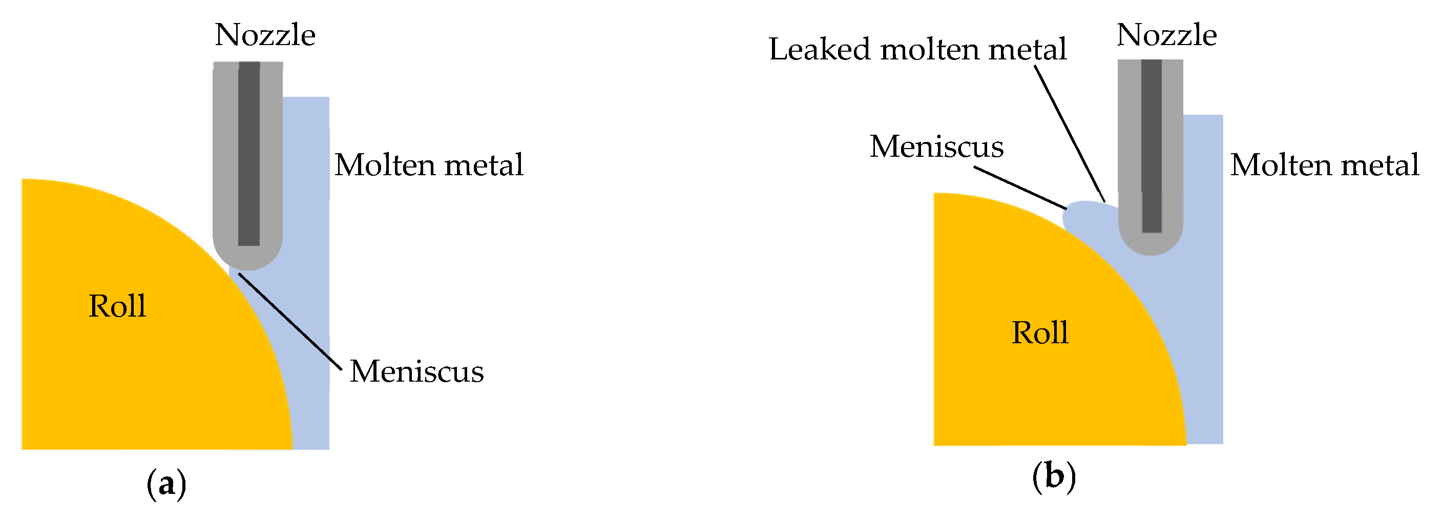
The effect of the nozzle–roll gap on the strip surface was investigated using Types A, B, and C nozzle configurations. The molten-metal temperature was 735 °C, and the molten-metal head was 100 mm. The surfaces of the cast strips are shown in Figure 9. In the Types A, B, and C nozzle configurations, the gaps between the nozzle and the roll were 0, 1, and 4 mm, respectively, and the gap was found to influence the ripple marks. The lustrous area between ripple marks also decreased in the same order. The shape and distribution of the ripple marks for the Type C nozzle configuration were different from those for the Types A and B nozzle configurations. For the Type B nozzle configuration, the molten metal did not leak through the gap between the nozzle and the roll. This condition is schematically shown in Figure 10a. For the Type C nozzle configuration, the molten metal did leak through the gap, as shown in Figure 10b. For the Type C nozzle configuration, the leaked molten metal formed a pool outside the nozzle. The ripple marks might have occurred at the meniscus of the pool, which was not restricted by the nozzle. This might be the reason why the ripple marks for the Type C nozzle configuration were very different from those for the Types A and B nozzle configurations.
Figure 9.
Effect on appearance of surface of cast strip. Upper panels show as-cast strips. Lower panels show penetrant-tested strips. Red areas are cracks. Roll speed was 60 m/min. Molten-metal temperature was 735 °C. Molten-metal head was 100 mm. Roll load was 150 N/mm. Solidification length was 100 mm.
Figure 10.
Schematic diagram showing molten metal near the nozzle. (a) Type B nozzle configuration; (b) Type C nozzle configuration.
For the Type B nozzle configuration, there was a 1 mm gap between the nozzle and the roll, and the molten metal did not leak through the gap. Ripple marks occurred even when the nozzle was not in contact with the roll. One possible cause of ripple-mark formation is oscillation of the meniscus of the molten metal, as described in the Section 4. This can explain the existence of the lustrous areas between ripple marks. This type of ripple mark occurred regardless of whether the nozzle was in contact with the roll. When the Type C nozzle configuration was used, there was a 4 mm gap between the nozzle and the roll, and the molten metal leaked through the gap, producing a pool of molten metal. The dull area was wider than that for the other nozzle configurations. The ripple marks were small in both the width direction and the casting direction. It is considered that the meniscus oscillated and became covered with an oxide film or semisolid layer, producing dull areas.
The results of the penetrant tests are shown in the lower panels in Figure 9. For the Types A and B nozzle configurations, cracks occurred in the lustrous areas, and the crack direction was close to the casting direction. For the Type C nozzle configuration, the size and distribution of the cracks were different from those for the Types A and B nozzle configurations. The reason for this is not clear at present.
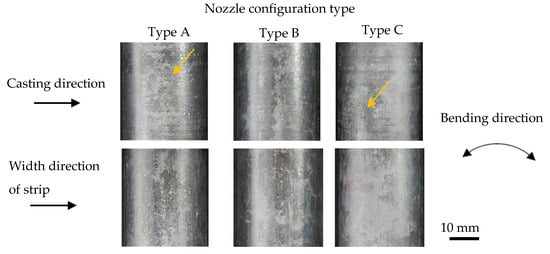
A bending test was conducted on the strips shown in Figure 9, and the results are shown in Figure 11. Cracks did not occur during bending, indicating that the surface condition did not influence crack formation. Yellow arrows indicate cracks that already existed on the cast strip.
Figure 11.
Effect of nozzle type on outer surface of bent cast strip. Yellow arrows indicate cracks that already existed on the cast strip.
3.4. Effect of Nozzle-Thickness
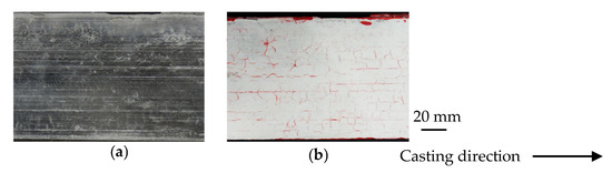
Roll casting was attempted using the Type D nozzle configuration to investigate the influence of nozzle thickness on the ripple marks. The strip-casting conditions were as follows: the molten-metal temperature was 645 °C, the molten-metal head was 100 mm, and the roll load was 150 N/mm. The surface of the cast strip and the penetrant-tested surface are shown in Figure 12. The ripple marks that existed on strips cast using the Types A and B nozzle configurations in Figure 9 did not appear on the strip cast using the Type D nozzle configuration. These results show that the thin nozzle is effective for preventing the occurrence of ripple marks. The results of the penetrant test show that cracks occurred even though ripple marks did not occur. This means that there is no strong correlation between ripple marks and cracks.
Figure 12.
Surface of cast strip using the Type D nozzle configuration shown in Figure 2 and Table 1. (a) is the as-cast strip. (b) is the penetrant-tested strip. Red areas indicate cracks. Molten-metal temperature was 735 °C. Molten-metal head was 100 mm. Roll load was 150 N/mm. Solidification length was 100 mm.
A bending test was conducted on the cast strip shown in Figure 12, and the outer surface of the bent strip is shown in Figure 13. When the bending direction was the casting direction, an existing crack did not increase in width, and no crack occurred during bending. When the bending direction was the width direction of the strip, the width of an existing casting-direction crack increased slightly (shown by the yellow arrow), and no new crack occurred during bending.
Figure 13.
Effect of nozzle type on outer surface of bent cast strip. Cast strip shown in Figure 12a was used. Yellow arrow indicates cracks that already existed on the cast strip.
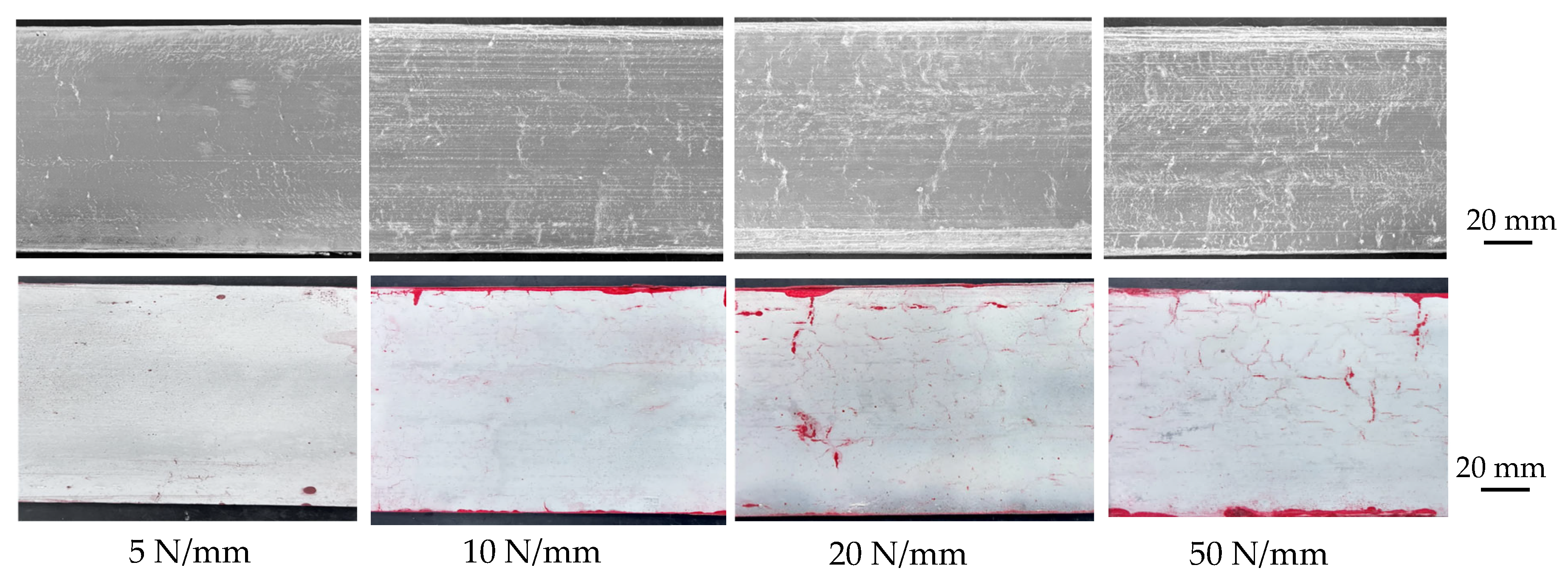
The effect of roll load on the occurrence of cracks was investigated using the Type D nozzle configuration. The molten-metal temperature was 645 °C, the molten-metal head was 100 mm, and the roll load was 5, 10, 20, or 50 N/mm. The surfaces of the cast strips and the results of the penetrant test are shown in Figure 14. Ripple marks did not occur when the roll load was decreased. The amount of cracking decreased as the roll load decreased. When the roll load was 5 N/mm, most of the cracks were eliminated. The roll load is the dominant factor in crack formation. For the Al-5%Mg alloy, a thin nozzle and a small roll load are, therefore, effective for preventing ripple marks and cracks.
Figure 14.
Surface of cast strip (upper panels) and penetrant-tested surface (lower panels). Red areas are cracks. The Type D nozzle configuration was used. Roll loads were 5, 10, 20 and 50 N/mm. Molten-metal head was 100 mm. Molten-metal temperature was 645 °C. Solidification length was 100 mm.
3.5. Solidified Thin Metal Adhered to Insulating Sheets of Nozzle and Side Dam
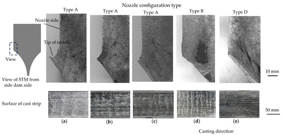
The STM near the nozzle tip (upper panels) and the surfaces of the cast strips (lower panels) for the Types A, B, and D nozzle configurations in Figure 2 are shown in Figure 15, and the casting conditions are summarized in Table 3.
Figure 15.
Solidified thin films (STMs) near nozzle tip (upper panels) and surfaces of cast strips (lower panels). Casting conditions for (a–e) are summarized in Table 3.
In Figure 15a–c, the nozzle configuration is Type A; that in Figure 15d is Type B; and that in Figure 15e is Type D. Molten-metal penetration through the gap between the nozzle and the roll is influenced by the molten-metal head, the molten-metal temperature, and the nozzle position relative to the roll. For the Type A nozzle configuration, the molten metal was expected to penetrate close to the contact position between the nozzle and the roll. In Figure 15a, the molten-metal head was 150 mm, and the molten-metal temperature was 735 °C. In Figure 15b, the molten-metal head was 50 mm, and the molten-metal temperature was 735 °C. The molten-metal head in Figure 15b was lower than that in Figure 15a. In Figure 15c, the molten-metal head was 150 mm, and the molten-metal temperature was 645 °C. The molten-metal temperature in Figure 15c was lower than that in Figure 15a. The molten metal penetrated deeply when both the molten-metal head and molten-metal temperature were high, as shown in Figure 15a. The molten-metal penetration in Figure 15b,c was shallower than that in Figure 15a. This means that both the molten-metal head and molten-metal temperature influence the penetration of molten metal between the nozzle and the roll. When the molten-metal head is higher, the pressure of the molten metal at the tip of the nozzle becomes higher, and the molten metal penetrates deeply. When the molten-metal temperature is higher, the flow distance before solidification becomes longer, and the molten metal penetrates deeper. In Figure 15d, the nozzle configuration was Type B, there was a 1 mm gap between the nozzle and the roll, and it appeared that the molten metal did not penetrate this gap. Alternatively, the molten metal penetrated and a small pool formed, but the pool temperature did not decrease before the STM was formed on the surface of the insulating sheet of the nozzle. In Figure 15e, the nozzle configuration was Type D, the molten-metal head was 100 mm, and the molten-metal temperature was 645 °C. The molten metal penetrated only very shallowly because of the thin nozzle, as the curvature at the tip of the nozzle was small.
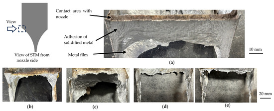
Observations from the roll side of the STM near the tip of the nozzle under the conditions in Table 3 are shown in Figure 16. The labels (a-e) in Figure 16 correspond to those in Figure 15. In Figure 16a, adhesion of solidified metal to the tip of the nozzle (ASMTN) occurred. In Figure 16b,c, small amounts of ASMTN were observed. No ASMTN was observed in Figure 16d,e. Comparing the results in Figure 15 with those in Figure 16, it is estimated that the ASMTN became larger as molten-metal penetration between the nozzle and the roll became larger.
Figure 16.
Adhesion of STM at nozzle tip. Nozzle configuration types: (a–c) Type A, (d) Type B, and (e) Type D. Casting conditions for (a–e) are summarized in Table 3.
4. Discussion
4.1. Molten-Metal Penetration Through the Nozzle–Roll Gap and Ripple Marks
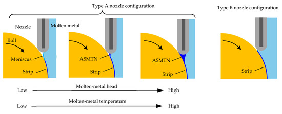
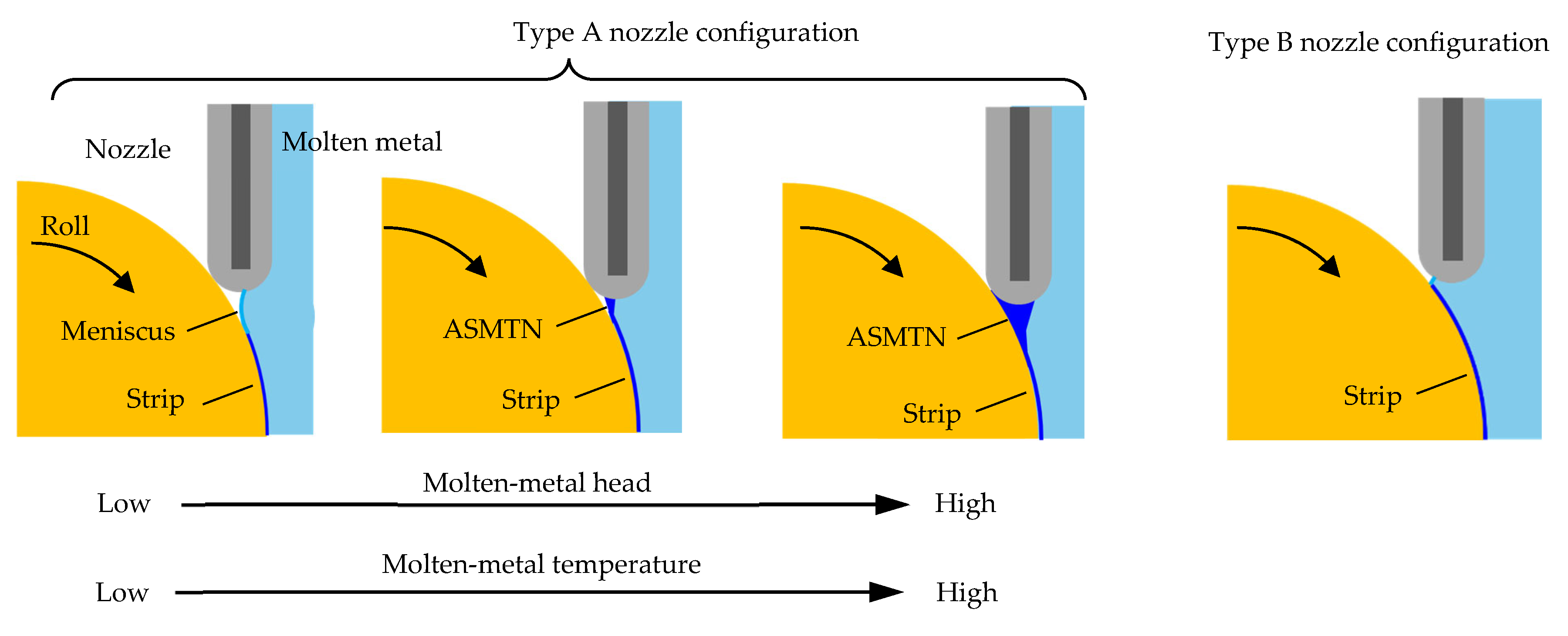
Based on Figure 15 and Figure 16, the influence of the molten-metal head, molten-metal temperature, and nozzle configuration on molten-metal penetration is schematically illustrated in Figure 17. Molten-metal penetration increases as the molten-metal head and molten-metal temperature increase. As molten metal penetrates more deeply, the gap between the nozzle and the roll decreases, making solidification of the molten metal and growth of the ASMTN easier.
Figure 17.
Schematic diagram showing effects of the molten-metal head and the molten-metal temperature on adhesion of solidified metal at the tip of the nozzle tip.
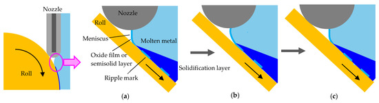
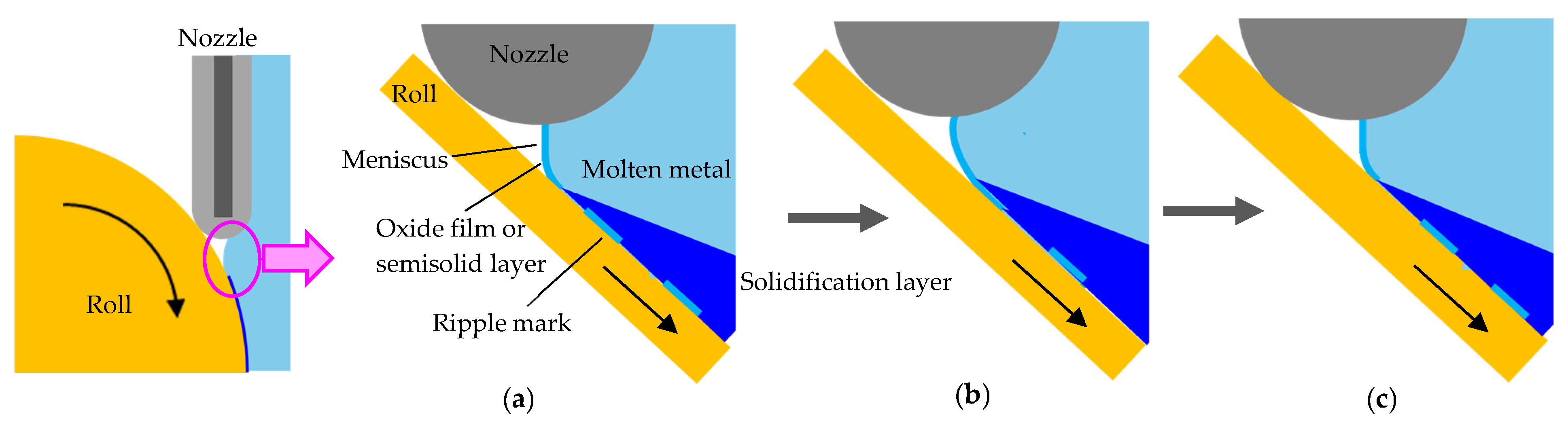
In Figure 15 and Figure 16, the area between the ripple marks becomes dull as molten-metal penetration and the amount of ASMTN increase. The ASMTN may be the cause of the dullness between ripple marks. Based on Figure 16a,e, the occurrence of ripple marks does not appear to be determined only by the existence of solidified metal. The ripple marks undulate as the molten-metal head and molten-metal temperature increase, as shown in Figure 5 and Figure 8, and the edge of the ASMTN also undulates as the molten-metal head and molten-metal temperature increase, as shown in Figure 16a. This shows that there is a correlation between the undulations of the ripple marks and the tip of the ASMTN. It is considered that the ripple marks may occur at the tip of the ASMTN. When no solidified metal exists, ripple marks are likely formed by oscillation of the meniscus, as shown in Figure 18. The oscillation of the meniscus may be constant in the width direction at the tip of the nozzle, and the ripple marks, therefore, do not undulate. In Figure 18, an oxide film or semisolid layer is seen to form at the outer surface of the meniscus. As the meniscus becomes elongated from Figure 18a to b, the oxide film or semisolid layer is dragged under the molten metal by the rotating roll, and the molten metal solidifies on the oxide film or semisolid layer. The elongated meniscus is broken or detached from the tip of the nozzle, and the molten metal directly contacts the roll, as shown in Figure 18c. The oxide film or semisolid layer becomes the ripple mark, which appears as a dull area. The area where the molten metal contacts the roll becomes the lustrous area. This process is repeated, and ripple marks occur.
Figure 18.
Schematic diagram showing occurrence of ripple marks when meniscus forms between the nozzle and the roll. Oscillation of the meniscus and dragging of the broken oxide film or semisolid layer proceed in (a–c).
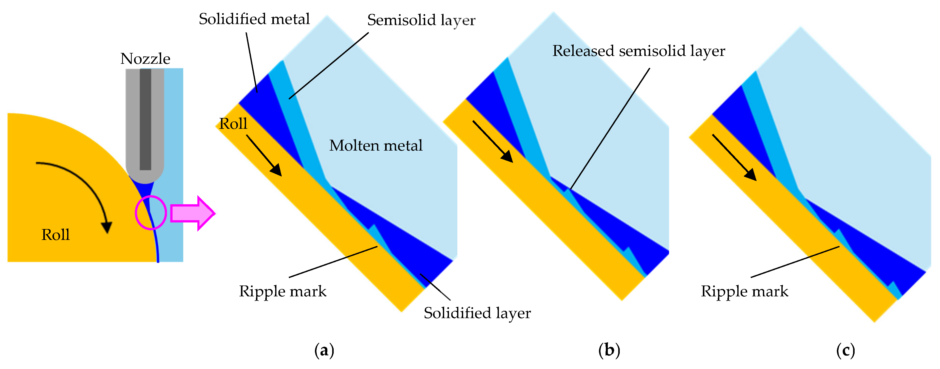
Figure 19 shows an illustration of the possible ripple mark formation mechanism when ASMTN occurs, causing the strip surface to become dull. A semisolid layer exists on the ASMTN, as shown in Figure 19. The thin semisolid layer is dragged between the roll and the molten metal, as shown in Figure 19a. The tip of the semisolid metal is broken, as shown in Figure 19b. The thickness of the back part of the broken semisolid metal is slightly larger than that of the thin semisolid layer in front of it. The broken semisolid metal becomes the ripple mark, as shown in Figure 19c. This process is repeated, and ripple marks are formed.
Figure 19.
Schematic diagram showing occurrence of ripple marks when solidified metal adheres to nozzle tip. Dragging of the broken semisolid layer proceeds in (a–c).
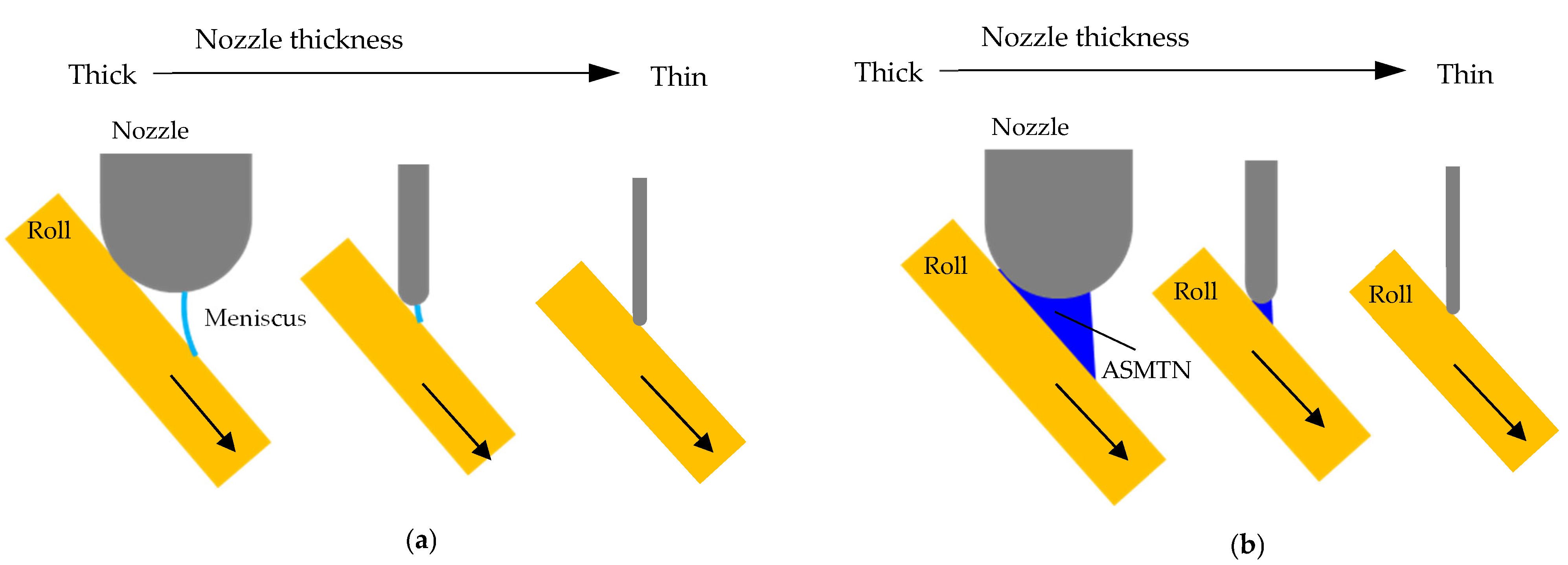
The predicted influence of the nozzle thickness on the formation of the meniscus and ASMTN is shown in Figure 20. The size of the meniscus and the amount of ASMTN decrease as the nozzle thickness decreases, because the area between the tip of the nozzle and the roll becomes smaller as the nozzle becomes thinner. When the nozzle thickness is less than 3 mm, the meniscus and ASMTN that influence the occurrence of ripple marks may not exist.
Figure 20.
Schematic diagram of prediction of influence of nozzle thickness on formation of meniscus and AMSTN. (a) Meniscus; (b) ASMTN.
4.2. Ripple Marks and Surface Cracks
When ripple marks occurred, cracks were formed in the lustrous areas, as shown in Figure 5, Figure 7 and Figure 9. Heat transfer between the solidified layer and the roll in the lustrous areas may be greater than that in the dull areas because the semisolid film in the dull areas may provide heat resistance between the molten metal and the roll. There was no difference in thickness between the lustrous areas and the dull areas because the thickness became uniform due to the roll load. However, the solidified layer in the lustrous areas is thicker than that in the dull areas, and the forming load in the dull areas may be smaller than that in the lustrous areas at the roll bite. Cracking may, therefore, be suppressed by using a smaller roll load. This is consistent with the result shown in Figure 14, which shows that cracking decreased as the roll load decreased.
5. Conclusions
This study clarified the casting conditions suitable for eliminating ripple marks in the strip casting of Al-5%Mg using a vertical-type high-speed twin-roll caster. Al-5%Mg was used because it is very susceptible to ripple mark formation. Al-5%Mg was cast at 60 m/min.
The formation of ripple marks was influenced by the molten-metal head, molten-metal temperature, and gap between the nozzle and the roll. These casting conditions did not directly affect ripple mark occurrence; rather, they affected the morphology of the ripple marks. The thickness of the nozzle affected the occurrence of ripple marks. When the thickness of the nozzle was reduced from 11 mm to 3 mm, the ripple marks were eliminated.
When the nozzle tip was in contact with the roll, penetration of the molten metal into the gap between the nozzle and the roll increased as the molten-metal head and molten-metal temperature increased. The amount of solidified metal adhered to the tip of the nozzle increased as the penetration of molten metal into the gap between the nozzle and the roll increased. The solidified metal adhered to the tip of the nozzle affected the occurrence and morphology of the ripple marks. When the nozzle thickness was 3 mm, adhesion of solidified metal to the tip of the nozzle did not occur; as a result, ripple marks did not occur.
When there was a gap between the nozzle tip and the roll, solidified metal did not adhere to the tip of the nozzle, but ripple marks occurred.
No correlation was found between ripple marks and cracks. The roll load affected the occurrence of cracks. The cracks decreased as the roll load decreased. Most of the cracks were eliminated when the roll load was reduced from 150 N/mm to 5 N/mm.
In the roll casting of Al-5%Mg at 60 m/min, a nozzle thickness of 3 mm and a roll load of 5 N/mm were, therefore, found to be suitable for casting strips without ripple marks or cracks.
Author Contributions
Conceptualization, T.H.; methodology, T.H. and T.Y.; validation, T.H.; formal analysis, T.H. and T.Y.; investigation, T.H. and T.Y.; resources, T.H.; data curation, T.H. and T.Y.; writing—original draft preparation, T.H. and T.Y.; writing—review and editing, T.H.; visualization, T.H.; supervision, T.H.; project administration, T.H.; funding acquisition, T.H. All authors have read and agreed to the published version of the manuscript.
Funding
This research was supported by Suzuki Foundation (https://www.suzukifound.jp/, accessed on 15 June 2024).
Institutional Review Board Statement
Not applicable.
Data Availability Statement
The original contributions presented in this study are included in this article; further inquiries can be directed to the corresponding author.
Conflicts of Interest
The authors declare no conflicts of interest.
References
- Hamer, S.; Romanowski, C.; Taraglio, B. Continuous casting and rolling of aluminum: Analysis of capacities, product ranges, and technology. Light Met. Age 2002, 60, 6–17. [Google Scholar]
- Ertan, S.; Dundar, M.; Birol, Y.; Sarioglu, K.; Ozden, E.; Akkurt, A.S.; Yildizbayrak, G.; Hammer, S.; Romanowski, C. The effect of casting parameters on twin roll cast strip microstructure. Light Met. 2000, 2000, 667–672. [Google Scholar]
- Thomas, P.M.; Grocock, P.G.; Bouzendorffer, L.M. Dynamic strip caster—An update on the operation of the roll caster at Eurofoil. Metall. Plant Technol. Int. 1997, 21, 44–52. [Google Scholar]
- Nussbaum, A.I. Three state-of- the art thin gauge high-speed roll caster for aluminum sheet product part III. Light Met. Age 1997, 55, 34–39. [Google Scholar]
- Yun, M.; Lokyer, S.; Hunt, J.D. Twin roll casting of a aluminium alloys. Mater. Sci. Eng. A 2000, 280, 116–123. [Google Scholar] [CrossRef] [Scilit]
- Haga, T.; Kurahashi, Y. Effect of Roll Material on Strip Solidification between the Rolls of a Vertical-Type High-Speed Twin-Roll Caster. Metals 2022, 12, 1699. [Google Scholar] [CrossRef] [Scilit]
- Haga, T. High Speed roll caster for aluminum alloy. Metals 2021, 11, 520. [Google Scholar] [CrossRef] [Scilit]
- Dantzig, J.; Meydanoğlu, O.; Kazazi, A.; Altuner, H.I.M.; Işıksaçan, C.I.; Şerefoğlu, M.I. Microstructure and crystallographic texture in twin-roll casting of AA1050 aluminum alloy: Simulation and industrial validation. Metall. Mater. Trans. A 2022, 53, 4168–4187. [Google Scholar] [CrossRef] [Scilit]
- Liu, Z.; Wang, Y.; Chen, Q.; Meng, L.; Yang, Z.; Tang, H.; Qian, X.; Xu, Y.; Li, Y.; Li, X. The Typical microstructure of twin-roll cast 2139 alloy and its impact on mechanical properties. Crystals 2026, 16, 13. [Google Scholar] [CrossRef] [Scilit]
- Dündar, K.; Altuncu, E.; Birbaşa, O. Deep drawability of Al-Mg alloys produced by twin roll continuous casting method: Investigation of microstructure and mechanical properties. Metals 2024, 14, 1365. [Google Scholar] [CrossRef] [Scilit]
- Jin, J.W.; Zhang, Z.J.; Li, R.H.; Li, Y.; Gong, B.S.; Hou, J.P.; Wang, H.W.; Zhou, X.H.; Purcek, G.; Zhang, Z.F. Mechanical properties of three typical aluminum alloy strips prepared by twin-roll casting. J. Mater. Res. Technol. 2024, 28, 500–511. [Google Scholar] [CrossRef] [Scilit]
- Qian, A.; Xu, Z.; Song, B.; Ma, Y.; Jia, P. Effect of pulse electric current on macro-segregation during twin-roll casting of Al-Mg-Si alloys. Mater. Trans. 2025, 66, 878–887. [Google Scholar] [CrossRef] [Scilit]
- Kim, M.S.; Kim, J. Metallurgical method of determining heat transfer coefficient in simulations of twin-roll casting. Metals 2024, 14, 358. [Google Scholar] [CrossRef] [Scilit]
- Uiimann, M.; Stirl, M.; Prahl, U. Twin-roll casting defects in light metals. J. Mater. Sci. 2024, 59, 19003–19022. [Google Scholar] [CrossRef] [Scilit]
- Özel, F.; Başaran, A.; Belit, S.; İpek, S.K.; Demir, B. Investigation of ripple formation in aluminum flat products produced by different types of twin roll casters. Light Met. 2024, 2024, 273–277. [Google Scholar] [CrossRef] [Scilit]
- Frischknecht, B.; Maiwald, K.P. Roll caster applications and development. Light Met. 1988, 1988, 365–372. [Google Scholar]
- Cortes, M.; Pechiney-JUMBO 3CM. The new demands of thin strip casting. Light Met. 1995, 1995, 1161–1164. [Google Scholar]
- Esaki, H.; Watanabe, Y.; Ueda, K.; Uto, H.; Shibue, K. Effect of casting conditions on ripple mark of twin-roll cast Al-Mg-Si alloy strip. J. Jpn. Inst. Light Met. 2006, 56, 266–270. [Google Scholar]
- Taga, T.; Takahashi, K.; Ikawa, M.; Watari, H. A vertical type Twin roll caster for aluminum alloy strips. J. Mater. Process. Technol. 2003, 140, 610–615. [Google Scholar] [CrossRef] [Scilit]
- Haga, T.; Nishiyama, T.; Suzuki, S. Strip casting of A5182 alloy using a melt drag twin-roll caster. J. Mater. Process. Technol. 2003, 113, 103–107. [Google Scholar] [CrossRef] [Scilit]

Disclaimer/Publisher’s Note: The statements, opinions and data contained in all publications are solely those of the individual author(s) and contributor(s) and not of MDPI and/or the editor(s). MDPI and/or the editor(s) disclaim responsibility for any injury to people or property resulting from any ideas, methods, instructions or products referred to in the content. |
© 2026 by the authors. Licensee MDPI, Basel, Switzerland. This article is an open access article distributed under the terms and conditions of the Creative Commons Attribution (CC BY) license.