Review

Heat-Assisted Metal Spinning: Review
Mechanical Engineering Department, École de Technologie Supérieure, 1100 Notre-Dame St W, Montreal, QC H3C 1K3, Canada
*
Author to whom correspondence should be addressed.
Metals 2026, 16(5), 483; https://doi.org/10.3390/met16050483
Submission received: 16 March 2026 / Revised: 21 April 2026 / Accepted: 23 April 2026 / Published: 29 April 2026
(This article belongs to the Special Issue Advanced Metallic Materials and Forming Technologies)

Abstract

Heat-assisted metal spinning comprises incremental forming routes, conventional spinning, shear spinning and flow forming, performed at elevated temperature to increase formability. This review consolidates the main advances of the last fifteen years. It outlines spinning mechanics and the rationale for heating (higher ductility, lower forming forces and microstructure control), then compares global and local heating strategies (furnace, flame, induction, laser and hot-gas convection) in terms of temperature uniformity, industrial practicality, energy efficiency and cost. Key process parameters (spindle speed, feed rate and thickness reduction) are discussed with respect to defect formation, and representative windows for defect mitigation are reported. Progress in modeling is reviewed, including coupled thermo-mechanical finite element simulations, damage/formability prediction and emerging data-driven optimization. The review also summarizes microstructural evolution under heat-assisted conditions, phase transformation, dynamic recrystallisation and grain growth, and its impact on final properties. Across more than 100 studies, evidence shows that robust thermal management can roughly double achievable deformation before failure and enables property tailoring in difficult-to-form alloys (Ni-based alloys, high-strength steels, Al, Mg and Ti). Remaining challenges include reliable in situ temperature measurement/control and improved predictive fidelity of simulations. Future opportunities include digital twins, real-time sensing and adaptive, machine-learning-assisted control.

1. Introduction

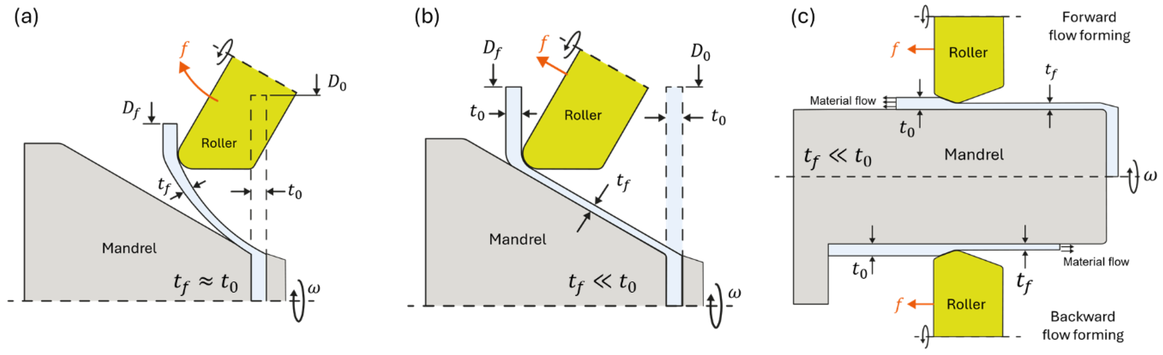
Metal spinning is a group of chip-less incremental forming processes used to produce thin-walled components. Over the last 60 years, different classifications have been proposed for metal spinning technology depending on the mechanics, deformation characteristics, internal stresses, tool configuration, and temperature [1,2,3]. However, they have been grouped into three main processes (see Figure 1): conventional spinning, shear spinning, and flow forming [4]. The common characteristic of these processes is that they make it possible to produce thin-walled hollow components from a rotating metallic blank or tube by applying localized plastic deformation through the continuous feed of one or more rollers.
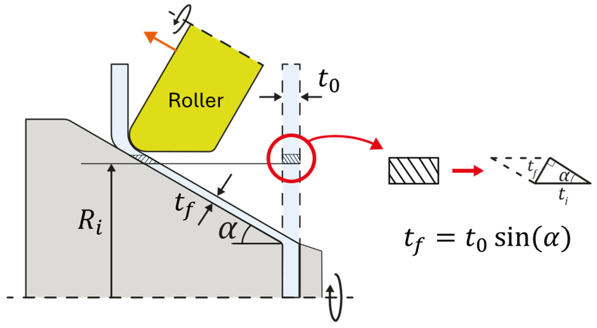
As illustrated in Figure 1, apart from the geometry of the starting material, these processes differ primarily in their approach to thickness reduction. In conventional spinning, the total deformation is given in multiple passes, where the final shape is ideally obtained by progressively reducing the diameter while keeping the thickness unchanged. In practice, a certain thinning does occur, and the first roller pass has a significant influence on the final thickness [5]. By contrast, shear spinning imposes a prescribed thickness reduction based on the mandrel wall angle ( α ) and roller’s trajectory, where each radial position of an element in the blank remains at the same radial position ( R i ) (see Figure 2) [6]. The so-called sine law, t f = t i sin ( α ) , defines the equilibrium condition that ensures simple shear as the dominant deformation mechanism [7]. Minor deviations from the sine law are permissible but can induce unwanted defects such as cracks or wrinkles.
In flow forming, the inner diameter of a cylindrical tube is ideally maintained, and the roller-imposed thickness reduction causes the elongation of the tube. Two different configurations exist: backward flow forming, where the material flows in the opposite direction to the roller; and forward flow forming, where the material flows in the same direction to the roller’s movement (see Figure 1c). Although flow forming and shear spinning share a compression–shear deformation mechanism, they differ in the shape of the starting blank: tube for flow forming versus disk for shear spinning. In addition, in flow forming, the thickness reduction is usually given by three axially distributed rollers, where each roller gives a certain degree of deformation, and the final thickness reduction is imposed in different passes and does not follow any direct relationship with the other process parameters. In practice, aspects of these three processes can be combined in a single manufacturing route to produce components with complex geometries. For instance, a part with both conical and cylindrical sections may require shear spinning for the cone and flow forming for the cylinder, or a steep cone may be initially shaped by shear spinning and finished by multi-pass conventional spinning when the mandrel angle becomes too shallow for single-pass forming. In such combined routes, the thickness reduction strategy must be coordinated across stages to ensure dimensional compatibility. The most suitable approach depends on the final geometry, the required thickness distribution, and the formability of the material at the selected forming temperature.

1.1. Historical Background

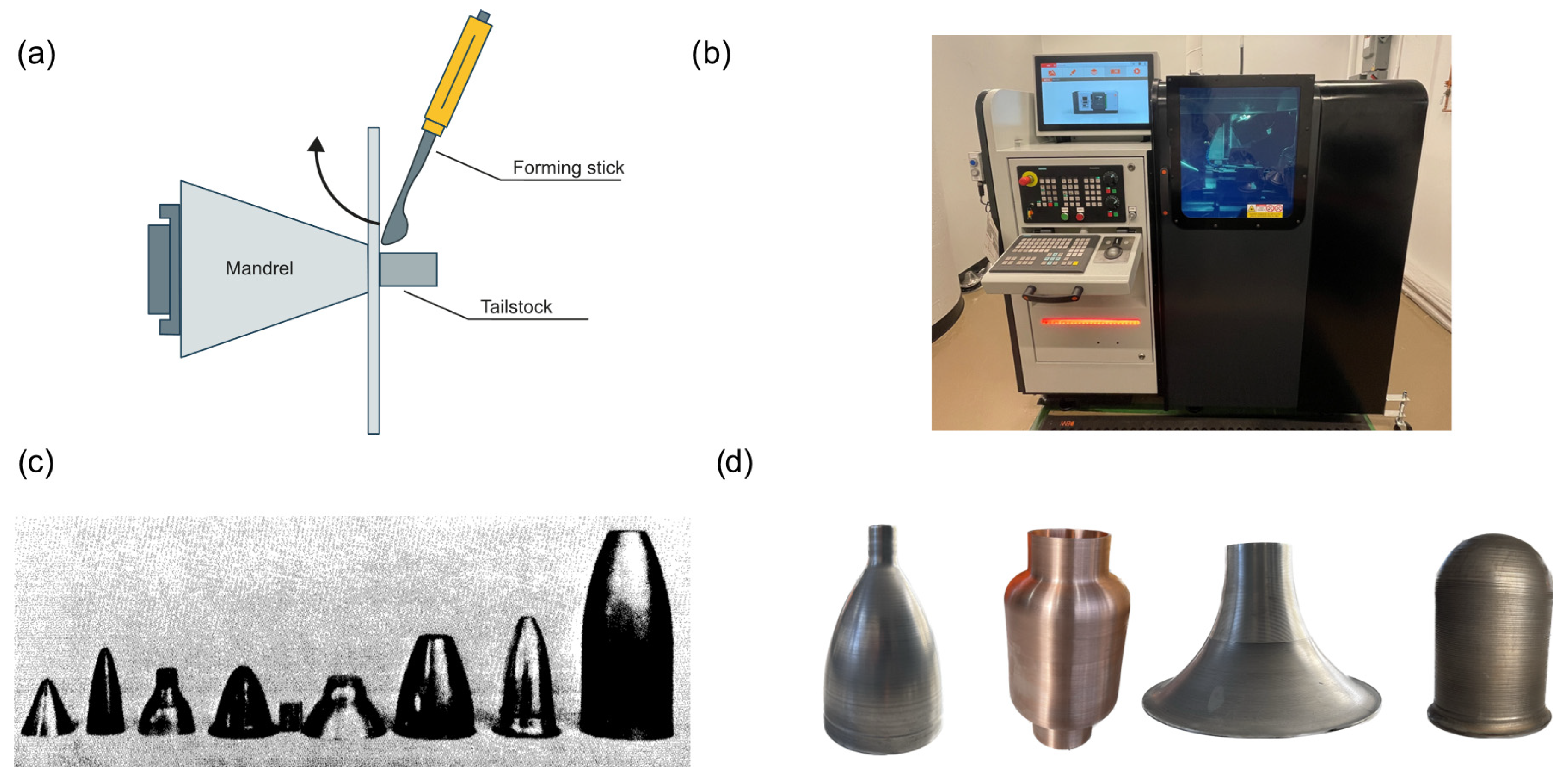
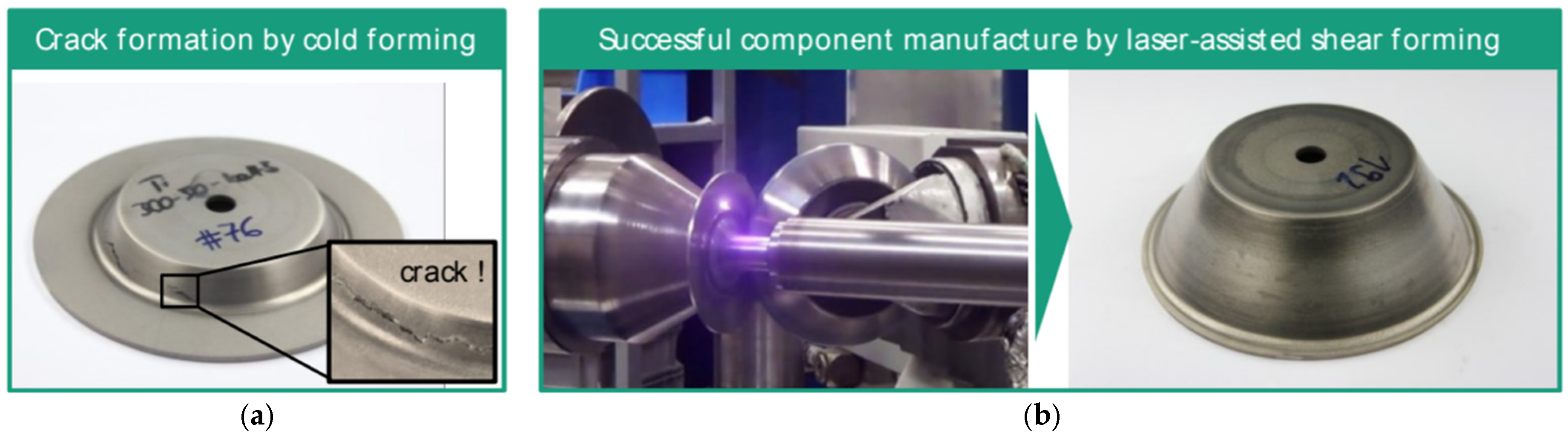
Traditionally, at the industrial scale, metal spinning was manually performed and used for relatively simple, axisymmetric shapes in products like kitchenware and lighting (Figure 3a,c). Today it is still actively employed for artisanal, restoration, and other low-volume work. However, a transition to power-driven methods in the early 1970s supported by automated control systems and computer numerical control (CNC) integration (Figure 3b) significantly expanded process capabilities and throughput [2]. This shift enabled higher production volumes, reduced labor requirements, and the manufacturing of complex geometries using higher-strength materials (Figure 3d). Consequently, metal spinning began to serve demanding applications in aerospace, automotive, and defense sectors, where lightweight, high-strength, and geometrically complex components are highly sought.
Research in metal spinning has continued to evolve, moving the focus from descriptive analysis to understanding the mechanics of the process [10], and then to diagnostic analyses for process optimization, material behavior, and forming limits [11,12]. In this sense, key areas of advancement in the early 2000s have included the development of more robust numerical simulations, the refinement of CNC with adaptive control technologies, and the integration of real-time monitoring to improve quality and reduce defects.
Regarding heat-assisted spinning, the earliest records date back to 1907 in a U.S. patent describing a purpose-built heating device for spinning lathes that keeps the blank at forming temperature during spinning [13]. Mid-century industrial practice documents flame-assisted tube end spinning for high-pressure cylinders [14]. By the 1990s, coordinated power spinning with movable heaters under computer control was described by Hoffmann and Staskelunas [15]. Academic records of heat-assisted spinning appear by the late 1990s when Han and Chen [16] analyzed temperature-gradient effects in spun cylinders. Early 2000s conference reports by Klocke and Wehrmeister [17] introduced laser-assisted spinning for difficult-to-form alloys. Shortly after, Murata et al. [18] quantified the forming limits in magnesium alloys, subsequent works extended the approach to titanium shells [19] and to coupled thermo-mechanical modeling of hot spinning [20]. Further, Mori [21] provided an influential early study on cast aluminum that helped consolidate mechanisms, defect control, and process windows. In the last 15 years increasing emphasis has been placed on predictive analysis, incorporating advanced modeling that accurately predicts microstructure evolution [22], defect formation [23], and real-time process sensing to achieve higher geometric precision, quality and mechanical properties to meet modern engineering demands [24].

1.2. Importance of Studying Heat-Assisted Metal Spinning

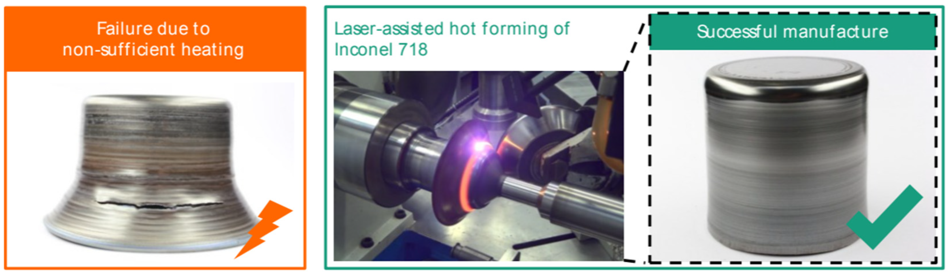
One of the most relevant advantages of metal spinning processes is the localized compressive stress state developed during the process, which enhances the formability beyond the traditional forming limits [25,26]. As a result, components with challenging geometries or made of high-strength alloys can often be spun where traditional methods (e.g., deep drawing or ironing) might fail [2,27]. Nevertheless, certain high-performance alloys such as titanium, nickel or magnesium alloys, which exhibit high strength and hardening rates or require elevated temperature to achieve sufficient ductility, often demand heat assistance during spinning (Figure 4) [28,29]. At elevated temperatures (>0.5–0.6 Tm), the effect of strain hardening decreases, and strain rate effects become important, making heat-assisted spinning an increasingly critical area of research for next-generation high-performance parts [30,31].
As interest in space exploration, aerospace, aeronautics, defense, and automotive applications continues to grow, heat-assisted spinning emerges as a strong candidate for manufacturing high-performance, lightweight, thin-walled structures [27,32]. The ability to form Ni-based superalloys, high-strength steels, titanium, magnesium, and aluminum at low forces provides significant advantages in terms of mechanical performance and production efficiency when compared with other traditional sheet metal forming processes [33]. Shape memory alloys (SMAs), and NiTi-based systems, represent another potential target family given their close relationship to Ti- and Ni-based alloys. However, the spinning of SMAs remains largely unexplored, with only a few simulation-based studies on backward ball spinning of NiTi tubes at elevated temperature reported [34,35]. Heat-assisted spinning of SMAs could offer a promising route to manufacture thin-walled components for biomedical and aerospace applications but dedicated experimental and numerical studies are still needed. Accordingly, hot spinning is receiving renewed attention in both academic and industrial research for the manufacturing of components such as rocket nozzles and other critical biomedical, aerospace and automotive parts [26,31,36].

1.3. Temperature-Based Classification in Hot Spinning

As in any other metal forming processes, temperature-based classification includes hot, warm, and cold forming. Hot forming often refers to temperatures above the recrystallization point, roughly above half of the melting point (>0.5–0.6 Tm), whereas warm forming is typically performed between room temperature and the recrystallization temperature [37]. Cold forming generally takes place near room temperature. For difficult-to-deform materials like Ni-based superalloys, and titanium and magnesium alloys, higher deformation temperatures must be used to ensure adequate formability and no less important, to reduce the forming forces and residual stresses [31]. However, at elevated temperatures, microstructural changes driven by dynamic recovery (DRV) and dynamic recrystallization (DRX) could take place and significantly impact the final properties of the spun components [22].
Given these advancements and emerging challenges, this review focuses on the potential of heat-assisted spinning as a promising approach in modern metal forming. A sequence of nine comprehensive reviews published between 1982 and 2020 follows the evolution of metal spinning. The earliest, by Kalpakjian and Rajagopal [38], studied tube-spinning mechanics, while Wong et al. [2] provided the first comparative study of conventional, shear and flow forming. Subsequent contributions deepened specific themes: materials and tooling [39], mechanics [3], tube flow-forming technology [40], process variable optimization [41], predictive models for CNC machines [42], industrial integration [43] and spinnability assessment [44]. However, all of them focus on cold spinning, and only two additional reviews concentrate on heat-assisted spinning routes: [31] covers advances in hot spinning of lightweight alloys, highlighting heating strategies, spinnability at elevated temperatures, thermal boundary conditions for finite element analysis (FEA) and future research avenues; and Xia et al. [45] organized hot power spinning studies by heating source and linked common macroscopic defects (e.g., surface bulging, cracking, peeling, and pile-up) with process parameters and microstructural evolution in difficult-to-deform metals. Yet, to date, a comprehensive assessment that thoroughly combines the different facets of heat-assisted metal spinning has not been carried out. The aim of this review paper is thus to discuss the most significant research in the last 15 years and identify existing knowledge gaps in heat-assisted metal spinning processes, and finally, provide insights into future perspectives for the field, including modeling, process optimization, and potential applications in high-performance industries.

2. Heating Sources and Temperature Control

Precise heating and good temperature control are essential for successful hot spinning, as they significantly influence formability, surface quality, microstructural evolution, oxidation, forming forces, and final mechanical properties. Because incremental forming processes, such as metal spinning, concentrate the deformation in a small contact zone, local rather than global heating is preferred. The core challenge, therefore, is to supply adequate thermal energy to this narrow deformation zone while avoiding large temperature gradients that could distort the workpiece or lead to defects. Over the last two decades, various global and local heating methods have been explored, including furnace preheating, flame heating, induction heating, laser heating, hot-gas convection, and heated tooling [31,46]. In this section, the latest advancements in terms of temperature uniformity, process efficiency, equipment complexity, cost, and quality of the final spun part from each of the previously mentioned heating methods are discussed.

2.1. Furnace Preheating

Furnace preheating is a time-tested approach for any hot forming process at large scale, including hot spinning. Preheating in a separate furnace is often used to bring not only the blank, but also the tools up to the desired temperature prior to the forming operation [47,48]. This strategy may result in a homogeneous temperature at the beginning, but as soon as the blank is exposed to ambient temperature or the spinning operation commences and the cold tools contact the blank, the temperature quickly drops [31]. Such drops can lead to low quality or defects in the final part and must be counteracted with an active heat source, e.g., flame torches, induction coils, or laser, to chase uniformity throughout the process [49,50].

2.2. Flame-Assisted Heating

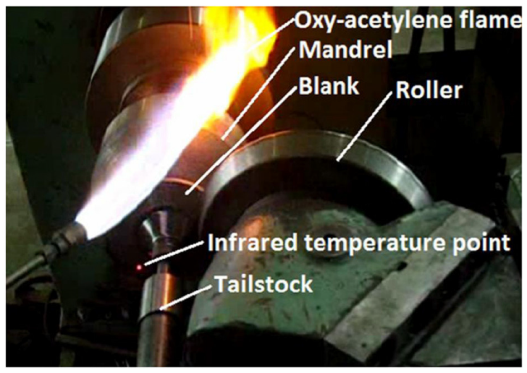
Flame heating with gas torches remains one of the most common methods due to its relative simplicity and cost-effectiveness (Figure 5). Several studies have demonstrated successful spinning using burners with different gases, such as oxyacetylene, acetylene or propane. However, it often led to significant temperature gradients [31].
Yoshihara et al. [52] heated AZ31 magnesium alloy tubes to 300 °C with a hand-held burner during neck-spinning. A non-contact temperature sensor helped maintain consistent forming conditions; nevertheless, a temperature gradient of ±20 °C remained, which was still small enough to preserve ductility and allowed the tube to be spun closed without defects. Likewise, Su et al. [53] and Li et al. [51] used flame-assisted heating for Ti75 and AZ31 magnesium alloys, respectively, each achieving substantial thickness reductions, up to 80% in the case of titanium and 50% for the magnesium alloys.
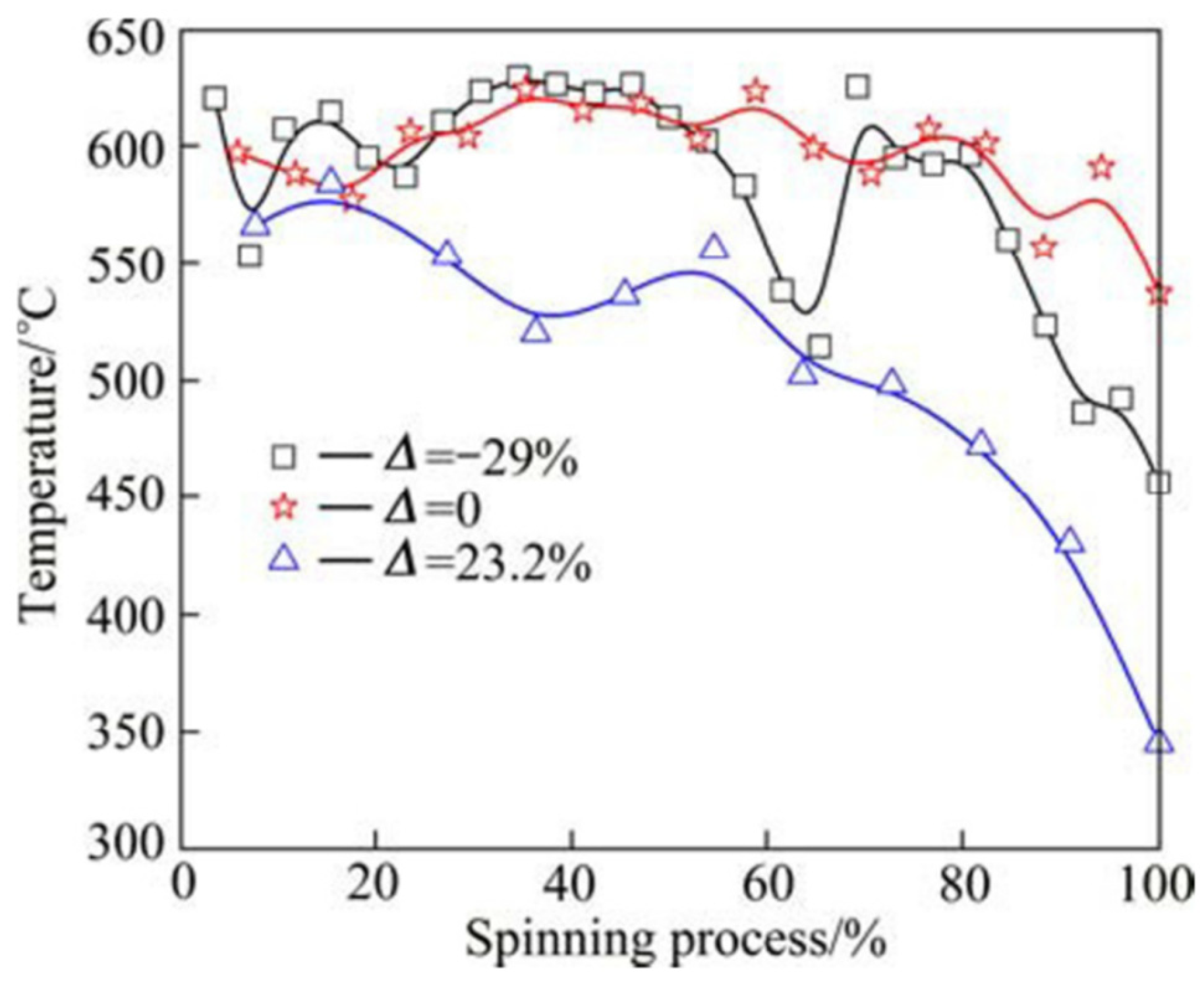
Zhan et al. [54] heated TA15 titanium alloy to 500–600 °C with two hand-held torches and monitored the temperature with an infrared thermometer during hot shear spinning. They observed severe temperature fluctuations because the heat balance is inherently uneven (see Figure 6); the outer surface gains heat from the flame while losing it at the same time through radiation and natural convection, whereas the inner surface, which alternately touches the mandrel or open air, loses most of its heat by conduction into the tooling. This asymmetric, time-varying heat flow may produce geometric inaccuracies, a strain gradient along the thickness, residual stresses, cracks or wrapped geometries [31]. Additionally, local overheating may alter grain growth or promote oxidation, making it unsuitable for certain sensitive materials [55].
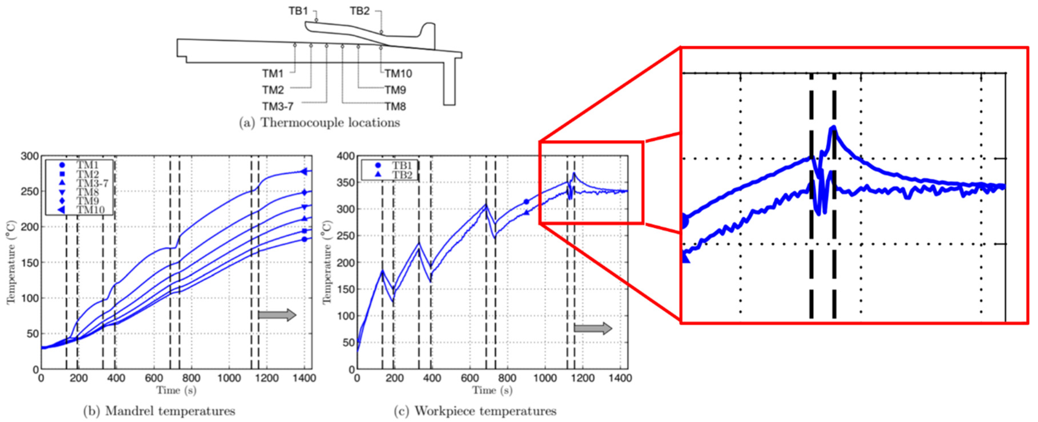
Roy and Maijer [56] formed A356 aluminum wheel rims at 355 °C using a bank of propane torches. Before forming, the steel mandrel was brought to 150 °C with the same torches and coated with graphite, while the blank was preheated in a separate furnace to the same temperature, then lubricated, allowed to cool, and then mounted. Once clamped, the blank was reheated in situ to the target forming temperature of 355 ± 8 °C in 17–23 min. During reheating, the temperature was monitored by several K-type thermocouples, ten embedded in the mandrel (TM1–TM10) and two on the outer surface of the blank (TB1 and TB2) (see Figure 7). During steady heating at 20 rpm, the temperature rise across the blank was remarkably uniform, with the temperature difference betweenTB1–TB2 never exceeding 20 °C, andTB2 remaining consistently cooler. When the spindle speed was increased to the forming spindle speed of 281 rpm, the temperature at TB2 fell rapidly in an almost exponential way until it converged with the nearly steady TB1 reading, thereby eliminating the axial temperature gradient.
Although propane flame heating was effective, Roy and Maijer [56] noted large global temperature variations (about 50 °C in 15 s) when the clamps had to be adjusted in the middle of the process (indicated by dashed bands in Figure 7) demonstrating that even short lapses in heating produce large thermal gradients. In addition, their study revealed that the high convective cooling that accompanies high spindle speeds must be countered with sufficient heat input.
One aspect rarely discussed in the reviewed studies is the systematic optimization of torch-related variables, such as heating power, burner count, and positioning. In most studies, flame assistance is tuned empirically, which highlights a clear opportunity to develop more structured guidelines and best practices that treat heating as a controllable subsystem. In practice this means preheating the mandrel to limit heat losses, arranging burners so they envelop the forming zone and follow it, and instrumenting the process with real-time temperature measurements to detect and correct cold spots.

2.3. Hot-Gas Convection Heating

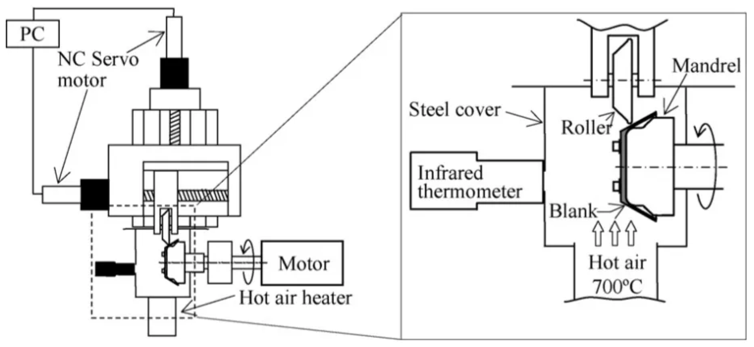
Mori et al. [21] proposed an innovative heating system through hot-air convection as a means to reach a more uniform temperature prior to and during spinning. They used a convection closed system with hot air to prevent rapid cooling or large fluctuations in temperature during the process (see Figure 8). The set point of the chamber was 700 °C, and the spinning operation was carried out when the part reached 400 °C, and since the forming operation was as short as 1 min, the temperature fluctuation was only about ±5 °C. During the process the temperature was measured by an infrared thermometer. This configuration allowed them to successfully spin a cast aluminum alloy, resulting in substantial elimination of microstructural defects and cracks. Hot-air solutions can perform well, but they need a large enclosed chamber and heat-resistant spinning hardware. Each time the chamber is opened to extract a workpiece, the temperature drops, and the next cycle demands longer reheating. The net effect is low productivity and efficiency [31]. All these considerations might complicate the implementation on an industrial scale and increase the cost of production.

2.4. Induction Heating

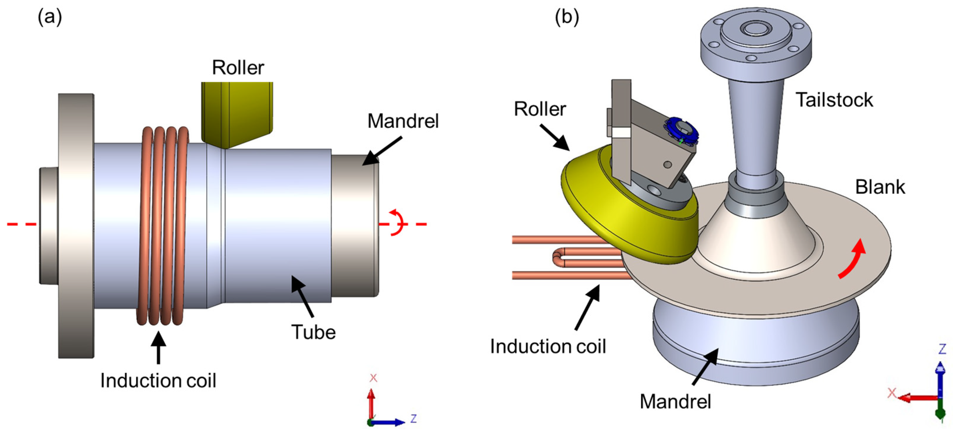
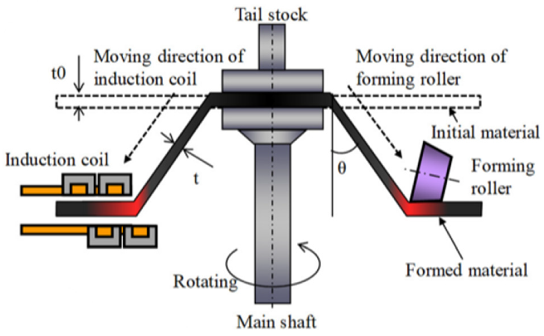
Electromagnetic induction offers a highly efficient, localized, and controllable heating source, making it a popular solution for hot spinning, especially in flow forming where the coil can directly follow the roller in the axial direction (Figure 9a) [57]. In the case of spinning a flat coil can be placed between the mandrel and the flange of the blank, following the roller movement while heating the material just before deformation. The latter configuration has been reported only for mandrel-free spinning [58], but some adaptation for conventional or shear spinning with a mandrel may be possible (Figure 9b). However, this last case has not been tested yet and some trials must be carried out to verify its feasibility.
Some of the advantages of the induction heating systems are that they can quickly reach the target temperature, with a narrow accuracy as low as ±5 °C [59], while the main drawbacks are that they necessitate specialized equipment (e.g., coils, power supply, and cooling), which can reduce practicality and increase costs [46].
Han et al. [60] used an induction coil for preheating AA3003 aluminum disks to different temperatures in the range between 120 and 320 °C with the objective of avoiding crack formation. The results showed that in the range of 200–280 °C successful parts were obtained. The temperature was kept as low as possible to avoid excessive heating, oxidation, grain coarsening and material accumulation that could lead to cracks. Although the results were promising, the authors do not report real-time temperature measurements during spinning. The temperature drop may therefore be similar to that observed with flame heating, so the real processing temperature must be lower. Similarly, Huang et al. [61] used a high frequency induction system to preheat JIS G3141 steel tubes to 1000 °C, that were processed by neck-spinning in a second stage without heating. They report that heating allowed them to form in four passes the spun part successfully. However, no details were provided about the homogeneity and fluctuations of the temperature during the process.
In other studies, Long et al. [22] and Yuan et al. [57] emphasized the benefit of localized induction to improve the control of the DRX that takes place during flow forming in the contact zone. Induction heating methods were similarly studied by Xiao et al. [62] and Xia et al. [63] for high-temperature spinning of Ni-based superalloys and magnesium alloys, respectively. Those studies showed promising results in terms of microstructural evolution due to the precise control that induction heating offers.
Imamura et al. [58] developed a mandrel-free hot-spinning setup for titanium thick plates that uses induction heating as the primary heat source, with the coil mechanically synchronized to the roller, so the deformation zone stays hot while the tool advances (see Figure 10). The temperature was set to 950 °C and monitored by a pyrometer with closed-loop feedback to the power supply, which is a strong point compared with studies that run open-loop. Heating was applied from both sides of the workpiece in the contact region to reduce through-thickness gradients. This configuration allowed stable hot spinning while limiting flange distortion. The authors reported that the combination of the synchronized coil and feedback control presented a practical route to uniform, repeatable thermal conditions for thick specimen spinning.
Lastly, although induction heating has shown strong results for tubular geometries, only one study applying it to disk-shaped blanks using mandrel-free shear spinning was found. In that configuration the coil cannot directly heat the tool–material contact region, so the heated track is synchronized with, but slightly offset from, the deformation zone (Figure 9b). However, the benefits of the coil-tracking concept for mandrel-supported disk spinning need to be assessed before application. Even for difficult-to-form alloys, induction remains an attractive option, combining precise, closed-loop temperature control with a potentially lower cost than laser-based heating.

2.5. Laser Heating

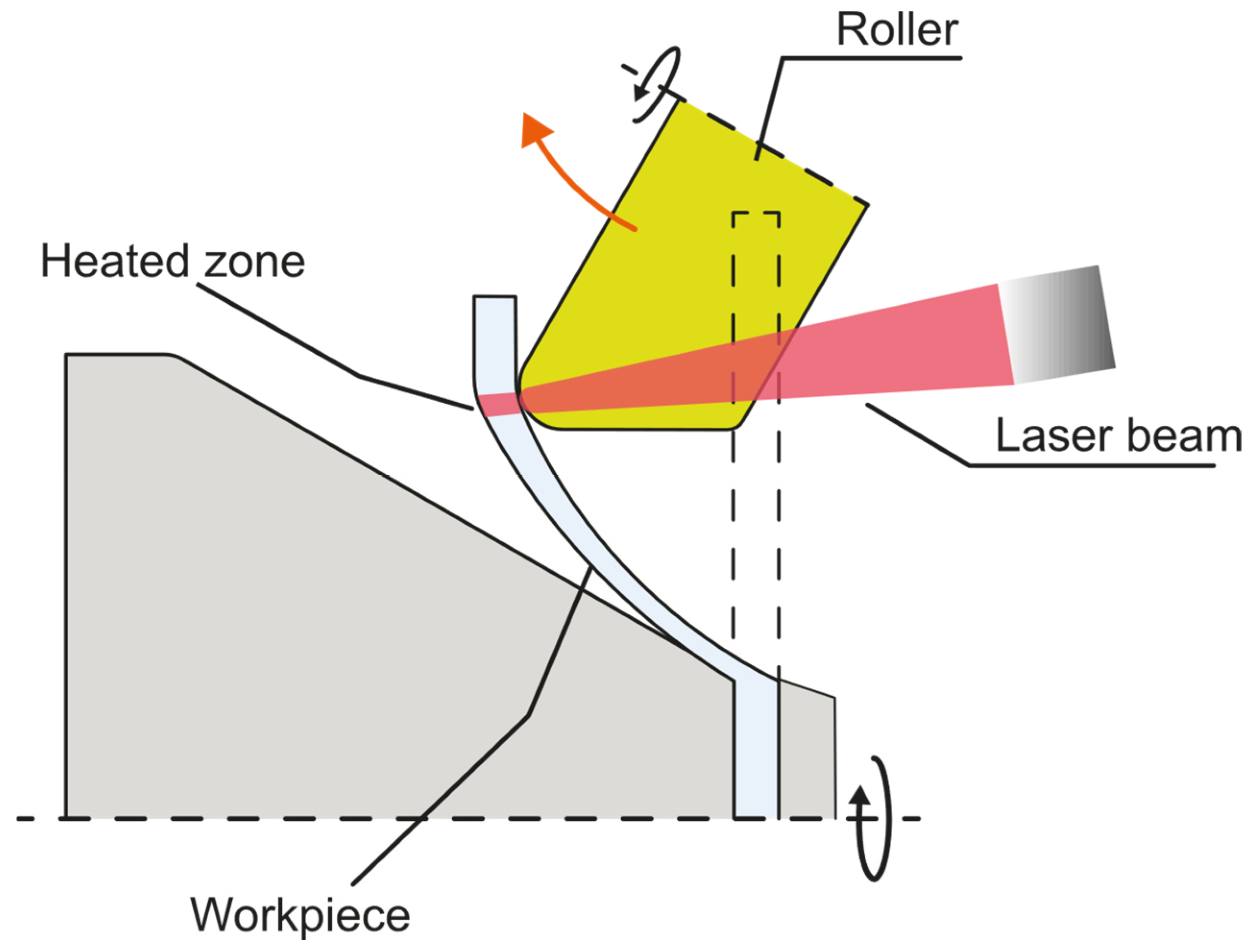
Laser heating has been growing in popularity as a heating solution, due to the capability of concentrating high heating power in a localized controllable spot. Given the localized nature of this heating source, the implementation in traditional bulk forming processes is not reasonable; however, the incremental nature of the metal spinning process where the deformation is highly localized makes it a promising heating method. Therefore, this approach fulfills the requirements needed to spin challenging alloys that require high forming temperatures (e.g., Ni-based superalloys, Ti alloys and high-strength steels), plus improving the components’ quality due to temporally and locally limited heating [29]. Despite these clear advantages, maintaining synchronization between the heating spot and the forming zone during the spinning operation can be challenging, especially for parts with complex geometries.
Laser systems can address the limitations of flame and induction heating, particularly when forming titanium or Ni-based alloys at high temperatures, since heat is applied exactly where and when needed (see Figure 11), so it can reduce the risk of tool overheating and overall part distortion [17,29,64].
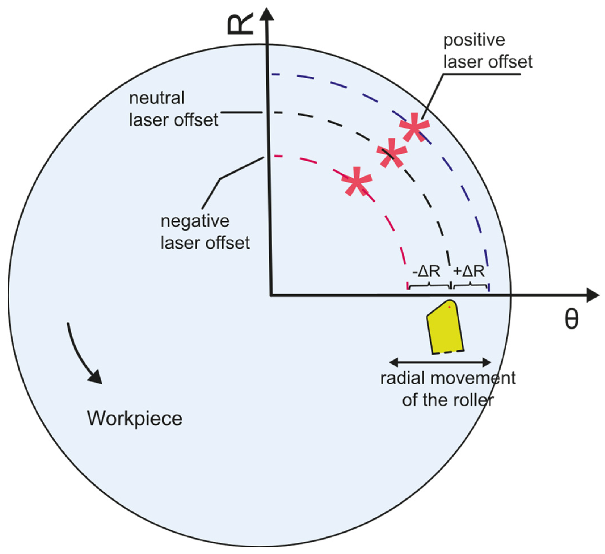
The earliest report using laser-assisted spinning was done by Klocke and Wehrmeister [17]. They demonstrated the potential of this approach by increasing the formability of X5CrNi18-10 stainless steel by25% while reducing the forming force by 40%. A subsequent study by Klocke and Brummer [65] brought to light that laser heating offers reproducible thermal inputs and potentially could eliminate multiple intermediate annealing steps typically done in cold spinning. Furthermore, they analyzed three different positioning configurations, positive, neutral, and negative offset with respect to the roller position (Figure 12); however, a definitive strategy was not established. Accordingly, additional studies are necessary to map the combined effects of laser power, material, feed rate, spindle speed, and spot positioning.
Brummer et al. [29] further refined the method by coupling a 5 kW diode laser with a closed-loop pyrometer control to process Inconel 718 at 900–1000 °C, Ti Grade 2 at 450–600 °C, and stainless steel X5CrNi18-10 at 600–800 °C. This setup improved dimensional accuracy by 43%, reduced surface roughness to 0.2 µm, and lowered the forming force by up to 30%. In the meantime, Romero et al. [64] showed that laser heating can be integrated with both flow forming and shear spinning using DP600 and DP780 steels. They formed both materials at high speeds without failure and achieved up to 35% higher mechanical properties than non-laser-heated parts. They highlighted that higher spindle speed demands greater power density to keep the workpiece at the target temperature. This effect is more pronounced in conventional and shear spinning, where the forming zone migrates outward, changing the local strain rate and increasing the heated volume. Since plastic work and frictional heating scales with strain rate and contact conditions, the thermal field is complex at higher spindle speeds [3].
Gadek et al. [66] performed multi-pass hot spinning on Hastelloy C-276 sheets using a high-power diode laser mounted in an MZH-500 CNC spinning machine. A preheating scan was used to raise the surface temperature to 860–920 °C. Subsequent conventional spinning produced cones with less than 25% wall thinning and a surface roughness of 1.1–1.7 µm, eliminating the intermediate anneals required in cold spinning. During forming, the laser spot was kept in line with the roller to hold the blank at roughly 900 °C, while two pyrometers recorded the surface temperature in real time. The authors pointed out the importance of the angle of incidence of the laser beam on the absorption of supplied heat, being the best option to keep the beam perpendicular to the blank. However, this position could be difficult to maintain during multi-pass spinning because the surface normal changes continuously.
Wang et al. [67] investigated single-pass ellipsoidal shear spinning of AA7075-T6 with laser heating. A YLR-1500 single-mode fiber laser, set to 1.2 kW and perpendicularly positioned at 200 mm from the blank, was used to locally heat the material just ahead of the roller. Graphite powder was applied to the sheet both to raise absorptivity and to lubricate the roller–blank interface. For laser-heated spun parts the maximum wall thinning increased from 36% to 67%. However, the study did not report any temperature measurement or closed-loop control, so the actual forming temperature remains unknown. The installation of an infrared pyrometer or thermal camera running a closed-loop laser-power routine was proven effective by Brummer et al. [29]; thus, further reduction might still be possible in this alloy with an enhanced thermal control.
Although laser heating provides good positioning and heating control, cost and complexity can be high. Maintaining consistent absorption, adjusting for shifting beam angles on rotating parts, and preventing the rapid dissipation of lubricant remain practical challenges [46,64,66]. However, the ability to selectively heat without significantly raising the temperature of tooling or surrounding areas makes laser heating particularly attractive for difficult-to-form materials [66]. Laser-assisted heating has further demonstrated that localized temperature control can reduce forming forces and spring back, making single-pass or multi-pass operations more efficient [29,65].

2.6. Heated Tools

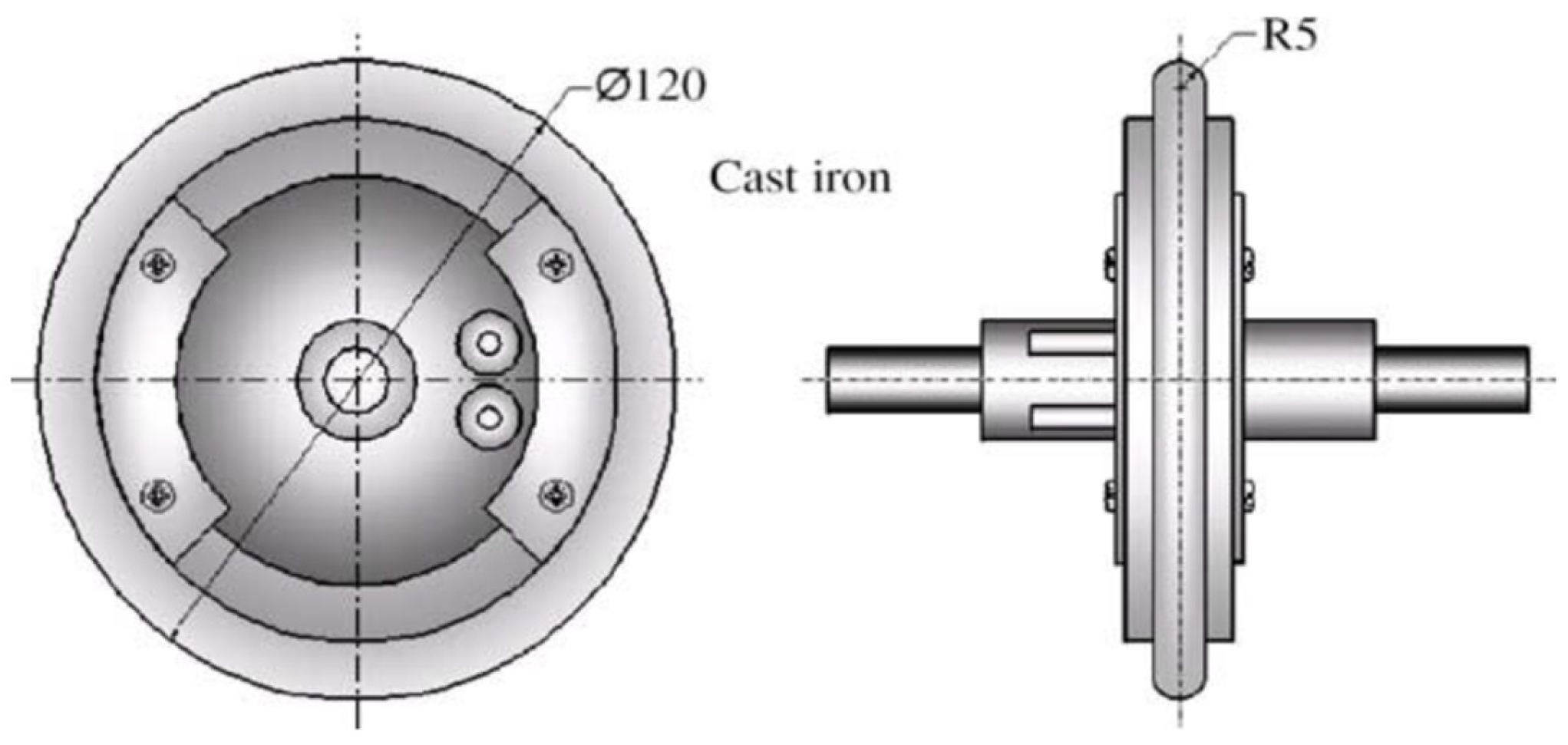
An alternative to direct heating of the blank is heating through the tooling (e.g., mandrel, rollers, or both) such that the workpiece is heated via conduction during spinning. Murata et al. [18] developed a CNC spinning machine equipped with heated roller tools specifically designed for the compression spinning of circular AZ31 magnesium tubes (Figure 13). The rollers were heated by nichrome wire elements embedded on both sides of the rollers, reaching preset temperatures up to 400 °C before the spinning process. The authors reported that the system was capable of achieving stable forming conditions without requiring external heating like gas burners or other auxiliary heating sources. The main drawback of this system lies in its low attainable temperature, thereby limiting applications to low-melting-point alloys like magnesium and aluminum.
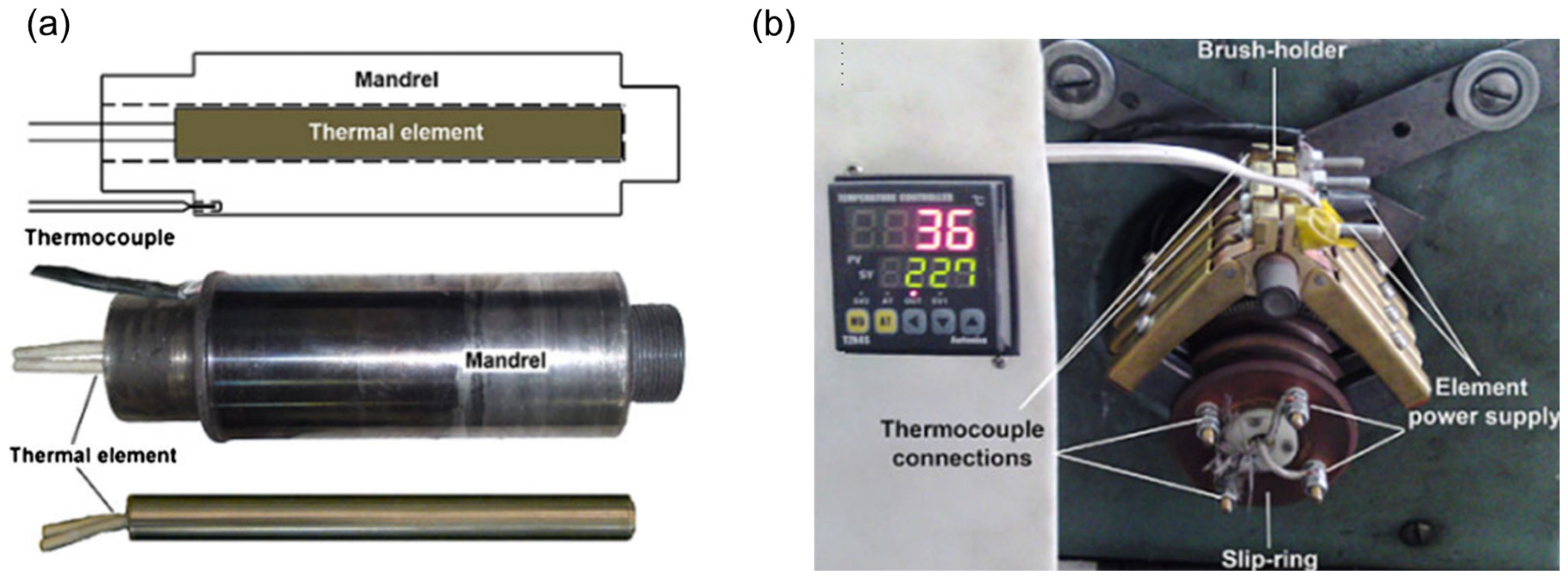
Mohebbi and Akbarzadeh [68] employed electric heating elements embedded into the mandrel to maintain stable forming temperatures for spin bonding of composite bimetallic tubes (Cu/Al) at 230 °C (Figure 14). They installed a thermocouple close to the surface of the mandrel to monitor the temperature. Similarly, Fong et al. [69] conducted flow forming of AZ31 magnesium alloy in a temperature range from 50 to 300 °C through a 130 W electric heater embedded into the mandrel. They found that the forming temperature of the workpiece can be maintained at approximately ±10 °C by using a closed-loop temperature controller; however, a preheating stage must be carried out before forming, decreasing the effectiveness of this method.
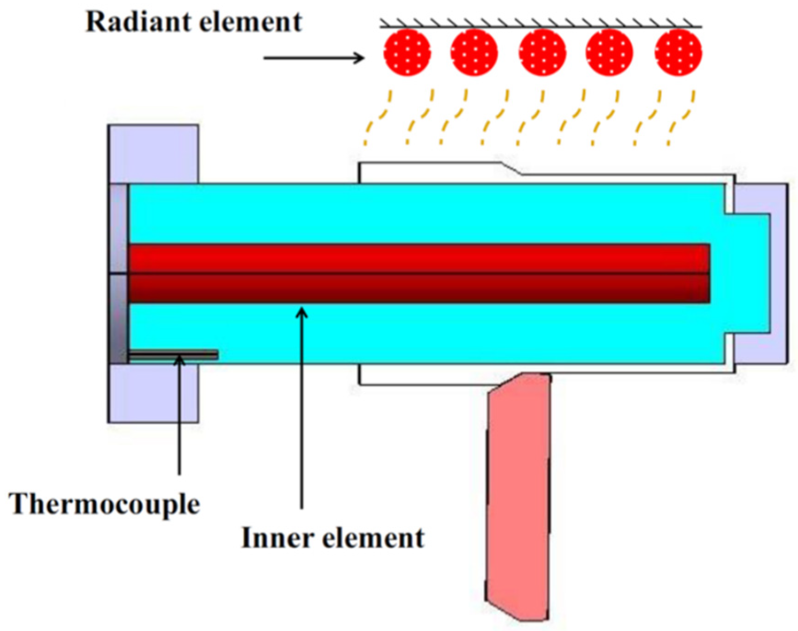
Fata et al. [70] conducted hot flow forming in AZ31 tubes using a dual-heating system, with an electric cartridge heater inside the mandrel and an annular radiant coil outside the blank (Figure 15). The authors tested thickness reductions from 30% to 80% at predefined temperatures between 100 °C and 500 °C. A K-type thermocouple embedded in the mandrel connected to a simple controller was used to regulate the temperature. Although they added a radiant coil aimed to reduce through-thickness temperature gradients, monitoring the outer surface with a thermocouple or infrared camera would help verify this effect and could improve upon the ±10 °C gradient reported by Fong et al. [69] for mandrel-only heating. Recording the heat-up time would also clarify whether preheating the mandrel could shorten the overall process cycle.
In a recent publication, Wu et al. [23] tested a similar rotating electric heating setup for flow forming, combining flame heating for the rollers and electric heating for the mandrel, allowing them to reach a stable temperature between 393 °C and 410 °C. They showed that combining such methods can improve thermal uniformity, though the temperature in the deformation zone may still fluctuate when contact pressure changes or frictional sliding intensifies.
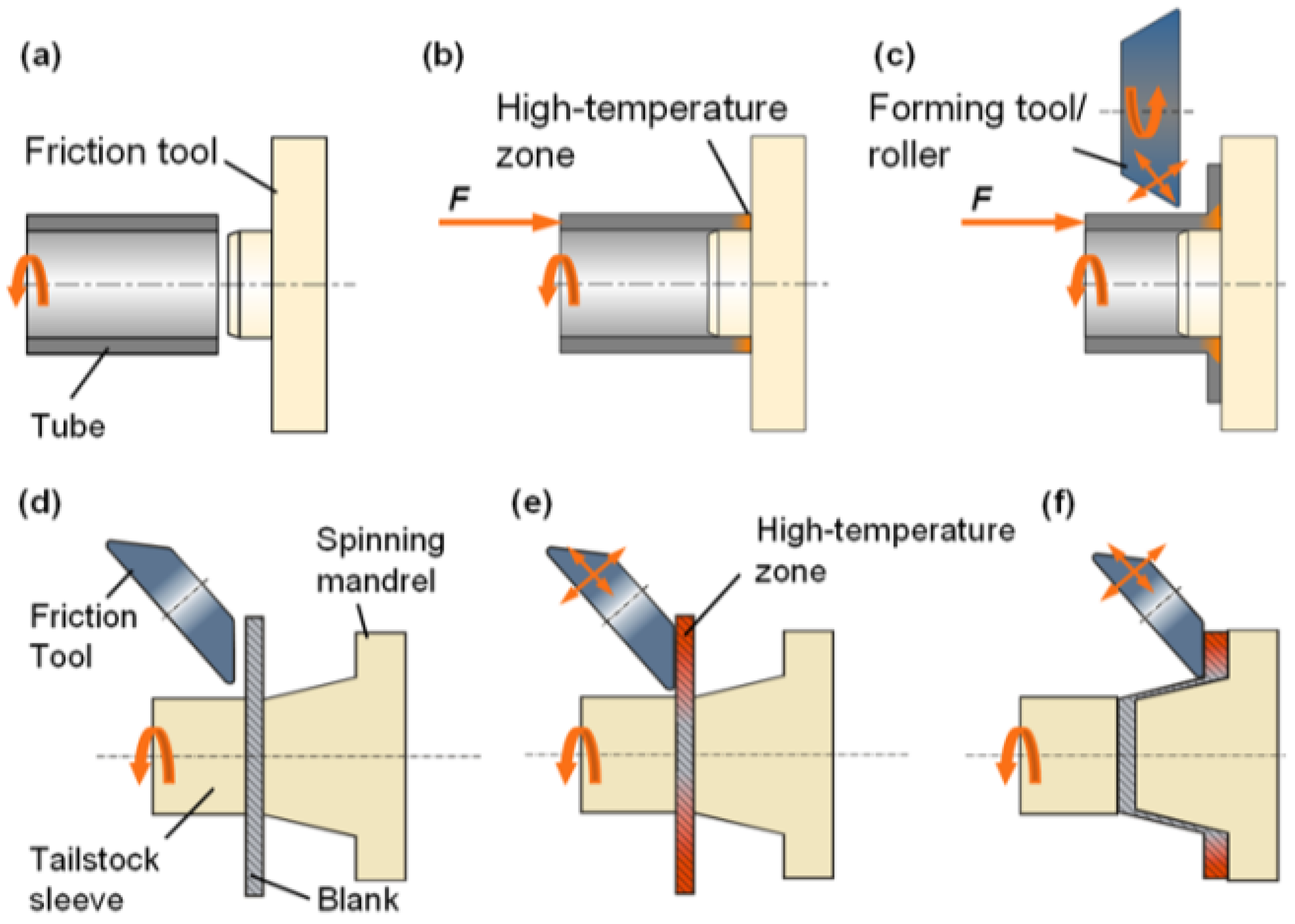
Alternatively, frictional heating could be considered as a tooling heat source because it is technically generated by the contact between the roller or mandrel and the blank, resulting in elevated temperatures in the deformation zone (Figure 16). Although friction-based methods are energy-saving in principle, they are typically hard to control, can lead to surface damage, and may promote large residual stresses due to uneven heating [31,71,72].
Heated tooling presents a straightforward solution for maintaining stable and uniform forming temperatures in hot spinning processes, especially in flow forming, where different studies have been focused. Compared to induction or laser heating, heated tools provide a simpler and energy-efficient approach at lower cost, but they may be limited in temperature range and heating precision.

2.7. Comparison of Heating Methods

In many industrial and research setups, hybrid approaches combine preheating (e.g., furnace or induction) with in-process localized heat (e.g., laser, torch, or heated tools). These strategies aim to mitigate the rapid cooling that occurs when the blank transitions from a heated environment to spinning conditions [31]. Although various heating systems are available for hot spinning, there is no single obvious solution; choosing the optimal strategy depends on several technical, material and economic factors. Technical factors include the required forming temperature, heat-up speed, heating precision and uniformity, process integration, and equipment compatibility. Material-related factors involve the alloy’s thermal conductivity, reflectivity, formability window, melting temperature and microstructural sensitivity to heat. Economic considerations cover equipment cost, energy consumption, production volume, cycle time, and the number of parts to be produced. Table 1 provides a brief comparison of different heating methods to help select the most suitable strategy for each specific application.
Temperature measurement in the deformation zone is a challenging but essential aspect of hot spinning, as the accuracy of the measurement directly determines the quality of the temperature control and, ultimately, the final properties of the spun part. Two main types of temperature sensors were identified. The first are contact sensors, mainly K-type thermocouples embedded in the mandrel [56,69,70,74] or welded to the outer surface of the blank [56]; and the second are non-contact sensors, such as infrared pyrometers [21,29,54,66] and thermal imaging cameras [58]. Contact sensors offer good accuracy and fast response, but their use is limited to stationary parts, such as the mandrel, since placing a thermocouple on a rotating blank is impractical during the spinning operation.
On the other hand, non-contact sensors are better suited for rotating workpieces and have been used in combination with closed-loop control of the heating power, as demonstrated by Brummer et al. [29] for laser-assisted spinning and Imamura et al. [58] for induction heating. However, non-contact measurements require careful calibration of the surface emissivity, which may change during the process due to oxidation, scale formation, lubricant burn-off, or the presence of graphite coatings used to improve laser absorption [67]. In addition, the measurement spot of a pyrometer is typically placed next to the deformation zone itself, so the reported temperature is often an approximation rather than the exact value in the contact region. These limitations explain why many studies report a discrepancy between the set-point temperature and the actual temperature at the roller contact [60], and why some authors have adopted dual-measurement strategies combining thermocouples in the mandrel with pyrometers on the blank surface to improve reliability [29,56,66]. Future work in this area should focus on the development of more robust in situ measurement techniques, such as high-frame-rate thermal cameras with emissivity correction that can track the full temperature field during spinning rather than a single point.
Regardless of the heating method, three distinct thermal zones can be identified during hot spinning. The first is the local heating area, where the external heat source raises the material temperature ahead of or next to the forming zone; the second is the tool–workpiece contact zone, where the roller compresses the material and simultaneously acts as a heat sink, drawing heat away from the deformation region; and the last is the post-contact region, where the material cools through convection, radiation, and conduction into the mandrel. The temperature gradient between these zones is governed by the spindle speed, feed rate, heating power, and the thermal conductivity of the workpiece and tooling materials. As discussed above, several authors have shown that the contact zone typically experiences a temperature drop of 20–50 °C relative to the heated zone [31,54,56], with the magnitude depending on the roller material, contact duration, and lubrication conditions. Minimizing this temperature drop is essential for maintaining uniform formability and preventing localized defects in the spun part. Therefore, independent of the selected heating method, ensuring uniform temperature across these three zones, minimizing thermal gradients, and integrating robust feedback-control systems remain among the most important technical challenges to achieving high-quality spun components.

3. Material Behavior in Hot Spinning

The main focus in advanced metal forming technologies lies in achieving both high geometric precision and superior physical properties at the same time. In this sense, understanding the material behavior during hot spinning is essential, as it directly affects the formability of the spun components, as well as their final mechanical performance.
This section aims to provide a comprehensive discussion on how important the influence of material behavior is and how it is linked to hot spinning conditions. Specifically, it will review and analyze the relationships among spinning parameters, deformation mechanisms, and their consequent impact on mechanical properties such as strength, ductility, hardness, and residual stresses. Microstructural changes induced during hot spinning, although intrinsically linked to material behavior, will be summarized here only insofar as necessary to explain observed mechanical responses. A detailed discussion on microstructural evolution will be reserved for Section 7. Thus, the scope of this section is to establish the fundamental connections between hot spinning conditions and mechanical properties, highlighting key experimental findings from the literature to guide process optimization and future research directions.

3.1. Importance of Material Behavior During Hot Spinning

An in-depth understanding of material behavior at elevated temperatures is essential in hot spinning, as it directly affects formability, force requirements, and the final properties of the spun part. The material response to heat determines how it deforms under spinning forces and how its microstructure evolves during processing [20,33,75].
In contrast to cold spinning, where work hardening (WH) dominates the deformation response, the mechanical and metallurgical behaviors in hot spinning are governed by complex dynamic interactions among temperature ( T ), strain rate ( ε ˙ ), stress state ( σ ¯ ), plastic strain ( ε ¯ ), and microstructure [22]. Typically, the methodology to study recrystallization at certain conditions (e.g., temperature, strain rate, and plastic strain), comes through mechanical testing (e.g., hot compression and tensile tests) and analysis of the flow curves to further correlate them to the microstructure evolution by observation with optical or electronic microscopy [21,61,76]. Selecting the optimal forming temperature requires careful analysis of high-temperature material behavior. Once the suitable thermal processing window is identified, other process parameters, such as spinning speed, feed rate, and reduction per pass, must be adjusted to ensure the part can be successfully formed [62,63].

3.2. Mechanical Tests Related to Spinning Parameters

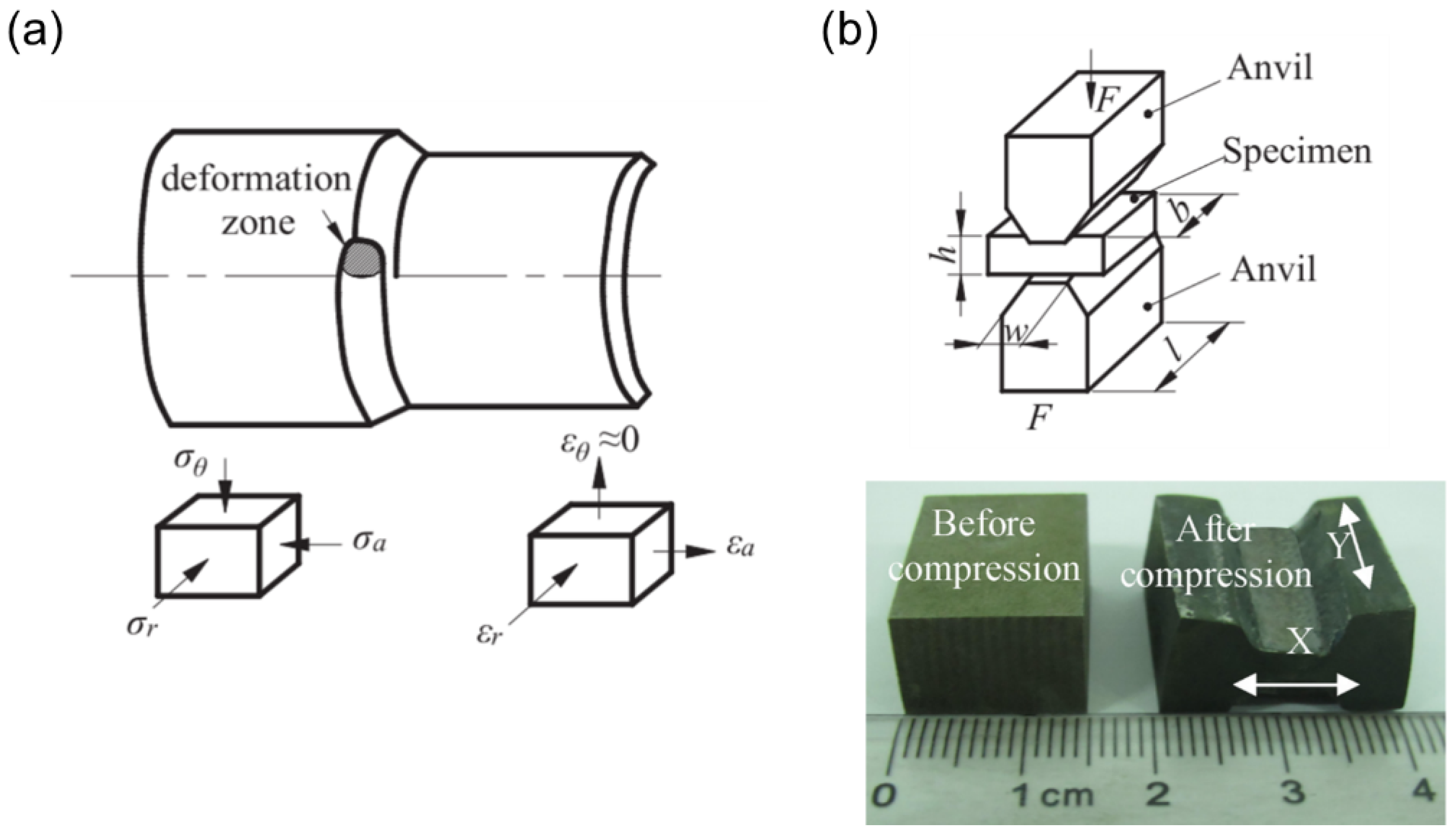
The key point when selecting the mechanical testing conditions to find the optimal forming parameters, including temperature, relies on the characterization of the material in the closest conditions to the forming process. Typically, hot tensile tests have been adopted to investigate the deformation characteristics during hot forming processes, including hot spinning [21,61]. However, the ductility shown for most metallic materials in this condition is not enough to reach the equivalent strain given in spinning processes ( ε 0.3 ); therefore, hot compression tests have been adopted instead [62]. Within compression tests, there are different variants that induce different compressive stress states. In the case of flow forming, it has been reported that the deformation state in the forming zone can be treated as plane strain (Figure 17a). In this sense, Xiao et al. [62] derived the hot processing map of Haynes 230 alloy by an isothermal plane strain compression (see Figure 17b) and identified a processing window ( ε ˙ < 0.3 , T > 1050   ° C ) that guides the appropriate selection of the process parameters ( f   =   0.6   m m / r e v , ω = 100   r p m , T   =   1100   ° C and Ψ t   =   80 % ) for hot backward flow forming.
Furthermore, Xia et al. [63] employed a uniaxial compression test to derive the 3D hot processing maps for the ZK61 magnesium alloy. The material behavior was studied up to a true strain of 1.2 and in a temperature range of 250–400 °C and strain rates of 10 3 10 1   s 1 . They reported that the optimal process parameters to produce thin-walled cylindrical parts with longitudinal inner ribs through hot backward flow forming were f   =   0.4   m m / r e v , T   =   300   ° C and Ψ t   =   65 % . Those conditions led to a good forming quality and a uniform and fine recrystallized microstructure. Similarly, Xu et al. [77] conducted a hot compression test in TA15 titanium alloy to find the warm forming temperature for flow forming. Even though the mechanical characterization showed that the suitable forming temperature was between 900 and 1000 °C, the authors reported that they successfully spun cylindrical parts in warm conditions (600–700 °C), helping to prevent hydrogen intake and surface oxidation.
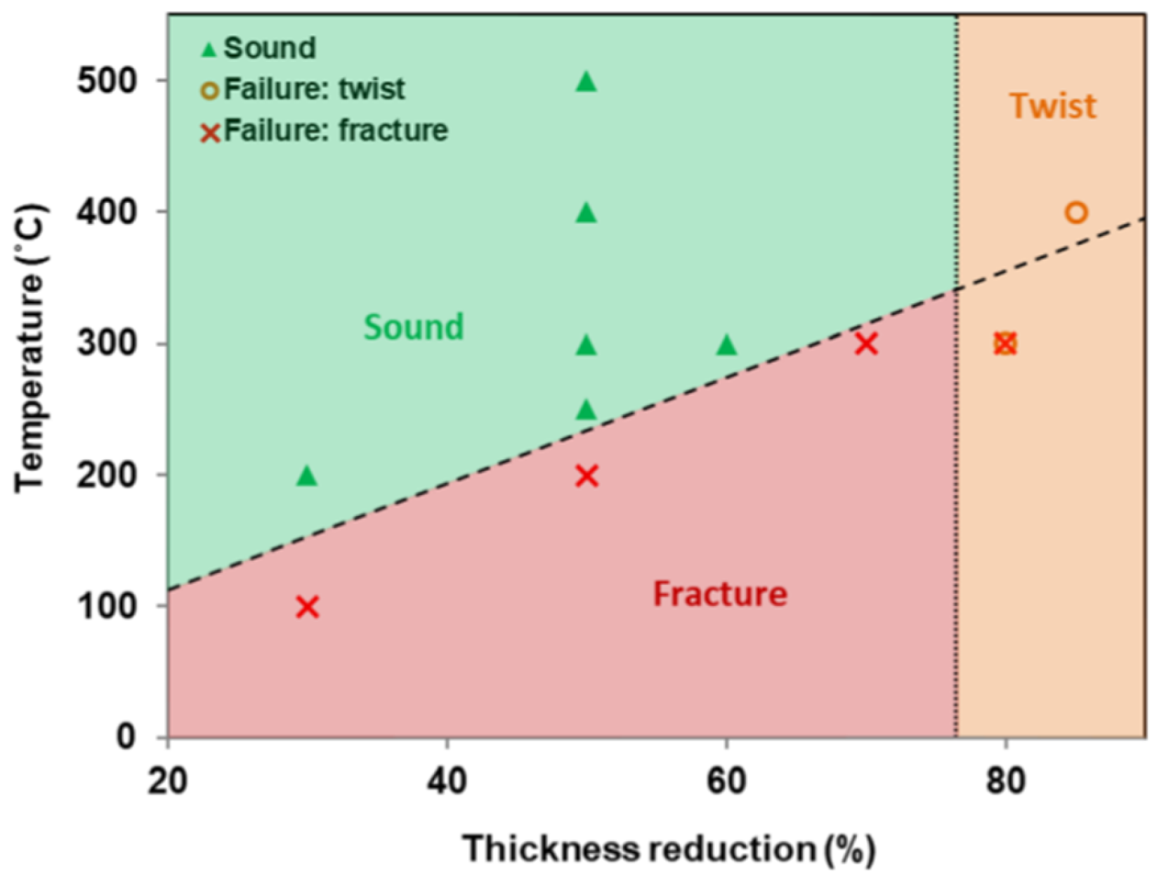
Direct derivation of the processing map by screening different spinning conditions is another alternative that has been used by some researchers. For instance, Fata et al. [70] conducted a formability test for hot flow forming in a temperature range between 100 and 500 °C on AZ31 magnesium alloy (Figure 18). They found that in the interval 200–500 °C it was possible to obtain a sound product, with a limit of 76% in thickness reduction and proper tensile properties, resulting from a grain refinement at 300 °C due to DRX.

3.3. Material Behavior After Hot Spinning

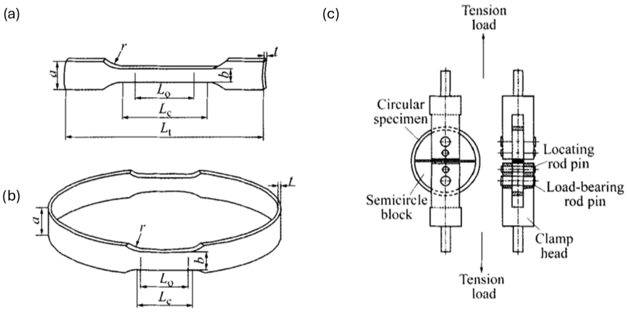
The mechanical properties of spun parts after processing are critical since they define the performance under service conditions. For modern engineering applications, producing an accurate final shape alone is not sufficient; the parts must also meet specific mechanical requirements. In this sense, Xu et al. [78] investigated the tensile strength and elongation of TA15 alloy after hot spinning with varying degrees of thickness reduction, followed by post-spinning annealing. The cumulative thickness reduction reached approximately 80%. Mechanical properties were assessed using conventional tensile testing for axially cut samples and an improved method designed specifically for tubular specimens tested in the circumferential direction (Figure 19). They observed that after spinning, tensile strength increased by approximately 22% in the axial direction and 15% in the circumferential direction, while elongation decreased by about 18% and 53%, respectively. After subsequent annealing at 700 °C, ductility partially recovered, improving by roughly 15% axially and 33% circumferentially, with only a slight reduction (about 5%) in tensile strength in both directions. Their study provides clear, quantitative evidence that hot spinning increases strength at the expense of ductility due to microstructural refinement. The ability to enhance mechanical properties in both axial and circumferential directions is particularly valuable for aerospace components subjected to multi-axial loads. Moreover, the observed recovery in ductility with minimal loss in strength after annealing below the recrystallization temperature offers a useful guideline for designing appropriate post-processing heat treatments.
Mori et al. [21] emphasized the importance of achieving adequate final mechanical properties after spinning, especially for cast aluminum alloys used extensively in the automotive sector. They measured tensile strength and elongation after hot shear spinning followed by aging heat treatment. Their results indicated that this combined spinning and heat treatment process improved tensile strength by approximately 16% and significantly increased elongation by around 114%. They reported that hot shear spinning effectively enhances the mechanical properties of cast aluminum alloys by eliminating typical casting defects and improving material strength.
In a similar study, Han et al. [60] analyzed the trade-off between strength and ductility under different hot spinning conditions in the work-hardening 3A21 aluminum alloy. They determined that optimal properties were achieved by spinning at temperatures between 240 and 280 °C with a thickness reduction of 30%, followed by post-spinning annealing at 400 °C. This approach modestly improved strength by 5% but significantly increased elongation by 46%, compared to the initial material state. Similarly, Romero et al. [64] investigated the mechanical properties of dual-phase steels DP600 and DP780 after flow forming. They evaluated Vickers microhardness and tensile strength by employing a hoop tensile test similar to Xu et al. [78]. Their findings indicated that hardness increased from 250 HV to 300 HV for both cold and laser-assisted spinning, attributing the increase primarily to plastic deformation resulting from the 50% thickness reduction rather than to temperature-induced phase changes. Furthermore, they studied two spindle speeds (600 rpm and 1000 rpm) and observed that higher speeds negatively affected mechanical properties. Although Romero et al. [64] did not define an optimal spinning route, their results clearly demonstrated an improved forming window and enhanced post-forming performance, which are particularly relevant for automotive applications of dual-phase steels.
Cao et al. [79] conducted a comprehensive study to identify optimal processing parameters that achieve the best balance between strength and ductility. They evaluated three different feed rates (0.07 mm/rev, 0.1 mm/rev, 0.15 mm/rev, and 0.25 mm/rev), three temperatures (300 °C, 350 °C, and 450 °C), three spindle speeds (200 rpm, 400 rpm and 600 rpm), and three thickness reductions (15%, 30%, and 45%). The authors observed an unexpected influence of feed rate on ductility, which increased at 0.1 mm/rev but decreased to 0.15 mm/rev. A similar trend was noted for thickness reduction, with ductility increasing from 6% at 15% thickness reduction to 12% at 30%, before decreasing at 45% thickness reduction. Although the authors attributed this behavior to microstructural homogeneity, further statistical analysis is required to confirm this trend.
Brummer et al. [29] demonstrated the potential of optimizing mechanical properties after spinning by applying a localized heating source, specifically using a laser. They evaluated hardness evolution for three alloys: stainless steel X5CrNi18-10, Ti Grade 2, and Inconel 718. Their results showed a significant increase in hardness across various conditions. For stainless steel spun at 600 °C with a 44% thickness reduction, hardness increased from 160 HV1 to 300 HV1 (88% increment), and at elevated temperatures of 900–1000 °C, hardness for Inconel 718 increased from 209 HV1 to 440 HV1 (111% increment) at 900 °C, with slightly lower values at 1000 °C. The hardness increment was strongly correlated with wall thinning, confirming that plastic deformation primarily drives hardening behavior even at elevated temperatures. This effect was attributed to the localized concentration of heat in the deformation zone.
During hot spinning, multiple processing routes may be combined, involving heating steps conducted either before, during, or after the forming operation. For instance, Maj et al. [80] explored an alternative processing route for Inconel 718, consisting of cold flow forming of pre-formed cups, followed by a standard aging heat treatment (750 °C for 8 h). Their results indicated that immediately after flow forming, ductility sharply dropped to very low values (1.5–3.5%), but significantly recovered after aging, reaching between 21% and 28%. However, the resulting mechanical strength (approximately 1062 MPa yield strength) fell slightly below the typical aeronautical requirement of 1100 MPa, emphasizing the importance of carefully balancing work-hardening and precipitation-strengthening mechanisms.
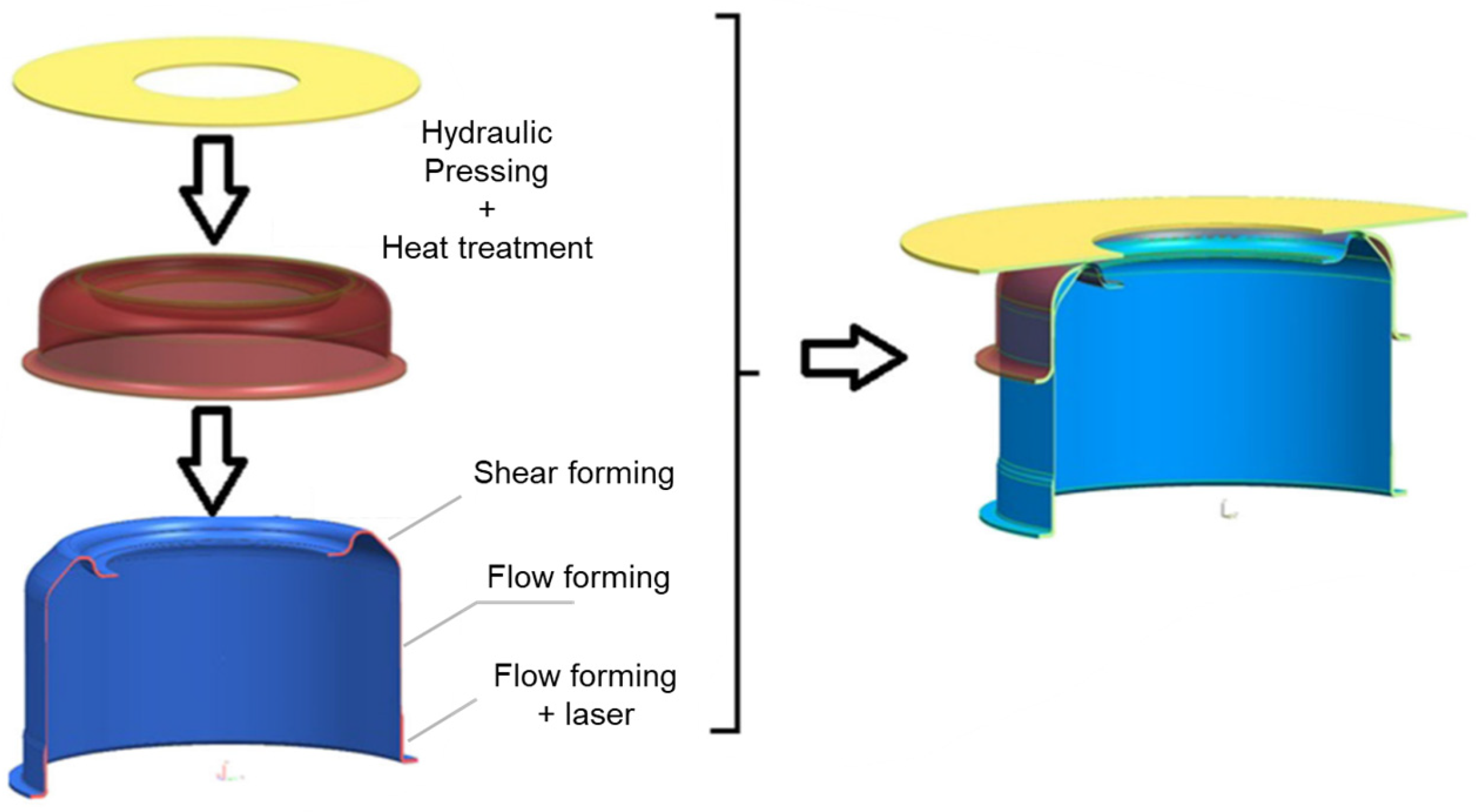
In a subsequent study, Maj et al. [81] refined this methodology further by comparing conventional furnace post-spinning precipitation to an innovative laser-assisted flow forming approach applied to Inconel 625. Their intricate process comprised multiple stages: hydraulic pressing, heat treatment, shear spinning, flow forming, and selective laser-assisted spinning (Figure 20). Each step strategically targeted areas susceptible to cracking, selectively applying localized heating. The results showed that the laser-assisted spinning region achieved the best overall balance among ductility, strength, and processing time, although mechanical properties were slightly lower than those obtained through conventional furnace-based heat treatment. While specific laser parameters were not detailed, the authors indicated that further optimization of laser power and heating duration could improve mechanical properties even more. Their study underscores the versatility of hot spinning processes and their potential advantages over traditional processing methods, particularly for manufacturing high-performance alloys intended for demanding industrial applications.

3.4. Residual Stresses

Understanding and evaluating residual stresses after hot spinning processes is crucial due to their significant impact on the mechanical performance and durability of components. Residual stresses can lead to distortion, premature failure, reduced fatigue life, and stress corrosion cracking if not adequately controlled or relieved [82,83]. Hot spinning generally presents advantages over cold spinning, such as reduced residual stresses due to the improved plasticity at elevated temperatures, facilitating easier material flow and less intensive stress accumulation [64]. However, significant residual stresses may still persist, necessitating careful assessment and potential post-processing treatments [84].
Residual stress gradients were identified by Mori et al. [21], who confirmed that carefully optimized annealing treatments after hot shear spinning substantially relieved residual stresses, while preserving beneficial microstructural features developed during the spinning process. Their work underscored the delicate interplay between maintaining mechanical strength and achieving sufficient stress relief to avoid potential structural issues in aluminum alloys used in automotive applications. Romero et al. [64] studied laser-assisted spin forming of dual-phase steels at ~350 °C. Residual stresses were measured by X-ray diffraction (XRD) at a representative 1500 rpm condition; the laser-assisted sample showed lower-magnitude compressive residual stresses than the cold spun sample, which was attributed to the thermal-softening mechanism that absorbed part of the permanent strain during forming. At low spindle speeds the laser also reduced mechanical power by ~15–20% and improved ring-hoop tensile response. At high speeds, power reduction was not observed but lower residual stress and reduced failure risk were still reported, consistent with DRV/DRX observed by Electron Backscatter Diffraction (EBSD) and Transmission Electron Microscopy (TEM) in the laser-heated zone. Overall, Romero’s XRD results show that modest, well-placed heating (~350 °C at the surface) can reduce residual-stress magnitude in DP steels without detrimental microstructural change.
Maj et al. [81] demonstrated the substantial differences in residual stress resulting from various heat treatments during the flow forming of Inconel 625 cylinders. Utilizing XRD, they identified high residual stress concentrations near surfaces in cold-formed parts, leading to crack initiation. In contrast, laser-assisted heating significantly reduced these stresses by facilitating dislocation rearrangement and recrystallization. This illustrates the critical advantage of localized heating in managing residual stress distribution, thereby reducing the risk of premature failure.
Future trends and research opportunities involve integrating advanced numerical simulation and digital twins with IA monitoring technology to mitigate residual stress in situ. Furthermore, exploring hybrid heating approaches combining localized moving heat sources with traditional treatments could offer promising pathways to optimize both residual stress management and final mechanical properties.

4. Influence of Process Variables in Hot Spinning

In hot metal spinning, process parameters dictate the quality of the final component. Although many of the parameters (e.g., feed rate, spindle speed, thinning ratio, and tooling geometry), might have a clear effect on cold spinning [3,12,85], their influence becomes more complex under hot conditions, due to thermo-mechanical coupling [45]. This section provides a critical overview of how these variables affect the quality of the final component and offers guidance for selecting appropriate parameters, while highlighting distinctions among flow forming, shear spinning, and conventional spinning.

4.1. Temperature: Flow Stress, DRV/DRX, and Defects Thresholds

Temperature is by far the most critical parameter influencing part quality during hot metal spinning. Unlike cold spinning, where strain rate effects are almost negligible, hot spinning exhibits a strong thermo-mechanical coupling, significantly affecting geometric precision and defect formation due to the visco-plastic behavior that most metallic materials show when temperature is increased [45].
On the other hand, deformation is dominated by work hardening (WH) at low temperatures, leading to high deformation resistance and limited material ductility, thereby increasing the likelihood of cracking. Increasing the temperature activates dynamic recovery and dynamic recrystallization, which progressively replace work hardening as the dominant mechanism at the microstructural level. This shift reduces flow stress, increases ductility, and consequently lowers the likelihood of crack formation during spinning [45]. For instance, Klocke and Wehrmeister [17] and Brummer et al. [29] demonstrated that hot spinning can lead to successfully spun alloys that would not be possible at room temperature (Figure 21). Furthermore, they showed that alloys with a high strain hardening capacity, like Inconel 718 and X5CrNi18-10 stainless steel, can be formed without any intermediate annealing steps at lower loads, thus increasing productivity.
Beyond avoiding cracking, temperature also drives microstructure evolution. It is well-known that DRX is temperature-, strain- and strain-rate-dependent [86,87]. Therefore, when forming temperatures reach levels suitable for DRX microstructure refinement becomes critical [22,49]. For instance, Long et al. [22] observed complete DRX and refined grain structures between 1100 and 1200 °C for Haynes 230 alloy during flow forming, that significantly enhanced microstructural homogeneity and mechanical properties. On the other hand, Yoshihara et al. [52] and Yang et al. [28] explored the impact of forming temperature on the spinning of magnesium alloys. Both studies independently concluded that forming temperatures close to 300 °C significantly enhance ductility by activating DRX. Additionally, maintaining the temperature around 300 °C was found effective in preventing excessive oxidation, a common issue at higher temperatures, thus preserving the surface quality and structural integrity of the formed parts. The details of the microstructure evolution are further analyzed in Section 7.
Experimental studies have consistently identified temperature windows that balance formability, mechanical performance, and defect mitigation for different alloy families. For nickel-based alloys, temperatures in the range of approximately 1000–1200 °C have provided optimal formability and defect-free spinning [49,76]. Magnesium alloys exhibit optimal performance at much lower temperatures, typically between 200 °C and 450 °C, as this range ensures sufficient ductility and the activation of DRX without causing excessive oxidation or grain coarsening [31]. Titanium alloys have shown favorable spinning characteristics within the range of 450–800 °C, providing an ideal balance between ductility enhancement and surface integrity [17,29].
For aluminum alloys, spinning temperatures typically fall within 200–400 °C, depending on alloy composition and specific process conditions [56,60]. Lower forming temperatures (~200–280 °C) generally improve ductility through moderate DRV and DRX, minimizing defects without inducing significant grain growth or oxidation. Higher temperatures (300–400 °C) may be beneficial for certain alloys or larger deformation, though careful control is required to prevent surface oxidation, coarse grain structures, or geometric inaccuracies resulting from excessive softening.

4.2. Feed Rate: Strain Rate, Heat Generation, and Risks of Defects

Feed rate, typically expressed in millimeters per revolution (mm/rev), also has a profound influence on the formability and final geometry of spun parts. Under cold spinning conditions, feed rate is often considered as the most important parameter in defect generation and dimensional accuracy [85]. However, in hot spinning processes, increasing the feed rate increases the strain rate and local heat generation, increasing the risk of surface cracks if temperature gradients become too large [22]. For many alloys, moderate feed rates reduce grain size by boosting DRX nucleation, though feed rates that are too high may shorten contact time, worsen temperature gradients, and induce wrinkling [69,88]. Specific optimal ranges may depend on the material, roller nose radius, blank thickness and temperature.
Long et al. [22] and Xia et al. [76] demonstrated that feed rates between 0.4 and 0.8 mm/rev significantly enhance grain refinement and enable defect-free forming of Haynes 230 when using a roller nose radius of 4 mm and an initial thickness of 5 mm. For magnesium alloys, Yoshihara et al. [52] and Cao et al. [79] reported that feed rates ranging from 0.2 to 0.6 mm/rev help to prevent local thinning and ensure uniform deformation, particularly in tubes with thicknesses from 3 to 6 mm and roller nose radii around 20 mm. On the other hand, Yin et al. [89] found that feed rates exceeding 1.0 mm/rev may trigger excessive shear deformation and insufficient contact time, negatively impacting dimensional accuracy. Furthermore, Li et al. [75] reported in flow forming studies that feed rates above 1.5 mm/rev may degrade surface quality, although they can improve productivity.
Additionally, Han et al. [88] and Xia et al. [49] emphasized that frictional heat generation is strongly influenced by feed rate. As the feed rate increases, frictional and plastic deformation heating accumulates more rapidly than heat dissipation, potentially elevating localized temperatures and increasing the risk of material softening or cracking. Moreover, the above studies highlight the necessity of adjusting heating power relative to the strain rate, as feed rate generally remains constant throughout the operation. This is particularly critical for conventional and shear spinning processes involving disk-shaped blanks, where the radial position, and thus tangential speed, in the contact zone varies significantly. As the radial position increases, even a constant feed rate can produce higher tangential speeds, leading to greater friction and strain rates. These effects must therefore be carefully considered when selecting spinning conditions at elevated temperatures.
Conversely, Li et al. [75] and Fong et al. [69] found that excessively low feed rates, while beneficial for surface quality, typically reduce forming efficiency and increase axial tensile stresses. They also noted that overly slow feeds might cause circumferential cracking due to excessive deformation or repeated roller contact (over-rolling effects). Long et al. [22], Jing et al. [90], and Xiao et al. [33] consistently identified moderate feed rates (0.4–1.0 mm/rev) as optimal, balancing deformation uniformity, minimizing defect formation, and maintaining favorable mechanical properties. Furthermore, Yin et al. [89] and Zheng et al. [91] highlighted that such intermediate feed rates provide sufficient strain energy to promote effective DRX while minimizing dimensional deviations. Therefore, the optimal feed rate selection requires careful consideration to balance the material’s strain rate sensitivity for maintaining desired microstructures, compatibility with heating capability, surface finish requirements, and overall process productivity.

4.3. Thinning Ratio: Local Thinning, Bulging, and Cracking

The thinning ratio refers to the percentage reduction in wall thickness and is directly correlated with the magnitude of plastic deformation. Although a 30–40% thinning ratio is typically manageable for mild steels or aluminum alloys at room temperature, hot spinning processes commonly pursue higher reductions, ranging from 60% to even 80%, to achieve the desired final geometry in fewer passes [60,78]. High thinning ratios accelerate strain hardening in cold spinning, but in hot spinning, DRV and DRX can mitigate such issues if the temperature and strain rate are properly synchronized [22].
Studies by Han et al. [60] and Xia et al. [76] on nickel, titanium, and aluminum alloys demonstrated that thinning ratios exceeding 70% promote the formation of homogeneous grain structures, which significantly enhance ductility. However, Mohebbi and Akbarzadeh [92] and Fata et al. [70] emphasized that excessively large reductions could lead to surface cracking, non-uniform strain distributions, and geometric distortions, particularly if local temperatures are insufficient to sustain uniform plastic deformation. For magnesium alloys, Cao et al. [79] and Zheng et al. [91] established that elevated forming temperatures are necessary to reliably achieve thinning ratios above 60%.
In hot flow forming, the specific thickness reduction per pass is equally critical, with typical values ranging from 25% to 35% recommended to prevent excessive strain accumulation, cracking or bulging [59,76]. Higher cumulative thinning ratios lead to hardness variability and deformation instability [80,93].
Collectively, these results indicate that the thinning ratio should be treated as a process window coupled to temperature and strain rate rather than a fixed target. Closing this gap requires in situ thickness and temperature measurements tied to adaptive control of the feed, spindle speed, and heat input so that the thinning schedule delivers uniform microstructure and shape accuracy.

4.4. Roller Geometry: Contact Control and Shape Defects

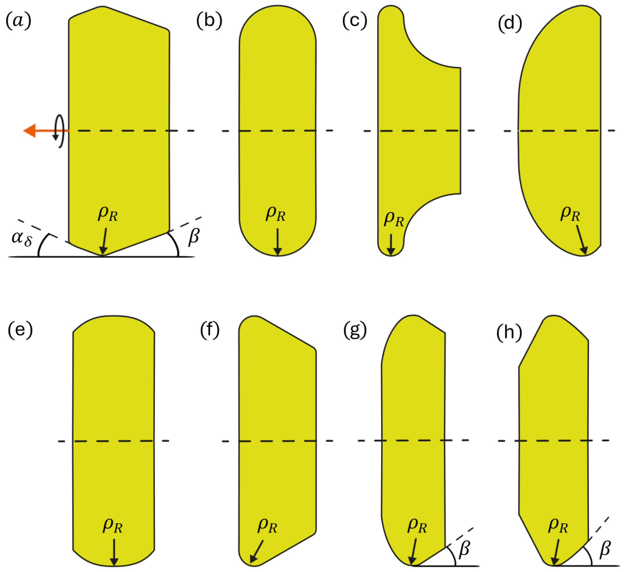
The geometry of the spinning roller controls the contact area in the forming zone, and it might change depending on the spinning process. Typically, in flow forming three rollers are positioned at 120° in the circumferential direction and perpendicular to the tube’s rotational axis in the radial direction. This positioning requires that the profile of the roller differs from those used in shear and conventional spinning (Figure 22). The typical profile of the roller used in flow forming is composed of an inclined entrance with a roller attack angle ( α δ ), followed by a fillet radius ( ρ R ) and then a smoothing angle ( β ), as shown in Figure 22a. On the other hand, the parameter related to the roller’s geometry in conventional and shear spinning is given by the roller nose radius ( ρ R ), roller diameter ( D R ) and roller holder inclination ( δ ). Some variations in the roller’s profile can be adjusted depending on the surface finish that is desired or a particular operation that the spun parts require [1]. Thus, the effect of the roller geometry relies on three main parameters: the attack angle given by the roller holder inclination ( δ ), nose radius ( ρ R ), and diameter ( D R ). All the above parameters strongly affect stress distribution, contact area, heat transfer, and, ultimately, dimensional accuracy and defect appearance.
Yin et al. [89] and Xia et al. [49] noted that a larger roller nose radius generally yields smoother surface finishes and distributes stress more uniformly. However, they also highlighted potential drawbacks, such as a local accumulation of material and an increased risk of wrinkling. Li et al. [94] and Yang et al. [28] demonstrated that a smaller roller nose radius enhances the conformity between the blank and mandrel, reducing gaps and ensuring tighter geometric control. Nevertheless, a smaller radius tends to concentrate strains locally, increasing the likelihood of defects such as bulging or cracking. Consequently, Li et al. [94] and Xia et al. [49] recommended an optimal roller nose radius range of approximately 4–8 mm, depending primarily on the alloy’s softness at the forming temperature, initial blank thickness, and targeted thinning ratio.
The attack angle in the roller’s profile is usually implemented in flow forming because the material flow is mainly in the axial direction. Attack angles likewise influence contact area, axial material flow and spinning force magnitude. Attack angles of about 17–25° can provide stable contacts in flow forming, whereas more aggressive angles might accelerate thinning [75,92]. On the other hand, in conventional spinning and shear spinning, an excessively small roller holder angle increases the axial force, promoting elongated grains and risking wrinkling [20]. Selecting a suitable attack angle, roller holder inclination, nose radius, and diameter is thus a matter of balancing local deformation uniformity, heat transfer, surface roughness, thinning rate and the desired final shape.

4.5. Spindle Speed: Frictional Heating, Stability, and Surface Integrity

Spindle speed in cold spinning typically has a minimal influence on formability or surface quality [85]. However, in hot spinning, it becomes significant due to its direct impact on strain rates and balance between temperature distribution due to heat loss given by the air convection and heating due to friction and plastic strain. Murata et al. [18], Akkus and Kawahara [73], and Gadek et al. [66] demonstrated that moderate spindle speeds between 200 and 600 rpm are effective in managing material flow, reducing strain localization, and ensuring consistent deformation, especially in temperature-sensitive alloys such as magnesium. Li et al. [94] and Fan et al. [71] observed that excessively high spindle speeds can induce undesirable vibrations and surface defects, whereas excessively low spindle speeds may lead to overheating, inefficient production, and reduced part quality.
Cao et al. [79] and Marghmaleki et al. [95] established optimal spindle speeds in the range of 400–800 rpm to minimize cracking, promote uniform grain refinement, and maintain dimensional stability. Furthermore, Fan et al. [71] emphasized that higher spindle speeds can increase productivity through enhanced heating rates, although precise speed control remains essential to prevent material flow instability or other temperature-related defects.
Heat-assisted spinning processes particularly require synchronization between rotational speeds, feed rate and heating power to optimize the temperature distribution for achieving optimal forming conditions. These adjustments are critical for difficult-to-form materials like magnesium, Ni-based and titanium alloys [65,66].

4.6. Summary of Process Parameters and Practical Implications

Despite many shared process variables, flow forming, shear spinning, and conventional spinning each exhibit distinct deformation patterns and sensitivities to hot working parameters. Flow forming generally involves large axial elongation under controlled reductions in wall thickness. Because it relies more heavily on axial movement, feed rate and multi-pass schedules are especially critical for controlling final elongation and microstructure [70,92]. Shear spinning, on the other hand, produces conical or curvilinear shapes with significant shear strains, thus placing heavier demands on roller holder angle, roller nose radius, and friction management. Indeed, the interplay of roller nose radius, thinning ratio, and temperature can be more complex in shear spinning, given its tendency toward localized shear bands if parameters are not well-chosen [94,96]. Conventional spinning operations typically require comparatively modest thickness reductions and rely strongly on roller path strategies to maintain dimensional accuracy. Hot conditions mainly serve to facilitate the process, but the risk of defect formation can be significant when spinning thin-walled geometries without carefully matched speeds and feed rates [31,88].
Beyond process parameters, the geometry of the workpiece plays an important role in the thermo-mechanical response during hot spinning. Thicker blanks require higher heating power to achieve uniform through-thickness temperature, while thinner walls equilibrate thermally faster but are more susceptible to localized overheating and rapid cooling at the roller contact. For conventional and shear spinning of disk-shaped blanks, increasing the blank diameter produces higher tangential velocities at the roller contact, which in turn affects the local strain rate, frictional heating, and convective heat loss. Large diameter-to-thickness ratios reduce the structural stiffness of the unsupported flange, increasing the risk of wrinkling and geometrical distortions [75,97]. Similarly, support conditions influence the thermal and mechanical boundary constraints, such as the mandrel material, its temperature, and the surface quality of the blank–mandrel interface contact, which influence the rate of heat conduction away from the inner surface. Also, clamping arrangements and tailstock pressure affect the rigidity of the workpiece during forming. Several authors have demonstrated that preheating the mandrel [56,69,74] or controlling its temperature independently [6,70] can significantly reduce through-thickness thermal gradients and improve forming outcomes.
Achieving optimal outcomes in hot metal spinning requires careful consideration of combined process parameters. Experimental guidelines recommend temperature control (±20 °C) combined with moderate feed rates (0.4–0.8 mm/rev), optimized thinning ratios (60–70%), and careful selection of roller geometry and spindle speeds to significantly enhance the part’s quality [22,28,60,98].

5. Defects in Hot Spinning

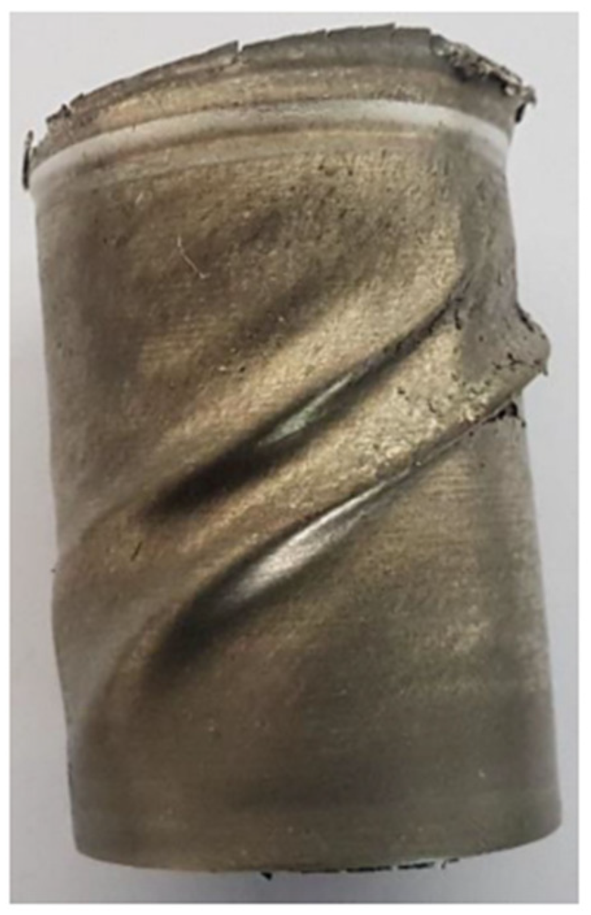
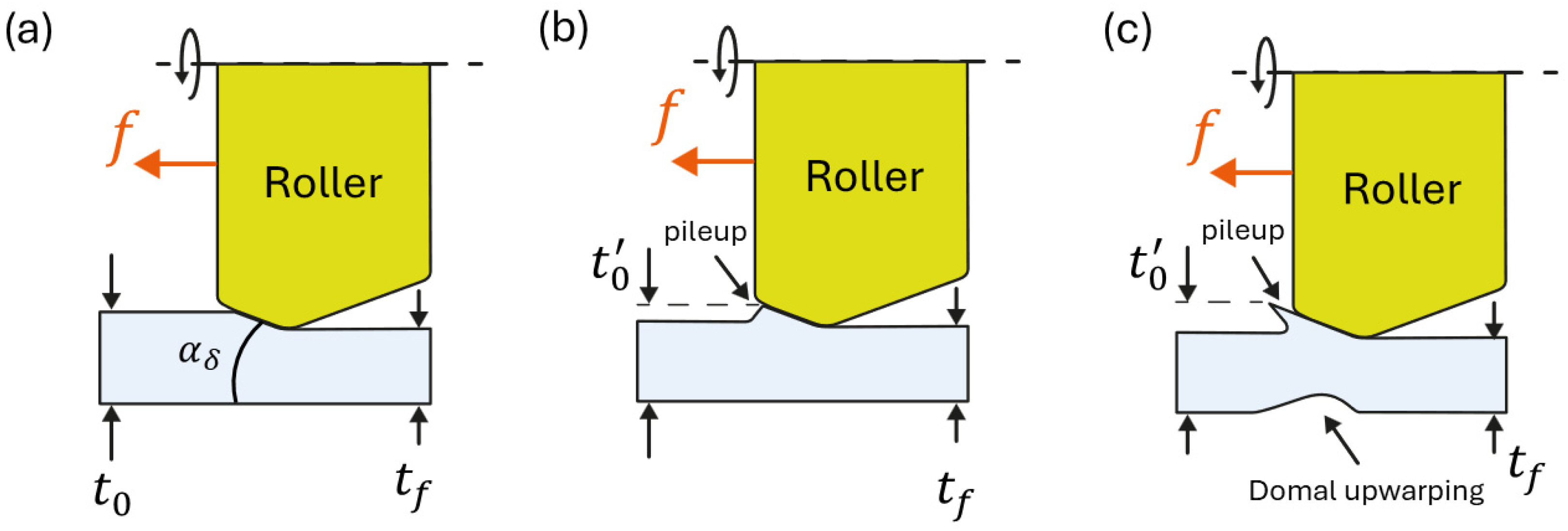
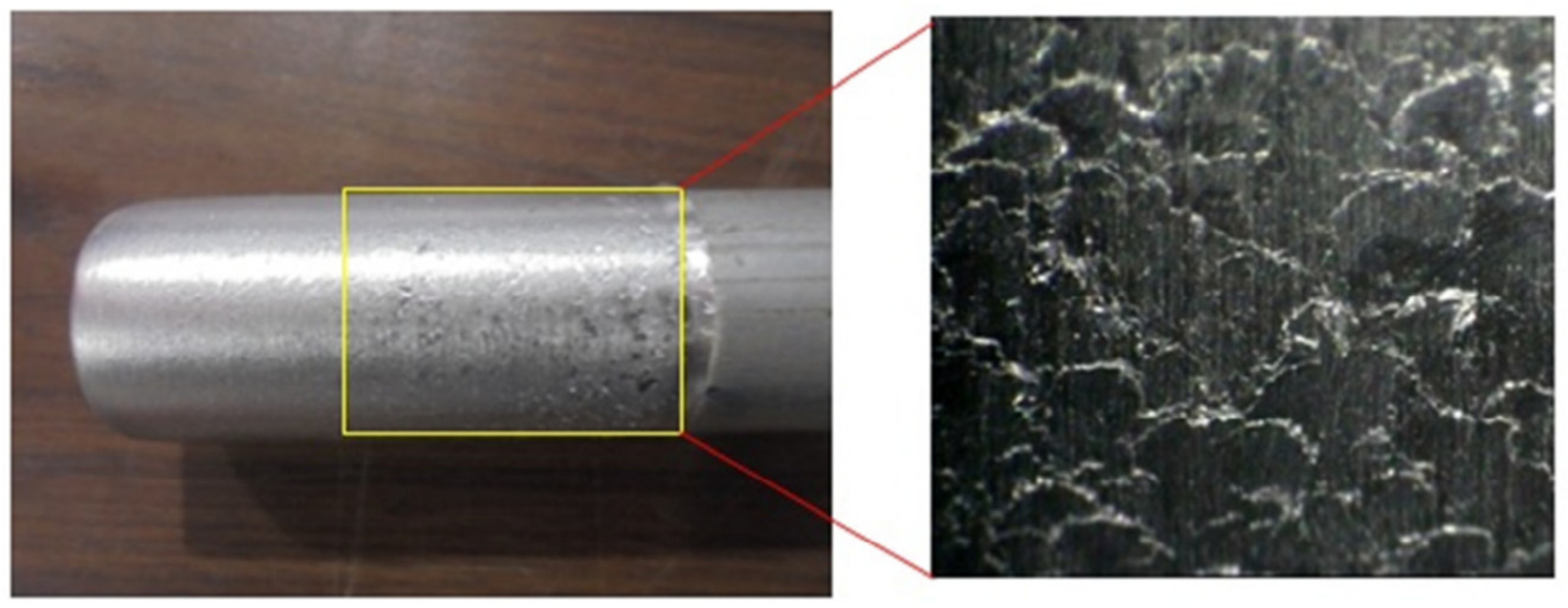
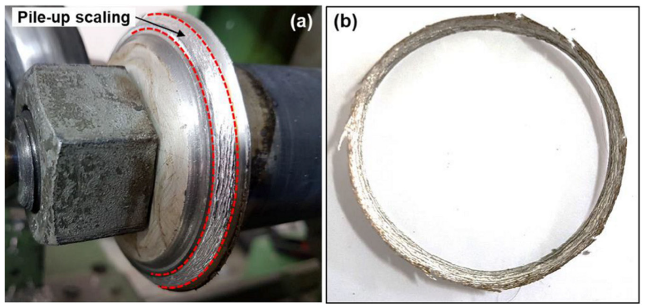
Defects in hot spinning significantly affect the quality, structural integrity, performance and production of spun components. Common defects in hot spinning include surface cracks, wrinkling, thickness variations, surface pile-up, peeling, oxidation, and delamination, as well as geometrical issues such as bulging, warping, diametral growth, and ovality. Although these defects often result from thermal gradients specific to hot spinning, they may also originate from improper selection of processing parameters, low ductility, or unsuitable tooling configurations [45,99]. While extensive literature addresses defects in cold spinning [3,12,44], there is limited understanding of the direct relationship between specific hot spinning conditions and certain defects predominant in hot conditions. Clarifying these relationships through targeted studies could substantially improve defect mitigation strategies. In this section, the various types of spinning defects are described in detail, focusing specifically on their link with temperature conditions, process parameters, and material characteristics.

5.1. Cracking and Temperature Windows to Avoid It

Although cracking typically occurs in cold spinning, surface cracks are also among the most frequently observed defects during hot spinning. Surface cracks in hot spinning originate due to large strain gradients, insufficient ductility, or severe localized shear at the roller–blank interface [45,99]. Excessively rapid deformation, overly aggressive thickness reduction per pass and poor thermal control can further intensify crack formation. These cracks commonly appear on the outer surface of the spun parts, where deformation-induced strains and thermal gradients are more severe than on the inner surface [100].
Several investigations highlight the role of temperature in crack development. For instance, Han and Chen [16] demonstrated that hot flow forming of TAl tubular blanks can suffer from surface cracks due to non-uniform material flow caused by a significant temperature gradient through the thickness. Xu et al. [78] noted that TA15 alloy tubes formed by flame-assisted flow forming displayed frequent surface cracking between 500 °C and 550 °C. At lower temperatures, insufficient activation of slip systems in materials with a hexagonal close-packed structure (e.g., magnesium and titanium alloys) further predisposes the part to surface cracking [18,70].
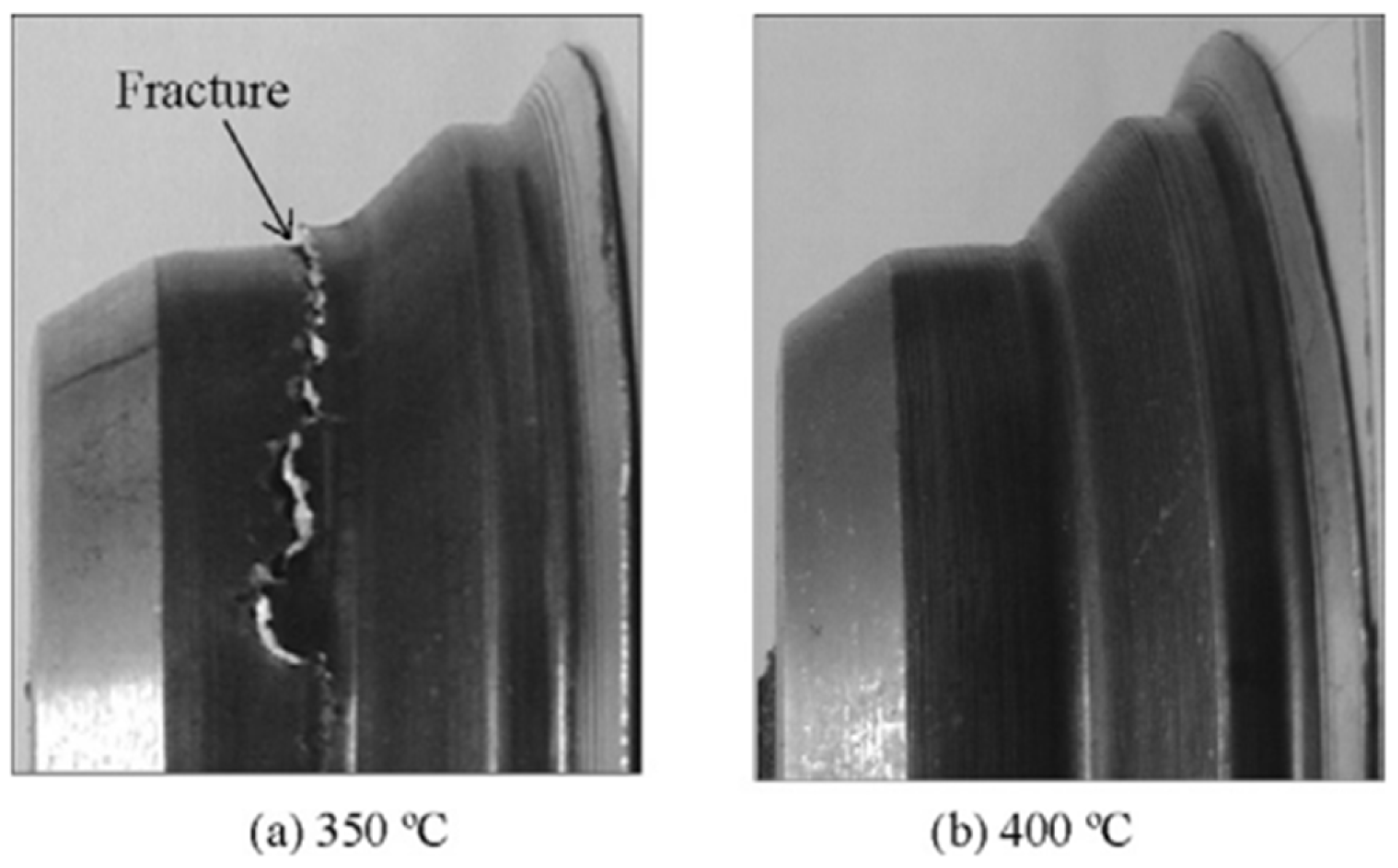
Mori et al. [21] observed cracks around the mandrel corner, an area prone to large shear deformation, during gas convection hot shear spinning of cast aluminum alloy A356. Lowering the roller feed rate and increasing the roller nose radius was able to mitigate this issue, while keeping the temperature around 400 °C. Although the temperature was nominally constant, a lower feed rate inherently increased the processing time, which likely promoted a more uniform temperature distribution and, in turn, reduced the risk of crack formation (Figure 23). Roy and Maijer [56] described similar localized shear-driven “fish-scaling” cracks in the same alloy in flame-assisted wheel flow forming, which propagate along eutectic-rich regions due to stress gradients. They showed that increasing the forming temperature from 350 °C to 400 °C prevented these cracks by reducing radial shear stresses. This 50 °C interval, however, was not further subdivided in the study, so the precise temperature increase needed to ensure a defect-free product is not known, highlighting the need for accurate temperature measurement and finer-resolution experimental mapping in the deformation zone.
Han et al. [60] reported cracks below 200 °C in an AA3033 aluminum alloy, showing that inadequate forming temperature may also induce surface microcracks, and ultimately, crack propagation. Excessively high temperatures can also promote specific crack mechanisms linked to over-softening [6,79]. In cast alloys, such as A356 alloys, for instance, the brittle eutectic phase becomes a nucleation site for crack initiation and propagation when forming parameters generate high shear stress in those weak zones [56].
In addition to the thermo-mechanical factors discussed above, two further contributions to crack initiation deserve consideration. First, local heating generates thermal residual stresses. The heated region tries to expand against the colder surrounding material and then contracts when the roller moves away and the area cools down. These thermal stresses added to the mechanical stresses applied by the roller can exceed the local fracture strength, especially when the heated zone is narrow or the heating rate is high, causing a large through-thickness temperature gradient, resulting in material failure [16,20]. Laser, induction, and flame heating methods with narrow interaction zones are particularly susceptible to this effect, however, increasing the heated area or preheating the surrounding tooling can reduce the risk of thermally induced cracking [31,45].
Second, the initial microstructural state of the blank plays a critical role in crack initiation. Pre-existing heterogeneities such as casting segregations, coarse precipitates, texture gradients inherited from prior forming steps, and uneven grain size distribution act as local stress concentrators and preferential sites for void nucleation. This effect is clearly illustrated in cast A356 aluminum, where the brittle eutectic network along interdendritic regions leads to fish-scaling cracks during flow forming [56], and in magnesium alloys, where a strong initial basal texture promotes localized shear bands that evolve into surface scales and cracks during the first spinning passes [101]. Accordingly, the uniformity of the initial microstructure and the control of thermal gradients are as important as the nominal forming temperature for reliable crack avoidance in hot spinning.
Overall, these observations illustrate the intricate balance between strain, temperature, and plasticity that must be achieved to avoid cracking. Despite those extensive investigations, it remains difficult to establish a direct, universal correlation between forming temperature alone and certain defects, like cracks or wrinkling. Future research should focus on controlled experiments that isolate the influence of temperature from other process variables, such as feed rate, strain path, and tool geometry, to enable more reliable defect prediction and prevention strategies.

5.2. Wrinkling: Compressive Angular Buckling from Kinematics and Non-Uniform Heating

Wrinkling occurs when tangential compressive stress exceeds the material’s stability threshold, causing localized buckling [102]. It is frequently reported in spinning operations at both high and low temperatures, often coupled with excessive feed rates or insufficient temperature uniformity [56,89]. Yang et al. [20] showed that temperature gradients along the blank thickness can simultaneously produce tensile stresses leading to cracks, and compressive stresses leading to wrinkling, depending on local flow conditions. Han et al. [60] observed that at lower temperatures, insufficient ductility made the workpiece more susceptible to wrinkling, while at higher temperatures, particularly above 320 °C, excessive local softening promoted uncontrolled material flow, leading to material accumulation near the roller contact zone. Both phenomena were attributed to improper temperature control and were often accompanied by other forming quality issues.
Large diameter-to-thickness ratios further worsen wrinkling, as the flexible flange region becomes prone to folding or buckling [75,97]. Several authors have pointed out that wrinkling often initiates in areas without adequate tool support or abrupt changes in geometry where strain accumulates [53,103,104]. In multi-pass spinning, this defect may worsen after successive forming steps if residual stresses are not relieved [105]. Additionally, incomplete recovery of tangential compressive stress, once the roller leaves a contact zone, can lock in the wrinkling pattern, making subsequent passes less effective in smoothing out the surface [97].
Xiao et al. [33] investigated wrinkle formation in Ni-based superalloy thin-walled components produced by deep drawing spinning and found that excessive tangential compressive stresses were the primary cause (Figure 24). Their analysis revealed that these stresses tend to accumulate in regions where the flange undergoes substantial circumferential compression, leading to local buckling. By refining tooling clearances and optimizing roller trajectories, they were able to significantly suppress wrinkle initiation and growth, particularly in the critical flange-to-wall transition zone. Furthermore, their study emphasized that proper coordination between forming speed, feed rate, and roller positioning is essential to maintain a stable stress state and delay the onset of instability.
Wrinkling remains one of the most common and challenging defects in hot spinning processes, especially when working with thin-walled geometries or materials with low stiffness at forming temperatures. Its prevention requires a multi-parameter optimization strategy involving tooling geometry, process kinematics, and precise thermal control. Numerical simulations should be routinely employed during process design to predict wrinkle onset and guide tooling and parameter selection before experimental trials. Future research could focus on coupling high-fidelity thermo-mechanical simulations with in situ deformation-monitoring techniques, enabling adaptive control systems that adjust parameters in real time to suppress wrinkling and improve components’ integrity.

5.3. Thickness Variations and Geometrical Defects: Sources and Parameter Windows

Thickness variations result from non-uniform stress distribution, temperature gradients or inappropriate processing parameters [52,60,73]. Excessive imposed thinning rates can cause severe local non-uniform thinning and fractures, whereas improper roller paths or rapid feed rates can lead to dimensional expansion, significantly reducing the geometric precision [69]. Xu et al. [78] showed that in multi-pass spinning, some zones of the workpiece experience excessive material displacement while others do not, causing localized thinning. In the case of the fabrication of pressure vessels through hot flow forming, axial material flow and radial stress gradients are especially problematic, as uneven thinning can put at risk the vessel’s load-bearing capacity [73].
On the other hand, geometrical defects such as bulging, bell-mouth, warping, and ovality primarily result from uneven deformation, improper roller trajectories, and thermal gradients. Bulging and warping occur at excessively high temperatures due to material softening and uncontrolled deformation (Figure 25) [6,70]. Bell-mouth shapes, characterized by increased diameter at tube ends, arise from uneven axial stresses and material flow [48,52]. Ovality, characterized by non-uniform cross-sectional geometry, arises from imbalanced material flow, necessitating precise control over spinning parameters to maintain geometric accuracy and mechanical integrity.
Fong et al. [69] investigated temperature and feed rate effects in backward flow forming. They found that higher feed rates and forming temperatures induce more circumferential flow, manifesting as diametral expansion, while lower feed rates at low temperatures promote cracks but reduce diameter growth. Similarly, Mori et al. [21] and Xia et al. [76] observed that controlling feed rates and roller nose radius can significantly lessen local thickness variations and surface cracks.
Dimensional precision, commonly quantified through ovality, straightness, and final diameter, is sensitive to thermal gradients [54,106]. Elevated temperatures can also introduce excessive deformation or warping if the temperature is uneven or too high. On the other hand, insufficient temperature or sudden drops lead to localized hard zones, causing tearing and incomplete deformation [51,88].

5.4. Surface Defects: Flow Incompatibility and Lubrication Temperature Fixes

Surface pile-up and peeling represent other notable defects in hot spinning [45]. Pile-up arises in front of the roller when process parameters, such as the reduction in thickness, feed rate, or roller attack angle, are poorly selected [107]. The pile-up coefficient ( ξ = ( t 0 t 0 ) / t 0 ) helps to quantify the extent of this local axial instability in unformed material (see Figure 26). Moderate pile-up, which remains stable during spinning, may not risk part quality, but large pile-up can cause severe surface irregularities and peeling.
Peeling, sometimes referred to as “fish-scaling”, manifests when accumulated material in front of the roller folds over and is then pressed back into the workpiece, causing flake-like burrs (see Figure 27) [45]. This kind of defect is more typical in hot flow forming, rather than shear spinning or conventional spinning. In this sense, Yang et al. [108] attributed pile-up and peeling to incompatible flows on opposite sides of the material’s flowing interface, where one side of the interface flows against the roller’s feed direction and the other side flows with it. This flow mismatch can be mitigated with careful selection of process parameters, lower feed rates, lower reduction ratios, and optimal forming angles. Xu et al. [19] reported that by reducing tube initial thickness or lowering the heating temperature, pile-up can be diminished. Additionally, friction between the roller and blank can induce surface-peeling defects and applying lubricant to the blank surface prior to each pass significantly improves surface finish and prevents peeling [99].
Mohebbi and Rahimi [101] illustrated how pile-up and scaling can become particularly difficult in magnesium alloys at intermediate temperatures (300 °C), where surface layers are not ductile enough to flow uniformly but are still subjected to large strains. Under these conditions, “cold” surface layers in front of the roller experience severe localized deformation, culminating in scale detachment (Figure 28).

5.5. Concluding Remarks on Defect Formation in Hot Spinning

In summary, hot spinning defects arise from a complex interplay of thermal, mechanical, and material factors. A common theme in hot spinning defect research is the interplay of multiple parameters, temperature, feed rate, spindle speed, roller path, tool geometry, thickness reduction, and lubrication, rather than temperature alone. Although many authors identify temperature thresholds for certain defects (e.g., cracks below 200 °C for certain steels or magnesium alloys, or above 320 °C for wrinkling in some aluminum alloys), few studies isolate temperature as the single deciding factor for phenomena such as diametral growth, wrinkling, or cracking [6,60,69]. Instead, the severity and type of defect often depend on the synergy between deformation mode, strain rate, and local microstructural response.
Even within the same temperature range, subtle differences in roller geometry or feed speed can shift the dominant defect from cracking to bulging or wrinkling [101,104]. Additionally, the initial condition of the blank—its microstructure, surface roughness, and any inherent flaws—plays a substantial role in defect formation [56,98,110]. These challenges highlight the need for integrated experimental and numerical studies that simultaneously track temperature evolution, local strain states, and microstructural changes to pinpoint defect initiation and propagation.

6. Modeling and Numerical Simulation

Numerical simulation has become an indispensable tool for understanding and optimizing metal forming processes. It provides detailed insights into material flow, stress and strain distributions, damage evolution, and temperature fields under a variety of process conditions that are often expensive or technically challenging to test experimentally. Over the last few decades, numerous researchers have employed commercial finite element (FE) software, such as ABAQUS [23,56,111], MSC.Marc [76,110], DEFORM [112], LS-DYNA [21,103], Simufact [97,113], and FORGE [114], as well as custom codes [115] to simulate the complex thermo-mechanical interactions present in hot spinning. This section reviews the main modeling approaches, boundary conditions, mesh strategies, validation procedures, and the remaining challenges in finite element analysis of heat-assisted metal spinning.

6.1. Modeling Approaches and Constitutive Descriptions

The modeling of rotational incremental forming processes like metal spinning present severe difficulties due to the high rotational speed, localized contact, severe plastic strain, and heavy geometric, material and contact nonlinearities. This makes the simulating process challenging and computationally expensive given the high number of time steps required to properly describe the process [115]. In this sense, two-time integration schemes have been extensively compared, the explicit and implicit solving methods; nevertheless, the explicit one has been widely adopted due to its computational efficiency and lack of dependency on solution convergence [44]. Then if the thermal effects are added, the modeling complexity increases drastically.
One of the main factors when building a reliable and useful numerical model is to properly describe the material behavior; therefore, a primary consideration in simulating hot spinning is the correct choice of the constitutive model. In this sense, researchers have adopted different approaches, going from extended strain-hardening laws with temperature-dependent yield stress [56], up to elastic–plastic [74,111,116] or rigid–plastic formulations [117,118] enhanced by temperature- and strain-rate-dependent equations. In more sophisticated cases, the flow stress can consider the DRX mechanisms and damage evolution, characterizing the influence of microstructure evolution on ductility and defect formation [20,23].
Some researchers have emphasized that ignoring material softening or temperature-related transformations can produce errors when simulating large plastic deformations at high temperatures [116,119,120]. Hence, specialized user-defined subroutines are often preferred to be implemented to capture the coupling between heat generation, plastic strain accumulation, and microstructure [46,76]. Li et al. [111] found that the isothermal-property assumption reduces the fidelity of forming simulations, motivating advanced thermo-mechanical coupling that captures frictional heating, plastic work, and external heat input.

6.2. Contact, Friction, and Boundary Conditions

Because spinning processes involve a complex localized contact between the rollers and the blank or tube, accurate friction modeling is crucial for capturing material flow and stress states. In this sense, the easiest way to model the contact is assuming a frictionless condition; however, it often led to bad fitness in roller forces and material flow, making them unsuitable for precise defect predictions [56,74]. On the other hand, many studies have adopted Coulomb’s friction formulation with coefficients ranging from 0.02 to 0.4, depending on lubricants, the material being spun, and the process temperature [23,61,121]. Others have used a modified Coulomb’s law that limits friction stress to the shear yield strength, using a friction coefficient ( μ ) of 0.1 for the mandrel/tube interface (MOS2 lubricant) and 0.2 to 0.4 for the roller/tube contact (dry friction) [104].
In hot spinning, thermal boundary conditions can be complex to define depending on the heating source. Zhan et al. [31] discussed the simplifications that are commonly assumed, giving three different classifications. The first is where the external heating is modeled assigning an initial uniform temperature and neglecting further heat generation by plastic strain, friction, and heat dissipation. In the second, some heat effects are considered, like the contact heat flux and heat dissipation by convection and radiation. And lastly, the external heating is modeled as body or surface heat flux instead of a uniform temperature.
Others incorporate localized body or surface heat sources to simulate induction coils, flame torches, or frictional heating [101,111]. Gap-based heat conduction models have also been proposed to account for variable contact conditions [89,111]. Roy and Maijer [56] reported a multi-stage approach in which preheating, forming, and cooling were tackled separately, using implicit solvers for heat transfer and explicit solvers for the mechanically intensive spinning step. This separate approach can reduce computational costs and improve stability but demands careful mapping of temperature fields between the sub-models. However, further considerations are required to mimic the heating source as close as possible to reach more accurate results, for example, prescribing a moving, localized heat input synchronized with spindle speed and feed using physically based spatial profiles (e.g., Gaussian); implementing pressure and temperature-dependent thermal contact conductance at roller–blank and blank–mandrel interfaces; and implementing spindle-speed-dependent convection.

6.3. Mesh Strategies and Numerical Techniques

Severe plastic deformation, large rotations, and thin-walled geometries in metal spinning frequently cause excessive element distortion when conventional Lagrangian formulations are used. Consequently, adaptive remeshing or ALE (Arbitrary Lagrangian–Eulerian) techniques have been widely adopted to preserve mesh quality [23,48,49]. For example, Wu et al. [23] utilized ALE adaptive meshing in ABAQUS to avoid distortion while capturing evolving damage in a severed deformed part. Similarly, Zoghi et al. [50] showed that adaptive meshing can mitigate mesh distortion and improve thickness predictions within 5% error. However, ALE adaptive meshing is computationally more expensive than the equivalent Lagrangian approach. Furthermore, in some commercial solvers, such as ABAQUS/Explicit, the speed up by domain parallelization is lost [122]. The decision on which formulation is best is not completely clear, and more research is needed in this area.
On the other hand, mass scaling is a commonly used technique to accelerate simulations in explicit codes such as ABAQUS/Explicit or LS-DYNA, where time increments are tied to element size [56,61]. Authors often perform sensitivity tests to choose a mass scaling factor large enough to reduce run time but small enough to avoid artificial effects [63,101]. A mass scaling factor up to 1000 or 50 time-scaling has been reported, with the resulting negligible inertial influences verified by comparing thickness or load results to slower, more “quasi-static” runs [56,63]. Nevertheless, no published data is available on the influence of the feed rate, spindle speed and mass scaling relationships on the accuracy of the simulation model.

6.4. Thermo-Mechanical Coupling and Heat Transfer

Thermo-mechanical coupling is critical for capturing inhomogeneous deformation, especially in high-temperature spinning processes [56,95,111]. Many models adopt dynamic temperature–displacement coupling with conduction, convection, and radiation boundary conditions. For instance, Zhan et al. [31] noted that ignoring frictional heat or external heat sources can lead to significant deviations from experimental outcomes. To counter this, some authors integrate user subroutines to compute frictional heating or plastic work heat generation [56,101], while others specify detailed heat transfer coefficients at tool–workpiece interfaces based on contact pressure and surface oxidation conditions [111].
In multi-stage processes, temperature evolution is sometimes handled by splitting the process into sub-models: one for preheating, one for spinning, and one for air-cooling [23,56]. This approach can be critical for capturing changes in microstructure, residual stress states, or damage accumulation. Zhan et al. [6] showed that controlling the blank and mandrel temperatures, 750 °C and 400 °C, respectively, can minimize tangential tensile stress and reduce the risk of cracking. Coupled thermal–mechanical modeling allows engineers to determine critical zones where temperature inhomogeneities are most severe, thereby optimizing heat input or tool paths to avoid defect formation.

6.5. Verification, Validation, and Parametric Studies

Many researchers validate their models by comparing simulated thickness distributions, roller forces, and final geometries to experimental measurements [73,101,113]. Roy and Maijer [56] achieved a 7.85% error in thinning rates, while Mohebbi and Rahimi [101] matched experimental thickness profiles and fracture points to within a few percent. Parametric studies are frequently performed to investigate how temperature, friction coefficients, feed rates, and roller geometry affect final part quality and forming loads. For instance, Novella et al. [114] ran a 27-factor full factorial design of experiments to systematically gauge the influences of rotation speed, feed rate, and thickness reduction on geometry and tool forces, demonstrating how finite element modeling can guide large-scale optimization.
Despite these successes, various authors highlight the computational expense of simulating large, multi-pass processes in 3D. Roy and Maijer [56] stressed that industrial-sized components might require specialized hardware or custom code, particularly when thermo-mechanical coupling and adaptive meshing are present. For multi-roller or multi-pass spinning, model run times can take days, compelling many researchers to adopt partial geometry simplifications, symmetrical assumptions, or fewer passes [88,111]. Thus, the ongoing challenge remains balancing fidelity with computational feasibility, alongside improving the specific modeling capabilities available for hot spinning.

6.6. Failure Prediction

An emerging trend in the last 10 years is to incorporate damage or ductile fracture criteria into FE models to anticipate crack initiation sites in high-strain regions [23,101]. These criteria often rely on strain-based or continuum damage mechanics formulations. Simulation results indicate that surface cracking tends to initiate in areas with high shear strain or large thickness reductions, typically around the outer layer of the blank (Figure 29) [23].
In recent years, rate-dependent ductile damage models have become the standard approach to capture the coupled effect of temperature, strain, and strain rate on fracture during hot forming processes. Specifically, in hot spinning few reports have been identified. For instance, Wu et al. [23] developed a thermal damage-coupled constitutive model that incorporates strain rate sensitivity and DRX softening through the Zener–Hollomon parameter and applied it successfully to predict fracture location and critical thinning ratios in hot spinnability tests. Gao et al. [123] used an integrated GTN-based damage model for hot spinning of TA15 titanium alloy tubes, showing that the void volume fraction increases with feed rate because higher strain rates reduce the β-phase fraction and DRX kinetics at the inner surface, where stress triaxiality is highest. In parallel, Johnson–Cook damage formulations, which explicitly include strain rate and temperature terms in the fracture strain expression, have been applied to TC4 titanium tube spinning by Wang et al. [124], who showed an inverse correlation between damage value and temperature, and a direct correlation with feed rate and thinning ratio. These models confirm that damage predictions based only on strain and temperature are incomplete for hot spinning and that strain rate must be included explicitly to obtain reliable predictions.
In layered or spin-bonding processes, FE simulations can examine interface stress distributions and how friction conditions or thickness reductions affect bond formation [74,112]. Shear strain gradients across the interface can lead to localized deformation crucial for metallurgical bonding, so capturing these gradients numerically is fundamental for designing spin-bonded composite structures.
Another focus involves modeling microstructure evolution, especially grain refinement, DRX progression, and crystallographic texture changes, using techniques like crystal plasticity finite element modeling (CPFEM) or continuum approaches augmented by cellular automaton (CA) codes [76,125]. These advanced frameworks track local dislocation densities and grain boundary migration, correlating them to large-scale spinning parameters in a macro–meso coupled environment. Although computationally demanding, such models offer deeper insights into how process conditions influence final mechanical properties.

6.7. Examples of Application-Specific Simulation

Hot spinning of tubes with internal ribs [63,126] or backward spinning processes [78,96] often demand custom or specialized FE setups. In this sense, Xia et al. [63] imposed tough mesh requirements near the rib grooves to capture filling behavior, while Debin et al. [96] explored how roller feed, friction, and discrete boundary conditions influence forming efficiency in backward tube spinning. Others studied neck-spinning [61] or shear spinning of conical and spherical shells [21,95], where geometry or shape transitions require careful boundary and contact definitions. Each application highlights the importance of calibrating friction laws, specifying accurate temperature fields, and employing suitable mesh strategies.
Flow forming is frequently simulated using explicit codes with ALE meshing and mass scaling to track large cumulative reductions [69,114]. The primary objective is to predict final thickness distributions, roller forces, and possible instability phenomena such as wrinkling or localized buckling. Xu et al. [121] integrated frictional and thermal effects in their flow forming model, showing how non-uniform friction conditions on multiple rollers can create distinct strain distributions along the tube circumference. Overall, a wide array of specialized modeling setups continues to deepen the understanding of process-specific challenges.

6.8. Other Challenges

Although finite element simulations have advanced considerably, modeling hot spinning remains complex and computationally expensive. Thermo-mechanical coupling, frictional contact, and large material deformations demand robust solver strategies, sophisticated meshing, and accurate boundary condition inputs [97,104]. Many studies still rely on simplifying assumptions (e.g., isothermal processes, frictionless tooling, and uniform temperature distributions), which can hinder predictive accuracy. Real-time temperature monitoring, experimental validation of friction laws, and advanced High-Performance Computing (HPC) resources will likely be key to future progress.
Moreover, bridging macro-scale spinning models with micro-scale or meso-scale simulation, whether through crystal plasticity or other integrated frameworks offers great promise in predicting final geometry as well as microstructural and mechanical property outcomes. Such multi-scale models will allow tailoring spinning parameters that promote desired grain size, texture, or product quality. Furthermore, current commercial simulation software packages do not include dedicated microstructural evolution modules tailored explicitly for hot spinning processes. Although generic recrystallization or grain-growth models exist, their applicability to hot spinning conditions, characterized by complex thermal and deformation histories, is limited. Developing or integrating specialized microstructural models into standard FE simulation environments could significantly enhance predictive accuracy, providing better guidance for process optimization. Another emerging frontier is real-time model updating, where in situ sensor data (e.g., temperature, forces, or position) dynamically refine simulation predictions. This would enable adaptive control of feed rates or heat input, reducing trial-and-error procedures for high-value or safety-critical components.

7. Microstructure Evolution During Hot Spinning

Microstructure evolution during deformation could be predicted through the control of the heating power, plastic strain and strain rate. At room temperature, spinning mostly raises dislocation density and elongates grains, while at elevated temperature DRV and DRX can occur in situ due to the highly localized deformation and heating of the process, thus grains renew and refine while the material flows. The resultant microstructure depends on the material and the balance among temperature, strain rate, and accumulated strain, and it governs the strength, hardness, and toughness of the final part [22]. Thus, this section focuses on how these mechanisms operate during hot spinning, with emphasis on DRX, grain size, and texture evolution, and concludes with a discussion of microstructure evolution that integrates prior considerations of materials, heating, process parameters, and defects as the key to achieving the desired performance in hot-spun parts.

7.1. Recrystallization and Grain Refinement During Hot Spinning

DRX mechanisms include discontinuous dynamic recrystallization (DDRX) and continuous DRX (CDRX); both can significantly influence microstructural outcomes during heat-assisted spinning. DDRX typically initiates at grain boundaries, progressing into necklace-like structures of recrystallized grains, whereas CDRX involves subgrain rotations transforming into high-angle grain boundaries (HAGBs) [90].
The balance between DDRX and CDRX is governed by the stacking fault energy (SFE) of the material and by the Zener–Hollomon parameter Z   =   ε ˙ · e x p ( Q / R T ) . DDRX dominates in low- to medium-SFE alloys (Ni-based superalloys, austenitic steels, and copper) where dynamic recovery is slow and stored energy accumulates enough to drive grain-boundary migration, while CDRX dominates in high-SFE metals (Al alloys, ferritic steels, and the β-phase of Ti alloys) where intense recovery forms subgrains that progressively rotate into HAGBs [127,128]. High-Z conditions shift the response toward DDRX, whereas low-Z conditions favor CDRX [127,128]. These mechanisms leave distinct microstructural fingerprints. DDRX tends to manifest as a bimodal grain-size distribution with weakened texture, while CDRX produces a monotonic evolution of sub-boundary misorientation with strain, a decreasing LAGB/HAGB ratio, and a retained deformation texture [127,128].
Hot spinning plays with this balance in a specific way. Each tool pass imposes a short high-Z pulse when the roller contacts the blank, followed by a lower-Z quasi-steady thermal field once the roller moves away, so a given volume experiences an oscillating Z history that can activate DDRX nucleation locally while CDRX completes the sub-boundary rotation between roller passes. Therefore, hot spinning typically shows a complex DRX mechanism which depends on the pass number, strain rate and plastic strain per pass. This was clearly documented for AZ31 power stagger spinning, where twin-induced DRX (TDRX) and DDRX dominate the first two passes and CDRX-type dynamic recovery dominates the third [91]. Across the alloy families reviewed, Jing et al. [90] is the only spinning study that explicitly distinguishes both mechanisms in Inconel 625, attributing the necklace architecture to DDRX and the accompanying progressive LAGB-to-HAGB transformation to CDRX. The remaining spinning studies either treat DRX at the volume-fraction level [22,62,76] or report mechanism-consistent features such as α-spheroidization in Ti alloys [28,54,55] and fiber-textured subgrain structures in Al alloys [110,129] without explicitly using the CDRX/DDRX terminology. For Ti-6Al-4V warm flow forming, recent EBSD evidence confirms concurrent DRX in both α and β phases [130].
On the other hand, several authors have highlighted a significant impact of initial grain size and morphology on the deformation behavior during hot spinning. For instance, Akkus and Kawahara [73] found that finer initial grain size substantially enhanced thickness uniformity, which was critical in stabilizing deformation during incremental forming processes. Studies by Mohebbi and Akbarzadeh [74] further explained DRX impacts, observing a dramatic reduction in grain size from 1.5 µm after one deformation cycle to 150 nm after four cycles. The fraction of HAGBs significantly increased, demonstrating rapid structural refinement toward equiaxial, homogeneous nanostructures. These refined microstructures markedly improved deformation stability and mechanical performance, showing DRX’s transformative potential in microstructure engineering during hot spinning processes. In parallel, the importance of DRX in refining grains was reinforced by Neugebauer et al. [131], who demonstrated that despite limited grain boundary diffusion and minimal intermetallic phase formation, grain refinement significantly improved mechanical bonding at the interface regions in composite materials.
Similarly, Roy and Maijer [56] emphasized how severe deformation could induce dendritic structure compaction, reducing secondary dendrite arm spacing and improving mechanical properties. Understanding the initial microstructural conditions and their transformation under specific spinning conditions is therefore crucial for achieving targeted microstructural characteristics and improved final product quality.
The relationship between DRX and grain refinement has been further validated by several additional studies. Long et al. [22] observed DRX nucleation primarily at grain boundaries, noting that complete recrystallization and substantial grain refinement were directly correlated with high thinning ratios. In addition, Lei et al. [47] documented significant differences in grain elongation along the radial and circumferential directions, affecting mechanical anisotropy and deformation behavior, crucial for predicting material performance under different loading conditions.
Xia et al. [49] highlighted substantial grain elongation and refinement under high deformation conditions, emphasizing the necessity of balancing deformation rates and temperatures to avoid defect formation. Similar findings by Xia et al. [76] confirmed optimal DRX temperatures around 1100 °C for Ni-based superalloys, resulting in complete recrystallization and fine grain sizes (1.76 µm).
Thus, DRX mechanisms, grain refinement, and their interactions with processing conditions form the basis for controlling microstructural evolution and optimizing mechanical properties during heat-assisted spinning. Continued research into these areas is essential to refine manufacturing processes, enhance material performance, and expand the application of spinning technologies to more demanding industrial sectors.

7.2. Influence of Processing Conditions on Microstructure Evolution During Hot Spinning

Processing conditions such as thinning rates, strain gradients, and roller configurations profoundly affect microstructure evolution during spinning. Higher thinning rates generally promote finer grains and more uniform recrystallization, enhancing mechanical properties [60,76]. Radović et al. [129] observed substantial grain elongation and refinement, significantly influencing mechanical responses under high thinning ratios. Conversely, excessive strain or suboptimal temperatures can lead to heterogeneous grain structures, increased defect susceptibility, and reduced mechanical integrity [49,54].
Murata et al. [18] further explained that forming temperatures above 275 °C notably enhance DRX activity in magnesium alloys, thereby reducing residual stresses and improving uniform strain distributions. However, excessive heating can trigger unwanted grain growth, compromising strength and ductility [75]. Additionally, Jin et al. [132] found that multi-pass spinning increased volume fractions of dynamically recrystallized grains, progressively refining the microstructure and improving mechanical performance, especially when managed effectively through precise thermal and mechanical controls.
The impact of processing conditions extends significantly to the interface regions in composite and multi-layer materials. Xu et al. [121] demonstrated that surface treatments such as scratch brushing significantly improved bonding by increasing surface roughness and promoting mechanical interlocking. Likewise, differences in strain distribution at the interfaces led to localized bonding effects, affecting the structural integrity and performance of multi-layered components. Therefore, meticulous optimization of process parameters is critical to achieving desirable microstructural characteristics and mechanical integrity across various material systems and component configurations.
Beyond clad and multi-layer architectures, hot spinning has also been extended to particle-reinforced metal matrix composites. For instance, Chen et al. [133] reported an increase in the yield and ultimate tensile strength of about 24% and 41%, respectively, after hot spinning of 5 wt.% B4C/6061Al tubes with approximately 60% thickness reduction, attributed to grain refinement by particle-stimulated nucleation of DRX and improved B4C/matrix interfacial bonding. Wu et al. [134] carried out multi-pass hot spinning of 15 vol.% SiCp/2009Al tubes up to 70% thinning and showed that the spinning deformation progressively elongates the grains into a fibrous structure and redistributes the SiC particles more uniformly in the matrix, and that a post-spinning solution treatment further increases the yield and tensile strengths by about 46% and 47%, reaching 347 MPa and 496 MPa respectively. More recently, Huang et al. [135] mapped the process window of SiCp/AZ91 magnesium composite tubes in a hot spinning temperature range of 400 to 440 °C. Their results showed that the reinforcement enhances stress transfer from the outer to the inner layer of the tube, reduces radial microstructural heterogeneity, and weakens the basal texture typical of the monolithic matrix. It is important to point out that these studies showed that the processing window is narrower than the corresponding for a monolithic alloy, where cracks below are induced due to insufficient plastic flow between matrix and reinforcement, and above by localized combustion and interface degradation.

7.3. Microstructural Simulation

Simulation techniques have become increasingly important for predicting and optimizing microstructure evolution during heat-assisted spinning. Cellular automata (CA) and crystal plasticity finite element methods (CPFEMs) are prominently utilized for such predictions. Long et al. [22] validated a two-dimensional CA model against experimental observations for Haynes 230 alloy, reporting maximum relative errors below 6%. This accuracy underscores the capability of CA models to effectively simulate DRX phenomena and resultant microstructural changes under various processing conditions (see Figure 30).
Recent developments integrate CPFEM and representative volume element (RVE) models with CA simulations, enhancing prediction accuracy and providing detailed insights into microstructural evolution and mechanical responses [46]. These integrated methods leverage experimental data, such as grain orientation from EBSD, significantly refining predictions of DRX and grain texture evolution. Yuan et al. [125] successfully applied a combined visco-plastic self-consistent (VPSC) model and finite element analysis (FEA), accurately predicting texture evolution and anisotropy in magnesium alloys during spinning. These sophisticated simulation tools are vital for advancing the predictive capabilities required to optimize processing conditions, minimize experimental trials, and achieve targeted microstructural properties.
Advanced simulation methodologies, incorporating artificial intelligence and machine learning algorithms, are emerging as powerful tools for microstructural prediction and real-time control. Long et al. [126] demonstrated the effectiveness of an artificial neural network (ANN)-modified CA model, achieving higher predictive accuracy by adapting to variable material parameters. Such sophisticated simulation tools minimize experimental costs, and also accelerate the development of optimized processing strategies, enabling manufacturers to precisely tailor microstructural attributes for specific performance requirements.
Comprehensive understanding and accurate prediction of microstructural evolution are necessary for advancing heat-assisted spinning technologies. Future trends are likely to focus on integrating machine learning algorithms with existing simulation frameworks to further enhance predictive accuracy. Such advancements could enable real-time microstructural control during manufacturing, significantly improving the efficiency and reliability of metal spinning processes. Continuous research into microstructural mechanisms and their modeling remains essential to support innovation and maintain competitiveness in high-performance alloy manufacturing. By focusing on these areas, the next decade of work can unlock the full potential of hot spinning as a microstructural engineering process.

8. Conclusions and Future Perspectives

This review focuses on the most significant developments in heat-assisted metal spinning published over approximately the last fifteen years, while also incorporating earlier seminal works that provide the historical, mechanical, and classification framework necessary to contextualize recent advances. It then discusses and highlights the most relevant studies to show how the deliberate use of heat can greatly improve spinning outcomes, while indicating that significant potential for exploration remains in hot spinning. In this sense, key conclusions can be drawn:
  • Elevating the temperature during spinning significantly enhances material formability and reduces forming forces across a range of alloys. By conducting spinning in hot conditions, materials like high-strength steels, aluminum, titanium and magnesium alloys that are otherwise prone to crack can sustain much larger deformations. However, the full potential of this technology depends on a deeper understanding of the thermo-mechanical interactions that occur during spinning. Future research should therefore focus on systematically exploring the relationship between heating strategies, process parameters, and achievable deformation limits for various high-performance alloys.
  • Temperature remains the dominant factor for hot spinning, and heating methods are only as valuable as their ability to create a stable, uniform thermal field in the moving deformation zone. The field now needs more work on what makes them effective in practice. Priority directions must include control of the full thermal field rather than a single set point, reliable in situ temperature measurement on rotating parts with emissivity correction, and adaptive control that keeps target temperature as strain rate and contact conditions change. Comparative benchmarks should evaluate heating strategies on the same geometries and alloys using common metrics for uniformity, energy use, dimensional accuracy, and microstructure. Models used in control need to couple flow stress with recovery and recrystallization kinetics so that temperature control targets are tied to grain size and texture, not just to temperature numbers. Finally, hybrid heating should be treated as a system design problem that coordinates source layout, mandrel cooling, toolpath, and sensing, with validation at production scale to demonstrate cost, robustness, and repeatability.
  • Process parameters in hot spinning still require careful optimization, as heating does not eliminate the onset of common spinning defects. The review shows that wrinkling can occur at both low and high temperatures. The literature consistently indicates an optimal intermediate feed rate, often ~0.5 mm/rev, that minimizes wrinkling in hot spinning; too slow can cause excessive heating of a local area, while too fast induces large compressive strains that buckle the flange. Cracking in hot spinning is usually associated with either insufficient heat that leads to fracture in low ductile materials or excessive heat that promotes surface defects, like peeling or bulging. Maintaining the workpiece in the appropriate temperature window for the material, not too cold to be brittle, and not so hot as to cause grain coarsening and over-softening, is critical. Additionally, multi-pass operations introduce cyclic heating effects; intermediate anneals or careful cooldown between passes can alleviate residual stress but must be controlled to avoid geometrical distortions. The agreement from many studies is that moderate thinning per pass (10–20%) over multiple passes yields the best results in hot spinning and hot flow forming, balancing recrystallization and work hardening to avoid defects.
  • Microstructural evolution during hot spinning generally enhances performance, but only within specific processing limits. Nearly all studies reviewed show that hot-spun metals develop finer grain structures due to DRX compared to cold-spun or base materials. DRX commonly occurs in the deformation zones of alloys such as aluminum, magnesium, and steel, often leading to grains an order of magnitude smaller. Such grain refinement results in increased strength and uniform hardness distribution, providing a clear advantage to hot spinning. However, abnormal grain growth can occur if the material is only partially recrystallized and subsequently undergoes post-spinning heat treatment. Thus, careful control over the entire thermo-mechanical cycle is critical for obtaining the desired microstructure. Properly managed heat-assisted spinning can therefore significantly enhance material properties, enabling the production of high-performance components from difficult-to-form alloys. This ability to precisely tune microstructure transforms what is traditionally a forming limitation into a valuable feature of hot spinning processes.
  • Advanced modeling and control are becoming indispensable tools for guiding the development of hot spinning processes. Historically, process optimization relied on trial-and-error experimentation, but now finite element simulations can accurately predict outcomes such as thickness distribution, stress states, and temperature gradients. Numerous modeling models, ranging from basic thermo-mechanical FE analyses to sophisticated damage-coupled models incorporating recrystallization phenomena, are available and need to be further refined to be better adapted to spinning conditions. Moreover, an emerging trend is the integration of machine learning and data-driven techniques with traditional physics-based models. However, substantial work remains in developing accurate machine learning models capable of predicting complex outcomes like spindle torque, forming forces, or defect formation probabilities based on process parameters. Such data-driven models can run in real time, providing immediate feedback to enhance process control. Although these methods are still evolving, they point toward a future in which spinning machines dynamically adjust parameters, based on sensor feedback, creating an intelligent, self-correcting process. Integrating high-resolution thermal sensors, sophisticated feedback algorithms, and AI-driven controllers thus represents a significant opportunity for future advancements in hot spinning technology.
Heat-assisted metal spinning has proven its potential to produce high-quality, thin-walled components from difficult-to-form alloys that would otherwise crack or wrinkle at room temperature. It represents a powerful combination of thermo-mechanical processing that can achieve superior material properties and precision. However, successful implementation requires a deep understanding of heating techniques, material response, and process parameters, as this review has shown. Future work should focus on combining these insights into integrated process control. By coupling in situ monitoring, e.g., thermal imaging and force sensors, with predictive models and control systems, manufacturers can fully take advantage of heat-assisted spinning’s benefits while minimizing its challenges. Research should also continue exploring new material systems under hot spinning, as well as economical heating methods. The coming years will likely see heat-assisted spinning used in more production environments, especially in aerospace, automotive, and energy sectors, where the demand for lightweight high-strength components is growing. With improvements in process control and deeper metallurgical understanding, hot spinning would solidify its role as a versatile, high-performance forming technique for next-generation manufacturing.

Author Contributions

Conceptualization: S.E., M.J. and H.C.; methodology: S.E., M.J. and H.C.; validation: S.E., M.J. and H.C.; formal analysis: S.E.; investigation: S.E.; resources: M.J. and H.C.; writing—original draft preparation: S.E.; writing—review and editing: S.E., M.J. and H.C.; visualization: S.E., M.J. and H.C.; supervision: M.J. and H.C.; project administration: M.J. and H.C.; funding acquisition: M.J. and H.C. All authors have read and agreed to the published version of the manuscript.

Funding

This research was funded by NSERC, grant number 305048.

Data Availability Statement

No new data were created or analyzed in this study. Data sharing is not applicable to this article.

Acknowledgments

The authors acknowledge the support of École de technologie supérieure and the Mechanical Engineering Department for providing the research environment that made this review possible. The authors are grateful to Mai-Van Tran for insightful discussions on heat-assisted metal spinning and for their comments on earlier versions of the manuscript. During the preparation of this work the authors used Chat GPT 5.0 in order to check grammar. After using this tool/service, the authors reviewed and edited the content as needed and take full responsibility for the content of the published article.

Conflicts of Interest

The authors declare no conflicts of interest.

References

  1. Runge, M. Spinning and Flow Forming; Leifeld GmbH Werkzeugmaschinenbau. AG-86895; Verlag Moderne Industrie: Landsberg am Lech, Germany, 1994. [Google Scholar]
  2. Wong, C.; Dean, T.; Lin, J. A review of spinning, shear forming and flow forming processes. Int. J. Mach. Tools Manuf. 2003, 43, 1419–1435. [Google Scholar] [CrossRef]
  3. Music, O.; Allwood, J.; Kawai, K. A review of the mechanics of metal spinning. J. Mater. Process. Technol. 2010, 210, 3–23. [Google Scholar] [CrossRef]
  4. Xia, Q.; Xiao, G.; Long, H.; Cheng, X.; Sheng, X. A review of process advancement of novel metal spinning. Int. J. Mach. Tools Manuf. 2014, 85, 100–121. [Google Scholar] [CrossRef]
  5. Wang, L.; Long, H. Investigation of material deformation in multi-pass conventional metal spinning. Mater. Des. 2011, 32, 2891–2899. [Google Scholar] [CrossRef]
  6. Zhang, S.-H.; Lu, X.-Y.; Liu, H.; Hou, H.-L.; Li, Z.-Q.; Zeng, Y.-S. Effects of feeding ratio on flange bending in shear spinning. Int. J. Mater. Form. 2011, 4, 413–419. [Google Scholar] [CrossRef]
  7. Zhan, M.; Wang, X.; Long, H. Mechanism of grain refinement of aluminium alloy in shear spinning under different deviation ratios. Mater. Des. 2016, 108, 207–216. [Google Scholar] [CrossRef]
  8. Elizalde Huitrón, S.A. Study on the Forming Limit on Shear Spinning Process. Ph.D. Thesis, Universitat Politècnica de Catalunya, Barcelona, Spain, 2024. [Google Scholar] [CrossRef]
  9. Lange, K.; Pöhlandt, K. Handbook of Metal Forming; McGraw-Hill: New York, NY, USA, 1985. [Google Scholar]
  10. Kalpakcioglu, S. On the Mechanics of Shear Spinning. J. Eng. Ind. 1961, 83, 125–130. [Google Scholar] [CrossRef]
  11. Kim, J.H.; Park, J.H.; Kim, C. A Study on the mechanics of shear spinning of cones. J. Mech. Sci. Technol. 2006, 20, 806–818. [Google Scholar] [CrossRef]
  12. Childerhouse, T.; Long, H. Processing maps for wrinkle free and quality enhanced parts by shear spinning. Procedia Manuf. 2019, 29, 137–144. [Google Scholar] [CrossRef]
  13. Thiel, R. Heating Device for Spinning-Lathes. U.S. Patent 840,270, 1 January 1907. [Google Scholar]
  14. Bednar, J.; Peck, S. Method of Forming Cylinder Ends. U.S. Patent 2,408,596, 1 October 1946. [Google Scholar]
  15. Hoffmann, B.; Staskelunas, D. System and Method for Constructing Wall of a Tube. U.S. Patent 5,598,729, 4 February 1997. [Google Scholar]
  16. Han, D.; Chen, H. Effect of Temperature Gradient on the Quality of TAl Cylinder Spinning. J. Solid. Rocket. Technol. 1999, 21, 72–74. [Google Scholar]
  17. Klocke, F.; Wehrmeister, T. Laser-Assisted Metal Spinning of Advanced Materials. In Proceedings of the Second International WLT-Conference on Lasers in Manufacturing (LIM 2003), Munich, Germany, 24–26 June 2003. [Google Scholar]
  18. Murata, M.; Kuboki, T.; Murai, T. Compression spinning of circular magnesium tube using heated roller tool. J. Mater. Process. Technol. 2005, 162, 540–545. [Google Scholar] [CrossRef]
  19. Xu, C.W.; Shan, B.D.; Chen, Y.; Kang, D.C.; Lü, Y. Study on hot spinning technology of tubular workpiece for TA15 titanium alloy. Forg. Stamp. Technol. 2008, 33, 56–59. [Google Scholar]
  20. Yang, H.; Huang, L.; Zhan, M. Coupled thermo-mechanical FE simulation of the hot splitting spinning process of magnesium alloy AZ31. Comput. Mater. Sci. 2010, 47, 857–866. [Google Scholar] [CrossRef]
  21. Mori, K.; Ishiguro, M.; Isomura, Y. Hot shear spinning of cast aluminium alloy parts. J. Mater. Process. Technol. 2009, 209, 3621–3627. [Google Scholar] [CrossRef]
  22. Long, J.; Zhu, N.; Xia, Q.; Cheng, X. A Study of the Dynamic Recrystallization Behavior of Ni-Based Superalloy during Hot Power Spinning Based on Cellular Automaton. Adv. Eng. Mater. 2019, 21, 1801022. [Google Scholar] [CrossRef]
  23. Wu, H.; Qian, Q.; Xu, W.; Liu, C.; Xu, J.; Shan, D.; Guo, B. A thermal damage-coupled constitutive model for predicting fracture and microstructure evolution and its application in the hot spinnability process. J. Mater. Process. Technol. 2024, 30, 1594–1610. [Google Scholar] [CrossRef]
  24. Sangkharat, T.; Dechjarern, S. On-line Thickness Measurement System for the Metal Spinning Process. Int. J. Technol. 2022, 13, 202. [Google Scholar] [CrossRef]
  25. Bylya, O.I.; Khismatullin, T.; Blackwell, P.; Vasin, R.A. The effect of elasto-plastic properties of materials on their formability by flow forming. J. Mater. Process. Technol. 2018, 252, 34–44. [Google Scholar] [CrossRef]
  26. Shen, Y.; Liu, C.; Wang, Z.; Tao, J.; Liu, S.; Yuan, Q.; Li, B.; Wang, J. Flexible Spinning Forming Technology. In Flexible Metal Forming Technologies: Principles, Process and Equipment; Guo, X., Ed.; Springer Nature: Singapore, 2022; pp. 79–120. [Google Scholar] [CrossRef]
  27. Trzepieciński, T. Recent Developments and Trends in Sheet Metal Forming. Metals 2020, 10, 779. [Google Scholar] [CrossRef]
  28. Yang, Z.; Xu, W.; Zhang, W.; Chen, Y.; Shan, D. Effect of power spinning and heat treatment on microstructure evolution and mechanical properties of duplex low-cost titanium alloy. J. Mater. Sci. Technol. 2023, 136, 121–139. [Google Scholar] [CrossRef]
  29. Brummer, C.; Eck, S.; Marsoner, S.; Arntz, K.; Klocke, F. Laser-assisted metal spinning for an efficient and flexible processing of challenging materials. IOP Conf. Ser. Mater. Sci. Eng. 2016, 119, 012022. [Google Scholar] [CrossRef]
  30. Czerwinski, F. Thermal Stability of Aluminum Alloys. Materials 2020, 13, 3441. [Google Scholar] [CrossRef]
  31. Zhan, M.; Yang, H.; Guo, J.; Wang, X. Review on hot spinning for difficult-to-deform lightweight metals. Trans. Nonferrous Met. Soc. China 2015, 25, 1732–1743. [Google Scholar] [CrossRef]
  32. Plewiński, A.; Drenger, T. Spinning and flow forming hard-to-deform metal alloys. Arch. Civ. Mech. Eng. 2009, 9, 101–109. [Google Scholar] [CrossRef]
  33. Xiao, G.; Xia, Q.; Zhang, Y.; Cheng, X. Manufacturing of Ni-based superalloy thin-walled components by complex strain-path spinning combined with solution heat treatment. Int. J. Adv. Manuf. Technol. 2021, 117, 199–215. [Google Scholar] [CrossRef]
  34. Jiang, S.; Zhang, Y.; Zheng, Y.; Li, C.; Liu, S. Deformation mechanism of hot spinning of NiTi shape memory alloy tube based on FEM. J. Wuhan. Univ. Technol. Mater. Sci. Ed. 2012, 27, 811–814. [Google Scholar] [CrossRef]
  35. Jiang, S.; Zhang, Y.; Zhao, Y.; Tang, M.; Li, C. Finite element simulation of ball spinning of NiTi shape memory alloy tube based on variable temperature field. Trans. Nonferrous Met. Soc. China 2013, 23, 781–787. [Google Scholar] [CrossRef]
  36. Lee, K.; Ryu, C.; Choi, H.; Heo, S.; Kwak, J.; Choi, Y. Developing Trends of Spinning Process for Manufacturing Thrust Chamber of Launch Vehicle. J. Korean Soc. Propuls. Eng. 2015, 19, 64–71. [Google Scholar] [CrossRef][Green Version]
  37. Tebbe, P.A.; Kridli, G.T. Warm forming of aluminium alloys: An overview and future directions. Int. J. Mater. Prod. Technol. 2004, 21, 24. [Google Scholar] [CrossRef]
  38. Kalpakjian, S.; Rajagopal, S. Spinning of tubes: A review. J. Appl. Metalwork. 1982, 2, 211–223. [Google Scholar] [CrossRef]
  39. Bewlay, B.P.; Furrer, D.U. Spinning. In Metalworking: Sheet Forming; Semiatin, S.L., Ed.; ASM International: Materials Park, OH, USA, 2006; pp. 367–374. [Google Scholar] [CrossRef]
  40. Sivanandini, M.; Dhami, S.S.; Pabla, B.S. Flow Forming of Tubes: A Review. Int. J. Sci. Eng. Res. 2012, 3, 156–160. [Google Scholar]
  41. Bhatt, R.; Raval, H. Process Variables of Tube Flow Forming—A Review. In Proceedings of the International Conference on Advances in Materials and Product Design, Guangzhou, China, 15–17 May 2015; pp. 114–120. [Google Scholar]
  42. Marini, D.; Cunningham, D.; Corney, J. A Review of Flow Forming Processes and Mechanisms. Key Eng. Mater. 2015, 651–653, 750–758. [Google Scholar] [CrossRef]
  43. Motghare, K.L.; Handa, C.C.; Himte, R.L. Spinning and Flow Forming Processes in Manufacturing Industries: A Review. Int. J. Mech. Prod. Eng. 2017, 5, 124–129. [Google Scholar]
  44. Ri, U.C.; Kye, K.M.; Pak, M.C. On the evaluation of spinnability of metallic materials in the powerful spinning process: A review. arXiv 2020, arXiv:2012.01357. [Google Scholar] [CrossRef]
  45. Xia, Q.; Zhu, N.; Cheng, X.; Xiao, G. The classification and a review of hot power spinning of difficult-to-deform metals. Int. J. Mater. Prod. Technol. 2017, 54, 212. [Google Scholar] [CrossRef]
  46. Li, W.; Attallah, M.M.; Essa, K. Heat-assisted incremental sheet forming for high-strength materials—A review. Int. J. Adv. Manuf. Technol. 2023, 124, 2011–2036. [Google Scholar] [CrossRef]
  47. Lei, Z.; Gao, P.; Wang, X.; Zhan, M.; Li, H. Analysis of anisotropy mechanism in the mechanical property of titanium alloy tube formed through hot flow forming. J. Mater. Sci. Technol. 2021, 86, 77–90. [Google Scholar] [CrossRef]
  48. Zhang, Y.; Wang, F.; Dong, J.; Jin, L.; Liu, C.; Ding, W. Grain refinement and orientation of AZ31B magnesium alloy in hot flow forming under different thickness reductions. J. Mater. Sci. Technol. 2018, 34, 1091–1102. [Google Scholar] [CrossRef]
  49. Xia, Y.; Shu, X.; Ye, B.; Zheng, J.; Liu, Y. Finite Element Simulation and Micro-Grain Size Analysis of Sheet Metal Casing by Hot Power Spinning. In Proceedings of the ASME International Mechanical Engineering Congress and Exposition (IMECE) (2022), Columbus, OH, USA, 30 October–3 November 2022; American Society of Mechanical Engineers: New York, NY, USA, 2022; Volume 2, p. V02AT02A050. [Google Scholar] [CrossRef]
  50. Zoghi, H.; Fallahi Arezoodar, A.; Sayeaftabi, M. Enhanced finite element analysis of material deformation and strain distribution in spinning of 42CrMo steel tubes at elevated temperature. Mater. Des. 2013, 47, 234–242. [Google Scholar] [CrossRef]
  51. Li, L.-L.; Cai, Z.-Y.; Xu, H.-Q.; Wang, M.; Yu, J. Research on AZ31 sheet one-pass hot spinning based on orthogonal experiment design. Int. J. Adv. Manuf. Technol. 2014, 75, 897–907. [Google Scholar] [CrossRef]
  52. Yoshihara, S.; Mac Donald, B.; Hasegawa, T.; Kawahara, M.; Yamamoto, H. Design improvement of spin forming of magnesium alloy tubes using finite element. J. Mater. Process. Technol. 2004, 153–154, 816–820. [Google Scholar] [CrossRef]
  53. Su, H.; Zeng, W.; Zhao, Y.; Yang, Y. Study on spinning feasibility of Ti75 cast alloys. Rare Met. Mater. Eng. 2010, 39, 1103–1106. [Google Scholar]
  54. Zhan, M.; Wang, Q.; Han, D.; Yang, H. Geometric precision and microstructure evolution of TA15 alloy by hot shear spinning. Trans. Nonferrous Met. Soc. China 2013, 23, 1617–1627. [Google Scholar] [CrossRef]
  55. Chen, Y.; Xu, W.; Shan, D.; Guo, B. Microstructure evolution of TA15 titanium alloy during hot power spinning. Trans. Nonferrous Met. Soc. China 2011, 21, s323–s327. [Google Scholar] [CrossRef]
  56. Roy, M.J.; Maijer, D.M. Analysis and modelling of a rotary forming process for cast aluminium alloy A356. J. Mater. Process. Technol. 2015, 226, 188–204. [Google Scholar] [CrossRef]
  57. Yuan, S.; Xia, Q.; Long, J.; Xiao, G.; Cheng, X. Study of the microstructures and mechanical properties of ZK61 magnesium alloy cylindrical parts with inner ribs formed by hot power spinning. Int. J. Adv. Manuf. Technol. 2020, 111, 851–860. [Google Scholar] [CrossRef]
  58. Imamura, Y.; Ikawa, K.; Motoyama, K.; Iwasaki, H.; Hirakawa, T.; Utsunomiya, H. An Experimental Study for the Development of Mandrel-Free Hot-Spinning for Large Size Titanium Alloy Plate Forming. J. Eng. Gas. Turbines Power 2019, 141, 032501. [Google Scholar] [CrossRef]
  59. Xia, Q.-X.; Long, J.-C.; Zhu, N.-Y.; Xiao, G.-F. Research on the microstructure evolution of Ni-based superalloy cylindrical parts during hot power spinning. Adv. Manuf. 2019, 7, 52–63. [Google Scholar] [CrossRef]
  60. Han, D.; Yang, H.; Zhang, L.; Mou, S.; Yang, Y.; He, X. Effects of heat treatment and spinning temperature on microstructure and properties of 3A21 aluminium alloy. J. Solid. Rocket. Technol. 2010, 33, 225–228. [Google Scholar]
  61. Huang, C.-C.; Hung, J.-C.; Hung, C.; Lin, C.-R. Finite element analysis on neck-spinning process of tube at elevated temperature. Int. J. Adv. Manuf. Technol. 2011, 56, 1039–1048. [Google Scholar] [CrossRef]
  62. Xiao, G.; Zhu, N.; Long, J.; Xia, Q.; Chen, W. Research on precise control of microstructure and mechanical properties of Ni-based superalloy cylindrical parts during hot backward flow spinning. J. Manuf. Process. 2018, 34, 140–147. [Google Scholar] [CrossRef]
  63. Xia, Q.; Long, J.; Xiao, G.; Yuan, S.; Qin, Y. Deformation mechanism of ZK61 magnesium alloy cylindrical parts with longitudinal inner ribs during hot backward flow forming. J. Mater. Process. Technol. 2021, 296, 117197. [Google Scholar] [CrossRef]
  64. Romero, P.; Otero, N.; Cabrera, J.M.; Masagué, D. Laser assisted conical spin forming of dual phase automotive steel. Experimental demonstration of work hardening reduction and forming limit extension. Phys. Procedia 2010, 5, 215–225. [Google Scholar] [CrossRef]
  65. Klocke, F.; Brummer, C.M. Laser-assisted Metal Spinning of Challenging Materials. Procedia Eng. 2014, 81, 2385–2390. [Google Scholar] [CrossRef]
  66. Gadek, T.; Nowacki, L.; Drenger, T. Hot spinning of the Hastelloy C-276 alloy using a high-power diode laser. Obrob Plast. 2014, 4, 287–299. [Google Scholar]
  67. Wang, F.; Ran, J.; Du, C.; Song, R.; Yu, Z. study on laser-assisted spinning of aged Aluminum alloy sheet. In Proceedings of the 30th Anniversary International Conference on Metallurgy and Materials (METAL 2021), Brno, Czech Republic, 26–28 May 2021; pp. 199–204. [Google Scholar] [CrossRef]
  68. Mohebbi, M.S.; Akbarzadeh, A. Fabrication of copper/aluminum composite tubes by spin-bonding process: Experiments and modeling. Int. J. Adv. Manuf. Technol. 2011, 54, 1043–1055. [Google Scholar] [CrossRef]
  69. Fong, K.S.; Wong, C.C.; Atsushi, D. Experimental Investigation of Flaring in the Warm Flow-Forming of AZ31 Magnesium Cups. Key Eng. Mater. 2010, 447–448, 427–431. [Google Scholar] [CrossRef]
  70. Fata, A.; Tavakkoli, V.; Mohebbi, M.S. Investigation of Flow-Formability of an AZ31 Magnesium Alloy. Trans. Indian. Inst. Met. 2020, 73, 2601–2612. [Google Scholar] [CrossRef]
  71. Fan, Y.-F.; Li, D.; Chen, W. Study on spinning process of AZ31B magnesium alloy sheet. China Mech. Eng. 2012, 23, 1272–1275. [Google Scholar]
  72. Homberg, W.; Hornjak, D.; Beerwald, C. Manufacturing of complex functional graded workpieces with the friction spinning process. Int. J. Mater. Form. 2010, 3, 943–946. [Google Scholar] [CrossRef]
  73. Akkus, N.; Kawahara, M. An experimental and analytical study on dome forming of seamless Al tube by spinning process. J. Mater. Process. Technol. 2006, 173, 145–150. [Google Scholar] [CrossRef]
  74. Mohebbi, M.S.; Akbarzadeh, A. Experimental study and FEM analysis of redundant strains in flow forming of tubes. J. Mater. Process. Technol. 2010, 210, 389–395. [Google Scholar] [CrossRef]
  75. Li, X.; Wang, B.; Zhang, S.; Xu, Y.; Li, J.; Chen, F.; Jeong, J.K.; Tsang, Y.H.; Moreno, D.; Bhavana, V.H. Experimental investigation on spin forming of conical LF6 aluminum alloy tubes with a small angle. Forg. Technol. 2005, 30, 43–46. [Google Scholar]
  76. Xia, Q.; Long, J.; Xiao, G. Hot Spinning; Elsevier EBooks: Amsterdam, The Netherlands, 2023; pp. 200–244. [Google Scholar] [CrossRef]
  77. Xu, D.; Yang, G.; Lu, Y. Flow behavior and microstructure evolution during hot compression of TA 15 titanium alloy. Trans. Nonferrous Met. Soc. China 2006, 16, 2066–2071. [Google Scholar]
  78. Xu, W.; Shan, D.; Wang, Z.; Yang, G.; Yan, L.; Kang, D. Effect of spinning deformation on microstructure evolution and mechanical property of TA15 titanium alloy. Trans. Nonferrous Met. Soc. China 2007, 17, 1205–1211. [Google Scholar] [CrossRef]
  79. Cao, Z.; Wang, F.; Wan, Q.; Zhang, Z.; Jin, L.; Dong, J. Microstructure and mechanical properties of AZ80 magnesium alloy tube fabricated by hot flow forming. Mater. Des. 2015, 67, 64–71. [Google Scholar] [CrossRef]
  80. Maj, P.; Błyskun, P.; Kut, S.; Romelczyk-Baishya, B.; Mrugała, T.; Adamczyk-Cieslak, B.; Mizera, J. Flow forming and heat-treatment of Inconel 718 cylinders. J. Mater. Process. Technol. 2017, 253, 64–71. [Google Scholar] [CrossRef]
  81. Maj, P.; Koralnik, M.; Adamczyk-Cieslak, B.; Romelczyk-Baishya, B.; Kut, S.; Pieja, T.; Mizera, J. Mechanical properties and microstructure of Inconel 625 cylinders used in aerospace industry subjected to flow forming with laser and standard heat treatment. Int. J. Mater. Form. 2018, 12, 135–144. [Google Scholar] [CrossRef]
  82. Ghosh, S.; Rana, V.P.S.; Kain, V.; Mittal, V.; Baveja, S.K. Role of residual stresses induced by industrial fabrication on stress corrosion cracking susceptibility of austenitic stainless steel. Mater. Des. 2011, 32, 3823–3831. [Google Scholar] [CrossRef]
  83. Lin, Y.-C.; Zhu, J.-S.; Chen, J.-Y.; Wang, J.-Q. Residual-stress relaxation mechanism and model description of 5052H32 Al alloy spun ellipsoidal heads during annealing treatment. Adv. Manuf. 2021, 10, 87–100. [Google Scholar] [CrossRef]
  84. Sedighi, M.; Jalili, I.; Kasaeian-Naeini, M. Experimental study and FEM analysis of forward hot dieless spinning. Mech. Ind. 2018, 19, 404. [Google Scholar] [CrossRef]
  85. Elizalde, S.; Coyoy, P.; Casas, C.; Puigjaner, B.; Cabello, D.; Cabrera, J.M. Study of the effect of the process parameters on the forming limit in shear spinning processes. Int. J. Adv. Manuf. Technol. 2025, 136, 3303–3314. [Google Scholar] [CrossRef]
  86. Kooiker, H.; Perdahcıoğlu, E.; Van den Boogaard, A. A Continuum Model for the Effect of Dynamic Recrystallization on the Stress–Strain Response. Materials 2018, 11, 867. [Google Scholar] [CrossRef]
  87. Derazkola, H.A.; García Gil, E.; Murillo-Marrodán, A.; Méresse, D. Review on Dynamic Recrystallization of Martensitic Stainless Steels during Hot Deformation: Part I—Experimental Study. Metals 2021, 11, 572. [Google Scholar] [CrossRef]
  88. Han, D.; Zhan, M.; Yang, H. Deformation Mechanism of TA15 Shells in Hot Shear Spinning under Various Load Conditions. Rare Met. Mater. Eng. 2013, 42, 243–248. [Google Scholar] [CrossRef]
  89. Yin, B.; Liu, D.; Xue, X.; Wu, Y.; Kou, H.; Li, J. Finite Element Simulation of Hot Spinning for GH4169 Superalloy Thin-Walled Shell. Lect. Notes Mech. Eng. 2018, 1265–1277. [Google Scholar] [CrossRef]
  90. Jing, Z.; Fan, J.; Liu, X.; Song, Y.; Wang, Z.; Cao, K.; Chen, Y.; Fu, H.; Zhang, J.; Li, J. EBSD analysis of grain boundary evolution and dynamic recrystallization of Inconel 625 superalloy at various hot spinning feed rates. Prog. Nat. Sci. Mater. Int. 2024, 34, 56–65. [Google Scholar] [CrossRef]
  91. Zheng, F.; Chen, H.; Zhang, Y.; Wang, W.; Nie, H. Microstructure evolution and corrosion resistance of AZ31 magnesium alloy tube by stagger spinning. Int. J. Miner. Metall. Mater. 2022, 29, 1361–1372. [Google Scholar] [CrossRef]
  92. Mohebbi, M.S.; Akbarzadeh, A. A novel spin-bonding process for manufacturing multilayered clad tubes. J. Mater. Process. Technol. 2009, 210, 510–517. [Google Scholar] [CrossRef]
  93. Yang, G.; Jin, X.; Zhang, W.; Chong, B.; Shan, D.; Guo, B.; Xu, W. Strain-dependent heterogeneity of microstructure and mechanical properties of 2195 Al-Li alloy during power spinning and heat treatment. Mater. Sci. Eng. A 2024, 908, 146689. [Google Scholar] [CrossRef]
  94. Li, Y.; Xiao, H.; Lian, B.; Tang, Y.; Zeng, Z. Forming method of axial micro grooves inside copper heat pipe. Trans. Nonferrous Met. Soc. China 2008, 18, 1229–1233. [Google Scholar] [CrossRef]
  95. Marghmaleki, I.S.; Beni, Y.T.; Noghrehabadi, A.R.; Kazemi, A.S.; Abadyan, M. Finite element simulation of thermomechanical spinning process. Procedia Eng. 2011, 10, 3769–3774. [Google Scholar] [CrossRef]
  96. Debin, S.; Guoping, Y.; Wenchen, X. Deformation history and the resultant microstructure and texture in backward tube spinning of Ti–6Al–2Zr–1Mo–1V. J. Mater. Process. Technol. 2009, 209, 5713–5719. [Google Scholar] [CrossRef]
  97. Li, Z.; Shu, X.; Ye, B. Numerical Analysis of Multipass Cold Spinning of Superalloy of Cylindrical Part; IOP Publishing: Bristol, UK, 2020; Volume 1605, p. 012120. [Google Scholar]
  98. Podder, B.; Mondal, C.; Ramesh Kumar, K.; Yadav, D.R. Effect of preform heat treatment on the flow formability and mechanical properties of AISI4340 steel. Mater. Des. 2012, 37, 174–181. [Google Scholar] [CrossRef]
  99. Du, J.; Xia, Q.; Zhu, N.; Xie, H. Experimental study on hot spinning of 304 stainless steel tube. Forg. Stamp. Technol. 2015, 40, 39–42. [Google Scholar] [CrossRef]
  100. Xiao, G.; Xia, Q.; Cheng, X.; Zhou, Y. Research on the grain refinement method of cylindrical parts by power spinning. Int. J. Adv. Manuf. Technol. 2015, 78, 971–979. [Google Scholar] [CrossRef]
  101. Mohebbi, M.S.; Rahimi, M. Effects of temperature, initial conditions, and roller path on hot spinnability of AZ31 alloy. Int. J. Adv. Manuf. Technol. 2019, 103, 377–388. [Google Scholar] [CrossRef]
  102. Watson, M.; Long, H. Wrinkling Failure Mechanics in Metal Spinning. Procedia Eng. 2014, 81, 2391–2396. [Google Scholar] [CrossRef]
  103. Qi-jun, L.; Hong-jun, L.; Qi, W. FEM Numerical Simulation of Spinning Processing for Workpiece of TC4 Alloy with Great Ratio of Height to Diameter. Aerosp. Mater. Technol. 2006, 36, 88–92. [Google Scholar]
  104. Zhao, G.; Lu, C.; Zhang, R.; Guo, Z.; Zhang, M. Uneven plastic deformation behavior of high-strength cast aluminum alloy tube in multi-pass hot power backward spinning. Int. J. Adv. Manuf. Technol. 2016, 88, 907–921. [Google Scholar] [CrossRef]
  105. Sun, L.; Meng, P.; Hu, R.; Liu, S. FEM numerical simulation on multi-pass heat spinning for curvilinear-shape irregular workpiece of superalloy Ni-Cr-W-Mo. Forg. Technol. 2017, 42, 96–100. [Google Scholar] [CrossRef]
  106. Lu, H.; Guan, R.; Huang, T.; Guo, Y.; Zheng, Y. Simulation and analysis of hot cylindrical flow forming process of titanium alloy. J. Phys. Conf. Ser. 2023, 2566, 012059. [Google Scholar] [CrossRef]
  107. Chen, S.; Jia, W.; Cao, G.; Zhao, H. Power Spinning Process and Equipment; National Defence Industry Press: Beijing, China, 1986; pp. 58–79. (In Chinese) [Google Scholar]
  108. Yang, G.; Xu, W.; Chen, Y.; Shan, D.; Kang, D.; Lü, Y. Research on material flow rule of backward tube spinning process. J. Plast. Eng. 2008, 15, 48–52. [Google Scholar]
  109. Bhatt, R.J.; Raval, H.K. Experimental Study on Flow Forming Process and its Numerical Validation. Mater. Today Proc. 2018, 5, 7230–7239. [Google Scholar] [CrossRef]
  110. Xiao, Y.; Wu, Y.; Li, W.; Ma, Z.; Wang, R. Effects of shear spinning process on microstructures and mechanical properties of extruded pipes of spray deposited Al8. 5 Fe1. 3 V1. 7 Si alloy. Zhongnan Daxue Xuebao J. Cent. South. Univ. Technol. 2005, 36, 358–363. [Google Scholar]
  111. Li, H.; Zhan, M.; Yang, H.; Chen, G.; Huang, L. Coupled thermalmechanical FEM analysis of power spinning of titanium alloy thinwalled shell. J. Mech. Eng. 2008, 44, 187–193. [Google Scholar] [CrossRef]
  112. Neugebauer, R.; Altan, T.; Geiger, M.; Kleiner, M.; Sterzing, A. Sheet metal forming at elevated temperatures. CIRP Ann. 2006, 55, 793–816. [Google Scholar] [CrossRef]
  113. Xia, Y.; Shu, X.; Zhu, Y.; Li, Z. Influence of Process Parameters on Forming Load of Variable-Section Thin-Walled Conical Parts in Spinning. Appl. Sci. 2020, 10, 5932. [Google Scholar] [CrossRef]
  114. Novella, M.F.; Ghiotti, A.; Bruschi, S.; Capuzzo, R. Numerical Modelling of AlSi7 Tubular Components Flowformed at Elevated Temperature. Key Eng. Mater. 2016, 716, 753–761. [Google Scholar] [CrossRef]
  115. Andrietti, S.; Chenot, J.; Bernacki, M.; Bouchard, P.; Fourment, L.; Hachem, E.; Perchat, E. Recent and future developments in finite element metal forming simulation. Comput. Methods Mater. Sci. 2015, 15, 265–293. [Google Scholar] [CrossRef]
  116. Huang, L.; Zeng, R.; Zhang, X.; Li, J. Study on plastic deformation behavior of hot splitting spinning of TA15 titanium alloy. Mater. Des. 2014, 58, 465–474. [Google Scholar] [CrossRef]
  117. Chen, Y.; Kang, D. Finite element simulation of thermal-mechanical coupling of warm and strong rotation of titanium alloy cylinder. J. Harbin. Inst. Technol. 2006, 38, 191–193. [Google Scholar]
  118. Chen, Y.; Kang, D.; Jin, X. Finite element simulation of thermal-shear-rotation thermal-mechanical coupling of titanium alloy cones. Mater. Sci. Technol. 2006, 14, 18–21. [Google Scholar]
  119. Bang, W.; Lee, C.S.; Chang, Y.W. Finite element analysis of hot forging with flow softening by dynamic recrystallization. J. Mater. Process. Technol. 2003, 134, 153–158. [Google Scholar] [CrossRef]
  120. Chen, X.; Sun, J.; Yang, Y.; Liu, B.; Si, Y.; Zhou, J. Finite Element Analysis of Dynamic Recrystallization Model and Microstructural Evolution for GCr15 Bearing Steel Warm–Hot Deformation Process. Materials 2023, 16, 4806. [Google Scholar] [CrossRef]
  121. Xu, W.; Zhang, Z.; Huang, K.; Shan, D. Effect of heat treatment and initial thickness ratio on spin bonding of 3A21/5A03 composite tube. J. Mater. Process. Technol. 2017, 247, 143–157. [Google Scholar] [CrossRef]
  122. Korolakina, A.-E.C.; Bouchard, P.-O.; Mocellin, K.; Roula, A.M.; Lepied, A.; van der Veen, S. On the Relevance of Modeling Options in ABAQUS Regarding the Spinning Process Simulation. Lect. Notes Mech. Eng. 2023, 667–679. [Google Scholar] [CrossRef]
  123. Gao, P.; Yu, C.; Fu, M.; Xing, L.; Zhan, M.; Guo, J. Formability enhancement in hot spinning of titanium alloy thin-walled tube via prediction and control of ductile fracture. Chin. J. Aeronaut. 2022, 35, 320–331. [Google Scholar] [CrossRef]
  124. Wang, C.; Tian, Z.; Zhang, Q.; Li, J.; Zhao, C.; Liang, J. Numerical simulation and experimental study of hot-spinning damage characteristics of TC4 titanium alloy tube. Proc. Inst. Mech. Eng. C. J. Mech. Eng. Sci. 2025, 239, 5978–5989. [Google Scholar] [CrossRef]
  125. Yuan, S.; Xia, Q.; Cheng, X.; Xiao, G. Simulation study on the texture evolution mechanism of magnesium alloy cylindrical parts with inner ribs during hot power spinning. IOP Conf. Ser. Mater. Sci. Eng. 2022, 1270, 012081. [Google Scholar] [CrossRef]
  126. Long, J.; Xiao, G.; Xia, Q.; Wang, X. Study of microstructure evolution of magnesium alloy cylindrical part with longitudinal inner ribs during hot flow forming by coupling ANN-modified CA and FEA. J. Magnes. Alloy. 2024, 12, 3229–3244. [Google Scholar] [CrossRef]
  127. Sakai, T.; Belyakov, A.; Kaibyshev, R.; Miura, H.; Jonas, J.J. Dynamic and post-dynamic recrystallization under hot, cold and severe plastic deformation conditions. Prog. Mater. Sci. 2014, 60, 130–207. [Google Scholar] [CrossRef]
  128. Huang, K.; Logé, R.E. A review of dynamic recrystallization phenomena in metallic materials. Mater. Des. 2016, 111, 548–574. [Google Scholar] [CrossRef]
  129. Radović, L.; Nikačević, M.; Jordović, B. Deformation behaviour and microstructure evolution of AlMg6Mn alloy during shear spinning. Trans. Nonferrous Met. Soc. China 2012, 22, 991–1000. [Google Scholar] [CrossRef]
  130. Banerjee, A.; Nelson, K.; Roszak, J.; Paslioglu, K.; Sivaswamy, G.; da Silva, L.; Rahimi, S. Sustainable manufacturing of a high-value tubular Ti-6Al-4V component using flow-forming process, effect of feed-rate on microstructure evolution. Mater. Chem. Phys. 2025, 344, 131086. [Google Scholar] [CrossRef]
  131. Neugebauer, R.; Meinel, S.; Glaß, R.; Popp, M. Characterization of contact tensions during incremental forming of metal composites. Int. J. Mater. Form. 2010, 3, 667–670. [Google Scholar] [CrossRef]
  132. Jin, X.; Xu, W.; Yang, G.; Shan, D.; Guo, B. Microstructure evolution and strengthening mechanisms of Mg-6Gd-4Y-0.5Zn-0.5Zr alloy during hot spinning and aging treatment. Mater. Sci. Eng. A 2021, 827, 142035. [Google Scholar] [CrossRef]
  133. Chen, H.S.; Nie, H.H.; Zhou, J.; Wang, W.X.; Zhang, P.; Zhang, Y.Y.; Wang, J.F.; Liu, R.F. Microstructure and mechanical properties of B4C/6061Al neutron absorber composite tube fabricated by spark plasma sintering and hot spinning. J. Nucl. Mater. 2019, 517, 393–400. [Google Scholar] [CrossRef]
  134. Wu, H.B.; Li, J.Z.; Li, D.F.; Liu, D.G.; Chai, G.Q. Microstructures and properties of spinning for silicon carbide particle reinforced aluminum composite. Mater. Sci. Forum 2019, 944, 571–580. [Google Scholar] [CrossRef]
  135. Huang, Z.S.; Deng, K.K.; Bai, Y.; Wang, C.J.; Nie, K.B.; Shi, Q.X. Microstructure and mechanical property evolution of SiCp-reinforced AZ91 composite tubes during hot spinning. J. Alloys Compd. 2025, 1040, 183587. [Google Scholar] [CrossRef]
Figure 1. Schematic comparison of different spinning processes based on wall thickness variation. (a) Conventional spinning, where the final thickness is assumed to be constant. (b) Shear spinning, where the final thickness is significantly reduced due to severe deformation along the roller path. (c) Flow forming, in which axial feeding of the roller induces wall thinning in cylindrical geometries.
Metals 16 00483 g001
Figure 2. Geometric derivation of sine law for shear spinning. Adapted from [8].
Metals 16 00483 g002
Figure 3. (a) Schematic of a conventional manual spinning setup, (b) NTR-25 CNC spinning machine manufactured by DENN, (c) Examples of components produced by manual spinning (Reproduced from [9] under CC by 3.0), (d) Range of products that can be produced by CNC spinning.
Metals 16 00483 g003
Figure 4. Comparison between cold and laser-assisted metal spinning of Inconel 718. Insufficient heating during conventional forming results in circumferential cracking and part failure (left), while laser-assisted hot forming enables successful multi-pass spinning with improved formability and surface quality (right). Reproduced from [29] under CC by 3.0.
Metals 16 00483 g004
Figure 5. Flame-assisted spinning process. Reproduced with permission from [51].
Metals 16 00483 g005
Figure 6. Surface temperature readings during hot shear spinning of TA15 titanium alloy for three different clearance settings. All curves target the 500–600 °C window but display marked fluctuations. Reproduced with permission from [54].
Metals 16 00483 g006
Figure 7. Thermocouple layout and temperature histories during torch-assisted hot spinning of A356. (a) Locations of K-type thermocouples: TM1–TM10 embedded in the steel mandrel and TB1–TB2 on the blank outer surface. (b) Mandrel temperature rise during preheat/reheat. (c) Workpiece temperatures while reheating at 20 rpm and after accelerating to the forming speed of 281 rpm (vertical dashed lines mark stage changes). Reproduced with permission from [56].
Metals 16 00483 g007
Figure 8. Schematic of a hot-air convection chamber integrated into a spinning machine to spin cast aluminum blanks. Reproduced with permission from [21].
Metals 16 00483 g008
Figure 9. (a) Heat-assisted flow forming by an induction coil, where the tube is locally heated prior to deformation by the roller; (b) spinning setup with a flat induction coil positioned ahead of the roller to locally heat the rotating blank mounted on the mandrel.
Metals 16 00483 g009
Figure 10. Schematic of a mandrel-free hot-spinning setup with synchronized induction heating. A traveling induction coil tracks the forming roller, so the deformation zone remains hot as the tool advances. Reproduced with permission from [58].
Metals 16 00483 g010
Figure 11. Process principle of laser-assisted spinning.
Metals 16 00483 g011
Figure 12. Schematic of laser-assisted spinning illustrating the relative positioning of the laser spot with respect to the forming roller. The red asterisk indicates the laser spot position relative to the roller: positive, neutral and negative laser offset.
Metals 16 00483 g012
Figure 13. Sketch of the heated roller system. Reproduced with permission from [18].
Metals 16 00483 g013
Figure 14. (a) Schematic of the electric heated element and thermocouple positioned inside the mandrel. (b) Slip ring system. Reproduced with permission from [68].
Metals 16 00483 g014
Figure 15. A schematic of heat-assisted flow forming via an electric thermal element embedded inside the mandrel and an axisymmetric radiant heater. Reproduced with permission from [70].
Metals 16 00483 g015
Figure 16. Schematics of the principle of friction spinning. (a) Rotation of a tube against a friction tool, (b) axial feeding of the friction tool against the tube end, (c) forming of the heated tube end using an additional roller. (d) Transfer of the friction-spinning principle to shear spinning, (e) generation of a localized high-temperature zone by the friction tool, (f) forming of the locally heated blank against the mandrel. Reproduced with permission from [72].
Metals 16 00483 g016
Figure 17. (a) Deformation zone in a tubular workpiece, showing the local stress and strain components associated with the forming process. (b) The principle of the high-temperature plane strain compression (HTPSC) test, including an example of the specimen before and after compression. Reproduced with permission from [62].
Metals 16 00483 g017
Figure 18. Flow-formability map for Ca-added AZ31 alloy processed by a single pass of thickness reduction. The red crossed-square symbol represents a fractured specimen in the twist region. Reproduced with permission from [70].
Metals 16 00483 g018
Figure 19. (a) Standard tensile test specimen where a = 14 mm, b = 6 mm, Lo = 25 mm, Lc = 28 mm, t = 1.88 mm and r = 10 mm. (b) Circular specimen where a = 10 mm, b = 6 mm, Lo = 25 mm, Lc = 28 mm, t = 1.38 mm and r = 4 mm. (c) Improved tension method to test circular specimens. Reproduced with permission from [78].
Metals 16 00483 g019
Figure 20. The multi-stage route for selective laser-assisted spinning. The process combineshydraulic pressing of a preform followed by heat treatment, and shear and flow forming with local laser assistance applied only at crack-prone regions. Adapted from [81] under CC by 4.0.
Metals 16 00483 g020
Figure 21. Impact of laser assistance on shear forming. (a) Cold spinning at room temperature leads to crack initiation due to high work hardening and limited ductility. (b) Crack-free component produced by laser-assisted shear forming. Reproduced from [29] under CC by 3.0.
Metals 16 00483 g021
Figure 22. The roller’s profiles and their application. (a) Flow forming, (b,d,g) spinning from a flat disk, (c) necking-in, (e) smoothing, (f) combined spinning and shear forming, and (h) shear spinning. Adapted from [1].
Metals 16 00483 g022
Figure 23. A356 hot shear spinning: (a) cracking at the mandrel corner at 350 °C; (b) crack-free rim obtained at 400 °C using lower feed rate and a larger nose radius. Reproduced with permission from [21].
Metals 16 00483 g023
Figure 24. Wrinkling in deep drawing spinning of a Ni-based superalloy. (Left) formed cup showing circumferential wrinkles along the flange. (Right) FE map of equivalent plastic strain (PEEQ) indicating the roller contact track and the flange region of strain localization (“maximum equivalent strain”), where circumferential compression triggers buckling. Reproduced with permission from [33].
Metals 16 00483 g024
Figure 25. Overheating-induced geometric defects in hot spinning: excessive temperature and uneven deformation soften the wall and trigger warping in AZ31 flow forming. Reproduced with permission from [70].
Metals 16 00483 g025
Figure 26. Tube deformation ahead of the roller during flow forming: (a) ideal condition without pile-up, (b) with pile-up on the outer surface, and (c) outer surface pile-up accompanied by dome-like upwarping of the inner surface. Adapted from [107].
Metals 16 00483 g026
Figure 27. Fish scale marks on flow formed part. Reproduced with permission from [109].
Metals 16 00483 g027
Figure 28. (a) Pile-up scaling during the hot spinning of the as-received blank at 300 °C and (b) the scale after detachment from the workpiece. Reproduced with permission from [101].
Metals 16 00483 g028
Figure 29. The plastic strain distribution along the generatrix of the tube blank in the spinnability test at 27.96% of thinning rate. Reproduced with permission from [23].
Metals 16 00483 g029
Figure 30. Validation of a 2D cellular-automaton DRX model for Haynes 230 during hot power spinning. (ac) CA-predicted grain maps at 1100, 1150, and 1200 °C; (d,e) corresponding metallographic micrographs. Reproduced with permission from [22].
Metals 16 00483 g030
Table 1. Summary of key heat-assisted metal spinning studies using different heating methods, including main advantages and limitations.
Heating MethodsAdvantagesLimitationsReferences
Flame-assisted heatingLow cost, flexible positioningLarge temperature gradients, limited precision, operator-dependent[51,52,53,54,56,73]
Hot-gas convection heatingUniform heatingComplex chamber requirements, limited temperature range[21]
Induction heatingFast heat-up, excellent control, energy efficiencyMedium cost, coil design complexity[57,59,60,61,62]
Laser heatingLocalized, precisely controlled heat input, suitable for high-strength or difficult-to-form alloysHigh equipment cost, potential lubricant burn-off, challenges in beam alignment on rotating parts[17,29,64,65,66]
Heated toolsPotentially uniform heat transfer to the blank, integrated control with machine CNCTool wear at high temperatures, difficulty ensuring stable contact temperature[18,23,68,69,70,71]
Disclaimer/Publisher’s Note: The statements, opinions and data contained in all publications are solely those of the individual author(s) and contributor(s) and not of MDPI and/or the editor(s). MDPI and/or the editor(s) disclaim responsibility for any injury to people or property resulting from any ideas, methods, instructions or products referred to in the content.