


Abstract
Liquid metal embrittlement (LME) during hot stamping of Zn-coated high-strength steels poses significant challenges to the long-term durability of automotive components. This study investigates how ~30 μm deep LME cracks affect the mechanical behavior of Zn-coated high-strength boron steel. LME-free flat specimens were compared with hat-shaped specimens containing LME cracks. While tensile strength and ductility exhibited minimal changes, the high-cycle fatigue limit (R = −1, 107 cycles) decreased by 10.9% from 550 MPa to 490 MPa in hat-shaped specimens. Fractographic examination revealed distinct stress-dependent crack initiation mechanisms: at high stress amplitudes (≥690 MPa), LME cracks competed with intrinsic substrate defects but did not dominate fatigue failure. In contrast, at moderate-to-low stress amplitudes (≤630 MPa), LME cracks dominated fatigue degradation through a multi-site crack initiation tendency. El Haddad analysis positioned these cracks at the short-to-long crack transition boundary (l ≈ l0). Preliminary fracture mechanics analysis reveals that conventional single-crack LEFM models systematically overestimate the fatigue threshold stress for LME-affected specimens, a discrepancy qualitatively attributed to the high surface density and morphological complexity of LME crack networks and to chemically assisted grain boundary weakening induced by liquid Zn infiltration—effects not captured by standard fracture mechanics frameworks. These results establish the stress-dependent mechanisms governing LME crack-induced fatigue degradation and provide a mechanistic basis for the development of more accurate fatigue life prediction methods for Zn-coated hot-stamped high-strength steels.
1. Introduction
The urgent need to reduce carbon emissions has driven the automotive industry toward more sustainable manufacturing strategies, with vehicle lightweighting recognized as a critical approach to improving fuel efficiency and meeting carbon-neutrality targets [1]. Among available lightweighting technologies, advanced high-strength steels (AHSSs) have emerged as economically viable and technically effective solutions, enabling substantial weight reduction while maintaining structural integrity and mechanical performance [2]. Boron steels, widely used in automotive structural applications, are hot-stamped in the austenitic state and quenched to a fully martensitic microstructure, reaching tensile strengths above 1500 MPa [3,4]. However, hot stamping inherently causes surface oxidation and decarburization, resulting in microstructural heterogeneity and degradation of surface properties. To mitigate these issues, protective coatings such as Al–Si [5], Zn [6], Zn–Fe [7], and Zn–Ni [8] are commonly applied. Among these, Zn-based coatings have gained widespread adoption due to their dual protective mechanism: physical barrier protection and sacrificial anodic behavior. Nevertheless, under the combined influence of elevated temperatures and tensile stresses during hot stamping, Zn-coated steels are susceptible to liquid metal embrittlement (LME), which can significantly compromise the mechanical integrity of formed parts [9,10,11].
LME in Zn-coated steels proceeds through a well-established mechanism: dissolution of the Zn coating at elevated temperatures, followed by stress-assisted Zn penetration along prior austenite grain boundaries (PAGBs), ultimately leading to intergranular cracking [12,13]. This embrittlement severely reduces ductility—Lee et al. [14] demonstrated that Zn-coated 22MnB5 failed at only 8% strain compared to >40% for uncoated specimens during hot deformation at 850 °C. Similar LME-induced fracture behavior has been observed in TWIP and TRIP steels by Kang et al. [15] and Kim et al. [16], respectively. Recent studies have further advanced the mechanistic understanding of LME crack behavior. Bertolo et al. [17,18] decoupled the early-stage cracking and propagation mechanisms in Zn-galvanized TWIP steel, demonstrating that PAGB characteristics and slip system coupling govern crack growth resistance. Hong et al. [10] and Zhang et al. [11] investigated the microstructural evolution of Zn coatings on boron steel during austenitization and hot stamping, providing detailed characterization of the coating phase transformations that precede LME crack formation. In industrial hot-stamped components with complex geometries—such as Z-shaped or Ω-shaped parts—localized LME cracking becomes unavoidable due to inhomogeneous stress distributions during forming. However, the influence of such cracks on long-term fatigue performance remains poorly understood.
Previous studies have shown that fatigue life in high-strength steels is highly sensitive to surface conditions, including roughness, edge defects, and coating-related cracking. Lara et al. [19] demonstrated that fatigue life in steels such as 22MnB5 and DP1000 is often limited by microdefects introduced during edge cutting, with low-strength steels exhibiting greater tolerance to such defects. Even with high-quality edges, cracks in brittle Al–Si coatings can serve as initiation sites, highlighting the limited damage tolerance of AHSS. Parareda et al. [20] further studied fatigue limits of 22MnB5 with varying substrate thicknesses, coatings (Al–Si, Zn, uncoated), and edge conditions. While a linear elastic fracture mechanics (LEFM) approach accurately predicted results for polished specimens, it failed for samples with edge defects, revealing the influence of complex crack morphologies, residual stresses, and local stress concentrations. These studies, however, addressed coating cracks confined within the interdiffusion layer—cracks that are fundamentally different from LME cracks in both origin and morphology. Owing to their intergranular nature, chemically assisted propagation pathway, and penetration into the steel substrate, LME cracks are expected to act as more severe fatigue-initiating defects than coating-layer cracks; yet their specific influence on high-cycle fatigue remains poorly characterized.
To the best of our knowledge, only one study has directly examined the effect of LME crack depth on the fatigue performance of hot-stamped Zn-coated 22MnB5 steel by Kurz [21]. A conference report—later briefly cited in a subsequent publication [22]—showed that shallow cracks (<10 μm) caused only a slight decrease in fatigue limit (from 490 MPa to 480 MPa), whereas deeper cracks (~80 μm) reduced the limit dramatically to 170 MPa. Beyond this limited evidence, the specific role of LME cracks in fatigue fracture remains insufficiently clarified. In related work, investigations on Zn-coated high-strength steels in welded joints have shown that under static loading, most LME cracks remain stable without initiating failure [23]; however, substantial differences in stress states, microstructures, and crack morphologies between welding- and hot-stamping-induced cracks restrict the transferability of these findings to the hot-stamping context. Collectively, these observations highlight a critical knowledge gap: despite growing understanding of LME crack formation mechanisms and the well-known sensitivity of high-strength steel fatigue to surface defects, no systematic study has established the mechanistic link between hot-stamping-induced LME cracks and high-cycle fatigue degradation in terms of stress-dependent initiation behavior and the applicability of fracture mechanics models. To address this gap, the present study investigates the role of LME cracks in high-cycle fatigue degradation of hot-stamped Zn-coated boron steel. Flat specimens without LME defects are compared with hat-shaped specimens containing representative LME cracks formed during hot stamping. Fatigue testing combined with detailed fractographic analysis across a wide stress range elucidates the stress-dependent transition in crack initiation mechanisms, quantifies the deviation of LME crack behavior from conventional fracture mechanics predictions, and establishes a mechanistic framework for accurate fatigue life prediction of Zn-coated AHSS hot-stamped components.
2. Materials and Experiments
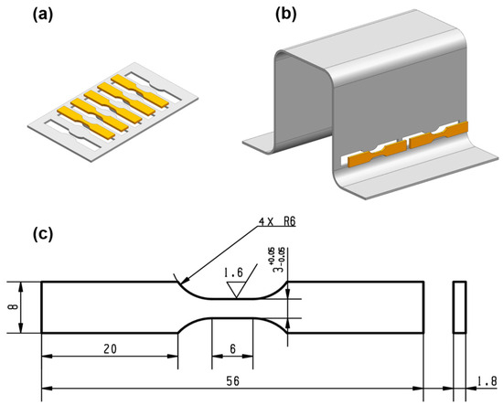
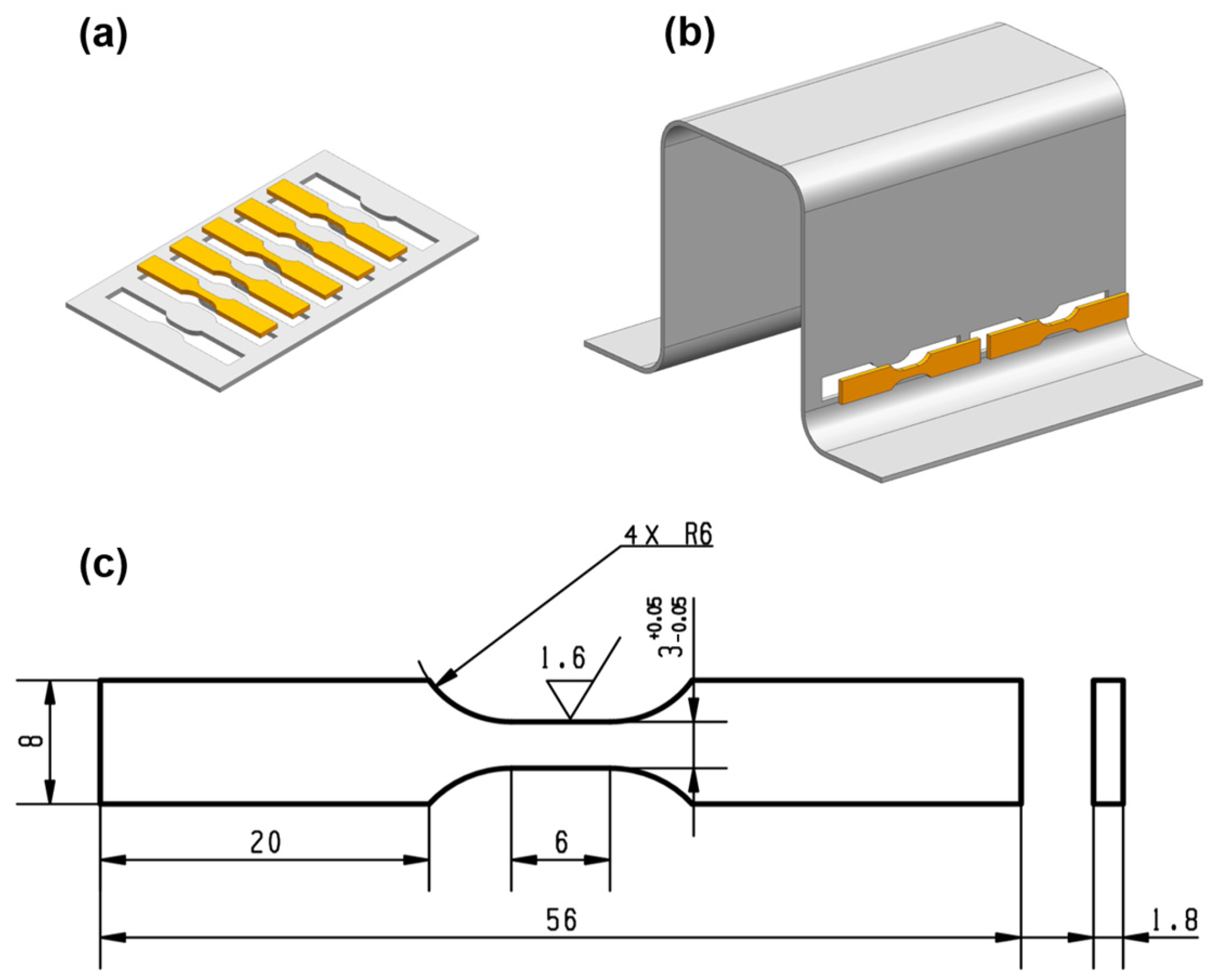
Zn-coated high-strength boron steel sheets (1.8 mm thickness) with a nominal composition (wt.%) of C 0.23, Si 0.25, Mn 1.99, and B 0.003 were used in this study. To evaluate the influence of LME cracks formed during hot stamping on mechanical and fatigue behavior, two die configurations were employed to produce specimens with distinct surface conditions. Flat specimens were hot-stamped in planar dies that imposed negligible plastic strain, thereby preventing LME formation and serving as baseline references. Hat-shaped specimens were formed in bending dies that introduced tensile stresses in the sidewalls, promoting liquid Zn penetration along grain boundaries and inducing surface LME cracking. It should be noted that while both specimen types were subjected to the same austenitization and quenching thermal cycle, the bending deformation required to induce LME cracking in hat-shaped specimens inevitably introduces forming-related residual stresses, which represent a limitation of the present experimental design and are discussed further in Section 3.3. Hot stamping was conducted under conditions representative of industrial practice. Test blanks cut from the steel sheets were austenitized at 900 ± 10 °C for 300 ± 5 s, transferred to the die within 10 s to minimize heat loss, and held in-die for 10 s. Quenching at cooling rates of 30–50 °C·s−1 ensured the formation of a martensitic microstructure at room temperature. After stamping, all mechanical test specimens were machined by wire electrical discharge machining (wire-EDM) using finish-cut parameters targeting a side-surface roughness of Ra ≈ 1.6 μm. Identical machining parameters were applied to both flat and hat-shaped specimens to ensure consistent surface conditions for comparative evaluation. Die geometries, sampling locations, and specimen dimensions for fatigue testing are illustrated in Figure 1.
Figure 1.
Schematic illustration of specimen preparation: (a) flat specimens; (b) hat-shaped specimens with sidewall cracking; (c) geometry and dimensions of mechanical test specimens. All dimensions are in millimeters; the side-surface machining roughness value Ra = 1.6 μm.
Uniaxial tensile tests were conducted on a Shimadzu AGX-V 50 kN universal testing machine (Shimadzu, Kyoto, Japan) under crosshead displacement control in accordance with GB/T 228.1-2021 [24]. A two-stage crosshead displacement rate protocol was applied: 1 mm/min up to 2% strain, increasing to 28 mm/min thereafter. At least three specimens of each type were tested to ensure statistical reliability. High-cycle fatigue tests were conducted on an MTS Bionix 370.02 servohydraulic system (MTS System, Eden Prairie, MN, USA) under fully reversed tension–compression loading (stress ratio R = −1) with a sinusoidal waveform at 20 Hz. Each test was terminated under one of two conditions: (i) complete fracture, defined as specimen separation into two parts, or (ii) survival to 107 cycles without failure, designated as a runout, indicating that the fatigue limit under the applied stress amplitude had been exceeded. Stress amplitude was systematically decreased across successive tests to establish fatigue behavior over a range of loading conditions. A total of 19 flat specimens and 20 hat-shaped specimens were tested. Stress amplitudes ranged from 846 MPa to the fatigue limit region for flat specimens, and from 810 MPa to the fatigue limit region for hat-shaped specimens. The number of specimens per stress level varied from one to three, with at least three runout data points obtained near the fatigue limit for each specimen type to ensure reliable fatigue limit determination. Stress-life (S–N) curves were constructed to quantify fatigue performance degradation induced by LME cracks, with fatigue limits and regression parameters determined through statistical analysis.
Microstructural analysis and LME crack morphology evaluation were performed on cross-sectional specimens using a JEOL JXA-8050G electron probe microanalyzer (EPMA) (JEOL, Tokyo, Japan) equipped with wavelength-dispersive spectroscopy (WDS). Sample preparation involved room-temperature mounting, mechanical polishing to 0.05 μm surface finish using Al2O3 suspension, and carbon coating to enhance conductivity and imaging quality. LME crack depth quantification was conducted through EPMA cross-sectional analysis of at least 20 cracks per specimen, with statistical analysis performed to establish mean depth values and associated standard deviations. Both EBSD analysis of polished cross-sections and post-failure fractographic examination of fatigued specimens were conducted using a Zeiss GeminiSEM 300 field-emission scanning electron microscope (FE-SEM) (Zeiss, Oberkochen, Germany) equipped with an EBSD detector. EBSD was used to characterize the microstructure, phase distribution, and grain boundary characteristics, while fractographic examination identified fracture features—including crack initiation sites, early growth zones, stable propagation zones, and final fast fracture zones—across a wide range of stress amplitudes.
3. Results and Discussion
3.1. Microstructural Features and Quasi-Static Mechanical Behavior
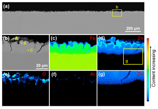
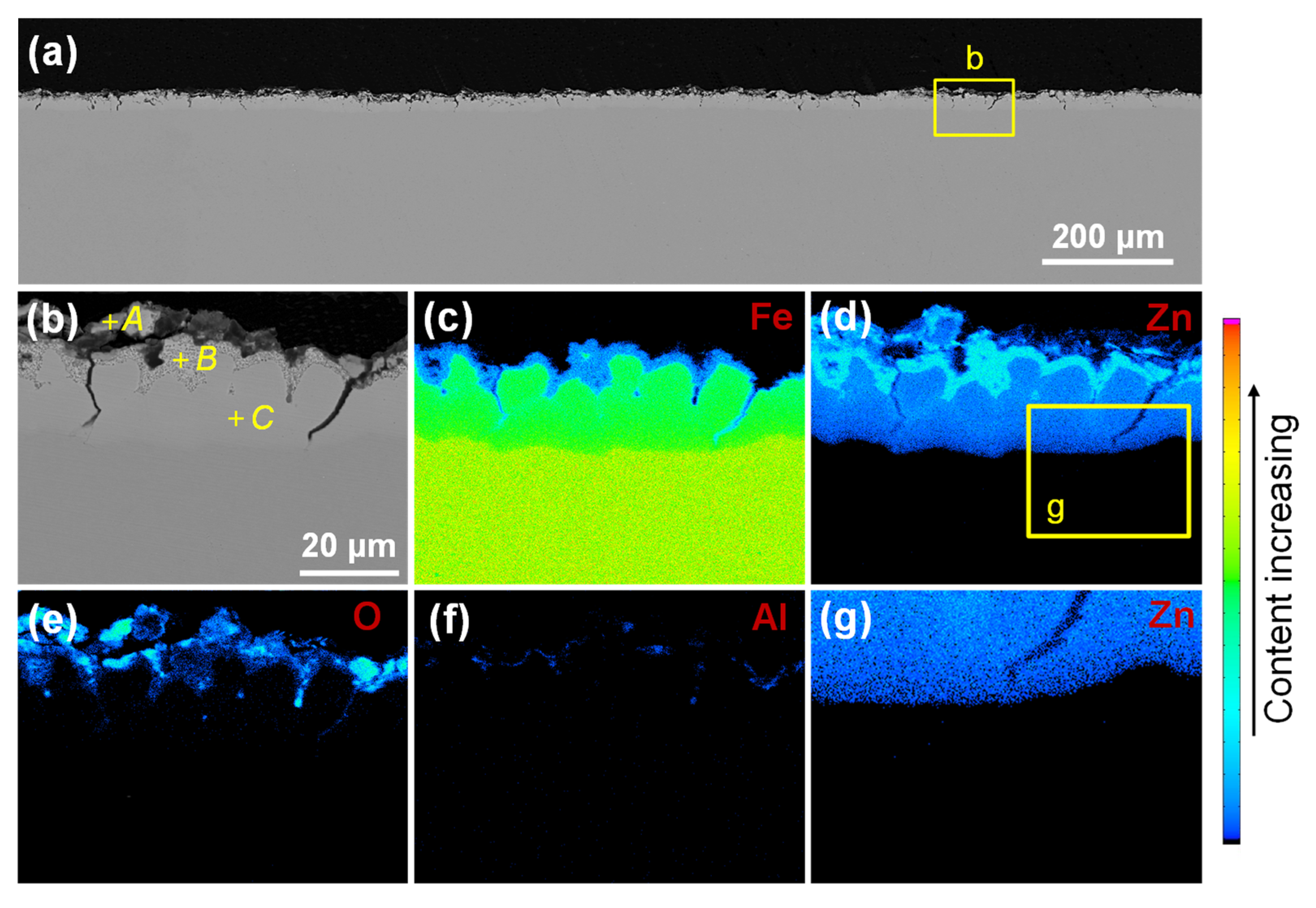
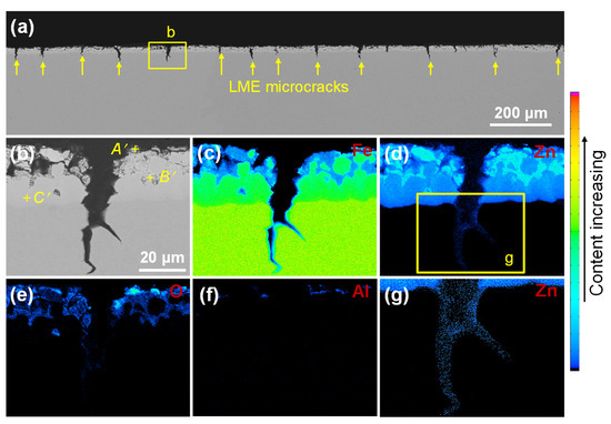
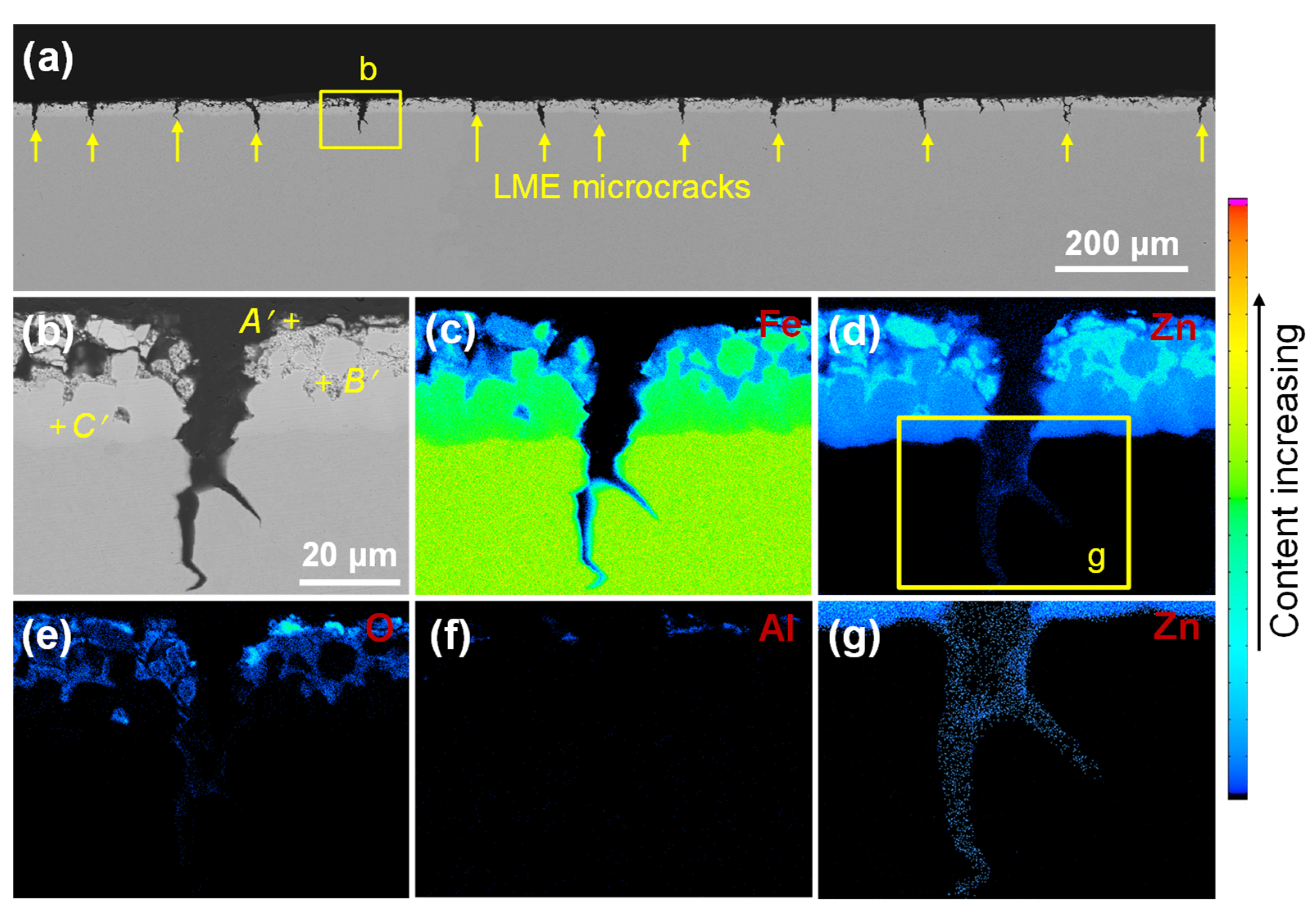
Cross-sectional microstructures and WDS elemental mapping of the Zn-coated specimens after hot stamping are shown in Figure 2 and Figure 3, with quantitative phase compositions summarized in Table 1. For each representative phase marked in Figure 2b (A, B, C) and Figure 3b (A′, B′, C′), the reported values represent the average and standard deviation of multiple measurements from Figure 2a and Figure 3a. Under the applied hot stamping conditions, both specimen types exhibited continuous and well-adhered coatings without delamination. The coating thickness, including the interdiffusion layer, was approximately 20 μm. High-magnification SEM imaging combined with chemical composition analysis (Figure 2b–f and Figure 3b–f, Table 1) revealed a multilayered structure comprising: (1) an inner α-Fe(Zn) interdiffusion layer, (2) an outer Zn-rich Γ phase (Fe3Zn10), and (3) a thin surface oxide layer primarily composed of ZnO, with minor Al2O3. Trace formation of ZnAl2O4 spinel is also possible [25].
Figure 2.
(a) Low-magnification cross-sectional morphology of the flat specimen; (b) high-magnification view of the highlighted region in (a); (c–f) WDS elemental distribution maps of Fe, Zn, O, and Al corresponding to the area in (b); (g) Zn map of the highlighted region in (d), indicating the internal crack remains confined within the coating.
Figure 3.
(a) Low-magnification cross-sectional morphology of the hat-shaped specimen; (b) high-magnification view of the highlighted region in (a); (c–f) WDS elemental distribution maps of Fe, Zn, O, and Al corresponding to the area in (b); (g) Zn map of the highlighted region in (d), revealing an LME crack within the steel substrate.
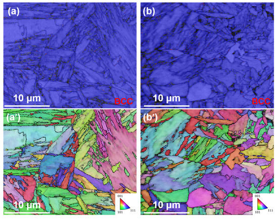
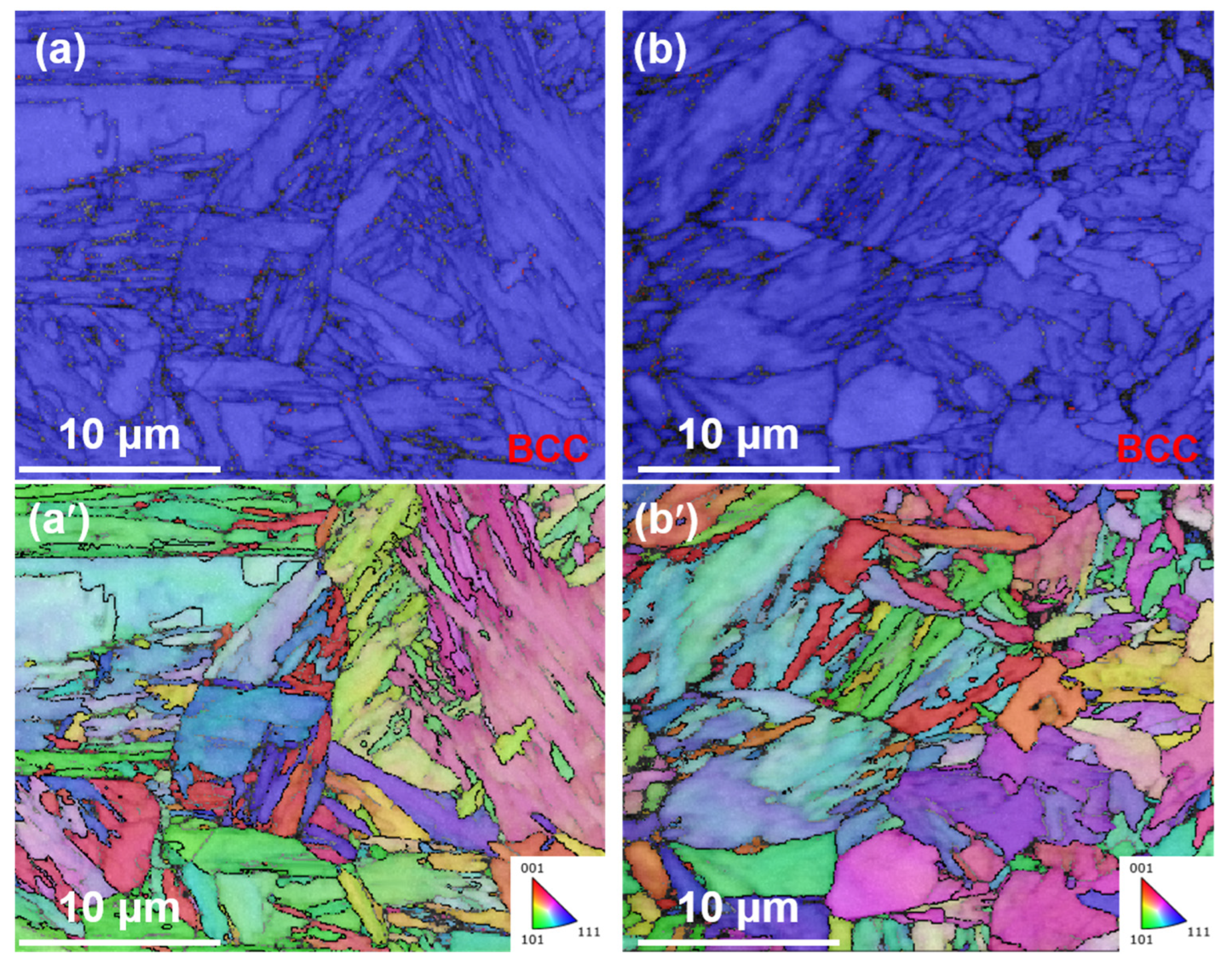
The primary difference between the two specimen types lies in their deformation histories and resulting cracks. Flat specimens experienced minimal macroscopic plastic deformation during forming, introducing neither significant tensile nor compressive stresses. Consequently, the limited cracks observed in the coating were attributed to the intrinsic brittleness of Fe–Zn intermetallics and thermal stresses generated during rapid cooling. These cracks remained confined within the α-Fe(Zn) interdiffusion layer and did not extend into the steel substrate (Figure 2g). In contrast, hat-shaped specimens exhibited numerous microcracks near the coating–substrate interface. These cracks originated within the fractured α-Fe(Zn) interdiffusion layer and propagated intergranularly along PAGBs, producing irregular dendritic morphologies characteristic of LME cracking. Statistical analysis indicates that the LME crack depth is approximately 30 ± 1.2 μm. High-resolution elemental mapping (Figure 3g) confirmed Zn enrichment along the crack paths, indicating liquid Zn penetration and stress-assisted intergranular fracture, consistent with the observations by Takahashi et al. [26]. The steel substrates of both specimen types exhibited a fully martensitic microstructure consisting of typical lath martensite, as shown in Figure 4, confirming that the identical austenitization and quenching thermal history produced equivalent substrate microstructural states in both specimen types.
Figure 4.
EBSD phase distribution maps (BCC indicates body-centered cubic martensite) and inverse pole figure (IPF) maps showing the lath martensitic microstructure in the steel substrate of the flat specimen (a,a′) and the hat-shaped specimen (b,b′).
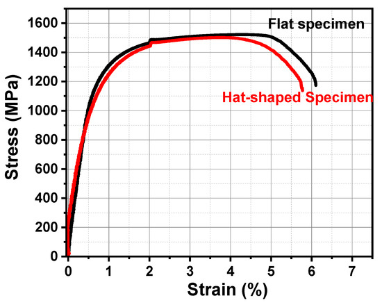
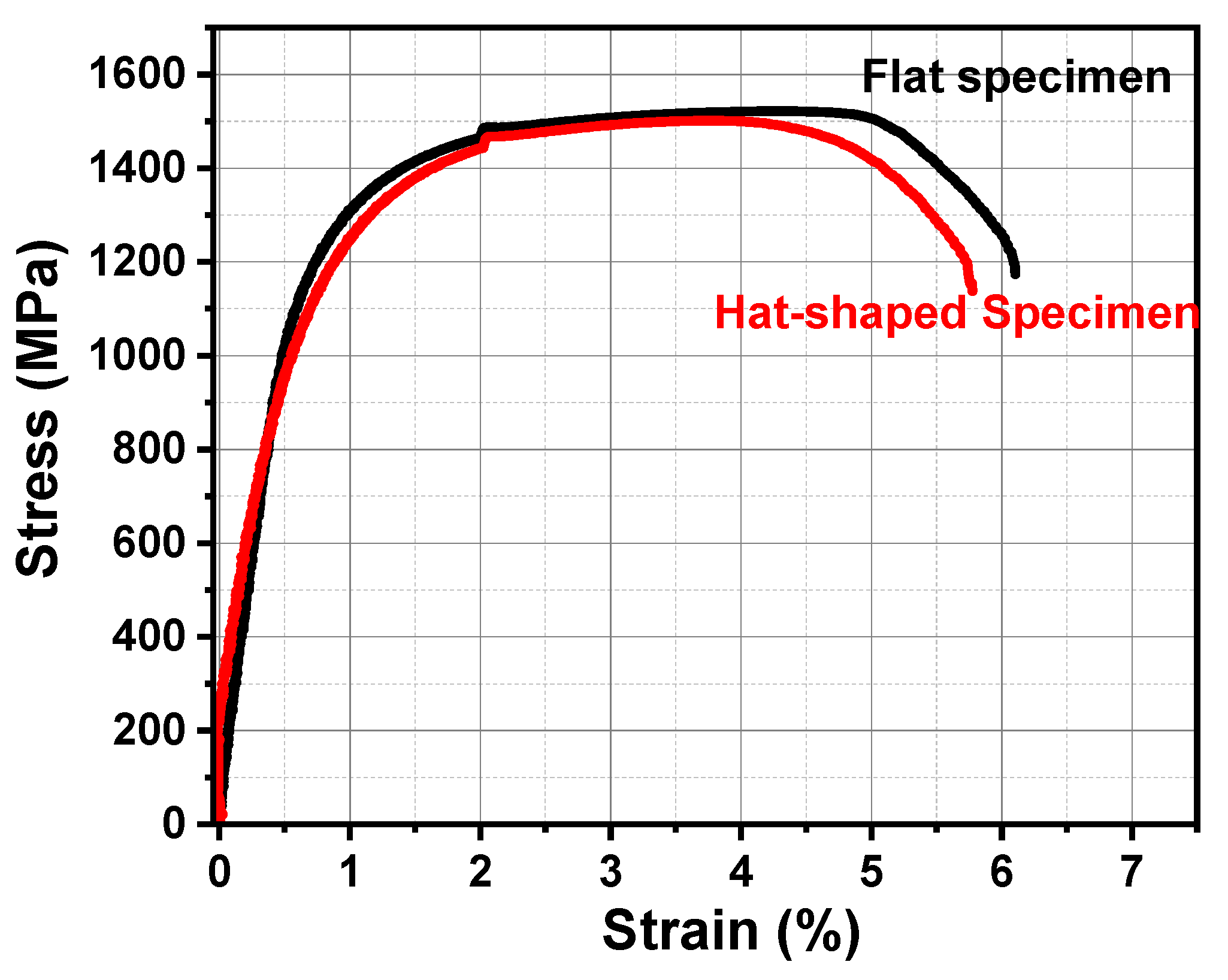
Statistical analysis of quasi-static tensile tests showed that flat specimens had a yield strength of 1490 ± 12 MPa, an ultimate tensile strength (UTS) of 1086 ± 11 MPa, and elongation of 6.00 ± 0.42%. Hat-shaped specimens with ~30 μm cracks exhibited slightly lower values, with a yield strength of 1050 ± 12 MPa, UTS of 1505 ± 18 MPa, and elongation of 5.80 ± 0.38%. These results indicate that ~30 μm LME cracks exert no practically significant effect on quasi-static mechanical properties, with reductions of ~3.3% in yield strength, ~0.9% in UTS, and ~3% in ductility. Representative engineering stress–strain curves for both specimen types are shown in Figure 5. The discontinuity observed at approximately 2% strain in the stress–strain curves reflects the prescribed increase in crosshead displacement rate at this strain level, as described in Section 2, and is an artifact of the test protocol rather than an intrinsic material response.
Figure 5.
Representative engineering tensile stress–strain curves of flat and hat-shaped specimens.
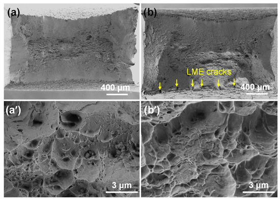
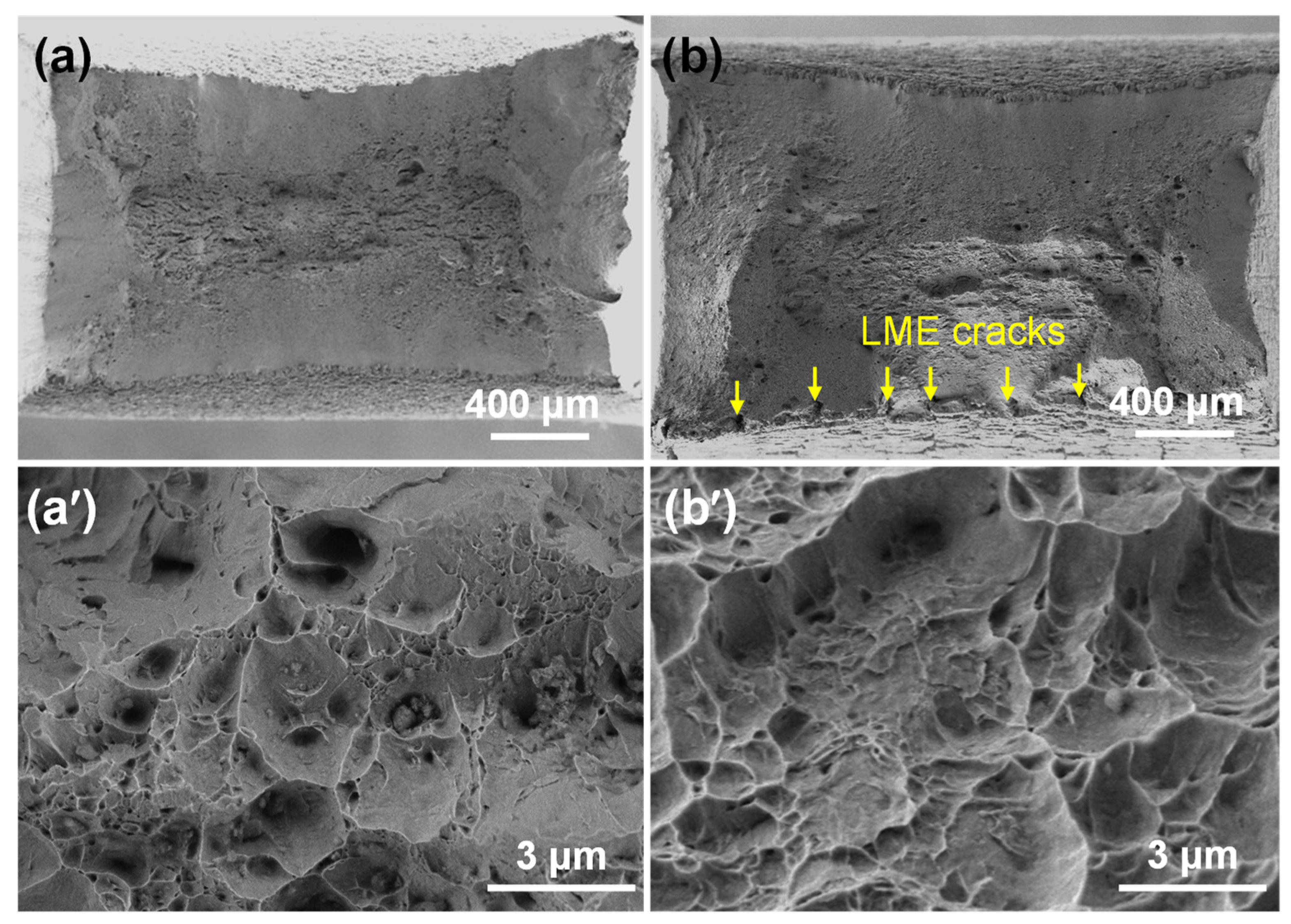
Fractographic analysis of tensile specimens (Figure 6) includes both macroscopic fracture profiles and high-magnification SEM images. Both specimen types exhibited ductile fracture characteristics, with numerous ductile dimples of similar size and morphology. Flat specimens displayed a typical plane-stress fracture profile, featuring a central ductile tearing region and peripheral shear lips, as expected for flat tensile geometries. Hat-shaped specimens also fractured in a predominantly ductile manner; however, boundaries between the central ductile zone and surrounding shear lips were less distinct. This blurring was attributed to interference from surface LME cracks. Nevertheless, primary fracture still originated from the central region, indicating that LME cracks did not serve as dominant crack initiation sites. Instead, they may have locally accelerated void coalescence during necking, leading to the minor reduction in total elongation. While LME cracks in hat-shaped specimens slightly reduced ductility, their effect on strength and fracture mechanism under quasi-static loading was minimal.
Figure 6.
Macroscopic fracture surfaces and corresponding microscopic morphologies of specimens after tensile testing: (a,a′) flat specimen and (b,b′) hat-shaped specimen.
The close agreement in quasi-static mechanical properties between the two specimen types provides indirect evidence that the substrate microstructural state and bulk mechanical condition are essentially equivalent. This equivalence supports the interpretation that differences in fatigue performance, discussed in the following sections, are predominantly attributable to the presence of surface LME cracks rather than to differences in substrate microstructure or bulk residual stress state. Nevertheless, given their morphology and intergranular penetration, such pre-existing cracks may act as preferential fatigue initiation sites, potentially exerting a much stronger influence on high-cycle fatigue performance.
3.2. High-Cycle Fatigue Performance and Fractographic Characteristics
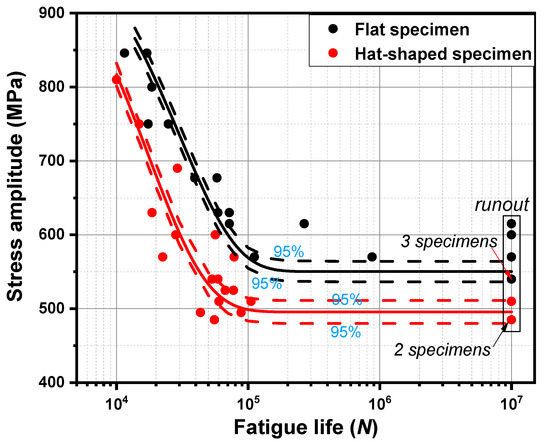
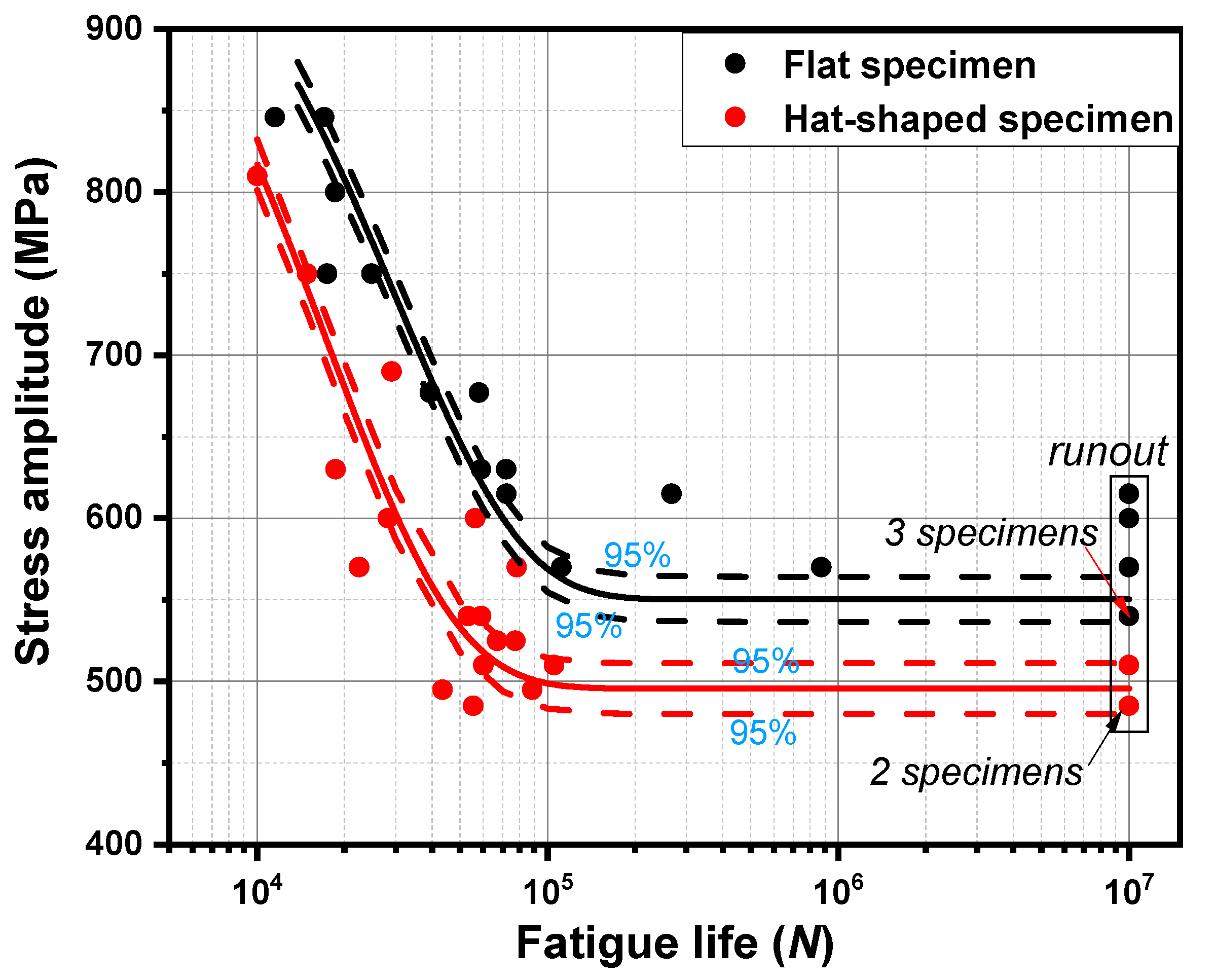
The resulting S–N curves are presented in Figure 7. Both specimen types exhibited a nonlinear decline in fatigue life with increasing stress amplitude [27]. Across the entire stress range, hat-shaped specimens consistently exhibited shorter fatigue lives, indicating that LME cracks significantly reduce fatigue resistance. The complete fatigue test dataset for both specimen types is summarized in Table 2. Given that the number of specimens per stress level in the present study (2–3 specimens) is insufficient to support statistically robust probability S–N curve fitting (e.g., P-S-N curves at 10%, 50%, and 90% probability levels, which typically require substantially larger sample sizes), nonlinear regression was applied to fit the experimental data. The 95% confidence bands of the regression fits are included in Figure 7 to provide a visual representation of the fitting uncertainty associated with the observed data scatter. The regression yielded the following empirical relationships:
where is the stress amplitude (MPa) and N is the fatigue life (cycles). The goodness-of-fit is indicated by the coefficient of determination (R2). The fatigue limits at 107 cycles were 550 MPa for flat specimens and 490 MPa for hat-shaped specimens, corresponding to a 10.9% reduction attributable to the presence of LME cracks.
Figure 7.
High-cycle fatigue stress-life (S–N) curves of flat and hat-shaped specimens. Dashed lines represent 95% confidence bands of the regression fit.
Table 2.
Tension–compression fatigue test data of Zn-coated press-hardened steel specimens.
While these macroscopic S–N trends quantify overall performance degradation, they do not indicate whether crack initiation originates from pre-existing LME defects, intrinsic substrate flaws, or a combination of both. Data acquisition in the intermediate life regime (105–107 cycles) proved particularly challenging, especially for hat-shaped specimens, which tended either to fail rapidly or to survive to runout. The slightly lower R2 value for hat-shaped specimens (0.89 vs. 0.92) reflects the pronounced scatter in fatigue life inherent to this specimen type, which arises from the stochastic nature of LME crack activation as fatigue initiation sites rather than from test methodology limitations. This scatter is consistent with the highly dispersed fatigue data previously reported for Zn-coated 22MnB5 steel with surface LME cracks of varying depths [21,22], suggesting that such pronounced scatter is a characteristic feature of LME-affected materials in this class.
3.2.1. Fracture Features of Flat Specimens
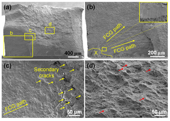
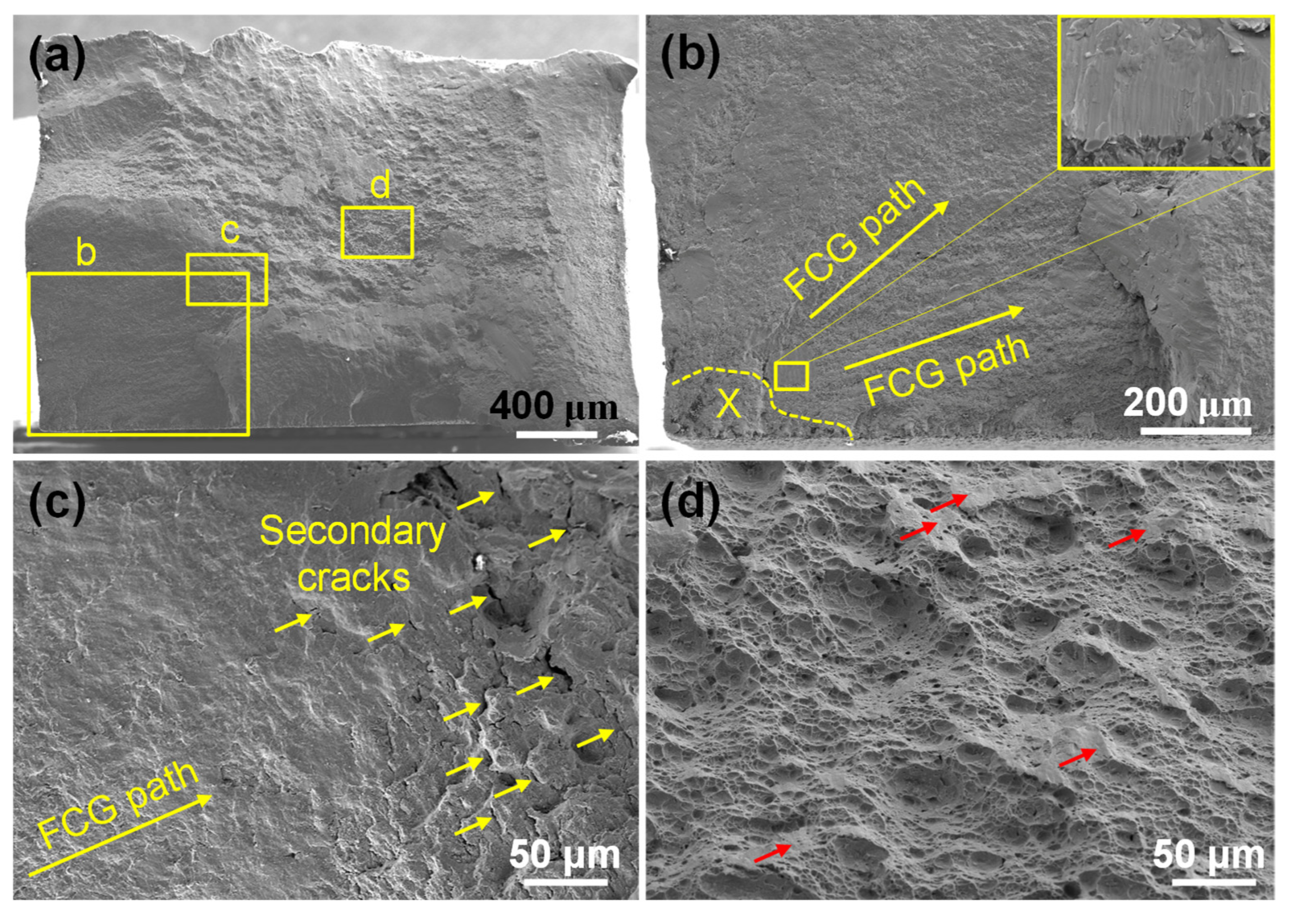
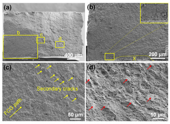
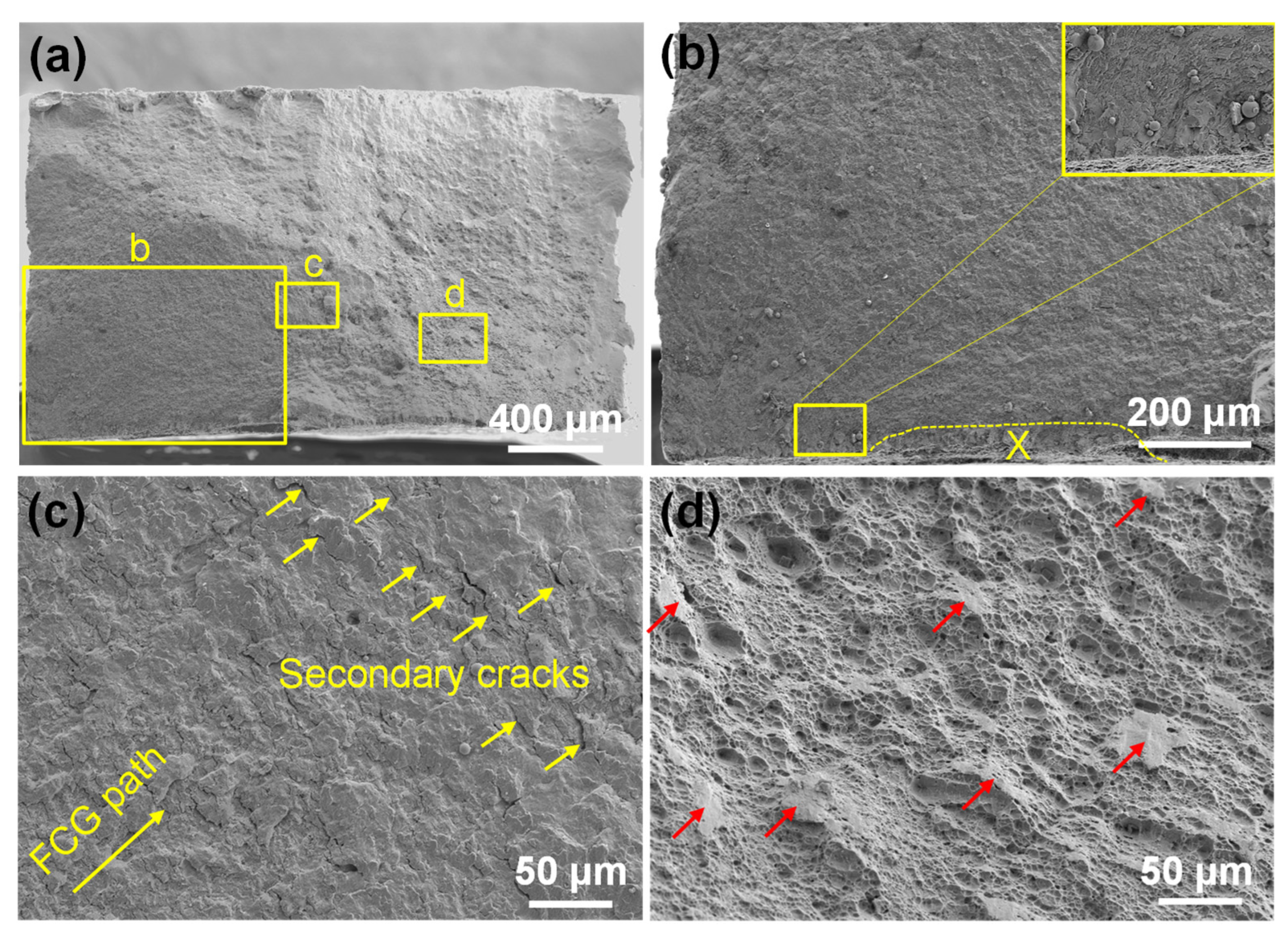
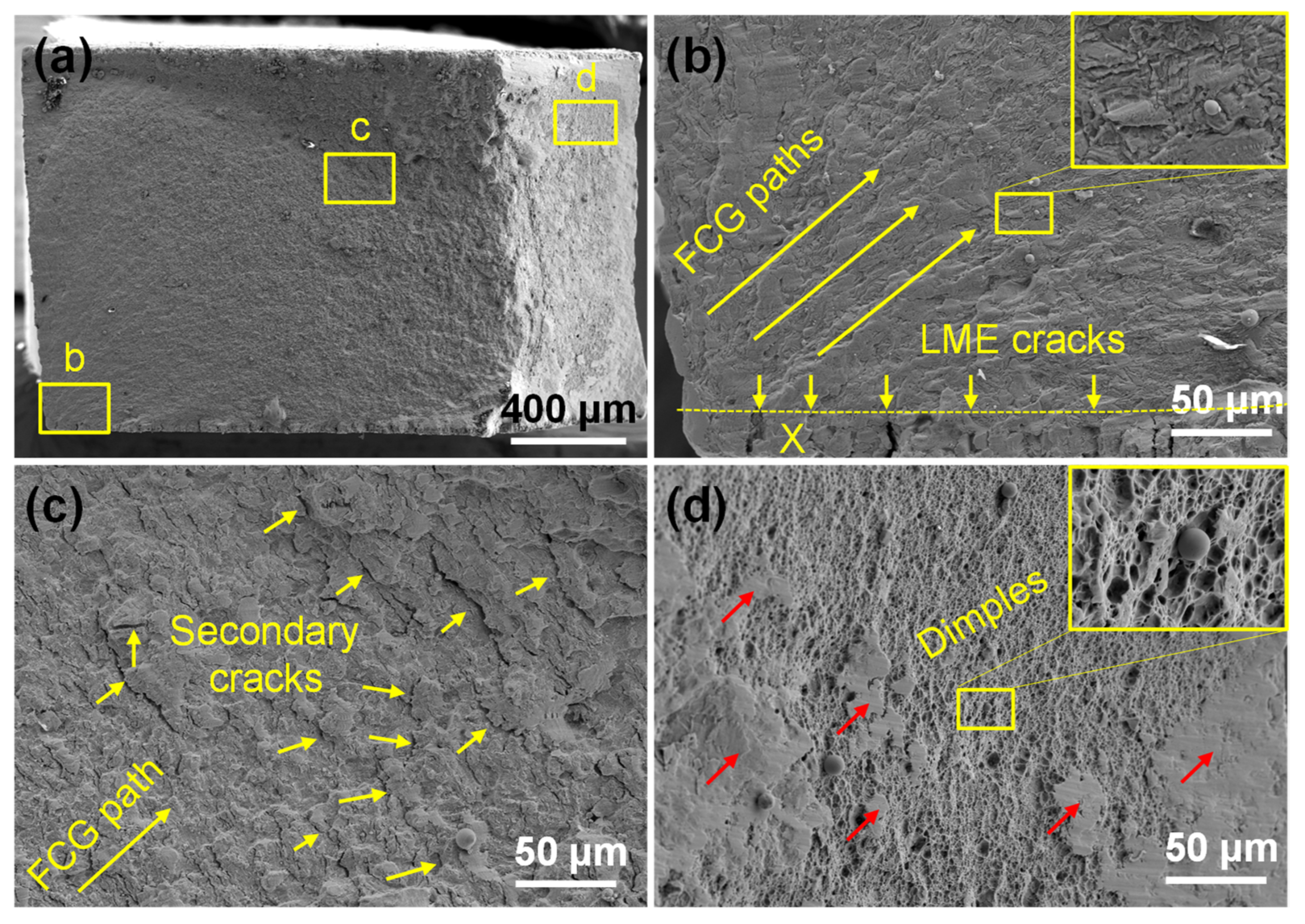
Figure 8 illustrates the typical fatigue fracture morphology of flat specimens subjected to high-stress cyclic loading (846 MPa). The macroscopic fracture surface (Figure 8a) exhibits distinct surface topography that clearly delineate zones of fatigue crack initiation, stable crack propagation, and final fast fracture. This progression effectively captures the full evolution of fatigue damage under high-stress conditions. As shown in Figure 8b, reverse tracing of fatigue striations identifies a crack initiation site located at the intersection of the specimen surface and edge—a region highly susceptible to stress concentration (marked with an X in the lower-left dashed box). Severe stress gradients under high-stress loading likely accelerate local stress accumulation around inherent material defects such as surface machining marks or fine inclusions. Crack propagation follows these fatigue crack growth (FCG) paths. Near the boundary between the crack propagation and final fast fracture zones (Figure 8c), the fracture surface exhibits a terraced morphology with locally observed secondary cracks oriented nearly perpendicular to the main crack path. According to the mixed blunting/re-sharpening and micro-void coalescence mechanism proposed by Li et al. [28], such secondary cracks form ahead of the main crack front through micro-void nucleation and coalescence. Their presence accelerates unstable crack advance, thereby reducing fatigue life. The final fast fracture zone is characterized by typical ductile features. The magnified view (Figure 8d) reveals ductile dimples with significant depth variations and ridge patterns characteristic of ductile fracture. Localized crack face contact marks are visible (indicated by red arrows), resulting from frictional contact between opposing crack faces during the compressive phase of cyclic loading—a phenomenon commonly observed in high-stress fatigue.
Figure 8.
Fatigue fracture morphologies of a flat specimen tested at a stress amplitude of 846 MPa (N = 17,053 cycles): (a) overview of the fracture surface; (b–d) higher-magnification images of the regions marked in (a), showing (b) the fatigue crack initiation site (marked X) and subsequent propagation zone, (c) secondary cracks in the transition region between crack propagation and final fast fracture, and (d) ductile dimples in the final fracture zone with localized crack face contact marks (red arrows) resulting from compressive loading phases.
Figure 9 presents fracture morphologies of flat specimens tested under stress amplitudes (677 MPa, 630 MPa) and near the fatigue limit (570 MPa). Compared to the high-stress condition (846 MPa), fracture surfaces at these lower stress levels are notably flatter, with more distinct boundaries separating the fatigue crack initiation, propagation, and final fracture zones. This enhanced clarity facilitates easier identification of crack origin locations. Figure 9a,b demonstrate that cracks still predominantly initiate at surface–edge intersections (marked with X). During cyclic loading, crack tips undergo repeated blunting from plastic deformation during tensile phases, followed by re-sharpening during compressive phases as stresses reverse. This cyclic blunting and sharpening persists over multiple cycles, driving gradual crack propagation into the specimen interior. Initiation zones display rough morphologies with river markings oriented along the crack growth direction. When the local stress intensity exceeds a critical value, secondary cracks form at the boundary between propagation and final fast fracture, marking the transition from stable to unstable fracture. At the near-threshold stress amplitude of 570 MPa (Figure 9c,d), crack initiation shifts from surface–edge intersections to subsurface regions close to the edge (marked X in Figure 9d). This transition indicates that under low stress, fatigue initiation becomes more sensitive to microstructural heterogeneities rather than surface features. Crack growth behavior still exhibits radial divergence with fatigue striations perpendicular to the crack growth direction observed within the propagation zone (inset in Figure 9d). Notably, final fast fracture zones (insets in Figure 9a–c) show fewer ductile dimples with decreasing cyclic stress amplitude. Nevertheless, across all stress levels, flat specimens consistently display predominantly ductile fracture features in the final fracture zone, as evidenced by ductile dimples in the magnified images.
Figure 9.
Fatigue fracture morphologies of flat specimens tested at stress amplitudes of (a) 677 MPa (N = 58,004 cycles), (b) 630 MPa (N = 59,008 cycles), and (c) 570 MPa (N = 111,604 cycles). Insets in (a–c) show magnified views of the final fast fracture zones. (d) Enlarged view of the highlighted region in (c), illustrating the fatigue crack initiation zone, radial crack growth paths within the crack propagation zone, and localized fatigue striations (inset). The “X” marks in the images indicate the crack initiation sites.
3.2.2. Fracture Features of Hat-Shaped Specimens
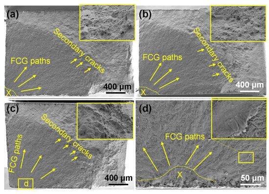
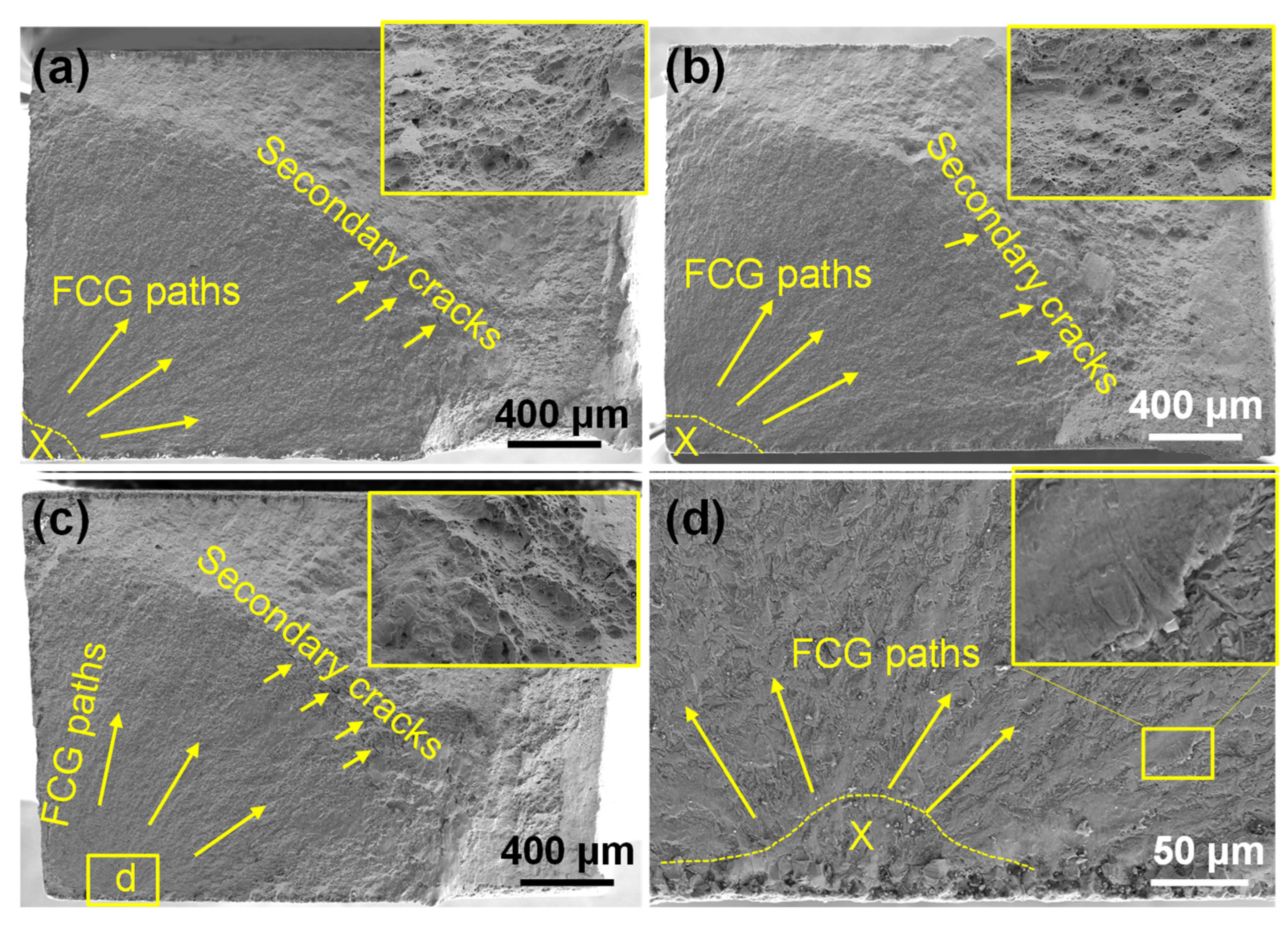
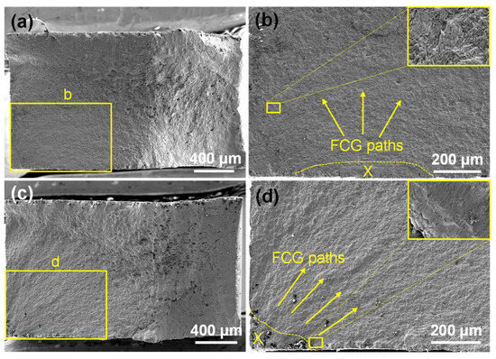
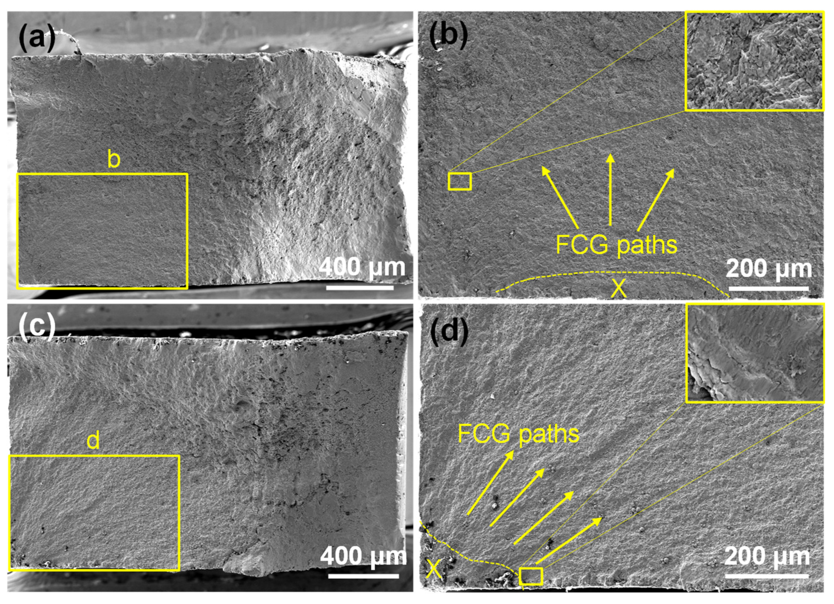
Hat-shaped specimens experienced substantial tensile stress during hot stamping, resulting in the formation of LME cracks on their surfaces. These pre-existing microcracks significantly complicate subsequent fatigue crack initiation and propagation. Figure 10a shows the macroscopic fracture morphology of hat-shaped specimens subjected to relatively high cyclic stress (810 MPa). The fracture surface exhibits the characteristic three-zone fatigue structure: crack initiation, crack propagation, and final fast fracture zones, with an overall fracture pattern comparable to that of flat specimens. As shown in Figure 10b, cracks initiated near the central region of the specimen’s lower surface edge (marked X), with fatigue striations visible throughout the surrounding propagation zone. The propagation zone (Figure 10c) contains multiple secondary cracks oriented nearly perpendicular to the main crack, reflecting intensified damage accumulation during stable growth. The final fast fracture zone (Figure 10d) exhibits numerous ductile dimples with minor crack face contact marks (red arrows), consistent with ductile fracture characteristics observed in flat specimens. Notably, at this stress amplitude of 810 MPa, no distinct LME crack features were detected on the fracture surface. Figure 11 presents fracture morphologies of hat-shaped specimens under stress amplitudes of 750 MPa and 690 MPa. The overall fracture mode remains consistent with that observed at 810 MPa, showing a clear three-zone structure. Compared to the high stress amplitude of 810 MPa, the crack propagation zone is substantially enlarged at 750 MPa and 690 MPa. Crack initiation sites consistently appear on the specimen surface, although their locations varied spatially (marked with X in Figure 11b,d). Similarly, no distinct LME crack features were detected on fracture surfaces under these conditions.
Figure 10.
(a) Macroscopic fatigue fracture morphology of a hat-shaped specimen tested at a stress amplitude of 810 MPa (N = 10,025 cycles); (b–d) enlarged views of the regions marked in (a), showing (b) the fatigue crack initiation and propagation zones (the “X” marks in this image indicate the crack initiation site), (c) secondary cracks within the transition region between crack propagation and final fast fracture, and (d) ductile dimples in the final fracture zone interspersed with minor crack face contact marks (indicated by red arrows).
Figure 11.
Macroscopic fatigue fracture morphologies of hat-shaped specimens tested at stress amplitudes of 750 MPa (N = 14,855 cycles) (a) and 690 MPa (N = 29,033 cycles) (c). (b) and (d) are enlarged views of the highlighted regions in (a) and (c), respectively, showing the corresponding fatigue crack initiation and propagation zones. The “X” marks in (b,d) indicate the crack initiation sites. Insets in (b,d) provide further magnified fatigue striations.
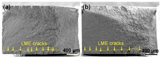
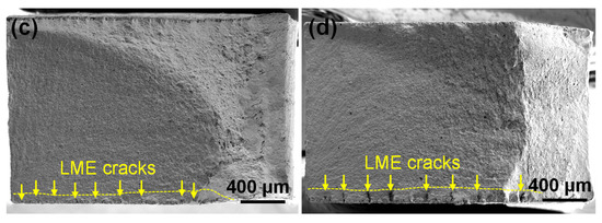
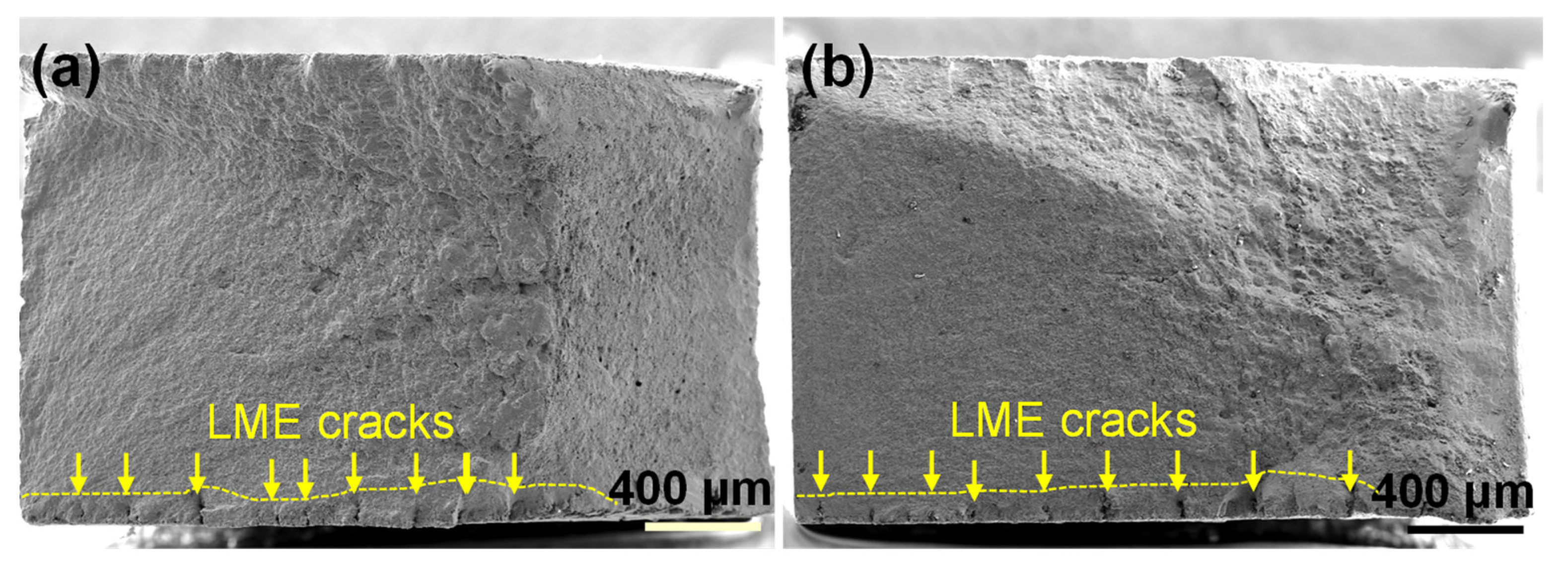
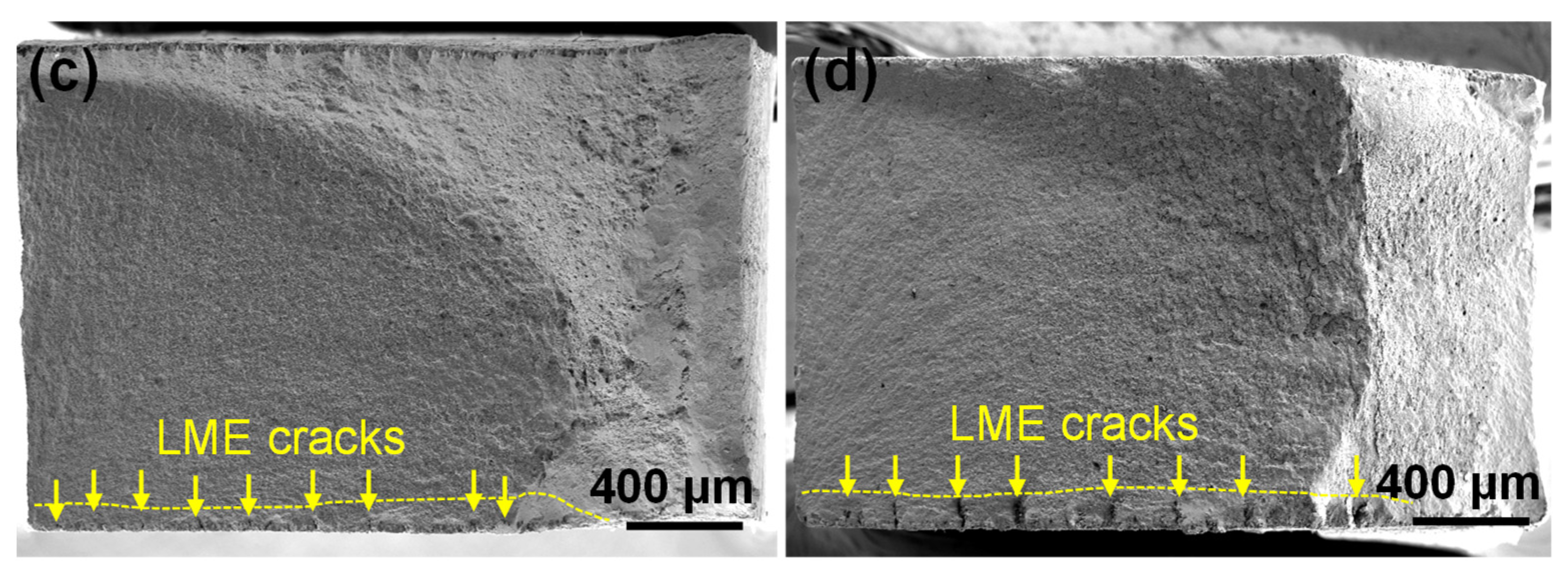
Figure 12 and Figure 13 show the fracture morphologies of hat-shaped specimens tested under moderate-to-low stress amplitudes (630, 600, 570, and 525 MPa in Figure 12; 485 MPa in Figure 13). In contrast to the high-stress regime (≥690 MPa), a distinct and consistent feature emerges: LME cracks are clearly visible in the crack initiation zone below the yellow dashed line indicated in the figures, corresponding to the lower edge of the fracture surface, with the adjacent substrate displaying well-developed ductile dimples. These surface-connected cracks exhibit several diagnostic features distinguishing them from mechanically initiated fatigue cracks: (i) they are confined to the Zn-affected surface region with characteristic spacing of ~100–200 μm, consistent with the morphological features observed in Figure 3; and (ii) their location distributed continuously along the lower edge of the fracture surface correlates with regions experiencing tensile stress during hot stamping. These LME cracks act as dominant initiation sites, directly driving fatigue failure. Taking the 485 MPa specimen as a representative example, the macroscopic fracture surface (Figure 13a) still displays the characteristic three-zone structure; however, the crack initiation zone along the lower edge is markedly enlarged. Higher-magnification imaging (Figure 13b) reveals crack initiation at the lower surface edge, with fatigue striations perpendicular to the crack growth direction visible in the propagation zone (inset). The direct spatial continuity between LME cracks and the subsequent fatigue propagation zone, combined with the absence of alternative initiation sites in this region, confirms that fatigue cracking originated from these pre-existing LME fissures rather than from bulk material defects. The aligned LME cracks in this region serve as preferential crack nucleation sites during fatigue initiation. The propagation zone (Figure 13c) contains multiple secondary cracks at varying orientations to the primary crack path, indicating a multi-site crack initiation tendency. The interaction of numerous initiation sites produces a complex local stress environment, in sharp contrast to the predominantly single-path propagation observed in flat specimens (Figure 8c and Figure 9a–c). The final fast fracture zone (Figure 13d) exhibits shallow ductile dimples (inset) with more extensive crack face contact marks (red arrows) compared to specimens tested at higher stress amplitudes.
Figure 12.
Macroscopic fatigue fracture morphologies of hat-shaped specimens subjected to stress amplitudes of (a) 630 MPa (N = 18,643 cycles), (b) 600 MPa (N = 56,352 cycles), (c) 570 MPa (N = 22,464 cycles), and (d) 525 MPa (N = 77,403 cycles). In all cases, fracture initiation occurred along the lower edge of the specimen surface, where LME cracks were observed.
Figure 13.
(a) Macroscopic fatigue fracture surface of a hat-shaped specimen tested at a stress amplitude of 485 MPa (N = 55,455 cycles). (b–d) Enlarged views of the marked regions in (a): (b) crack initiation and propagation zone (the “X” mark in this image indicates the crack initiation site), with enlarged striations shown in the inset; (c) randomly oriented secondary cracks in the propagation zone; and (d) final fracture zone exhibiting both dimples (enlarged in inset) and extensive crack face contact marks (red arrows).
Overall, fracture analysis of hat-shaped specimens under moderate-to-low stress amplitudes (≤630 MPa) demonstrates that fatigue cracks predominantly initiate from LME cracks. This multi-site initiation tendency lowers the crack initiation threshold, shortens initiation life, and markedly accelerates fatigue degradation. By contrast, at higher stress amplitudes, initiation is dominated by intrinsic substrate defects, highlighting a stress-dependent transition of the governing fatigue mechanism. Across all stress amplitudes, the fracture process exhibits a consistent hierarchical character: brittle intergranular LME crack initiation, mixed-mode fatigue propagation, and characteristically ductile final fracture—a sequence that distinguishes LME-affected fatigue failure from conventional surface-defect-induced failure in high-strength steels.
3.3. Fracture Mechanics Analysis of LME Crack-Induced Fatigue Degradation
Building on the stress-dependent transition established in Section 3.2.2, this section examines the fracture mechanic implications of LME crack behavior. While fractographic evidence consistently supports this stress-dependent transition, the interpretation requires the consideration of a potential confounding factor. As noted in Section 2, hat-shaped specimens carry forming-induced residual stresses that could not be independently quantified in the present study, representing a limitation of the experimental design. Nevertheless, two lines of evidence support the interpretation that LME cracks are the predominant factor governing the observed fatigue limit reduction. First, both specimen types share identical thermal histories and equivalent martensitic microstructures and quasi-static mechanical properties, as demonstrated in Section 3.1. Second, the systematic stress-dependent transition in crack initiation mechanism—whereby LME crack influence is suppressed at high stress amplitudes but dominates at moderate-to-low amplitudes—exhibits a regularity inconsistent with the spatially diffuse and stress-amplitude-independent nature of residual stress effects.
To quantitatively characterize the scale effects of LME cracks on fatigue behavior, the El Haddad model was employed [29]. This model, grounded in LEFM, introduces an El-Haddad parameter (critical crack length) l0 to uniformly describe the fatigue behavior of both short and long cracks, with the physical significance of defining the transition boundary between short and long cracks. When the actual crack length l < l0, cracks exhibit short crack characteristics with propagation behavior primarily controlled by microstructural features; when l > l0, they exhibit long crack characteristics with propagation behavior mainly dominated by macroscopic stress fields. The calculation formula for characteristic length is
where , and Y represent the fatigue limit stress, fatigue crack propagation threshold stress intensity factor, and shape factor, respectively.
In the absence of direct experimental measurements of for the present Zn-coated boron steel, parameters from Al–Si-coated 22MnB5 reported by Parareda et al. [20] were adopted as a preliminary estimate, based on the following rationale. First, reflects the crack propagation threshold of the steel substrate rather than the coating, and both materials share the same 22MnB5 substrate composition. Second, they demonstrated that this value yielded good agreement between predicted and experimental fatigue limits for Zn-coated 22MnB5 specimens in which coating cracks were confined within the coating layer and did not penetrate into the substrate—a condition fundamentally different from the LME substrate cracking observed in the present study. This distinction is important and is discussed further below. Accordingly, = 5.80 and Y = 1.13 were adopted, and this approach is acknowledged to carry uncertainty associated with potential differences in coating chemistry and microstructural state. Combined with the experimentally measured fatigue limit of the flat specimens ( = 550 MPa), these values yield a characteristic length of l0 ≈ 27.72 μm. The observed LME cracks (~30 μm) are marginally larger than this critical length, placing them at the short-to-long crack transition boundary. At this scale, crack behavior exhibits characteristics of both regimes: while the applied stress field begins to dominate (long-crack tendency), microstructural effects remain significant (short-crack influence). This transitional nature introduces inherent complexity that conventional single-regime fracture mechanics models are not designed to capture.
Conventional LEFM threshold analysis—typically applicable to well-defined long cracks—was further employed as a preliminary assessment to estimate the critical stress amplitude () required for fatigue crack growth [30,31]. For surface semi-elliptical cracks, is given by
where l represents the LME crack length. For the ~30 μm LME cracks in hat-shaped specimens, the estimated is approximately 528 MPa—notably higher than the experimentally measured fatigue limit of 490 MPa. Applying the same analysis to the deeper LME cracks (~80 μm) reported in the literature [21,22], which fully reside within the long-crack regime, yields ≈ 323 MPa, yet the corresponding experimental fatigue limit was reported as only 170 MPa—a discrepancy even more pronounced than in the present case. It is important to note that in the work of Parareda et al. [20], where the same was applied to Zn-coated 22MnB5 specimens without LME substrate cracking, the LEFM predictions agreed well with experimental results. The systematic overestimation observed in the present study—and further amplified for deeper LME cracks—therefore cannot be attributed solely to parameter uncertainty. Rather, it reflects the inherent limitations of applying conventional single-crack LEFM models to LME-affected materials, and points to the operation of additional degradation mechanisms not captured by standard fracture mechanics frameworks.
Based on the present fractographic observations and the existing literature, two qualitative factors are proposed to account for this discrepancy. It should be emphasized from the outset that, in the absence of three-dimensional crack network characterization or dedicated numerical simulation of crack interaction, these factors represent interpretations that are consistent with the observed fracture morphology and established physical principles, rather than conclusions directly demonstrated by the present data. Their individual quantitative contributions remain to be established in future work.
The first factor concerns high crack density and morphological complexity. LME cracks develop at high surface densities (~100–200 μm spacing, Figure 3), providing a continuous array of pre-existing initiation sites rather than the single dominant defect assumed by conventional LEFM. Unlike isolated mechanical cracks, LME cracks exhibit irregular morphologies characterized by branching, deflection, and variable depths [32], which may extend their effective stress concentration beyond what is captured by the apparent crack depth alone. Fractographically, the multi-directional secondary cracks observed in the propagation zone (Figure 13c) are consistent with simultaneous activation of multiple neighboring initiation sites, producing a more complex damage accumulation pathway than the predominantly single-path propagation observed in flat specimens (Figure 8c and Figure 9a–c). Whether the spatial proximity of these cracks leads to measurable stress field interaction—as would be expected from the crack spacings observed relative to crack depths—cannot be confirmed without numerical modeling, and is identified as an important question for future work.
The second factor concerns chemically assisted grain boundary weakening, for which the present study provides more direct experimental support. LME cracks propagate intergranularly along PAGBs, as confirmed by the dendritic crack morphology and Zn enrichment along crack paths shown in Figure 3g. PAGBs offer inherently lower resistance to crack growth due to weaker slip system coupling [17,18], and liquid Zn infiltration along these boundaries has been shown by first-principles calculations to reduce grain boundary cohesive strength [33,34]. The resulting atomically sharp intergranular pre-cracks—chemically embrittled at the grain boundary level—are fundamentally different from mechanically initiated surface notches: they lower the effective threshold for fatigue crack propagation, particularly in the early growth stage when crack-tip plastic zone size is comparable to or smaller than the grain boundary embrittlement zone. This effect is not represented by conventional threshold stress intensity parameters derived from mechanically initiated cracks in unaffected material, and provides a physically grounded explanation for why LEFM systematically overestimates the fatigue threshold stress in LME-affected specimens.
Rigorous quantification of both factors would require three-dimensional crack network characterization, local stress field measurements, dedicated multi-crack interaction modeling, and residual stress characterization by X-ray diffraction—all of which are beyond the scope of the present study and are identified as important directions for future work. Nevertheless, the systematic discrepancy between LEFM predictions and experimental fatigue limits—observed consistently across crack depths from ~30 μm (present study) to ~80 μm (literature [21,22])—provides strong empirical evidence that conventional fracture mechanics frameworks are inadequate for LME-affected hot-stamped steels.
4. Conclusions
Two types of Zn-coated high-strength boron steel specimens were fabricated using different hot stamping die configurations to obtain surfaces either free of LME cracks (flat) or containing ~30 μm deep LME cracks (hat-shaped). The effects of these cracks on mechanical and fatigue behavior were systematically evaluated. The main conclusions are:
1. Quasi-static mechanical properties were largely unaffected by ~30 μm LME cracks. Flat specimens exhibited a yield strength of 1086 MPa, UTS of 1518 MPa, and elongation of 6.00%, while hat-shaped specimens showed slightly lower values of 1050 MPa, 1505 MPa, and 5.80%, respectively. Similar elastic responses and ductile dimple fracture morphologies indicate that these LME cracks do not alter the fundamental deformation mechanisms under quasi-static uniaxial loading.
2. High-cycle fatigue performance was substantially degraded, with the fatigue limit reduced from 550 MPa to 490 MPa (10.9% degradation). A critical stress-dependent transition governs failure mechanisms: above 690 MPa, fatigue initiation occurs primarily at intrinsic substrate defects, while below 630 MPa, LME cracks dominate as preferential initiation sites. This transition promotes a multi-site crack initiation tendency and accelerates early crack propagation, directly reducing fatigue life.
3. Conventional fracture mechanics models show significant limitations when applied to LME-affected materials. The El Haddad model positioned the ~30 μm LME cracks at the short-to-long crack transition boundary (l ≈ l0), while preliminary LEFM threshold analysis systematically overestimated the fatigue threshold stress. This overestimation is qualitatively attributed to two factors: the high surface density and morphological complexity of LME crack networks and chemically assisted grain boundary weakening induced by liquid Zn infiltration—the latter is supported by direct fractographic and compositional evidence in the present study. The rigorous quantification of both factors through three-dimensional characterization and numerical modeling remains an important direction for future work.
In conclusion, this study demonstrates that although ~30 μm deep LME cracks have little effect on quasi-static strength, they markedly reduce high-cycle fatigue resistance through stress-dependent crack initiation mechanisms. The identified limitations of conventional single-crack fracture mechanics frameworks for LME-affected materials motivate the development of more physically grounded fatigue life prediction approaches for Zn-coated hot-stamped high-strength steels.
Author Contributions
Data curation, S.F. and N.T.; formal analysis, S.F., N.T., J.Z., X.W., P.B. and H.Z.; investigation, S.F., N.T., J.Z., X.W., P.B. and H.Z.; validation, N.T. and J.Z.; writing—original draft, S.F. and N.T.; visualization, S.F., N.T. and H.Z.; conceptualization, H.Z.; funding acquisition, H.Z.; project administration, H.Z.; supervision, H.Z.; writing—review and editing, H.Z. All authors have read and agreed to the published version of the manuscript.
Funding
This research was funded by the Advanced Materials-National Science and Technology Major Project, grant number 2025ZD0611100.
Data Availability Statement
The data presented in this study are available on request from the corresponding authors due to confidentiality agreements with the industrial partner.
Conflicts of Interest
Authors Ning Tan, Jianyu Zhang and Xiaodeng Wang were employed by the company Automobile Steel Research Institute, R&D Center of Baoshan Iron & Steel Co., Ltd. Author Ping Bao was employed by the company Baosteel Automotive Steel Sales Department, Baoshan Iron & Steel Co., Ltd. The remaining authors declare that the research was conducted in the absence of any commercial or financial relationships that could be construed as a potential conflict of interest.
References
- Zhou, B.Y.; He, L.Q.; Zhang, S.J.; Wang, R.; Zhang, L.W.; Li, M.L.; Liu, Y.; Zhang, S.J.; Wu, Y.; Hao, J.M. Variability of fuel consumption and CO2 emissions of a gasoline passenger car under multiple in-laboratory and on-road testing conditions. J. Environ. Sci. 2023, 125, 266–276. [Google Scholar] [CrossRef] [Scilit] [PubMed]
- Jois, P.K.; Wanielik, F.; Grenz, J.; Cerdas, F.; Herrmann, C. Analyzing the impact of geographic variability on emissions reduction and cost efficiency in automotive lightweighting strategies. Procedia CIRP 2024, 122, 342–347. [Google Scholar] [CrossRef] [Scilit]
- Park, J.M.; Son, S.G.; Park, K.J.; Kong, J.Y.; Yoon, S.C. Investigation of tailored softening behavior of aluminized boron steel (22MnB5) in hot stamping process using die surface relief patterns. J. Manuf. Process. 2025, 150, 1097–1107. [Google Scholar] [CrossRef] [Scilit]
- Karbasian, H.; Tekkaya, A.E. A review on hot stamping. J. Mater. Process. Technol. 2010, 210, 2103–2118. [Google Scholar] [CrossRef] [Scilit]
- Cho, L.; Golem, L.; Seo, E.J.; Bhattacharya, D.; Speer, J.G.; Findley, K.O. Microstructural characteristics and mechanical properties of the Al-Si coating on press hardened 22MnB5 steel. J. Alloys Compd. 2020, 846, 156349. [Google Scholar] [CrossRef] [Scilit]
- Peng, H.; Peng, W.J.; Lu, R.; Wu, G.X.; Zhang, J.Y. Diffusion and cracking behavior involved in hot press forming of Zn coated 22MnB5. J. Alloys Compd. 2019, 806, 195–205. [Google Scholar] [CrossRef] [Scilit]
- da Costa Ximenes, D.A.; Moreira, L.P.; de Carvalho, J.E.R.; Leite, D.N.F.; Toledo, R.G.; da Silva Dias, F.M. Phase transformation temperatures and Fe enrichment of a 22MnB5 Zn-Fe coated steel under hot stamping conditions. J. Mater. Res. Technol. 2020, 9, 629–635. [Google Scholar] [CrossRef] [Scilit]
- Kondratiuk, J.; Kuhn, P.; Labrenz, E.; Bischoff, C. Zinc coatings for hot sheet metal forming: Comparison of phase evolution and microstructure during heat treatment. Surf. Coat. Technol. 2011, 205, 4141–4153. [Google Scholar] [CrossRef] [Scilit]
- Razmpoosh, M.H.; DiGiovanni, C.; Zhou, Y.N.; Biro, E. Pathway to understand liquid metal embrittlement (LME) in Fe-Zn couple: From fundamentals toward application. Prog. Mater. Sci. 2021, 121, 100798. [Google Scholar] [CrossRef] [Scilit]
- Hong, S.H.; Kim, D.; Lee, S.; Kim, S.J. Microstructural evolution of liquid metal embrittlement in 1.5-GPa-grade Zn-coated hot-press-forming steels. Mater. Sci. Eng. A 2023, 874, 145059. [Google Scholar] [CrossRef] [Scilit]
- Zhang, L.L.; Shen, C.G.; Miao, B.; Liang, J.; Zhao, J.X.; Zhang, J.; Dong, Y.K.; Zheng, S.J. Microstructural evolution of Zn coating on 22MnB5 steel during austenitization and hot stamping processes. J. Mater. Res. Technol. 2025, 37, 2764–2773. [Google Scholar] [CrossRef] [Scilit]
- Kolnberger, S.; Faderl, J.; Kurz, T.; Haslmayr, J. Avoiding zinc induced cracking in hot forming. Berg-Und Hüttenmännische Monatshefte 2021, 166, 539–545. [Google Scholar] [CrossRef] [Scilit]
- Maleki, K.; Pallisco, D.M.; McDermid, J.R.; Bassim, N.D. On the origin of micro-cracking in zinc-coated press hardened steels. Surf. Coat. Technol. 2022, 437, 128360. [Google Scholar] [CrossRef] [Scilit]
- Lee, C.W.; Fan, D.W.; Sohn, I.R.; Lee, S.J.; De Cooman, B.C. Liquid-metal-induced embrittlement of Zn-coated hot stamping steel. Metall. Mater. Trans. A 2012, 43, 5122–5127. [Google Scholar] [CrossRef] [Scilit]
- Kang, H.; Cho, L.; Lee, C.; De Cooman, B.C. Zn penetration in liquid metal embrittled TWIP steel. Metall. Mater. Trans. A 2016, 47, 2885–2905. [Google Scholar] [CrossRef] [Scilit]
- Kim, D.; Hong, S.H.; Kang, J.H.; Im, Y.R.; Kim, S.J. Effect of Zn-coating process on liquid metal embrittlement of TRIP steel. Met. Mater. Int. 2023, 29, 135–140. [Google Scholar] [CrossRef] [Scilit]
- Bertolo, V.; Mahadevan, G.; de Kloe, R.; Petrov, R.H.; Popovich, V. Decoupling early-stage cracking and propagation mechanisms in liquid metal embrittlement of Zn-galvanised TWIP steel. J. Mater. Res. Technol. 2025, 38, 1617–1632. [Google Scholar] [CrossRef] [Scilit]
- Bertolo, V.; Mahadevan, G.; Petrov, R.H.; Popovich, V. The role of microstructure in crack growth during liquid metal embrittlement of Zn-galvanised TWIP steel. J. Mater. Res. Technol. 2025, 38, 2569–2577. [Google Scholar] [CrossRef] [Scilit]
- Lara, A.; Picas, I.; Casellas, D. Effect of the cutting process on the fatigue behaviour of press hardened and high strength dual phase steels. J. Mater. Process. Technol. 2013, 213, 1908–1919. [Google Scholar] [CrossRef] [Scilit]
- Parareda, S.; Casellas, D.; Frómeta, D.; Martínez, M.; Lara, A.; Barrero, A.; Pujante, J. Fatigue resistance of press hardened 22MnB5 steels. Int. J. Fatigue 2019, 130, 105262. [Google Scholar] [CrossRef] [Scilit]
- Kurz, T. New developments in zinc coated steel for press hardening. Presented at the Insight Edition Conference, Gothenburg, Sweden, 20–21 September 2011. [Google Scholar]
- Billur, E. Hot Stamping of Ultra High-Strength Steels—From a Technological and Business Perspective; Springer: Cham, Switzerland, 2019; pp. 67–68. [Google Scholar] [CrossRef] [Scilit]
- Siar, O.; Dancette, S.; Dupuy, T.; Fabregue, D. Impact of liquid metal embrittlement inner cracks on the mechanical behavior of 3rd generation advanced high strength steel spot welds. J. Mater. Res. Technol. 2021, 15, 6678–6689. [Google Scholar] [CrossRef] [Scilit]
- GB/T 228.1-2021; Metallic Materials—Tensile Testing—Part 1: Method of Test at Room Temperature. National Standard of the People’s Republic of China: Beijing, China, 2021.
- Hayashida, S.; Mitsunobu, T.; Takebayashi, H. Effect of Al in the coating layer of Zn-coated steel sheet on Zn oxidation during hot-stamping heating. ISIJ Int. 2025, 65, 1186–1191. [Google Scholar] [CrossRef] [Scilit]
- Takahashi, M.; Nakata, M.; Imai, K.; Kojima, N.; Otsuka, N. Liquid metal embrittlement of hot stamped galvannealed boron steel sheet—Effect of heating time on crack formation. ISIJ Int. 2017, 57, 1094–1101. [Google Scholar] [CrossRef] [Scilit]
- Rui, S.S.; Wei, S.L.; Sun, C.Q. Microstructure evolution, crack initiation and early growth of high-strength martensitic steels subjected to fatigue loading. Int. J. Fatigue 2024, 188, 108534. [Google Scholar] [CrossRef] [Scilit]
- Li, H.F.; Zhang, P.; Zhang, Z.F. A new fatigue crack growth mechanism of high-strength steels. Mater. Sci. Eng. A 2022, 840, 142969. [Google Scholar] [CrossRef] [Scilit]
- El Haddad, M.H.; Smith, K.N.; Topper, T.H. Fatigue crack propagation of short cracks. J. Eng. Mater. Technol. 1979, 101, 42–46. [Google Scholar] [CrossRef] [Scilit]
- Alessi, R.; Ulloa, J. Endowing Griffith’s fracture theory with the ability to describe fatigue cracks. Eng. Fract. Mech. 2023, 281, 109048. [Google Scholar] [CrossRef] [Scilit]
- Maiti, S.K. Fracture Mechanics: Fundamentals and Applications; Cambridge University Press: Cambridge, UK, 2015. [Google Scholar] [CrossRef] [Scilit]
- Dong, W.F.; Pan, H.; Lei, M.; Wang, S.J.; Ding, K.; Gao, Y.L. Three-dimension characterization of the liquid metal embrittlement crack in the resistance spot welded joint of the advanced high strength steel. Mater. Today Commun. 2023, 34, 105322. [Google Scholar] [CrossRef] [Scilit]
- Bauer, K.D.; Todorova, M.K.; Hingerl, K.; Neugebauer, J. A first principles investigation of zinc induced embrittlement at grain boundaries in bcc iron. Acta Mater. 2015, 90, 69–76. [Google Scholar] [CrossRef] [Scilit]
- Mei, H.J.; Cheng, L.Y.; Chen, L.; Yang, S.L.; Wang, F.F.; Li, J.F.; Kong, L.T. Effect of alloying elements on zinc-induced liquid metal embrittlement in steels: A first-principles study. Comput. Mater. Sci. 2024, 242, 113104. [Google Scholar] [CrossRef] [Scilit]

Disclaimer/Publisher’s Note: The statements, opinions and data contained in all publications are solely those of the individual author(s) and contributor(s) and not of MDPI and/or the editor(s). MDPI and/or the editor(s) disclaim responsibility for any injury to people or property resulting from any ideas, methods, instructions or products referred to in the content. |
© 2026 by the authors. Licensee MDPI, Basel, Switzerland. This article is an open access article distributed under the terms and conditions of the Creative Commons Attribution (CC BY) license.