


Abstract
The effects of preheating temperature on the microstructural evolution and mechanical properties of low-activity martensitic steel welded joints were investigated, with emphasis on the relationship between preheating temperature, δ-ferrite content, and impact energy. Preheating temperature ranged from 150 °C to 300 °C. Optical microscopy and TEM were used for microstructural characterization, and tensile and impact tests were conducted to evaluate mechanical properties. The results showed that preheating temperature influenced the retained δ-ferrite content in the weld metal, whereas its effect on the heat-affected-zone microstructure was comparatively limited. The δ-ferrite fraction exhibited a non-monotonic dependence on preheating temperature, reaching a minimum of 2.76% in the filler weld pass at 250 °C. As the δ-ferrite fraction increased to approximately 13.27% at 150 °C, the average impact energy of the weld metal decreased from 47.37 J at 250 °C to 34.57 J at 150 °C. Impact fracture analysis revealed preferential crack propagation along δ ferrite/martensite interfaces and through δ-ferrite grains. An increase in the δ-ferrite fraction may promote the formation of interconnected ferrite networks, thereby facilitating crack propagation and reducing the impact toughness of the weld metal.
1. Introduction
To satisfy the service demands of nuclear-grade steel, researchers at the Chinese Academy of Sciences have designed a novel reduced-activation martensitic steel [1,2,3,4,5,6]. This new type of steel is regarded as a promising structural candidate for lead-cooled fast reactors owing to its outstanding tolerance to lead-bismuth corrosion and neutron irradiation [7,8,9,10,11,12,13,14,15]. Nevertheless, research into its weldability remains scarce, which poses a major obstacle to practical deployment.
For the welding of 9Cr martensitic steel, the control of residual δ-ferrite content in the weld is a persistent challenge in its engineering applications, as it significantly affects the mechanical properties of the weld, particularly impact toughness [16,17,18]. Wang et al. [19] studied the microstructures and mechanical properties of heat-affected zones (HAZs) for 9Cr2WVTa steel by Gas Tungsten Arc Welding (GTAW) with carbon content varying from 0.07 wt.% to 0.25 wt.%. The results show that large, blocky δ-ferrite in 9Cr2WVTa steel with lower carbon content degrades impact properties. The study by Ahn et al. [20] indicates that when the δ-ferrite content in the weld exceeds 2%, it adversely affects the mechanical properties of 9–12% Cr steel welds. Sam et al. [21] studied the morphology and content of δ ferrite in the weld metal of reduced activation ferritic/martensitic steel and reported that δ ferrite is retained because welding thermal cycles suppress its complete transformation to austenite; they further noted that its morphology can be lathy, vermicular, acicular, or globular depending on solidification mode, cooling rate, and alloy segregation. Wu et al. [22] studied electron beam welding of heavy-section CLF-1 steel joints and showed that reducing heat input from 2805 to 1440 J/mm decreased δ ferrite from 2.79% to 0.75% and increased absorbed impact energy from 3.3 to 12.5 J to 275 J. Overall, the morphology and content of δ ferrite must be jointly optimized because its content threshold and morphology sensitivity determine whether the weld achieves acceptable toughness, corrosion resistance, and creep performance [23,24,25].
The preheating temperature affects the morphology and content of δ-ferrite in the weld seam by influencing the phase transition, thereby affecting the performance of the weld seam [26,27,28]. Lyu et al. [29] revealed that the volume fraction of the δ-ferrite phase was relatively high, and it exhibited uneven hardness distribution and a low average hardness level. Mahlalela et al. [30,31] found that when the preheating temperature for P91 steel welding is 250 °C, the cooling rate of the weld seam is slower, which is beneficial for the δ → γ phase transformation and reduces the residual content of δ ferrite in the weld seam. Saini et al. [32] investigate the effect of preheating temperatures on the retention of δ-ferrite in Grade P92 steel welds. A relationship between preheating temperature and thickness of welded plate using the Rosenthal 2-D heat equation was developed, which can predict the preheat temperature for a given thickness of thin plates to achieve full penetration. Rajani et al. [33] studied the effect of preheating at 450 °C and 650 °C on the content of δ ferrite in 316L stainless steel welds. Results revealed that preheating reduces the cooling rate of the weld pool, accompanied by a reduction in delta ferrite content of weldments. Moreover, it was observed that increment of preheat temperature improves corrosion behavior of weldments, including a lower passivation current and greater pitting resistance.
Although existing studies have clarified that the effect of preheating temperature on the residual δ-ferrite content in martensitic steel welds is nonlinear, the influence of preheating temperature on the microstructure and mechanical properties of newly developed low-activation martensitic steel welds remains insufficiently understood. This work investigated the effects of preheating temperature on the microstructure and mechanical properties of Tungsten Inert Gas (TIG)-welded joints of this steel, with particular attention to the evolution of residual δ-ferrite. The relationship between δ-ferrite content and mechanical properties, particularly impact toughness, was further analyzed.
2. Materials and Methods
2.1. Material
Both the base material and filler wires used in this study were made of the new type of low-activity martensitic steel, whose chemical composition is presented in Table 1. The base material was subjected to normalizing at 1050 °C followed by tempering at 760 °C. The mechanical properties of the low-activity martensitic steel were characterized prior to the welding experiments. Its yield strength and ultimate tensile strength were 649 MPa and 866 MPa, respectively, and its impact energy was 128 J. The filler wires were fabricated from the new type of low-activity martensitic steel plates using wire electrical discharge machining and had dimensions of 2 mm × 2 mm × 30 mm. Prior to welding, both the base metal and filler wires were mechanically ground and subsequently ultrasonically cleaned in acetone to remove surface oxides and contaminants.
Table 1.
Chemical composition of the new type of low-activity martensitic steel.
2.2. Experiment
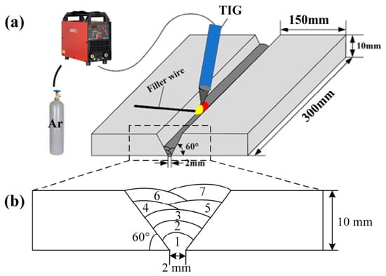
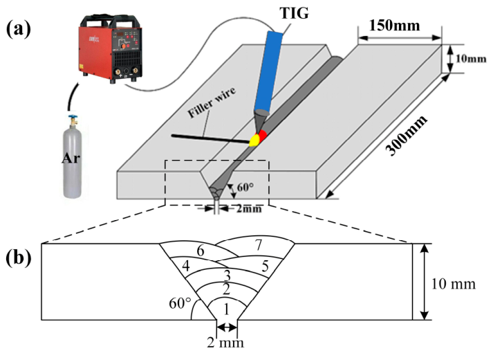
The welding process is schematically illustrated in Figure 1. The base metal was prepared with a 60° V-groove, and the root gap was 2 mm. Multilayer and multi-pass welded joints were fabricated by TIG. The Schematic of the groove and weld passes is shown in Figure 1b. 99% Ar is used as the shielding gas, with a flow rate of 12 L·min−1. The main welding parameters are listed in Table 2.
Figure 1.
Schematic of welding experiment: (a) welding experiment system; (b) groove and weld passes.
Table 2.
Welding parameters.
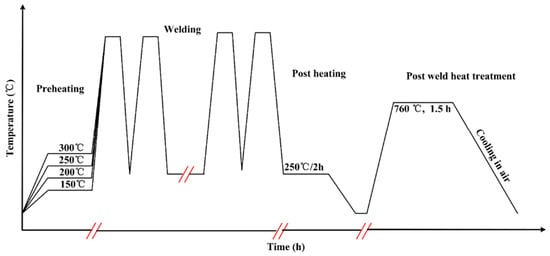
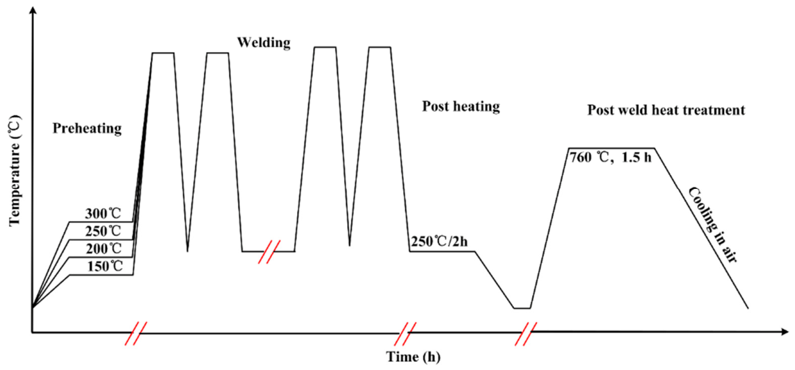
Before welding, the base metal was heated to different preheating temperatures, ranging from 150 °C to 300 °C. During the welding process, the preheating temperature and interlayer temperature need to be consistent in order to ensure that all weld passes have a consistent thermal cycle. Therefore, there are actually two experimental variables: preheating temperature and interlayer temperature. However, for ease of description, the experimental variable is still described as preheating temperature. During the welding process, the heat input for all specimens was fixed at 12 kJ/cm. The TM902C industrial thermometer (Shenzhen Anseny Electronic Technology Co., Ltd., Shenzhen, China) was used to measure the temperature of the test plate. After welding, the specimens were immediately subjected to post-weld heating at 250 °C to delay cooling. Subsequently, post-weld heat treatment (PWHT) was performed at 760 °C for 1.5 h. The schematic diagram of the welding and heat treatment process is shown in Figure 2.
Figure 2.
The schematic diagram of the welding and heat treatment process.
Following the completion of heat treatment, all welded joints underwent radiographic testing, and no defects were detected. This indicates that sound welded joints were successfully produced under the selected welding conditions. The macroscopic morphology of the welded joint is shown in Figure 3.
Figure 3.
Macroscopic morphology of the welded joint: (a) Macroscopic morphology; (b) Sectional morphology.
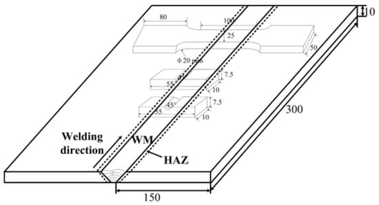
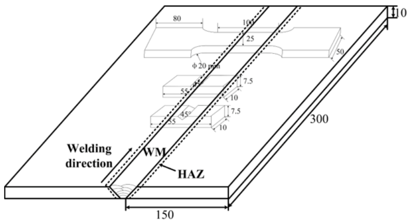
The specimens were cut from the new type of low-activity martensitic steel plate after welding using an electric discharge wire cutting machine. The schematic diagram of the test sample is shown in Figure 4.
Figure 4.
Schematic diagram of samples (Unit: mm).
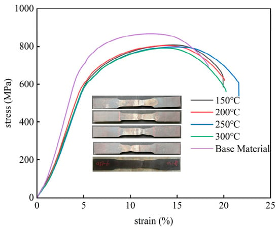
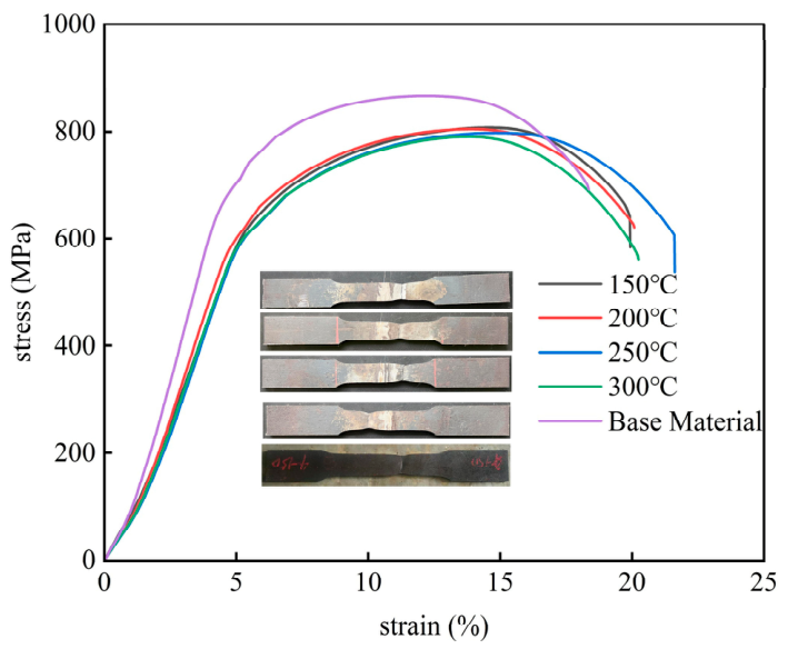
The tensile properties of the welded joints were tested using a universal testing machine (HUT605A, Shenzhen Wance Testing Equipment Co., Ltd., Shenzhen, China). The tensile tests were conducted in accordance with the GB/T 228.1-2021 standard [34]. The test results indicate that all welded joints fractured in the base metal. This suggests that preheating temperature has a limited influence on the tensile behavior of the welded joints within the investigated range. The tensile curves of welded joints at different preheating temperatures are shown in Figure 5. It is worth noting that, although all tensile specimens of the welded joints fractured in the base metal region far from the weld, their ultimate tensile strength was lower and their elongation was higher than those of the original base metal. This phenomenon may be attributed to the additional tempering of the base metal during post-weld heat treatment.
Figure 5.
Tensile curves of welded joints at different preheating temperatures.
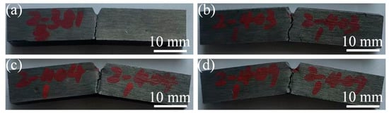
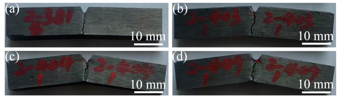
The impact toughness of the welded joints was tested using an impact testing machine (VU-1S, Jinan Hensgrand Instrument Co., Ltd., Jinan, China). The Charpy impact tests were performed following the GB/T 229-2020 standard [35]. Tests were carried out at room temperature. The impact test was conducted at room temperature. The notch of the impact specimen is V-shaped, with an angle of 45° and a depth of 2 mm. Three specimens were tested for each condition, separately for the WM and HAZ. The fracture surface morphology was observed using a field-emission scanning electron microscope (JSM-6700F, JEOL Ltd., Akishima (Tokyo), Japan). Macroscopic morphology of the impact testing sample is shown in Figure 6.
Figure 6.
Macroscopic morphology of the impact testing sample at different preheating temperatures: (a) 150 °C; (b) 200 °C; (c) 250 °C; (d) 300 °C.
A microhardness tester (HVT-1000, Guangdong Micro Accuracy Co., Ltd., Dongguan, China) was used to measure the microhardness of the welded joints, with an applied load of 1000 g and a dwell time of 15 s.
The metallographic specimens of the weld seam were ground, polished, and etched using a mixture solution (5 g FeCl3 + 50 mL HCl + 100 mL H2O) for 15 s. Following etching, the weld microstructure was examined via optical microscopy (OM, DSX500i, Olympus Corporation, Tokyo, Japan). The area fraction of δ-ferrite was statistically analyzed using Fiji software (ImageJ 2.16.0/1.54p/Java 21.0.7 (64-bit)). Transmission electron microscopy (TEM) (JEOL JEM-2100F, JEOL Ltd., Akishima (Tokyo), Japan) and energy-dispersive X-ray spectroscopy (EDS) (Oxford X-Maxn 80T, Oxford Instruments, Abingdon, UK)were performed on the weld metal of the specimen preheated at 250 °C to characterize its local microstructural features and elemental composition.
3. Results
3.1. The Effect of Preheating Temperature on the Microstructure of Welded Joints
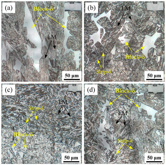
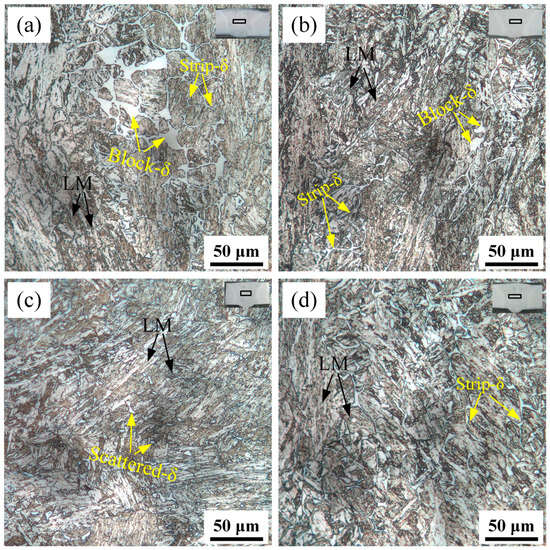
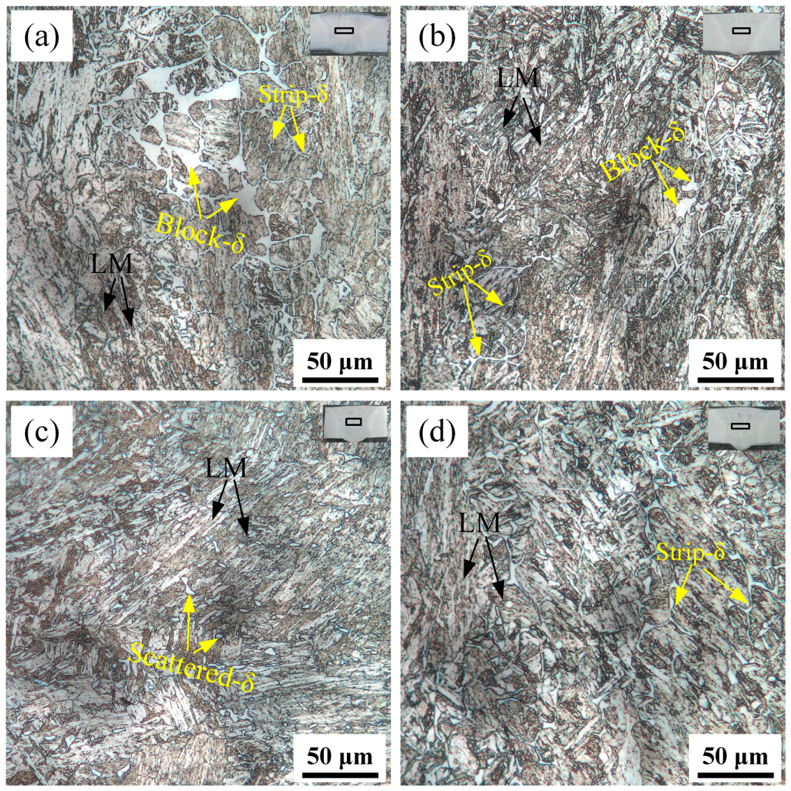
Figure 7 compares the microstructure of the upper part of the weld under different preheating temperatures. Overall, preheating temperature has a significant regulatory effect on the morphology and content of δ-ferrite. When the preheating temperature is 150 or 300 °C, the δ-ferrite is mainly blocky, but the size of the block is significantly different. When the preheating temperature is 150 °C, the size of the block is much larger than at 300 °C. When the preheating temperature is 200 and 250 °C, δ-ferrite exhibits a mixed form of blocky and strip coexistence. Its area ratio is significantly lower than that at the other two preheating temperatures. This shows that preheating temperature affects the nucleation and growth behavior of δ-ferrite by adjusting the cooling rate, and an appropriate cooling rate helps to suppress its precipitation.
Figure 7.
Microstructure of the upper part of the weld seam: (a) 150 °C; (b) 200 °C; (c) 250 °C; (d) 300 °C.
The middle and lower sections of the weld underwent the same welding thermal cycle, resulting in similar microstructures. The microstructure at the weld center under various preheating temperatures is shown in Figure 8. It is evident that the morphology and content of δ-ferrite exhibit differences with the increase in preheating temperature. At 150 °C, the δ-ferrite appears as small blocks and elongated strips (Figure 8a). When the preheating temperature rises to 200 and 250 °C, the δ-ferrite fraction decreases markedly, appearing only in scattered dots and short strips (Figure 8b,c). Further increasing the preheating temperature to 300 °C, the δ-ferrite fraction increases significantly, and it generally exhibits an elongated strip morphology (Figure 8d).
Figure 8.
Microstructure in the center of the weld seam: (a) 150 °C; (b) 200 °C; (c) 250 °C; (d) 300 °C.
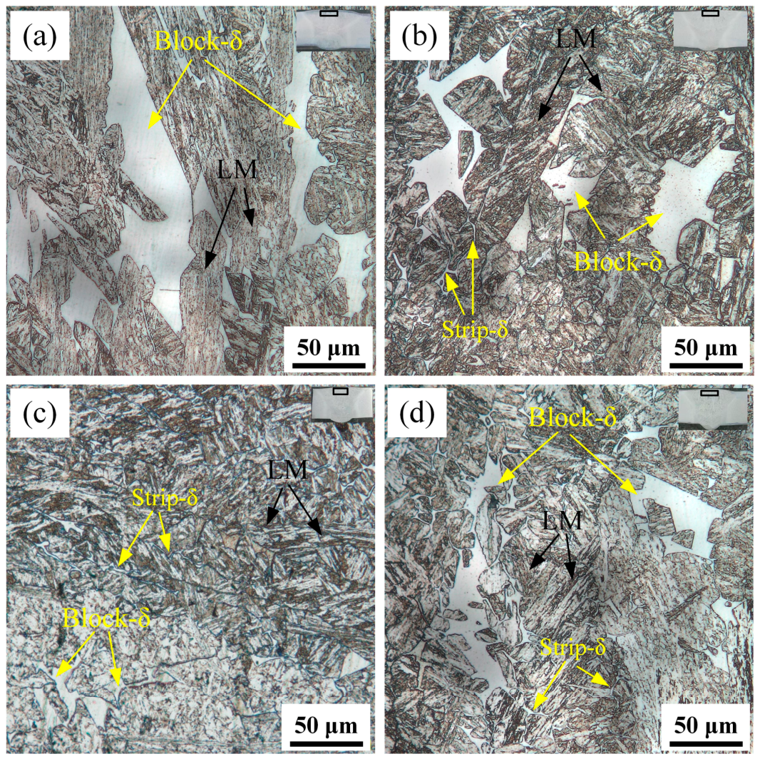
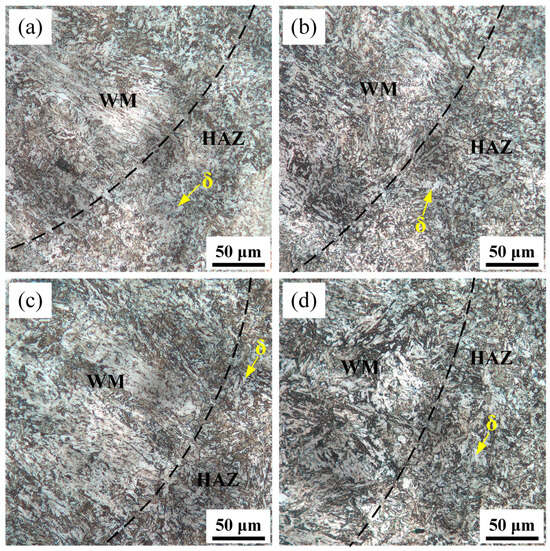
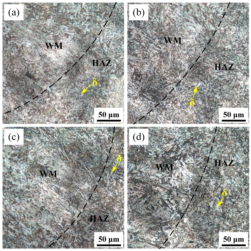
Figure 9 shows the microstructures of the HAZ under different preheating temperatures. Compared with the weld metal, the HAZ exhibited a lower δ-ferrite content. Overall, the HAZ microstructure predominantly consists of clumped δ-ferrite at all preheating temperatures, with no significant variation in its area fraction. This is mainly attributed to the fact that the HAZ undergoes only solid-state transformation without a liquid–solid transition, and the relatively rapid cooling rate restricts the full evolution of δ-ferrite. Unlike the solidified structure of the weld zone, significant changes in the morphology and content of δ-ferrite in the HAZ require prolonged high temperature. Therefore, within the preheating temperature range investigated in this study, the effect of preheating temperature on the HAZ microstructure is rather limited.
Figure 9.
Microstructure of the heat-affected zone: (a) 150 °C; (b) 200 °C; (c) 250 °C; (d) 300 °C.
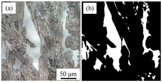
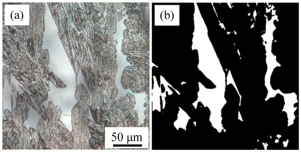
To quantify the δ-ferrite area fraction, the Advanced Weka Segmentation plugin in Fiji was used for initial image segmentation, followed by manual inspection and correction to eliminate misclassified regions. A representative optical micrograph and its corresponding segmentation result are shown in Figure 10a and Figure 10b, respectively. The δ-ferrite regions are clearly separated from the surrounding matrix in the segmented images. The δ-ferrite area fraction was calculated as the ratio of the total area occupied by δ-ferrite to the total area of the analyzed field of view.
Figure 10.
Representative optical micrograph and corresponding image segmentation for δ-ferrite area fraction measurement: (a) original optical micrograph; (b) segmented image.
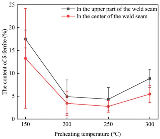
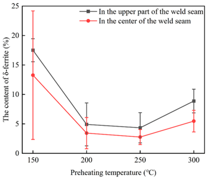
Based on the above method, the δ-ferrite area fractions in the upper and middle-lower regions of the weld under different preheating temperatures were quantitatively measured, as shown in Figure 11. For each region, five fields of view were analyzed, and each image was measured three times. The average of the three measurements was used as the δ-ferrite area fraction for each field of view. The results show that the δ-ferrite fraction exhibited a non-monotonic dependence on preheating temperature, reaching its minimum at 250 °C and maximum at 150 °C. This trend is consistent with the microstructural observations presented in Figure 7 and Figure 8. The error bars represent the standard deviation (SD) of the δ-ferrite area fractions measured across the five fields of view for each region.
Figure 11.
The δ-ferrite content of WM at different preheating temperatures.
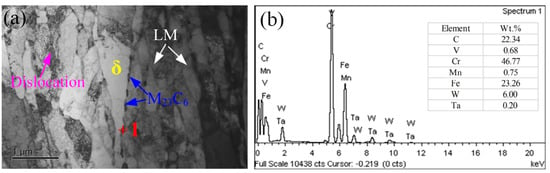
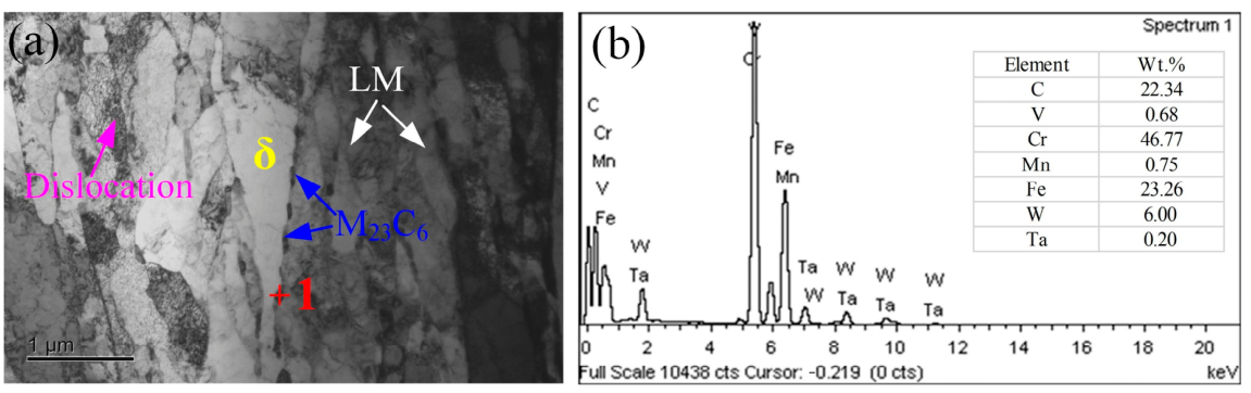
To further investigate the microstructural features, TEM observations and EDS analysis were performed on the weld metal of the specimen preheated at 250 °C, as shown in Figure 12. The microstructure consists primarily of lath martensite, δ-ferrite, and carbide precipitates. The lath martensite exhibits a relatively high dislocation density, whereas the δ-ferrite region contains comparatively fewer visible dislocations. In addition, continuous carbide precipitation is observed along the interfaces between δ-ferrite and lath martensite. Combined with the EDS results, these precipitates were identified as M23C6 carbides. Wang and Zhai [36,37] also reported similar carbide precipitation in the weld microstructures of CLAM and 9Cr2WVTa steels. The presence of δ-ferrite and interfacial M23C6 carbides may affect the impact toughness of the weld metal [38].
Figure 12.
TEM microstructure and EDS analysis of the weld metal preheated at 250 °C: (a) TEM image; (b) EDS spectrum of the carbide precipitates.
3.2. Mechanical Properties
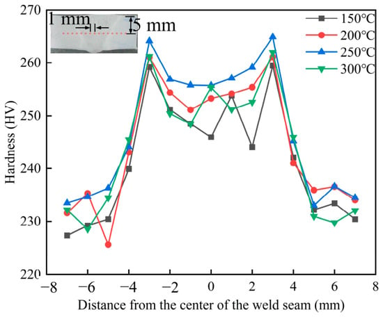
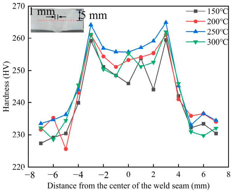
Figure 13 presents the microhardness distribution of the welded joints under different preheating temperatures. It can be observed that the hardness of the WM is higher than that of the BM and the HAZ. With increasing preheating temperature, the microhardness of the WM exhibits a non-monotonic trend of first increasing and then decreasing, reaching the maximum at 250 °C and the minimum at 150 °C. This trend is opposite to the variation in δ-ferrite content (Figure 10), which can be attributed to the fact that δ-ferrite has a lower hardness than lath martensite. Thus, an increase in δ-ferrite content leads to a reduction in the hardness of the weld.
Figure 13.
The influence of preheating temperature on the microhardness of welded joints.
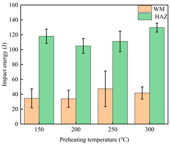
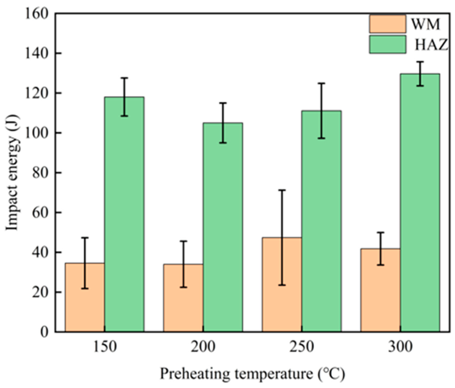
Figure 14 shows the variation in impact energy of the weld metal (WM) and heat-affected zone (HAZ) at different preheating temperatures. At preheating temperatures of 150 and 200 °C, the average impact energies of the WM were relatively low, at 34.57 and 34.00 J, respectively. As the preheating temperature increased to 250 °C, the impact energy increased markedly to 47.37 J, followed by a decrease to 41.80 J at 300 °C. This variation exhibits an inverse relationship with the evolution of the δ-ferrite content shown in Figure 10, suggesting that an increased δ-ferrite content is detrimental to the impact toughness of the WM. Among the investigated conditions, a preheating temperature of 250 °C tends to optimize impact energy and therefore appears to be the most favorable for improving the impact toughness of the WM.
Figure 14.
Impact energy of welded joints under different preheating temperatures.
In contrast, the impact energy of the HAZ remained above 100 J over the investigated preheating-temperature range, substantially higher than that of the WM, and exhibited relatively little variation with preheating temperature. This difference can be attributed to the distinct thermal histories and microstructural evolution of the two regions. The HAZ experiences solid-state phase transformations during the welding thermal cycle, whereas the WM undergoes melting and subsequent solidification. Consequently, the microstructural evolution of the WM, including the formation and variation in δ-ferrite, is more sensitive to changes in preheating temperature. The comparatively limited microstructural variation in the HAZ allows it to retain a relatively high level of impact toughness.
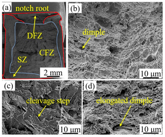
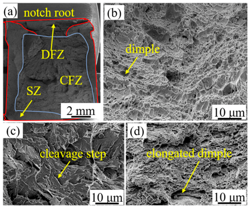
The impact fracture morphology is shown in Figure 15. As shown in Figure 15a, the fracture surface can be divided into three distinct regions: the dimple fracture zone (DFZ), shear zone (SZ), and cleavage fracture zone (CFZ). The microscopic fracture morphologies of these regions provide further insight into the variation in impact energy of the weld metal.
Figure 15.
Impact fracture morphology: (a) morphology of different impact energies; (b) DFZ; (c) CFZ; (d) SZ.
The DFZ and SZ exhibit typical ductile fracture characteristics, with numerous dimples distributed over the fracture surfaces (Figure 15b,d). Compared with those in the DFZ, some dimples in the SZ are noticeably elongated, which can be attributed to the pronounced shear deformation occurring during fracture. The presence of equiaxed and elongated dimples indicates substantial plastic deformation prior to fracture and, consequently, relatively high energy absorption.
In contrast, the CFZ exhibits a relatively smooth fracture surface characterized by distinct cleavage steps (Figure 15c), which are typical features of brittle cleavage fracture. Crack propagation in this region occurs rapidly with little plastic deformation, resulting in limited energy absorption. Therefore, the relative area fractions of the DFZ, SZ, and CFZ are closely associated with the macroscopic impact toughness. Larger fractions of the DFZ and SZ generally correspond to greater plastic deformation and higher impact energy, whereas an increased CFZ fraction indicates a stronger tendency toward brittle fracture and reduced impact toughness.
4. Discussion
4.1. The Effect of Preheating Temperature on the Phase Transformation of δ-Ferrite
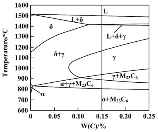
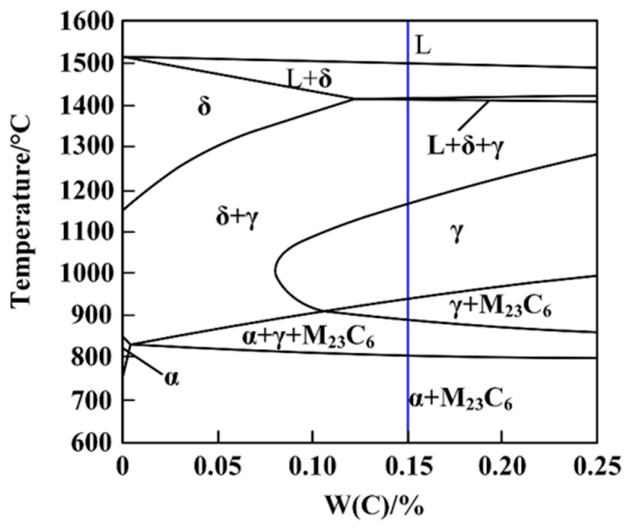
The formation of δ-ferrite is governed not only by the chemical composition of the welding wire but also by the thermal cycle during welding [16,39,40]. As illustrated in Figure 16, the equilibrium solidification path of the low-activation martensitic steel follows the sequence of L → L + δ → δ + γ → γ → γ + M23C6 → LM + γ + M23C6 → LM + M23C6 during cooling. Under equilibrium conditions, the primary δ-ferrite completely transforms into austenite before martensitic transformation, resulting in a fully martensitic microstructure after cooling. However, the actual solidification process during welding differs significantly from the equilibrium condition. The rapid cooling associated with welding suppresses the δ → γ transformation, leaving insufficient time for the primary δ-ferrite to transform completely. Consequently, some δ-ferrite is retained after martensitic transformation, resulting in a final microstructure consisting of LM + δ + M23C6 at room temperature.
Figure 16.
Equilibrium phase diagram.
During the welding process, the cooling rate of the weld seam can be calculated using the following formula [41]:
where λ is the thermal conductivity of the metal, Cp is the specific heat capacity, Tc is the actual temperature of the weld seam during the welding process, T0 is the preheating temperature or the interpass temperature, t is the thickness of the plate, Hnet is the heat input used during welding, and R is the cooling rate at a point on the weld centerline at just that moment when the point is cooling past Tc. From this formula, it can be seen that when all other conditions are the same, the larger T0, the slower the cooling rate R.
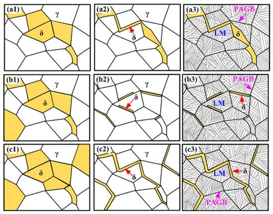
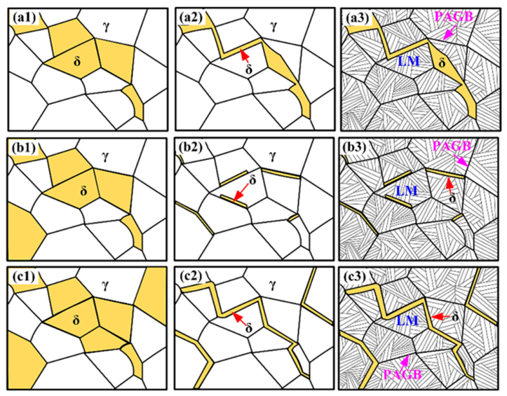
At a low preheating temperature of 150 °C, the molten pool has a relatively high cooling rate, thereby reducing the residence time of the weld metal within the δ-ferrite phase field. This shortened dwell time constrains both nucleation and growth of δ-ferrite, limiting its total amount formed. Concurrently, rapid cooling hinders atomic diffusion, kinetically suppressing the δ → γ solid-state phase transformation and thereby preventing the pre-existing δ-ferrite from fully transforming into austenite. As a result, a portion of the δ-ferrite persists at room temperature. Collectively, the restricted formation of δ-ferrite and its inhibited transformation stemming from the low preheating temperature lead to an elevated volume fraction of retained δ-ferrite in the final microstructure (Figure 17(a1–a3)).
Figure 17.
The effect of preheating temperature on ferrite transformation. (a1–a3) 150 °C; (b1–b3) 200 °C and 250 °C; (c1–c3) 300 °C.
When the preheating temperature is maintained at a moderate level of 200~250 °C, the resulting cooling rate is correspondingly moderate. This thermal condition facilitates complete precipitation of δ-ferrite within the high-temperature phase field and affords sufficient time for atomic diffusion to enable the majority of δ-ferrite to undergo the δ → γ solid-state transformation during cooling. Consequently, the volume fraction of residual δ-ferrite in the room-temperature microstructure is minimized (Figure 17(b1–b3)).
However, as the preheating temperature further increases to 300 °C, the cooling rate markedly decreases, thereby extending the residence time of the molten pool within the δ-ferrite region. Under these conditions, δ-ferrite undergoes both complete precipitation and significant coarsening. Although slower cooling affords greater time for the δ → γ solid-state transformation, the concurrent increase in δ-ferrite volume fraction and grain size substantially lengthens the atomic diffusion distance required for its full conversion to austenite, leading to the retention of coarse, untransformed δ-ferrite in the structure. At this point, the combined effect of the large amount of formation and insufficient transformation causes the content of δ-ferrite in the room-temperature structure to increase again (Figure 17(c1–c3)).
4.2. The Relationship Between the Content of δ Ferrite in Welds and Their Mechanical Properties
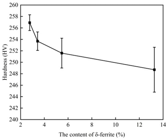
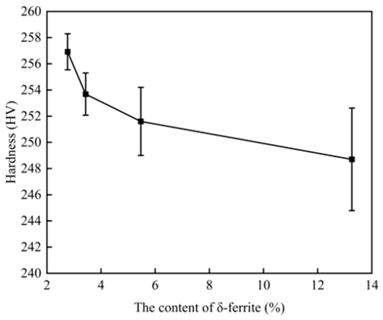
The variation in hardness with δ-ferrite content is shown in Figure 18. As the δ-ferrite content in the weld increases, the average microhardness of the weld decreases. The solid solution strengthening effect of elements in δ-ferrite is weak, and its dislocation density is significantly lower than that of martensite, resulting in lower hardness of δ-ferrite. Additionally, the grain boundary or lath interface strengthening in martensite also contributes to the higher hardness of martensite compared to δ-ferrite.
Figure 18.
The variation in hardness with δ-ferrite content.
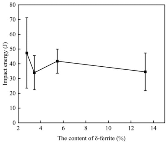
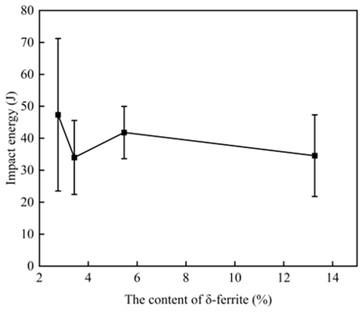
The variation in impact energy with δ-ferrite content is shown in Figure 19. Although there are slight fluctuations in the data, overall the impact toughness decreases with the increase in δ-ferrite content in the weld seam. During impact deformation, the lower-strength δ-ferrite deforms plastically first. In addition, a large gradient of stress and strain concentration occurs at the interface between delta ferrite and martensite, which becomes the nucleation point of cracks.
Figure 19.
The variation in impact energy with δ-ferrite content.
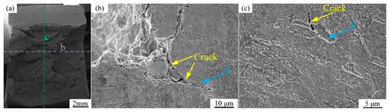
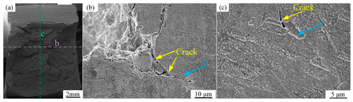
The non-monotonic variation in the impact toughness of 9Cr steels has been widely associated with the presence of δ-ferrite. To clarify the micromechanisms underlying the anomalous evolution of impact toughness in the SIMP steel welded joints, the cross-sectional morphologies of the fractured impact specimens were examined along different orientations, as shown in Figure 20. After impact testing, the fractured specimen was sectioned along the two lines indicated in Figure 20a, whose intersection was located near the crack initiation site.
Figure 20.
The cross-sectional morphologies of impact fracture surfaces with different orientations: (a) Sample cutting position; (b) The crack initiation area near the surface of the specimen; (c) The crack propagation area inside the sample.
The corresponding cross-sectional morphologies are shown in Figure 20b,c. As shown in Figure 20b, cracks in the initiation region preferentially nucleated and propagated along the δ-ferrite/martensite interfaces under impact loading. The weld metal consists primarily of high-strength tempered martensite and comparatively soft, ductile δ-ferrite, resulting in a pronounced mechanical mismatch between the two phases. Under impact loading, this mismatch hinders strain compatibility across the phase boundaries and promotes local stress concentration at the δ-ferrite/martensite interfaces. Once the local stress exceeds the interfacial resistance to fracture, microcracks can preferentially nucleate at these sites. Consequently, compared with a more homogeneous martensitic microstructure, the introduction of δ-ferrite/martensite interfaces provides preferential sites for crack initiation and reduces the resistance to fracture initiation.
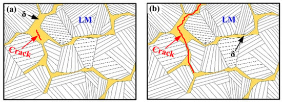
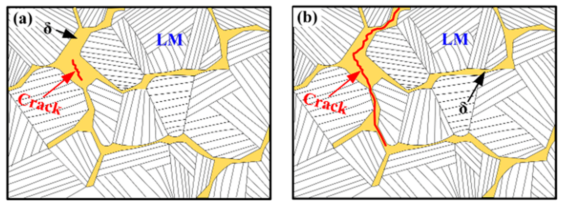
Further observations along the cleavage-propagation direction (Figure 20c) revealed that cracks tended to propagate along the δ-ferrite/martensite interfaces and, in some regions, through the interiors of δ-ferrite grains. TEM observations in Figure 11 revealed continuous carbide precipitation along the δ-ferrite/martensite interfaces. These interfacial M23C6 carbides, together with the microstructural differences between δ-ferrite and martensite, may contribute to local deformation heterogeneity and influence crack propagation under impact loading. The interfaces and δ-ferrite regions may provide relatively low-resistance paths for crack propagation compared with the surrounding martensitic matrix. As a result, the presence of δ-ferrite may facilitate crack extension and reduce the energy required for fracture propagation. Furthermore, as the δ-ferrite fraction increases, the δ-ferrite regions may become increasingly interconnected, forming a network-like distribution that may further facilitate crack propagation by providing more continuous paths. These observations suggest that δ-ferrite plays an important role in both crack initiation and propagation and may contribute to the deterioration of impact toughness in the welded joints. A schematic illustration of the proposed crack-propagation mechanism during impact fracture is presented in Figure 21.
Figure 21.
The schematic diagram of crack propagation: (a) Crack initiation; (b) Crack propagation.
5. Conclusions
This study systematically investigated the effect of preheating temperature on the microstructure and mechanical properties of the new type of low-activity martensitic steel welded joints. The evolution of the weld microstructure was clarified, and the role of δ-ferrite in governing the impact toughness of the weld metal was elucidated. The main conclusions are summarized as follows:
- (1)
- The preheating temperature significantly influences the δ-ferrite content in the weld metal. Both relatively low and high preheating temperatures promote the formation of δ-ferrite, whereas a preheating temperature of 250 °C results in the lowest δ-ferrite content. Under this condition, the weld metal exhibits the most favorable impact toughness among the investigated conditions.
- (2)
- An increased δ-ferrite content has a detrimental effect on the mechanical properties of the weld metal. With increasing δ-ferrite content, both the hardness and impact toughness of the weld metal decrease, indicating that suppression of δ-ferrite formation is beneficial for improving weld performance.
- (3)
- Under impact loading, cracks preferentially initiate and propagate along δ-ferrite regions and δ-ferrite/martensite interfaces. These regions therefore act as preferential fracture paths and represent microstructural weak points that reduce the impact toughness of the welded joint.
- (4)
- Although the present findings provide guidance for optimizing the welding procedure of SIMP steel, further development of compositionally optimized matching filler wires may be necessary to further suppress δ-ferrite formation and improve the impact toughness of welded joints.
Author Contributions
Conceptualization, Y.Z. and S.Y.; methodology, Y.Z., S.Y. and H.Z.; software, Y.Z. and C.D.; validation, Y.Z., S.Y., H.Z., X.Y. and C.D.; formal analysis, Y.Z., S.Y., H.Z., X.Y., C.D., C.Y. and J.H.; investigation, Y.Z., S.Y., H.Z., X.Y. and C.D.; resources, C.Y. and J.H.; data curation, Y.Z., S.Y., H.Z. and C.D.; writing—original draft preparation, Y.Z. and S.Y.; writing—review and editing, H.Z., X.Y., C.D., C.Y. and J.H.; visualization, Y.Z., S.Y., H.Z., X.Y. and C.D.; supervision, C.Y. and J.H.; project administration, C.Y. and J.H.; funding acquisition, C.Y. and J.H. All authors have read and agreed to the published version of the manuscript.
Funding
The present work was financially funded by the National Natural Science Foundation of China (U25B20115, U2032142, 52575392). The financial support is gratefully acknowledged.
Data Availability Statement
The original contributions presented in this study are included in the article. Further inquiries can be directed to the corresponding authors.
Conflicts of Interest
Author Xiaoquan Yu was employed by the company Zhejiang Provincial Innovation Center of Laser Intelligent Equipment Technology. The remaining authors declare that the research was conducted in the absence of any commercial or financial relationships that could be construed as a potential conflict of interest.
Abbreviations
The following abbreviations are used in this manuscript:
| GTAW | Gas Tungsten Arc Welding |
| TIG | Tungsten Inert Gas |
| HAZ | Heat-affected zone |
| WM | Weld metal |
| BM | Base material |
| DFZ | Dimple fracture zone |
| CFZ | cleavage fracture zone |
| SZ | shear zone |
References
- Alemberti, A.; Valery, S.; Craig, F.; Minoru, T. Overview of lead-cooled fast reactor activities. Prog. Nucl. Energy 2014, 77, 300–307. [Google Scholar] [CrossRef] [Scilit]
- Smith, C.; Cinotti, L. Lead-Cooled Fast Reactor. In Handbook of Generation IV Nuclear Reactors; Woodhead Publishing: Cambridge, UK, 2016; pp. 119–155. [Google Scholar] [CrossRef] [Scilit]
- Cinotti, L.; Smith, C.; Sekimoto, H. Lead-Cooled Fast Reactor (LFR) Overview and Perspectives; Lawrence Livermore National Laboratory (LLNL): Livermore, CA, USA, 2009.
- Yang, K.; Yan, W.; Wang, Z.; Shan, Y.; Shi, Q.; Shi, X.; Wang, W. Development of a novel structural material (SIMP steel) for nuclear equipment with balanced resistances to high temperature, radiation and liquid metal corrosion. Acta Metall. Sin. 2016, 52, 1207–1221. [Google Scholar] [CrossRef]
- Liu, C.; Zhao, M.; Unenbayar, T.; Zhao, Y.; Xie, B.; Tian, Y. Hot Deformation Behavior of a New Nuclear Use Reduced Activation Ferritic/Martensitic Steel: C. Acta Metall. Sin. (Engl. Lett.) 2019, 32, 825–834. [Google Scholar] [CrossRef] [Scilit]
- Duan, Z.; Xiang, H.; Qiao, P.; Wen, Q.; Ouyang, H. Progress in understanding the formation and deposition behaviors of corrosion and oxidation products in lead-cooled fast reactors. Prog. Nucl. Energy 2025, 184, 105742. [Google Scholar] [CrossRef] [Scilit]
- Chen, Y.; Zhang, W.; Lyu, S.; Dai, J. Effect of Manual Tungsten Inert Gas Welding on the Microstructure and Mechanical Properties of Welded Joints in Thick SIMP Steel Plates. Materials 2026, 19, 2944. [Google Scholar] [CrossRef] [Scilit] [PubMed]
- Liu, T.; Yang, C.; Fan, X.; Yun, D.; Liu, W.; Popovic, M.; Zhao, B.; Xia, H.; Liu, Z.; Qiu, J. Degradation mechanism of oxide film on SIMP steel in LBE at temperatures above 550 °C. Nucl. Eng. Technol. 2026, 58, 104131. [Google Scholar] [CrossRef] [Scilit]
- Ma, Z.; Zhou, T.; Jin, P.; Gao, X.; Liu, C.; Chang, H.; Pan, L.; Shen, T.; Wang, Z. Influence of temperature on the microstructural evolution of SIMP and T91 steels in liquid lead-bismuth eutectic: Experiments and molecular dynamics simulations. Corros. Sci. 2023, 222, 111411. [Google Scholar] [CrossRef] [Scilit]
- Lan, Y.; Cui, M.; Jin, P.; Li, J.; Yang, Y.; Chen, Z.; Li, D.; Cao, Y.; Shen, T.; Wang, Z. In situ TEM evidence for the role of large helium bubbles in the irradiation hardening and embrittlement of SIMP Steel. J. Mater. Sci. Technol. 2027, 287, 72–81. [Google Scholar] [CrossRef] [Scilit]
- Liao, Q.; Li, B.; Ge, F.; Wang, R.; Zhang, H.; Krsjak, V.; Shen, Y. Investigation into creep-to-rupture of SIMP steel in stagnant LBE at 300–450 °C. Mater. Corros. 2022, 73, 784–797. [Google Scholar] [CrossRef] [Scilit]
- Ma, Z.; Shen, T.; Zhu, J.; Jin, P.; Gao, X.; Wang, Z. Microstructural evolution of SIMP steel under stress/lead–bismuth corrosion synergy. Mater. Des. 2025, 259, 114942. [Google Scholar] [CrossRef] [Scilit]
- Li, B.; Wang, Z.; Wei, K.; Shen, B.; Yao, C.; Zhang, H.; Shen, Y.; Lu, X.; Xiong, A.; Han, W. Evaluation of helium effect on irradiation hardening in F82H, ODS, SIMP and T91 steels by nano-indentation method. Fusion Eng. Des. 2019, 142, 6–12. [Google Scholar] [CrossRef] [Scilit]
- Yang, Z.; Yang, J.; Liao, Q.; Xu, S.; Li, B. Effect of helium concentration on irradiation damage of Fe-ion irradiated SIMP steel at 300 °C and 450 °C. Chin. Phys. B 2021, 30, 056107. [Google Scholar] [CrossRef] [Scilit]
- Ma, G.; Tang, Z.; Bao, H.; He, X. Research Progress on Liquid Metal Embrittlement Behavior of Candidate Structural Materials for Lead-Bismuth Reactors. Spec. Steel 2025, 46, 24–34. [Google Scholar] [CrossRef]
- Mayr, P.; Schlacher, C.; Siefert, J. Microstructural features, mechanical properties and high temperature failures of ferritic to ferritic dissimilar welds. Int. Mater. Rev. 2019, 64, 1–26. [Google Scholar] [CrossRef] [Scilit]
- Wang, J.; Zhu, K.; Zhou, J.; Lu, X. Effects of peak temperatures and cooling rates on delta ferrite formation and mechanical properties for heat affected zones in 9Cr-RAFM steel. Int. J. Press. Vessel. Pip. 2021, 192, 104399. [Google Scholar] [CrossRef] [Scilit]
- Anderko, K.; Schafer, L.; Maternamorris, E. Effect of the δ-ferrite phase on the impact properties of martensitic chromium steels. J. Nucl. Mater. 1991, 179, 492–495. [Google Scholar] [CrossRef] [Scilit]
- Wang, J.; Lu, S.; Dong, W.; Li, D.; Rong, L. Microstructural evolution and mechanical properties of heat affected zones for 9Cr2WVTa steels with different carbon contents. Mater. Des. 2014, 64, 423–431. [Google Scholar] [CrossRef] [Scilit]
- Ahn, S.; Kang, N. The Effects of δ-ferrite on Weldment of 9–12% Cr Steels. J. Weld. Join. 2013, 31, 8–16. [Google Scholar] [CrossRef] [Scilit]
- Sam, S.; Das, C.; Ramasubbu, V.; Albert, S.; Bhaduri, A.; Jayakumar, T.; Rajendra, E. Delta ferrite in the weld metal of reduced activation ferritic martensitic steel. J. Nucl. Mater. 2014, 455, 343–348. [Google Scholar] [CrossRef] [Scilit]
- Wu, S.; Shi, Y.; Zhang, G.; Zhang, S.; Liao, H.; Wang, X.; Qin, Z. Improving impact toughness of heavy section reduced activation ferritic martensitic CLF-1 steel joints with electron beam welding. J. Nucl. Mater. 2020, 531, 152031. [Google Scholar] [CrossRef] [Scilit]
- Wu, D.; Tian, W.; Zhang, K.; Lu, S. Formation of delta-ferrite and its effect on impact toughness of GTAW weld metals in a 12 wt-% Cr steel. Sci. Technol. Weld. Join. 2023, 28, 242–248. [Google Scholar] [CrossRef] [Scilit]
- Liu, Z.; Cao, R. Research progress on toughness control of low carbon martensitic stainless steel weld metal. J. Mech. Eng. 2025, 61, 48–62. [Google Scholar] [CrossRef] [Scilit]
- Sonar, T.; Ivanov, M.; Trofimov, E.; Liu, K.; Shcherbakov, I.; Shaburova, N.; Samoilovskikh, P. A critical review on dissimilar welding of ferritic-martensitic steel and austenitic stainless steel using gas tungsten arc welding process: Weldability issues, processing, and performance characteristics of joints. J. Manuf. Process. 2025, 133, 811–864. [Google Scholar] [CrossRef] [Scilit]
- Sajunath, K.; Das, C.; Albert, S.; Raju, S.; Bhaduri, A.K. Formation of Delta-Ferrite in the Weld Metal of 9-12Cr Steels. Indian Weld. J. 2013, 46, 41. [Google Scholar] [CrossRef] [Scilit]
- Lyu, Z.; Long, B.; Lienert, L.; Li, L. Effects of Preheating on the Microstructure of Laser-DED AISI 420. Weld. J. 2024, 12, 103. [Google Scholar] [CrossRef] [Scilit]
- Mayr, P.; Palmer, T.; Elmer, J.; Specht, E.; Allen, S. Formation of Delta Ferrite in 9 Wt Pct Cr Steel Investigated by In-Situ X-Ray Diffraction Using Synchrotron Radiation. Metall. Mater. Trans. A 2010, 41, 2462–2465. [Google Scholar] [CrossRef] [Scilit]
- Lyu, Z.; Hoffmann, W.; Khan, W.; Lienert, T.; Li, L. A mechanistic study of retained δ-ferrite in additively-manufactured Grade 91 steel. J. Mater. Res. Technol. 2025, 36, 5128–5143. [Google Scholar] [CrossRef] [Scilit]
- Mahlalela, S.; Pistorius, P. Delta ferrite in modified 9Cr–1Mo steel weld metal. Weld. World 2025, 69, 3613–3624. [Google Scholar] [CrossRef] [Scilit]
- Mahlalela, S.; Pistorius, P. Influence of alloying elements and cooling rate on the presence of delta ferrite in modified 9Cr–1Mo as-welded microstructure produced by gas–metal arc welding. Weld. World 2023, 67, 1169–1180. [Google Scholar] [CrossRef] [Scilit]
- Saini, N.; Mulik, R.; Mahapatra, M.; Li, L. Effect of preheating temperature on retention of δ-ferrite in ASTM A355 grade P92. Metall. Mater. Trans. B 2023, 54, 315–330. [Google Scholar] [CrossRef] [Scilit]
- Rajani, H.; Torkamani, H.; Sharbati, M.; Raygan, S. Corrosion resistance improvement in Gas Tungsten Arc Welded 316L stainless steel joints through controlled preheat treatment. Mater. Des. 2012, 34, 51–57. [Google Scholar] [CrossRef] [Scilit]
- GB/T 228.1-2021; Metallic Materials—Tensile Testing—Part 1: Method of Test at Room Temperature. Standards Press of China: Beijing, China, 2021.
- GB/T 229-2020; Metallic Materials—Charpy Pendulum Impact Test Method. Standards Press of China: Beijing, China, 2020.
- Jian, W.; Shanping, L.; Rong, L.; Dianzhong, L. Effect of silicon contents on the microstructures and mechanical properties of heat affected zones for 9Cr2WVTa steels. J. Nucl. Mater. 2016, 470, 1–12. [Google Scholar] [CrossRef] [Scilit]
- Zhai, Y.; Huang, B.; Zhang, J.; Zhang, B.; Liu, S.; Huang, Q. Effect of weld spacing on microstructure and mechanical properties of CLAM electron beam welding joints. Fusion Eng. Des. 2016, 112, 440–449. [Google Scholar] [CrossRef] [Scilit]
- Sun, Q.; Wei, S.; Lu, S. Coupling Effect Mechanism of the δ-Ferrite and M23C6 on the Mechanical Properties of 9Cr-Steel Deposited Metals. Acta Metall. Sin. (Engl. Lett.) 2025, 38, 121–138. [Google Scholar] [CrossRef] [Scilit]
- David, S.; Vitek, J. Correlation between solidification parameters and weld microstructures. Int. Mater. Rev. 1989, 34, 213–245. [Google Scholar] [CrossRef] [Scilit]
- Chen, X.; Huang, Y.; Shen, Z.; Chen, J.; Lei, Y.; Zhou, J. Effect of thermal cycle on microstructure and mechanical properties of CLAM steel weld CGHAZ. Sci. Technol. Weld. Join. 2013, 18, 302–308. [Google Scholar] [CrossRef] [Scilit]
- Arivazhagan, B.; Srinivasan, G.; Albert, S.; Bhaduri, A. A study on influence of heat input variation on microstructure of reduced activation ferritic martensitic steel weld metal produced by GTAW process. Fusion Eng. Des. 2011, 86, 192–197. [Google Scholar] [CrossRef] [Scilit]



Disclaimer/Publisher’s Note: The statements, opinions and data contained in all publications are solely those of the individual author(s) and contributor(s) and not of MDPI and/or the editor(s). MDPI and/or the editor(s) disclaim responsibility for any injury to people or property resulting from any ideas, methods, instructions or products referred to in the content. |
© 2026 by the authors. Licensee MDPI, Basel, Switzerland. This article is an open access article distributed under the terms and conditions of the Creative Commons Attribution (CC BY) license.