


Abstract
A custom low-chromium MoNiCr alloy produced by wire-fed laser directed energy deposition (W-DED) was exposed to eutectic LiF–BeF2 (FLiBe) at 750 °C for 1000 h to assess corrosion of the retained deposition surface. A nominally 100 × 100 × 100 mm cube was divided into as-built (AB) and hot-isostatically pressed (HIP) portions. Two coupons were extracted from each of the X–Y, Z–X, and Z–Y surface layers of each portion, giving 12 coupons. Each coupon was fully immersed in a separate nominally equal salt charge within a graphite crucible enclosed in an individually sealed AISI 304 capsule. Characterization focused on the original W-DED face. Optical profilometry compared exposed coupons with adjacent unexposed reference regions. Cross-sectional scanning electron microscopy and energy-dispersive X-ray spectroscopy assessed microstructure and near-surface chemistry. The topography measurements showed substantial spatial variability and did not establish a consistent dependence on orientation or material condition. Backscattered-electron images and semiquantitative elemental profiles indicated a shallow near-surface region associated with Cr depletion, without establishing a quantitative penetration depth or corrosion rate. The results provide descriptive screening observations for retained W-DED surfaces under the specific static exposure conditions. Unmeasured salt redox potential and impurity concentrations, together with the limited replication, constrain their use in material qualification.
1. Introduction
Molten-salt reactors (MSRs) require structural materials that maintain mechanical integrity in contact with chemically aggressive fluoride salts at elevated temperatures. Nickel–molybdenum–chromium alloys are important candidates: nickel provides a comparatively stable matrix, molybdenum contributes to high-temperature strength, and chromium improves resistance to oxidation in air but is susceptible to dissolution in fluoride salts [1,2]. Conventional Hastelloy N-type alloys typically contain approximately 6–8 wt.% Cr. The feedstock used here contains 5.80 wt.% Cr and is described as a custom MoNiCr alloy based on the same general alloy concept. Compositional or qualification equivalence to commercial Hastelloy N is not assumed.
Additive manufacturing can shorten development cycles and produce near-net-shape components with channels and other geometries that are difficult to manufacture conventionally. Wire-fed directed energy deposition is particularly relevant to large components because it is not constrained by a powder-bed build envelope and uses feedstock that can be easier to procure, handle, and qualify than metal powder [3,4]. The process also produces orientation-dependent ridges, waviness, melt-pool traces, partially fused features, and microsegregation. Surface geometry affects the actual area in contact with salt, while local compositional heterogeneity may influence dissolution and mass transport [5,6,7].
This study focuses on the retained deposition surface. Large W-DED components may contain internal channels, enclosed cavities, or locally inaccessible surfaces that cannot readily be ground, machined, or polished. Removing the original surface from corrosion coupons can eliminate the combined effects of deposition topography, near-surface segregation, and local salt access that may occur in service. The nominally 100 mm cube used here allowed surface layers to be extracted directly from a large-format W-DED build.
Previous Ni–Mo–Cr studies demonstrate the importance of salt condition, containment, and microstructure. Muránsky et al. compared Hastelloy N, GH3535, and MONICR in static FLiNaK at 650 °C for 200, 500, and 750 h. MONICR was the least affected, with differences attributed to grain-boundary density and carbide populations [8]. Danon et al. tested GH3535 parent metal and matching weld metal in FLiNaK at 750 °C for 500 h. The somewhat higher resistance of the weld metal was associated with its lower density of high-angle grain boundaries and the presence of M6C carbides in the parent material [9]. In purified LiF–BeF2 (66:34 mol.%) at 700 °C for 1000 h, Zheng et al. reported a Cr-depleted region approximately 3.5 µm deep in a pure-Ni capsule, whereas graphite containment produced a carbide-containing subsurface region extending to approximately 7 µm [10]. These results illustrate sensitivity to microstructure and containment chemistry; the different test conditions prevent direct kinetic comparison with the present exposure.
Evidence on retained additive-manufacturing surfaces exposed to molten salts remains limited. An Idaho National Laboratory study retained the printed surface layers of laser powder bed fused (L-PBF) 316H specimens and reported spatially heterogeneous depletion after exposure to NaCl–MgCl2. Studies of polished or electropolished specimens primarily address microstructure-dependent attack after removal of the original deposition surface [11,12,13,14,15,16,17]. Jokisaari et al. identified gravimetry, salt characterization, and replication as essential elements of rigorous corrosion testing of additively manufactured materials [18]. The present study examines retained W-DED surfaces under static FLiBe exposure in individual capsules. Its interpretation is restricted by the experimental controls and measurements available.
Hot isostatic pressing (HIP) can close internal defects and modify the solidification microstructure while leaving the external deposition relief largely intact. This study examines surface topography, cross-sectional morphology, and near-surface elemental redistribution in AB and HIP material from three build orientations after 1000 h in FLiBe at 750 °C. With two coupons per orientation and material condition, the results are interpreted as descriptive screening observations. Detailed characterization of bulk AB/HIP microstructure and mechanical properties is the subject of a separate contribution.
2. Materials and Methods
2.1. Alloy and W-DED Processing
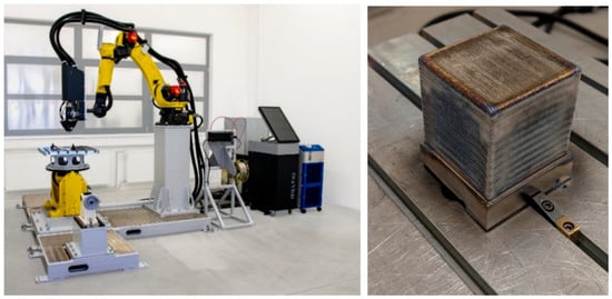
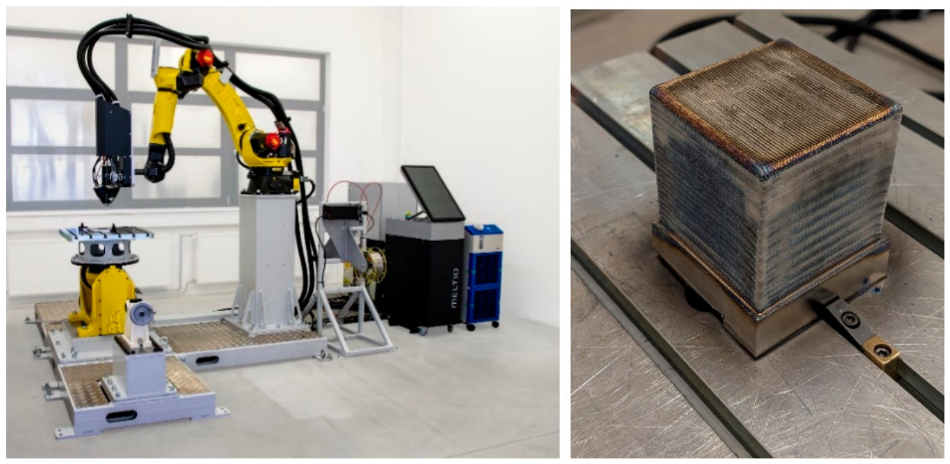
The custom low-chromium MoNiCr alloy and 1.05 mm diameter wire feedstock were developed and manufactured by COMTES FHT a.s. (Dobřany, Czech Republic). The company also manufactured the nominally 100 mm W-DED cube under a paid subcontract to Research Centre Řež (CVŘ) within the institutional support program. Deposition was performed under argon using a Meltio wire-laser deposition head (Meltio, Linares, Spain) mounted on a FANUC robotic system (FANUC Corporation, Oshino-mura, Japan) (Figure 1). The deposition speed was 8 mm s−1, the layer height was 1.1 mm, and the track spacing was 1.0 mm. The laser power was 1000 W. A zig-zag deposition strategy with a 45° rotation between successive layers was used.
Figure 1.
W-DED fabrication of the MoNiCr cube by COMTES FHT a.s.: Meltio wire-laser deposition system mounted on a FANUC robotic platform (left) and the as-built, nominally 100 mm MoNiCr cube (right).
Table 1 gives the nominal alloy composition.
Table 1.
Nominal composition of the MoNiCr wire feedstock (wt.%).
Before extraction of the surface layers, the nominally 100 × 100 × 100 mm deposited cube was divided into two halves at Research Centre Řež. One half remained in the as-built (AB) condition; the other underwent HIP at 1200 °C and 150 MPa with a 2 h dwell. One approximately 6 mm thick surface layer was extracted from each of the X–Y, Z–X, and Z–Y planes of each half. The bottom face in contact with the build platform was excluded. Two approximately 60 × 18 × 6 mm coupons were cut from each surface layer, yielding six AB and six HIP coupons, with two coupons per orientation and material condition. Each coupon retained one original W-DED face. The remaining faces were produced by wire electrical discharge machining (wire-EDM) during extraction and were excluded from surface characterization. Corrosion assessment focused on the retained deposition face; bulk mechanical testing was outside the scope of this campaign.
2.2. FLiBe Preparation and Static Exposure
The exposure medium was eutectic LiF–BeF2 (66:34 mol.%), prepared from analytical-reagent-grade (p.a.) constituents supplied by Shanghai Muhong Industrial Co., Ltd. (Shanghai, China). The salts were weighed to the target composition and handled in a nitrogen glovebox supplied from a cryogenic storage vessel. The mixture was melted in a glassy-carbon crucible and held at 800 °C for 2 h before loading. No further chemical purification or analytical characterization was performed. Residual H2O, O2, HF, and metallic impurity concentrations and the redox potential of the prepared salt were not measured. The exposed salt therefore cannot be described as analytically verified or redox-controlled.
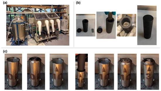
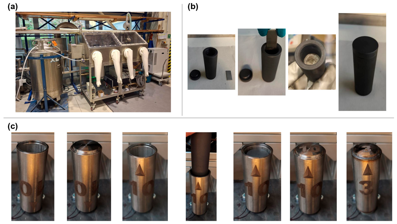
Inside the glovebox, each coupon was placed in a separate graphite crucible and fully immersed in a nominally equal salt charge. The crucible had an internal diameter of 20 mm. The approximately 60 × 18 × 6 mm coupon was immersed along its 60 mm length, with a nominal salt level 10 mm above its upper end. Subtracting the coupon volume from the filled crucible volume gives a nominal salt volume of 15.51 cm3. The total wetted geometric area of the coupon was 30.96 cm2, corresponding to V/A ≈ 0.50 mL cm−2 (A/V ≈ 2.00 cm−1). Using the FLiBe density correlation ρ = 2.41 − 4.88 × 10⁻⁴ T, where ρ is in g cm−3 and T is in K [19], the estimated density at 750 °C is 1.911 g cm−3, and the corresponding salt mass is 29.6 g. These are estimates based on nominal geometry and the published density correlation; individual salt charges were not directly weighed. After the FLiBe solidified, each crucible was closed with a threaded graphite lid and placed inside a cylindrical AISI 304 enclosure. A metal lid was laser-welded around the circumference to seal the enclosure. Each coupon thus had a separate salt inventory. Figure 2 shows the preparation sequence [20].
Figure 2.
Preparation of the sealed FLiBe exposure assemblies: (a) nitrogen glovebox containing the salt-melting furnace, balance, and laser-welding equipment; (b) specimen insertion, addition of molten FLiBe, salt solidification, and closure of the graphite crucible; and (c) assembly and laser sealing of the cylindrical AISI 304 enclosure. Photographs reproduced from CVŘ prototype documentation [20].
The sealed assemblies were held at 750 °C for 1000 h and then cooled. The graphite crucible and lid formed the intended barrier between FLiBe and the AISI 304 enclosure. No external oxidation of the graphite crucibles was observed after exposure. Before use, the enclosure design had been assessed by radiography and metallography of trial welds and by a one-month exposure of six loaded ampoules at 700 °C; no external graphite oxidation was observed in that validation test [20]. These observations alone do not establish the absence of salt contact with the steel enclosure during the present exposure.
After cooling, the lid of each AISI 304 enclosure was cut off. The graphite crucible was removed, and its threaded lid unscrewed. The open crucible was placed upside down in a sieve and heated in a furnace at 500 °C under nitrogen to remelt and drain the salt, releasing the specimen. This salt-removal step lasted approximately 5 min; the duration is an operator estimate rather than a recorded hold time. The procedure was used to limit contamination by dust from the Be-containing salt. After cooling, residual salt was removed gently with a soft brush. The specimen was then cleaned in distilled water in an ultrasonic bath at room temperature for 6–8 h. The water was replaced at least three times, and the specimen was rinsed at each water change. Specimens were dried in air in a hot-air oven at 40 °C for 2 h and visually inspected using optical aids before characterization.
Whole-coupon mass loss was not used to quantify corrosion of the W-DED face because the other immersed faces were cut surfaces and their contributions could not be separated.
2.3. Surface Topography
Surface topography was measured using a Keyence VK-X100 optical profilometer (Keyence Corporation, Osaka, Japan) with a 658 nm laser and objectives within the documented 10–50× range. A cutoff wavelength (λc) of 2.5 mm was applied during surface profile evaluation. Unexposed reference measurements were taken from adjacent regions of the remaining surface layers; post-exposure measurements were taken from the extracted coupons. The measurements therefore represent corresponding regions, rather than repeated measurements at identical coordinates. Subdivision into 100 × 100 µm2 subareas was used to reduce the influence of large-scale deposition waviness. Arithmetic mean roughness (Ra), maximum profile peak height (Rp), maximum profile valley depth (Rv), and profile skewness (Rsk) are reported.
Each row of Table 2 reports the arithmetic mean and standard deviation (SD) calculated directly from 60 individual 100 × 100 µm2 subarea measurements. For the exposed condition, 30 subareas were analyzed on each of the two coupons of the corresponding material condition and orientation. The 60 measurements for the unexposed reference condition were obtained from adjacent regions of the remaining surface layers, rather than from the same coupons before exposure. Individual measurements were pooled without first calculating coupon-level means. The SD therefore describes the combined spatial variability of the measured subareas; it is neither the standard error of the mean nor an estimate of dispersion between independent coupons. The number of independent exposed coupons remains two per material condition and orientation.
Table 2.
Topography descriptors for exposed W-DED surfaces and adjacent unexposed reference regions. Each row gives the mean ± SD calculated directly from 60 individual 100 × 100 µm2 subareas: 30 on each of two exposed coupons, or 60 from the corresponding adjacent unexposed reference regions. Coupon-level means were not calculated before pooling. The SD describes spatial variability among the pooled measurements, not uncertainty across 60 independent specimens. The values are descriptive; incomplete acquisition and processing records limit quantitative comparisons.
2.4. Metallography, SEM, and EDS
Cross-sections were mounted in PolyFast conductive resin (Struers, Ballerup, Denmark) and prepared using a Struers Tegramin-10 system. Grinding with P220–P1200 SiC papers was followed by polishing on MD-Nap cloth with a 1–3 µm diamond suspension (SiC papers, MD-Nap cloth, and diamond suspension: Struers). The microstructural images were obtained from sections etched with a mixture of acetic, nitric, and hydrochloric acids (all supplied by MERCI, s.r.o., Brno, Czech Republic) in a 1:1:2 volume ratio. The EDS line profiles were acquired on polished cross-sections before etching. Scanning electron microscopy (SEM) was performed using a TESCAN MIRA3 (TESCAN, Brno, Czech Republic) equipped with an Oxford Instruments AZtec energy-dispersive X-ray spectroscopy (EDS) system (Oxford Instruments NanoAnalysis, High Wycombe, UK; https://nano.oxinst.com/products/aztec/), at an accelerating voltage of 15 kV and a working distance of approximately 15 mm. EDS point analyses and line scans were interpreted semiquantitatively to assess relative elemental redistribution. They do not establish phase identity, oxidation state, or the composition of a continuous reaction film. Backscattered-electron (BSE) images were examined from the original surface toward the interior. The affected region was identified qualitatively from the change in near-surface morphology and contrast relative to the underlying material. Quantitative depths and their dispersion could not be verified from the retained measurement records and are not reported.
2.5. Use of Generative Artificial Intelligence
During preparation of this manuscript, OpenAI Codex (OpenAI, San Francisco, CA, USA; https://developers.openai.com/learn/codex) was used to assist with English-language editing, consistency checking, bibliographic normalization, and document formatting. It was not used to generate experimental data or perform statistical analysis. The authors reviewed and edited the output and take full responsibility for the content.
3. Results
3.1. Macroscopic Appearance and Surface Morphology
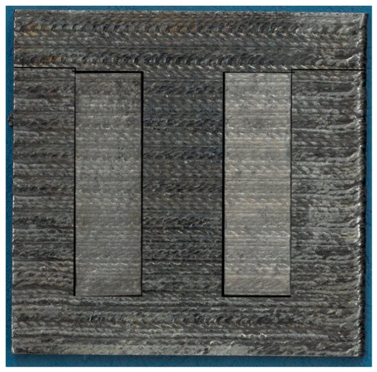
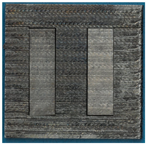
Figure 3 shows a representative surface layer with two coupon-extraction regions. The original deposition tracks remained visible on the exposed coupons, with no gross attack evident at the macroscopic scale. This observation does not exclude localized dissolution or elemental redistribution at the micrometer scale, which were investigated by profilometry and cross-sectional analysis.
Figure 3.
Surface layer from one side of the W-DED MoNiCr cube, showing two coupon-extraction regions and the retained deposition morphology.
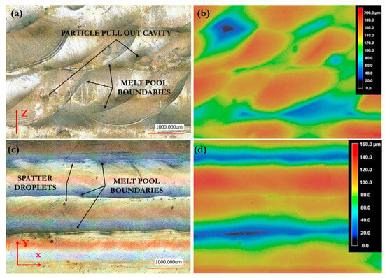
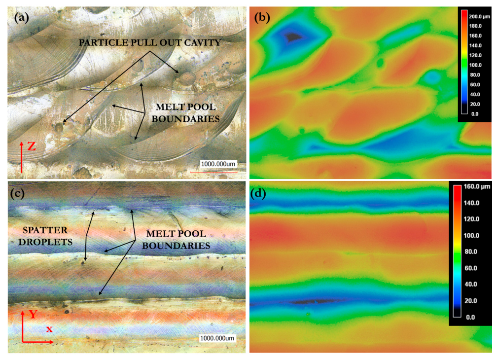
The retained W-DED surfaces showed pronounced orientation-dependent topography (Figure 4). The Z–X and Z–Y surfaces exhibited layer-related ridges, waviness, melt-pool traces, local depressions, and occasional cavities resembling pull-out features. The top X–Y surface was more uniform, although individual deposition tracks remained visible. These macroscopic features remained visible after HIP.
Figure 4.
Representative morphology of unexposed W-DED surfaces and corresponding height maps: a side surface containing the build direction Z (a,b) and the X–Y top surface (c,d). Black arrows identify the features labelled in panels (a,c): a particle pull-out cavity, melt-pool boundaries, and spatter droplets. Red arrows indicate the build direction Z in (a) and the X and Y directions in (c).
3.2. Surface Topography of Exposed and Reference Regions
Table 2 summarizes the topography descriptors for exposed W-DED surfaces and adjacent unexposed reference regions. Differences in the mean values varied in magnitude and direction across orientations and material conditions. For example, mean Rp was higher in the exposed AB X–Y region than in its reference region, whereas the opposite was observed for AB Z–Y. Given the substantial dispersion among the pooled subarea measurements, limited replication, and different measurement coordinates, the data do not distinguish exposure-related changes from pre-existing spatial variability.
These measurements characterize the spatial heterogeneity of the retained deposition surface. Given the limited replication, substantial spatial variability, and different measurement locations, Table 2 does not establish a consistent ranking of AB and HIP material or of the three orientations.
3.3. Microstructure and Local Chemistry
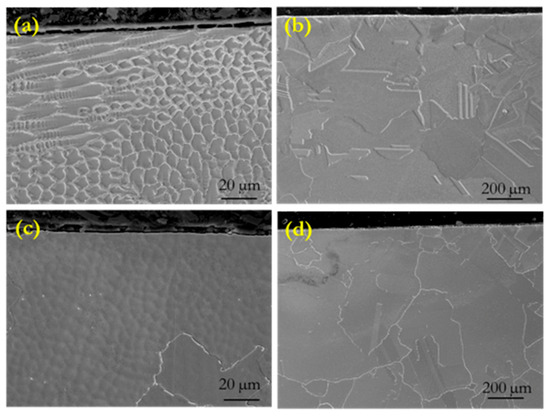
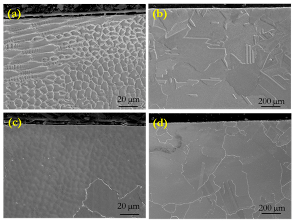
SEM images of etched cross-sections showed distinct microstructural appearances in AB and HIP material (Figure 5). The AB material retained a cellular-dendritic solidification pattern with local segregation and melt-pool-related heterogeneity. The HIP material appeared more homogeneous, with features consistent with recrystallization, although secondary features remained. These observations provide qualitative context for the near-surface corrosion assessment. Detailed characterization of bulk microstructure and mechanical properties is treated separately. The present corrosion dataset does not resolve the individual contributions of porosity, grain structure, segregation, or precipitation to the surface response.
Figure 5.
Representative SEM images of etched cross-sections of MoNiCr: (a) AB, unexposed reference; (b) HIP, unexposed reference; (c) AB, after exposure; and (d) HIP, after exposure. Exposure was to FLiBe at 750 °C for 1000 h. The AB and HIP panels are shown at different magnifications; see the scale bars.
Semiquantitative EDS detected Mo-rich features and local oxygen signals in some cross-sections. Carbon was not quantified, and no X-ray diffraction (XRD), transmission electron microscopy (TEM), or X-ray photoelectron spectroscopy (XPS) data were available for phase identification. An identically cleaned unexposed control was also absent. The features cannot therefore be assigned to a specific carbide, intermetallic compound, oxide, or continuous reaction film. Local oxygen signals may originate from salt exposure, post-test cleaning, specimen preparation, or ex situ handling.
3.4. Near-Surface Elemental Profiles
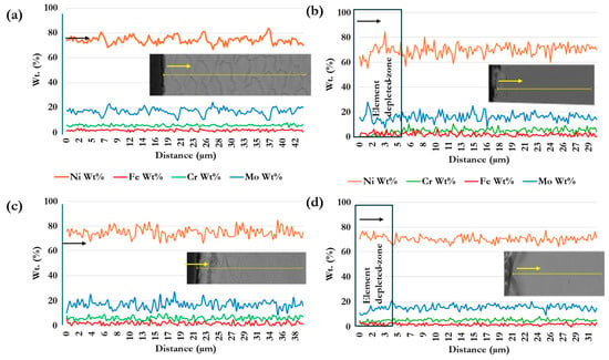
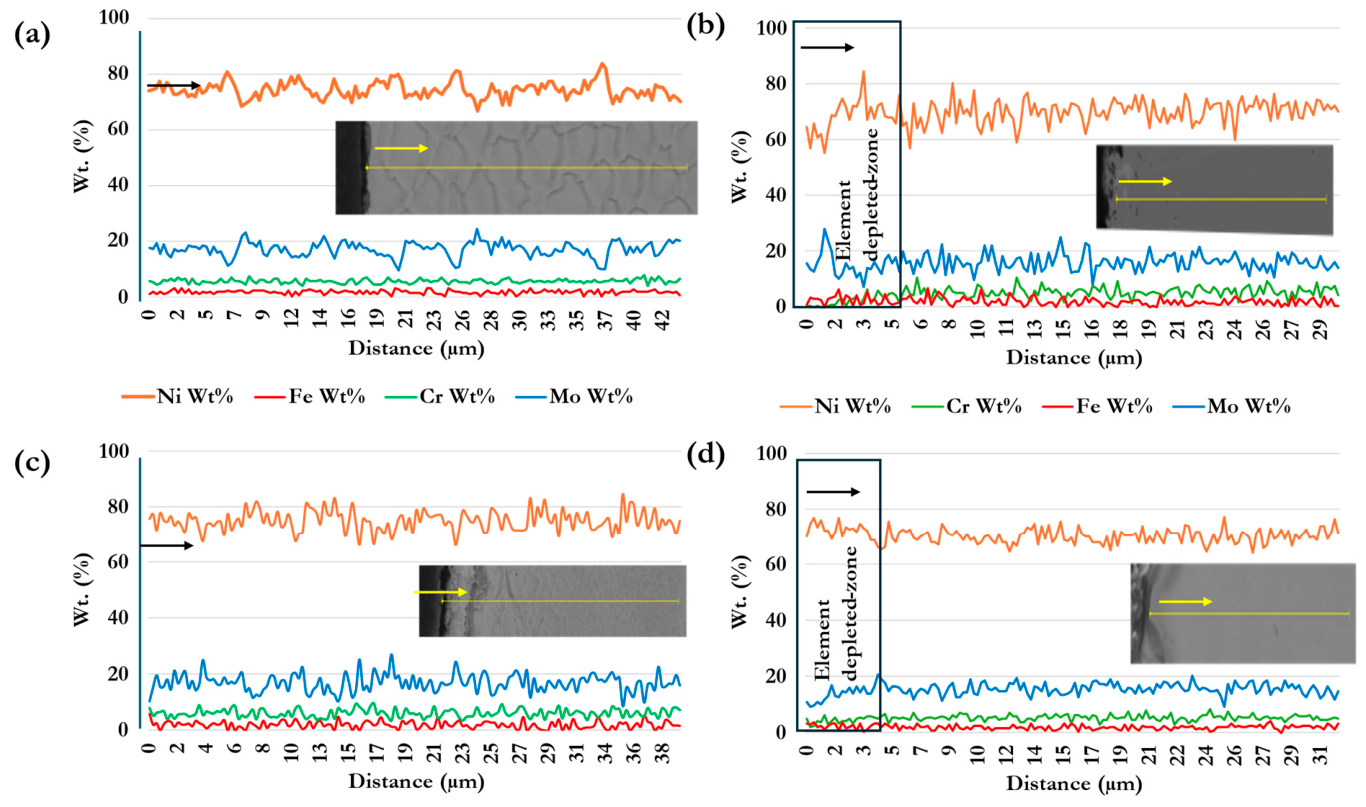
Figure 6 presents EDS line profiles across retained W-DED surfaces. The unexposed reference profiles showed local compositional fluctuations consistent with the heterogeneous deposited microstructure. The exposed profiles showed lower near-surface Cr concentrations, accompanied by relative changes in the other major elements. The semiquantitative profiles support elemental redistribution; the gradual transition toward the bulk prevents assignment of an exact penetration front. Figure 6 retains the distance axes of the original line-profile plots. The effective point spacings estimated from those axes are approximately 0.29 µm point−1 in panel (a) and 0.26 µm point−1 in panel (c); these estimates do not constitute independently verified acquisition settings.
Figure 6.
Representative EDS line profiles across retained W-DED surfaces, acquired on polished cross-sections before etching: (a) AB, unexposed reference; (b) AB, after exposure; (c) HIP, unexposed reference; and (d) HIP, after exposure. Exposure was to FLiBe at 750 °C for 1000 h. The distance axes are retained from the original profile plots. Arrows indicate the scan direction, and boxes highlight the near-surface regions discussed in the text.
BSE images showed a shallow near-surface region with morphology and contrast distinct from the underlying material. This region was identified by examining the cross-section from the original W-DED surface toward the interior. The accompanying EDS profiles indicate elemental redistribution, particularly Cr depletion near the surface. The BSE observations and EDS profiles are complementary and do not provide a statistically supported affected-zone depth or corrosion rate.
Together, the BSE and EDS observations are consistent with selective Cr loss near the surface. The unmeasured salt redox state and impurity concentrations prevent a quantitative assessment of their influence, and the limited replication does not support a kinetic model resolved by orientation or HIP condition.
4. Discussion
4.1. Corrosion of the Retained W-DED Surface
The study documents the response of retained deposition surfaces from a large-format W-DED component to static FLiBe exposure. The original surface remained geometrically heterogeneous after exposure, and cross-sectional observations identified a shallow affected region associated with Cr depletion. These findings are relevant to internal channels and other inaccessible regions where surface finishing may be impractical. A direct comparison of finishing methods would require dedicated polished or machined reference specimens.
Chromium is susceptible to selective dissolution in fluoride salts because soluble chromium fluorides can form under oxidizing conditions [21,22,23,24]. Its removal produces relative enrichment of Ni and Mo near the surface and a concentration gradient that can drive solid-state transport [25]. The present BSE and EDS observations are consistent with coupled selective dissolution and diffusion. However, the observed profile also depends on salt chemistry, containment, specimen cleaning, and how the near-surface region is defined.
Atomistic studies suggest mechanisms that may contribute to this behavior. Chemical ordering can create connected Cr pathways that facilitate near-surface transport and dissolution [26], while grain-boundary environments can strengthen fluorine binding and reduce the barrier to Cr removal [27]. These findings provide possible microstructural explanations, but they do not quantitatively describe the present static exposure.
Preliminary INL observations of as-deposited L-PBF 316H in NaCl–MgCl2 also showed spatially heterogeneous depletion and enrichment on retained manufacturing surfaces [11]. This qualitative similarity supports including such surfaces in corrosion test programs. Differences in alloy, salt, temperature, exposure duration, and redox control prevent direct kinetic comparison.
4.2. Build Orientation and HIP
The variation in topography is consistent with the heterogeneous surface geometry and solidification structure. Layer ridges, overlapping deposition tracks, valleys, and melt-pool boundaries vary with orientation and can affect local salt access and the representativeness of a small profilometry field [5,6,7]. With two coupons per condition and measurements from adjacent reference regions, the contrasting AB X–Y and AB Z–Y results are insufficient to establish an orientation effect.
HIP was associated with visible changes in internal microstructure while leaving the macroscopic deposition relief largely intact. Quantitative characterization of bulk microstructure and mechanical properties is addressed in a separate contribution. The present corrosion observations cannot distinguish the contributions of recrystallization, defect closure, solute homogenization, and secondary-phase evolution.
Microstructure-dependent attack has been reported in specimens from which the original AM surface was removed. Electropolished L-PBF 316L exposed to oxidant-containing FLiNaK showed attack associated with dislocation-cell and boundary structures [14]. Polished wire-arc additively manufactured Hastelloy C276 exhibited pit initiation in interdendritic regions with Cr segregation [17]. These studies motivate quantitative mapping of the relationship between microstructure and attack, but their polished surfaces do not provide a direct comparator for the retained deposition surface examined here.
4.3. Comparison with Previous Ni–Mo–Cr Studies and Relevance to MSRs
The present results cannot be used to rank corrosion resistance against conventionally processed Hastelloy N or alloys tested in previous FLiBe studies. Salt preparation, redox state, impurity concentrations, surface condition, containment, salt-volume-to-specimen-area ratio, cleaning, and the definition of the affected region differ among experiments. The numerical results summarized in the Introduction therefore illustrate sensitivity to test configuration rather than establish a performance benchmark for this study.
Retained manufacturing surfaces and standardized finished surfaces address complementary engineering questions. The present work concerns the former. Future experiments should include ground and polished coupons from the same surface layers, with a defined preparation applied to all immersed faces. Such specimens would allow whole-coupon gravimetry and controlled evaluation of surface preparation.
The wider AM literature also shows that corrosion behavior depends on the specific material and manufacturing route. In chloride salt at 700 °C, laser-deposited 316L and powder-bed-fused Inconel 718 showed alloy-specific responses associated with segregation and phase constitution [15]. In FLiNaK, L-PBF and wrought 316L developed different attack morphologies [16]. Manufacturing route, microstructure, and exposed surface condition must therefore be specified separately.
4.4. Implications for Reproducible Molten-Salt Screening
The 2026 IAEA workshop in Vienna provides context for the need to improve the reproducibility of molten-salt corrosion testing [28]. Relevant variables include salt composition and preparation history, impurity concentrations, redox potential, temperature history, containment materials, exposed area, surface preparation, and post-test cleaning. Glovebox handling and a defined exposure schedule control only part of this experimental variability.
Each coupon was exposed in a separate graphite crucible and sealed AISI 304 enclosure, so coupons did not share a salt bath. The nominal salt volume was 15.51 cm3, with V/A ≈ 0.50 mL cm−2. The finite salt inventory may have allowed dissolved corrosion products to accumulate and the salt composition or redox state to change during the 1000 h exposure. These effects cannot be quantified because the individual charges were not weighed and the salt was not analyzed after exposure. A complete material balance would include the coupon, salt, deposits, graphite crucible, and enclosure. Although characterization was restricted to the W-DED face, the cut faces were also immersed in the same salt charge; their possible contribution to changes in salt chemistry within each capsule cannot be separated.
Static isothermal capsule tests provide initial observations of morphology and elemental redistribution. Assessment for service requires longer exposure series and non-isothermal or flowing-salt experiments that resolve dissolution, deposition, and mass transport [28]. A single 1000 h exposure cannot establish steady-state performance.
4.5. Limitations and Recommended Follow-Up
The main limitations are the single exposure duration, two coupons per orientation and material condition, and the use of adjacent reference regions instead of repeated measurements at identical coordinates. Incomplete profilometry settings and the absence of an inferential statistical design limit quantitative comparisons. Salt redox potential and impurity concentrations were not measured, salt loading was estimated from geometry, and no post-exposure salt analysis or face-specific mass balance was obtained. The cut faces shared the salt charge with the characterized W-DED face. In addition, EDS was semiquantitative; phase identity and oxidation state were not established, and an identically cleaned unexposed control was absent. Consequently, the effects of salt removal and post-exposure cleaning cannot be separated completely from those of the main exposure. These constraints limit the findings to descriptive surface-corrosion screening and preclude quantitative corrosion rates, orientation rankings, or identification of a controlling HIP mechanism.
Further corrosion experiments should use chemically characterized salt with redox monitoring, directly recorded salt masses and exposed areas, and independently replicated coupons under a predefined statistical plan. At least three coupons per condition would improve replication, although the required sample size should be chosen to match the expected variability and effect of interest. Repeated mapping at identical coordinates, specimens with all immersed faces prepared consistently, and ground or polished comparators from the same build would strengthen interpretation. EBSD, quantitative image analysis, XRD or TEM, and XPS on the corrosion coupons or directly matched specimens would help relate local attack to HIP-induced microstructural changes and identify corrosion products.
5. Conclusions
Retained W-DED surfaces extracted from a nominally 100 mm MoNiCr cube were examined after 1000 h of static exposure to FLiBe at 750 °C. The original deposition relief remained macroscopically recognizable in the AB and HIP conditions and across the three orientations examined.
The topography descriptors showed substantial spatial variability and differences in opposite sign between exposed coupons and adjacent unexposed regions. The limited replication and different measurement coordinates prevent separation of exposure-related changes from initial surface heterogeneity and do not support a consistent ranking by orientation or HIP condition.
BSE imaging and semiquantitative EDS indicated a shallow near-surface region associated with Cr depletion. This is a qualitative morphological and compositional finding; a quantitative affected-zone depth or corrosion rate was not established. The microstructural appearance after HIP provides context, but the corrosion observations do not resolve the contributions of grain structure, defect closure, segregation, or precipitation.
Individual capsules prevented salt sharing between coupons, and no external graphite oxidation was observed. Uncharacterized salt chemistry, finite salt inventory, and the absence of a face-specific mass balance restrict interpretation to the tested static conditions.
The findings support including retained deposition surfaces in corrosion screening when component geometry limits access for finishing. Their behavior should be assessed alongside dedicated polished or machined references prepared under controlled conditions.
Material qualification will require a suitable replication and statistical design, measured salt chemistry and redox potential, a complete material balance, and longer exposure series extending to flowing or non-isothermal systems.
Author Contributions
Conceptualization, J.S.; methodology, M.M., M.C., D.B. and Z.F.; validation, M.M., M.C., D.B. and Z.F.; formal analysis, M.M., M.C., D.B. and Z.F.; investigation, M.M., M.C., D.B. and Z.F.; resources, J.S. and D.B.; data curation, M.M., M.C., D.B. and Z.F.; visualization, D.B. and Z.F.; writing—original draft preparation, J.S.; writing—review and editing, J.S., M.M., M.C., D.B. and Z.F.; supervision, J.S.; project administration, J.S. All authors have read and agreed to the published version of the manuscript.
Funding
This research and the article processing charge (APC) were funded by the Ministry of Industry and Trade of the Czech Republic through institutional support provided to Research Centre Řež; no grant or project number was assigned.
Data Availability Statement
The raw data supporting the conclusions of this article will be made available by the authors on request.
Acknowledgments
This work used the CICRR research infrastructure.
Conflicts of Interest
COMTES FHT a.s. produced the MoNiCr alloy, wire feedstock, and W-DED cube under a paid subcontract. The company had no role in the design or conduct of the FLiBe exposure, post-exposure characterization, analysis or interpretation of the corrosion results, preparation of the manuscript, or decision to publish. The authors declare no conflicts of interest. The funder had no role in the study design; collection, analysis, or interpretation of data; preparation of the manuscript; or decision to publish the results.
References
- Serp, J.; Allibert, M.; Beneš, O.; Delpech, S.; Feynberg, O.; Ghetta, V.; Heuer, D.; Holcomb, D.; Ignatiev, V.; Kloosterman, J.L.; et al. The molten salt reactor (MSR) in Generation IV: Overview and perspectives. Prog. Nucl. Energy 2014, 77, 308–319. [Google Scholar] [CrossRef] [Scilit]
- Swindeman, R.W.; Katcher, M.; Ren, W.; Holcomb, D.E. Hastelloy N for molten salt reactors used for power generation. In Proceedings of the ASME 2014 Symposium on Elevated Temperature Application of Materials for Fossil, Nuclear, and Petrochemical Industries, Seattle, WA, USA, 25–27 March 2014. [Google Scholar] [CrossRef] [Scilit]
- Duchek, M.; Nacházelová, D.; Koukolíková, M.; Brázda, M.; Ludvík, P.; Strejcius, J.; Nový, Z. Optimization of MoNiCr alloy production through additive manufacturing. Materials 2025, 18, 42. [Google Scholar] [CrossRef] [Scilit] [PubMed]
- Özel, T.; Shokri, H.; Loizeau, R. A review on wire-fed directed energy deposition based metal additive manufacturing. J. Manuf. Mater. Process. 2023, 7, 45. [Google Scholar] [CrossRef] [Scilit]
- Gorsse, S.; Hutchinson, C.; Gouné, M.; Banerjee, R. Additive manufacturing of metals: A brief review of the characteristic microstructures and properties. Sci. Technol. Adv. Mater. 2017, 18, 584–610. [Google Scholar] [CrossRef] [Scilit] [PubMed]
- Paggetti, S.; Bedogni, E.; Veronesi, P. Factors affecting the surface roughness of the as-built additively manufactured metal parts: A review. Metals 2025, 15, 1069. [Google Scholar] [CrossRef] [Scilit]
- Calvo Correa, M.P.; Cortés Rodríguez, C.J. Analyzing the effects of manufacturing parameters modification on final surface roughness in selective laser melting parts. J. Appl. Eng. Sci. 2024, 22, 707–717. [Google Scholar] [CrossRef] [Scilit]
- Muránsky, O.; Yang, C.; Zhu, H.; Karatchevtseva, I.; Sláma, P.; Nový, Z.; Edwards, L. Molten salt corrosion of Ni–Mo–Cr candidate structural materials for molten salt reactor systems. Corros. Sci. 2019, 159, 108087. [Google Scholar] [CrossRef] [Scilit]
- Danon, A.E.; Muránsky, O.; Karatchevtseva, I.; Zhang, Z.; Li, Z.J.; Scales, N.; Kruzic, J.J.; Edwards, L. Molten salt corrosion (FLiNaK) of a Ni–Mo–Cr alloy and its welds for application in energy-generation and energy-storage systems. Corros. Sci. 2020, 164, 108306. [Google Scholar] [CrossRef] [Scilit]
- Zheng, G.Q.; Kelleher, B.; He, L.; Cao, G.; Anderson, M.; Allen, T.; Sridharan, K. High-temperature corrosion of UNS N10003 in molten Li2BeF4 (FLiBe) salt. Corrosion 2015, 71, 1257–1266. [Google Scholar] [CrossRef] [Scilit] [PubMed]
- Copeland-Johnson, T.M.; Woods, M.E.; Holloway, K.R.; Jokisaari, A.M. Corrosion Testing of Additively Manufactured Stainless Steel 316H in Molten Salt Environments; INL/RPT-24-80816; Idaho National Laboratory: Idaho Falls, ID, USA, 2024. Available online: https://inldigitallibrary.inl.gov/sites/sti/sti/Sort_134953.pdf (accessed on 30 August 2026).
- Abu-Warda, N.; García-Rodríguez, S.; Torres, B.; Utrilla, M.V.; Rams, J. Effect of molten salts composition on the corrosion behavior of additively manufactured 316L stainless steel for concentrating solar power. Metals 2024, 14, 639. [Google Scholar] [CrossRef] [Scilit]
- Lodhi, J.K.; Petersen, C.D.; Macias, D.J.; Matos, M., II; Copeland-Johnson, T.; Pitts, S.; Gakhar, R. Challenges of Additively Manufactured Materials under Molten Salt Corrosion. In Proceedings of the 2026 DOE Molten Salt Reactor Program Review, Albuquerque, NM, USA, 21–24 April 2026; Available online: https://gain.inl.gov/content/uploads/4/2026/05/15-J.Lodhi-hallenges-of-Additively-Mftd-Matierials-Under-Molten-Salt-Corrosion.pdf (accessed on 2 August 2026).
- Ge, Y.; Zhou, W.; Short, M.P.; Que, Z. Mechanisms of molten fluoride salt corrosion of laser powder bed fused 316L stainless steels. npj Mater. Degrad. 2026. [Google Scholar] [CrossRef] [Scilit]
- Shi, H.; Wu, T.; Gong, Q.; Ding, W.; Chai, Y.; Weisenburger, A.; Chang, L.; Zhang, Z.; Wang, K.; Richter, J.; et al. Hot corrosion behavior of additively manufactured stainless steel 316L and Inconel 718 in MgCl2/KCl/NaCl chloride salts at 700 °C. Corros. Sci. 2022, 207, 110561. [Google Scholar] [CrossRef] [Scilit]
- Salbæk, M.; Jensenius Schollert, O.; Bredahl Gjelsten, X.; Juul Jensen, D.; Barode, J.; Jellesen, M.; Hald, J.; Just Sørensen, T. Comparative corrosion performance of additively and conventionally manufactured AISI 316L stainless steel in molten FLiNaK salt at 700 °C. IOP Conf. Ser. Mater. Sci. Eng. 2025, 1332, 012019. [Google Scholar] [CrossRef] [Scilit]
- Zhu, H.; Qiu, Z.; Wang, Z.; Muránsky, O.; Wei, T.; Karatchevtseva, I.; Davis, J.; Li, H. Chromium depletion and microstructural effects on molten salt corrosion of wrought and wire-arc additively manufactured Hastelloy C276 alloys. Corros. Sci. 2026, 264, 113733. [Google Scholar] [CrossRef] [Scilit]
- Jokisaari, A.M.; Chen, Y.; Copeland-Johnson, T.; Hartmann, T.; Joshi, V.; van Rooyen, I.; Song, R.; Wierschke, J. Corrosion testing needs and considerations for additively manufactured materials in nuclear reactors. Prog. Nucl. Energy 2024, 174, 105296. [Google Scholar] [CrossRef] [Scilit]
- Cantor, S. Density and Viscosity of Several Molten Fluoride Mixtures; ORNL-TM-4308; Oak Ridge National Laboratory: Oak Ridge, TN, USA, 1973; pp. 1–13. [Google Scholar] [CrossRef] [Scilit]
- Research Centre Řež. Prototype Ampoule for Exposure Corrosion Tests in Molten Salts, Technical Report PL 6068, version 0; Research Centre Řež: Husinec-Řež, Czech Republic, 2026. [Google Scholar]
- Wang, Y.L.; Wang, Q.; Liu, H.J.; Zeng, C.L. Effects of the oxidants H2O and CrF3 on the corrosion of pure metals in molten (Li,Na,K)F. Corros. Sci. 2016, 103, 268–282. [Google Scholar] [CrossRef] [Scilit]
- Chan, H.L.; Romanovskaia, E.; Qiu, J.; Hosemann, P.; Scully, J.R. Insights on the corrosion thermodynamics of chromium in molten LiF–NaF–KF salts. npj Mater. Degrad. 2022, 6, 46. [Google Scholar] [CrossRef] [Scilit]
- Zheng, G.Q.; Sridharan, K. Corrosion of structural alloys in high-temperature molten fluoride salts for applications in molten salt reactors. JOM 2018, 70, 1535–1541. [Google Scholar] [CrossRef] [Scilit]
- Fulín, Z.; Strejcius, J.; Špirit, Z. Corrosion of Inconel 800HT alloy in molten fluoride salts. Manuf. Technol. 2024, 24, 755–764. [Google Scholar] [CrossRef] [Scilit]
- Mills, S.H.; Hayes, R.D.; Bieberdorf, N.; Zeltmann, S.E.; Kennedy, A.M.; Capolungo, L.; Asta, M.; Scarlat, R.O.; Minor, A.M. Elucidating the role of Cr migration in Ni–Cr exposed to molten FLiNaK via multiscale characterization. Acta Mater. 2024, 279, 120206. [Google Scholar] [CrossRef] [Scilit]
- Arkoub, H.; Ke, J.-H.; Bawane, K.; Jin, M. Percolating corrosion pathways of chemically ordered NiCr alloys in molten salts. Corros. Sci. 2026, 269, 113960. [Google Scholar] [CrossRef] [Scilit]
- Arkoub, H.; Jin, M. First-principles investigation of grain-boundary effects on fluorine-induced initial corrosion of NiCr alloys. Comput. Mater. Sci. 2025, 255, 113903. [Google Scholar] [CrossRef] [Scilit]
- International Atomic Energy Agency. Workshop on the Current Status of Structural Material Development for Molten Salt Reactors and Related Challenges; International Atomic Energy Agency: Vienna, Austria, 2026; Available online: https://conferences.iaea.org/event/466/ (accessed on 30 August 2026).

Disclaimer/Publisher’s Note: The statements, opinions and data contained in all publications are solely those of the individual author(s) and contributor(s) and not of MDPI and/or the editor(s). MDPI and/or the editor(s) disclaim responsibility for any injury to people or property resulting from any ideas, methods, instructions or products referred to in the content. |
© 2026 by the authors. Licensee MDPI, Basel, Switzerland. This article is an open access article distributed under the terms and conditions of the Creative Commons Attribution (CC BY) license.