


Abstract
Hybrid machining combining laser and mechanical processes has attracted increasing attention for improving the machining efficiency of hard-to-cut materials. In this study, a sequential hybrid machining concept is proposed in which nanosecond-pulsed laser milling is used for rough material removal before mechanical machining. First, the effects of laser-processing conditions on material removal and surface morphology were investigated to identify suitable rough-machining conditions. Based on these results, the proposed sequence, in which laser milling removes bulk material followed by mechanical machining for dimensional correction and surface finishing, was evaluated using computer-aided manufacturing (CAM)-based machining-time estimation. The proposed hybrid strategy was compared with conventional machining using mechanical cutting alone. The CAM analysis estimated machining-time reductions of approximately 44% for an idealized case without laser-induced taper and 36% when the experimentally observed taper was incorporated into the model. These results indicate the potential of nanosecond-pulsed laser milling as a rough-machining process for cemented-carbide die and mold manufacturing, while subsequent mechanical machining is required to compensate for surface and geometric limitations.
1. Introduction
Cemented carbides are widely used for precision dies, molds, cutting tools, and wear-resistant components because of their high hardness, wear resistance, and dimensional stability. They consist primarily of hard tungsten carbide (WC) grains bonded by a metallic binder, typically cobalt (Co) [1,2]. However, these properties also make cemented carbides difficult to machine by conventional mechanical processes, particularly when using small-diameter tools, which are susceptible to severe wear and reduced machining efficiency [3,4,5,6,7]. Although polycrystalline diamond (PCD) and diamond-coated tools have been employed for precision machining, tool wear and other machining limitations remain significant challenges [3,4,5,6,7]. Therefore, an efficient rough-machining process capable of removing a large volume of cemented carbide before subsequent precision machining is desirable.
Laser processing is promising for machining hard materials because material can be removed without direct mechanical contact. Laser processing of cemented carbide has been investigated using various pulse durations and wavelengths [8,9,10,11]. Pulsed UV lasers have been used to investigate WC–Co ablation and selective removal of the Co binder [9,10], whereas ultrashort-pulse lasers have been studied for precision processing with reduced thermal effects [11]. In contrast, nanosecond laser processing can induce melting, evaporation, and resolidification, leading to surface irregularities, oxidation, and cracking [8,12,13,14,15]. See et al. reported crack formation during nanosecond UV laser ablation of WC–Co [13], while Chu et al. demonstrated melting, evaporation, and phase explosion during nanosecond UV laser processing of WC–8Co [14]. Zhang et al. further showed that thermal stress during nanosecond laser processing can cause severe cracking and subsurface damage [15]. These thermal effects and the resulting damage must therefore be considered when applying nanosecond laser processing to cemented carbide. The choice of pulse duration involves a trade-off between material-removal efficiency and thermal damage. Millisecond- and microsecond-duration lasers generally provide high thermal input but tend to produce larger heat-affected regions and resolidified material, whereas picosecond- and femtosecond-pulse lasers can suppress thermal effects and improve processing precision at the expense of higher system cost and potentially lower material-removal throughput. Nanosecond lasers provide an intermediate regime in which relatively high material-removal rates can be achieved with commercially available and comparatively robust laser systems, although thermal effects such as melting, resolidification, oxidation, and cracking remain significant. For the present study, nanosecond laser processing was therefore selected because the objective was not precision finishing but efficient bulk material removal prior to mechanical finishing.
The laser response of cemented carbide also depends on its composition and microstructure. Under certain pulsed-UV-laser conditions, the Co binder can be preferentially removed [9,10], and differences among WC–Co grades have been reported to affect laser-ablation behavior [13]. Fang et al. investigated the effects of cemented-carbide composition on surface and mechanical integrity following nanosecond laser ablation [16]. In addition, laser surface texturing and subsequent surface treatments of cemented carbide have been investigated [17,18,19]. However, the effects of Co content and WC grain size on material removal during nanosecond laser milling, particularly for rough machining, remain insufficiently understood.
For die and mold fabrication, cavity geometry is another important consideration. Previous studies have mainly focused on laser ablation of spots, grooves, and surface textures [11,13,17,18,19]. However, in relatively deep three-dimensional cavities, changes in beam diameter and power-density distribution with increasing distance from the focal plane can result in nonuniform material removal and deviations from the intended geometry. Consequently, nanosecond laser milling may be more suitable for rough machining than for replacing mechanical machining. Laser-based hybrid machining has therefore been investigated to combine the high material-removal capability of laser processing with the dimensional accuracy and surface quality achievable by conventional machining [20]. Recent studies have examined laser-assisted and other energy-assisted machining approaches for difficult-to-cut materials, focusing on improved machinability, reduced cutting forces, and enhanced tool life [21,22,23]. In particular, laser-assisted milling has been investigated with respect to the optimization of laser-tool distance and laser power [22], while laser-assisted hybrid machining of cemented carbide has also been studied to improve machining performance [23]. These studies demonstrate the potential of laser-based hybrid machining; however, most employ the laser primarily to assist the mechanical cutting process rather than to remove a substantial volume of material before subsequent machining. In the present study, laser milling is used for bulk material removal, followed by mechanical machining for dimensional correction and surface finishing.
However, the applicability of nanosecond laser milling as a rough-machining process for cemented-carbide die cavities, including the effects of material grade, cavity geometry, and the machining allowance required for subsequent mechanical finishing, has not been sufficiently investigated. In particular, the relationships among laser-milling efficiency, material-dependent removal behavior, cavity taper, and subsequent machining strategy remain unclear. The necessity of the present study arises from the mismatch between the advantages and limitations of laser milling for cemented-carbide die machining. Laser processing can remove material without tool–workpiece contact and can therefore reduce the mechanical cutting load, whereas its thermal effects and depth-dependent geometric deviations make it unsuitable for final precision machining. The originality of this study lies not in applying a laser to cemented carbide itself, but in systematically evaluating nanosecond laser milling from the viewpoint of its function as a rough-machining step and in linking laser-material interaction, material-dependent removal behavior, cavity taper, and the machining requirements of the subsequent mechanical process.
The effects of average laser power and overlap ratio on material removal and surface characteristics are first investigated. The morphology and composition of the resolidified material are then examined, followed by evaluation of the effects of Co content and WC grain size on material removal. The cross-sectional geometry of laser-milled cavities is also evaluated. Finally, a sequential hybrid machining concept is assessed using computer-aided manufacturing (CAM)-based machining-time estimation and compared with conventional mechanical machining.
2. Experimental Methods
2.1. Workpiece Material
The workpieces were WC–Co cemented carbides used for precision die and mold applications. The cemented-carbide grades were supplied by Kyoritsu Gokin Co., Ltd. (Nishinomiya, Japan). As shown in Table 1, three commercially available WC–Co cemented-carbide grades with different Co contents and WC grain sizes were used to investigate the effects of material composition and microstructure on laser milling. The material properties listed in Table 1, including Co content, WC grain size, hardness, density, and thermal conductivity, were obtained from the manufacturer’s catalog data. VF-10 was primarily used to evaluate the laser-milling characteristics of cemented carbide. The workpiece dimensions were 50 mm × 50 mm × 5 mm, and 50 × 50 mm2 surfaces were ground and finished. The initial arithmetic mean surface roughness, Ra, of the ground surface was approximately 0.3 μm.
Table 1.
Properties of the cemented-carbide grades used in this study. The listed properties were obtained from the manufacturer’s catalog data.
2.2. Laser-Processing Experiment
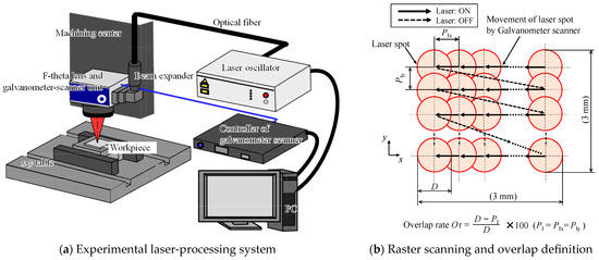
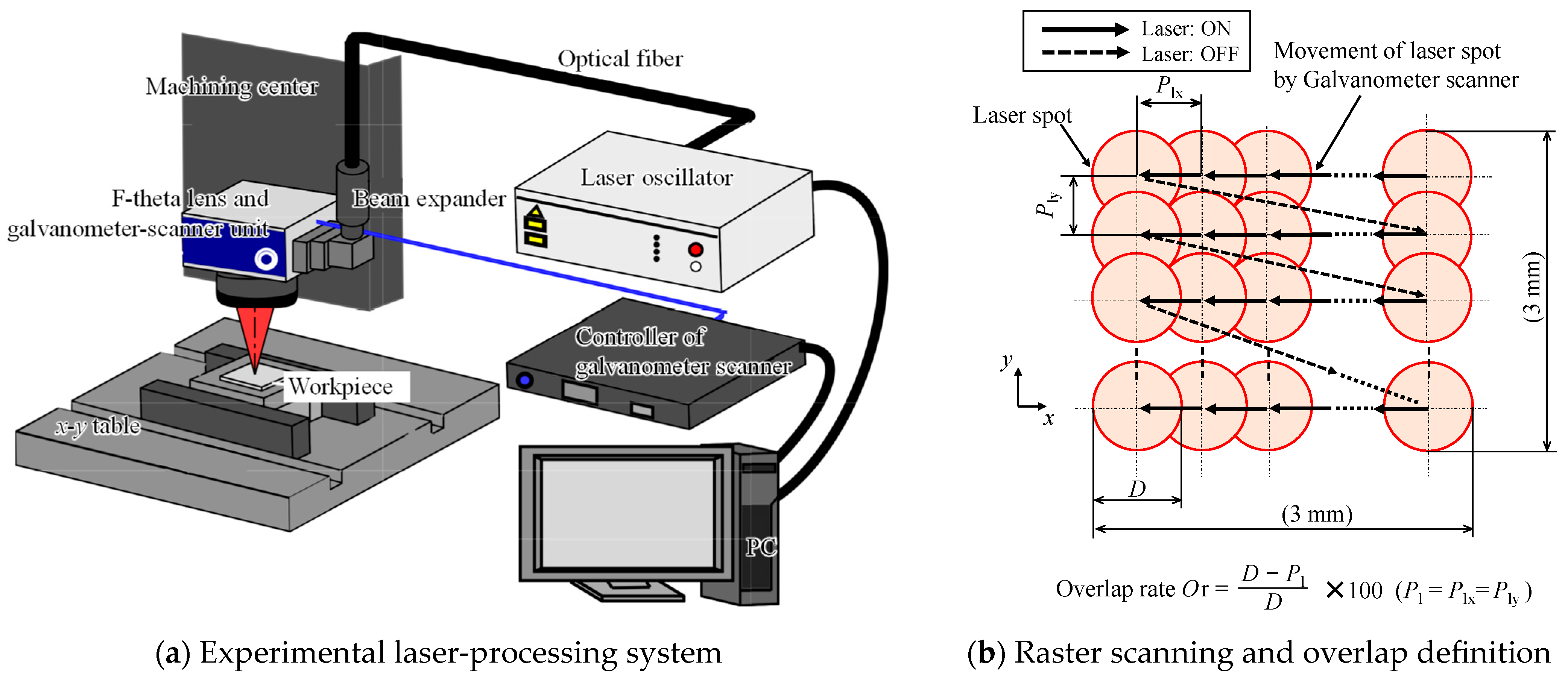
The laser milling experiments were performed using a nanosecond-pulsed fiber laser system equipped with a galvanometer scanner, as shown in Figure 1. The laser source was a YLP-HP-10-A30-20-200 (IPG Photonics Corp., Marlborough, MA, USA). The laser beam was transmitted through an optical fiber and focused onto the workpiece using an F-theta lens and a galvanometer-scanner optical system (ARGES GmbH, Wackersdorf, Germany). The laser-processing conditions are listed in Table 2. The laser wavelength λ, pulse frequency F, pulse duration Td, and spot diameter D were fixed at 1064 nm, 20 kHz, 60 ns, and approximately 77 μm, respectively. The spot diameter was theoretically estimated from D = 4fλM2/(πDb), where f is the focal length, λ is the laser wavelength, M2 is the beam quality factor, and Db is the incident beam diameter at the focusing lens. Using f = 99.3 mm, λ = 1064 nm, M2 = 2, and Db = 3.5 mm, the calculated spot diameter was approximately 77 μm. The corresponding Rayleigh length was estimated as zR = π(D/2)2/(M2λ), giving approximately 2.2 mm. Since the maximum nominal laser-milling depth considered in this study was approximately 0.2 mm, the entire machined depth was within the calculated Rayleigh length. The laser beam was repeatedly raster-scanned over a 3 × 3 mm2 area to form a series of spots, as shown in Figure 1. The overlap ratio, Or, was defined as Or = (D − Pl)/D × 100, where D is the laser spot diameter and Pl is the distance between adjacent laser spots. The same overlap ratio was applied in both the x- and y-scanning directions, as shown in Figure 1, with linear scanning performed in the x direction. The defocusing distance at the start of irradiation was set to zero, and the initial focal position was fixed throughout the experiments. The average laser power, Pave, corresponding pulse energy, Ep, overlap ratio, Or, and number of raster-scanning cycles, N, were varied. The pulse energy was calculated from Ep = Pave/f, where f is the pulse repetition frequency. The average-power range was selected to include conditions below and above the experimentally observed onset of measurable material removal. The three overlap ratios represented low, intermediate, and high pulse superposition, enabling comparison of spot-dominated removal, relatively stable milling, and heat-accumulation-dominated surface formation.
Figure 1.
Schematics of experimental equipment and raster scanning laser irradiation.
Table 2.
Laser-processing conditions.
2.3. Evaluation
The depth removal rate, vd, was defined as the machined depth, dh, divided by the laser irradiation time, T. The machined depth, dh, was measured using a digital indicator. The laser irradiation time, T, was defined as the elapsed processing time required to complete the specified number of raster-scanning cycles. The surface morphology of the laser-irradiated area was examined using an optical microscope and a scanning electron microscope (SEM; JSM-6010LA, JEOL, Akishima, Japan). SEM observations were performed at an accelerating voltage of 20.0 kV, a working distance of approximately 10 mm, and a magnification of 1000×. The arithmetic surface roughness at the center of the laser-irradiated area was measured using a tactile computer numerical control surface-roughness and contour-measuring machine (CS-H5000CNC, Mitutoyo, Kawasaki, Japan). The cross-sectional profile of the laser-irradiated area was also measured using the same machine. The elemental composition of the resolidified deposits formed was analyzed using an energy-dispersive X-ray spectroscopy (EDS) system (JED-2300F, JEOL, Akishima, Japan) equipped with a silicon drift detector (SDD; JED-2300F, JEOL, Akishima, Japan). EDS spectra were acquired using a live time of approximately 3096 s. The SEM and EDS operating conditions were specified above based on the available measurement records.
3. Results and Discussion
3.1. Selection of Laser-Milling Conditions
3.1.1. Effect of Average Laser Power
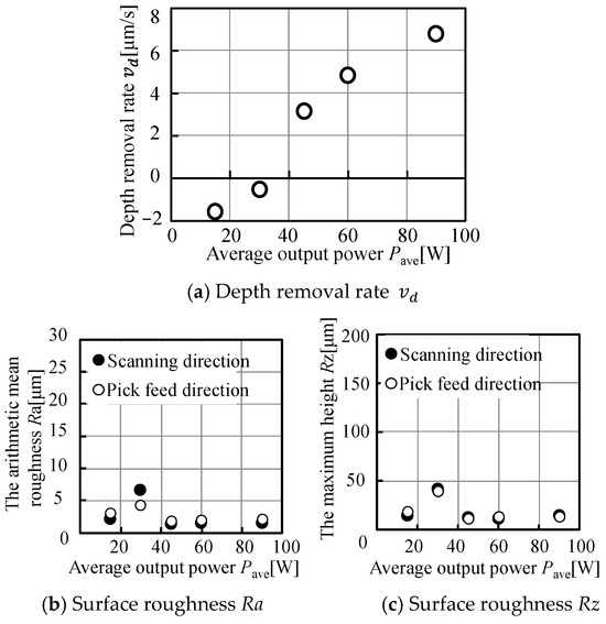
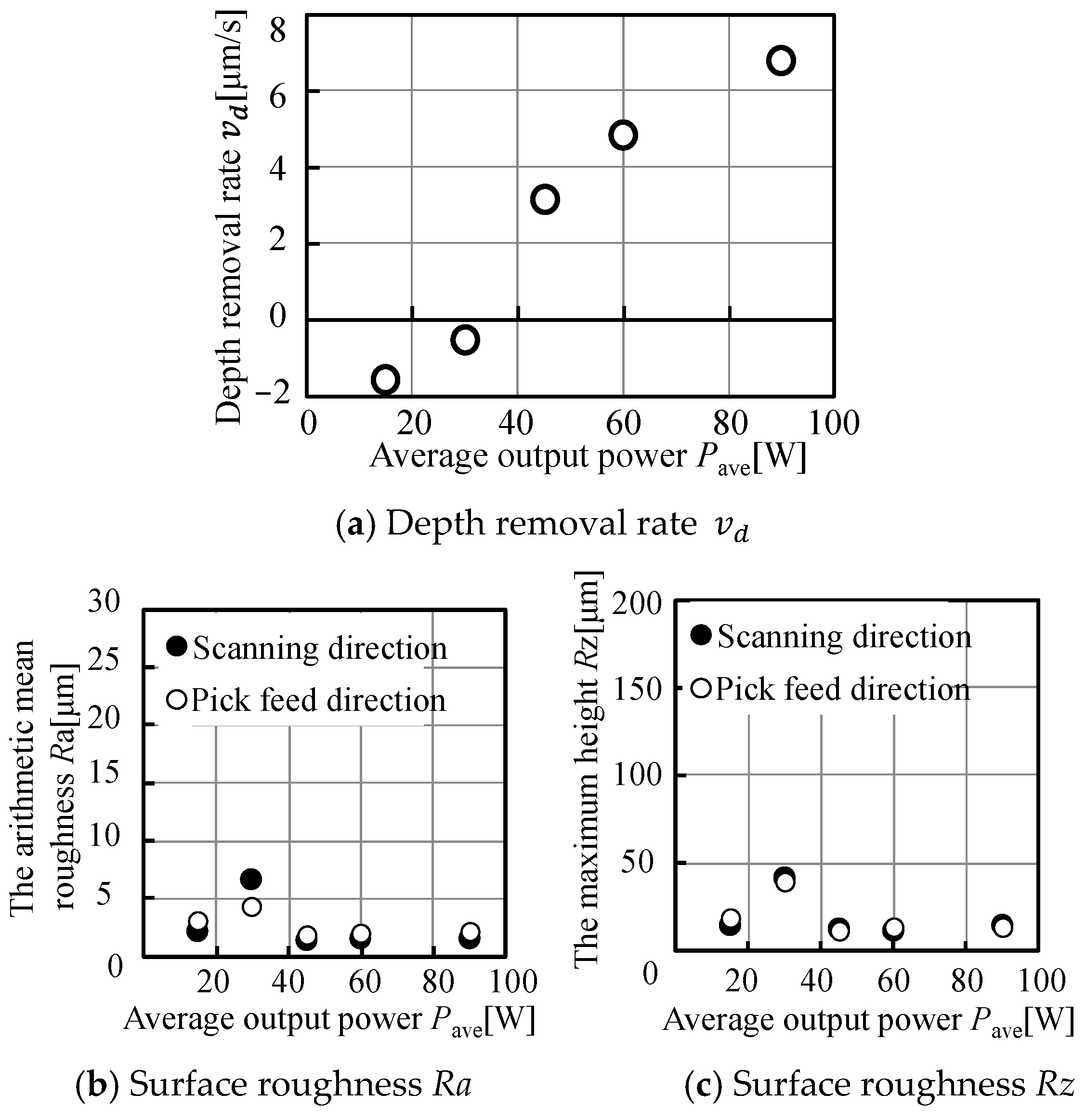
Figure 2 shows the effect of average laser power on the machining characteristics of the cemented carbide. At 15 and 30 W, no measurable material removal was observed even after 20 irradiation cycles. Under these conditions, the measured surface was slightly higher than the initial surface, resulting in negative vd values. This apparent increase in surface height is attributed primarily to thermal expansion of the cemented carbide during laser irradiation, although contributions from surface modification and redeposition cannot be completely excluded [8,12,13,14,15]. In contrast, material removal was observed at 45 W and above, and the machining depth increased with increasing average laser power. After 20 irradiation cycles, the machining depths at 45, 60, and 90 W were approximately 72, 111, and 156 μm, respectively. The vd value also increased with average laser power over this range. Higher laser power, however, did not necessarily result in greater surface roughness under the present conditions. At sufficiently high power, increased material removal can be accompanied by enhanced melting and redeposition, which may increase surface irregularity; however, this effect was not sufficiently systematic over the investigated power range to produce a monotonic increase in Ra. As shown in Figure 2, the surface roughness did not increase systematically with average laser power under conditions where effective material removal occurred. In particular, the surface roughness remained within a comparable range at 45–90 W, despite the increase in vd with increasing power. Although 90 W provided the highest vd, 60 W was selected as a representative moderate-power condition because it provided effective material removal while maintaining relatively low surface roughness. Therefore, 60 W was used as the reference average laser power for subsequent experiments. The relatively high surface roughness observed at higher laser power can be attributed to the increased energy input per pulse, which promotes more extensive melting and subsequent resolidification of the irradiated material. The formation and redeposition of molten material can increase local surface irregularities, particularly under conditions where the supplied energy exceeds that required for stable material removal.
Figure 2.
Effect of average laser power on machining characteristics after 20 raster-scanning cycles at an overlap ratio of 60% for VF-10 cemented carbide material.
3.1.2. Effect of Overlap Ratio
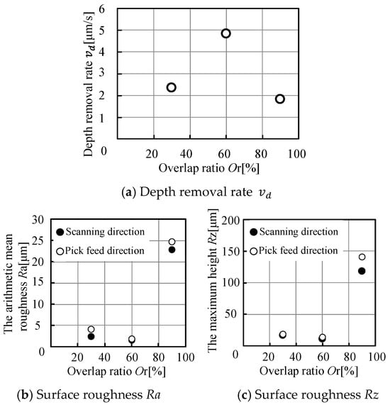
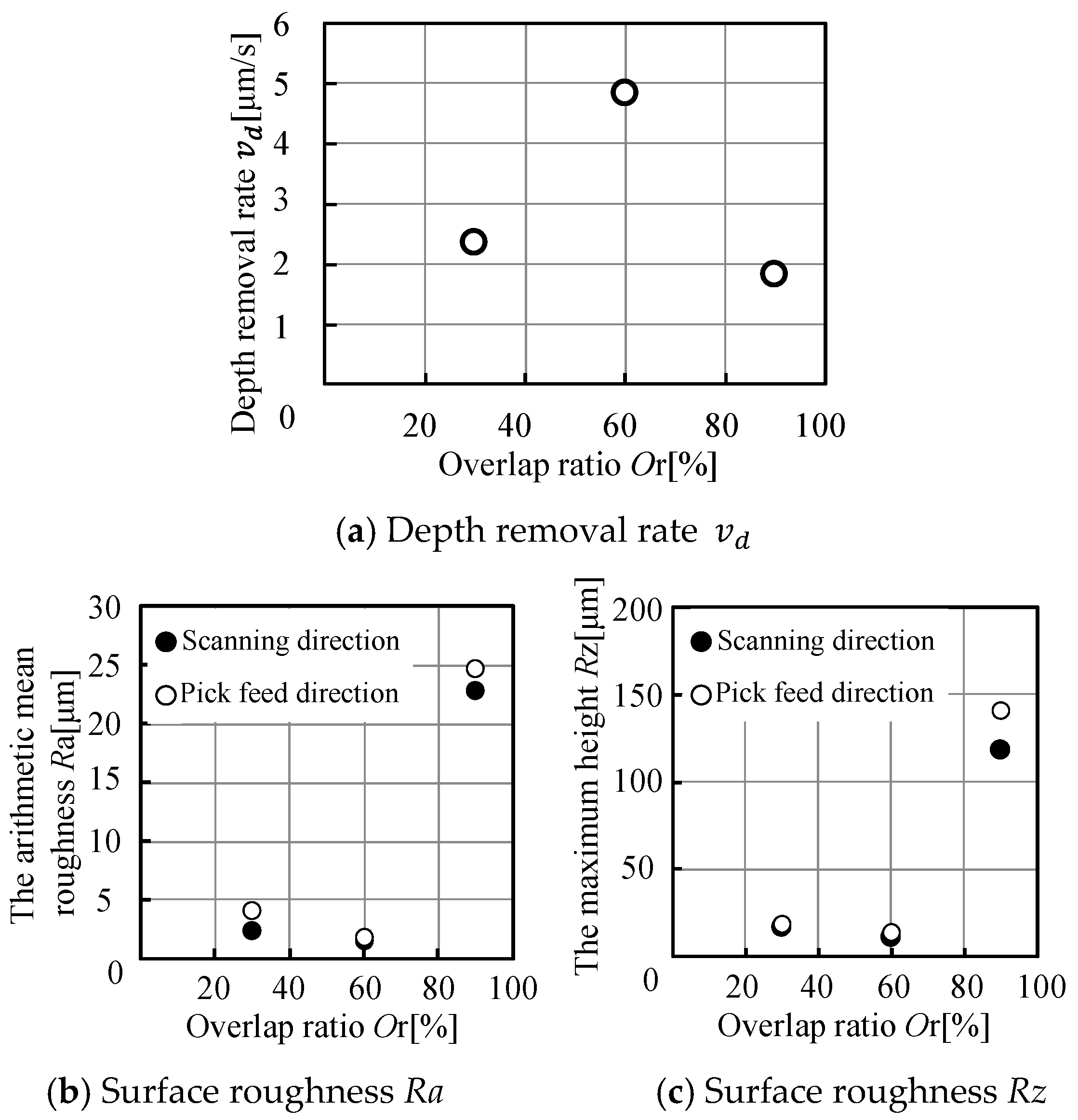
Having established a suitable laser power for rough machining, the effect of overlap ratio was subsequently investigated because it controls the degree of spatial overlap between successive laser pulses within the irradiated area. Figure 3 shows the surface roughness and vd obtained at overlap ratios of 30%, 60%, and 90%. The vd values did not increase monotonically with overlap ratio. The highest vd was obtained at an overlap ratio of 60%, whereas it decreased substantially at 90%. At the same time, the surface roughness was lowest at 60%, whereas a marked increase in roughness was observed at 90%. These results suggest that increasing the overlap ratio up to 60% improves material-removal efficiency, whereas excessive overlap does not necessarily improve rough-machining efficiency because the removal rate decreases and surface roughness deteriorates. The decrease in vd at 90% overlap may be partly associated with increased plasma and vapor generation under repeated irradiation, which can shield subsequent laser pulses and reduce the effective energy delivered to the workpiece. However, plasma shielding was not directly measured in the present study and is therefore considered a possible contributing mechanism rather than a demonstrated cause. Therefore, an overlap ratio of 60% was selected as the reference condition for subsequent experiments because it provided the highest vd and relatively low surface roughness among the investigated conditions.
Figure 3.
Effect of overlap ratio on machining characteristics after 20 raster-scanning cycles at an average laser power of 60 W for VF-10 cemented carbide.
3.2. Surface Formation and Material-Removal Behavior
3.2.1. Surface Morphology at Different Overlap Ratios
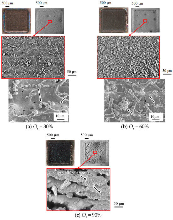
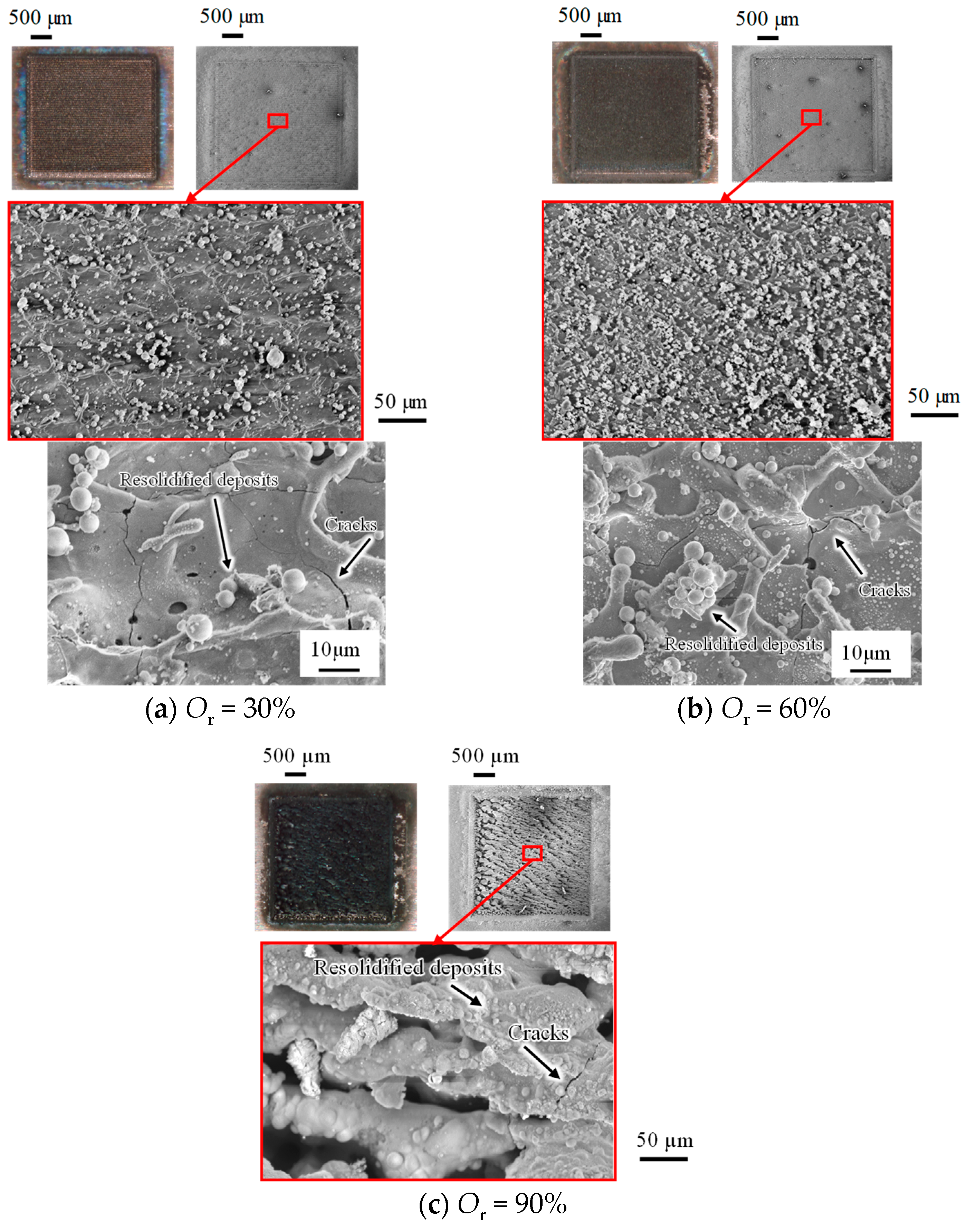
The surface morphology at different overlap ratios was examined to clarify the characteristics of the laser-milled surfaces. Figure 4 shows optical and SEM images of the laser-milled surfaces obtained at overlap ratios of 30%, 60%, and 90% after 20 raster-scanning cycles. At 30% overlap, periodic surface undulations corresponding approximately to the laser spot spacing were observed. In contrast, the surface obtained at 60% overlap was comparatively uniform, and the periodic undulations associated with individual laser spots were less prominent. At 90% overlap, relatively large irregularities and deposits of resolidified material were observed over the irradiated area. These differences in surface morphology can be interpreted in terms of the irradiation conditions. At low overlap, the relatively large spacing between adjacent laser spots resulted in periodic irradiation marks. As the overlap ratio increased, the crests of adjacent laser-induced dimples increasingly overlapped, making the individual spot-related undulations less distinguishable and producing a comparatively uniform surface. At excessive overlap, however, increased heat accumulation may have promoted melting and subsequent redeposition, resulting in larger surface irregularities and resolidified deposits, particularly at 90% overlap. Although the surface at 60% overlap was comparatively uniform, resolidified material and cracks were still observed. Resolidified deposits and cracks were identifiable in the SEM images for all overlap conditions. At 90% overlap, the surface exhibited particularly pronounced irregularities and resolidified deposits. Because the surface topography at 90% overlap was highly irregular, higher-magnification imaging did not provide additional useful morphological information for the present comparison. These cracks may be associated with thermal stresses generated by rapid heating and cooling during nanosecond laser irradiation, potentially coupled with the effects of laser-induced plasma. However, the present study did not directly characterize the transient thermal stress or plasma behavior, and therefore the specific crack-formation mechanism cannot be conclusively determined. Therefore, the laser-milled surface was not suitable for final finishing and should instead be regarded as a rough-machined surface requiring subsequent mechanical machining. However, SEM observations alone cannot determine the composition or origin of the deposited material.
Figure 4.
Optical microscopy and SEM observations of laser-milled surfaces of VF-10 cemented carbide at different overlap ratios (Pave = 60 W, N = 20 raster-scanning cycles, f = 20 kHz, D = 77 μm, Td = 60 ns).
3.2.2. Composition of Resolidified Deposits
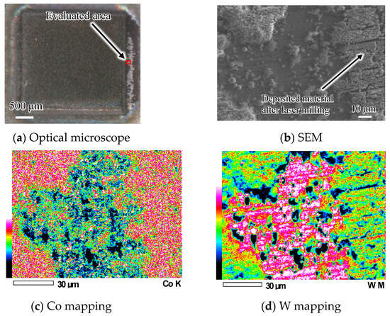
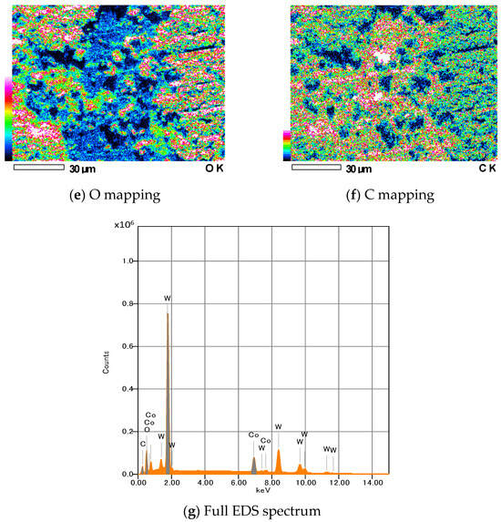
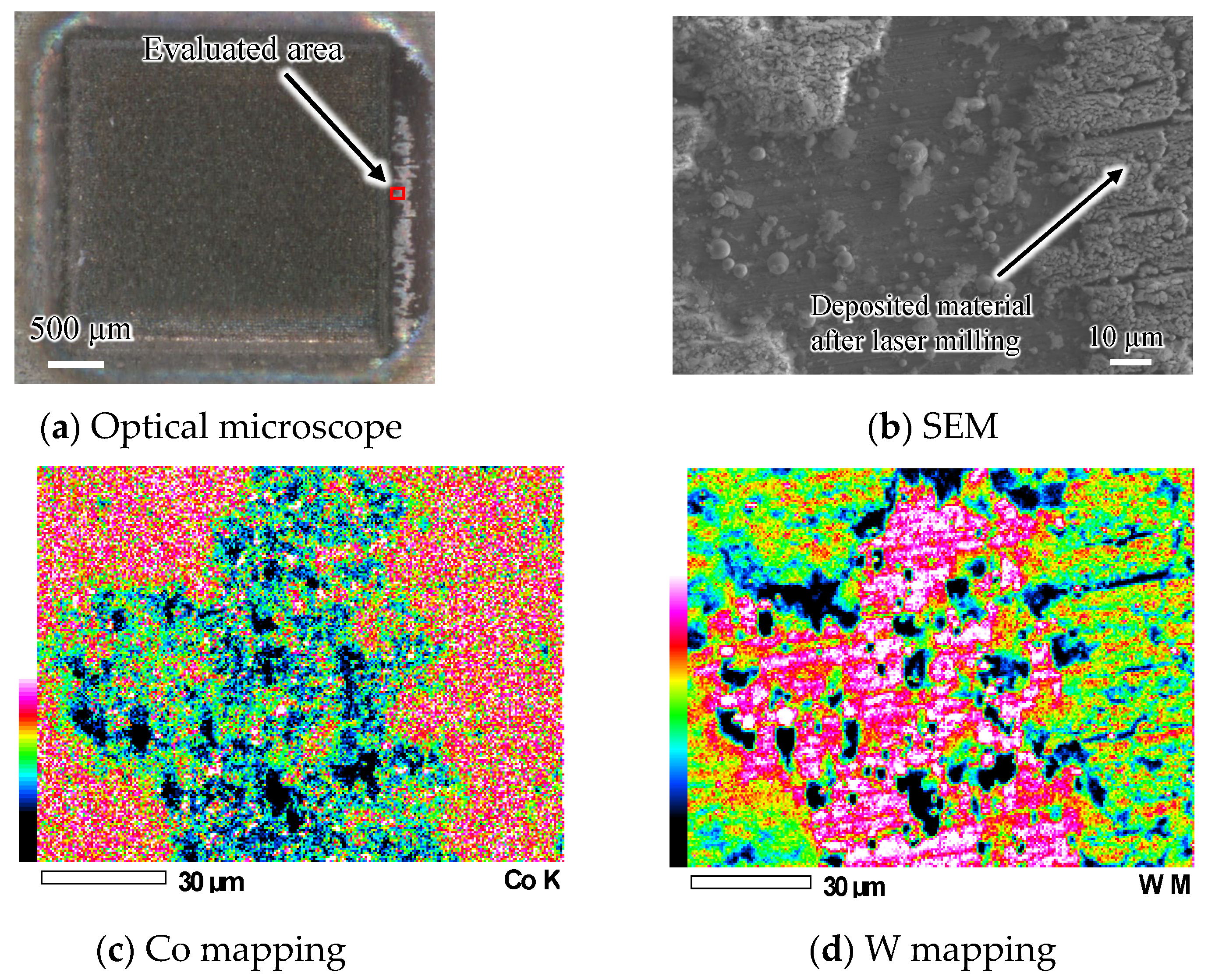
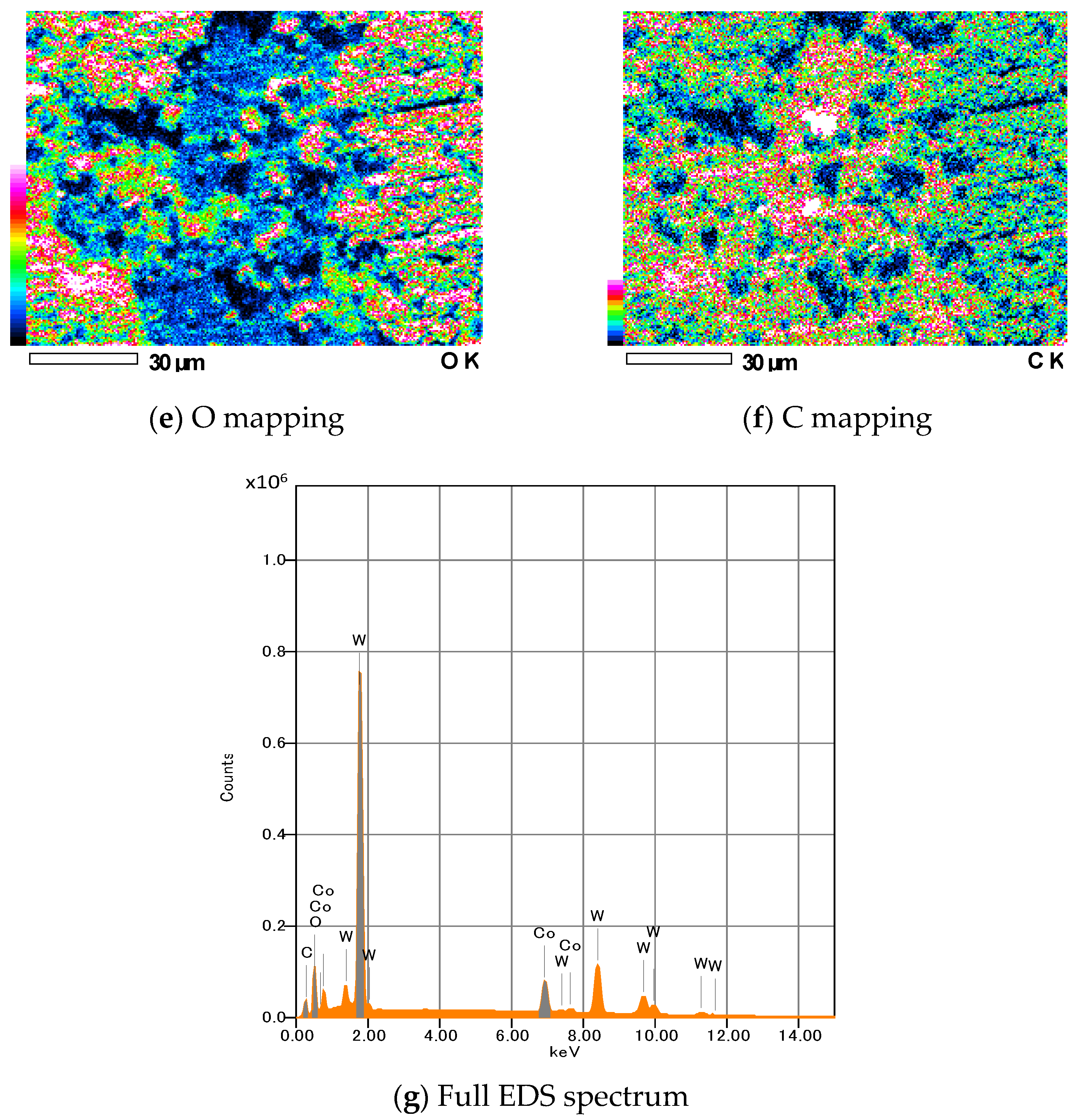
Figure 5 shows the EDS results for the resolidified deposits. Oxygen was detected in the deposits, indicating the presence of oxygen-containing material. Because the laser processing was performed in air, the detected oxygen may have resulted from thermal oxidation of the molten or resolidified material during and after laser irradiation. In addition, the deposited region exhibited relatively lower W and C contents and a higher Co content than the base material. These results indicate that Co-containing material was present in the redeposited region and that oxidation occurred during laser processing. Cemented carbide consists primarily of WC grains and a Co binder, with the melting points of Co and WC being approximately 1495 and 2870 °C, respectively [24]. The relatively higher Co content detected in the resolidified deposits suggests that the Co-containing phase may have contributed to laser-induced melting and subsequent redeposition [24]. This interpretation is consistent with the higher material-removal rate observed for the cemented carbide with higher Co content, as discussed in Section 3.3. However, the EDS results should not be interpreted as direct evidence of preferential Co removal from the cemented carbide. Because EDS was performed on the redeposited material, the measured elemental composition represents the analyzed deposit and may have been affected by melting, redistribution, and redeposition during laser processing. Therefore, the present results indicate that Co-containing material was involved in the laser-induced melting and redeposition process, but they do not conclusively establish preferential removal of individual constituents. These observations suggest that Co content may affect the laser-milling behavior of cemented carbide. To examine this possibility, the laser-milling characteristics of cemented carbides with different Co contents were subsequently investigated.
Figure 5.
EDS analysis of the resolidified deposits around the laser-milled area of VF-10 cemented carbide: (a) optical microscopy image, (b) SEM image, (c) Co elemental mapping, (d) W elemental mapping, (e) O elemental mapping, (f) C elemental mapping, and (g) full EDS spectrum , where the orange trace represents the measured EDS spectrum and the gray regions indicate the identified elemental peaks. (Pave = 60 W, Or = 60%, N = 20 raster-scanning cycles, f = 20 kHz, D = 77 μm, Td = 60 ns).
3.3. Effect of Cemented-Carbide Composition and Microstructure
The results presented in the previous section suggest that melting and redeposition of Co-containing material may contribute to material removal during nanosecond laser milling. Therefore, the laser-milling characteristics may depend on the composition and microstructure of the cemented carbide. The effects of Co content and WC grain size on the machining characteristics were consequently investigated.
3.3.1. Effect of Co Content
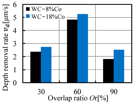
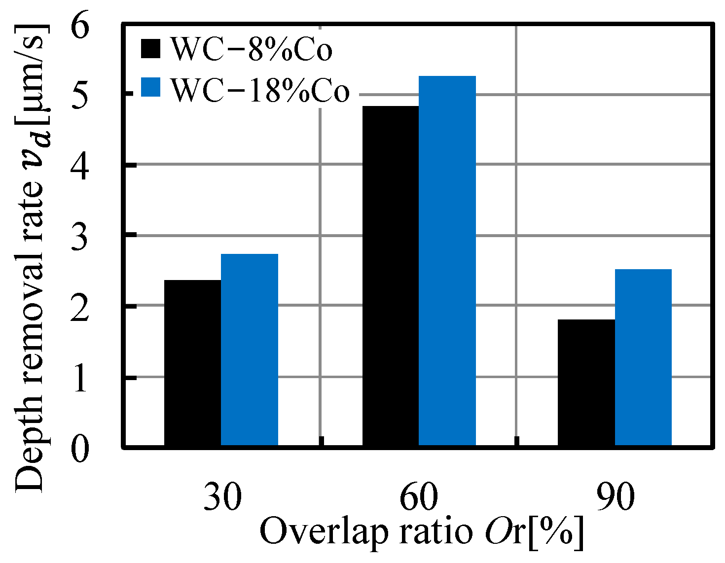
Figure 6 compares the vd of cemented carbides containing 8% and 18% Co at different overlap ratios. At all investigated overlap ratios, the WC–18%Co material exhibited a higher vd than the WC–8%Co material, with the difference being particularly pronounced at an overlap ratio of 90%. At N = 20, vd of WC–18%Co was approximately 1.1–1.4 times that of WC–8%Co. This trend is qualitatively consistent with the Co-rich redeposited material observed by EDS. The higher Co content may increase the contribution of the Co-containing binder phase to laser-induced melting and redeposition, potentially contributing to the higher vd observed in the present experiments. However, the two cemented carbides differ not only in Co content but also in other mechanical and thermal properties. Therefore, the present comparison demonstrates a dependence of laser-milling behavior on cemented-carbide grade, but the specific contribution of Co content cannot be isolated from the effects of the associated mechanical and thermal properties. Because each material and irradiation condition was tested once, statistical error bars or standard deviations could not be calculated for Figure 6.
Figure 6.
Effect of Co content on the depth removal rate at different overlap ratios. The laser milling test was performed once for each condition (n = 1). (Pave = 60 W, N = 20 raster-scanning cycles, f = 20 kHz, D = 77 μm, Td = 60 ns).
3.3.2. Effect of WC Grain Size
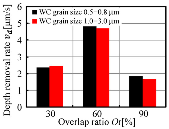
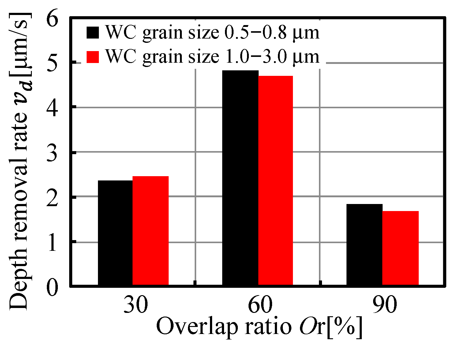
The effect of WC grain size was subsequently examined using cemented carbides with the same Co content of 8% but different WC grain sizes. Figure 7 shows the vd values of the two cemented carbides at overlap ratios of 30%, 60%, and 90%. At an overlap ratio of 30%, the difference in vd between the two materials was small. At 60%, the fine-grained material exhibited a slightly higher vd. At 90%, the difference became more pronounced, with the fine-grained material exhibiting a higher vd than the coarse-grained material. The vd value of the coarse-grained material was approximately 0.9 times that of the fine-grained material at an overlap ratio of 90%. Thus, the difference between the two materials became more pronounced at the high overlap ratio. This behavior may be related to differences in the responses of the two cemented-carbide grades to repeated laser irradiation. As shown in Table 1, although their Co contents are identical, the two grades differ in WC grain size, hardness, density, and thermal conductivity. Therefore, the present results indicate that the difference between the two cemented-carbide grades may affect laser-milling behavior, particularly under high-overlap conditions. However, the specific contribution of WC grain size cannot be isolated from the effects of the other differing material properties. Overall, the laser-milling characteristics depended on the cemented-carbide material grade. The difference between the grades with different WC grain sizes became more pronounced at high overlap ratios. These results indicate that laser-milling conditions should be selected based not only on the laser parameters but also on the material grade of the cemented carbide. Because each material and irradiation condition was tested once, statistical error bars or standard deviations could not be calculated for Figure 7.
Figure 7.
Effect of WC grain size on the depth removal rate at different overlap ratios. The laser milling test was performed once for each condition (n = 1). (Pave = 60 W, N = 20 raster-scanning cycles, f = 20 kHz, D = 77 μm, Td = 60 ns).
3.4. Cavity Geometry and Limitations of Laser Roughing
3.4.1. Formation of Tapered Cavity Geometry
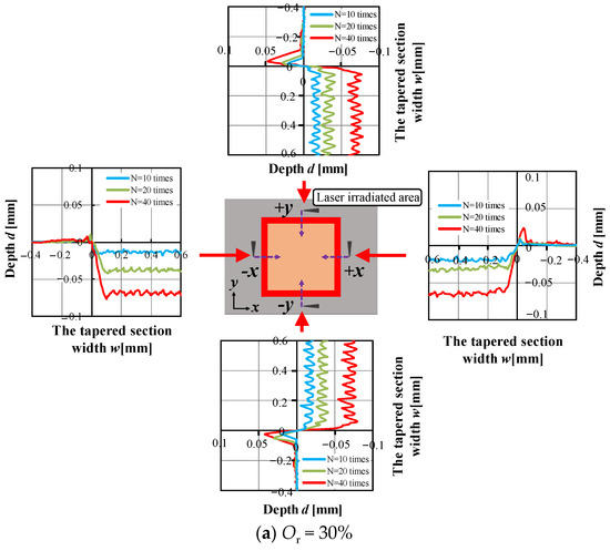
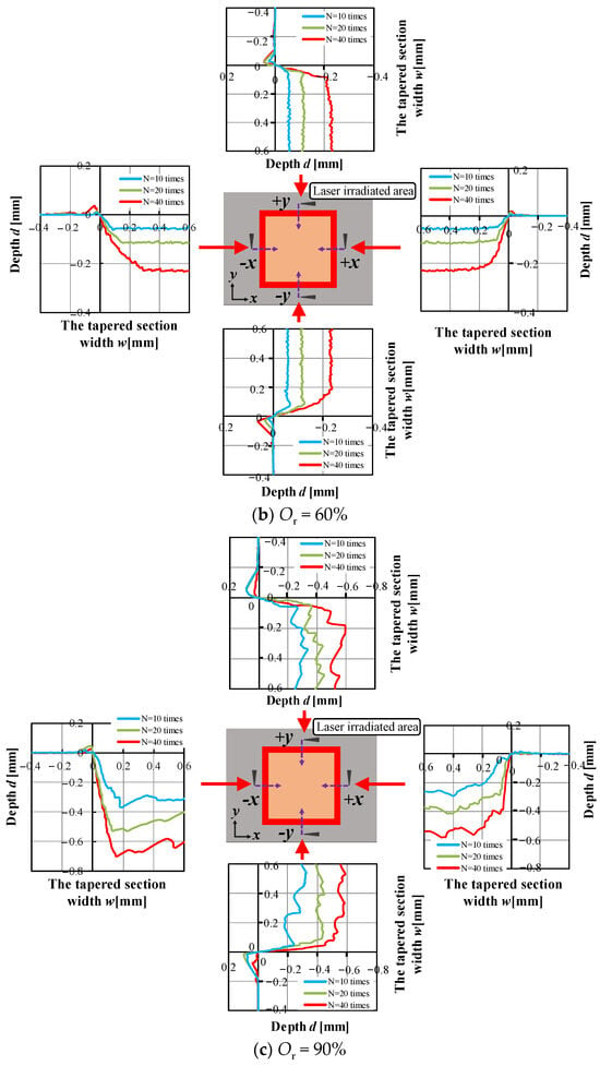
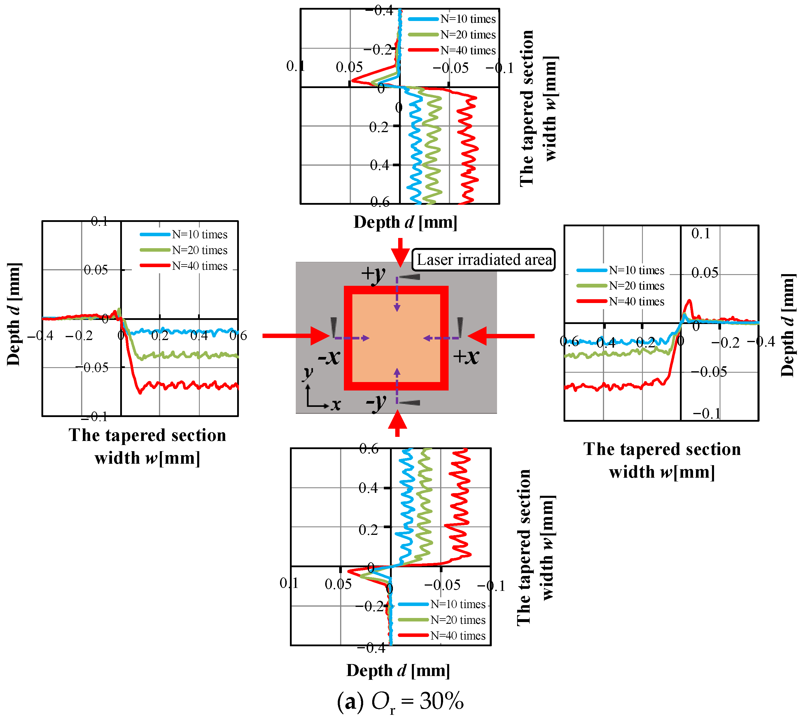
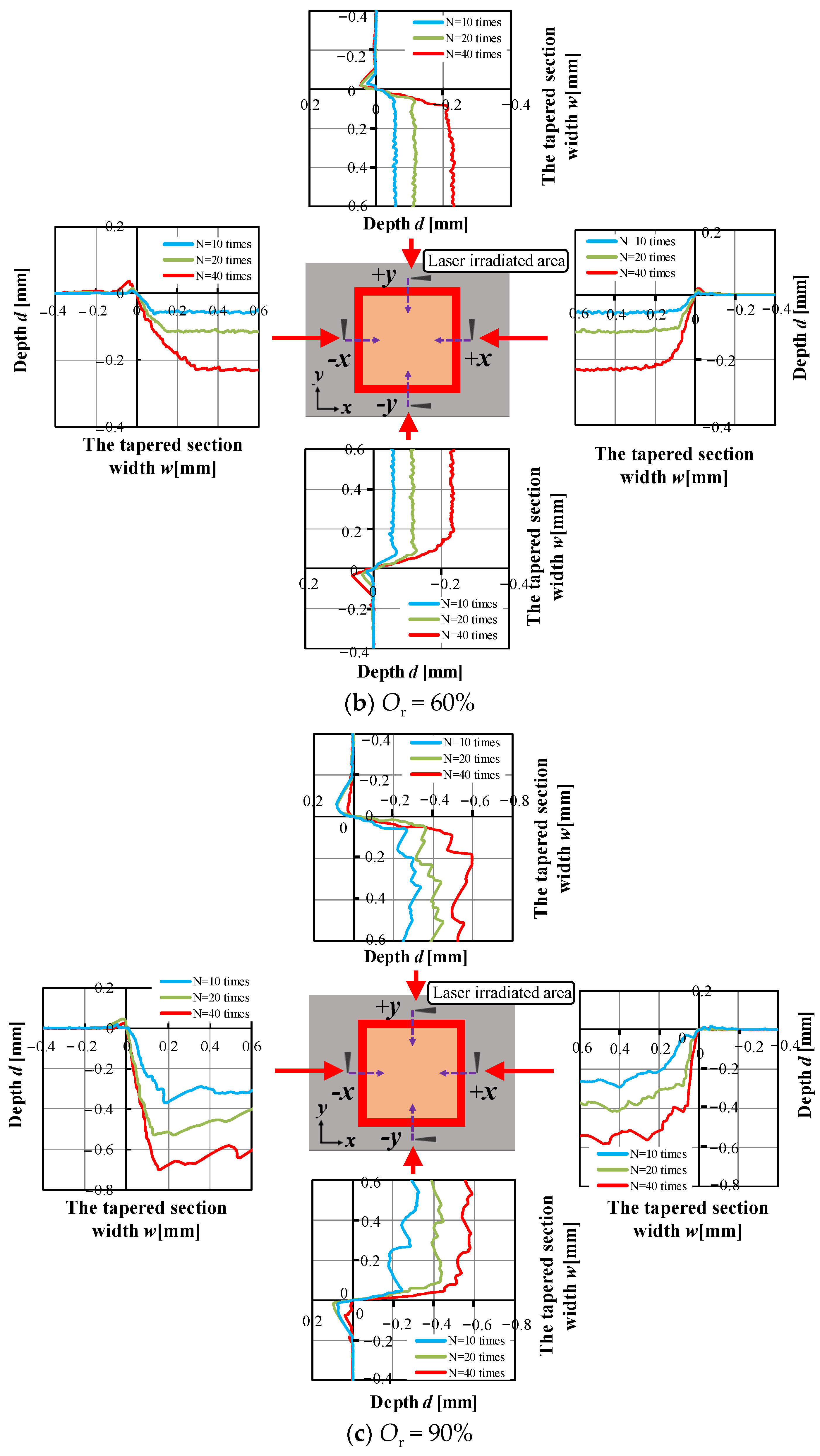
Although the laser-milling conditions and material dependence were investigated in the preceding sections, machining efficiency alone is insufficient to evaluate the applicability of laser milling to precision die manufacturing. In particular, dimensional accuracy and cavity geometry must also be considered. Figure 8 shows representative cross-sectional profiles of the laser-milled cavity. A tapered geometry was observed in the irradiated region, and the taper became more pronounced with increasing machining depth. At an overlap ratio of 90%, increasing the number of raster-scanning cycles from N = 10 to 40 increased the cavity depth from approximately 0.35 to 0.70 mm, while the maximum width of the tapered section increased from approximately 0.25 to 0.55 mm. These results indicate that dimensional deviations associated with cavity taper become more significant as the laser milling progresses to greater depths.
Figure 8.
Cross-sectional profiles of laser-milled cavities at different overlap ratios and numbers of raster-scanning cycles for VF-10 cemented carbide (Pave = 60 W, N = 10, 20, and 40 raster-scanning cycles, f = 20 kHz, D = 77 μm, Td = 60 ns). Solid arrows indicate the correspondence between the measurement locations and the corresponding profiles, while dashed arrows indicate the orientations of the coordinate axes used for the profiles.
3.4.2. Possible Mechanism of Taper Formation
The formation of the taper is considered to be associated with the change in the laser irradiance distribution as the machining depth increases. As the machined surface moves away from the initial focal position, the beam diameter increases and the laser power density decreases. However, the calculated Rayleigh length was substantially larger than the nominal machining depth. Therefore, the observed taper is unlikely to be explained solely by geometric beam divergence under the present optical conditions. The spatial variation in laser irradiance may contribute to narrowing of the effective material-removal region toward the bottom of the cavity. In addition, the evolving side-wall geometry during cavity formation may alter the local irradiation conditions. SEM observations of the cavity edge also revealed the deposition of resolidified material, which may contribute to the dimensional deviation at the cavity boundary [24]. Therefore, although increasing the irradiation depth enables efficient bulk material removal, the resulting taper prevents the laser milling process from being used as a final shaping process for high-precision cavities.
3.5. CAM-Based Evaluation of the Hybrid Machining Concept
The experimental results indicate that laser milling is suitable for bulk material removal, whereas mechanical machining is required for dimensional correction and surface finishing. To evaluate the potential benefit of assigning these functions to the two processes, three machining strategies were compared using CAM. Machining times were estimated using CAM-TOOL V14 (C&G Systems, Inc. Tokyo, Japan), a CAM software package used for ultra-precision micro-die/mold machining.
3.5.1. Definition of Machining Cases
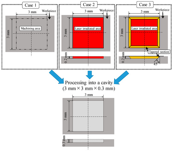
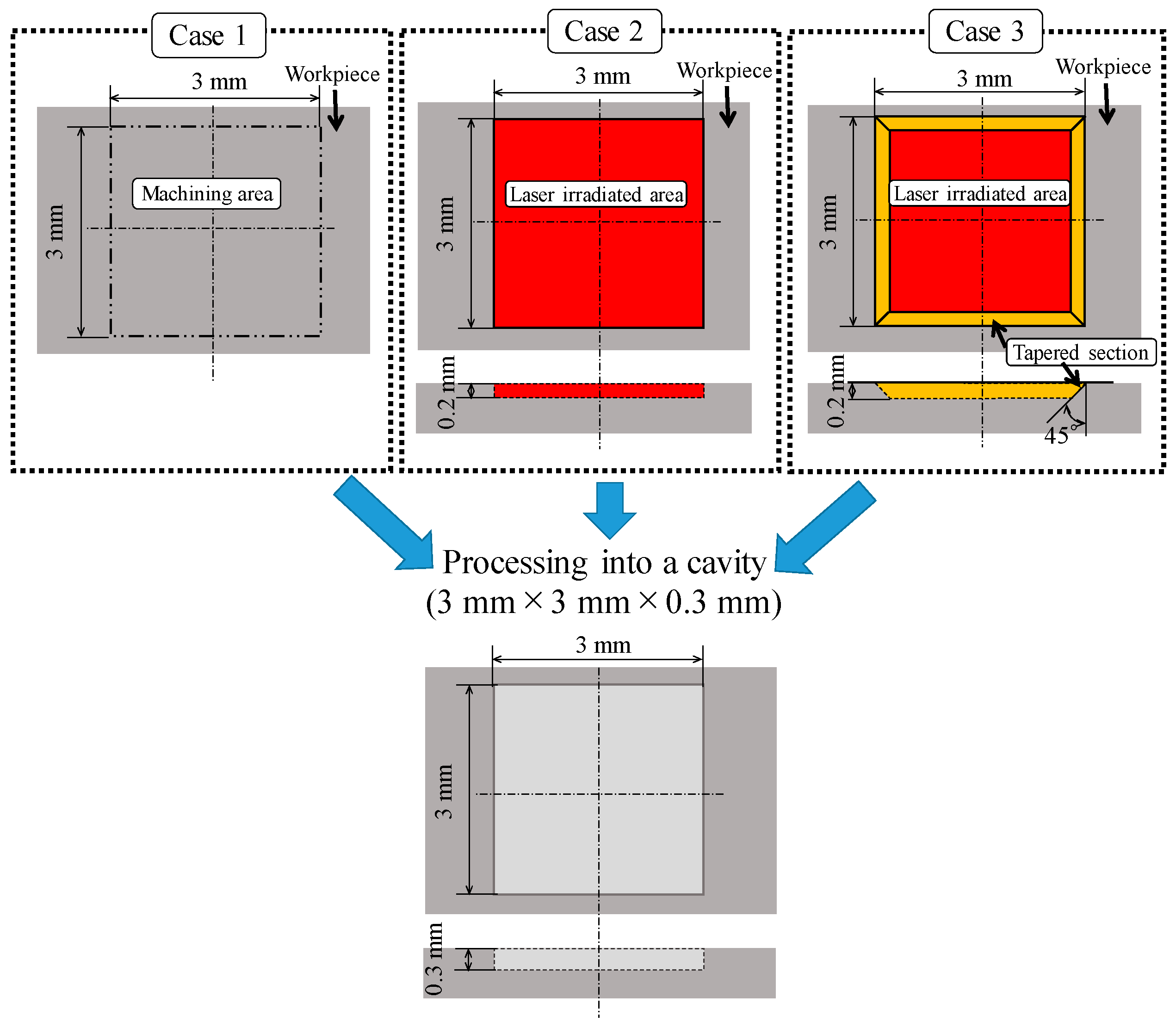
Three machining strategies, shown in Figure 9, were defined for a representative 3 mm × 3 mm × 0.3 mm cavity. Case 1 represents conventional mechanical machining. Case 2 represents the proposed hybrid strategy, in which the laser-generated cavity is assumed to be geometrically corrected by removing a uniform machining allowance. Case 3 represents a more conservative hybrid strategy that explicitly accounts for the tapered geometry observed experimentally.
Figure 9.
Schematic illustration of the three machining strategies evaluated using CAM. The gray, red, and yellow regions indicate the machining area, laser-irradiated area, and tapered section, respectively.
Case 1 corresponds to conventional machining using mechanical cutting alone. The 3 mm × 3 mm × 0.3 mm cavity is entirely rough-machined by mechanical cutting, followed by finish machining of the bottom and side surfaces. Case 2 introduces laser milling to remove most of the cavity depth before mechanical machining. Laser milling is used to remove approximately 0.2 mm of the cavity depth, followed by mechanical rough machining of the remaining 0.1 mm. The remaining 3 mm × 3 mm × 0.1 mm region is assumed to have no taper and is removed by mechanical cutting. The bottom and side surfaces are then finish-machined by cutting. In Case 1, the 45° tapered-area rough-machining step and laser-milling step were not performed. In Case 2, laser milling was performed, whereas no separate rough-cutting operation was assigned to the laser-generated tapered area because a uniform machining allowance was assumed. Case 3 additionally considers the tapered geometry generated by laser milling, with the remaining tapered region allocated to mechanical rough machining. For the CAM analysis, a representative taper angle of 45° was assumed based on the side-wall deviation observed experimentally in the laser-milled cavities. This angle was used as a representative condition to evaluate the effect of the laser-generated taper on the subsequent mechanical machining process. The 45° angle should not be regarded as a universal value for nanosecond laser milling, because the taper depends on the laser-processing conditions, material grade, machining depth, and beam geometry. Rather, it was selected as a representative value for the present CAM-based comparison. In this case, a 3 × 3 mm2 area was first rough-machined by laser milling to a nominal depth of 0.2 mm. Assuming that a tapered shape error was generated on the side surfaces, the remaining 3 mm × 3 mm × 0.1 mm region was then rough-machined by mechanical cutting. Finally, the bottom and side surfaces were finish-machined by cutting. Table 3 summarizes the processing conditions for each machining method. In Cases 2 and 3, laser milling was performed at an average power of 60 W and an overlap ratio of 60%. Under these conditions, the laser-milling time was 43 s (0.72 min), corresponding to 40 raster-scanning cycles and a machining depth of approximately 0.2 mm. For mechanical cutting, a PCD straight tool with a diameter of 0.5 mm was assumed, and the machining conditions were set based on interviews with a precision micro-die/mold manufacturer.
Table 3.
Cutting conditions for cavity fabrication.
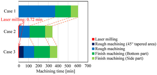
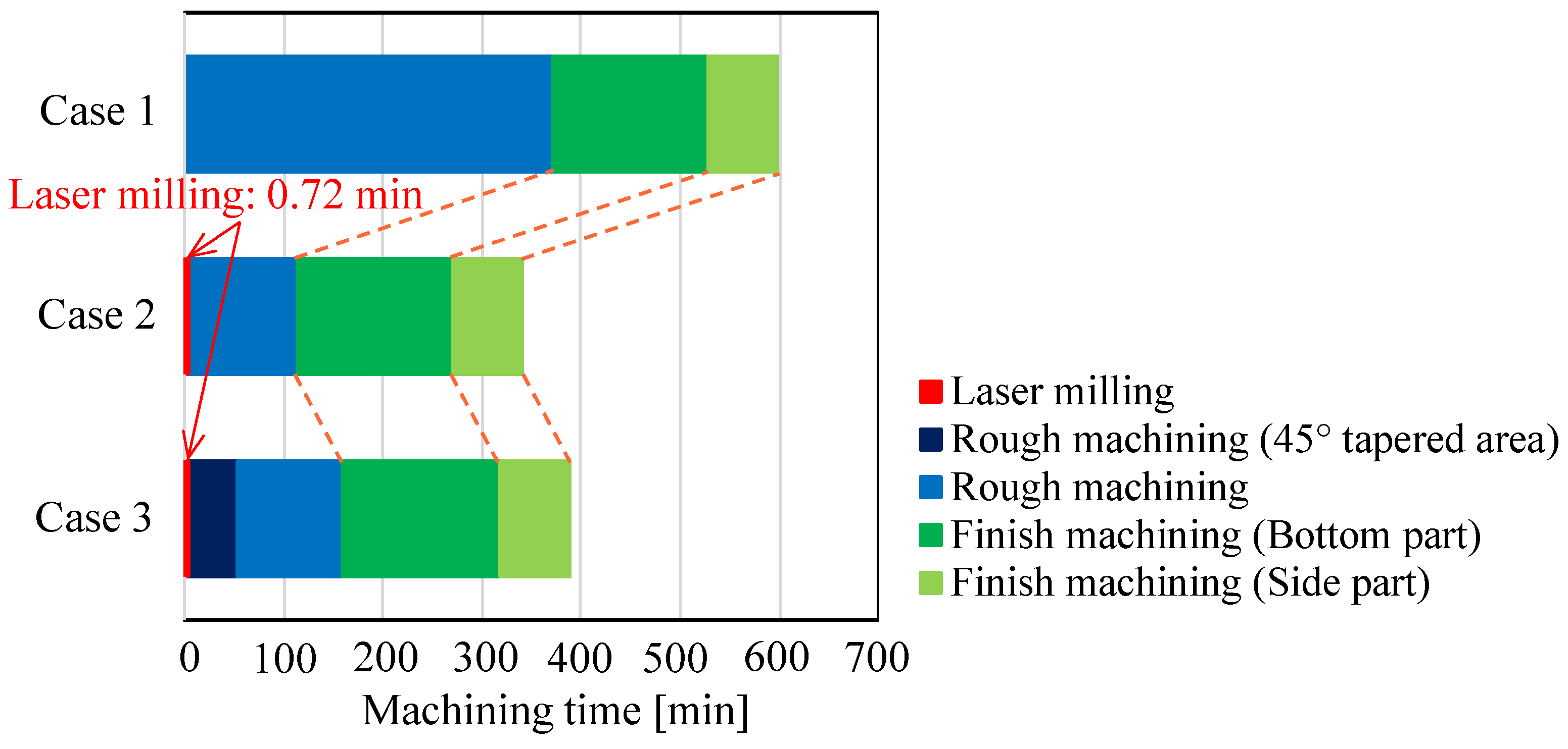
3.5.2. Estimated Machining Time
Figure 10 compares the estimated machining times for a single cavity. Introducing laser milling substantially reduces the amount of material that must be removed by mechanical rough machining. Consequently, both hybrid strategies require less estimated machining time than Case 1. The estimated machining times were approximately 599 min for Case 1, 337 min for Case 2, and 384 min for Case 3. Thus, Case 2 yielded the shortest estimated machining time, whereas Case 3 required additional mechanical machining because the tapered side-wall region generated by laser milling had to be removed to recover the intended cavity geometry. Nevertheless, Case 3 retained a substantial time advantage over conventional machining while explicitly accounting for the dimensional limitation of laser milling. Importantly, even when a representative taper based on the experimental observations was incorporated into the CAM model, Case 3 reduced the estimated machining time from 599 to 384 min, corresponding to an approximately 36% reduction.
Figure 10.
Estimated machining time for a single cavity for the three machining strategies.
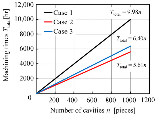
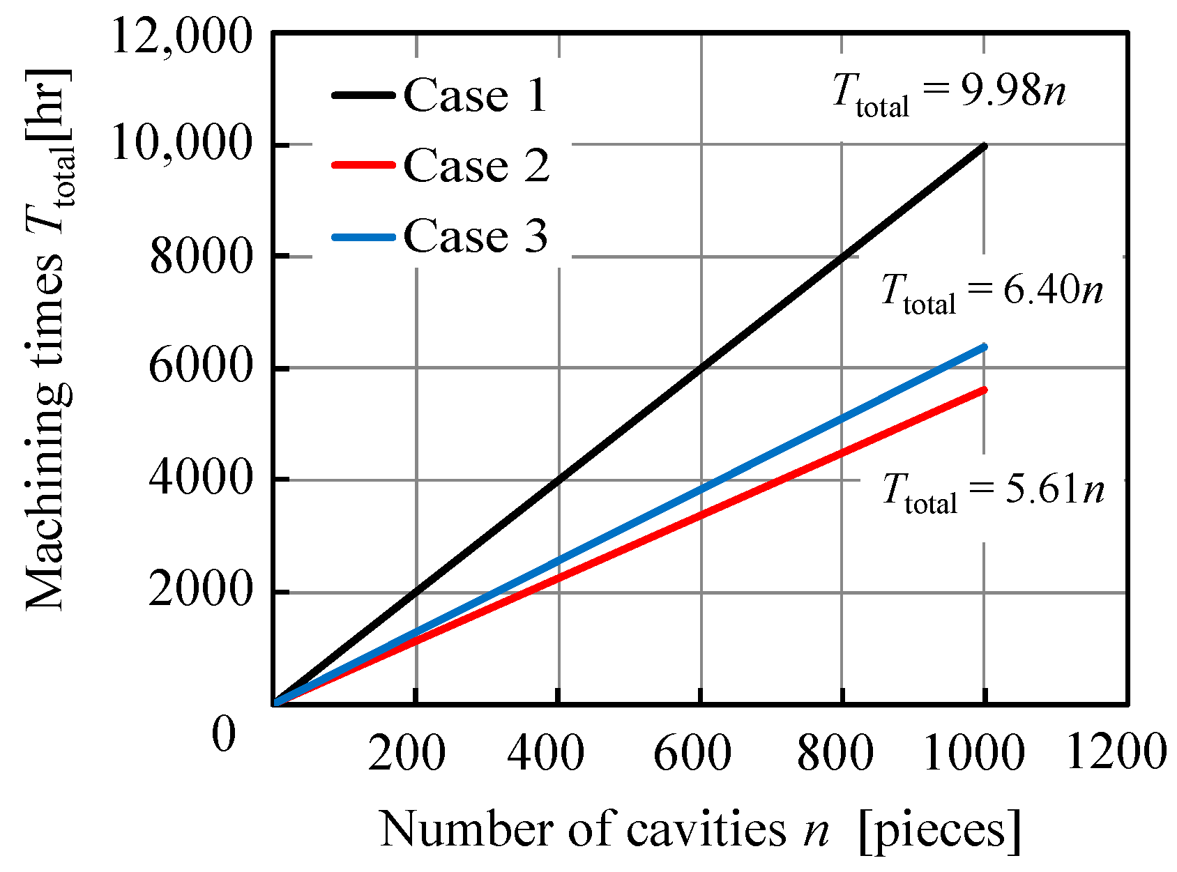
Because the machining time per cavity accumulates over multiple cavities, the difference between the three strategies becomes increasingly significant as the number of cavities increases. Figure 11 shows the estimated total machining time as a function of the number of cavities. The estimated total machining times were Ttotal = 9.98n, 5.61n, and 6.40n h for Cases 1, 2, and 3, respectively, where n is the number of cavities. For 1000 cavities, the CAM-based estimates indicate machining-time reductions of approximately 44% and 36% for Cases 2 and 3, respectively, compared with Case 1. These values represent CAM-based estimates rather than experimentally measured cycle times for continuous hybrid machining. In addition, the estimates do not include setup, tool-change, workpiece-transfer, or inter-cavity positioning times. Therefore, the calculated reductions should be regarded as estimates of the machining-time advantage under the assumed processing conditions rather than direct predictions of total production time. Although introducing laser milling requires an initial investment in laser-processing equipment, conventional mechanical machining of cemented carbide requires diamond-coated or PCD tools, for which tool wear and replacement can contribute substantially to operating costs. By removing a large portion of the workpiece material by laser milling before mechanical machining, the proposed process has the potential to reduce the cutting distance and associated tool consumption. The present results demonstrate the potential of the proposed process to reduce machining time and may also reduce machining-related costs; however, further experimental validation is required to quantify the actual reductions in machining time and tool consumption and to assess the resulting cost benefits. Energy consumption was not evaluated in the present study because the electrical power consumption of the laser-processing system and the mechanical machine tool was not measured. Therefore, the present CAM-based comparison is limited to machining time and does not establish an energy advantage of the proposed hybrid strategy. Future work should include direct measurement of the electrical energy consumed by both processes.
Figure 11.
Estimated total machining time as a function of the number of cavities for the three machining strategies.
3.6. Applicability and Limitations
The practical applicability of the proposed process is subject to several limitations. Nanosecond-pulsed laser milling is suitable for bulk material removal from cemented-carbide dies, but its use as a final shaping process is limited by resolidified deposits, cracks, and depth-dependent taper. In addition, industrial implementation requires consideration of laser-system investment, process integration with machine tools, extraction of laser-generated debris and fumes, dimensional control of the laser-generated cavity, and reliable control of the machining allowance for subsequent mechanical finishing. The present study also did not experimentally validate the complete sequential process or measure its energy consumption. Therefore, the CAM-based results should be regarded as an initial assessment of the potential of the proposed hybrid process rather than as a direct demonstration of industrial production performance.
4. Conclusions
In this study, the applicability of nanosecond-pulsed laser milling as a rough-machining process for cemented-carbide dies was investigated, with subsequent mechanical machining used for dimensional correction and surface finishing. The effects of laser-processing conditions, material composition and microstructure, and cavity geometry were evaluated, and the machining-time reduction potential of the proposed sequential hybrid machining concept was estimated using CAM. The main conclusions are as follows:
- (1)
- Nanosecond-pulsed laser milling enabled substantial material removal from WC–Co cemented carbide. The depth removal rate increased with average laser power, while an overlap ratio of 60% provided the highest depth removal rate among the investigated conditions with relatively low surface roughness.
- (2)
- Surface morphology strongly depended on the overlap ratio. Low overlap produced periodic irradiation marks, whereas excessive overlap promoted relatively large surface irregularities and the formation of resolidified deposits.
- (3)
- EDS analysis of the resolidified deposits detected oxygen, indicating that oxidation occurred during laser irradiation. The deposits also exhibited a relatively higher Co content than the base material, suggesting that Co-containing material may be involved in the melting and redeposition process during nanosecond laser irradiation.
- (4)
- The laser-milling characteristics varied with cemented-carbide material grade. Under the investigated conditions, the material containing 18% Co exhibited a higher depth removal rate than the material containing 8% Co, while the difference between the grades with different WC grain sizes became more pronounced at high overlap ratios.
- (5)
- Increasing machining depth was accompanied by the formation of a tapered cavity geometry, which was considered to be primarily associated with increasing defocus and the resulting reduction in effective laser irradiance. These results indicate that subsequent mechanical machining is required for dimensional correction and surface finishing when relatively deep cavities are produced by laser roughing. Thus, the practical role of nanosecond laser milling in the proposed process is bulk material removal rather than final cavity shaping.
- (6)
- CAM-based estimation indicated that the proposed sequence of laser roughing followed by mechanical machining has the potential to substantially reduce machining time for cemented-carbide dies. For 1000 cavities, the estimated machining-time reductions were approximately 44% and 36% for Cases 2 and 3, respectively, compared with conventional machining. These results indicate that the proposed process can reduce the amount of mechanical cutting required for cemented-carbide die cavities and may consequently reduce machining time and tool consumption. However, the complete sequential hybrid process, energy consumption, tool wear, and long-term process stability were not experimentally evaluated in the present study. Experimental validation of these aspects is therefore required before practical industrial implementation.
Author Contributions
Conceptualization, K.O. and H.N.; methodology, K.O.; validation, K.O.; investigation, K.O. and T.I.; resources, H.T. and H.N.; data curation, K.O., T.I. and H.T.; writing—original draft preparation, K.O.; writing—review and editing, K.O., T.I., H.T. and H.N.; supervision, H.N.; project administration, K.O.; funding acquisition, H.N. All authors have read and agreed to the published version of the manuscript.
Funding
This research received no external funding.
Data Availability Statement
The original contributions presented in this study are included in the article. Further inquiries can be directed to the corresponding author.
Conflicts of Interest
The authors declare no conflict of interest.
References
- Yilbas, B.S.; Arif, A.F.M.; Karatas, C.; Ahsan, M. Cemented carbide cutting tool: Laser processing and thermal stress analysis. Appl. Surf. Sci. 2007, 253, 5544–5552. [Google Scholar] [CrossRef] [Scilit]
- Hintze, W.; Steinbach, S.; Susemihl, C.; Kähler, F. HPC-milling of WC-Co cemented carbides with PCD. Int. J. Refract. Met. Hard Mater. 2018, 72, 126–134. [Google Scholar] [CrossRef] [Scilit]
- Suzuki, H.; Moriwaki, T.; Yamamoto, Y.; Goto, Y. Precision cutting of aspherical ceramic molds with micro PCD milling tool. CIRP Ann. 2007, 56, 131–134. [Google Scholar] [CrossRef] [Scilit]
- Nakamoto, K.; Katahira, K.; Ohmori, H.; Yamazaki, K.; Aoyama, T. A study on the quality of micro-machined surfaces on tungsten carbide generated by PCD micro end-milling. CIRP Ann. 2012, 61, 567–570. [Google Scholar] [CrossRef] [Scilit]
- Wu, X.; Li, L.; He, N.; Zhao, G.; Shen, J. Experimental investigation on direct micro milling of cemented carbide. Micromachines 2019, 10, 147. [Google Scholar] [CrossRef] [Scilit] [PubMed]
- Wu, X.; Li, L.; He, N.; Zhao, G.; Jiang, F.; Shen, J. Study on the tool wear and its effect of PCD tool in micro milling of tungsten carbide. Int. J. Refract. Met. Hard Mater. 2018, 77, 61–67. [Google Scholar] [CrossRef] [Scilit]
- Okada, M.; Yoshida, A.; Furumoto, T.; Watanabe, H.; Asakawa, N.; Otsu, M. Mechanisms and characteristics of direct cutting of tungsten carbide using a diamond-coated carbide end mill. Int. J. Adv. Manuf. Technol. 2016, 86, 1827–1839. [Google Scholar] [CrossRef] [Scilit]
- Dumitru, G.; Lüscher, B.; Krack, M.; Bruneau, S.; Hermann, J.; Gerbig, Y. Laser processing of hardmetals: Physical basics and applications. Int. J. Refract. Met. Hard Mater. 2005, 23, 278–286. [Google Scholar] [CrossRef] [Scilit]
- Li, T.; Lou, Q.; Dong, J.; Wei, Y.; Liu, J. Selective removal of cobalt binder in surface ablation of tungsten carbide hardmetal with pulsed UV laser. Surf. Coat. Technol. 2001, 145, 16–23. [Google Scholar] [CrossRef] [Scilit]
- Li, T.; Lou, Q.; Dong, J.; Wei, Y.; Liu, J. Escape of carbon element in surface ablation of cobalt cemented tungsten carbide with pulsed UV laser. Appl. Surf. Sci. 2001, 172, 51–60. [Google Scholar] [CrossRef] [Scilit]
- Dumitru, G.; Romano, V.; Weber, H.P.; Sentis, M.; Marine, W. Ablation of carbide materials with femtosecond pulses. Appl. Surf. Sci. 2003, 205, 80–85. [Google Scholar] [CrossRef] [Scilit]
- Karatas, C.; Yilbas, B.S.; Aleem, A.; Ahsan, M. Laser treatment of cemented carbide cutting tool. J. Mater. Process. Technol. 2007, 183, 234–240. [Google Scholar] [CrossRef] [Scilit]
- See, T.L.; Chantzis, D.; Royer, R.; Metsios, I.; Antar, M.; Marimuthu, S. A comparison of the DPSS UV laser ablation characteristic of 1024 and H10F WC-Co. Opt. Laser Technol. 2017, 92, 101–108. [Google Scholar] [CrossRef] [Scilit]
- Chu, C.; Zhang, Q.; Zhuo, H.; Zhang, Z.; Zhu, Y.; Fu, Y. Investigation on the ablation behavior of cemented tungsten carbide by a nanosecond UV laser. J. Manuf. Process. 2021, 71, 461–471. [Google Scholar] [CrossRef] [Scilit]
- Zhang, Q.; Chu, C.; Zhang, Z.; Zhu, Y.; Fu, Y. Nanosecond UV laser induced subsurface damage mechanics of cemented tungsten carbide. Ceram. Int. 2021, 47, 32927–32937. [Google Scholar] [CrossRef] [Scilit]
- Fang, S.; Llanes, L.; Guo, Y.B.; Bähre, D. Synergic effects of nanosecond laser ablation and PVD-coating on cemented carbides: Assessment on Surface and Mechanical Integrity. Metals 2024, 14, 34. [Google Scholar] [CrossRef] [Scilit]
- Fang, S.; Llanes, L.; Bähre, D. Laser surface texturing of a WC-CoNi cemented carbide grade: Surface topography design for honing application. Tribol. Int. 2018, 122, 236–245. [Google Scholar] [CrossRef] [Scilit]
- Wang, H.P.; Guan, Y.C.; Zheng, H.Y. Smooth polishing of femtosecond laser induced craters on cemented carbide by ultrasonic vibration method. Appl. Surf. Sci. 2017, 426, 399–405. [Google Scholar] [CrossRef] [Scilit]
- Bouzakis, K.-D.; Charalampous, P.; Kotsanis, T.; Skordaris, G.; Bouzakis, E.; Denkena, B.; Breidenstein, B.; Aurich, J.C.; Zimmermann, M.; Herrmann, T.; et al. Effect of HM substrates’ cutting edge roundness manufactured by laser machining and micro-blasting on the coated tools’ cutting performance. CIRP J. Manuf. Sci. Technol. 2017, 18, 188–197. [Google Scholar] [CrossRef] [Scilit]
- Sahu, A.K.; Malhotra, J.; Jha, S. Laser-based hybrid micromachining processes: A review. Opt. Laser Technol. 2022, 146, 107554. [Google Scholar] [CrossRef] [Scilit]
- Zhao, G.; Zhao, B.; Ding, W.; Xin, L.; Nian, Z.; Peng, J.; He, N.; Xu, J. Nontraditional energy-assisted mechanical machining of difficult-to-cut materials and components in aerospace community: A comparative analysis. Int. J. Extrem. Manuf. 2024, 6, 022007. [Google Scholar] [CrossRef] [Scilit]
- Zeng, H.; Liu, Y. Optimization of laser-tool distance and laser power in laser-assisted milling under material softening and surface quality constraints. Int. J. Adv. Manuf. Technol. 2024, 134, 4667–4675. [Google Scholar] [CrossRef] [Scilit]
- Zhang, C.; Qiu, Y.; Jiao, F.; Wang, J.; Wang, X. Research on temperature characteristics and the machining process in laser ultrasonic-assisted milling of cemented carbide. Int. J. Refract. Met. Hard Mater. 2025, 128, 107031. [Google Scholar] [CrossRef] [Scilit]
- Fang, S.; Lima, R.; Sandoval, D.; Bähre, D.; Llanes, L. Ablation Investigation of Cemented Carbides Using Short-Pulse Laser Beams. Procedia CIRP 2018, 68, 172–177. [Google Scholar] [CrossRef] [Scilit]

Disclaimer/Publisher’s Note: The statements, opinions and data contained in all publications are solely those of the individual author(s) and contributor(s) and not of MDPI and/or the editor(s). MDPI and/or the editor(s) disclaim responsibility for any injury to people or property resulting from any ideas, methods, instructions or products referred to in the content. |
© 2026 by the authors. Licensee MDPI, Basel, Switzerland. This article is an open access article distributed under the terms and conditions of the Creative Commons Attribution (CC BY) license.