


Abstract
This paper presents the results of experimental and numerical analysis of fracture mechanics testing of ductile metallic materials using a non-standard procedure with PRNT (pipe ring notched tensile) ring-shaped specimens, introduced in previous publications through analysis of 3D-printed polymer rings. The main focus of this research is the determination of the values of the plastic geometry factor ηpl since the specimen is not a standard one. Toward this aim, the finite element software package Simulia Abaqus was applied to evaluate the J-integral (by using the domain integral method) and the F-CMOD curve so that the plastic geometry factor ηpl can be evaluated for different values of the ratio of crack length to specimen width (a0/W = 0.45 ÷ 0.55). In this way, a procedure and the possibility of practical implementation on the thin-walled pipelines are established.
1. Introduction
Determining the fracture mechanics parameters is a key segment in the assessment and enhancement of the safety and longevity of materials and structures, especially when they are exposed to extreme load conditions in the presence of damage. In this research, one group of such structures considered is thin-walled pipelines, which are used in practically all the process industry branches. Since the standard procedures prescribed by ASTM and ISO standards are not the most relevant if one of the criteria is not met, which is the testing of materials in a plane strain state, it is necessary to develop a complete procedure for the determination of fracture mechanics parameters for thin-walled pipelines.
The integrity and reliability of pipelines are critical for the safe transport of fluids and gases in various industries. Standard fracture mechanics testing methods often fail to address the specific challenges posed by thin-walled pipelines. To overcome these limitations, recent research has explored non-standard procedures and specimen geometries for determining the fracture mechanics parameters. This introduction contains reviews of the key studies that have contributed to the development of such methods, while Figure 1 contains some of the specimen geometries.
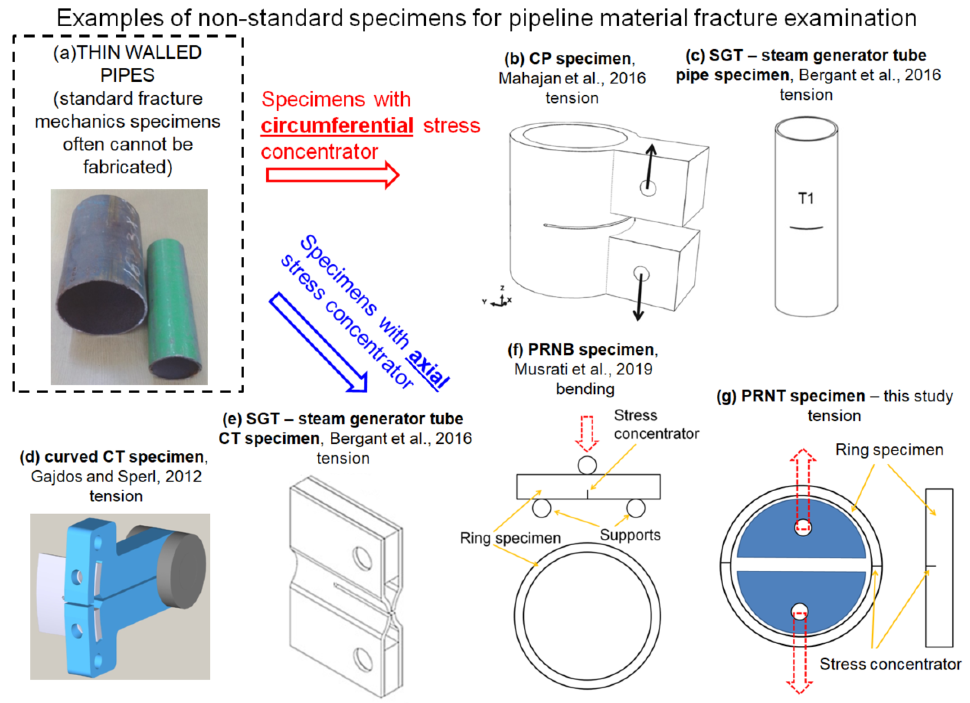
Figure 1.
A scheme with examples of non-standard specimens with stress concentrators in different directions for fracture assessment of pipeline materials. (b): Reprinted with permission from [1], 2016, John Wiley and Sons. (c,e): Reprinted with permission from [2], 2016, Elsevier. (d): Reprinted from [3], Creative Commons Attribution 3.0 License.One significant approach in the pipeline design is the leak-before-break (LBB) concept, which is based on the fracture resistance curve obtained from various specimens. Koo et al. introduced the compact pipe (CP) geometry for fracture toughness testing, demonstrating that Q-stress values from these specimens were more representative of real-world conditions. By controlling the length of welded levers, different stress conditions could be simulated [4].
One significant approach in the pipeline design is the leak-before-break (LBB) concept, which is based on the fracture resistance curve obtained from various specimens. Koo et al. introduced the compact pipe (CP) geometry for fracture toughness testing, demonstrating that Q-stress values from these specimens were more representative of real-world conditions. By controlling the length of welded levers, different stress conditions could be simulated [4].
Mahajan et al. conducted numerical calculations on CP specimens to study the impact of parameters such as wall thickness and crack type. Their results highlighted the utility of the CP specimens in providing insights into the fracture mechanics of pipeline materials under different stress conditions [1]. Another attempt to define a method for evaluating the fracture behavior of thin-walled pipes involved the creation of curved CT specimens, as proposed by Gajdos and Sperl [3]. They tested two types of specimens, curved CT specimens and flattened CT specimens (cut from pipes and then plastically deformed), achieving circumferential loading crucial for axial damage simulation. Bergant et al. developed geometries similar to standard fracture mechanics specimens made from two segments of thin-walled pipe, including SENB (single edge notched bending), CT (compact tension), and MT (middle crack tension) geometries. Their research included experimental determination of resistance curves and geometric factors like ηpl, showing these geometries are suitable for fracture mechanics testing and pipeline integrity assessment [2].
Rais et al. developed the pin loading tension (PLT) test for assessing the behavior of cracks in thin-walled pipe materials, particularly 9Cr ODS steel pipes [5]. They used the finite element calculations to determine geometric functions and elastic and plastic components of the J-integral, highlighting the methodology’s potential for irradiated materials testing. They also calculated the ηpl factor using different methods, including the separation parameter method, to ensure the accuracy of their result. Sanyal et al. focused on predicting J-R curves of thin-walled fuel pin specimens, which are essential for evaluating the integrity of nuclear fuel cladding. Their research provided critical insights into the fracture mechanics of these specialized materials under operational conditions. They also calculated the ηpl factor to better understand the plastic zone development at the crack tip [6]. Some specimen geometries have been developed specifically to address the influence of the environment. In the study [7], Boot et al. dealt with pipeline steels in a hydrogen gas (H2) environment, proposing a miniature hollow pipe-like tensile specimen.
Rodolfo and Vanderely compared four geometries with varying thicknesses to evaluate the suitability of ring-type specimens for determining stress intensity factors in plastic materials. Their research confirmed the suitability of ring-shaped specimens for fracture mechanics examination, despite some limitations due to elastic energy storage during testing [8].
Matvienko and Gubeljak developed a ring-shaped specimen with a sharp notch subjected to bending, known as PRNB (pipe ring notched bending). Their research, based on experimental and numerical analysis, showed comparable fracture toughness for PRNB, CT, and SENB specimens, suggesting the viability of ring-shaped specimens for pipeline material testing [9,10].
The studies of Musrati et al. involved experimental and micromechanical model analysis of crack growth in PRNB specimens, considering different notch dimensions and shapes. Their results indicated that specimen dimensions and initial crack sizes did not significantly impact crack growth curves, assuming a constant width-to-thickness ratio [11].
Further research by Damjanović et al. examined the influence of residual stresses, which are often a result of manufacturing processes, on the fracture behavior of PRNB specimens. Their study concluded that residual stresses had a negligible effect on the fracture behavior of PRNB specimens. Recent studies have also explored the impact of twisting on fracture behavior, with numerical models indicating significant torsional effects on PRNB specimen fracture behavior [12,13].
Figure 1 contains examples of non-standard specimens from the literature mentioned previously in this section. Stress concentrator (pre-crack or sharp notch) in some of these specimens is positioned in the circumferential direction, while the other geometries have axially positioned stress concentrators, like in this study.
The development of new methodologies for determining the fracture mechanics parameters includes the use of elastic–plastic fracture mechanics. This approach considers the plastic deformation that occurs at the crack tip, providing a more accurate representation of the fracture process in ductile materials, which are typically used for pipelines (a possible exception is exploitation at low temperatures). Elastic–plastic fracture mechanics involves parameters such as the J-integral, which quantifies the energy release rate, and the crack tip opening displacement (CTOD). These parameters are critical for understanding the fracture behavior of materials that exhibit significant plastic deformation before failure.
Research on the behavior of pipeline materials in the hoop direction highlights the importance of developing specific methodologies for evaluating mechanical properties based on previous experience [14]. Travica et al. developed a procedure for determining the stress–strain behavior of pipe ring tensile specimens (PRTSs) in the hoop direction using the digital image correlation (DIC) method. The aim of this study was to investigate the influence of specimen geometry, infill percentage, and printing method on 3D-printed polymer material behavior, utilizing a specially designed tool with D-blocks. The results demonstrated that the DIC method is effective in mapping complete strain fields in PRTS, enabling reliable characterization of pipeline mechanical properties. Experiments revealed that specimens with 90% and 100% infill exhibit similar mechanical properties, whereas specimens with 60% infill show more pronounced differences in behavior. Those differences are reflected in stress–strain curves and cross-sectional dimensions after fracture, indicating that specimens with higher infill percentages provide more consistent and reliable results. In addition to testing the polymer pipes, there are also proposals for specimen geometry for examination of polymer pipe butt joints; two of them are presented in [15].
To further advance methodologies for evaluating the fracture mechanics parameters, Trajković et al. [16] proposed a new specimen geometry called a pipe ring notched tension (PRNT) specimen, designed for assessing the fracture resistance of thin-walled pipelines. The PRNT specimens were fabricated using the selective laser sintering (SLS) method, and the testing involved applying internal pressure simulated by a specially designed tool with D-blocks. Experimental results showed that PRNT specimens allow precise measurement of parameters, such as crack mouth opening displacement (CMOD), crack tip opening displacement (CTOD), and the J-integral, while the DIC method enabled the evaluation of force-CMOD and force-CTOD curves [17].
Numerical analysis, utilizing the domain integral technique, enabled the determination of J-integral values along the crack front. A comparison between PRNT and SENT (single edge notch tension) specimens revealed an asymmetric distribution of the J-integral for PRNT specimens due to their cylindrical geometry, whereas SENT specimens showed a symmetric distribution. These findings emphasize the importance of considering specimen geometry when determining fracture mechanics parameters [16]. More details about the numerical analysis of fracture mechanics problems, based on the finite element method, are shown in [18,19].
Building on previous studies, new contributions arise from the research of Trajković et al., where the geometry of PRNT specimens with sharp notches or cracks was developed. The aim of this research was to define a methodology for testing the fracture resistance of pipeline materials using non-standard specimens fabricated by selective laser sintering (SLS) from PA12 polyamide. Experimental investigations included monitoring deformations using the DIC method and employing a specially designed tool for loading specimens in the hoop direction. The results indicated that PRNT specimens provide reliable data on the fracture resistance of materials and enable the determination of parameters such as the stress intensity factor (KI) and the J-integral [16].
By comparing the PRNT and SENT specimens, it was observed that specimen geometry and loading conditions caused differences in the force-CMOD curves, but similar trends were identified when considering the influence of crack length. A key advantage of PRNT specimens is their suitability for application on specimens cut directly from pipelines, ensuring a more direct correlation with operational conditions [16,17].
The PRNT specimen represents advancement over conventional fracture mechanics testing methods, as it enables the testing of thin-walled pipes without the need for standard specimens that require substantial material thickness, ensuring greater relevance of the results to real operating conditions. An additional advantage of PRNT specimens is their ability to be directly extracted from in-service pipelines used in the oil, gas, and chemical industries, eliminating the need for additional flattening of specimens, which often introduces residual stresses and can affect the accuracy of testing results. This methodology allows for more reliable assessments of pipeline integrity under actual operating conditions, contributing to the precise determination of fracture mechanics parameters and enhancing the safety of industrial pressure systems.
Moreover, this method is particularly suitable for evaluating the axial crack propagation in pipelines, which can result from external mechanical damage, such as third-party interference, corrosion-induced defects, or pressure fluctuations in operational environments. It can be used for the selection of material for a new pipeline, along with other mechanical tests, or for determining the degradation level of a pipe withdrawn from exploitation. In comparison with some other non-standard methodologies, the PRNT specimen does not require a complex fabrication and/or testing procedure.
The focus in this paper is on a recently proposed ring-shaped specimen (PRNT) with a sharp stress concentrator and testing its fracture mechanics properties using both experimental and numerical methods. The methodology aimed to address the advantages and limitations of existing procedures, particularly for the thin-walled pipelines. The new specimen and testing procedure are expected to provide more accurate and reliable data for assessing pipeline material fracture resistance, enhancing the safety and integrity of industrial pipeline systems.
2. Materials and Methods
The materials used in this study were P235TR1 and P235GH steels, which are commonly applied in the manufacturing of pipelines. These materials were selected not only for their widespread usage in pipeline systems but also because specimens can be directly obtained from pipelines in service. Their mechanical properties make them suitable for a wide range of industrial applications, including the transport of liquids and gases under varying pressure conditions. It should be noted that tests on all specimen geometries are performed on P235TR1 pipe specimens (seam pipes), while results for P235GH pipe specimens (seamless) are given only to illustrate the difference of tensile properties.
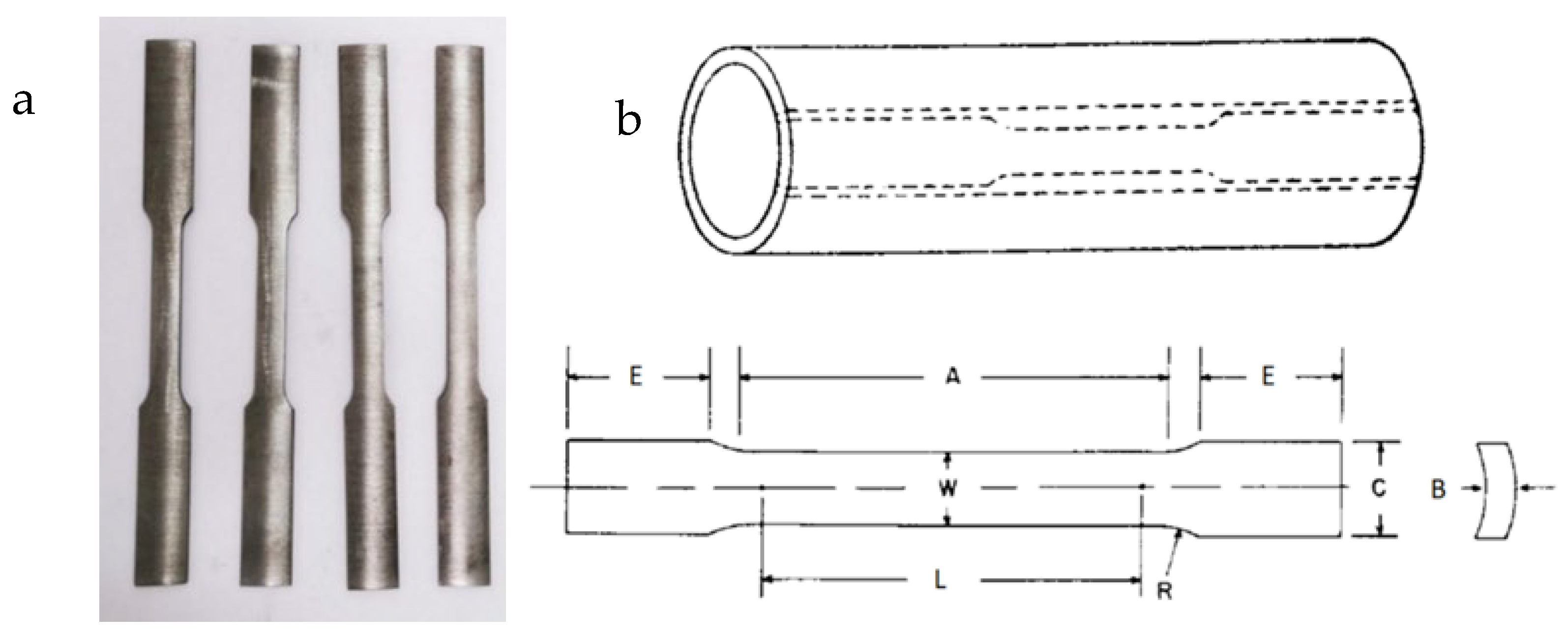
The first group of specimens consisted of standard tensile specimens prepared according to ASTM E8/E8M [20]. Two specimens were tested for each material (P235TR1 and P235GH). The dimensions of the specimens are presented in Table 1, with the corresponding geometry shown in Figure 2.
Table 1.
Dimensions of standard tensile specimens.
Figure 2.
Standard tension specimens: (a) P235TR1 (left two) and P235GH (right two); (b) Sketch of a standard tension specimen obtained from a pipe. E and C are the length and width of the grip section, A is the length of the reduced section, R is the fillet radius; other dimensions are mentioned in Table 1.
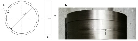
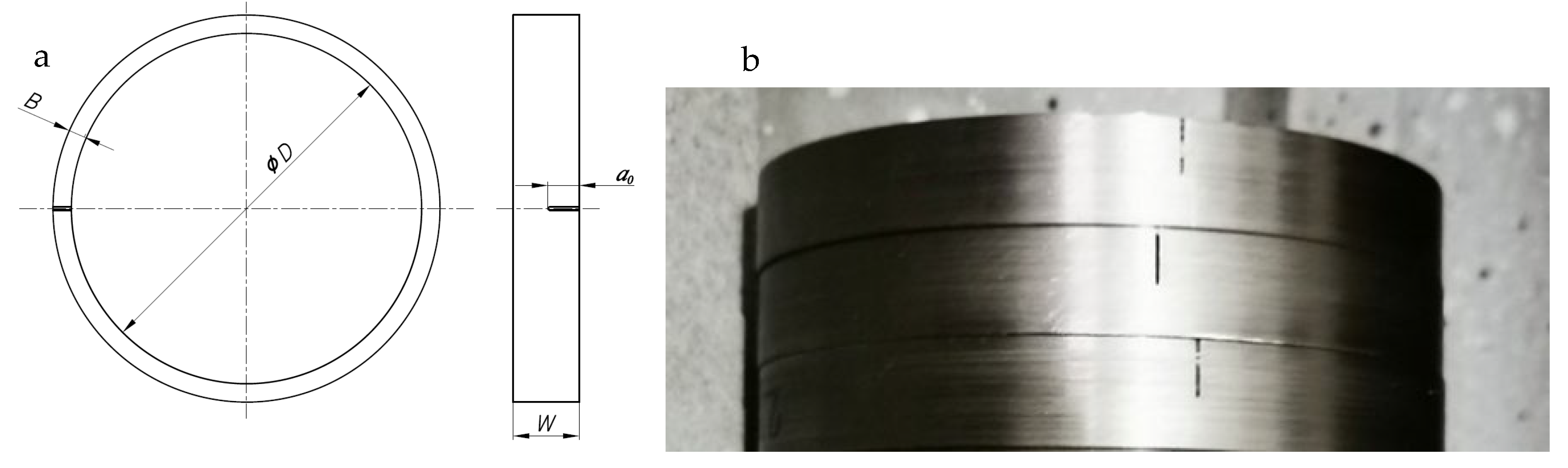
To examine the fracture resistance of the pipeline material, three pipe ring notched tensile specimens (PRNTs) are made from P235TR1 steel by using the CNC laser cutting machine with a notch width of 0.35 mm. Dimensions of PRNT specimens are shown in Table 2, with the geometry illustrated in Figure 3. This specimen geometry has been proposed and applied in our previous studies [16,17], where the specimens were additively manufactured from polymer materials.
Table 2.
Dimensions of PRNT specimens.
Figure 3.
PRNT specimens: dimensions (a) and appearance (b).
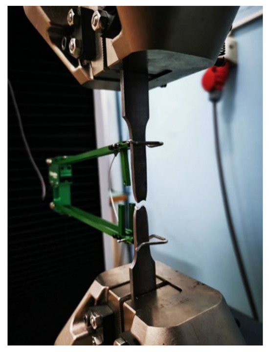
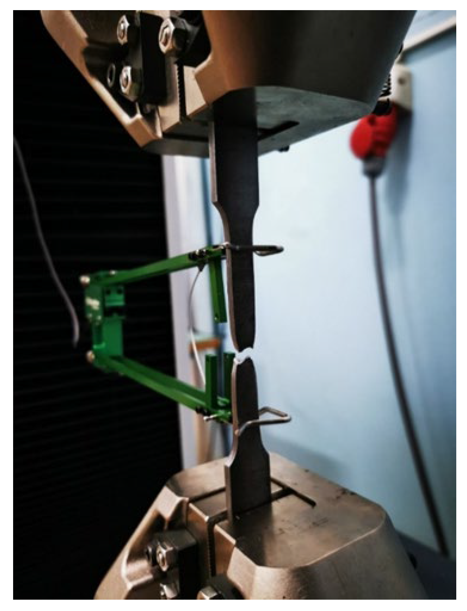
For the standard tensile testing, the Shimadzu AGS-X universal testing machine (Kyoto, Japan) with a maximum load capacity of 100 kN was employed, along with an Axial Extensometer (Model 3542, gauge length 50 mm); see Figure 4. The tests were conducted at a loading speed of 1 mm/min, ensuring compliance with the relevant standard.
Figure 4.
Tensile testing of standard tensile specimens.
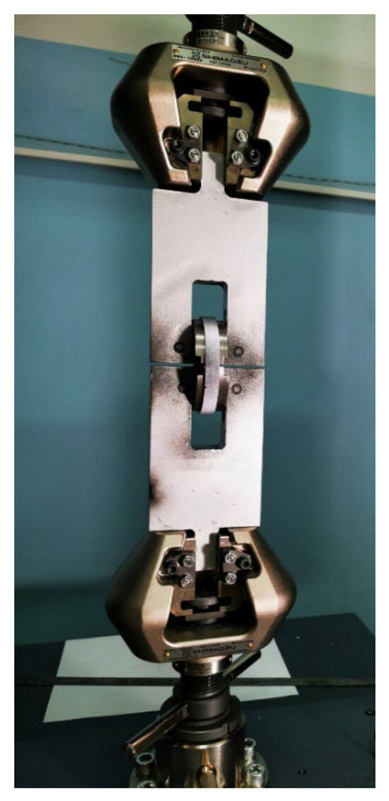
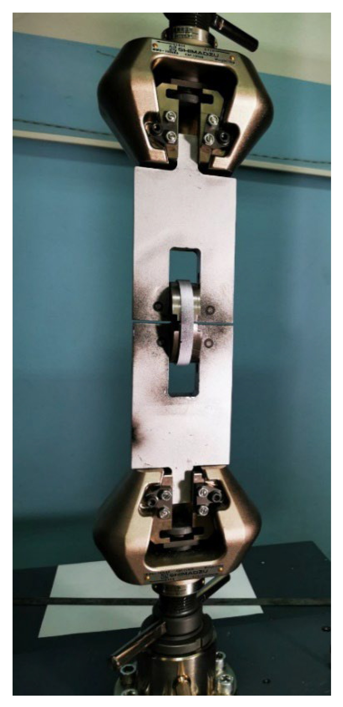
A specially designed and patented tool was used for testing the PRNT specimens. This tool ensures precise loading in the hoop direction and simulates internal pressure conditions (Figure 5). For measuring displacements and calculating strains on the PRNT specimens with a sharp notch, the digital image correlation (DIC) method was used with a 3D stereometric system, Aramis 2M (GOM, Braunschweig, Germany) [21,22,23]. This system proved to be highly reliable for measuring displacements and strains on pressure equipment and during standard testing procedures, as demonstrated in previous studies [16,17].
Figure 5.
PRNT specimen with applied stochastic pattern for measurement by the DIC method.
The dimensional tolerances between the supporting cylinder (D-block) and the PRNT specimen are minimal, within ±0.2 mm, ensuring sufficient clearance for the D-block to fit into the ring while maintaining a secure and repeatable testing setup. This clearance, along with other tolerances within the assembly, primarily affects the initial portion of the force–displacement curve, which appears as a plateau. This plateau represents the stabilization phase of the specimen within the fixture before the actual loading response is recorded.
Numerical analysis using Simulia Abaqus software v. 2018 (Dassault Systèmes, Paris, France) was used to calculate the J-integral and to provide data for the force vs. CMOD (F-CMOD) curves. The conducted analyses are based on the finite element models of half of the PRNT specimen and the D-block model (half-symmetry models). For the purposes of this analysis, the properties of the P235TR1 material obtained from experimental analysis of standard tensile specimens were used. Table 3 shows the dimensions of the models; it can be seen that the crack length is varied.
Table 3.
Dimensions of the PRNT specimen models.
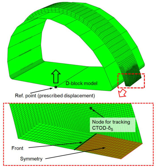
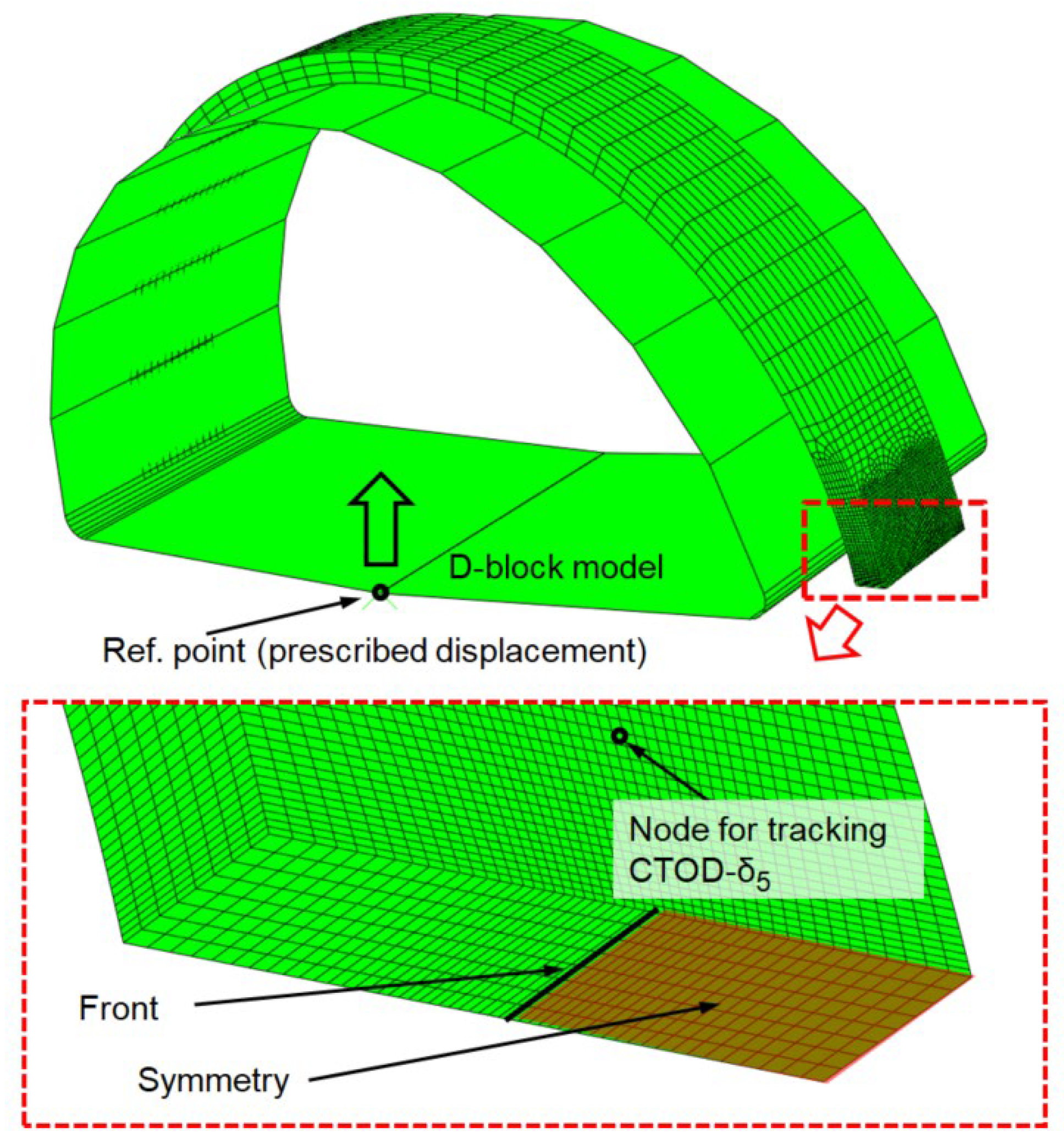
The test tool, or D-block, is modeled as a rigid body, while half of the PRNT test specimen is defined as an isotropic elastic–plastic component. The mesh is defined with quadratic (20 nodes) finite elements with reduced integration. In the zone of interest (around the crack), mesh is refined with elements of size 0.15 mm, Figure 6.
Figure 6.
The FE model of the PRNT specimen and D-block for load application.
To ensure the accuracy and reliability of the numerical results, a mesh convergence study was conducted. The study involved sequentially refining the mesh by using element sizes of 0.3 mm, 0.25 mm, 0.2 mm, and finally 0.15 mm. The J-integral values were compared at each refinement step, and the difference between the results obtained with 0.15 mm and 0.2 mm element sizes was found to be below 5%. Based on this, the element size of 0.15 mm around the crack was deemed appropriate, balancing computational efficiency and result accuracy.
For the model load to simulate the load applied during the experimental test, the displacement of the D-block in the Y direction (in the direction of the load) was set to 2 mm. Displacements in other directions are disabled. Based on the definition of the length of the crack, the symmetry conditions are also defined. On the cross-sectional surface of the PRNT model, symmetry is defined on those surfaces that do not belong to the initial length of the crack.
3. Results and Discussion
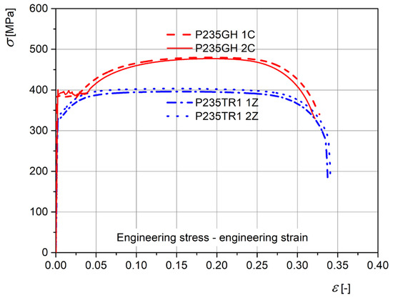
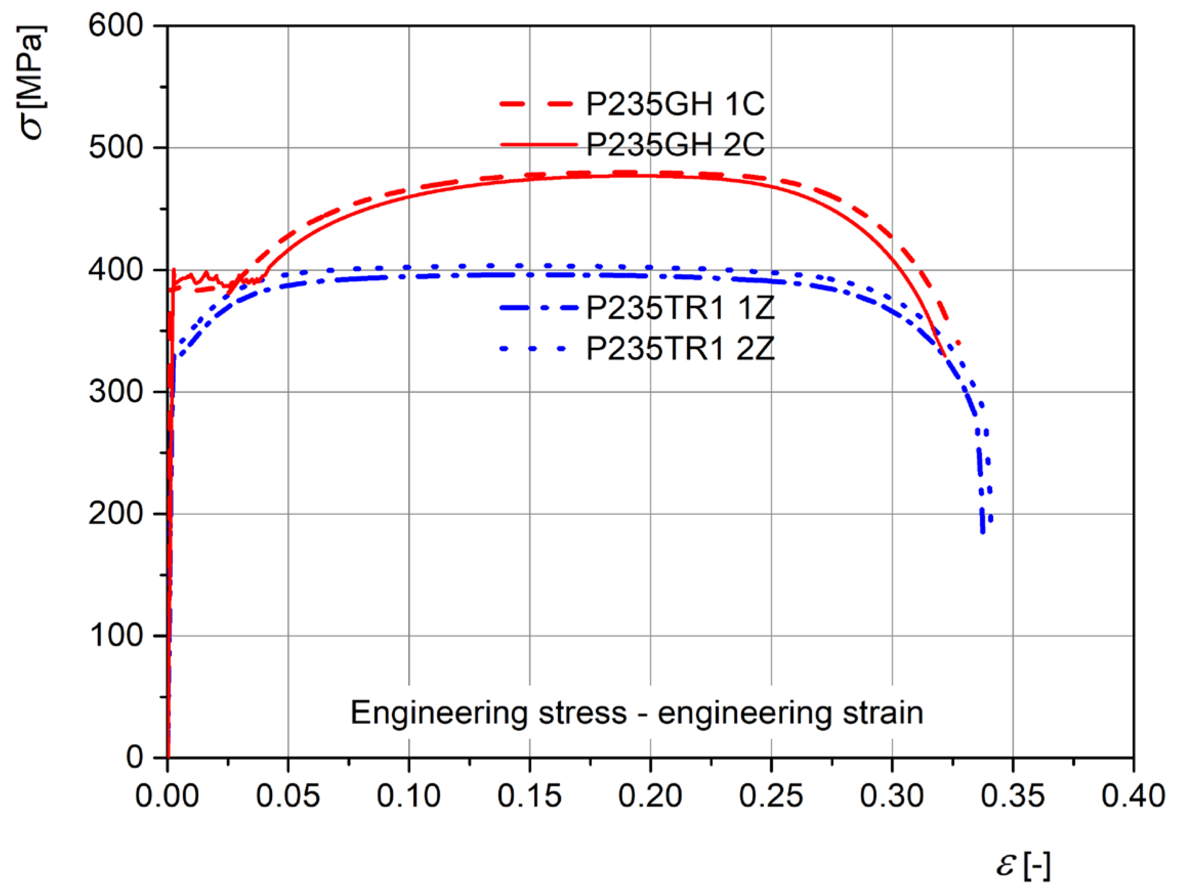
Tensile stress–strain curves are shown in Figure 7 for the specimens made of seamless pipes (P235GH steel), which are shown for comparison purposes only, since they are not used in the analysis presented here, as well as for the seam pipes made of P235TR1 steel, which are used as the input data for the finite element calculations. Relevant yield strength (Rp0.2) and tensile strength (Rm) values are 330 MPa and 402 MPa, respectively. The modulus of elasticity is 180 GPa, and Poisson’s ratio is 0.3.
Figure 7.
Dependence of stress on strain for P235TR1 and P235GH material.
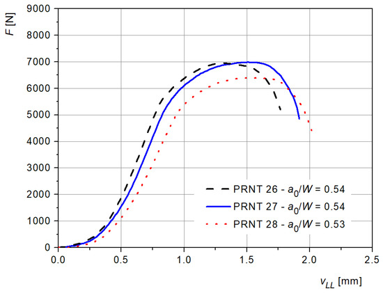
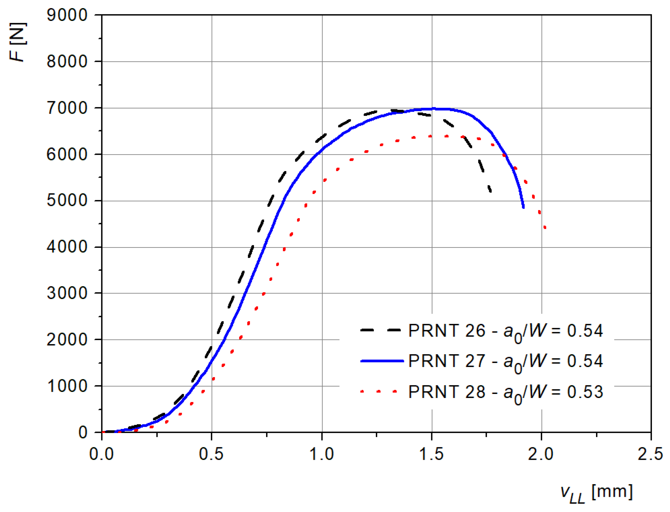
By testing the three PRNT specimens with an approximately same ratio of sharp notch length to specimen width, force–displacement curves were obtained and are shown in Figure 8. The results indicate relatively good repeatability, and the diagrams are presented without modifications. The small force increments within the first 0.3 mm are a result of the stabilization of the PRNT specimen on the D-block of the testing tool (establishing the contact between the tool and the specimen). This phenomenon is observed in all three specimens and can be considered a consistent behavior for the tested geometry.
Figure 8.
Dependence of force on load line displacement-P235TR1 PRNT specimens.
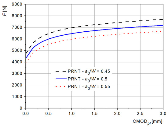
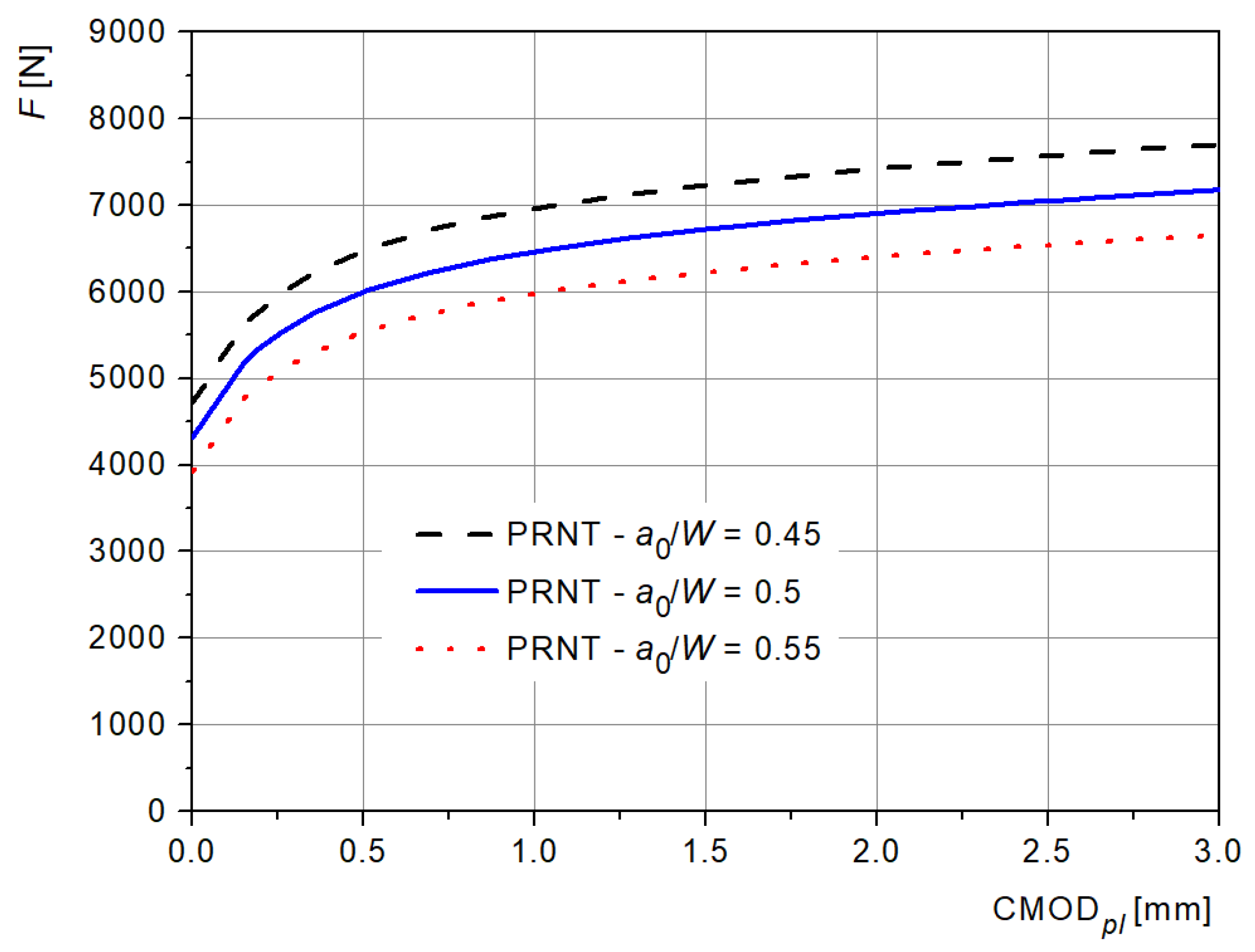
In the following figures, results obtained from numerical models of PRNT specimens with sharp notches are presented; material P235TR1 is considered. Figure 9 shows the results of the dependence of the force on the plastic component of the crack mouth opening displacement (CMOD) for three models with different initial crack lengths. It is important to mention that this diagram corresponds to three a0/W ratios: 0.45, 0.5, and 0.55, just to present the general influence of this ratio on results. However, two more ratios were used for the calculation of ηpl, which will be emphasized later.
Figure 9.
Dependence of force on the plastic component of the CMOD-models of PRNT specimens with P235TR1 material properties.
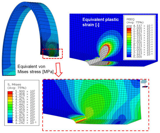
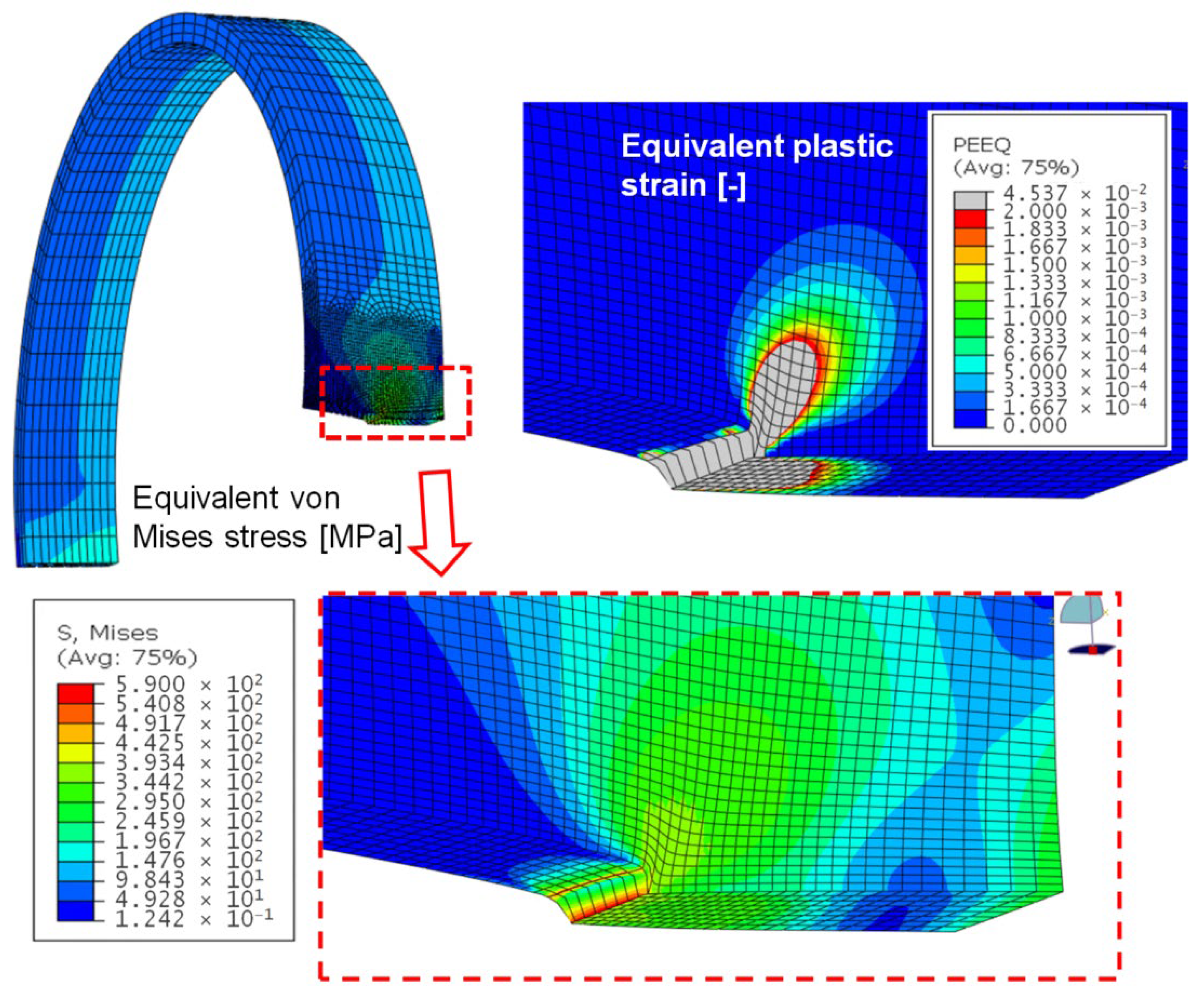
The distribution of the equivalent von Mises stress and equivalent plastic strain are shown in Figure 10; the concentration of both quantities is very pronounced in the zone of the crack front, as expected.
Figure 10.
Distribution of the equivalent von Mises stress and equivalent plastic strain on the PRNT model with P235TR1 material properties.
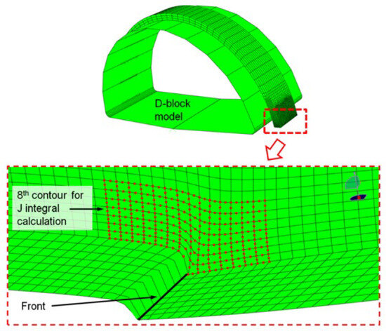
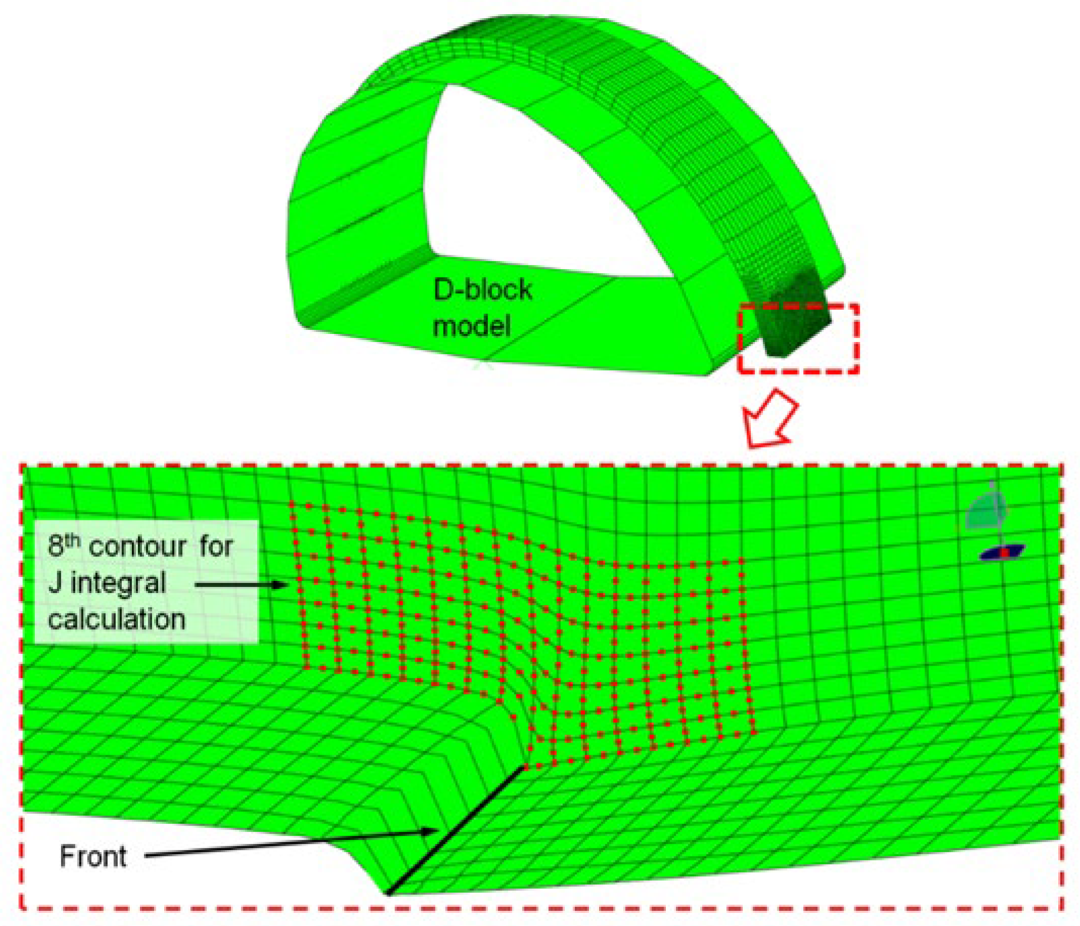
The J-integral was extracted from the finite element models by application of the domain integral method in Simulia Abaqus. Figure 11 shows the eighth contour, which was applied in the analysis as sufficient for obtaining convergent results, i.e., the J-integral values. It is important to note that the figure contains only the contour on the surface of the specimen. However, the values of the J-integral are determined from all contours, on the surface and inside the material along the entire crack front, and the maximum value is taken as appropriate. In all analyzed models, the J-integral values were extracted from the third layer from the inner wall towards the outer surface, as this layer exhibited the highest J-integral values across the entire crack front.
Figure 11.
Contour No. eight for calculation of the J-integral on the surface of the PRNT model.
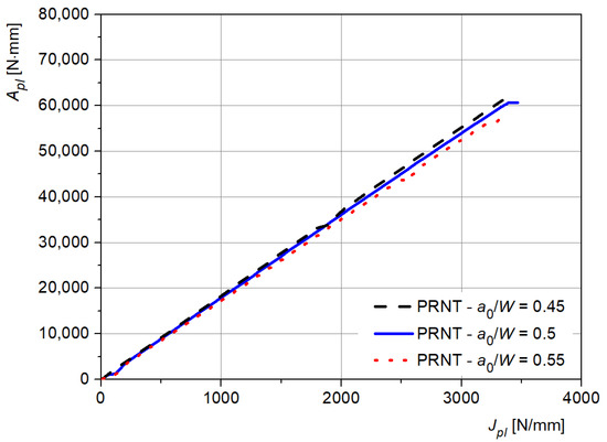
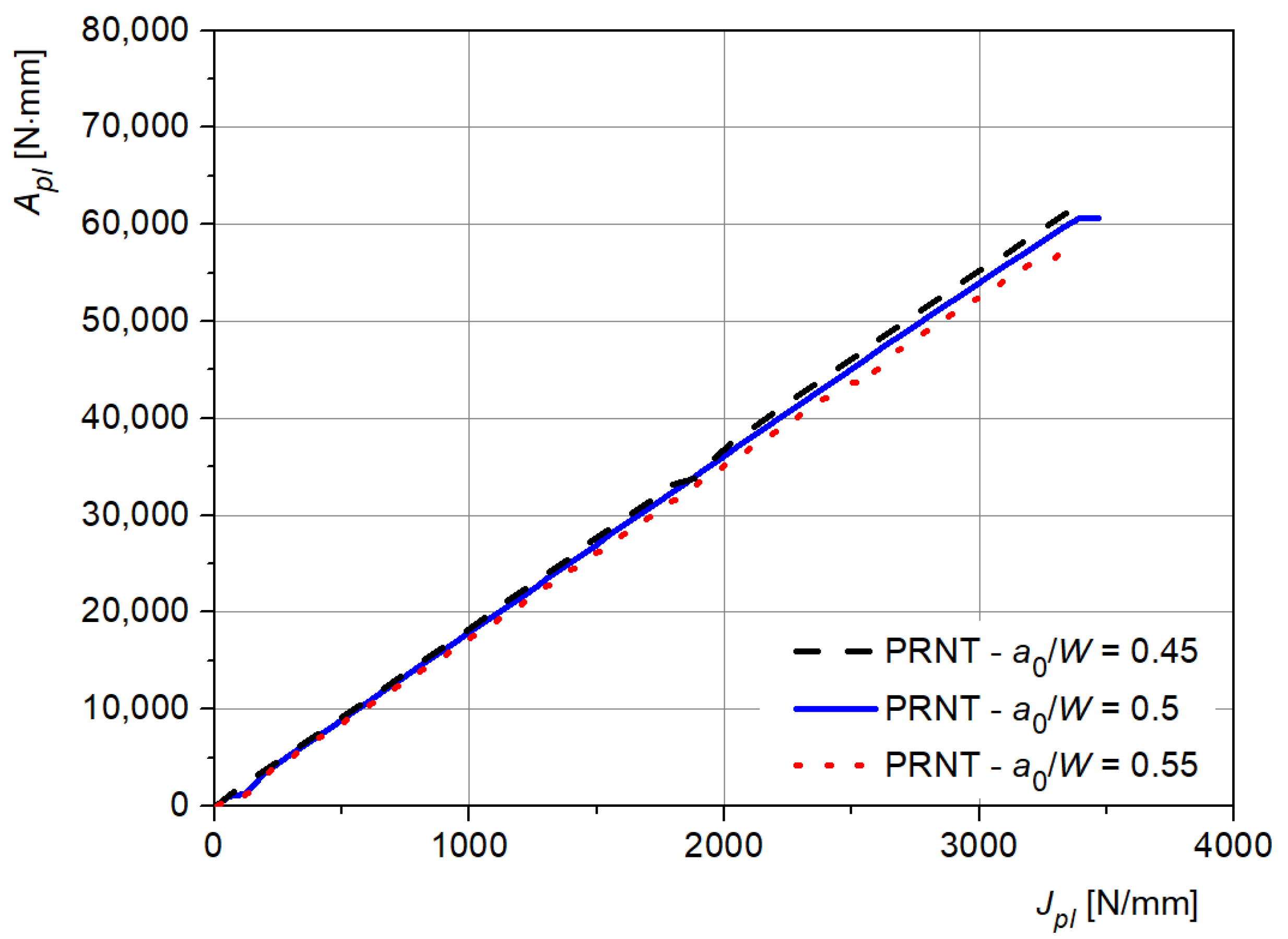
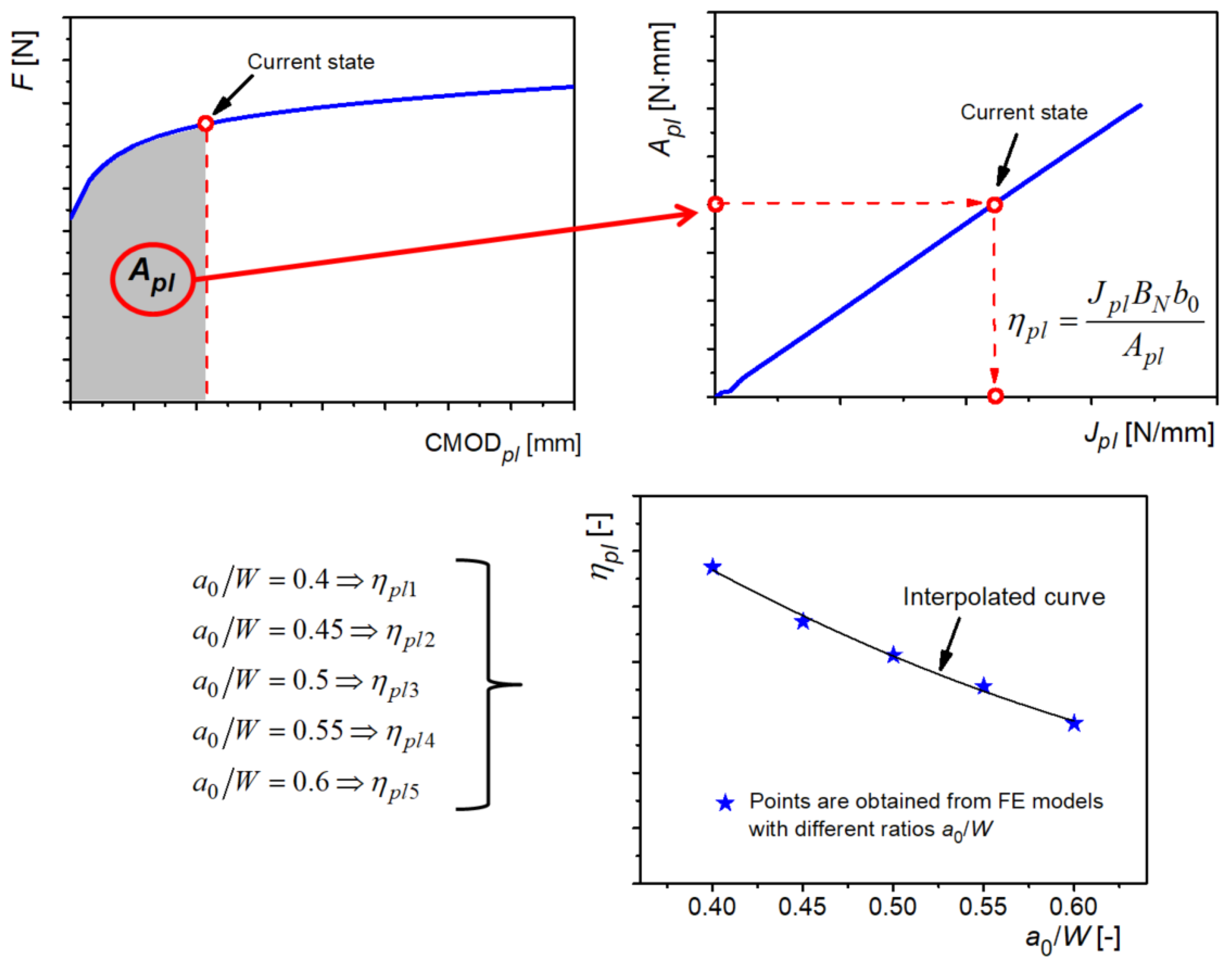
Next, the dependence of the surface area Apl on the plastic component of the J-integral is extracted from the series of models with different crack lengths, Figure 12. The area Apl is determined from the curve F-CMODpl, i.e., from the dependence of force on the plastic component of the CMOD, Figure 12.
Figure 12.
Dependence of the area Apl on the plastic component of the J-integral for PRNT specimens with different ratios a0/W.
The geometric coefficient ηpl determination procedure is based on the well-known Equation (1).
where b0 is initial length of the ligament, ηpl is geometric coefficient, Apl is area under the curve F-CMODpl (Figure 13), and BN is reduced specimen thickness. In this case, it is equal to the specimen thickness B; this value can be smaller than B in case the side grooves are fabricated, which is sometimes performed for thick specimens.
Figure 13.
Graphical overview of the procedure for determination of ηpl and its dependence on a0/W from the results of numerical analysis.
This equation is typically used for the calculation of the plastic component of the J-integral for standard specimen geometries, such as CT or SENB. For these specimens, the value of the geometric coefficient can be determined in accordance with standard procedures. However, this relation is used in a different manner here, Equation (2), to determine the coefficient ηpl for the PRNT specimen with different crack lengths, based on the numerically determined values of Jpl and Apl.
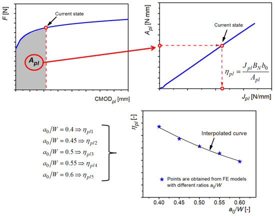
Figure 13 contains a general graphical overview of the applied procedure. The starting point is the diagram F-CMODpl obtained from the numerical model of a PRNT specimen. For a selected point on this diagram, one can calculate the surface area Apl, shaded in Figure 13. In this way, dependence of this surface area on the plastic component of the J-integral can be formed. From Equation (2), it can be seen that this diagram can be used to calculate ηpl. Further, when the same procedure is repeated for different a0/W ratios, the dependence of ηpl on a0/W is obtained. The points corresponding to each a0/W ratio are marked by symbols on the diagram, and finally a quadratic interpolation curve is fitted.
The values of the geometric coefficient ηpl for all the five a0/W ratios used in this study, determined by the procedure illustrated in Figure 13, are shown in Table 4. One detail should be emphasized here: the values in the table are determined for a single value of the plastic component of the J-integral (1300 N/mm). Varying this value (2000 and 3200 N/mm) gave almost no difference. This can be seen as a consequence of the linear shape of each line in Figure 12; determination of the slope from the diagram gives almost identical results as Table 4 (deviation is less than 1%). Essentially, this means that ηpl can be considered as independent on the J-integral value and therefore also independent on the loading level, which is very important for practical application.
Table 4.
Values of geometric parameter ηpl for different values of a0/W and Jpl = 1300 N/mm.
According to the values of geometric factor ηpl one can make the following relation with the ratio a0/W:
which can be used to calculate the geometric factor ηpl values in the range of ratios a0/W (0.4 ÷ 0.6).
The obtained relationship between the geometric factor ηpl and the ratio a0/W follows a predictable trend. Specifically, as the ratio a0/W increases, the value of ηpl exhibits a decrease, which aligns with trends observed in some previous studies on fracture mechanics specimens. However, the values and trends in the literature (e.g., [24,25,26,27,28]) are not the same, or even comparable among them, keeping in mind that the geometric factor strongly depends on the specimen geometry.
Future research will focus on determining the material fracture resistance curve through additional experimental investigations and numerical simulations, considering variations in specimen thickness, width, and diameter. In addition, it should be mentioned that the determination of parameters influencing the J integral for non-standard geometries is very problematic to explicitly validate. There is a possibility to verify the numerical model itself by using some damage model (e.g., Gurson–Tvergaard–Needleman model GTN [29,30], or complete Gurson model CGM [31]) for comparison to the experiment, which might be an interesting topic for future analyses.
4. Conclusions
The results of this study demonstrated that numerical simulation can be used efficiently to evaluate the geometric factor ηpl in the case of non-standard ring shape specimens. Based on the finite element method results, the relation between the geometric factor ηpl and the ratio of crack length and specimen width, a0/W, is obtained, which can be used to interpolate the values of ηpl in the range of a0/W from 0.4 to 0.6 for the analyzed pipe geometry. In this way, a non-standard ring-shaped specimen (PRNT) becomes relevant for testing the pipeline materials, enabling better understanding of material behavior in real conditions.
The results obtained on a selected set of pipe ring geometries provide a significant contribution to understanding the behavior of thin-walled pipeline materials under loading, forming a foundation for the further development of integrity and safety assessment methods in industrial applications.
In further research, the presented procedure will be extended to the models in which pipe dimensions will be varied. Using a wider range of a0/W ratios and different sizes of the proposed specimens will allow an extension of the application range of this method to different types of thin-walled pipelines. This will provide flexibility and adaptability in industrial application. In addition, the influence of material properties will be examined, to cover the materials used in different industry branches, e.g., high-strength steels and stainless steels. Having in mind different fracture behaviors of these materials, another improvement might be application of some damage model in numerical studies.
Author Contributions
Conceptualization, Z.R., M.M. and B.M.; methodology, B.M.; software, I.T., J.T. and B.M.; validation, J.T. and B.M.; formal analysis, J.L.; investigation, I.T., J.T. and Z.R.; resources, Z.R. and M.M.; data curation, I.T.; writing—original draft, I.T.; writing—review and editing, Z.R., B.M., and J.L.; visualization, I.T. and J.T.; supervision, M.M. and B.M.; project administration, J.L.; funding acquisition, J.L. All authors have read and agreed to the published version of the manuscript.
Funding
We acknowledge Open Access Funding by FH Campus Wien, University of Applied Sciences, Vienna, Austria. This research was supported by the Ministry of Science, Technological Development and Innovation of the Republic of Serbia (contr. 451-03-136/2025-03/200213, 451-03-136/2025-03/200135, and 451-03-137/2025-03/200105).
Data Availability Statement
The original contributions presented in this study are included in the article. Further inquiries can be directed to the corresponding author.
Acknowledgments
This paper is dedicated to the late Marko Rakin (1966–2023), who was an integral part and driving force of this research. The authors of this paper would like to express their gratitude to the Ministry of Education, Science, and Technological Development, The Republic of Serbia, for supporting our research.
Conflicts of Interest
The authors declare no conflicts of interest.
Nomenclature (Alphabetical Order)
| a0 | Initial crack length [mm] |
| a0/W | Ratio of initial crack length to specimen width [%] |
| Apl | Area under the force–displacement curve [N·mm] |
| Aramis GOM 2M | Optical measurement system for DIC analysis |
| B | Specimen thickness [mm] |
| b0 | Ligament length [mm] |
| BN | Reduced specimen thickness [mm] |
| CMOD | Crack mouth opening displacement |
| CP | Compact pipe specimen |
| CT | Compact tension specimen |
| CTOD | Crack tip opening displacement |
| D | Inner diameter of the specimen [mm] |
| DIC | Digital image correlation |
| FEM | Finite element method |
| J-integral | Contour integral used in fracture mechanics to quantify energy release rate [J/m2 or N/mm] |
| KI | Mode I stress intensity factor [MPa√m] |
| ηpl | Plastic geometry factor |
| P235TR1, P235GH | Pipeline steel materials used in the study |
| PLT | Pin loading tension test |
| PRNB | Pipe ring notched bending specimen |
| PRNT | Pipe ring notched tension specimen |
| SENB | Single edge notched bending specimen |
| SENT | Single edge notched tension specimen |
| SLS | Selective laser sintering |
| Rm | Ultimate tensile strength [MPa] |
| Rp0.2 | Yield strength (0.2% offset) [MPa] |
| vLL | Load-line displacement [mm] |
| W | Specimen width [mm] |
References
- Mahajan, G.; Saxena, S.; Mohanty, A. Numerical characterization of compact pipe specimen for stretch zone width assessment. Fatigue Fract. Eng. Mater. Struct. 2016, 32, 859–865. [Google Scholar] [CrossRef] [Scilit]
- Bergant, M.; Yawny, A.; Perez Ipiña, J. Experimental determination of J-resistance curves of nuclear steam generator tubes. Eng. Fract. Mech. 2016, 164, 1–18. [Google Scholar] [CrossRef] [Scilit]
- Gajdos, L.; Sperl, M. Evaluating the integrity of pressure pipelines by fracture mechanics. In Applied Fracture Mechanics; Belov, A., Ed.; IntechOpen: London, UK, 2012; pp. 283–310. [Google Scholar] [CrossRef] [Scilit]
- Koo, J.M.; Park, S.; Seok, C.S. Evaluation of fracture toughness of nuclear piping using real pipe and tensile compact pipe specimens. Nucl. Eng. Des. 2013, 259, 198–204. [Google Scholar] [CrossRef] [Scilit]
- Rais, B.; Garnier, J.; Pons, E.; Marini, B.; Besson, J. Determination of the fracture toughness of a 9Cr ODS steel fuel cladding using the pin loading Tension test. Eng. Fract. Mech. 2023, 290, 109499. [Google Scholar] [CrossRef] [Scilit]
- Sanyal, G.; Samal, M.K.; Chakravartty, J.K.; Suri, A.K. Prediction of J–R curves of thin-walled fuel pin specimens in a PLT setup. Eng. Fract. Mech. 2011, 78, 1029–1043. [Google Scholar] [CrossRef] [Scilit]
- Boot, T.; Reimslag, T.; Reinton, E.; Liu, P.; Walters, C.; Popovich, V. In-situ hollow sample setup design for mechanical characterisation of gaseous hydrogen embrittlement of pipeline steels and welds. Metals 2021, 11, 1242. [Google Scholar] [CrossRef] [Scilit]
- Rodolfo, A., Jr.; Vanderely, J. Application of fracture mechanics for the characterization of poly(vinyl chloride) pipes. II. Evaluation of a ring-type specimen for fracture mechanics testing. J. Vinyl Addit. Technol. 2021, 27, 806–820. [Google Scholar] [CrossRef] [Scilit]
- Matvienko, Y.G.; Gubeljak, N. Model for Determination of Crack-Resistance of the Pipes. Patent No. RU 2564696 C, 10 October 2015. (In Russian) [Google Scholar]
- Gubeljak, N.; Likeb, A.; Matvienko, Y. Fracture toughness measurement by using pipe-ring specimens. Procedia Mater. Sci. 2014, 3, 1934–1940. [Google Scholar] [CrossRef] [Scilit]
- Musrati, W.; Medjo, B.; Gubeljak, N.; Štefane, P.; Veljić, D.; Sedmak, A.; Rakin, M. Fracture assessment of seam and seamless steel pipes by application of the ring-shaped bending specimens. Theor. Appl. Fract. Mech. 2019, 103, 102302. [Google Scholar] [CrossRef] [Scilit]
- Damjanović, D.; Kozak, D.; Gelo, I.; Gubeljak, N. The influence of torsion effect on fracture behavior of Pipe Ring Notched Bend specimen (PRNB). Theor. Appl. Fract. Mech. 2019, 103, 102286. [Google Scholar] [CrossRef] [Scilit]
- Damjanović, D.; Kozak, D.; Gubeljak, N. The influence of residual stresses on fracture behavior of Pipe Ring Notched Bend specimen (PRNB). Eng. Fract. Mech. 2019, 205, 347–358. [Google Scholar] [CrossRef] [Scilit]
- Travica, M.; Mitrović, N.; Petrović, A.; Trajković, I.; Milošević, M.; Sedmak, A.; Berto, F. Experimental evaluation of hoop stress–strain state of 3D-printed pipe ring tensile specimens. Metals 2022, 12, 1560. [Google Scholar] [CrossRef] [Scilit]
- Kim, S.; Eom, T.; Lee, W.; Choi, S. Tapered waist tensile specimens for evaluating butt fusion joints of polyethylene pipes—Part 1: Development. Polymers 2022, 14, 1187. [Google Scholar] [CrossRef] [Scilit] [PubMed]
- Trajković, I.; Ranik, M.; Milošević, M.; Mitrović, N.; Travica, M.; Sedmak, A.; Medjo, B. Selective laser sintered Pipe Ring Notched Tension specimens for examination of fracture properties of pipeline materials. Eng. Fract. Mech. 2023, 292, 109573. [Google Scholar] [CrossRef] [Scilit]
- Trajković, I.; Milošević, M.; Travica, M.; Rakin, M.; Mladenović, G.; Kurdjavceva, L.; Medjo, B. Novel method for measurement of pipeline materials fracture resistance-examination on selective laser sintered cylindrical specimens. Sci. Sinter. 2022, 54, 373–386. [Google Scholar] [CrossRef] [Scilit]
- Sedmak, A. Fatigue crack growth simulation by extended finite element method: A review of case studies. Fatigue Fract. Eng. Mater. Struct. 2024, 47, 1819–1855. [Google Scholar] [CrossRef] [Scilit]
- Sedmak, A. Computational fracture mechanics: An overview from early efforts to recent achievements. Fatigue Fract. Eng. Mater. Struct. 2018, 41, 2438–2474. [Google Scholar] [CrossRef] [Scilit]
- ASTM E8/E8M-22; Standard Test Methods for Tension Testing of Metallic Materials. ASTM International: West Conshohocken, PA, USA, 2022.
- Škrlec, A.; Panić, B.; Nagode, M.; Klemenc, J. Estimating the Cowper–Symonds parameters for high-strength steel using DIC combined with integral measures of deviation. Experimental and numerical investigation of compression behavior in steel structures. Metals 2024, 14, 992. [Google Scholar] [CrossRef] [Scilit]
- Jonsson, S.; Kajberg, J. Evaluation of crashworthiness using high-speed imaging, 3D digital image correlation, and finite element analysis, mechanical behaviors and damage mechanisms of metallic materials. Metals 2024, 13, 1834. [Google Scholar] [CrossRef] [Scilit]
- Paulsen, C.O.; Fagerholt, E.; Borvik, T.; Westermann, I. Comparing in situ DIC results from an etched surface with a gold speckled surface, quasi-static and dynamic testing of metallic materials. Metals 2019, 9, 820. [Google Scholar] [CrossRef] [Scilit]
- Carvalho, H.S.S.; Ruggieri, C. Significance of the plastic eta factor in J estimation procedures for tensile SE(T) fracture specimens. In Proceedings of the PVP2010 ASME Pressure Vessels and Piping Conference, Bellevue, WA, USA, 18–22 July 2010. [Google Scholar] [CrossRef] [Scilit]
- Ruggieri, C. Further results in J and CTOD estimation procedures for SE(T) fracture specimens–Part I: Homogeneous materials. Eng. Fract. Mech. 2012, 79, 245–265. [Google Scholar] [CrossRef] [Scilit]
- Wang, E.; De Waele, W.; Hertelé, S. A complementary ηpl approach in J and CTOD estimations for clamped SENT specimens. Eng. Fract. Mech. 2015, 147, 36–54. [Google Scholar] [CrossRef] [Scilit]
- Tian, Y.; Zhang, S.; Wang, X.; Shuai, Y.; Yhang, T.; Duo, Y. Study on J-integral plasticity factor of high-grade pipeline girth welded joints based on SENT specimen. Int. J. Press. Vessels Pip. 2025, 214, 105419. [Google Scholar] [CrossRef] [Scilit]
- Bind, A.K.; Singh, R.N. Relation of ηpl and γpl with separation parameter (S) and their usefulness for fracture toughness evaluation. Eng. Fract. Mech. 2023, 289, 109487. [Google Scholar] [CrossRef] [Scilit]
- Gurson, A.L. Continuum theory of ductile rupture by void nucleation and growth: Part I–yield criteria and flow rules for porous ductile media. J. Eng. Mater.-Trans. ASME 1977, 99, 2–15. [Google Scholar] [CrossRef] [Scilit]
- Tvergaard, V.; Needleman, A. Analysis of cup-cone fracture in a round tensile bar. Acta Metall. 1984, 32, 157–169. [Google Scholar] [CrossRef] [Scilit]
- Zhang, Z.L.; Thaulow, C.; Odegard, J. A complete Gurson model approach for ductile fracture. Eng. Fract. Mech. 2000, 67, 155–168. [Google Scholar] [CrossRef] [Scilit]

Disclaimer/Publisher’s Note: The statements, opinions and data contained in all publications are solely those of the individual author(s) and contributor(s) and not of MDPI and/or the editor(s). MDPI and/or the editor(s) disclaim responsibility for any injury to people or property resulting from any ideas, methods, instructions or products referred to in the content. |
© 2025 by the authors. Licensee MDPI, Basel, Switzerland. This article is an open access article distributed under the terms and conditions of the Creative Commons Attribution (CC BY) license (https://creativecommons.org/licenses/by/4.0/).