


Abstract
A three-dimensional thermo-elasto-hydrodynamic (TEHD) lubrication model is presented for the high-pressure deep-grooved mechanical seal employed. The thermo-elasto deformation behaviors of the seal rings are investigated using the finite element method (FEM). The parametric studies are conducted to explore the deformation characteristics of the seal face and sealing performance under different operating conditions. The results reveal that the deep-grooved face seal induces circumferential waviness deformation of the seal face, generating the hydrodynamic wedge effect dominated by the axial mechanical deformation along the circumferential direction. However, a significant hydrostatic effect produced by the deformation of the seal face along the radial direction is dominant in the load-carrying capacity of the fluid film. The thermo-mechanical coupling deformation of the seal face decreases with increasing fluid pressure and increases as the spring force and rotational speed increase. The leakage rate increases with higher fluid pressure, while it decreases with increased spring force and rotational speed. The axial stiffness of the fluid film increases with greater spring force and rotational speed but decreases with increasing fluid pressure. These findings can serve as theoretical guidance for developing high-pressure deep-grooved mechanical seals with enhanced reliability and stability.
1. Introduction
Currently, mechanical seals typically employ non-contact patterns, among which the deep-grooved mechanical seal with millimeter-scale hydrodynamic grooves on the end face is one of the common configurations for high-pressure duties [1,2]. Although deep-grooved mechanical seals possess favorable performance characteristics, the traditional theory of hydrodynamic lubrication fails to evaluate the internal fluid flow state within the grooves and the influence of flow in the grooves on heat transfer due to their complex working mechanisms. Additionally, viscous shear heat generated by the fluid film causes the temperature rise in the seal rings, resulting in the thermal deformation of the seal rings, while the higher pressure causes the mechanical deformation of the seal rings. Based on the thermo-mechanical coupling deformation, the deep-grooved mechanical seal operates in a thermo-elasto-hydrodynamic (TEHD) lubrication state. In this state, the sealing clearance changes and generates a thermo-hydrodynamic wedge effect that greatly influences the sealing performance. Therefore, the thermo-mechanical coupling deformation of the seal face plays a critical role in determining the sealing performance.
Based on the TEHD theory, the deformation characteristics of the seal face for mechanical seals have been investigated by many researchers. Li [3] studied the thermo-mechanical coupling deformation of the seal rings numerically and found that the thermal deformation is more significant than the mechanical deformation. However, this study only considered two-dimensional deformation. Blasiak et al. [4] proposed an analytical approach to study the thermal distortions of the non-contacted face seals. Nyemeck et al. [5] studied the thermal effect and deformation of the mechanical seals based on the mixed TEHD lubrication analysis. Brunetière et al. [6,7] investigated the TEHD lubrication of mechanical face seals through numerical and experimental methods and found that the thermal characteristics are mainly influenced by the deformation of the seal rings. Thomas et al. [8] studied the TEHD behavior of mechanical gas face seals operating at high pressure and revealed that the mechanical distortions of the seal face led to a converging gap. The thermo-mechanical coupling deformation of the seal rings plays a great part in the radial taper and sealing performance. The above-mentioned studies mainly concentrate on the axisymmetric deformation behavior of the mechanical seals, and the influence of the circumferential variation is not considered. To further investigate the deformation and sealing performance of the deep-grooved mechanical seals, scholars developed the three-dimensional (3D) TEHD model for evaluation. Mayer [1] attributed the long-term stable operation of grooved mechanical seals under high-pressure conditions to the strong cooling effect generated by the grooves, called the thermo-hydrodynamic wedge effect. This leads to non-uniform thermal deformation of the sealing rings, resulting in the formation of periodically distributed waviness of the seal face. Meng et al. [9] developed a 3D TEHD model to evaluate the sealing performance of the notched mechanical seal, and the results showed that the notch can cool the fluid film and influence the thermal deformation of the seal rings. Yang et al. [10] investigated the sealing performance of mechanical seals with triangular grooves under mixed lubrication conditions based on the 3-D TEHD model, and the results show that the deformation of the seal face has a significant influence on the sealing performance. Djamai et al. [11] investigated the TEHD lubrication mechanism of a mechanical seal with semi-circular grooves and concluded that the grooves induce waviness on the end faces of both the rotor and stator. Liu et al. [12,13] studied the sealing performance of a wavy-tilt-dam mechanical seal using the 3D TEHD model and concluded that the thermal deformation has little influence on the symmetry of the waviness. Although scholars have conducted extensive research on deep-grooved mechanical seals, the lubrication mechanisms based on the TEHD model have not yet been fully revealed in the high-pressure environment, and further in-depth research on the mechanism and thermo-mechanical coupling deformation characteristics remains necessary. This is of significant importance for improving the sealing performance and reliability of high-pressure deep-grooved mechanical seals.
In this paper, a 3-D TEHD model is presented for a high-pressure deep-grooved mechanical seal. Based on this model, the deformation characteristics of the seal face and sealing performance are investigated by using the finite element method (FEM) under different operating conditions. The results provide new guidance for the design and development of high-pressure deep-grooved mechanical seals with high reliability and stability.
2. Materials and Methods
2.1. Geometric Model
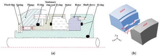
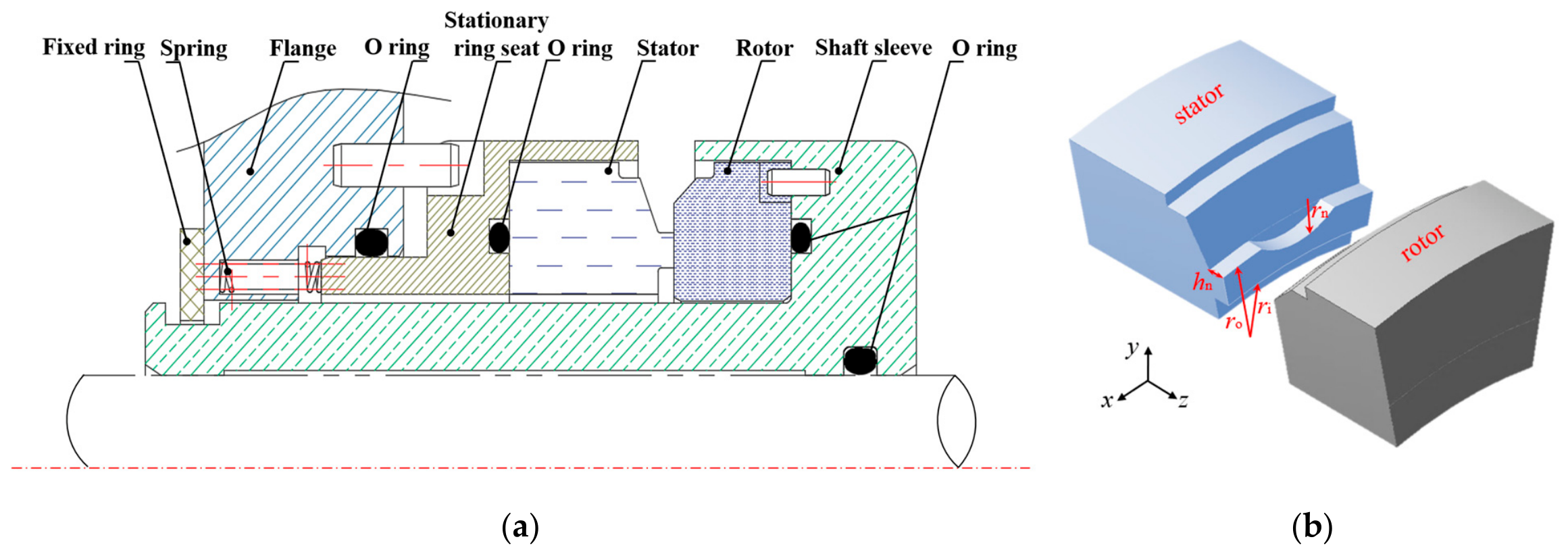
The periodic geometric model shown in Figure 1 is adopted as the computational domain due to the axisymmetric characteristics of the mechanical seal ring. The model includes a rotor, a stator, and the fluid film between the seal end faces. There is a semi-circular deep groove on the end face of the stator. The main structural parameters of the geometric model and operating conditions are presented in Table 1. All pressures are absolute pressures.
Figure 1.
Diagram of the geometric model. (a) Assembly diagram of the mechanical seal; (b) Periodic geometric model of the seal rings.
Table 1.
Geometrical parameters and operating conditions.
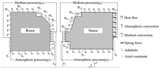
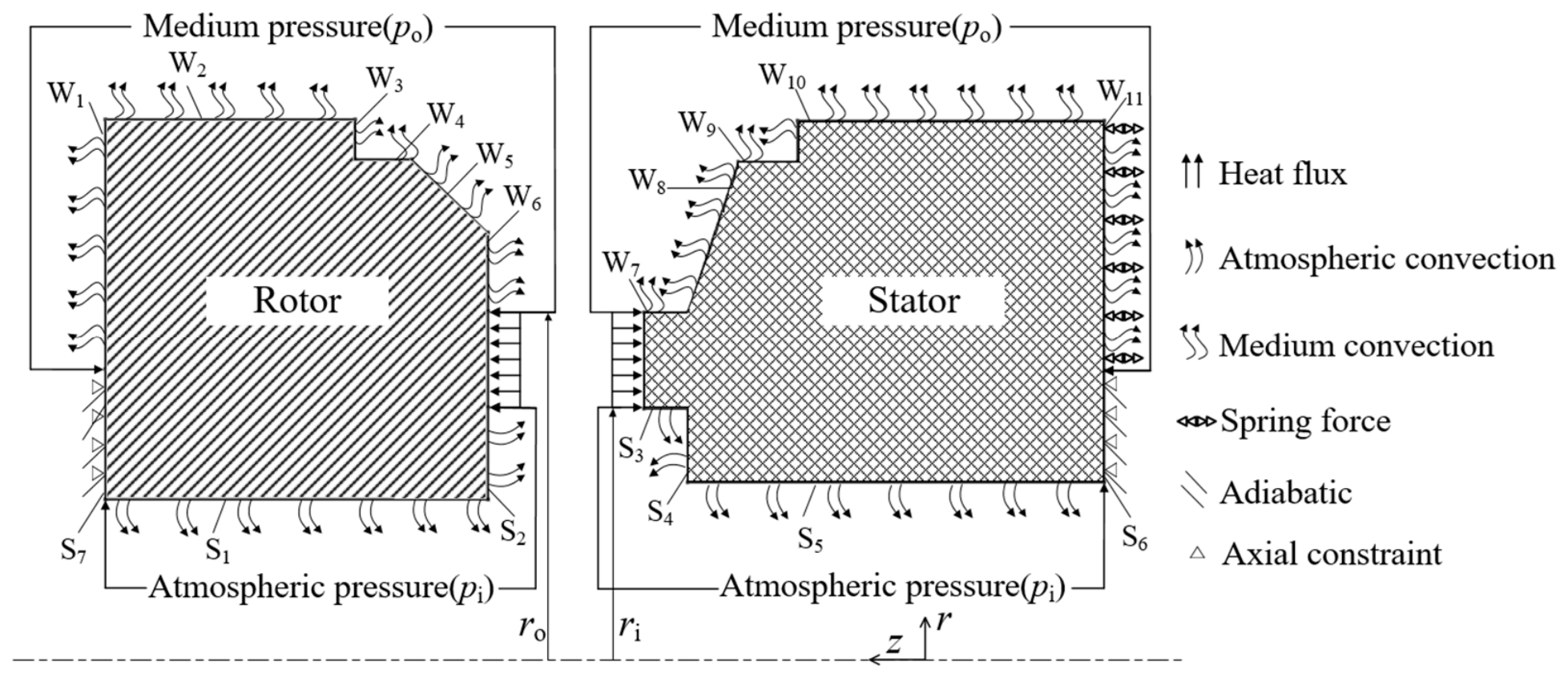
Figure 2 presents the specific boundary conditions of the seal rings. The stator, as a primary ring, is in close contact with the rotor under the action of the spring force and the fluid pressure po. The inner surfaces (S1–S5) of the seal rings are in direct contact with the atmosphere (pi is presented as atmospheric pressure), and the outer surfaces (W1–W11) of the seal rings are in direct contact with the fluid medium. The seal faces are affected by the fluid film pressure and heat flux. The convective heat transfer on the outer surfaces of the rotor is relatively large, whereas that on the inner surfaces of the rotor is comparatively small. Note that an O-ring is set at the outer side of the rotor and stator to prevent high-pressure fluid leakage; thus, the adiabatic boundary is adopted on the surfaces (S6 and S7) of the seal rings. The spring force in the form of spring specific pressure is applied on the backside of the stator, and the axial constraint is imposed on the bottom surfaces of the stator and rotor.
Figure 2.
Boundary conditions of the seal rings.
The materials of the rotor and stator are nickel-bonded tungsten carbide (YWN8, China) and recrystallized silicon carbide (RSiC, China), respectively. The detailed material properties of the rotor and stator are listed in Table 2. The fluid medium is water at a temperature of 300 K.
Table 2.
Properties of the seal ring and fluid medium.
2.2. Mathematical Model
The following assumptions are adopted in the mathematical model presented in the paper: (1) The fluid flow is assumed to be in the laminar state, and the fluid inertial effect is neglected; (2) The heat radiation is not considered in the heat transfer model; (3) The seal face is ideally smooth, and the surface roughness of the seal ring is ignored; (4) The rotor is in alignment with the stator, and the operation is in steady conditions.
2.2.1. Generalized Reynolds Equation
The generalized Reynolds equation with the film cavitation effect is employed to determine the pressure distribution of the fluid film in this study, as expressed below:
where p is the fluid film pressure, pc is the cavitation pressure of the fluid film, U is the local velocity of the end face of the rotor, κ is the density ratio of the fluid film, h is the fluid film thickness, gL and fL are the intermediate variables mainly influenced by viscosity in the lubrication equation of the fluid film, ρ is the local density of the fluid film, ρF is the density of the fluid film, and κ, gL, and fL can be described as follows:
where y indicates the height value at different positions of the fluid film; s is a coefficient taking values of 0, 1, and 2, respectively; µF is the fluid dynamic viscosity and is determined by (4) [14], where a, b, and c are the viscosity coefficients, and T is the fluid temperature.
2.2.2. Energy Equation
The viscous shear heat of the fluid film caused by the relative motion between the rotor and stator plays an important role in the temperature of the fluid film. To balance computational accuracy with solution efficiency, the quasi-3D energy equation in Ref. [15] is adopted to obtain the temperature distribution of the fluid film and is shown as follows:
where kF is the thermal conductivity of the fluid film; Tm is the average temperature across the fluid film; cF is the specific heat of the fluid film; Um is the local average velocity of the fluid film; qR and qS are the heat flux entering the rotor and stator, respectively; ɸm represents the power dissipation density and is described by (6).
In the study, the fourth-order polynomial [15] shown in (7) is employed to describe the temperature distribution of the fluid film TF across the fluid film, where z describes the different locations along the direction of the film thickness; a, b, c, d, and e are the coefficients.
2.2.3. Heat Conduction Equations
The temperature distribution of the rotor and stator can be obtained by the heat conduction equations shown in (8) and (9), respectively.
where TR and Ts are the temperatures of the rotor and stator, respectively; kR and kS are the thermal conductivities of the rotor and stator, respectively; cR is the specific heat of the rotor; and ρR is the density of the rotor.
When solving the above-mentioned heat conduction equations of the seal rings, the thermal boundary conditions are applied by the following expression:
where hcRo and hcRi are the convective heat transfer coefficients on the outer and inner surfaces of the rotor, respectively; hcSo and hcSi are the convective heat transfer coefficients on the outer and inner surfaces of the stator, respectively; and to is the ambient temperature. The ambient temperature is set to 300 K.
The end faces of the rotor and stator in contact with the fluid film are defined as the heat flux boundary conditions. The convective heat transfer boundary conditions are applied on the surfaces of the seal rings. The convective heat transfer coefficients of the seal rings can be calculated by (11) [16], shown as follows:
where ω and D are the angular velocity and diameter, respectively.
2.2.4. Deformation Equations
Based on the Lame-Navier equation [17], the deformation of the seal rings can be obtained and shown as follows:
where the subscripts R and S describe the rotor and stator, respectively; ν is Poisson’s ratio; α is the thermal expansion coefficient; u is the deformation displacement; ω is the angular velocity of the rotor; γ is the circumferential angle; E is the elastic modulus; and r is the radius.
2.2.5. Film Thickness Equation
Based on the TEHD lubrication model, which accounts for thermo-mechanical coupling effects, the deformation of the seal face can be obtained, and it will cause a variation in the geometry of the sealing gap. The fluid film thickness is no longer uniform but varies in response to the deformation of the seal face. The fluid film thickness distribution can be expressed as follows:
where the subscripts R and S express the rotor and stator, respectively; uz is the axial deformation of the end face, which can be obtained by solving (12) and (13); and hm represents the seal clearance between the rotor and stator and can be established by (15) [9].
where Fc and Fo are the closing force and opening force of the mechanical seal, respectively, and can be obtained by the following formulas,
where po and pi are the pressures at the outer radius and the inner radius, respectively; rb is the balance radius of the mechanical seal; Fs is the spring force; and An is the total area of the deep groove.
2.3. Numerical Methods and Computational Procedures
The above-mentioned generalized Reynolds Equation (1) and the Jakobsson-Floberg-Olsson (JFO) cavitation condition shown as (2) constitute the governing equations for the pressure distribution of the fluid film. To deal with the numerical instabilities caused by the extremely large gradients in viscosity and density of the fluid film at the cavitation boundaries, the Streamline-Upwind/Petrov-Galerkin (SUPG) finite element method (FEM) is employed for numerical solution [18].
By combining the mentioned heat conduction equations of the seal rings with the energy equation of the fluid film, the whole temperature distribution of the mechanical seal can be obtained. The SUPG-FEM is also adopted for solving the energy equation of the fluid film and the heat conduction equation of the rotor due to the convection-dominated problem, and the Galerkin FEM is used for the solution of the heat conduction equation of the stator.
To solve the overall temperature of the mechanical seal, the computational procedure in Reference [19] is used in this study. The system of linear equations presented in (18) is established in the form of stiffness matrices and arrays based on the above-mentioned energy equation and the heat conduction equations, and they are solved simultaneously by using the relaxation iterative techniques. The fluid film temperature Tm, the rotor temperature TR, and the stator temperature TS can be obtained simultaneously based on these equations.
where the subscripts F, R, and S describe the fluid film, rotor, and stator, respectively; KFF, KFR, and KFS are the stiffness matrices of the energy equation of the fluid film; KRF, KRR, and KRS are the stiffness matrices of the heat conduction equations of the rotor; KSF, KSR, and KSS are the stiffness matrices of the heat conduction equations of the stator; FF, FR, and FS are the stiffness arrays.
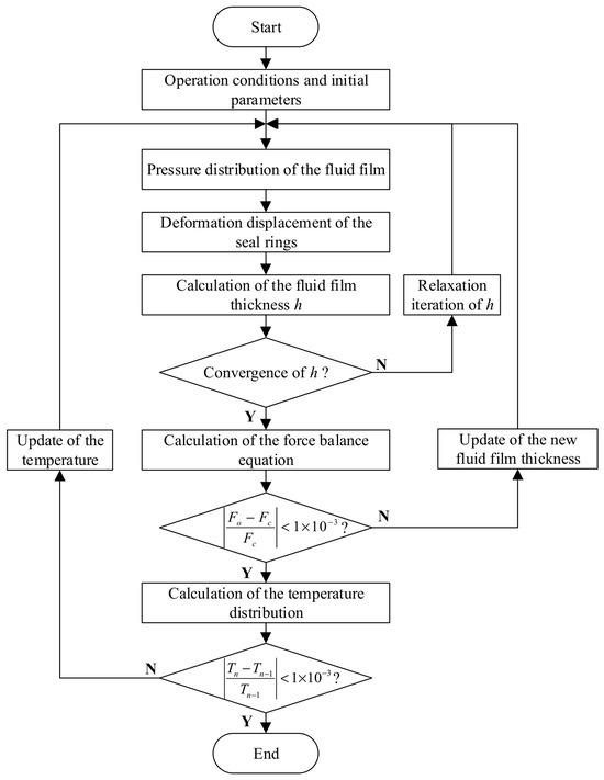
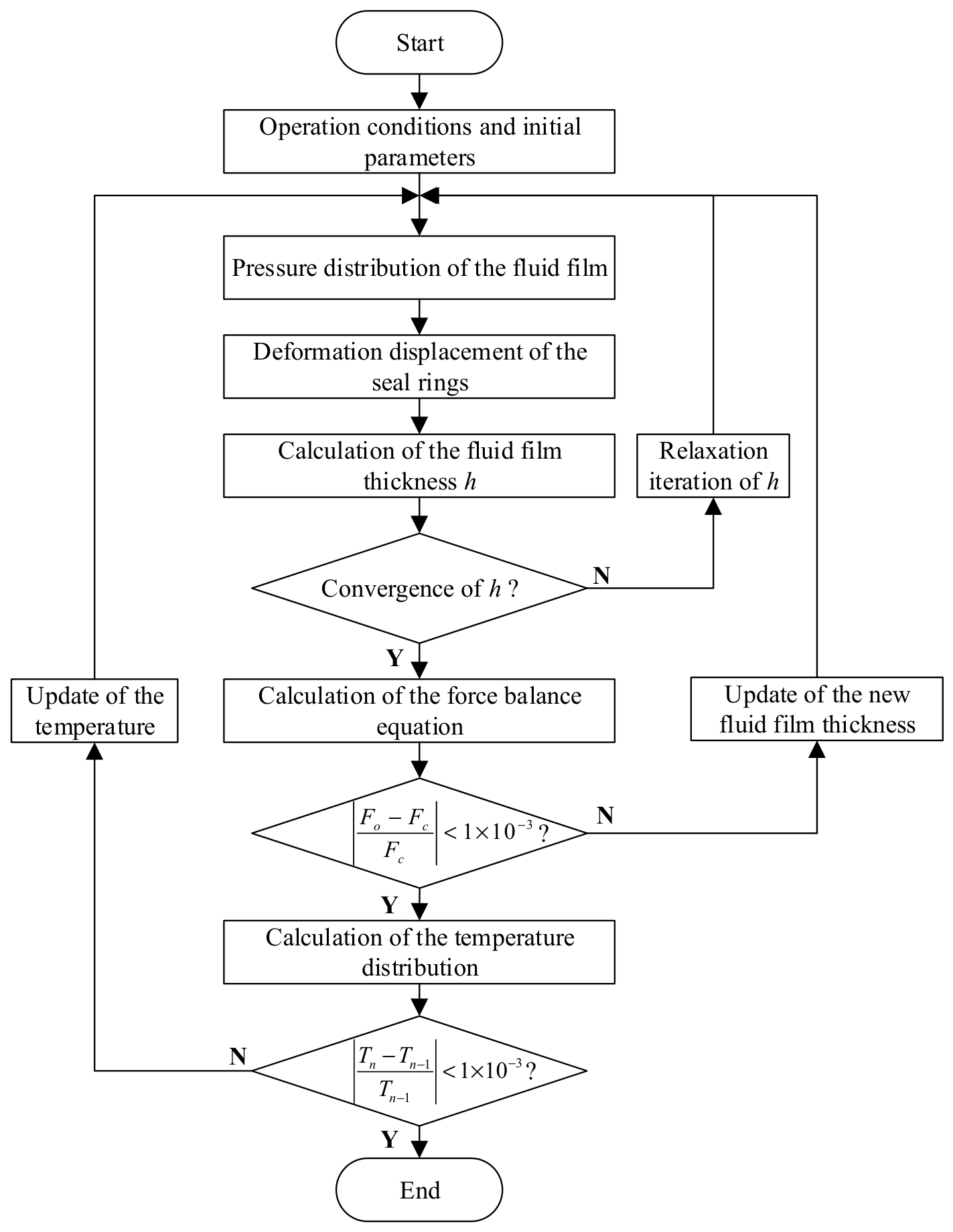
The numerical computational procedure in this study is presented in Figure 3. The solution process consists of three numerical loops. It sequentially solves the Reynolds equation, the heat conduction equations, and the deformation equations for the seal rings. The calculation will be terminated when the pressure, deformation, and temperature satisfy the coupling convergence criteria.
Figure 3.
Numerical computational procedure.
The first loop is used for the coupling between the fluid film pressure and the deformation of the seal rings. In this loop, the initial pressure distribution of the fluid film is first computed, and this pressure is then substituted into the deformation equations of the seal rings to calculate the deformation displacement of the seal rings, and the thickness of the fluid film is updated with the deformation of the seal face. Since the distribution of the fluid film thickness gives rise to variations in film pressure, the updated fluid film thickness must be fed back into the Reynolds equation to recalculate the fluid film pressure, and the new fluid film pressure is obtained from the Reynolds equation. This process is iterated until the thickness values of the fluid film from two successive iterations satisfy the convergence criterion. The convergence condition for the fluid film thickness is set as 1 × 10⁻³.
The second loop is used for the force balance, thereby determining the seal clearance hm. In this loop, the base thickness of the fluid film is updated via the force balance equation and subsequently reintroduced into the Reynolds equation. This iteration proceeds until the difference between the opening force and the closing force from two successive iterations meets the convergence requirement. Then it returns to the fluid film thickness in the first loop based on Equation (14). The convergence criterion for force balance is also defined as 1 × 10⁻³.
The third loop is dedicated to updating the temperature distribution of the fluid film. Based on the fluid film thickness obtained from the preceding calculations, the temperature distribution of the seal rings is determined. This temperature distribution is then used as a thermal load to compute the thermal deformation and to update the fluid viscosity. The Reynolds equation and the deformation equation are subsequently solved again. The temperatures of the rotor and stator are achieved by iteratively updating the relationship between fluid film viscosity and temperature until the temperatures reach a steady state [19]. That is, this process is iterated until the temperature values from two successive iterations satisfy the convergence criterion. The results are used to calculate the thermal deformation of the seal rings in the first loop.
When the three loops all satisfy the corresponding requirements of the convergence criteria, the whole calculation is finished, and the leakage rate Q and the axial stiffness of the fluid film kz can be obtained by the following formulas:
where l denotes the circumferential lines at the inner and outer radii of the seal face.
2.4. Model Verification
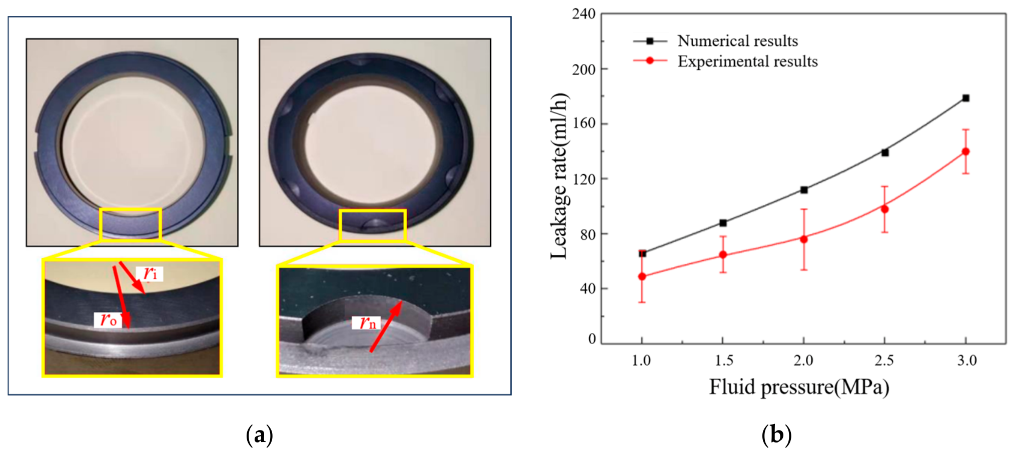
To validate the numerical model, the actual deep-grooved mechanical seal used in the literature [20] is adopted. The model in the literature [20] has the same groove profile as the present deep-grooved mechanical seal on the seal face in this study. Based on this deep-grooved structure [20] and the operating conditions (rotational speed is 2500 rpm and fluid pressure ranges from 1 MPa to 3 MPa) of the actual mechanical seal, the comparison of sealing performance is performed between the numerical simulation and experiment.
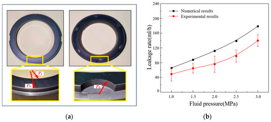
The corresponding physical image of the actual deep-grooved seal ring in the experiment is shown in Figure 4. The end face of the rotor is flat, and the grooves are manufactured on the end face of the stator. Figure 4b presents the comparison results of the leakage rate between numerical and experimental results [20]. It can be seen that the leakage rate increases with the increase in the fluid pressure. Consistent trends occur between the numerical and experimental results, which verify the feasibility and validity of the numerical model. The reason why there are data errors can be primarily attributed to the following factors: surface roughness effects not fully captured in the smooth surface model and misalignment of the seal rings during the experimental assembly process. These geometric deviations can significantly alter the local film thickness and pressure distribution, leading to fluctuations in the experimental leakage rate. In addition, variations in the environmental temperature were neglected in the numerical simulation. Changes in ambient temperature may also introduce instability in the properties and thermal deformation. Given that the clearance of the seal face is on the micron scale, it is highly sensitive to significant variations under the influence of external factors, leading to differences between the numerical and the experimental results. Despite these quantitative differences, both the numerical and experimental results exhibit a consistent increasing trend, validating the feasibility of the proposed numerical model, which can be used for predicting sealing performance, including the general flow, thermal, and mechanical behavior of textured/grooved mechanical seals under operating conditions.
Figure 4.
The verification of the actual deep-grooved seal rings: (a) Rotor and Stator; (b) Experimental results.
2.5. Mesh Independence
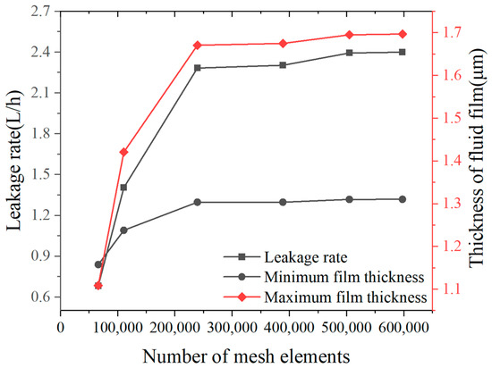
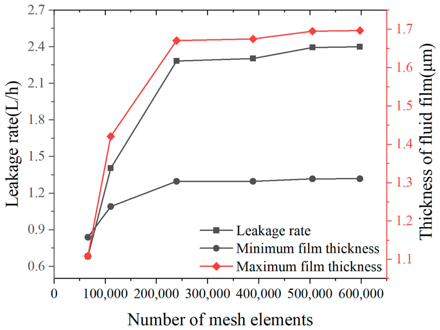
To eliminate the influence of mesh on the computational results, a mesh independence study was conducted under a fluid pressure of 15 MPa, a spring specific pressure of 0.27 MPa, and a rotational speed of 2000 rpm at different numbers of mesh elements. To ensure computational accuracy, the meshes near the end faces of the seal rings are denser than those far away from the faces. The results of the numerical simulation are presented in Figure 5. It can be observed that the calculated results of leakage rate, minimum film thickness, and maximum film thickness all converge to stable values as the number of mesh elements increases. Considering both the computational accuracy and computational cost, an appropriate mesh with 239,329 elements, including 236,159 tetrahedral elements and 3170 triangular elements, was adopted in this study.
Figure 5.
The influence of the number of mesh elements on sealing performance.
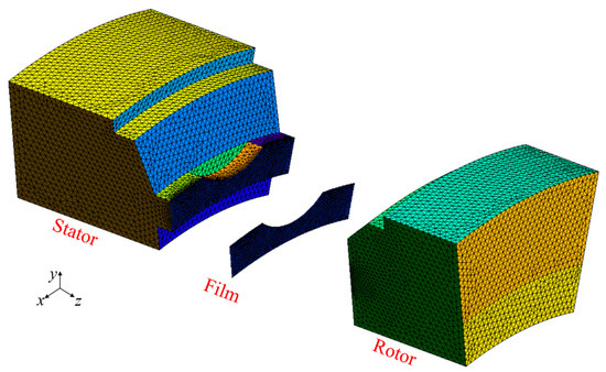
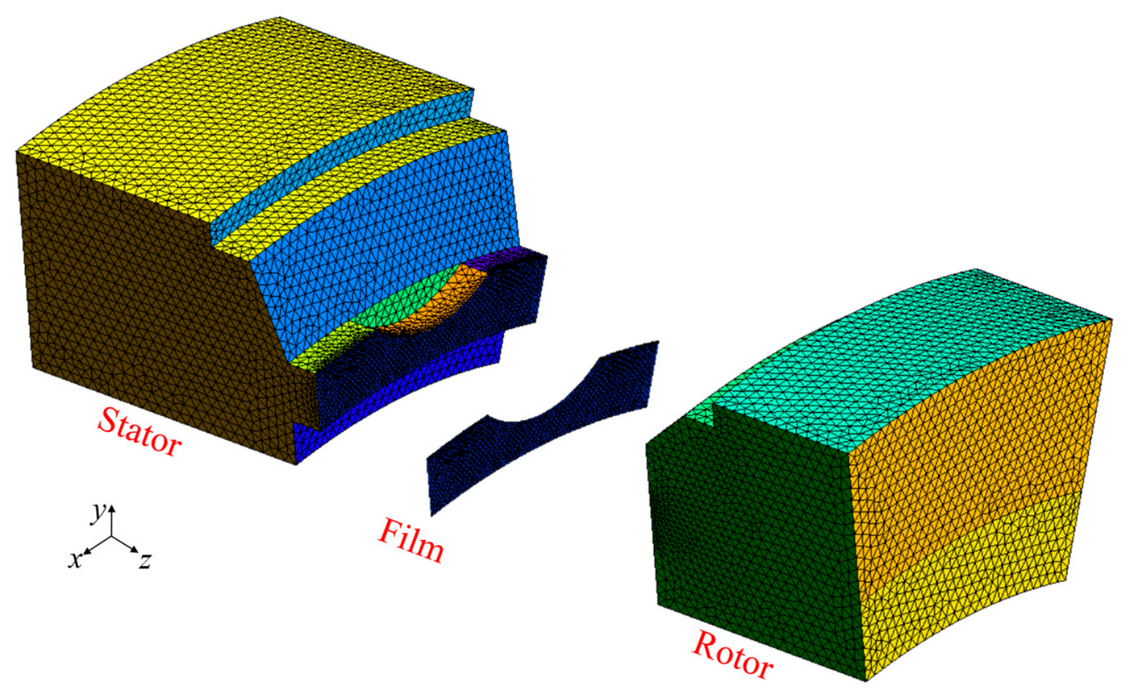
The grid distributions of the periodic seal rings and fluid film are presented in Figure 6 in this study. The total number of elements of the rotor, stator, and fluid film is about 122,464, 113,695, and 3170, respectively.
Figure 6.
The finite element model of seal rings.
3. Results and Discussion
3.1. TEHD Mechanism
To analyze the TEHD mechanism of the mechanical seal, the above-mentioned numerical procedure is conducted on the deep-grooved mechanical seal under the conditions of p = 15 MPa and n = 2000 rpm in the study.
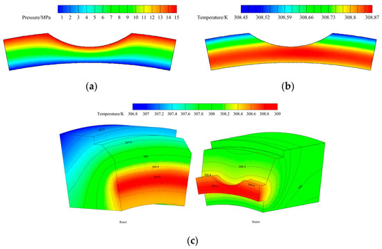
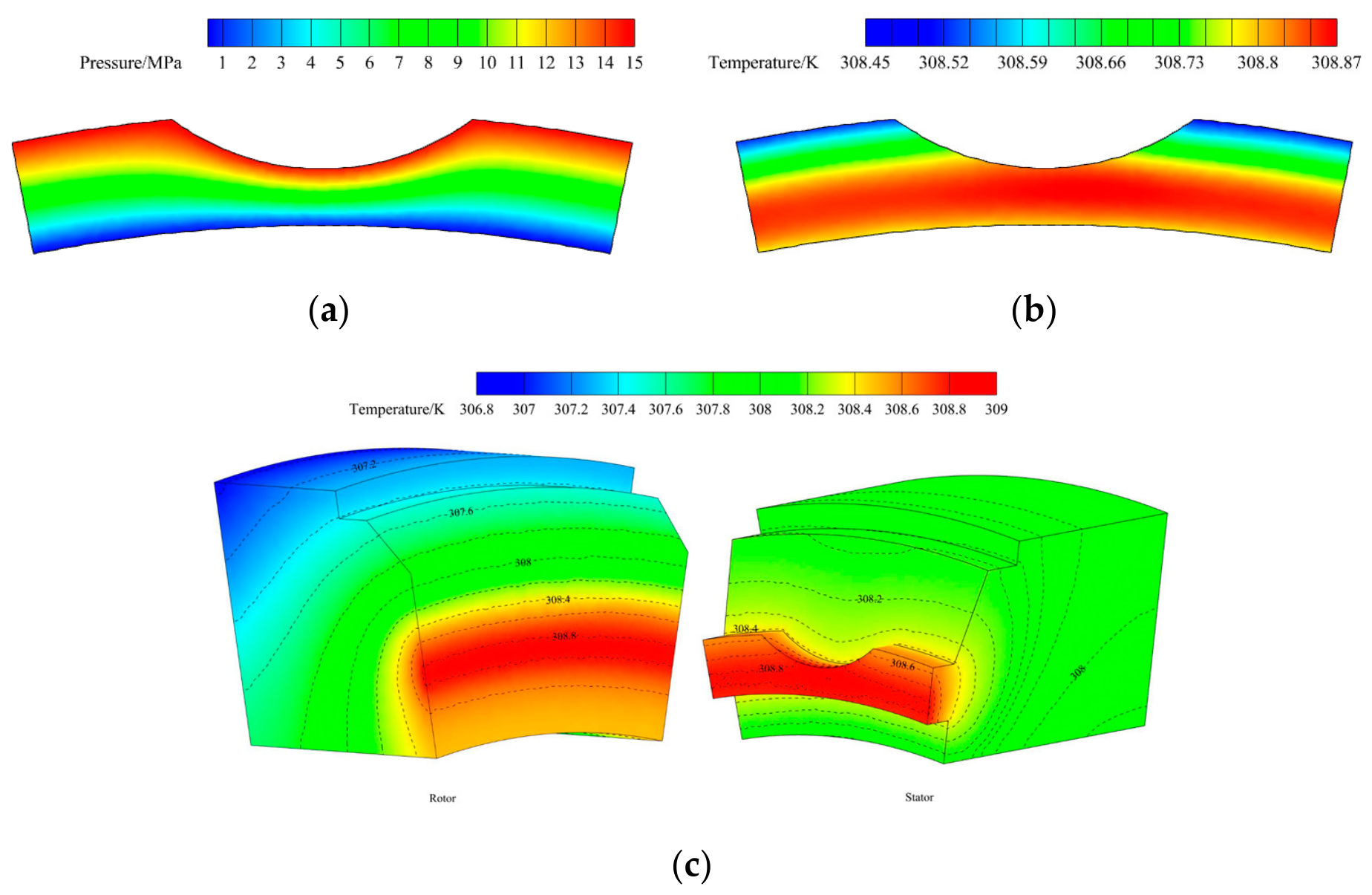
Figure 7 presents the contour graph of the pressure and temperature distribution of the fluid film under the conditions of po = 15 MPa and n = 2000 rpm. From Figure 7a, it can be observed that no cavitation occurs in the fluid film under the present condition. The pressure of the fluid film decreases gradually from the outer side to the inner side. The maximum pressure of the fluid film is 15 MPa, indicating that no significant hydrodynamic effect is generated in the fluid film. The pressure distribution is closely dependent on the distribution of the fluid film thickness presented in Figure 8a.
Figure 7.
The pressure and temperature distribution of the fluid film and seal rings: (a) Pressure of fluid film; (b) Temperature of fluid film; (c) Temperature of seal rings.
Figure 8.
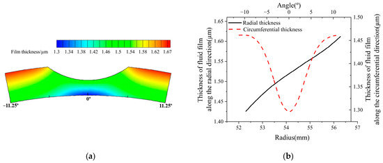
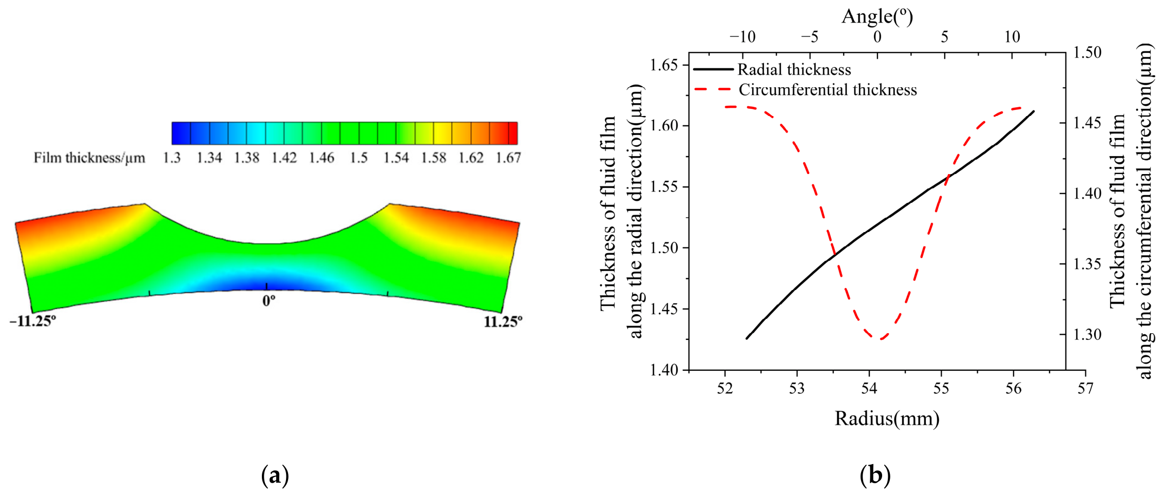
The distribution of the fluid film thickness: (a) Contour graph; (b) Thickness distribution.
The temperature distribution on the seal face is consistent with that of the fluid film. The temperature of the fluid film exhibits a gradual increase from the outer side to the inner side, and it reaches a maximum value at the middle-diameter position near the inner side of the seal face, as shown in Figure 7b,c. This is because the outer side serves as the convective heat transfer boundary with the fluid medium, while the inner side performs convective heat transfer with the atmosphere. Greater convection occurs at the outer side of the seal face. Meanwhile, the heat generated by fluid leakage also increases the fluid film temperature near the groove region, resulting in an increase in the fluid film temperature. The maximum temperature on the seal face is approximately 308.8 K, while the temperature difference between the inner and outer sides is relatively small. The temperature differences across the seal face result in thermal deformation of the seal face. Due to the rotational action of the rotor, the temperature distribution along the circumferential direction is relatively uniform, resulting in minimal circumferential variation in the thermal deformation of the seal face.
The distribution of the fluid film thickness under the corresponding conditions of po = 15 MPa and n = 2000 rpm is shown in Figure 8. The fluid film profile is caused by the deformation of the seal face. From Figure 8a, it can be seen that the maximum film thickness of about 1.67 μm appears at the outer side of the sealing gap, corresponding to the high-pressure region of the fluid film. The minimum thickness of the fluid film is about 1.3 μm and occurs at the inner side, which indicates that the hydrostatic effect of the fluid film makes the seal face of the mechanical seal operate in a non-contacting state. It can be concluded that the mechanical seal operates in the state of full-film lubrication under the current condition [21]. The fluid film thickness gradually decreases from the outer side to the inner side, indicating that there is an obvious taper along the leakage direction, and a convergent sealing gap is generated.
Figure 8b presents the distribution of the fluid film thickness at a radius of 52.3 mm and at an angle of 5.625° for the description of the circumferential and radial results, respectively. The fluid film thickness along the radial direction decreases from the outer side to the inner side, and the thickness difference is about 0.19 µm at the angle of 5.625°. The fluid film thickness along the circumferential direction has a waviness with an amplitude of about 0.165 µm at a radius of 52.3 mm. This phenomenon indicates that a hydrodynamic effect is generated, although the amplitude of the circumferential waviness is small, facilitating the generation of a thermo-hydrodynamic wedge effect. Consequently, it is concluded that the load-carrying capacity of the fluid film in the deep-grooved face seal predominantly relies on the hydrostatic effect, and there is a relatively minor contribution from the hydrodynamic effect, which is consistent with the results in Reference [11].
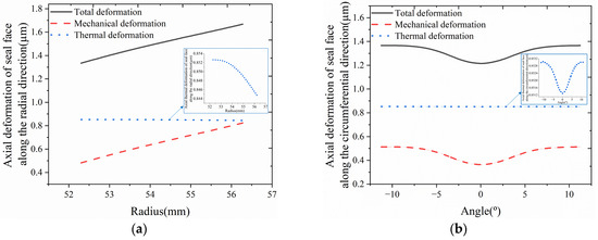
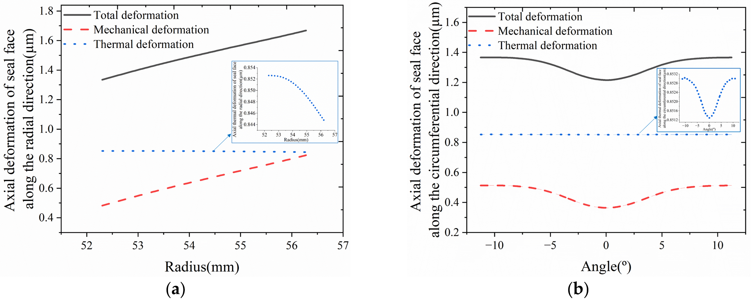
Figure 9 presents the total axial deformation distribution of the seal face under the conditions of po = 15 MPa and n = 2000 rpm, including the axial mechanical and axial thermal deformation. Here, the results at a radius of 52.3 mm and at an angle of 5.625° are also presented for the description of the circumferential and radial results.
Figure 9.
The axial deformation of the seal face: (a) Radial direction; (b) Circumferential direction.
In the total axial deformation of the seal face, the axial thermal deformation is predominant compared to the axial mechanical deformation. In Figure 9a, it is apparent that the axial mechanical deformation of the seal face decreases from the outer side to the inner side of the seal face along the radial direction, with a deformation difference of approximately 0.342 μm between the inner and outer sides. In contrast, the axial thermal deformation of the seal face decreases from the inner side to the outer side along the radial direction due to the higher temperature near the inner side, although the temperature difference across the seal face is relatively small. The maximum magnitude of the axial thermal deformation along the radial direction is approximately 0.85 μm, and the difference in the axial thermal deformation along the radial direction between the maximum and minimum values is only about 0.008 μm. This indicates that the variation in the axial thermal deformation along the radial direction is very small. Therefore, it can be concluded that the axial thermal deformation along the radial direction remains nearly uniform due to the small temperature difference, as shown in Figure 7c, despite being larger than the axial mechanical deformation, with a maximum of approximately 0.82 μm at the outer side.
Since the variation trend of the axial thermal deformation is opposite to that of the axial mechanical deformation along the radial direction, the axial thermal deformation partially counteracts the radial taper induced by the axial mechanical deformation. Under the combined effect of both deformations, the total axial deformation of the seal face along the radial direction exhibits a gradually decreasing trend from the outer side to the inner side of the seal face, which results in a convergent fluid film profile. The difference in the total axial deformation of the seal face along the radial direction between the inner and outer sides is about 0.334 μm.
Figure 9b presents the axial deformation of the seal face along the circumferential direction. Both the axial mechanical and thermal deformations exhibit waviness variations along the circumferential direction, and they have a consistent variation trend along the circumferential direction. Accordingly, the circumferential waviness amplitude of the total axial deformation, with a magnitude of approximately 0.15 μm, is the result of the direct superposition of both deformations.
Although the axial thermal deformation along the circumferential direction is relatively larger than that of the axial mechanical deformation, the circumferential waviness amplitude of the axial thermal deformation is approximately 0.0018 μm, which is significantly smaller than that of the axial mechanical deformation with a magnitude of approximately 0.149 μm. No significant variation in the circumferential waviness for the axial thermal deformation occurs due to the relatively uniform temperature distribution along the circumferential direction shown in Figure 7c, and there is minimal impact on the thermo-hydrodynamic wedge effect. This differs from Mayer et al.’s conclusion that deep grooves produce strong cooling effects and generate significant circumferential waviness [22,23]. Unlike the axial thermal deformation, the axial mechanical deformation of the seal face varies significantly along the circumferential direction, and the amplitude of circumferential waviness caused by the axial mechanical deformation is about 0.149 μm. This indicates that the thermo-hydrodynamic wedge effect of the seal face is primarily dominated by the mechanical deformation, while the thermal deformation plays a relatively minor role despite its larger magnitude. This is because the axial thermal deformation of the seal face is relatively uniform without generating significant gradients along the radial and circumferential directions, due to the small temperature gradient across the seal face shown in Figure 7c. In contrast, the axial mechanical deformation varies significantly and produces significant spatial gradients in both the radial and circumferential directions due to the non-uniform pressure distribution acting on the seal face, despite being smaller in magnitude compared with thermal deformation.
Compared to the total axial deformation of the seal face along the circumferential direction, the total axial deformation of the seal face along the radial direction exhibits a relatively larger magnitude. Consequently, the resulting hydrostatic effect is crucial for ensuring the stable operation of the mechanical seal.
In the present study, due to the relatively uniform temperature distribution of the seal face along the radial and circumferential directions shown in Figure 7c, the radial taper and circumferential waviness effect induced by the thermal deformation is minimal. This implies that the cooling effect from the deep grooves has a non-significant influence on radial taper and circumferential waviness, and the thermal effect plays a relatively minor role in the thermo-hydrodynamic wedge effect. It is worth noting that in the work of Mayer et al. [22,23], the deep-grooved mechanical seal operates with a small film thickness of approximately 0.2~1 μm [22]. Under this thin-film lubrication condition, substantial viscous shear heat is generated, potentially accompanied by contact-induced heating, resulting in a pronounced temperature rise in the seal ring. Furthermore, their research primarily focuses on seal rings with relatively smaller diameters (<100 mm), and notable differences exist in the groove location on the seal ring, width of seal face, material, number of grooves, and groove dimensions compared to the present study. In addition, the rotational speed in our study is within the range of 2500 rpm, whereas Mayer et al.’s work operated under high-speed conditions larger than 3000 rpm. These discrepancies in operating conditions, geometric configurations, and material parameters account for the differences observed between the conclusions of the two studies.
3.2. Deformation Characteristics at Different Fluid Pressures
To further investigate the deformation characteristics and the sealing performance of the mechanical seal, the influence of the operating conditions is focused on in the research. The numerical calculation is conducted on the deep-grooved mechanical seal under the conditions of psp = 0.27 MPa and n = 2000 rpm in the study. Here, the characteristics at the radius of 52.3 mm and at the angle of 5.625° are also presented for the description of the circumferential and radial results, respectively.
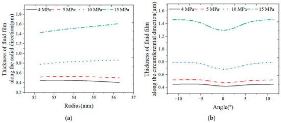
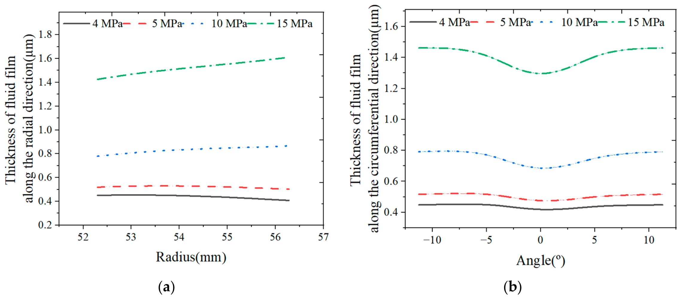
The distribution of the fluid film thickness under different fluid pressures is described in Figure 10. Due to the increased pressure difference causing greater mechanical deformation, the fluid film thickness along the radial direction and the radial taper of the fluid film gradually increase, and the location of the maximum thickness along the radial direction gradually shifts toward the outer side, as shown in Figure 10a. When the pressure is larger than 5 MPa, the maximum thickness of the fluid film along the radial direction occurs at the outer side; otherwise, it occurs at the inner side. The thickness difference at the inner and outer sides along the radial direction reaches its maximum value at a pressure of 15 MPa, and it is about 0.19 μm.
Figure 10.
The distribution of the fluid film thickness at different fluid pressures: (a) Radial direction; (b) Circumferential direction.
From Figure 10b, it can be seen that a similar variation trend occurs for the fluid film thickness along the circumferential direction at different fluid pressures. The circumferential thickness of the fluid film also increases with an increase in the fluid pressure, and the amplitude of the circumferential waviness also gradually grows from about 0.034 μm to 0.165 μm, indicating that the thermo-hydrodynamic wedge effect of the seal face becomes more pronounced as pressure increases. Thus, it can be concluded that an increase in the fluid pressure enhances the hydrostatic effect of the fluid film.
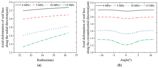
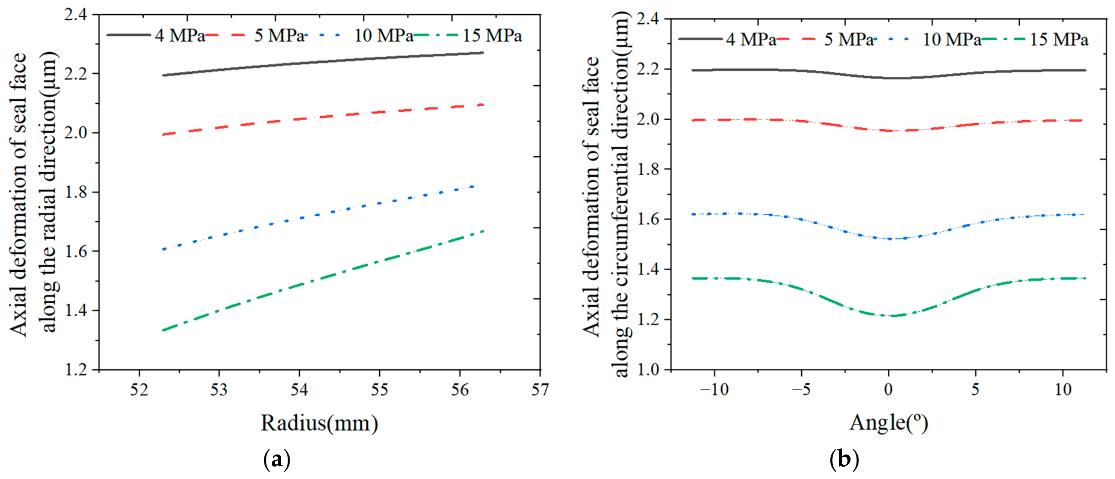
The total axial deformation characteristics of the seal face under different fluid pressures are described in Figure 11.
Figure 11.
The total axial deformation characteristics of the seal face at different fluid pressures: (a) Radial direction; (b) Circumferential direction.
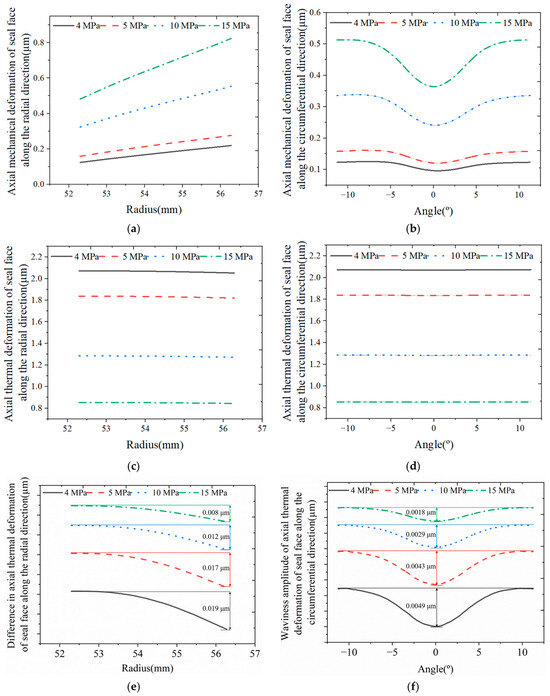
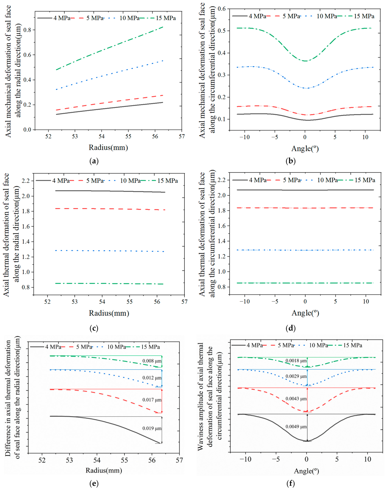
A similar trend also occurs for the deformation of the seal face at different fluid pressures. As shown in Figure 11a, the maximum total axial deformation displacement along the radial direction can be obtained at the outer side, and the minimum total axial deformation occurs at the inner side at different fluid pressures. Due to the increased fluid film thickness leading to a reduced temperature rise, the axial thermal deformation of the seal face along both the radial and circumferential directions exhibits a decreasing trend with increasing fluid pressure, and it presents a relatively uniform distribution along the radial and circumferential directions due to the small temperature gradient across the seal face, as shown in Figure 12c,d.
Figure 12.
The axial mechanical and thermal deformation characteristics of the seal face at different fluid pressures: (a) Axial mechanical deformation along the radial direction; (b) Axial mechanical deformation along the circumferential direction; (c) Axial thermal deformation along the radial direction; (d) Axial thermal deformation along the circumferential direction; (e) Displacement difference in the axial thermal deformation along the radial direction; (f) Waviness amplitude of the axial thermal deformation along the circumferential direction.
Furthermore, with axial thermal deformation being dominant on the seal face, it is apparent from Figure 11 that the total axial deformation of the seal face along the radial and circumferential directions decreases gradually with the increase in fluid pressure, while the radial taper and the amplitude of the circumferential waviness gradually increase, reaching approximately 0.334 μm in axial deformation difference along the radial direction between the inner and outer side of the seal face and 0.15 μm in amplitude of the circumferential waviness in the given range, which is primarily induced by the larger displacement gradient in axial mechanical deformation along both the radial and circumferential directions for increased fluid pressure, as presented in Figure 12a,b. At different fluid pressures, the axial mechanical deformation along the radial direction increases from the inner side to the outer side. In the given range, the maximum axial mechanical deformation of about 0.82 μm is obtained at the outer side at a pressure of 15 MPa, and the difference in axial mechanical deformation along the radial direction between the inner and outer sides of the seal face increases from approximately 0.1 μm to 0.342 μm. Meanwhile, the amplitude of the circumferential waviness in the axial mechanical deformation increases as the fluid pressure increases, reaching approximately 0.149 μm at a pressure of 15 MPa.
In contrast, the axial thermal deformation presents a relatively uniform distribution along both the radial and circumferential directions due to the small temperature gradient across the seal face, as shown in Figure 12c,d. The difference between the maximum and minimum values along the radial direction decreases from 0.019 μm to 0.008 μm, and the amplitude of the circumferential waviness decreases from 0.0049 μm to 0.0018 μm in the given range, as presented in Figure 12e,f, respectively. The axial mechanical deformation of the seal face governs the circumferential waviness of the film profile. The thermo-mechanical coupling deformation of the seal face results in a convergent taper between the inner and outer sides of the seal face.
Therefore, based on the above analysis, it can be confirmed that the hydrodynamic effect of the fluid film originates primarily from the axial mechanical deformation of the seal face and becomes progressively weaker as the fluid pressure increases due to the dominant hydrostatic effect.
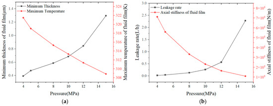
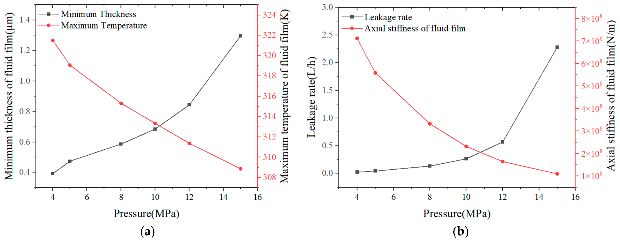
Figure 13 presents the sealing performance of the mechanical seal at different fluid pressures, where the axial stiffness, maximum temperature, minimum thickness of the fluid film, and the leakage rate are mainly focused on. As the fluid pressure increases, the fluid film thickness increases, which results in a decrease in the maximum temperature and the axial stiffness of the fluid film, and consequently an increase in the leakage rate. The leakage rate is about 0.023 L/h, and the axial stiffness of the fluid film is about 7.12 × 10⁸ N/m at a pressure of 4 MPa. The reason why the axial stiffness of the fluid film is reduced is that a large film thickness is detrimental to maintaining sealing stability. Due to the balance between the opening force and closing force of the fluid film, the increased radial taper shown in Figure 9 results in an increase in the minimum thickness of the fluid film.
Figure 13.
The sealing performance of the mechanical seal at different fluid pressures: (a) Minimum thickness and maximum temperature; (b) Leakage rate and axial stiffness of fluid film.
To further evaluate the influence of fluid pressures on the sealing performance of the present deep-grooved mechanical seal, a local sensitivity analysis is conducted based on the dimensionless relative sensitivity coefficient. The local sensitivity coefficient Si is defined as follows:
where the subscript i represents a specific index or identifier; Y denotes the value of the sealing performance parameter, such as leakage rate or film thickness, at operating condition; Yo is the reference value of the sealing performance parameter; Xi represents the i-th operating parameter, for example, fluid pressure or rotational speed; and Xi,o denotes the corresponding reference value of the i-th operating parameter.
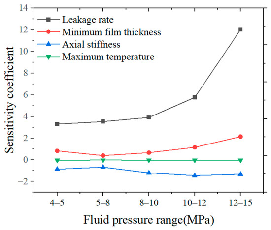
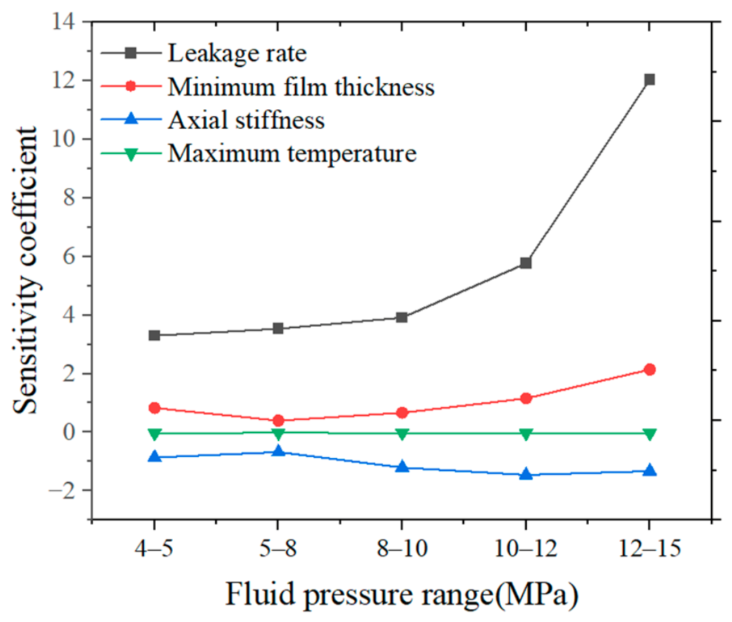
The sensitivity coefficients of the leakage rate, minimum film thickness, axial stiffness, and maximum temperature of the fluid film under different fluid pressure conditions are illustrated in Figure 14. It can be seen that the sensitivity coefficient of the leakage rate with respect to fluid pressure exhibits a pronounced increasing trend, ranging from approximately 3.30 to 12.04, indicating that the leakage rate becomes increasingly sensitive to fluid pressure variations at higher pressure levels. Similarly, the sensitivity coefficient of the minimum film thickness with respect to fluid pressure also presents an upward trend in the relatively high-pressure region (larger than 5 MPa), increasing from approximately 0.40 to 2.14. However, in the relatively low-pressure region (below 5 MPa), its sensitivity coefficient is about 0.83, demonstrating a higher sensitivity to fluid pressure variations compared to the initial stage of the high-pressure region. Conversely, the sensitivity coefficients of both the axial stiffness and maximum temperature of the fluid film are negative, indicating that an increase in fluid pressure leads to a reduction in both the axial stiffness and temperature of the fluid film. The maximum sensitivity coefficient of the axial stiffness reaches about −1.46 within the given pressure range. Specifically, a 1% increase in fluid pressure results in approximately a 1.46% reduction in axial stiffness. In contrast, the maximum temperature exhibits low sensitivity to fluid pressure variations, with sensitivity coefficients of about −0.03 below 5 MPa and −0.032 above 5 MPa. In summary, fluid pressure exerts a significant influence on the leakage rate, especially under high-pressure conditions, whereas its impact on the maximum temperature of the fluid film remains marginal.
Figure 14.
The sensitivity coefficients of the performance parameters under different fluid pressures.
3.3. Deformation Characteristics at Different Spring Forces
The numerical calculations on the deformation characteristics at different spring forces are conducted on the deep-grooved mechanical seal under the conditions of po = 15 MPa and n = 2000 rpm in the study. The spring force, in the form of the spring specific pressure, ranges from 0.23 MPa to 0.29 MPa in this part. Here, the characteristics at the radius of 52.3 mm and at the angle of 5.625° are also presented for the description of the circumferential and radial results, respectively.
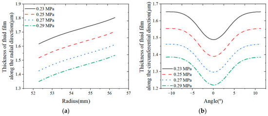
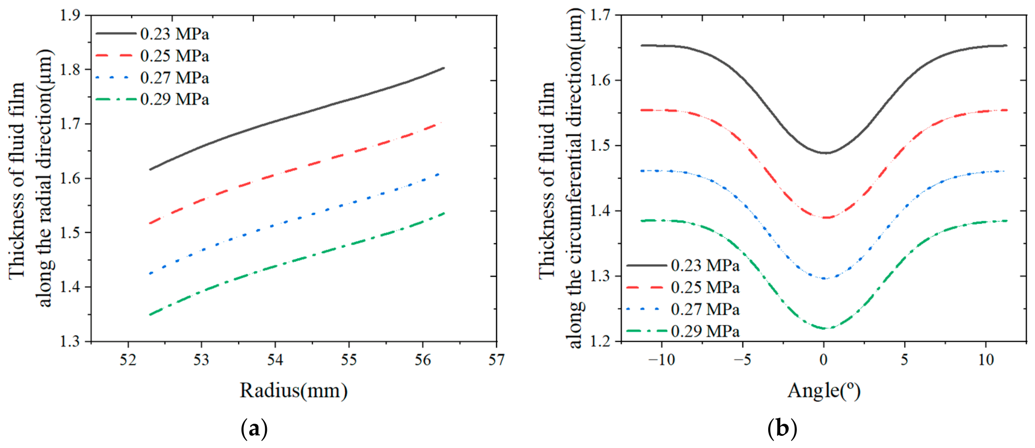
Figure 15 presents the distribution of the fluid film thickness under different spring specific pressures.
Figure 15.
The distribution of the fluid film thickness at different spring specific pressures: (a) Radial direction; (b) Circumferential direction.
With the increase in the spring specific pressure, the radial and circumferential thickness of the fluid film both decrease. The maximum radial thickness of the fluid film is also obtained on the outer side. However, there is no significant variation in the radial taper and circumferential waviness of the fluid film as the spring specific pressure increases, with the amplitude of the waviness remaining about 0.17 μm, as shown in Figure 15b. This indicates that the thermo-hydrodynamic wedge effect of the seal face is not enhanced as the spring specific pressure increases.
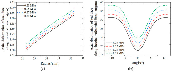
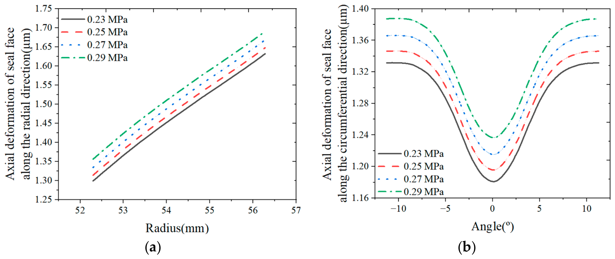
The deformation characteristics of the seal face under different spring specific pressures are described in Figure 16. A similar trend is also observed for the total axial deformation of the seal face at different spring specific pressures. As shown in Figure 16a, the maximum deformation along the radial direction can be obtained at the outer side, and it can reach up to 1.69 μm at the spring pressure of 0.29 MPa. The minimum deformation along the radial direction is generated at the inner side, and the minimum value is about 1.3 μm at the spring pressure of 0.23 MPa. Due to the reduced fluid film thickness leading to an increased temperature rise, the axial deformation of the seal face along the radial and circumferential directions increases gradually with the increase in spring specific pressure, while no significant variation occurs in the radial taper and circumferential waviness shown in Figure 16b. It can be concluded that there is little difference in the thermo-hydrodynamic wedge effect at different spring specific pressures.
Figure 16.
The total axial deformation characteristics of the seal face at different spring specific pressures: (a) Radial direction; (b) Circumferential direction.
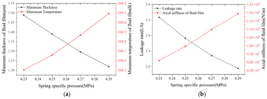
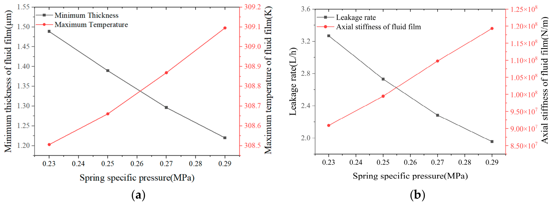
Figure 17 presents the sealing performance of the mechanical seal at different spring specific pressures. Due to the reduced thickness of the fluid film caused by the increased spring specific pressure, the leakage rate and minimum thickness of the fluid film decrease, and the maximum temperature and axial stiffness of the fluid film are enhanced. At a spring specific pressure of 0.29 MPa, although the minimum thickness of the fluid film is about 1.22 μm, the axial stiffness of the fluid film is about 1.19 × 10⁸ N/m, and the leakage rate is smaller than 2.0 L/h. That is why a smaller fluid film thickness is beneficial for sealing stability.
Figure 17.
The sealing performance of the mechanical seal at different spring specific pressures: (a) Minimum thickness and maximum temperature; (b) Leakage rate and axial stiffness of fluid film.
To further evaluate the influence of spring specific pressure on the sealing performance of the present deep-grooved mechanical seal, a local sensitivity analysis is also performed based on the dimensionless relative sensitivity coefficient.
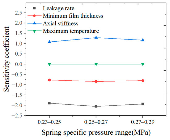
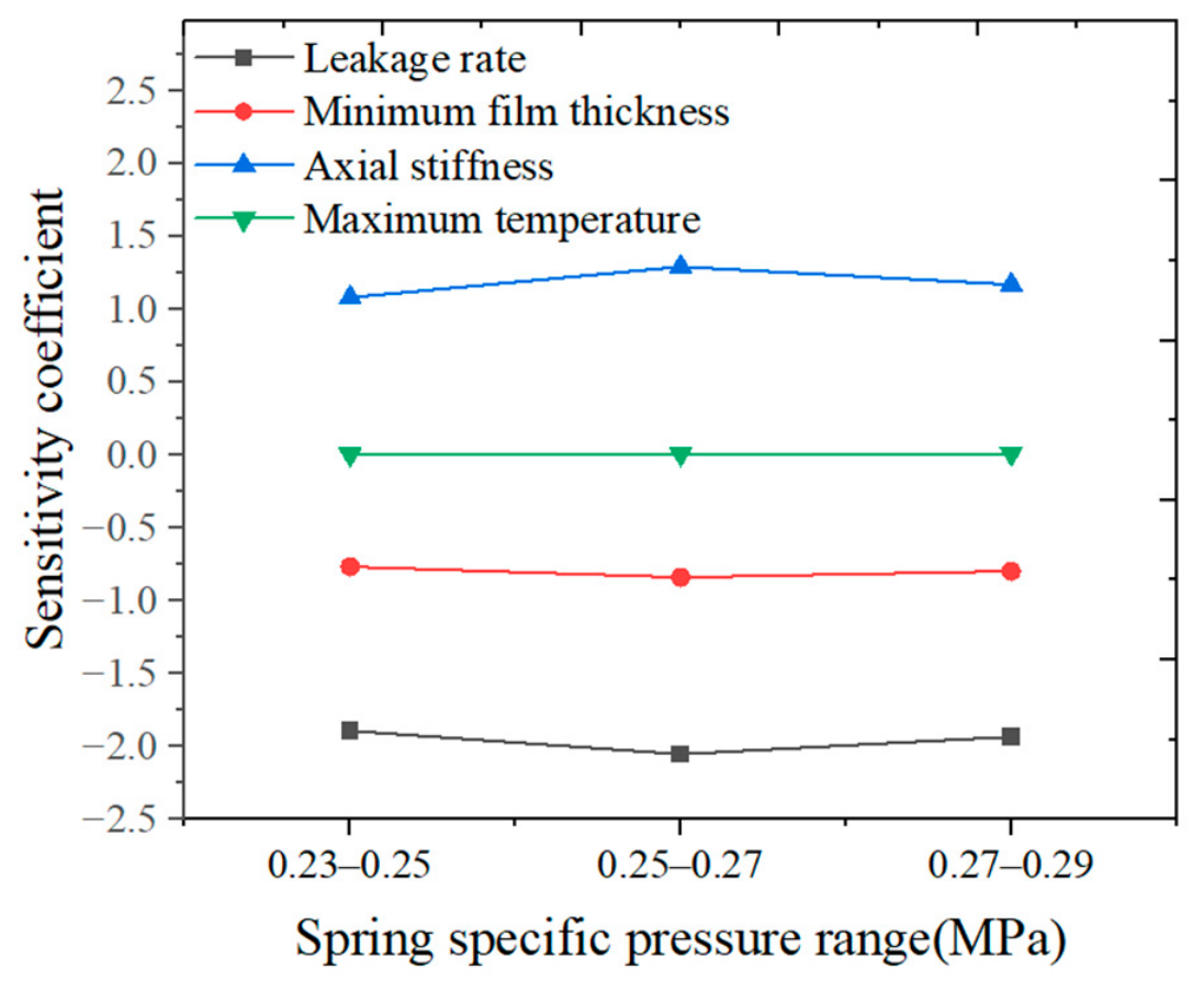
The sensitivity coefficients of the leakage rate, minimum thickness, axial stiffness, and maximum temperature of the fluid film under different spring specific pressures are described in Figure 18.
Figure 18.
The sensitivity coefficients of the performance parameters under different spring specific pressures.
As shown in Figure 18, the sensitivity coefficients of the performance parameters with respect to spring specific pressure exhibit no significant upward or downward trends, indicating a relatively stable sensitivity in the given range. Specifically, the sensitivity coefficient of the leakage rate with respect to spring specific pressure remains approximately constant at around −2.0 across all intervals (ranging from −1.89 to −2.05). This negative value also signifies an inverse relationship, implying that an increase in spring specific pressure leads to a reduction in the leakage rate. Similarly, the sensitivity coefficient of minimum film thickness with respect to spring specific pressure remains stable at approximately −0.8 across all intervals (ranging from −0.77 to −0.84). In contrast, the sensitivity coefficients of the axial stiffness and maximum temperature are positive, suggesting that increasing the spring specific pressure enhances the axial stiffness and temperature of the fluid film. The maximum sensitivity coefficient of the axial stiffness reaches approximately 1.29 within the given range. Conversely, the maximum sensitivity coefficient of the maximum temperature of the fluid film is merely 0.0099, indicating a very low sensitivity to the variation in the spring specific pressure. In summary, the influence of spring specific pressure on the performance parameters is relatively stable under the operating conditions in which the influence on the leakage rate is more significant, and the impact on the temperature of the fluid film also remains insignificant.
3.4. Deformation Characteristics at Different Rotational Speeds
The deformation characteristics at different rotational speeds are conducted on the deep-grooved mechanical seal under the conditions of po = 15 MPa and psp = 0.27 MPa, and the rotational speed is ranged from 500 rpm to 2500 rpm in this part. Here, the characteristics at the radius of 52.3 mm and at the angle of 5.625° are also presented for the description of the circumferential and radial results, respectively.
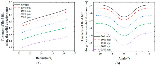
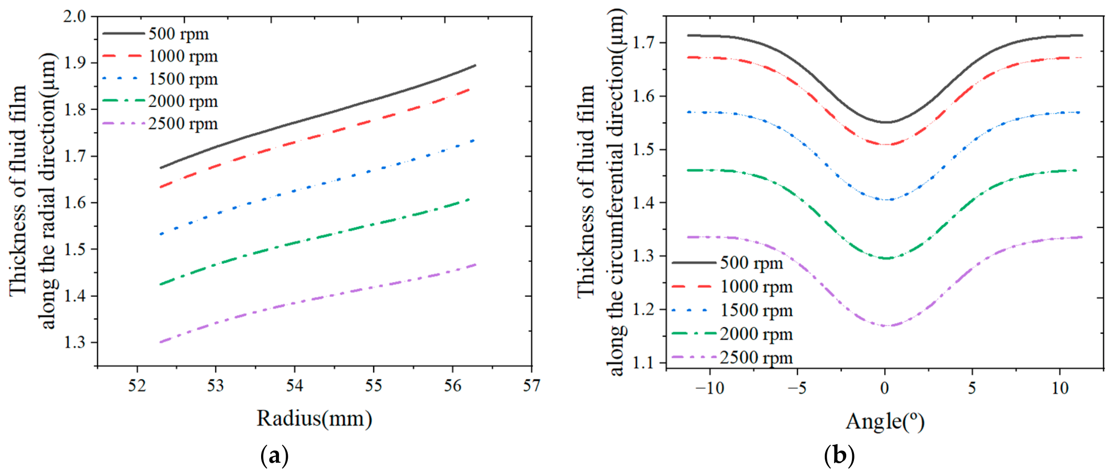
Figure 19 presents the distribution of the fluid film thickness under different rotational speeds. Due to the increased viscous shear heat, the film temperature increases, and the fluid viscosity is reduced, thereby diminishing the hydrodynamic effect. As a result, the load-carrying capacity of the fluid film decreases. The thickness of the fluid film along the radial and circumferential directions decreases as the rotational speed increases. The maximum and minimum values of the fluid film thickness along the radial direction can also be obtained at the outer and inner sides, respectively. In Figure 19, although there is no significant variation in the radial taper and circumferential waviness of the fluid film as the rotational speed increases, the radial taper presents a decreasing trend, and the amplitude of the circumferential waviness shows an increasing trend as the rotational speed increases in the given range. As shown in Figure 19a, the difference in the fluid film thickness along the radial direction between the inner and outer sides decreases from about 0.22 μm to 0.16 μm as the rotational speed increases. This is because the enhanced viscous shear heat at high speeds elevates the film temperature and induces greater thermal deformation of the seal face, which partially counteracts the convergent taper produced by the mechanical deformation, and consequently the film thickness difference along the radial direction between the inner and outer sides is decreased.
Figure 19.
The distribution of the fluid film thickness at different rotational speeds: (a) Radial direction; (b) Circumferential direction.
In addition, with increasing rotational speed, the viscous shear effect in the fluid film increases, which would generally enhance the hydrodynamic effect. However, as discussed above, the intensified shear heat reduces the viscosity and diminishes the hydrodynamic effect. As a result, the increase in the amplitude of the circumferential waviness of the film thickness is very small. As shown in Figure 19b, the amplitude of the circumferential waviness for the fluid film thickness increases from about 0.163 μm to 0.167 μm as the rotational speed increases in the given rotational speed range at a fluid pressure of 15 MPa, corresponding to an increase of approximately 2.5%. This small variation further confirms that the hydrodynamic effect is limited under the studied conditions. The load-carrying capacity of the fluid film predominantly relies on the hydrostatic effect.
Figure 20 presents the total axial deformation characteristics of the seal face under different rotational speeds.
Figure 20.
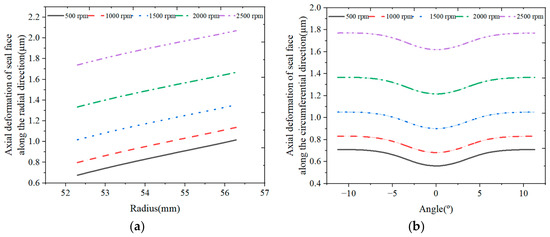
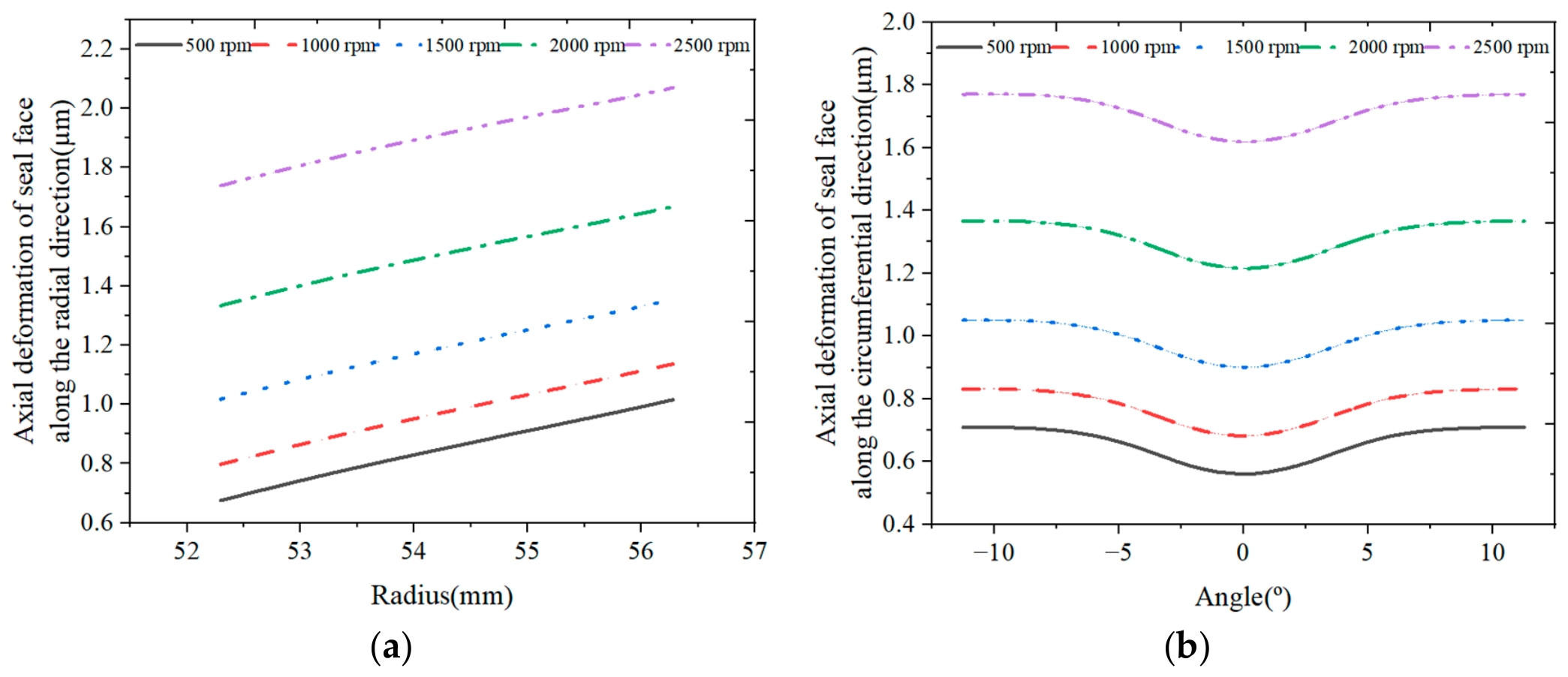
The total axial deformation characteristics of the seal face at different rotational speeds: (a) Radial direction; (b) Circumferential direction.
The total axial deformation of the seal face along the radial and circumferential directions increases as the rotational speed increases, while there are marginal variations in the radial taper and circumferential waviness of the total axial deformation of the seal face. Specifically, as shown in Figure 20a, the difference in the total axial deformation of the seal face along the radial direction between the inner and outer sides decreases from approximately 0.339 μm to 0.330 μm, because the axial thermal deformation partially offsets the radial taper induced by the axial mechanical deformation. Concurrently, the amplitude in the circumferential waviness of the total axial deformation increases from approximately 0.148 μm to 0.152 μm in Figure 20b due to the enhanced hydrodynamic effect as the rotational speed increases. This minor change indicates that the thermo-hydrodynamic wedge effect of the seal face is not significantly enhanced as the rotational speed increases.
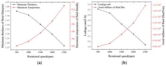
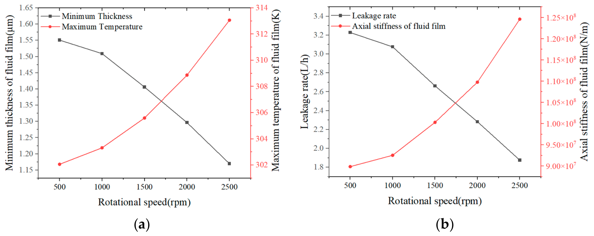
Figure 21 presents the sealing performance of the mechanical seal at different rotational speeds. As mentioned above, the load-carrying capacity decreases with increasing rotational speed. Accordingly, the minimum thickness of the fluid film also decreases as the rotational speed increases, and the minimum thickness of the fluid film is about 1.17 μm at a rotational speed of 2500 rpm in the given range. Consequently, the reduced thickness of the fluid film results in a decreased leakage rate and an increased axial stiffness of the fluid film with increasing rotational speed. The minimum leakage rate of about 1.88 L/h is obtained at a rotational speed of 2500 rpm in the given range.
Figure 21.
The sealing performance of the mechanical seal at different rotational speeds: (a) Minimum thickness and maximum temperature; (b) Leakage rate and axial stiffness of fluid film.
The maximum temperature and axial stiffness of the fluid film are enhanced with increasing rotational speed, caused by the reduced fluid film thickness. The maximum axial stiffness of the fluid film of about 1.25 × 10⁸ N/m is obtained at a rotational speed of 2500 rpm in the given range. The larger the maximum temperature of the fluid film, the greater the axial thermal deformation of the seal face. However, the axial thermal deformation has little effect on the radial taper and circumferential waviness of the seal face, resulting in no significant variation in radial taper and amplitude of the circumferential waviness of the total axial deformation of the seal face with the increase in rotational speed, consistent with the above-mentioned results shown in Figure 20.
To further evaluate the influence of rotational speed on the sealing performance of the present deep-grooved mechanical seal, a local sensitivity analysis is also carried out based on the dimensionless relative sensitivity coefficient.
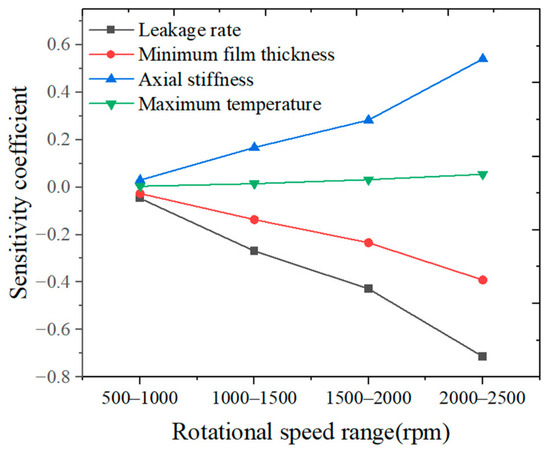
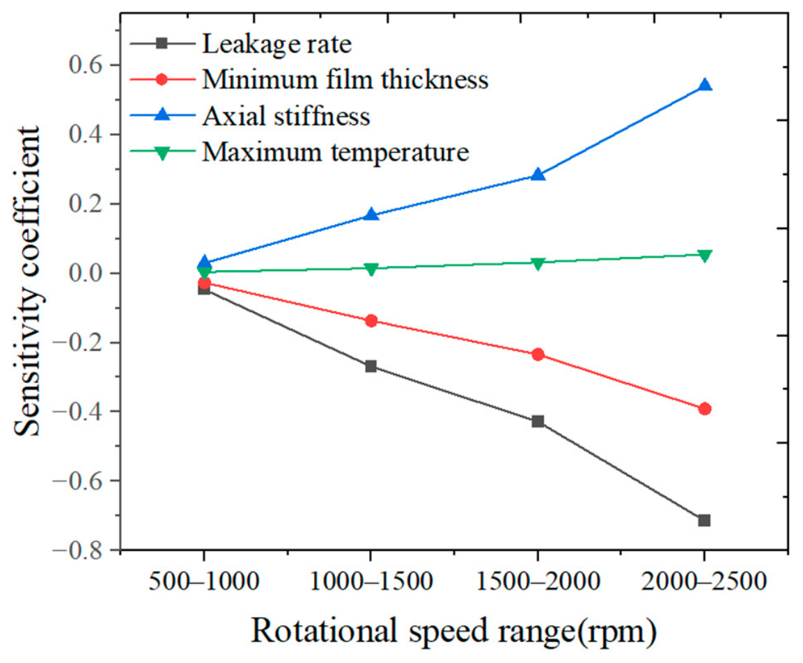
The sensitivity coefficients of the leakage rate, minimum thickness, axial stiffness, and maximum temperature of the fluid film with respect to rotational speed are presented in Figure 22. It can be seen that significant upward trends occur in the sensitivity coefficients of the performance parameters with respect to rotational speed. Specifically, the sensitivity coefficients of the leakage rate and minimum film thickness with respect to rotational speed increase in magnitude from 0.047 to 0.71 and from 0.027 to 0.39, respectively. Although the absolute values of the sensitivity coefficients of the leakage rate with respect to rotational speed are lower than those to fluid pressure and spring specific pressure, the monotonically increasing trend in magnitude indicates that the influence of rotational speed on leakage rate becomes more pronounced at higher speeds. In contrast, the sensitivity coefficients of axial stiffness and maximum temperature of the fluid film increase from 0.029 to 0.54 and from 0.0042 to 0.054, respectively. The maximum temperature of the fluid film has relatively low sensitivity to variation in the rotational speed. In summary, rotational speed exerts a more pronounced influence on the leakage rate under the given operating conditions, especially at high speeds, while its impact on the maximum temperature of the fluid film remains relatively insignificant.
Figure 22.
The sensitivity coefficients of the performance parameters under different rotational speeds.
Based on the above-mentioned analysis of the sensitivity coefficients of the performance parameters under different operating conditions, the leakage rate exhibits the most significant sensitivity to the operating parameters, including fluid pressure, spring specific pressure, and rotational speed, while the maximum temperature of the fluid film presents the lowest sensitivity. Specifically, under the given operating conditions, the leakage rate is most sensitive to fluid pressure (with a sensitivity coefficient reaching 12.04), moderately and stably sensitive to spring specific pressure (with a sensitivity coefficient of approximately −2.0), and least sensitive to rotational speed (with a maximum sensitivity coefficient magnitude of approximately 0.7), although its influence intensifies at higher speeds. By comparison, the maximum sensitivity coefficient of the maximum fluid film temperature is merely approximately 0.054 within the given range.
In contrast, the sensitivities of the axial stiffness and minimum film thickness exhibit an intermediate trend under different operating conditions. However, under a relatively high-pressure range (larger than 12 MPa), the sensitivity coefficient of the minimum film thickness reaches up to 2.14, which exceeds the maximum magnitude of the sensitivity coefficient of the axial stiffness (approximately 1.46) in the given pressure range. Conversely, when considering variations in spring specific pressure and rotational speed, the axial stiffness is relatively more sensitive to these operating parameters than the minimum film thickness.
4. Conclusions
In the paper, a 3D TEHD model of the high-pressure deep-grooved mechanical seal was presented. Based on this model, the thermo-mechanical coupling deformation characteristics of the seal face and sealing performance were investigated by using FEM under different operating conditions. The results demonstrate that the deep-grooved face seal modifies the pressure and temperature distributions of the fluid film and induces the circumferential waviness deformation of the seal face, thereby generating the hydrodynamic wedge effect. The hydrodynamic wedge effect is primarily dominated by the axial mechanical deformation along the circumferential direction, and the axial thermal deformation along the circumferential direction plays a relatively minor role due to the small temperature difference across the seal face. In contrast, a significant hydrostatic effect produced by the thermo-mechanical coupling deformation of the seal face along the radial direction dominates the load-carrying capacity of the fluid film, which is critical to guaranteeing the stable operation of the mechanical seal. The thermo-mechanical coupling deformation of the seal face decreases with increasing fluid pressure and increases as the spring force and rotational speed increase. Furthermore, the fluid pressure, spring force, and rotational speed exert a great influence on the sealing performance of the deep-grooved mechanical seal, with the leakage rate being the most sensitive to these operating parameters and the maximum temperature of the fluid film the least. Specifically, the leakage rate increases with increasing fluid pressure, whereas it decreases with increased spring force and rotational speed. The axial stiffness and maximum temperature of the fluid film increase with greater spring force and rotational speed, while decreasing with increasing fluid pressure. At a fluid pressure of 4 MPa, the leakage rate is about 0.023 L/h, and the axial stiffness of the fluid film is about 7.12 × 10⁸ N/m. These findings can serve as a theoretical reference for the design and development of high-pressure deep-grooved mechanical seals with enhanced stability.
Author Contributions
Conceptualization, X.M. and X.P.; methodology, W.Z. and X.M.; calculation, J.L. and W.Z.; validation, W.Z. and X.M.; formal analysis, J.L., W.Z., and X.M.; investigation, W.Z., X.M., and X.P.; resources, X.M. and X.P.; data curation, J.L. and W.Z.; writing—original draft preparation, J.L. and W.Z.; writing—review and editing, X.M., X.P., K.L., X.L., and S.D.; visualization, W.Z.; supervision, X.P. and K.L.; project administration, X.P. and K.L.; funding acquisition, W.Z., X.M., and X.P. All authors have read and agreed to the published version of the manuscript.
Funding
This research was supported by the National Key R&D Program of China, grant number 2024YFB3410501, and the National Natural Science Foundation of China, grant number U2241246.
Data Availability Statement
The original contributions presented in this study are included in the article. Further inquiries can be directed to the corresponding authors.
Conflicts of Interest
Authors J.L., K.L., X.L. and S.D. were employed by the company [Hefei General Machinery Research Institute Co., Ltd.]. The remaining authors declare that the research was conducted in the absence of any commercial or financial relationships that could be construed as a potential conflict of interest.
References
- Mayer, E. Performance of rotating high duty nuclear seals. Lubr. Eng. 1989, 45, 275–286. [Google Scholar]
- Fuse, T.; Shimizu, T.; Nishiyama, K. Development of high reliable mechanical seal for nuclear power plant. In Proceedings of the 17th International Conference on Fluid Sealing, York, UK, 8–10 April 2003; Available online: https://www.zhangqiaokeyan.com/academic-conference-foreign_meeting-252176_thesis/070508778115.html (accessed on 2 September 2026).
- Li, C.H. Thermal deformation in a mechanical face seal. ASLE Trans. 1976, 19, 146–152. [Google Scholar] [CrossRef] [Scilit]
- Blasiak, S. An analytical approach to heat transfer and thermal distortions in non-contacting face seals. Int. J. Heat Mass Transf. 2015, 81, 90–102. [Google Scholar] [CrossRef] [Scilit]
- Nyemeck, A.P.; Brunetiere, N.; Tournerie, B. Parametric study of the behavior of a mechanical face seal operating in mixed and TEHD lubrication regimes. In Proceedings of the ASME 11th Biennial Conference on Engineering Systems Design and Analysis, Nantes, France, 2–4 July 2012. [Google Scholar] [CrossRef] [Scilit]
- Brunetière, N.; Tournerie, B.; Frêne, J. TEHD lubrication of mechanical face seals in stable tracking mode: Part 1-Numerical model and experiments. J. Tribol. 2003, 125, 608–616. [Google Scholar] [CrossRef] [Scilit]
- Brunetière, N.; Tournerie, B.; Frêne, J. TEHD lubrication of mechanical face seals in stable tracking mode: Part 2-Parametric study. J. Tribol. 2003, 125, 617–627. [Google Scholar] [CrossRef] [Scilit]
- Thomas, S.; Brunetiere, N.; Tournerie, B. Thermoelastohydrodynamic behavior of mechanical gas face seals operating at high pressure. J. Tribol. 2007, 129, 841–850. [Google Scholar] [CrossRef] [Scilit]
- Meng, X.; Qiu, Y.; Ma, Y.; Peng, X. An investigation into the thermo-elasto-hydrodynamic effect of notched mechanical seals. Nucl. Eng. Technol. 2022, 54, 2173–2187. [Google Scholar] [CrossRef] [Scilit]
- Yang, X.; Peng, X.D.; Meng, X.K.; Jiang, J.B.; Wang, Y.M. Thermo-elasto-hydrodynamic analysis of triangular textured mechanical face seals. J. Zhejiang Univ.-Sci. A 2019, 20, 864–881. [Google Scholar] [CrossRef] [Scilit]
- Djamaï, A.; Brunetière, N.; Tournerie, B. Numerical modeling of thermohydrodynamic mechanical face seals. Tribol. Trans. 2010, 53, 414–425. [Google Scholar] [CrossRef] [Scilit]
- Liu, W.; Liu, Y.; Zhai, J.J.; Huang, W.F.; Wang, Y.M. Three-dimensional flow–heat coupling model of a wavy-tilt-dam mechanical seal. Tribol. Trans. 2013, 56, 1146–1155. [Google Scholar] [CrossRef] [Scilit]
- Liu, Y.; Liu, W.; Li, Y.J.; Liu, X.F.; Wang, Y.M. Mechanism of a wavy-tilt-dam mechanical seal under different working conditions. Tribol. Int. 2015, 90, 43–54. [Google Scholar] [CrossRef] [Scilit]
- Wen, S.Z.; Huang, P. Principles of Tribology; Tsinghua University Press: Beijing, China, 2012. [Google Scholar]
- Stefani, F.; Rebora, A. Steadily loaded journal bearings: Quasi-3D mass-energy-conserving analysis. Tribol. Int. 2009, 42, 448–460. [Google Scholar] [CrossRef] [Scilit]
- Becker, K.M. Measurements of convective heat transfer from a horizontal cylinder rotating in a tank of water. Int. J. Heat Mass Transf. 1963, 6, 1053–1062. [Google Scholar] [CrossRef] [Scilit]
- Ayadi, K.; Brunetière, N.; Tournerie, B.; Bouyer, J. Experimental thermal analysis of a mechanical face seal. J. Therm. Sci. Eng. Appl. 2016, 8, 031011. [Google Scholar] [CrossRef] [Scilit]
- Chaple, R.P.B. Numerical Stabilization of Convection-Diffusion-Reaction Problems. Delft, Delft Institute of Applied Mathematics, Delft University of Technology. 2006. Available online: https://www.semanticscholar.org/paper/Numerical-Stabilization-of-Convection-Diusion-R-Chaple/6616801720ca543e3f1baad6f21e57c5e10ca54d?p2df= (accessed on 2 September 2026).
- Meng, X.K.; Zhao, W.J.; Shen, M.X.; Peng, X.D. Thermohydrodynamic analysis on herringbone-grooved mechanical face seals with a quasi-3D model. Proc. Inst. Mech. Eng. Part J J. Eng. Tribol. 2018, 232, 1402–1414. [Google Scholar] [CrossRef] [Scilit]
- Qiu, Y.J. Study on Thermo-Hydrodynamic Wedge Effect of Notched End Face Mechanical Seals. Doctoral Dissertation, Zhejiang University of Technology, Hangzhou, China, 2022. [Google Scholar]
- Gu, Y.Q. Fluid Dynamic Sealing; Petroleum University Press: Shandong, China, 1990; ISBN 7-5636-0100-7. [Google Scholar]
- Nau, B.S.; Mayer, E. Mechanical Seals, 3rd ed.; Butterworth-Heinemann: Oxford, UK, 1977. [Google Scholar] [CrossRef] [Scilit]
- Mayer, E. Thermohydrodynamics in mechanical seals. In Proceedings of the 4th International Conference on Fluid Sealing, Philadelphia, PA, USA, 5–9 May 1969. [Google Scholar]

Disclaimer/Publisher’s Note: The statements, opinions and data contained in all publications are solely those of the individual author(s) and contributor(s) and not of MDPI and/or the editor(s). MDPI and/or the editor(s) disclaim responsibility for any injury to people or property resulting from any ideas, methods, instructions or products referred to in the content. |
© 2026 by the authors. Licensee MDPI, Basel, Switzerland. This article is an open access article distributed under the terms and conditions of the Creative Commons Attribution (CC BY) license.