


Abstract
Brush seals using compliant bristle packs can reduce turbomachinery leakage more effectively than conventional labyrinth seals, but their coupled structural and flow behavior makes design difficult. Under large pressure loading, bristles can deflect, lose contact with the rotor, and generate clearance, causing the sharp leakage increase known as blow-out. This study develops a model linking nonlinear bristle deflection, rotor–bristle contact loss, and leakage response. The bristle is treated as an inextensible nonlinear elastic member subjected to distributed pressure loading, backing-plate support, and frictional rotor contact. Contact and separated states are solved iteratively using boundary-value and initial-value solvers. Leakage through the bristle pack is calculated using a random bristle-bed formulation, and leakage through generated clearance is evaluated with an orifice-flow model. The model agrees well with published bristle-deflection predictions. Increasing pressure load reduces normal contact force until lift-off occurs, producing clearance and a sharp rise in leakage. Increasing front-plate free height shifted lift-off from pressure ratio ≈4 to ≈2, while clearance flow contributed up to 36.5% after lift-off. Brush-seal blowout is therefore governed by the transition from rotor–bristle contact to separation. Lower back-plate height can delay blow-out, but hysteresis and durability tradeoffs must be considered.
1. Introduction
Leakage control in turbomachinery remains closely linked to stage efficiency, secondary flow management, thermal loading, and rotor stability. Labyrinth seals are widely used because of their simple and robust non-contact construction, but their leakage performance is strongly governed by operating clearance and can deteriorate when rubbing, wear, or transient rotor motion changes the seal gap [1,2,3]. Brush seals were developed as compliant alternatives in which densely packed, inclined bristles form a flexible restriction near the rotor surface [1,4,5]. This bristle pack can maintain a small effective flow area while accommodating shaft excursions, and experimental and numerical comparisons have repeatedly treated brush-seals, hybrid brush seals, and labyrinth-brush arrangements as leakage-reduction concepts for gas-turbine, steam-turbine, and high-temperature annular sealing applications [2,3,6,7,8]. The same compliance, however, also makes brush seal performance a coupled fluid–structure contact problem; pressure loading, bristle–rotor interference, inter-bristle friction, backing-plate support, rotor motion, and thermal or wear processes can alter bristle shape and contact state, producing pressure stiffening, blow-down, hysteresis, heat generation, wear, clearance variation, and changes in leakage [9,10,11,12,13,14,15,16,17,18]. Consequently, leakage cannot be treated as a function of nominal geometry alone; it depends on the evolving mechanical state of the bristle tips and the pressure-loaded morphology of the bristle pack.
The development of brush seal analysis has therefore moved from bulk-flow and porous-medium descriptions toward coupled leakage, structural, and contact formulations. Hendricks et al. [4] presented an early bulk-flow model for brush seal systems, while Chew et al. [5] treated the bristle pack as an anisotropic porous medium coupled with bristle bending and contact forces. Turner et al. [19] combined clearance brush seal experiments with mathematical modeling, and Chen et al. [20] introduced an iterative CFD and mechanical model that linked pressure and flow predictions with bristle-pack deformation. In parallel, contact-focused studies established why bristle-tip interference, friction, and radial loading cannot be separated from leakage performance. Stango et al. [9] analyzed rotor–bristle interference using large-deformation cantilever mechanics with Coulomb friction at the bristle-tip/rotor interface, Zhao and Stango [10] extended the analysis to flow-induced radial load, and Cicone and Pascovici [21] compared linear and nonlinear radial-deformation descriptions for interference brush-seals. Later design studies expanded the available configurations beyond the conventional brush-seal by considering pressure-relief and back-plate effects, low-hysteresis and low-wear structures, helical-labyrinth-brush arrangements, variable bristle diameter concepts, and carbon-fiber brush-seals [2,13,14,22,23,24]. These configurations can reduce leakage, hysteresis, or wear under selected conditions, but the cited studies also show that their benefit depends on how the architecture redistributes pressure drop, modifies bristle-pack density or permeability, and changes the rotor–bristle contact state.
Geometry and operating conditions further control the balance between sealing performance and mechanical durability. CFD studies using porous-medium bristle-pack representations show that pressure ratio, pressure difference, clearance, and bristle-pack resistance influence leakage, and that geometric dimensions must be considered together rather than as isolated design variables [5,6,20,25]. Bristle lay angle affects leakage coefficient and leakage hysteresis in low-hysteresis brush-seals [26], while design parameter studies indicate that bristle-pack clamping, pack density, axial lay, and support geometry can alter gapping, permeability, and leakage [22]. Variable bristle diameter changes pack architecture and has been studied as a way to tailor leakage and mechanical response [23], while carbon-fiber brush seal experiments connect leakage performance with bristle-pack geometrical parameters under dry conditions [24]. For hybrid and modified seals, leakage also depends on the relative position of brush and labyrinth elements, the effective clearance, and the distribution of pressure drop through the seal [2,3,7]. Operating effects add another layer of coupling: pressure loading can drive blow-down and contact-force changes [10,14,15], rotor speed and eccentricity can influence dynamic contact and seal force [27], and frictional rubbing can generate heat and affect thermal loading at the bristle tip [17]. These findings collectively indicate that bristle diameter, bristle length, lay angle, pack density, fence height, front- and backing-plate geometry, interference or clearance, pressure loading, rotor speed, temperature, eccentricity, and bristle–rotor contact influence leakage through their effects on bristle deformation, contact force, hysteresis, wear, and the instantaneous leakage area [28].
Bristle-deflection models have developed along two related paths. The first uses beam-based analytical descriptions, often beginning with a single bristle under prescribed tip force, interference, distributed pressure load, or frictional contact. This approach provides transparent relations between geometry, stiffness, stress, and contact force, but it depends on assumptions about support constraints, contact location, friction, and whether deformation remains small [5,9,10,16,21]. The second path uses numerical or coupled models to represent bristle-pack behavior, porous leakage, pressure loading, and multiple contact interfaces. Early coupled flow-structure models linked porous flow predictions with bristle bending and pack mechanics [4,5,19,20], while later finite element and contact analyses emphasized bristle–bristle, bristle–backing-plate, and bristle–rotor interactions when estimating stiffness, stress, and contact load [11,13,16,29]. Changizi et al. [30] formulated a nonlinear analytical model for brush-seal bristles using large-deflection beam theory and generalized loading, further demonstrating that nonlinear elasticity is relevant when brush elements are subjected to complex static and dynamic loads. Wei et al. [27] recently introduced a nonlinear contact mechanics model for a single bristle and coupled the resulting brush-seal axial force with rotor-system dynamics, including the effects of hysteresis, bristle interference, rotor speed, and eccentricity. The literature therefore contains both efficient linearized models and more complete nonlinear/contact formulations; the limitation of simplified linear models is not that they are never useful, but that they cannot by themselves describe changes in contact condition, frictional hang-up, pressure-induced bristle-pack rearrangement, or rotor–bristle separation when these effects dominate leakage.
A specific unresolved issue is the coupling between pressure-loaded bristle deflection, bristle-tip contact loss, and leakage. Phan et al. [12] showed that frictional hysteresis can leave an opening gap after shaft displacement and that this gap increases leakage unless the pressure loading changes sufficiently, while Ha et al. [7] demonstrated the sensitivity of leakage prediction to rotor-seal clearance in a worn or deflected hybrid brush-seal. Blow-down studies show that pressure load can compact the bristle pack and move bristle tips toward the rotor, but pressure-relief, back-plate geometry, clearance, and bristle-row position can change the magnitude and distribution of that deflection [14,15,24,25]. Existing contact-mechanics, structural, and nonlinear-dynamics models provide important descriptions of bristle force, hysteresis, pressure stiffening, stress, and rotor response, but they generally focus on the force-deformation/contact state or on leakage through a prescribed effective clearance rather than on explicitly coupling pressure-induced bristle-tip separation from the rotor with the associated abrupt leakage increase. To the authors’ knowledge, previous nonlinear bristle-deflection models have not explicitly coupled pressure-induced bristle-tip separation from the rotor with the resulting abrupt increase in leakage. The objective of the present study is therefore to develop a nonlinear bristle-deflection model that considers both bristle deformation and contact mechanics between the rotor and the bristle tip. In the proposed framework, increasing pressure load can drive the bristle toward a state in which the tip separates from the rotor surface, creating an effective clearance. By connecting this bristle-tip separation to leakage behavior, the model aims to describe a pressure-dependent transition that is not captured when contact is assumed to persist or when leakage is evaluated only from a fixed geometric clearance.
2. Theoretical Model
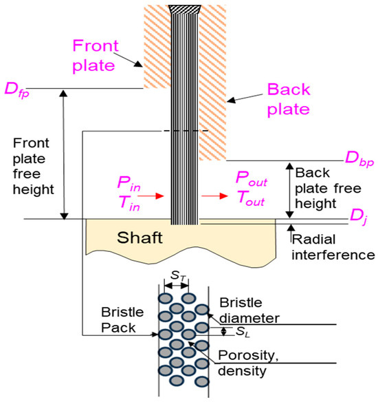
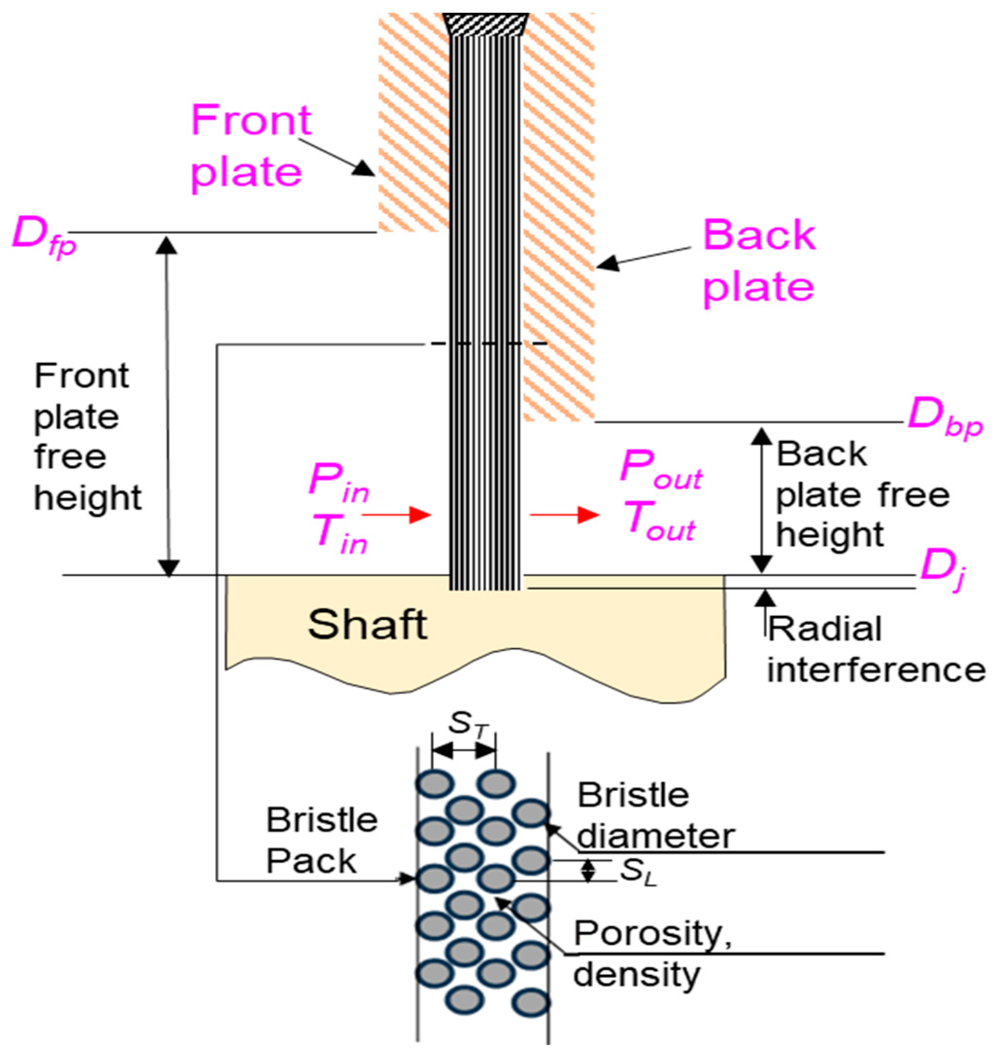
Figure 1 shows the axial schematic view of the brush-seal along with the nomenclature. The bristles under the influence of pressure differential load deflect while trying to prevent leakage and maintain contact with the rotor surface. Therefore, the present study treats the brush seal leakage problem using a sequentially coupled framework in which the prescribed pressure difference first determines the bristle deflection and rotor–bristle contact state, and the resulting contact or lift-off condition is then used to evaluate the leakage response. The leakage component contains two flow paths: leakage through the bristle pack and leakage through a generated clearance between the rotor and the bristle tip as a result of bristle deflection. The bristle-pack leakage model follows the randomly distributed bristle-bed formulation of Chupp and Holle [31].
Figure 1.
Typical configuration of a brush seal with nomenclature.
2.1. Leakage Through the Bristle Pack
The bristle pack is modeled as a randomly distributed bristle bed that imposes a distributed flow resistance on the leakage path. The leakage through the bristle bed is determined by the product of the mass flux, the flow area, and the porosity of the bristle pack.
where ε, Ab, and G are the porosity, flow area, and the mass flux through the bristle bed, respectively. The porosity can be quantified as the fraction of the reference volume not occupied by the bristle material. Mathematically, it can be defined as the ratio of the free volume to the total volume in the bristle region as follows,
where is the minimum effective brush thickness and λ is the bristle lay angle. Note that the porosity ε and the minimum pack thickness Bmin are calculated from the initial bristle-pack geometry and held constant during the leakage calculation.
In Equation (1), the flow area can be calculated based on the back-plate free height, Lbf, represented by Dbf, given as follows,
where Dbf is the diameter corresponding to the back-plate free height, Dj is the journal diameter, and Dt = Dj + 2Δh is the deflected bristle tip diameter. Δh is the clearance generated as a result of the bristle deflection.
Finally, the mass flux G in Equation (1) can be modeled as a function of the pressure difference and brush geometry derived empirically for the laminar and turbulent flow conditions.
where Pin, Pout, ρ, gc, and f are inlet pressure, exit pressure, fluid density, gravitational constant, and friction factor, respectively. STm and SL represent the spacing in the transverse and longitudinal directions, respectively, as shown in Figure 1 and Dhv is the volumetric hydraulic (effective) diameter.
The friction factor f as a function of the Reynolds number Re in Equation (4) differentiates between the laminar and turbulent flow models and can be calculated as follows,
2.2. Leakage Through Clearance
The second leakage path appears when pressure-induced bristle deflection in the axial direction results in the generation of a clearance between the rotor and the bristle tip. The leakage through the generated clearance is modeled as flow through an orifice for unchoked and choked conditions, given as follows.
where Cd, Pin, and Tin are the discharge coefficient, inlet pressure, and inlet temperature, respectively. γ = 1.4 is the specific heat ratio of the air, Pr is the ratio of the inlet to the outlet pressure, and Pchoke = (2/(γ+1))γ/(γ−1) = 0.528 is the choke pressure ratio condition. The effective flow area Ac for the generated clearance can be given as,
2.3. Bristle Deflection
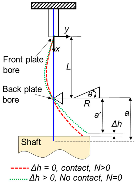
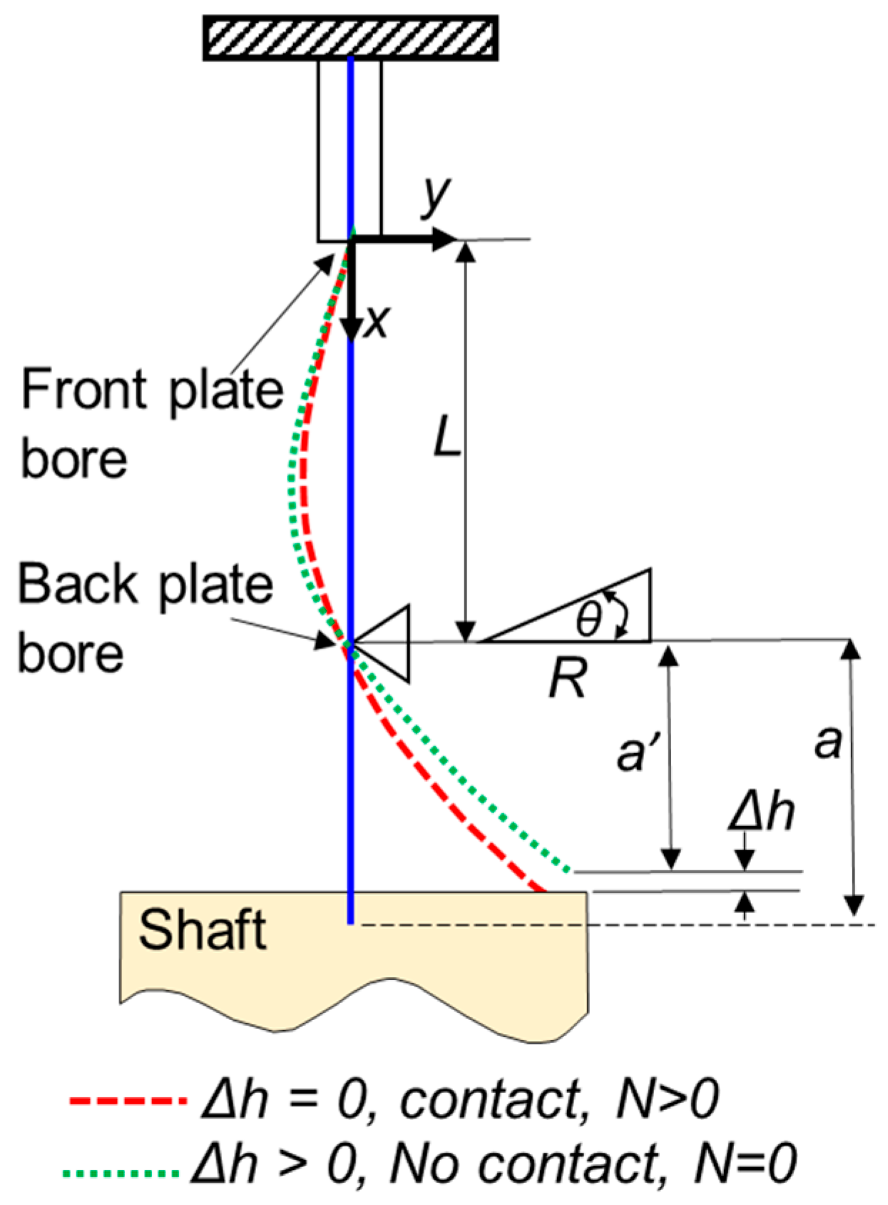
Most of the studies use linear elastic theory considering the bristle as a cantilever beam to model the bristle-deflection. However, large pressure differentials cause large deflections, making linear theory void; thus, the application of the nonlinear elastic theory becomes inevitable. The current study modifies the nonlinear bristle deflection framework of Modi [32], in which the bristle deformation is described by a nonlinear elastica equation and constrained by the support and contact conditions. The nonlinear deflection model describes the bristle as an inextensible elastic member subjected to axial pressure loading, support reactions, and rotor–bristle interaction. Figure 2 shows the coordinate system and contact states.
Figure 2.
Coordinate system and contact/separation states for the nonlinear bristle-deflection model.
The nonlinear elastic relation that relates the curvature of the deflected bristle centerline to the bending moment can be given as follows,
where the left-hand side represents the curvature of the bristle centerline, while M(x), E, and I are the bending moment, Young’s modulus, and second moment of inertia. The bending moment M(x) is decomposed into the pressure-load moment Mq and contact-load moment Mc,
The piecewise pressure-load moment Mq for the two segments of the bristle, i.e., (i) 0 < x < L, and (ii) L < x < L + a can be given as follows,
where a′, L, x, R, y, and θ are the bristle tip’s radial excursion, bristle length from root to the back-plate bore, coordinate along bristle length, support reaction, axial coordinate, and support reaction angle, respectively. q = (Db2/Bt)ΔP is the distributed pressure load per unit bristle length, where Db and Bt are the bristle diameter and bristle pack thickness, respectively. The moment Mc due to the forces generated by the contact between the bristle tip and the rotor surface can be given as follows,
where N represents the normal force and µf is the coefficient of friction. xtip and ytip represent the bristle tip coordinates. Note that the rotor–bristle contact mechanics determine whether the bristle tip remains in contact with the rotor surface (N > 0) or separates (N = 0) under pressure loading.
2.4. Boundary Conditions for the Solution of Moment Equation
Equation (8) is a second-order differential equation, and there are three unknowns in Equations (8)–(11); therefore, five boundary conditions are required to solve the problem. As shown in Figure 2, x = 0 is located at the front-plate bore location. The current model treats this front-plate bore as a restrained kinematic support, where zero transverse displacement and zero slope are imposed. This boundary condition represents a simplified restrained-support assumption and does not explicitly model unilateral front-plate contact, possible rotation at the support, or changing support reactions. Such a restrained-end representation is consistent with the simplified single-bristle beam idealizations commonly used to estimate brush seal bristle deflection and contact force, where the bristle is treated as a cantilever or fixed-end beam [9,16,21,29].
Similarly, the back plate provides support; thus, deflection is considered equal to zero at the backing-plate bore, and the slope at the backing-plate location is equal to the tangent of the support reaction angle θ. In addition, the bristle is considered inextensible, so the original non-deflected length and the arc length of the deflected bristle are assumed equal. Equation (12) summarizes the boundary and constraint conditions as follows:
2.5. Normalization of Model Parameters
The leakage flow rate is characterized using the flow factor, defined as
where Tin, Pin, and Dj are the inlet fluid temperature, inlet fluid pressure, and journal diameter, respectively. This normalization removes the direct influence of inlet pressure, inlet temperature, and journal diameter from the leakage flow rate, allowing the leakage response under different operating conditions to be compared more consistently.
Similarly, following Modi’s formulation [32], the pressure load q acting on the bristle is normalized using the flexural rigidity of the bristle. The coordinate along the bristle length x and the axial deflection coordinate y are also normalized using the bristle length L from the front-plate bore to the back-plate bore. The normalized quantities are defined as,
where C is the non-dimensional pressure load, Lb is the back-plate free height, E is Young’s modulus, and I is the second moment of area of the bristle. The parameter a represents the characteristic radial length used in the bristle lift-off model, defined as the sum of the backing-plate free height and the initial interference length.
3. Numerical Methods
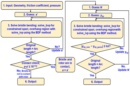
The solution procedure starts with the prescription of the brush-seal geometry, bristle material properties, and operating conditions. Before calculating the leakage, the nonlinear bristle-deflection equation is solved to determine whether the bristle tip remains in contact with the rotor surface or lifts off from it. Figure 3 shows the flow chart of the solution procedure for the nonlinear bristle-deflection model.
Figure 3.
Flow chart of the numerical procedure for the solution of the bristle deflection.
Each step in the flow chart given in Figure 3 can be briefly explained as follows.
3.1. Numerical Procedure Steps for Separated Case
- Input: The brush-seal geometry, bristle material properties, and operating conditions are specified.
- Initial guess: The solution procedure starts by assuming that the bristle tip is separated from the rotor surface. Therefore, an initial value of the radial excursion of the bristle tip, a′, is guessed. Since the bristle and rotor are not in contact in this case, the normal contact force N is set equal to zero.
- Solve bristle bending: The nonlinear bristle bending equation is solved numerically. The constrained part of the bristle is solved using the boundary value problem solver solve_bvp from SciPy version 1.16.3, while the overhung part is solved using solve_ivp. Since the normal force is zero in the separated case, only the pressure-load moment is included in the bending moment equation.
- Arc-length convergence check: The arc length of the deflected bristle is calculated and compared with the actual bristle length. The assumed value of a′ is updated iteratively until the difference between the calculated arc length and the actual bristle length becomes smaller than the prescribed tolerance.
- Contact check: After convergence of the arc-length condition, the contact state is checked by comparing a and a′. If the difference between them is greater than the prescribed tolerance, the bristle tip is considered separated from the rotor surface, and the radial difference Δh = max(a − a′, 0) is taken as the generated clearance. If the difference is smaller than the tolerance, the bristle tip is assumed to be in contact with the rotor surface, and the solution procedure is shifted to the contact case.
- Output: The final output of the separated case is the bristle-deflection shape and the generated clearance between the bristle tip and rotor surface.
3.2. Numerical Procedure Steps for Contact Case
- Initial guess of normal force N: In the contact case, the normal force is no longer zero. Therefore, the solution procedure starts with an initial guess of the normal contact force N. Since the bristle tip is assumed to be in contact with the rotor surface a′ is set equal to a.
- Initial guess of bristle-tip coordinate: The contact moment depends on the bristle-tip coordinates and the friction force. Therefore, an initial value of the bristle-tip coordinate ytip is also assumed. The bristle-tip coordinate is updated during the iterative solution because it depends on the calculated deflected shape of the bristle.
- Solve bristle bending: Similar to the separated case, the nonlinear bristle bending equation is solved for the constrained and overhung regions using SciPy’s numerical solvers. In this case, both the pressure-load moment and the contact-load moment are included in the bending moment equation.
- Convergence check for ytip: The value of ytip calculated from the bristle-deflection solution is compared with the initially assumed value. The iteration is repeated until the difference between the assumed and calculated values of ytip becomes smaller than the prescribed tolerance.
- Convergence check for N: After the bristle-tip coordinate is converged, the arc-length condition is checked. The normal force N is updated iteratively until the calculated arc length satisfies the inextensibility condition of the bristle. If the converged value of N becomes negative, the assumed contact condition is physically invalid, and the solution is treated as a separated case.
- Output: The final output of the contact case is the bristle-deflection shape and the normal contact force acting between the bristle tip and rotor surface.
Once the bristle deflection is obtained, the leakage through the bristle bed is calculated using the bristle-bed leakage equations (Equations (1)–(5)). In this leakage model, the mass flux G, Reynolds number Re, and friction factor f are interdependent. Therefore, the calculation is performed iteratively. First, an initial value of the friction factor is assumed. Then, the mass flux G is calculated, the Reynolds number Re is updated, and a new value of friction factor f is obtained from the corresponding laminar or turbulent friction-factor relation. Under-relaxation is applied during this process to improve numerical stability, and the iteration is continued until the change in G or f becomes smaller than the prescribed convergence tolerance.
If the bristle deflection generates a clearance between the bristle tip and rotor surface, the leakage through this clearance is calculated using the orifice-flow model. The generated clearance determines the effective flow area in the leakage through the orifice equation. Thus, for each prescribed pressure ratio, the present formulation provides a quasi-static equilibrium solution for the bristle contact state, generated clearance, and corresponding leakage response under an axisymmetric mean geometry and uniform circumferential pressure loading. Transient or cyclic pressure loading, bristle inertia, rate-dependent friction, vibration, hysteresis, thermal effects, wear, rotor eccentricity, and non-axisymmetric pressure loading are outside the scope of the present study. Under such conditions, local variations in interference, contact force, generated clearance, and leakage may occur, and local lift-off or blow-out may begin at lower pressure ratios than those predicted by the present circumferentially uniform model.
4. Results
The results are presented in normalized form to emphasize the governing trends in bristle deflection, rotor–bristle contact, generated clearance, and leakage response without depending on the dimensional scale of a specific brush-seal geometry. The pressure load is expressed using the non-dimensional load parameter C defined in Equation (14). The leakage response is represented by the flow factor φ as a function of the pressure ratio. The front- and back-plate free heights and the radial interference are reported as normalized design variables over the investigated parametric range. The dimensional input values are therefore not tabulated; instead, the analysis focuses on the normalized trends relevant to the onset of lift-off and leakage increase. The radial interference between the rotor and bristle, the back-plate free height, and the front-plate free height were varied to evaluate their effects on bristle deflection, rotor–bristle contact state, generated clearance, and leakage performance. Before conducting the parametric study, the baseline bristle-deflection model was validated against the predictions reported in Ref. [32].
4.1. Bristle-Deflection Model Verification Against Published Bristle-Deflection Prediction
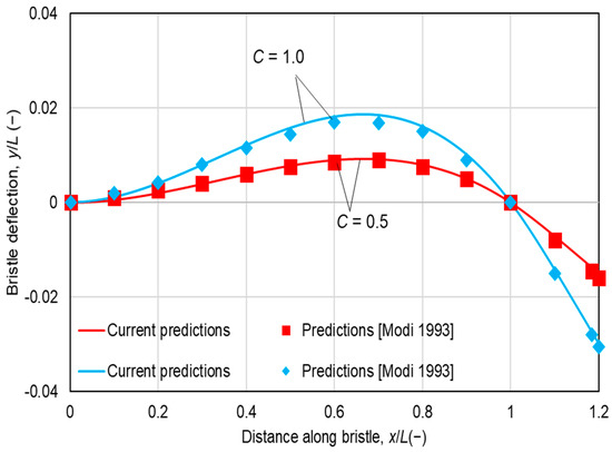
Figure 4 compares the predicted normalized axial bristle-deflection profiles with the results of Ref. [32] for the non-dimensional pressure loads of C = 0.5, and C = 1. As expected, increasing C increases the axial deflection of the bristle. The present model shows good agreement with the published predictions for both normalized pressure-difference cases, confirming that the nonlinear deflection formulation can reproduce the reference bristle response.
Figure 4.
Normalized bristle axial deflection y/L vs. normalized distance along bristle length x/L for normalized pressure load C = 0.5 and C = 1.0. Lb/L = 0.2. Current predictions compared to predictions in Ref. [32].
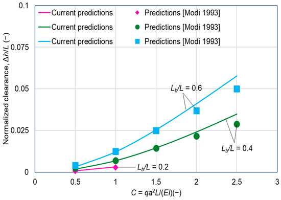
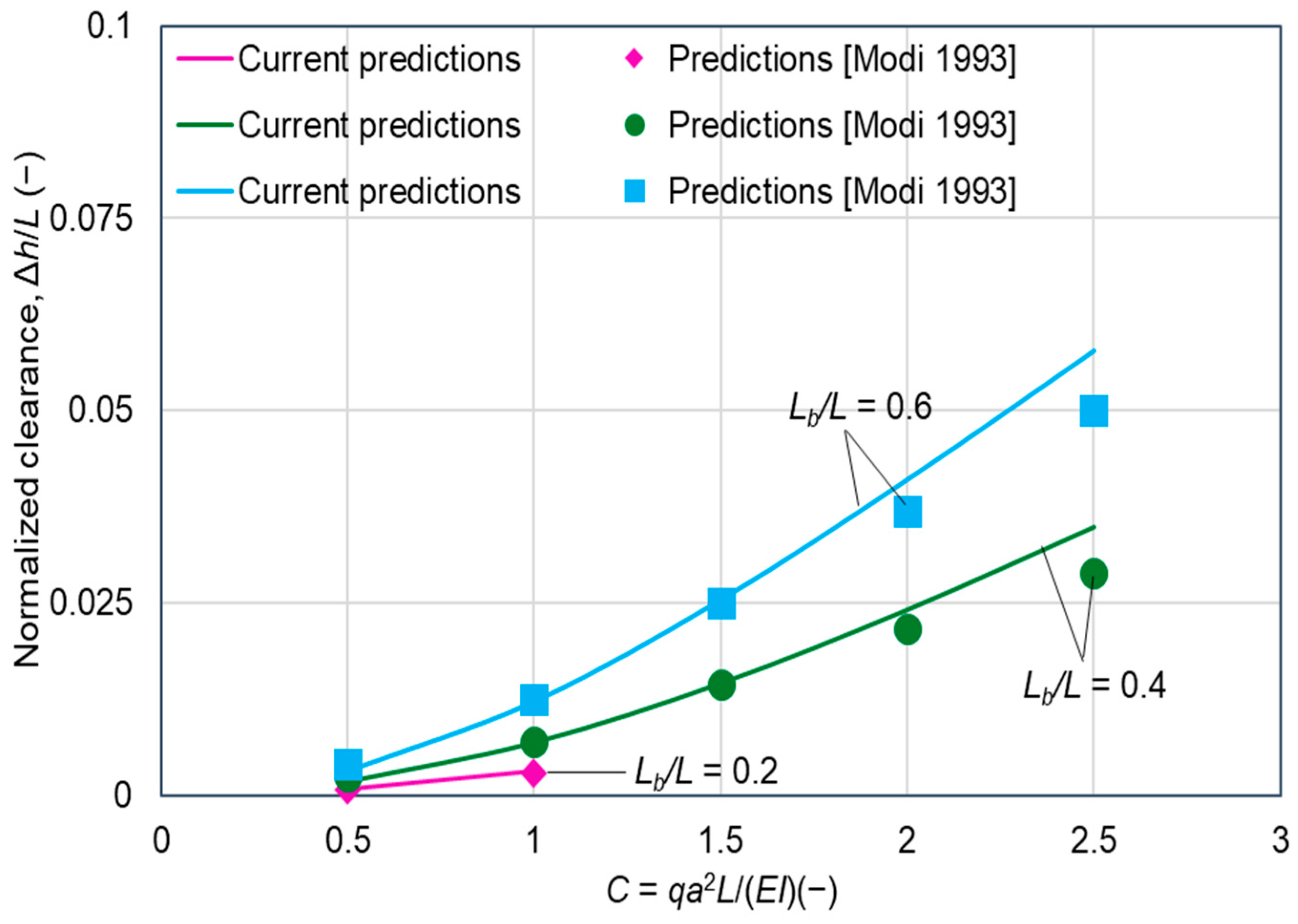
Figure 5 shows the normalized generated clearance caused by bristle deflection as a function of the non-dimensional pressure load for increasing normalized back-plate free height. As the back-plate free height increases, the effective moment arm of the overhung bristle region becomes larger, resulting in greater axial deflection and increased clearance between the rotor and the bristle tip. The present predictions generally agree well with Ref. [32], although a slight deviation appears at the larger back-plate height under high pressure loading.
Figure 5.
Normalized generated clearance due to bristle deflection vs. normalized pressure load for increasing normalized back-plate height. Current predictions compared to predictions in Ref. [32].
4.2. Effect of Pressure Differential Load on Rotor–Bristle Contact Mechanics
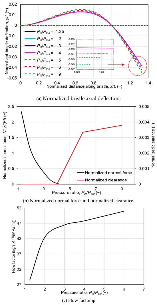
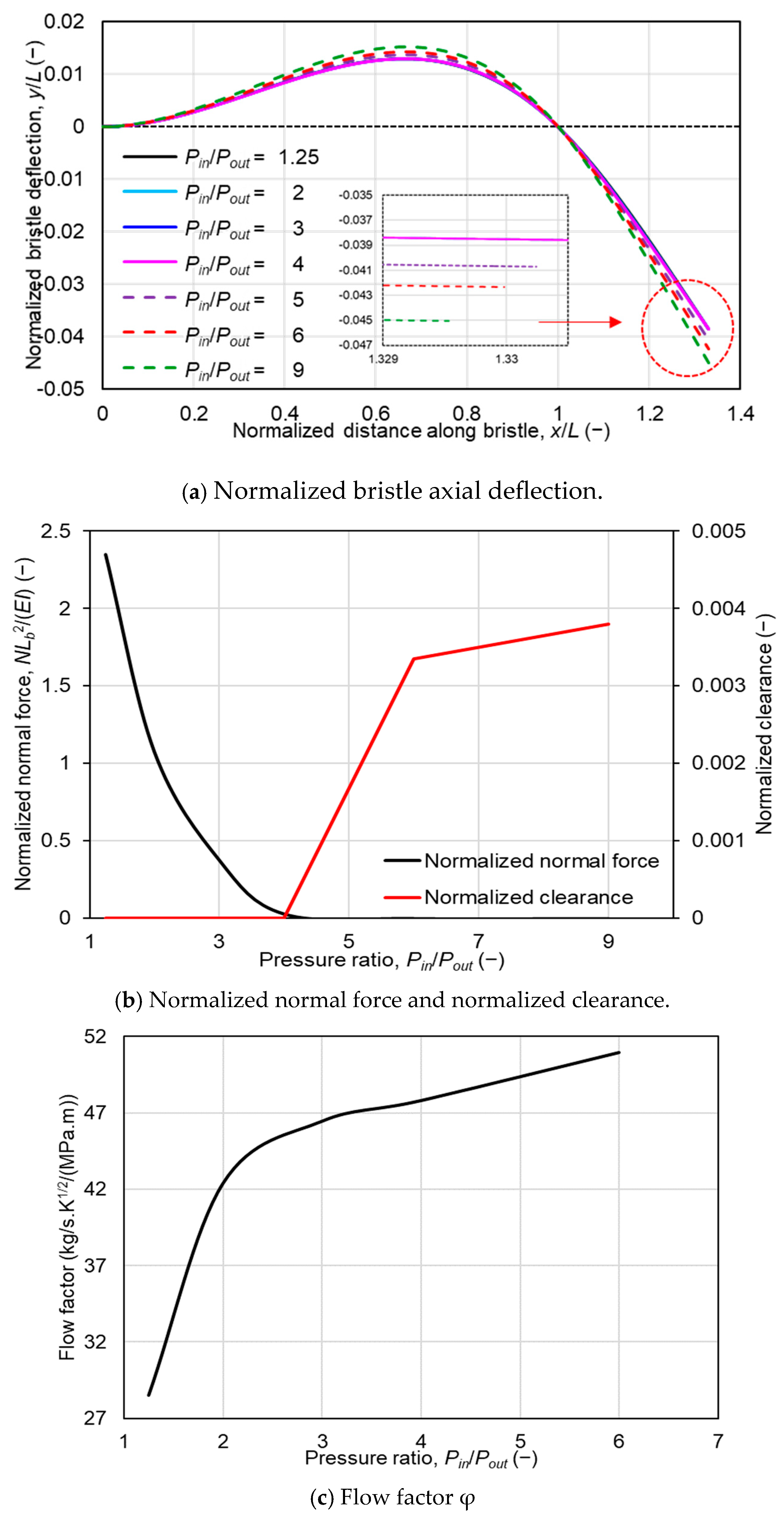
The effect of non-dimensional pressure load on bristle deflection, normal contact force, generated clearance, and leakage response is shown in Figure 6. The normalized back-plate free height Lb/L is 0.33 and the normalized front-plate free height Lf/L = 1.333.
Figure 6.
(a) Normalized bristle axial deflection profile vs. normalized distance along bristle length for increasing pressure ratio; (b) normalized normal force (primary axis) and normalized clearance due to deflection (secondary axis) vs. pressure ratio; and (c) leakage flow factor φ vs. pressure ratio. Lb/L = 0.33, and Lf/L = 1.33.
As shown in Figure 6a, the normalized bristle deflection increases gradually with pressure ratio Pin/Pout while the bristle tip remains in contact with the rotor surface as the rotor–bristle contact force opposes the pressure-induced bending of the bristle. Beyond approximately Pin/Pout = 4, the bristle tip lifts off from the rotor surface. After the lift-off, the opposing contact moment is removed, and the bristle deflection increases more rapidly with further pressure loading.
Figure 6b shows the corresponding variation in normalized normal force and normalized generated clearance. The normal force decreases with increasing pressure ratio Pin/Pout and becomes zero at the lift-off condition. Once the normal force reaches zero, rotor–bristle contact is lost, and a clearance is generated between the bristle tip and the rotor surface. This clearance continues to increase as the pressure load increases.
Figure 6c shows the resulting leakage behavior in the form of a flow factor φ. Before lift-off, φ increases gradually because leakage occurs mainly through the bristle pack. After lift-off, the generated clearance provides an additional leakage path, causing a sharp increase in φ. Additionally, the clearance-flow contribution increases with the generated clearance and reaches approximately 6% of the total leakage; however, the bristle-pack leakage remains the dominant leakage path. This result indicates that the transition from contact to separation is a critical mechanism governing brush-seal blow-out. Note that blow-out refers to pressure-induced axial bristle deflection leading to lift-off and clearance generation, whereas blow-down, which is not considered in the present model, refers to radial bristle motion toward the rotor.
4.3. Effects of Front-Plate and Back-Plate Heights on Leakage Performance of Brush Seal
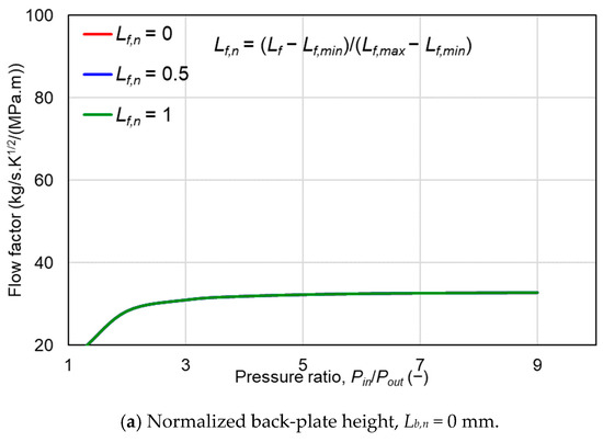
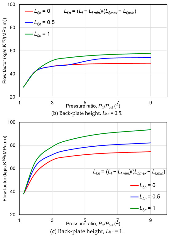
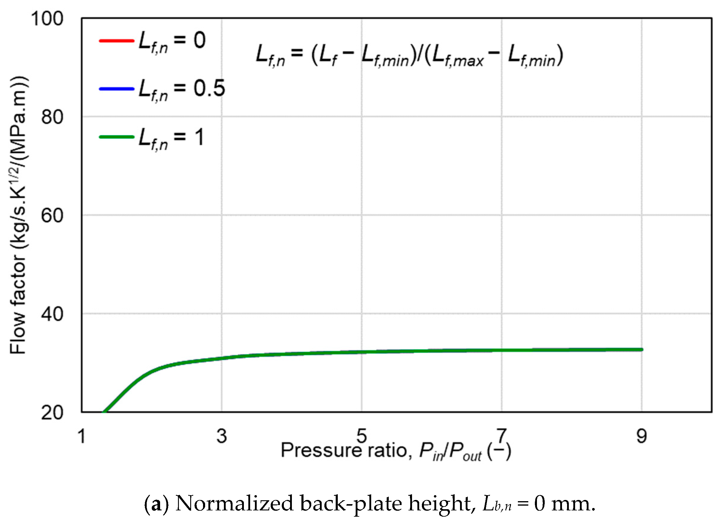
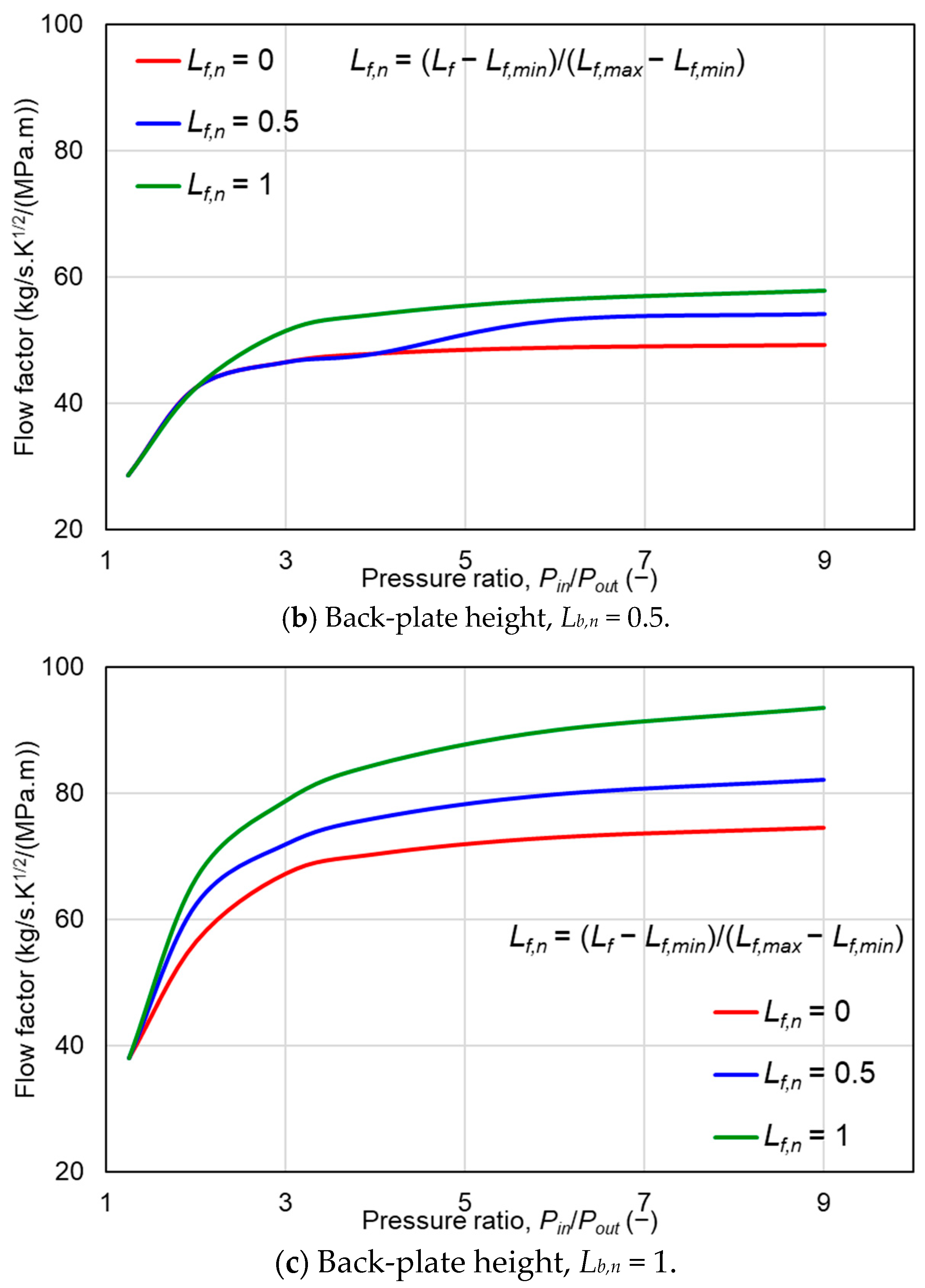
Figure 7 shows the flow factor φ as a function of the pressure ratio for different normalized front- and back-plate free heights. Note that the front-plate free height Lf and back-plate free height Lb are reported as normalized design variables based on the minimum and maximum values considered in the parametric study, i.e., Lf,n = (Lf − Lf,min)/(Lf,max − Lf,min) and Lb,n = (Lb − Lb,min)/(Lb,max − Lb,min). The results demonstrate that the leakage behavior is strongly affected by the support geometry because the front- and back-plate heights influence the deflection of the overhung bristle region and the onset of rotor–bristle separation. For Lb,n = 0, the φ curves for different front-plate free heights remain nearly unchanged over the analyzed pressure range, as shown in Figure 7a. This indicates that the bristle tip remains in contact with the rotor surface, preventing the formation of a clearance leakage path. In this case, leakage is mainly governed by flow through the bristle pack. As shown in Figure 7b, for Lb,n = 0.5, the effect of front-plate free height becomes more significant. When Lf,n = 0.5, the leakage flow rate increases sharply after approximately a pressure ratio of 4, indicating the onset of bristle lift-off. With a further increase in Lf,n to 1, lift-off occurs earlier, at approximately a pressure ratio of 2. This shows that increasing the front-plate free height promotes bristle deflection and shifts the lift-off condition to a lower pressure ratio. Similarly, as shown in Figure 7c, for Lb,n = 1, the onset of lift-off shifts further to lower ratios. The increased back-plate free height enlarges the effective moment arm of the overhung bristle region, which increases pressure-induced deflection and promotes earlier separation from the rotor surface. Moreover, comparison of the two leakage paths shows that, after lift-off, the clearance-flow contribution varies from approximately 10% to 36.5% of the total leakage, while the bristle-pack leakage remains the dominant contribution over most of the investigated range.
Figure 7.
Leakage flow factor φ vs. pressure ratio for increasing normalized front plate height at (a) normalized back-plate height Lb,n = 0; (b) normalized back-plate height, Lb,n = 0.5; and (c) normalized back-plate height, Lb,n = 1.
Overall, increasing either the front-plate or back-plate free height tends to promote bristle lift-off and increase leakage. The back-plate free height has a particularly strong influence because it affects both the effective bristle leakage area and the pressure-induced deformation of the overhung bristle section.
4.4. Effects of Radial Interference Between Rotor and Bristle on Brush-Seal Performance
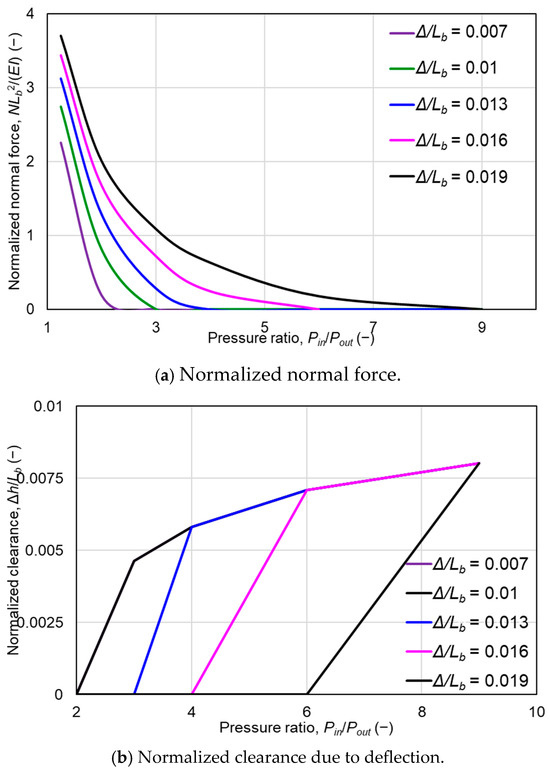
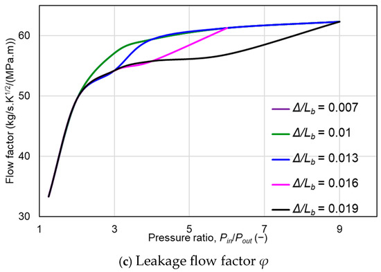
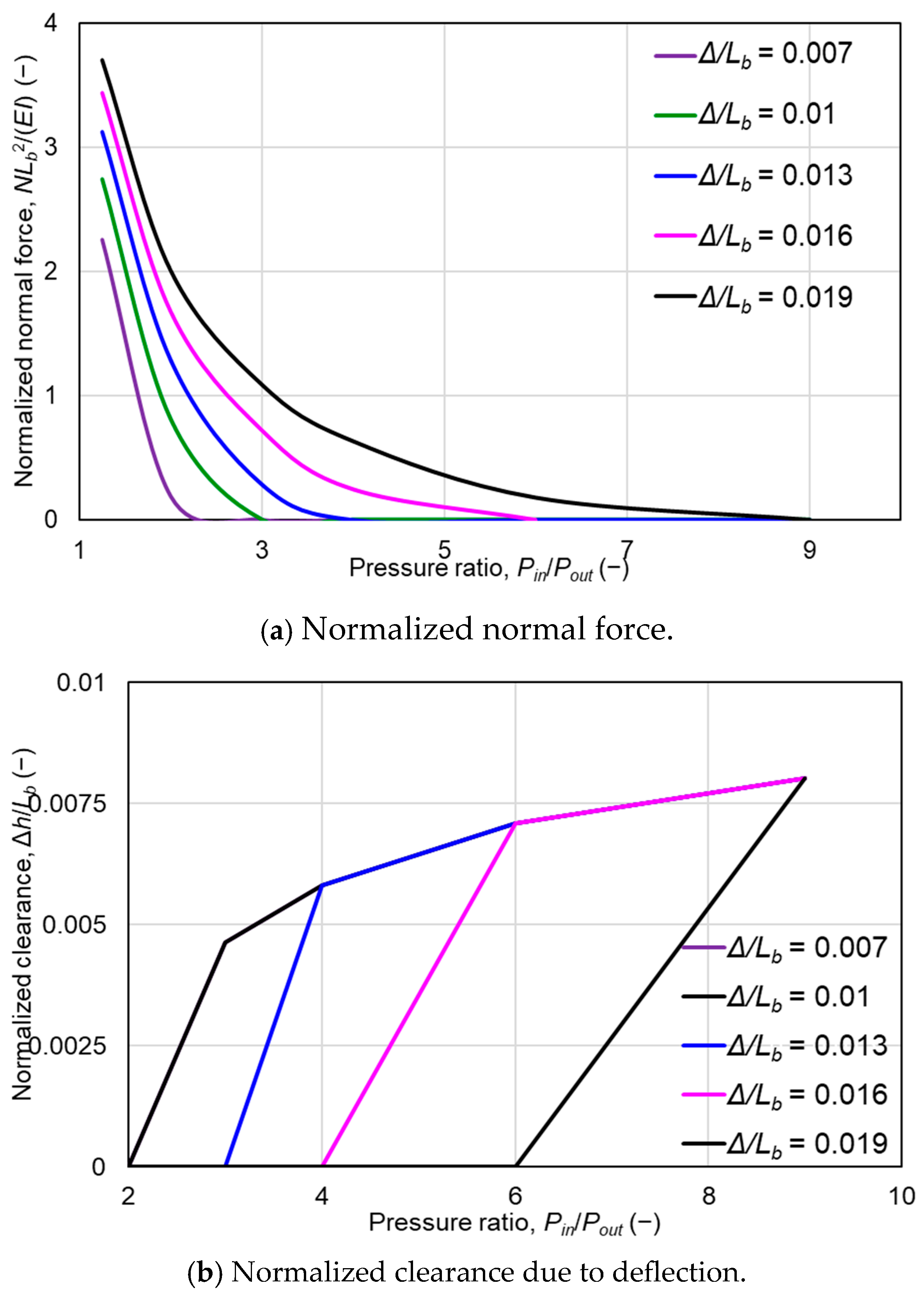
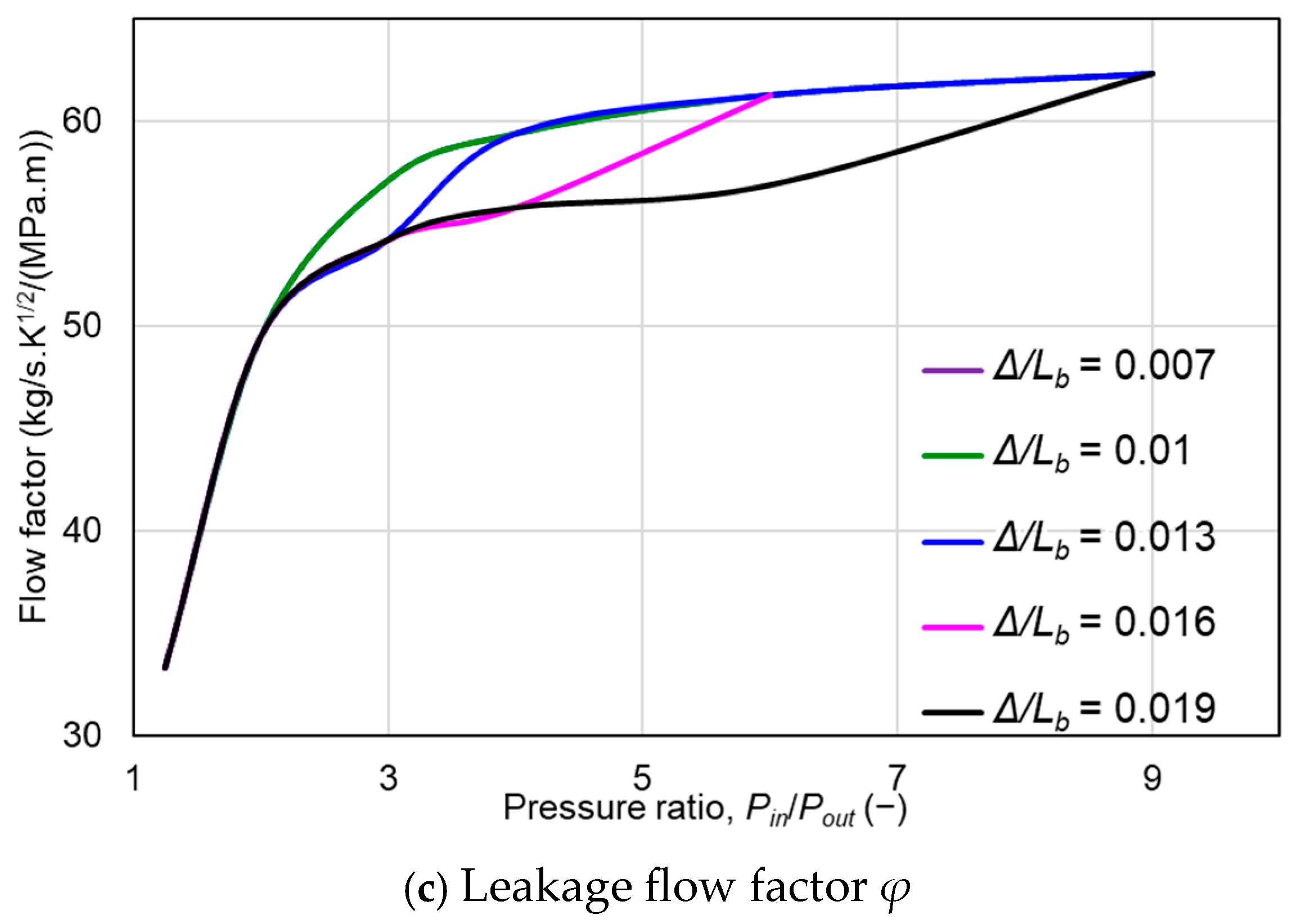
This section presents the effects of the normalized radial interference Δ/L between rotor and bristle on the rotor–bristle contact mechanics and leakage performance of the brush seal. Figure 8 shows the (a) normalized normal force; (b) normalized clearance generated due to the bristle deflection; and (c) flow factor plotted against the pressure ratio. The normalized back-plate height Lb/L = 0.4, and the normalized front plate height Lf/L = 1.4. As shown in Figure 8a, the normalized normal contact force increases with increasing radial interference. This occurs because larger interference produces stronger mechanical interaction between the bristle tip and the rotor surface. As a result, a larger pressure difference is required to reduce the normal force to zero and initiate bristle lift-off. Similarly, the normalized generated clearance shown in Figure 8b depends strongly on the radial interference. Smaller interference allows the bristle tip to separate from the rotor at a lower pressure load, resulting in earlier clearance generation. In contrast, larger interference delays lift-off because the bristle remains in contact with the rotor over a wider pressure range. After lift-off, the clearance trends become less sensitive to radial interference. The corresponding flow factor φ is shown in Figure 8c. For smaller radial interference, φ increases sharply at a lower pressure difference because lift-off occurs earlier. As the radial interference increases, the sudden leakage rise shifts to a higher pressure ratio. Therefore, increasing radial interference can delay the blow-out transition by maintaining rotor–bristle contact under higher pressure loading. For instance, increasing the normalized interference from Δ/L ≈ 0.0029 to Δ/L ≈ 0.0076 shifts the lift-off pressure ratio from approximately Pin/Pout = 3 to approximately Pin/Pout = 9. Moreover, comparison of the two leakage paths shows that, after lift-off, the clearance-flow contribution varies from approximately 6.1% to 9.7% of the total leakage depending on the radial interference condition.
Figure 8.
(a) Normalized normal force; (b) normalized clearance due to deflection; and (c) flow factor φ vs. pressure ratio for increasing radial interference between rotor and bristle. Lb/L = 0.4, and Lf/L = 1.4.
Note that the inter-bristle contact and frictional interaction are not included in the present study. These effects would tend to increase the effective pack stiffness and may delay lift-off compared with the present prediction, especially for dense bristle packs or large radial interference.
These results indicate that radial interference is an important design parameter for controlling the onset of brush-seal blow-out. However, excessive interference may increase contact force, friction, wear, and hysteresis. Therefore, the interference should be selected by considering both leakage reduction and mechanical durability.
5. Conclusions
Brush seals subjected to large pressure differential loads can experience significant bristle deflection, for which conventional linear deflection theory may become inadequate. In particular, bristles that initially remain in contact with the rotor surface may lift off under pressure loading, generating a clearance between the bristle tip and rotor surface. This study developed a numerical model based on nonlinear bristle deflection theory to evaluate rotor–bristle contact, bristle lift-off, generated clearance, and the resulting leakage behavior.
The model predictions agree well with published bristle-deflection results, supporting the validity of the nonlinear formulation. As the pressure load increases, the bristle deflection increases and the normal contact force between the bristle tip and rotor decreases. At the lift-off condition, the normal force becomes zero, indicating the loss of rotor–bristle contact. Beyond this point, a clearance is generated between the bristle tip and rotor surface, producing a sharp increase in leakage flow rate. This transition from contact to separation represents the blow-out mechanism of the brush-seal. The present model treats the transition from rotor–bristle contact to lift-off using a sequential one-way coupling, in which the pressure-induced bristle deflection determines the generated clearance and the resulting leakage response.
The front-plate and back-plate free heights strongly affect the onset of lift-off and the leakage response. Increasing the front-plate free height shifts the bristle lift-off to lower pressure loads. Similarly, increasing the back-plate free height increases the effective moment arm of the overhung bristle region, promoting larger bristle deflection, and causing lift-off to occur earlier. In contrast, smaller back-plate free height delays the lift-off and reduces leakage, although this involves tradeoffs related to hysteresis, contact loading, vibration amplitudes, rotor eccentricity, and bristle and rotor durability.
Radial interference between the rotor and bristle also influences the contact state and leakage behavior. Greater radial interference increases the initial normal contact force and delays the onset of the lift-off, shifting the sudden leakage increase to higher pressure differences. Therefore, radial interference, front-plate height, and back-plate height should be selected together as coupled design parameters. The results show that controlling the transition from rotor–bristle contact to separation is essential for delaying blow-out and improving brush-seal leakage performance.
Author Contributions
Conceptualization, S.M.M., J.-H.K. and Y.C.K.; methodology, S.M.M., J.-H.K. and Y.C.K.; software, S.M.M. and J.-H.K.; validation, S.M.M.; formal analysis, S.M.M.; investigation, S.M.M.; resources, Y.C.K. and J.-H.K.; writing—original draft preparation, S.M.M.; writing—review and editing, S.M.M. and Y.C.K.; supervision, Y.C.K.; project administration, Y.C.K.; funding acquisition, J.-H.K. and Y.C.K. All authors have read and agreed to the published version of the manuscript.
Funding
This research was funded by the Korea Research Institute for Defense Technology Planning and advancement (KRIT) under the Defense Acquisition Program Administration (DAPA) for the research project titled “Design Technology of a Tailored Seal for Increasing Efficiency of Aviation Gas Turbines,” grant number KRIT-CT-23-040.
Data Availability Statement
The authors can provide the data presented in this paper on request via email.
Conflicts of Interest
The authors declare no conflicts of interest.
Nomenclature
| A | Flow area |
| Ab | Bristle-bed flow area |
| Ac | Effective flow area of the generated clearance |
| Bmin | Minimum effective brush thickness |
| Bt | Bristle pack thickness |
| C | Non-dimensional pressure load |
| Cd | Discharge coefficient |
| Db | Bristle diameter |
| Dt | Deflected bristle tip diameter Dj + 2Δh |
| Dbf | Diameter corresponding to back-plate free height |
| Dhv | Volumetric hydraulic/effective diameter |
| Dj | Journal/rotor diameter |
| E | Young’s modulus of the bristle material |
| f | Friction factor for bristle-bed leakage |
| G | Mass flux through the bristle bed |
| gc | Gravitational conversion constant |
| Δh | Radial clearance generated by pressure-induced bristle deflection |
| I | Second moment of area of the bristle |
| L | Bristle length from front-plate bore to back-plate bore |
| Lb | Back-plate free height |
| Lf | Front-plate free height |
| M | Total bending moment along the bristle |
| Mq | Bending moment due to distributed pressure load |
| Mc | Bending moment due to rotor–bristle contact force |
| N | Normal contact force between bristle tip and rotor |
| Pchoke | Critical/choked pressure ratio condition |
| Pin | Inlet pressure |
| Pout | Outlet pressure |
| Pr | Pressure ratio |
| q | Distributed pressure load acting on the bristle |
| R | Support reaction force |
| Rg | Specific gas constant |
| Re | Reynolds number |
| SL | Longitudinal bristle spacing |
| ST | Transverse bristle spacing |
| STm | Mean transverse bristle spacing |
| Tin | Inlet temperature |
| Vbristle | Volume occupied by bristles |
| Vtotal | Total reference volume of bristle region |
| x | Coordinate along the bristle length measured from the front-plate bore |
| xtip | Radial coordinate of the bristle tip |
| y | Bristle axial deflection coordinate |
| ytip | Deflected bristle-tip axial coordinate |
| Δ | Radial interference between rotor and bristle |
| Δh | Clearance change due to bristle deflection |
| α | Bristle cant angle |
| γ | Specific heat ratio of air |
| ε | Bristle-pack porosity |
| λ | Bristle lay angle |
| µ | Lubricant viscosity |
| µf | Coefficient of friction at rotor–bristle contact |
| ρ | Fluid density |
| θ | Support reaction angle |
| φ | Flow factor |
References
- Chupp, R.E.; Hendricks, R.C.; Steinetz, B.M. Gas Turbine Engines: Seals. In Encyclopedia of Aerospace Engineering; Vol. 2: Propulsion and Power; John Wiley & Sons, Ltd.: Hoboken, NJ, USA, 2010; pp. 987–1000. [Google Scholar] [CrossRef] [Scilit]
- Zhang, Y.; Li, J.; Ma, D.; He, Y.; Ji, J.; Sun, B.; Li, Z.; Yan, X. Experimental and Numerical Investigations on the Leakage Flow Characteristics of Helical-Labyrinth-Brush Seals. J. Eng. Gas Turbines Power 2021, 143, 041023. [Google Scholar] [CrossRef] [Scilit]
- Andrés, L.S.; Ashton, Z. Comparison of Leakage Performance in Three Types of Gas Annular Seals Operating at a High Temperature (300 °C). Tribol. Trans. 2010, 53, 463–471. [Google Scholar] [CrossRef] [Scilit]
- Hendricks, R.C.; Schlumberger, S.; Braun, M.J.; Choy, F.; Mullen, R.L. A Bulk Flow Model of a Brush Seal System. In Proceedings of the ASME 1991 International Gas Turbine and Aeroengine Congress and Exposition. Volume 1: Turbomachinery, Orlando, FL, USA, 3–6 June 1991; ASME International Gas Turbine Institute: Atlanta, GA, USA, 1991; pp. 1–10. [Google Scholar] [CrossRef] [Scilit]
- Chew, J.W.; Lapworth, B.L.; Millener, P.J. Mathematical Modeling of Brush Seals. Int. J. Heat Fluid Flow 1995, 16, 493–500. [Google Scholar] [CrossRef] [Scilit]
- Dogu, Y.; Bahar, A.S.; Sertçakan, M.C.; Piskin, A.; Arıcan, E.; Kocagül, M.; Arican, E. Computational Fluid Dynamics Investigation of Brush Seal Leakage Performance Depending on Geometric Dimensions and Operating Conditions. J. Eng. Gas Turbines Power 2016, 138, 032506. [Google Scholar] [CrossRef] [Scilit]
- Ha, Y.; Ha, T.; Byun, J.; Lee, Y. Leakage Effects Due to Bristle Deflection and Wear in Hybrid Brush Seal of High-Pressure Steam Turbine. Tribol. Int. 2020, 150, 106325. [Google Scholar] [CrossRef] [Scilit]
- Sarawate, N.; Trivedi, D. Rotating Brush Seal Design and Performance Testing. In Proceedings of the ASME Turbo Expo 2021: Turbomachinery Technical Conference and Exposition, Virtual/Online, 7–11 June 2021; pp. 1–9. [Google Scholar]
- Stango, R.J.; Zhao, H.; Shia, C.Y. Analysis of Contact Mechanics for Rotor-Bristle Interference of Brush Seal. J. Tribol. 2003, 125, 414–421. [Google Scholar] [CrossRef] [Scilit]
- Zhao, H.; Stango, R.J. Effect of Flow-Induced Radial Load on Brush Seal/Rotor Contact Mechanics. J. Tribol. 2004, 126, 208–215. [Google Scholar] [CrossRef] [Scilit]
- Tolga Duran, E.; Aksit, M.F.; Ozmusul, M. Brush Seal Structural Analysis and Correlation With Tests for Turbine Conditions. J. Eng. Gas Turbines Power 2016, 138, 052502. [Google Scholar] [CrossRef] [Scilit]
- Phan, H.M.; Pekris, M.J.; Chew, J.W. Insights Into Frictional Brush Seal Hysteresis. J. Eng. Gas Turbines Power 2024, 146, 081010. [Google Scholar] [CrossRef] [Scilit]
- Tang, J.; Liu, M.; Tao, M.; Xu, J.; Li, C. Numerical Research on Contact Friction Force with Different Structural Brush Seal Hysteresis Characteristics under Differential Pressure. Proc. Inst. Mech. Eng. Part C J. Mech. Eng. Sci. 2024, 238, 3015–3024. [Google Scholar] [CrossRef] [Scilit]
- Bowen, J.P.; Bowsher, A.A.; Crudgington, P.F.; Bull, S.; Sangan, C.M.; Scobie, J.A. Tracking of Bristle Tip Deflections to Demonstrate Blow-Down in Brush Seals. J. Eng. Gas Turbines Power 2025, 147, 051012. [Google Scholar] [CrossRef] [Scilit]
- Crudgington, P.F.; Bowsher, A. Brush Seal Blow Down. In Proceedings of the 39th AIAA/ASME/SAE/ASEE Joint Propulsion Conference and Exhibit, Huntsville, AL, USA, 20–23 July 2003; pp. 1–8. [Google Scholar] [CrossRef] [Scilit]
- Aksit, M.F. Analysis of Brush Seal Bristle Stresses with Pressure-Friction Coupling. In Proceedings of the ASME Turbo Expo 2003, Collocated with the 2003 International Joint Power Generation Conference; ASME: New York, NY, USA, 2003; Volume 5, pp. 1061–1069. [Google Scholar]
- Dogu, Y.; Aksit, M.F. Brush Seal Temperature Distribution Analysis. J. Eng. Gas Turbines Power 2006, 128, 599–609. [Google Scholar] [CrossRef] [Scilit]
- Outirba, B.; Hendrick, P. Operating Life Assessment of a Carbon Fibre Brush Seal through Endurance Testing. Tribol. Int. 2023, 179, 108076. [Google Scholar] [CrossRef] [Scilit]
- Turner, M.T.; Chew, J.W.; Long, C.A. Experimental Investigation and Mathematical Modelling of Clearance Brush Seals. In Proceedings of the ASME 1997 International Gas Turbine and Aeroengine Congress and Exhibition, Orlando, FL, USA, 2–5 June 1997; pp. 1–8. [Google Scholar] [CrossRef] [Scilit]
- Chen, L.H.; Wood, P.E.; Jones, T.V.; Chew, J.W. An Iterative CFD and Mechanical Brush Seal Model and Comparison with Experimental Results. Proc. ASME Turbo Expo 1998, 4, 656–662. [Google Scholar] [CrossRef] [Scilit]
- Cicone, T.; Pascovici, M.D. Nonlinear Analysis of Bristle Radial Deformation in Interference Brush Seals. Acta Tribol. 2000, 6, 1–14. [Google Scholar]
- Schwarz, H.; Friedrichs, J.; Flegler, J. Design Parameters of Brush Seals and Their Impact on Seal Performance. Proc. ASME Turbo Expo 2012, 6, 527–535. [Google Scholar] [CrossRef] [Scilit]
- Zheng, X.; Lu, G.; Mack, M.; Trivedi, D.; Sarawate, N.; Wolfe, C. Design, Manufacture and Testing of Variable Bristle Diameter Brush Seals. In Proceedings of the 49th AIAA/ASME/SAE/ASEE Joint Propulsion Conference, San Jose, CA, USA, 14–17 July 2013; Volume 1, p. 3859. [Google Scholar] [CrossRef] [Scilit]
- Outirba, A.B.; Hendrick, B.P.; Nicolas, C.K. Experimental Characterisation of Carbon Fibre Brush Seal Leakage Performance as a Function of Bristle Pack Geometrical Parameters under Dry Conditions. Aeronaut. J. 2017, 121, 1627–1647. [Google Scholar] [CrossRef] [Scilit]
- Kwon, J.W.; Ahn, J. Prediction of Leakage Flow Rate and Blow-Down in Brush Seals via 2D CFD Simulation with Porosity Correction. Appl. Sci. 2024, 14, 8821. [Google Scholar] [CrossRef] [Scilit]
- Hu, Y.; Chen, W.; Li, P.; Li, N.; Zhou, K.; Pan, J. Experimental Investigation on the Influence of Bristle Lay Angle on the Leakage Characteristics of Low Hysteresis Brush Seals. AIP Adv. 2021, 11, 085012. [Google Scholar] [CrossRef] [Scilit]
- Wei, Y.; Guo, J.; Ran, X.; Chen, X.; Schröder, K.U. Nonlinear Dynamics Analysis of Rotor System Considering Brush Seal Axial Force. Mech. Syst. Signal Process. 2025, 236, 113011. [Google Scholar] [CrossRef] [Scilit]
- Fan, J.; Ji, H.; Wang, Q.; Hu, Y.; Kong, X. A Combined Theoretical and Experimental Study of Wear Model of Brush Seal. Tribol. Int. 2021, 154, 106696. [Google Scholar] [CrossRef] [Scilit]
- Phan, H.M.; Pekris, M.J.; Chew, J.W.; Greenslade, T.J. Modeling of Frictional Interbristle Contact in Brush Seals with Shaft Radial Movements. J. Eng. Gas Turbines Power 2025, 147, 091015. [Google Scholar] [CrossRef] [Scilit]
- Changizi, A.; Stiharu, I.; Outirba, B.; Hendrick, P. Mathematical Model of Brush Seals for Gas Turbine Engines: A Nonlinear Analytical Solution. Adv. Mech. Eng. 2021, 13, 16878140211043396. [Google Scholar] [CrossRef] [Scilit]
- Chupp, R.E.; Holle, G.F. Generalizing Circular Brush Seal Leakage through a Randomly Distributed Bristle Bed. J. Turbomach. 1994, 118, 153–161. [Google Scholar] [CrossRef] [Scilit]
- Modi, V. Modeling bristle lift-off in idealized brush seal configurations. In The 1992 Seals Flow Code Development Workshop; NASA: Washington, DC, USA, 1993; pp. 217–232. [Google Scholar]
Disclaimer/Publisher’s Note: The statements, opinions and data contained in all publications are solely those of the individual author(s) and contributor(s) and not of MDPI and/or the editor(s). MDPI and/or the editor(s) disclaim responsibility for any injury to people or property resulting from any ideas, methods, instructions or products referred to in the content. |
© 2026 by the authors. Licensee MDPI, Basel, Switzerland. This article is an open access article distributed under the terms and conditions of the Creative Commons Attribution (CC BY) license.