


Abstract
Single-point mooring systems are among the key systems for offshore oilfield development. The fluid swivel is a core component of such systems, enabling fluid transfer while allowing the vessel to follow the weather vane effect. The spring-energized seal is critical for ensuring reliable fluid transmission. Existing studies on spring-energized seals primarily focus on small-scale mechanisms, with limited research on large-scale seal design under complex operating conditions. This work investigates the dynamic sealing performance of the oil-transferring rotary joint in a 300,000 ton VLCC catenary single-point mooring system. A spring-energized seal is designed with a PTFE-based composite as the sealing jacket and Inconel 718 as the spring material. A finite element model of the spring-energized seal is developed in ANSYS 2022 R1, and the design is optimized to achieve lower equivalent strain, more uniform contact pressure distribution, larger contact width, and reduced friction. Fatigue life analysis of the optimized design verifies its reliability over a 10-year service period. The proposed study provides a reference for the design of dynamic seals in high-end offshore engineering equipment.
1. Introduction
Single-point mooring (SPM) systems are widely used in offshore oilfield development operations and crude oil offloading terminals as alternatives to fixed jetties, and they represent one of the core facilities in marine engineering [1,2]. Various types of SPM systems have been developed, including catenary anchor leg mooring (CALM) [3], internal turret mooring [4], external turret mooring [5], fixed tower mooring [6], single anchor leg mooring [7], above-water articulated arm mooring [8], submerged articulated arm mooring [9], and disconnectable riser turret mooring systems [10]. For offshore oil and gas production and offloading operations, SPM systems are required to simultaneously enable reliable fluid transfer and continuous rotational motion [11].
An SPM unit functions not only as a large-scale offshore oil and gas transfer facility but also as a high-precision mechanical system [12,13]. Its primary role is to ensure the safe and efficient transfer of fluid media from the stationary structure to the rotating component through reliable rotary dynamic sealing, thereby enabling the weathervaning capability of the system [14,15]. Owing to the high design complexity and demanding manufacturing processes, fluid swivel systems are subject to stringent requirements in terms of fatigue resistance and sealing performance [16,17]. As a key auxiliary component of SPM systems, the fluid swivel plays a critical role, and in-depth investigation of its sealing technology is therefore of significant importance [18].
The sealing performance of fluid swivels is influenced not only by internal factors, such as the pressure, temperature, and impurities of the working fluid, but also by external factors, including pipeline loads, driving loads, and vessel motions [19,20,21,22]. Conventional rubber materials are unable to meet the demands of high-pressure, high-temperature dynamic sealing. In contrast, spring-energized seals exhibit excellent self-sealing and resilience, which allow them to promptly compensate for sealing failures caused by material wear, stress relaxation, or assembly misalignment [23,24]. Moreover, the internal fluid pressure within the swivel chamber can further enhance the sealing performance of the spring-energized seal. Zhang et al. [25] introduced an anisotropic equivalent modeling approach that accounts for the mechanical anisotropy of the springs, significantly improving predictive accuracy under large deformation conditions. Huang et al. [26] developed a finite-element-based analysis program to verify that spring-energized seals maintain excellent performance under extremely low temperatures and high-cycle operation. Zhao et al. [27] employed ANSYS simulations to investigate the effects of interference fit and lip angle on the seal performance under high-pressure conditions, confirming the robustness of spring-energized seals in such environments. Gao et al. [28] established a two-dimensional axisymmetric model of a spring-energized seal ring for the liquid swivel of a single-point mooring system to analyze the compensation ability of the U-shaped spring on overall system sealing. Hu [29] optimized the design of spring-energized seals for rotary joints using finite element analysis, addressing design deficiencies in conventional rotary shaft end-face seals. Flenniken [24] designed an experimental setup to evaluate the performance of metal spring-energized seals under linear reciprocating motion.
Existing studies have primarily focused on the mechanisms of small-scale spring-energized seals, and little attention has been given to the design of large-scale seals under complex operating conditions for actual SPM systems. Among the various SPM configurations, CALM systems are the most widely deployed [30]. In this study, a 300,000 ton VLCC CALM SPM system is selected as the research object, and the dynamic sealing performance of the oil transfer swivel within the mooring system is investigated. The novelty of this work lies in the following aspects: (1) A spring-energized seal is designed with a PTFE composite as the sealing body and Inconel 718 for the spring element. The spring features a dumbbell-shaped profile with enlarged ends, providing both high stiffness and elasticity. (2) A finite element model of the spring-energized seal is developed in ANSYS. The design is optimized to achieve reduced equivalent strain, uniform contact pressure distribution, large contact width, and low friction. Fatigue life analysis of the optimized design confirms reliable performance over a 10-year service period. (3) The application of finite element analysis to the optimal design of the spring-energized seal enhances design efficiency, shortens the development cycle, and reduces costs.
The paper is organized as follows. Section 2 provides a description of the spring-energized seal used in the fluid swivel of the catenary single-point mooring system. In Section 3, the seal structure of the swivel is designed. Section 4 presents the finite element-based optimization of the seal structure and a prediction study of the seal’s service life. Finally, Section 5 summarizes the conclusions.
2. Description of the Spring-Energized Seal
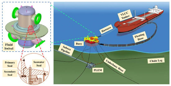
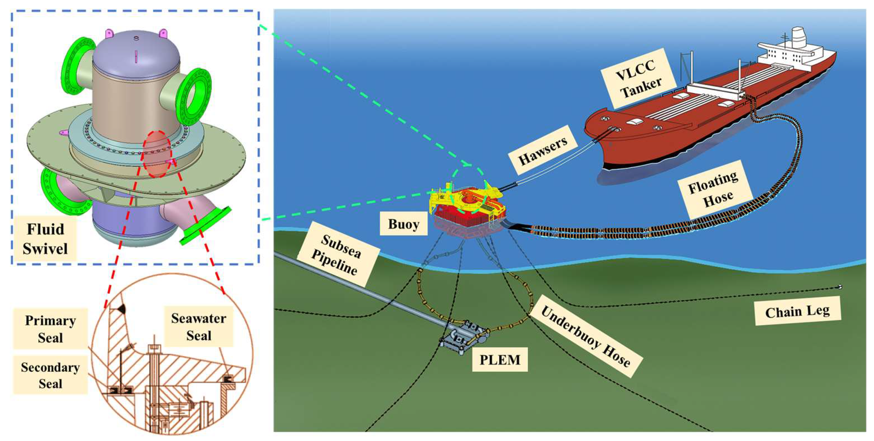
The oil transfer swivel of the catenary single-point mooring system investigated in this study is primarily used for VLCC single-point mooring terminals, as shown in Figure 1. The main technical specifications of the swivel are listed in Table 1. The swivel adopts a single-channel axial rotation configuration and consists of an upper ring (rotating ring), a lower ring (stationary ring), a slewing bearing, and inner and outer seals. The upper and lower rings are connected by a three-row roller slewing bearing capable of withstanding both axial and radial loads. A protective cover is installed around the bearing to prevent water ingress or the entry of foreign objects. The seals at the mating surfaces ensure leak-free fluid transfer between the rotating and stationary rings. The seals are designed to prevent seawater ingress, with one side facing the seawater and the other side facing the internal cavity. As shown in the circled portion of Figure 1, the primary seal and secondary seal prevent seawater from entering the internal chamber while maintaining the integrity of the fluid transfer process.
Figure 1.
Schematic of a spring-energized seal for the fluid swivel in a catenary SPM system.
Table 1.
Main Design Parameters and Technical Specifications of the Swivel System.
The main structure of the swivel employs a rotating end-face seal configuration relative to the crude oil mooring system. Compared with radial sealing, the end-face sealing approach offers several advantages: (1) the grooves are easier to machine, and tolerances on groove depth and geometric form can be effectively controlled, allowing the compression ratio of the seal cross-section to be maintained within an appropriate range and thus ensuring good sealing performance; (2) the groove surfaces can be easily polished, and the surface roughness can meet the required specifications, preventing leakage caused by machining irregularities; and (3) concentricity errors (eccentricity) between the groove and the rotation axis have no adverse effect on end-face sealing.
Given the requirement for a 10-year reliable service life, the seal system must maintain effective sealing even after minor material wear. Considering the groove dimensions provided by the swivel design and the overall reliability requirements, a dual-seal system is adopted for the crude oil swivel, consisting of a primary seal and a secondary seal. Prior to installation, sealing grease is filled in the sealing cavity to provide lubrication between the sealing interfaces. This lubrication reduces friction and wear during long-term operation, thereby enhancing the durability of the sealing system and supporting the requirement for a 10-year service life. The primary seal provides the main sealing function and bears the majority of the fluid pressure. Inevitably, some wear occurs over time. Once the wear exceeds the reliability limit of the primary seal and leakage begins to appear, it acts to relieve pressure and buffer the system. At this stage, the secondary seal becomes active. Since the secondary seal has not been exposed to fluid pressure prior to the failure of the primary seal, its wear is minimal, allowing it to operate effectively for an extended period until the designed service life is reached.
3. Seal Structure Design
3.1. Seal Configuration
Considering the operating conditions of the catenary SPM system, the selected rotating end-face seal is required to possess sufficient elastic compensation capability to ensure long-term effective operation after seal surface wear. Common elastic compensation elements used in seals can be classified into two categories: springs and elastomeric rings, such as O-rings and rectangular rings. Spring-based compensation provides superior recovery capability and sealing performance; however, it is associated with higher costs due to the requirement for spring materials with adequate crude-oil resistance. In contrast, elastomeric rings exhibit limited long-term compensation capability, and their durability is generally insufficient to meet the 10-year service life requirement, although their cost is relatively low. Given the critical role of crude oil sealing and the stringent long-life requirement, spring-energized seals with strong elastic compensation capability are selected as the optimal solution in this study.
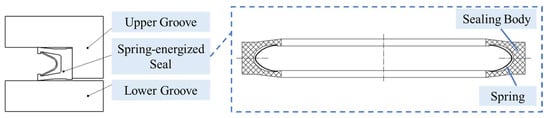
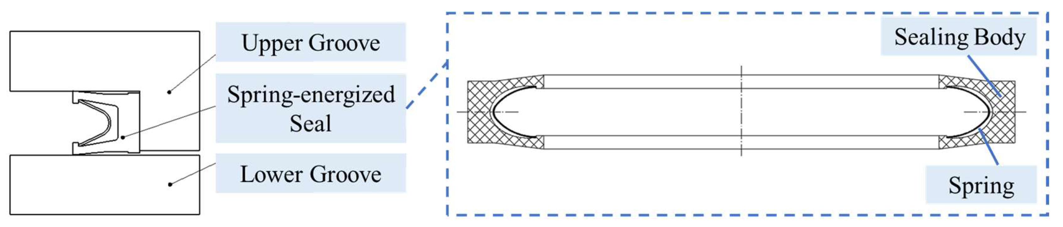
The spring-energized seal designed in this work, as illustrated in Figure 2, consists of a sealing body (Part 1) and a spring element (Part 2). The two end faces of the sealing body are in contact with the mating surfaces of the seal groove. After wear occurs, a continuous elastic compensation force is provided by the spring, ensuring sustained sealing performance. In addition, the spring compensates for seal eccentricity caused by manufacturing and installation tolerances.
Figure 2.
Schematic diagram of the spring-energized seal structure and its installation in the sealing groove.
Based on the sealing medium, operating conditions, and service life requirements, a filled PTFE material is selected for the sealing body. Common spring materials include various stainless steels (e.g., 301, 302, 304, and 316), high-temperature alloys (e.g., Hastelloy and Inconel 718), and spring-wire alloys. In this study, Inconel 718 is adopted to satisfy the crude-oil service requirements, and its chemical composition is listed in Table 2.
Table 2.
Chemical composition of Inconel 718.
The spring-energized end-face seal for the rotating shaft exhibits the following characteristics:
- •
- The sealing body material shows excellent chemical stability and does not react with strong acids, strong alkalis, or strong oxidizing agents, even at elevated temperatures, providing outstanding resistance to crude oil.
- •
- The material exhibits good aging resistance.
- •
- The seal demonstrates favorable manufacturability.
- •
- It possesses good resistance to bending fatigue.
- •
- Owing to its low friction coefficient, the filled PTFE sealing body is well suited for both lubricated and dry operating conditions.
- •
- The metal spring element offers excellent fatigue and corrosion resistance, enabling long-term effective elastic compensation and ensuring sustained sealing performance.
3.2. Sealing Mechanism Analysis
A spring-energized seal belongs to the category of compressed elastomeric seals. The sealing mechanism relies on the elastic deformation induced by the initial compression of the sealing body, which generates a self-energizing force. Meanwhile, the pressure of the working fluid further compresses the sealing body and enhances the self-sealing effect. Under operating conditions, the contact stress Pc between the seal and the sealing end face can be expressed as:
where Pco is the initial contact stress induced by pre-compression of the seal and ∆Pc represents the additional contact stress generated by the crude oil pressure. The latter is related to the lateral pressure coefficient K, given by
where Po is the crude oil pressure inside the fluid swivel and μ denotes the Poisson’s ratio of the sealing body material.
Pc = Pco + ∆Pc
∆Pc = KPo
K = μ/1 − μ
Within the groove, the seal generates contact stress through direct contact with the sealing end faces. Under the applied load, the sealing body undergoes compressive deformation accompanied by lateral expansion, thereby preventing leakage of the crude oil. Accordingly, the sealing performance criterion requires that the peak contact stresses between the spring-energized seal and both sealing end faces exceed the fluid pressure, which can be expressed as:
where Pii = 1, 2 denotes the peak contact pressure on each sealing end face.
Po ≤ min{P1,P2}
During operation, the spring-energized seal is simultaneously subjected to fluid pressure and contact pressure from the sealing end faces. Therefore, the evaluation of sealing performance should not only ensure sufficient contact stress but also guarantee that the equivalent stress in the seal remains below the yield strength of the sealing material, so as to prevent structural failure. This requirement can be written as:
where σmax is the maximum equivalent stress in the seal and σb is the yield strength of the sealing material [31].
σmax < [σb]
3.3. Sealing Structure Design Scheme
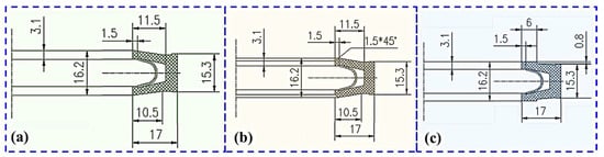
The spring-energized seal is required to maintain reliable sealing performance under a certain pressure level. The outer end face must exhibit sufficient structural stability to avoid lateral overturning, while the inner end face (near the sealing lip) must provide adequate interference to satisfy the sealing requirements. Therefore, the cross-sectional profile of the spring-energized seal is designed to be approximately Y-shaped. In this study, the installation groove of the spring-energized seal is designed with an inner diameter of 1205 mm, an outer diameter of 1245 mm, and a height of 15.3 mm. Three different lip geometries are proposed for the seal design, as illustrated in Figure 3. Scheme I adopts a conventional lip structure, in which the end face near the sealing lip is a tapered surface. Scheme II introduces a large chamfer at the sealing lip. Scheme III employs a flat end face near the sealing lip.
Figure 3.
Three design schemes of the spring-energized seal with different lip geometries. (a) Scheme I: tapered lip; (b) Scheme II: chamfered lip; (c) Scheme III: flat lip.
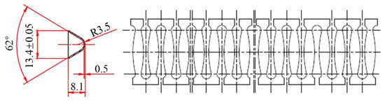
All three schemes employ the same spring, and the cross-sectional geometry of the spring is illustrated in Figure 4. The elastic compensation element (spring) is the core component of the spring-energized seal, and its compensation capability directly determines the sealing performance. Springs used in spring-energized seals are commonly available in circular, elliptical, V-shaped, and U-shaped configurations. However, circular, elliptical, and U-shaped springs provide only a limited compensation range and therefore cannot satisfy the practical requirements of fluid swivels. In contrast, only the V-shaped spring configuration is capable of meeting the required compensation performance.
Figure 4.
Cross-section and unfolded views of the spring compensation element.
To ensure uniform and long-lasting elasticity, the spring is manufactured from strip material. Multiple dumbbell-shaped through-holes are distributed along the spring body. The narrowed middle section of each dumbbell-shaped hole enhances the structural stiffness of the spring, while the enlarged ends improve elastic deformation capability. Each through-hole has only one opening connected to the lateral surface, and the openings at both ends are arranged in a staggered manner. This design ensures structural continuity of the spring and provides superior elastic compensation performance.
4. Finite Element Analysis of the Sealing Structure
4.1. Finite Element Model
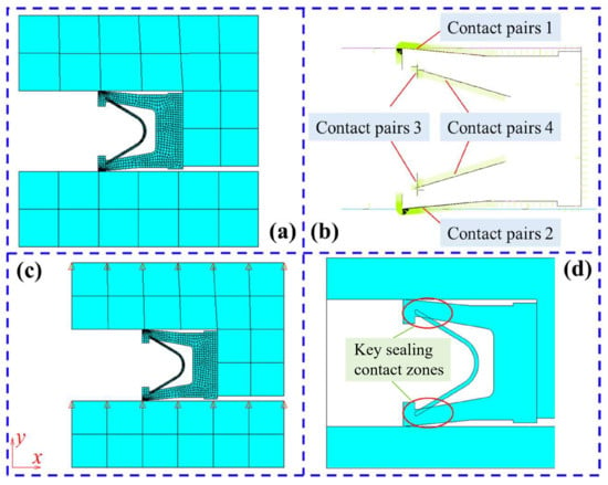
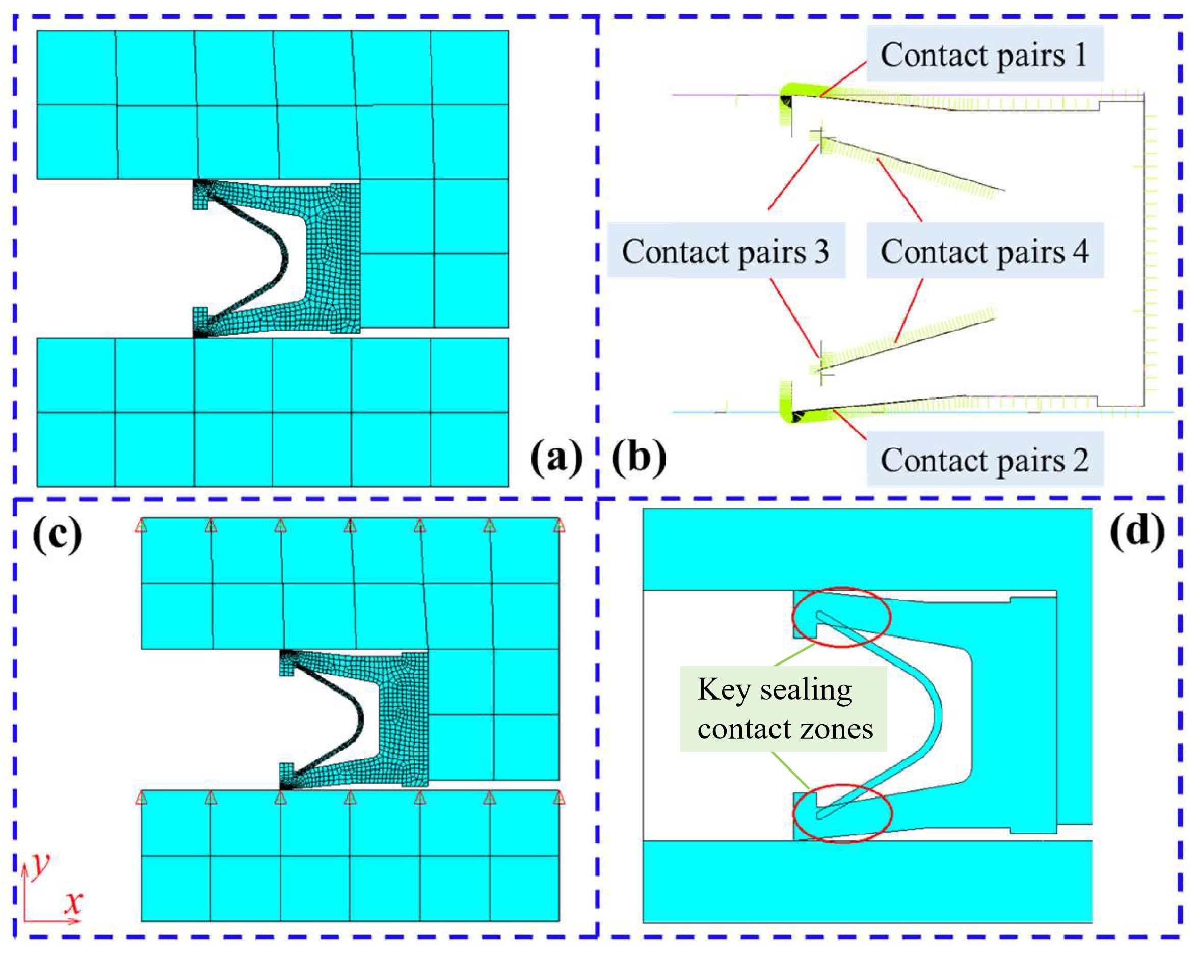
Since the spring-energized seal exhibits circumferential symmetry, and the loading conditions imposed by its installation within the cavity boundary are also circumferentially symmetric, the original three-dimensional solid model of the seal is simplified into a two-dimensional axisymmetric model for the numerical simulation. The finite element model of the spring-energized seal is shown in Figure 5. The geometric model is discretized using the high-order two-dimensional eight-node PLANE183 element. PLANE183 is a quadratic displacement element that is well suited for meshing irregular geometries. Each element consists of eight nodes, with two translational degrees of freedom at each node in the x and y directions. The element can be used for plane stress, plane strain, and generalized plane strain, as well as axisymmetric analyses. To ensure numerical accuracy, a quadrilateral mesh is adopted for the entire model. Local mesh refinement is applied in regions where contact is likely to occur, thereby improving the solution accuracy and enabling a more reliable evaluation of the contact pressure distribution.
Figure 5.
Finite element model of the spring-energized seal. (a) Mesh discretization; (b) Contact pairs; (c) Boundary conditions; (d) Spring geometry model.
In ANSYS, contact interactions are defined using contact pairs, each consisting of a target element and a contact element, which represent the two interacting surfaces. In general, the surface of the rigid body is defined as the target surface, while the surface of the flexible body is defined as the contact surface. The finite element model of the spring-energized seal includes a total of four contact pairs. Contact pair 1 corresponds to the contact between the spring-energized seal and the upper groove, while contact pair 2 represents the contact between the spring-energized seal and the lower groove. Contact pairs 3 and 4 describe the interactions between the sealing body and the spring element. Two contact pairs are employed to properly simulate the spring preloading assembly process, as illustrated in Figure 5b. During actual operation, the spring-energized seal is subjected to compression with a displacement of 0.9 mm. The friction coefficient between the rigid body surface and the seal is set to 0.1. In the numerical model, the displacement of the lower groove in the Y direction is fixed, while a displacement of −0.9 mm is applied to the upper groove in the Y direction to reproduce the compression condition, as shown in Figure 5c.
To evaluate the performance of the spring-energized seal during installation and operation, the finite element analysis is conducted using three sequential load steps. The first load step simulates the spring preloading process of the spring-energized seal. The second load step represents the installation of the seal, while the third load step models the compressed working condition of the spring-energized seal. To ensure an adequate safety margin in the design, a safety factor of 1.5 is adopted in the analysis, corresponding to an internal crude oil pressure of 3 MPa.
During installation, the spring undergoes a pre-compression process when inserted into the sealing body. To accurately capture this behavior, a finite element model of the spring-energized seal in its free (uncompressed) state is established, as shown in Figure 5d. As highlighted in the figure, the spring initially embeds into the sealing body. Therefore, the first load step is applied to eliminate this initial embedding through the preloading procedure, thereby simulating the pre-compressed state of the spring.
The spring-energized seal is composed of two materials: Inconel 718 for the spring element and PTFE for the sealing body. The material properties of both components are listed in Table 3.
Table 3.
Material properties of the spring-energized seal used in the finite element analysis.
4.2. Structural Mechanical Response and Fatigue Life Analysis
4.2.1. Stress and Strain Distribution
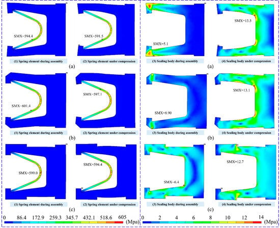
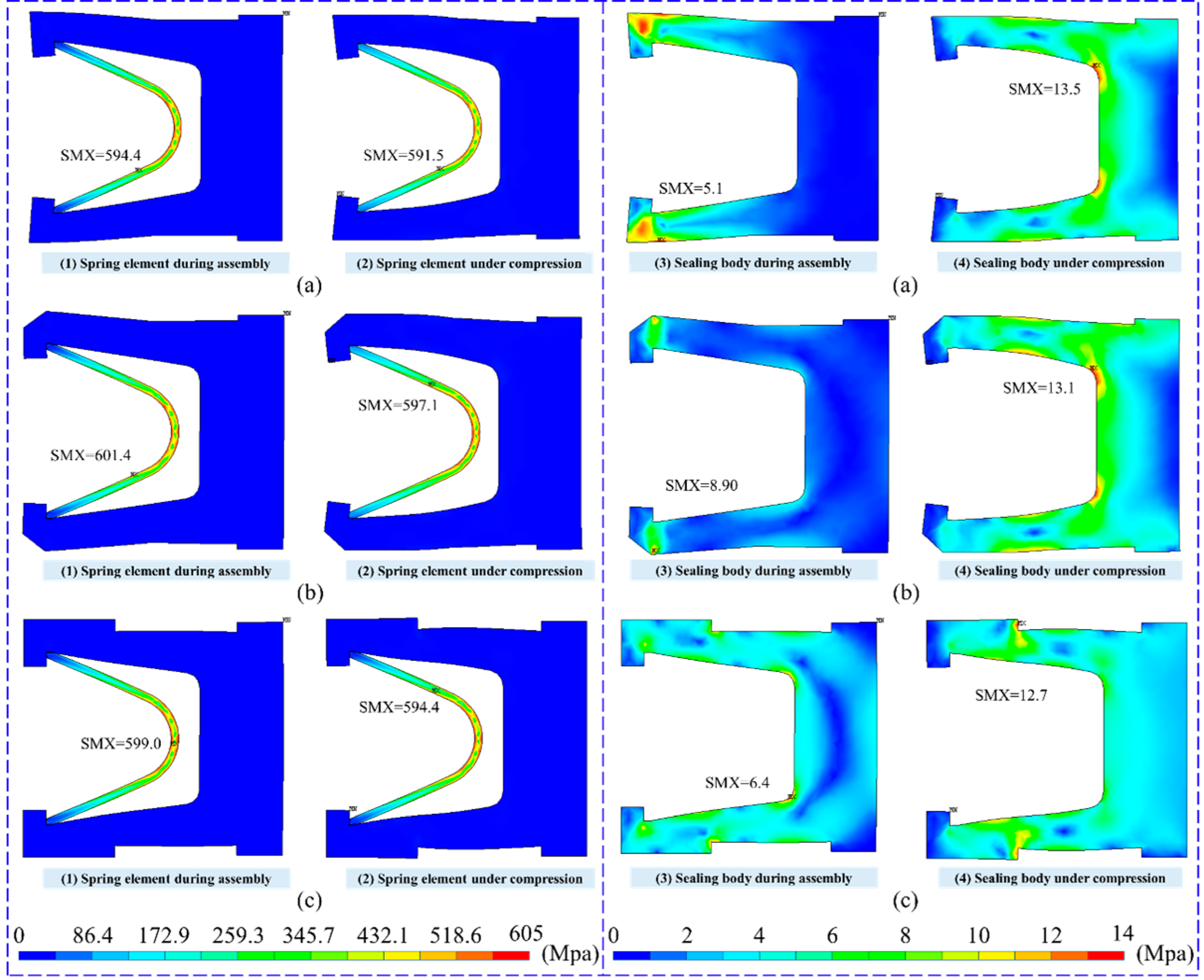
Finite element analysis provides information on the stress, deformation, and contact pressure distribution of the spring-energized seal after assembly, which enables a detailed evaluation of each design scheme. The computed results for the second load step (installation state) and the third load step (compressed working state) are presented separately for each design. Due to the distinct material properties of the sealing body and the spring element, the yield limit of the sealing body is much lower than that of the spring. The spring element is made of metal and can withstand stresses on the order of several hundred MPa, whereas the sealing body is a polymer material with much lower stiffness and yield strength, resulting in stress levels of only several MPa. Due to this large difference in stress magnitude, the equivalent stress distributions of the spring element and the sealing body are presented separately with different color scales. If a unified color scale were applied, the stress variations in the sealing body would be difficult to distinguish because its stress level is much lower than that of the spring element. Therefore, the equivalent stress is reported separately for the sealing body and the spring element.
As shown in Figure 6, for all three design schemes of the spring-energized seal, the maximum stresses in both the spring element and the sealing body remain below their respective yield strengths, indicating that the material selection meets the strength requirements. During assembly, the spring element experiences higher maximum stress than under compressed operation, whereas the sealing body exhibits lower maximum stress during assembly than under compression. For example, in design scheme 2, the maximum stress of the spring element is 601.4 MPa during assembly and 597.1 MPa under compression, while the maximum stress of the sealing body is 8.9 MPa during assembly and 13.1 MPa under compression. The lower stress of the spring element under compression is attributed to the elastoplastic deformation of the sealing body, which leads to migration of the spring contact points and a reduction in the effective lever arm of the spring.
Figure 6.
Equivalent stress distribution of the spring-energized seal under different design schemes. (a) Design scheme 1; (b) Design scheme 2; (c) Design scheme 3.
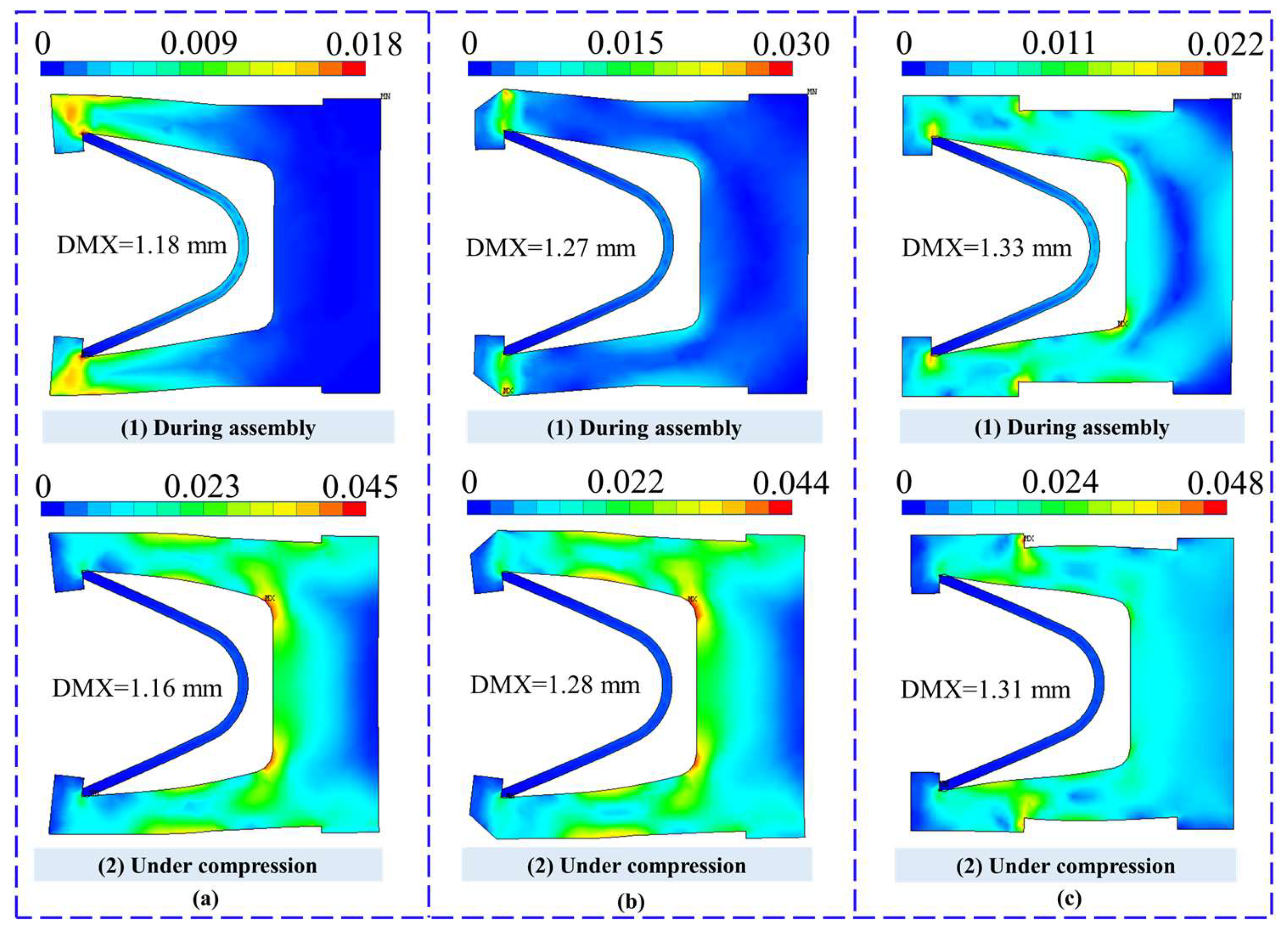
The equivalent strain distribution of the sealing components is presented in Figure 7. For design schemes 1 and 3, the strain under compression is lower than that during assembly, whereas for Design Scheme 2, the strain increases under compression. The maximum displacement under compression is 1.16 mm for Scheme 1 and 1.28 mm and 1.31 mm for Schemes 2 and 3, respectively. In the assembly state, the corresponding maximum displacements are 1.18 mm, 1.27 mm, and 1.33 mm for Schemes 1, 2, and 3, respectively. The locations of the maximum displacements differ among the schemes, which is attributed to the variations in the structural geometry of each design.
Figure 7.
Equivalent strain distribution of the spring-energized seal components. (a) Design scheme 1; (b) Design scheme 2; (c) Design scheme 3.
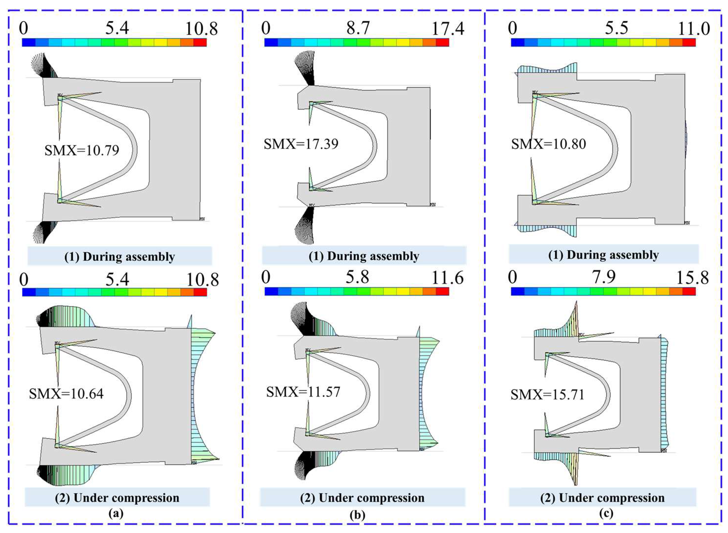
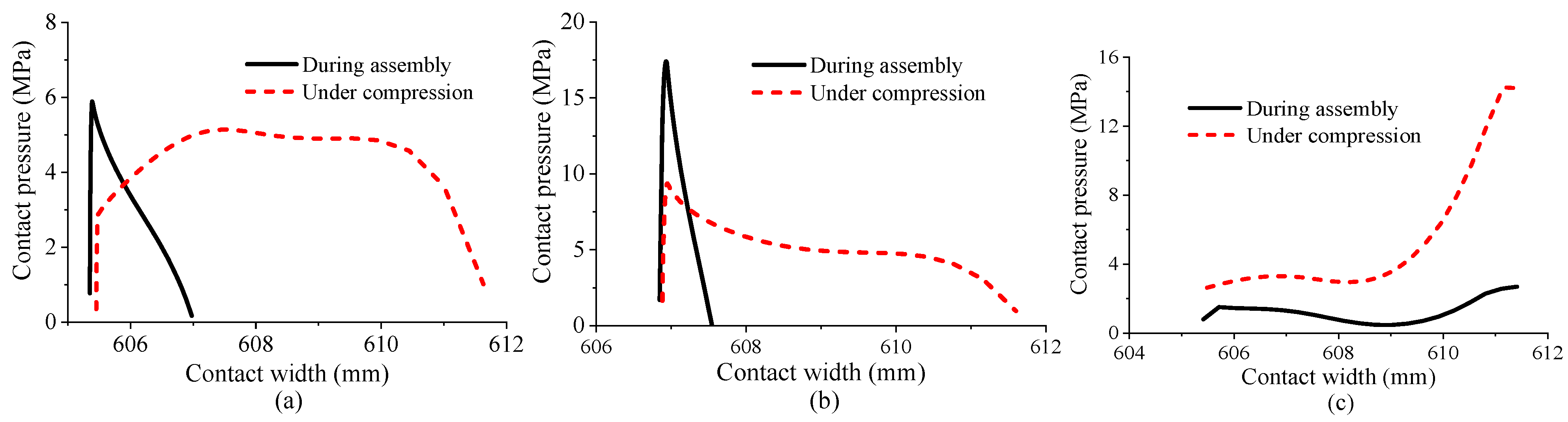
The contact pressure distributions for the three sealing designs are presented in Figure 8. For scheme 1, the maximum contact pressure during assembly is 10.79 MPa, which slightly decreases to 10.64 MPa under internal crude oil pressure. Similarly, for scheme 2, the maximum contact pressure decreases from 17.39 MPa to 11.57 MPa. In both schemes, the sealing width increases under the oil pressure, enhancing sealing reliability. In contrast, scheme 3 exhibits almost no change in sealing width, and the contact pressure increases under oil pressure, indicating that this scheme is not the optimal choice.
Figure 8.
Contact pressure distributions of the spring-energized seal under assembly and internal oil pressure conditions for three design schemes. (a) Design scheme 1; (b) Design scheme 2; (c) Design scheme 3.
4.2.2. Contact Pressure Results
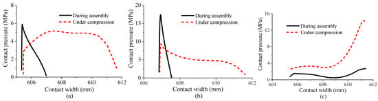
To facilitate a more intuitive comparison of the characteristics of the different design schemes, the contact pressure distributions during assembly and operation are extracted, as shown in Figure 9. In addition, the total pressure applied to the upper groove throughout the analysis is recorded, since the contact pressure distribution directly affects sealing performance, while the total pressure determines the magnitude of frictional forces.
Figure 9.
Contact pressure distributions of the spring-energized seal during assembly and operation for three design schemes. (a) Design scheme 1; (b) Design scheme 2; (c) Design scheme 3.
The extracted results indicate that schemes 1 and 2 are more sensitive to the medium pressure. The maximum contact pressure decreases under the presence of internal pressure, while the contact width significantly increases. For Scheme 1, the contact width expands from 1.7 mm to 6.3 mm, and for scheme 2, it increases from 0.8 mm to 4.8 mm. The increase in contact width elongates the leakage path, making leakage more difficult and improving the sealing performance. It also reduces stress concentration at the lip tip, mitigating local wear. In contrast, scheme 3 is less sensitive to the medium pressure. Its contact width remains nearly 6 mm under pressure, while the maximum contact pressure increases noticeably, which may exacerbate local wear in this region.
4.2.3. Total Pressure Extraction
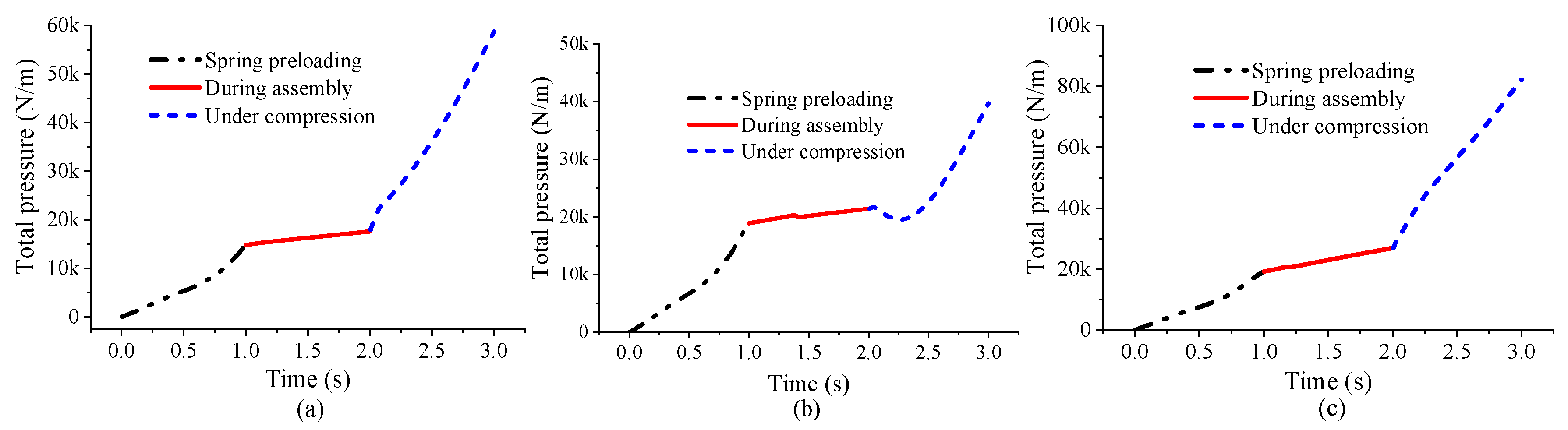
Total pressure refers to the compressive force exerted by the seal, which is required to maintain contact with the end cap. If the total pressure exceeds the end cap clamping force, the end cap may be lifted by the seal, resulting in increased groove clearance and reduced contact pressure. Meanwhile, total pressure can also indirectly reflect the friction force between the seal and the end cap during groove rotation.
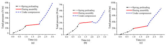
As can be seen from the total pressure extraction results in Figure 10, for all three design schemes, the total pressure continuously increases with spring pre-compression, assembly compression, and operating pressure. This implies that the friction force in all three schemes rises with the increase in spring pre-compression, assembly pre-compression, and working medium pressure. At 3 s of operation, the total pressure reaches 59 N/m for Scheme 1, 39.7 N/m for Scheme 2, and 82.2 N/m for Scheme 3. Notably, the total pressure of Scheme 2 does not increase linearly during operation; it first decreases and then increases, reaching a minimum of 19.7 N/m at 2.3 s, indicating that Scheme 2 is more prone to elastic–plastic deformation.
Figure 10.
Variation in the total pressure of the spring-energized seal during assembly and operation for three design schemes. (a) Design scheme 1; (b) Design scheme 2; (c) Design scheme 3.
4.2.4. Comparative Analysis of Design Schemes
Based on the analysis of equivalent stress, strain, and contact pressure during assembly and pressurization for the three design schemes, the following conclusions are drawn:
- (a)
- In schemes 1 and 2, the sealing interface is located at the lip tip, which allows the spring to effectively compensate for the sealing force. In contrast, in scheme 3, the sealing interface is positioned at the bottom of the flat end face, away from the spring, which limits the effectiveness of spring action.
- (b)
- The applied medium pressure reduces the maximum contact pressure while increasing the contact width in schemes 1 and 2. However, the reduced contact pressure remains significantly higher than the medium pressure, ensuring effective sealing performance. Moreover, the increased contact width extends the leakage path, thereby further hindering medium leakage.
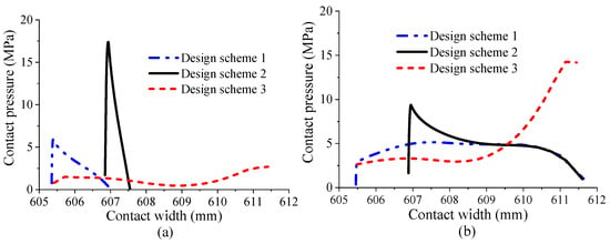
Figure 11 presents a comparison of the contact pressure distributions for the three design schemes. In terms of maximum contact pressure, during assembly, scheme 2 exhibits the highest value of 17.4 MPa, followed by scheme 1 at 5.7 MPa, while scheme 3 shows the lowest value of 2.7 MPa. After applying a medium pressure of 3 MPa, the maximum contact pressure decreases in the order of scheme 3 (14.3 MPa), scheme 2 (9.4 MPa), and scheme 1 (5.1 MPa). With respect to contact width, scheme 3 shows the largest contact width during assembly, followed by scheme 1, whereas scheme 2 exhibits the smallest. After pressurization to 3 MPa, the contact width decreases in the order of scheme 1, scheme 3, and scheme 2.
Figure 11.
Comparison of contact pressure distributions of the spring-energized seal for three design schemes. (a) During assembly; (b) Under compression.
Although the maximum contact pressures of all three schemes remain significantly higher than the applied medium pressure during operation, ensuring effective sealing performance, excessively high contact pressure tends to accelerate seal wear. Therefore, a lower contact pressure is preferable provided that sealing requirements are satisfied. Moreover, a larger contact width implies a longer leakage path for crude oil, thereby reducing the likelihood of leakage. Based on the calculated contact pressure distributions, scheme 1 is considered the most favorable design.
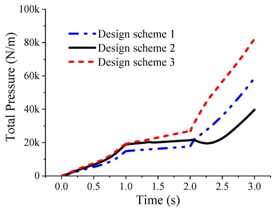
Figure 12 presents the calculated total pressure for the three design schemes. The results show that scheme 3 exhibits a significantly higher total pressure than schemes 1 and 2. At low medium pressures, the total pressure of scheme 1 is lower than that of scheme 2. However, as the medium pressure increases, the growth rate of total pressure in scheme 1 exceeds that in scheme 2, and when the medium pressure reaches 3 MPa, the total pressure of Scheme 1 becomes higher than that of scheme 2. Consequently, scheme 1 yields the lowest friction force at low medium pressures, whereas scheme 2 provides the lowest friction force at higher medium pressures.
Figure 12.
Comparison of total pressure of the spring-energized seal for three design schemes under different medium pressures.
In summary, among the three design schemes, scheme 1 exhibits lower equivalent strain, a more favorable contact pressure distribution, a larger contact width, and lower friction force, making it the optimal design. Scheme 2 ranks second in overall performance. In contrast, scheme 3 shows the highest maximum contact pressure, which is prone to inducing localized wear. Moreover, after assembly, the contact pressure at the lip region of scheme 3 is nearly zero, making it susceptible to lip lifting under pressurization. In addition, its relatively high total pressure requires a larger end-cap clamping force and results in higher friction, rendering scheme 3 the least favorable design among the three.
4.3. Fatigue Life Analysis
Under the action of crude oil pressure, the relative position between the rotating ring and the stationary ring of the rotary joint changes, leading to a variation in the depth of the sealing groove within a range of 15.3~15.7 mm. As a result, the spring-energized seal is subjected to cyclic loading. Therefore, a fatigue life analysis of the spring-energized seal is conducted to evaluate whether it can satisfy the fatigue life requirement over a service period of 10 years.
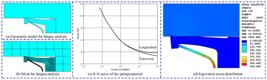
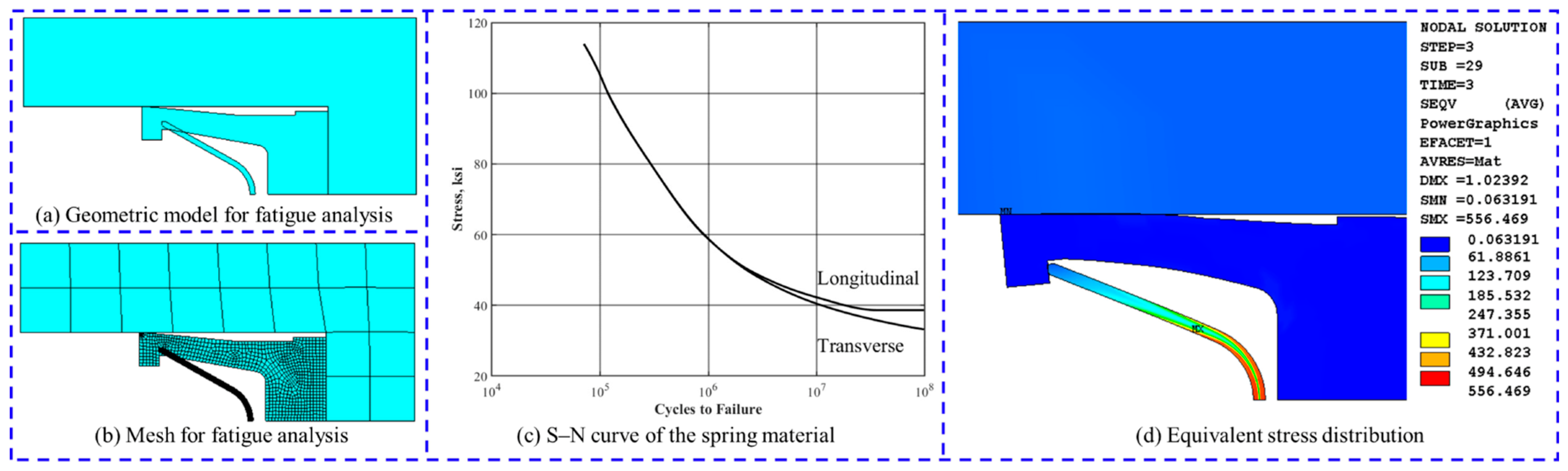
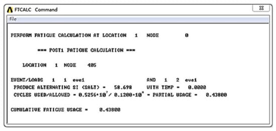
Considering the cross-sectional symmetry of the spring-energized seal, a symmetric model is further established based on the axisymmetric model to reduce computational cost and improve efficiency. The analysis model is illustrated in Figure 13a. Since the fatigue life of the spring is of primary concern, mesh refinement is applied to the spring model, and the meshing results are shown in Figure 13b. The spring is made of Inconel 718, and its S–N fatigue curve is shown in Figure 13c.
Figure 13.
Fatigue life analysis of the spring-energized seal under a working pressure of 3 MPa.
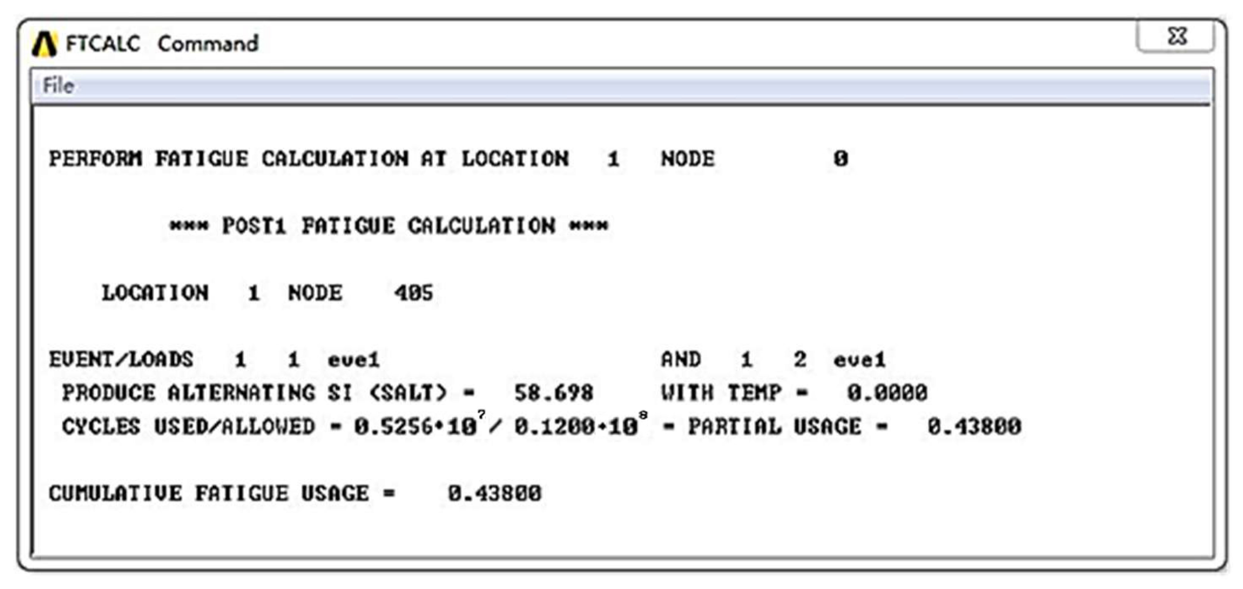
Regions with higher stress are more susceptible to fatigue failure. The equivalent stress distribution of the spring-energized seal under a working pressure of 3 MPa is shown in Figure 13d, where stress concentration occurs near the bottom of the spring groove. The node corresponding to the maximum stress is identified using command flow and selected as the critical location for fatigue analysis. According to the actual operating conditions, the mooring system rotates once per minute on average, with a designed service life of 10 years. Therefore, the spring-energized seal is subjected to a total of 5,256,000 loading cycles, which defines the fatigue life requirement under a medium pressure of 3 MPa. Fatigue calculations are performed using the fatigue module in ANSYS with the corresponding parameters, and the fatigue life result at the critical location is shown in Figure 14. The results indicate that, under the considered loading condition, the usage factor corresponding to the required 5,256,000 cycles is 0.438, demonstrating that the fatigue life requirement is satisfied.
Figure 14.
Fatigue analysis results.
5. Conclusions
This study focuses on the long-life dynamic sealing performance of a fluid rotary joint used in single-point mooring systems. A spring-energized seal is designed with a PTFE-based composite material as the sealing jacket and Inconel 718 as the spring material. A dumbbell-shaped spring configuration is adopted. Reliability-oriented finite element analysis and life prediction of the seal are carried out using ANSYS. The main findings are summarized as follows:
- (1)
- A finite element analysis method for evaluating the performance of spring-energized seals is developed. A numerical model of the spring-energized seal is established to simulate its mechanical behavior under spring preloading, assembly, and pressure loading conditions. The stress–strain responses and contact pressure distributions of the seal under different states are obtained. The results show that the maximum stresses in both the spring and the sealing jacket remain below their respective yield strengths, indicating that the selected materials satisfy the strength requirements.
- (2)
- Based on the proposed finite element analysis method, three seal design schemes are modeled and evaluated under various operating conditions. Equivalent strain, maximum contact pressure, and contact width are adopted as key performance indicators. Comparative analysis demonstrates that Scheme 1 exhibits lower equivalent strain, a more favorable contact pressure distribution, a larger contact width, and lower friction force, making it the most suitable design among the three schemes.
- (3)
- A fatigue life assessment is performed for the optimized design (scheme 1). A fatigue life prediction model of the spring-energized seal is established using ANSYS. The analysis results show that, over a service life of 10 years, the usage factor at the location of maximum stress is 0.438, indicating that the seal meets the fatigue life requirement.
The proposed sealing technology for fluid rotary joints in single-point mooring systems effectively addresses the issues of poor sealing performance and short service life commonly encountered in existing rotary face seal products. As a large-scale seal design technology applicable to complex operating conditions, the present work provides valuable guidance for the dynamic seal design of similar offshore engineering equipment. However, the potential influences of thermal effects, progressive wear, and harsh marine environmental conditions on long-term sealing stability still require further systematic investigation. Nevertheless, further investigations under real sea-state conditions are required to validate the sealing performance, which will provide a solid foundation for future technological breakthroughs of spring-energized seals.
Author Contributions
C.L.: Writing—Original Draft, Formal Analysis; X.F.: Writing—Original Draft, Funding Acquisition; Z.L. (Zhilin Liu): Software, Methodology; S.Y.: Investigation, Project Administration, Funding Acquisition; Y.Z.: Writing—Review & Editing, Visualization; C.T.: Conceptualization, Resources; Z.L. (Zhiran Lu): Validation; Z.H.: Data Curation, Investigation; H.C.: Software, Validation; H.S.: Data Curation, Conceptualization; Y.H.: Writing—Review & Editing. All authors have read and agreed to the published version of the manuscript.
Funding
This research was funded by the National Natural Science Foundation of China (Grant number: 42476225 & 42506217 & 52471320), Guangdong Provincial Government Procurement Project of China (Grant No. GPCGD252200FG178F), and the Jimei University Young Top Talent Program (Class A) (Grant No. ZQ2024114).
Data Availability Statement
The data that support the findings of this study are available from the corresponding author upon reasonable request. The data are not publicly available due to privacy.
Conflicts of Interest
Author Xianjin Fang was employed by Guangzhou Marine Engineering Corporation. Author Zehua Hu was employed by Guangzhou Mechanical Engineering Research Institute Co., Ltd. The remaining authors declare that the research was conducted in the absence of any commercial or financial relationships that could be construed as a potential conflict of interest.
References
- Murdjito Silfiani, M.E.; Syalsabila, F.; Sujantoko Frestiqauli, S.; Djatmiko, E.B. Effect of triangle plate positioning on mooring line tension of single point mooring system. In IOP Conference Series: Earth and Environmental Science; IOP Publishing: Bristol, UK, 2025; Volume 1461, p. 012032. [Google Scholar]
- Bernitsas, M.M.; Papoulias, F.A. Stability of single point mooring systems. Appl. Ocean Res. 1986, 8, 49–58. [Google Scholar] [CrossRef] [Scilit]
- Fan, J.; Bai, H.; Wang, M.; Fang, H. Research on cable dynamic response of a catenary anchor leg mooring system based on ANCF. Ocean Eng. 2024, 305, 117916. [Google Scholar] [CrossRef] [Scilit]
- Olsen, A.A. Mooring System Components. In Position and Nearshore Mooring: Class Theory and Practice; Springer Nature: Cham, Switzerland, 2024; pp. 49–60. [Google Scholar] [CrossRef] [Scilit]
- Chen, B.; Huang, Z. Design of an External Turret Single Point Mooring System for Aquaculture Support Vessels. In 2024 International Conference on Intelligent Ships and Electromechanical System (ICISES); IEEE: New York, NY, USA, 2024; pp. 28–31. [Google Scholar]
- Ju, X.; Dong, B.; Meng, X.; Yin, C.; Li, C.; Xu, Z.; Li, C.; Yang, S.; Chen, H.; Luan, Y.; et al. A Fixed Single-Point Mooring Innovation Solution for Offshore LNG-FSRU Import Terminal. In Abu Dhabi International Petroleum Exhibition and Conference; SPE: Richardson, TX, USA, 2024; p. D041S157R006. [Google Scholar]
- Housner, S.; Sirnivas, S. PacWave Anchoring and Mooring Study; National Renewable Energy Laboratory (NREL): Golden, CO, USA, 2023.
- Zeng, W.; Ma, Y.; Sun, L. Response of a Soft Yoke Mooring System Under Extreme Waves with Double-Peak Spectra. In ISOPE International Ocean and Polar Engineering Conference; ISOPE: Mountain View, CA, USA, 2025; p. ISOPE-I-25-349. [Google Scholar]
- Tang, Y. Soft YOKE Single Point Mooring System. In Encyclopedia of Ocean Engineering; Springer Nature: Singapore, 2022; pp. 1752–1757. [Google Scholar]
- Minnebo, J.; Duggal, A.; Kumar, K. Applied Condition Monitoring and Digitalization of Turret Mooring Systems. In Proceedings of the Offshore Technology Conference (OTC), Houston, TX, USA, 2–5 May 2022; p. D011S011R005. [Google Scholar]
- Wichers, J. Guide to Single Point Moorings. WMooring. 2013. Available online: https://www.scribd.com/doc/250882816/Guide-to-Single-Point-Moorings (accessed on 10 March 2026).
- Eghbali, B.; Daghigh, M.; Daghigh, Y.; Azarsina, F. Mooring line reliability analysis of single point mooring (SPM) system under extreme wave and current conditions. Int. J. Marit. Technol. 2018, 9, 41–49. [Google Scholar] [CrossRef] [Scilit]
- Ji, Z.; Lei, J.; Chen, W.; Dong, B.; Liu, B. Research on the Design of King Post Style Single Point Mooring System. In ISOPE International Ocean and Polar Engineering Conference; ISOPE: Mountain View, CA, USA, 2024; p. ISOPE-I-24-034. [Google Scholar]
- Li, P.; Jin, C.; Ma, G.; Yang, J.; Sun, L. Evaluation of dynamic tensions of single point mooring system under random waves with artificial neural network. J. Mar. Sci. Eng. 2022, 10, 666. [Google Scholar] [CrossRef] [Scilit]
- Lv, W.; Deng, C.; Lin, W.; Gao, Q.; Wang, S.; Han, G. Leakage Verification and Analysis of the Fluid Swivel of the Single-Point Mooring System. In 2024 5th International Conference on Mechatronics Technology and Intelligent Manufacturing (ICMTIM); IEEE: New York, NY, USA, 2024; pp. 708–714. [Google Scholar]
- Xin, S.; Wang, Y.; Lu, W.; Xiong, H. Analysis on Key Technology of Product Swivel for Single Point Mooring. China Offshore Plaform 2023, 38, 92–96. [Google Scholar] [CrossRef]
- Huai, L.; Li, C. Structural Design and Analysis of Oil Swivel Device For the Single Point Mooring. China Pet. Mach. 2019, 47, 91–95+124. [Google Scholar] [CrossRef]
- Jian, Y.; Shun, X.I.N.; Yi, W. Structure design of fluid swivel for single point mooring system based on simulation analysis. Dev. Appl. Mater. 2022, 37, 49–53. [Google Scholar] [CrossRef]
- Zhang, Z.; An, C.; Yu, J.; Wei, D.F. Numerical simulation on the erosion damage of liquid swivel in a single point mooring system. J. Appl. Sci. Technol. 2022, 49, 43–50. [Google Scholar] [CrossRef] [Scilit]
- Mao, J.; Liu, H.; Wang, H. Challenges and Solutions of” FPSO+ Subsea” Mode Development for South China Sea. In ISOPE International Ocean and Polar Engineering Conference; ISOPE: Mountain View, CA, USA, 2022; p. ISOPE-I-22-085. [Google Scholar]
- Liu, D.; Zhao, J.; Li, S.; Zhao, X.; Huang, L. Experimental study on tribological and leakage characteristics of a rotating spring-energized seal under high and low temperature. Machines 2023, 11, 221. [Google Scholar] [CrossRef] [Scilit]
- Wang, H.; Zhang, D.; Cheng, J.; Xin, S.; Gao, H.; Liu, L. Analysis of In-Situ Operating Load Conditions of Swivel Stack in Inner Turret SPM System of FPSO. In International Workshop of Advanced Manufacturing and Automation; Springer Nature: Singapore, 2024; pp. 349–356. [Google Scholar]
- Keegan, J. The Design of an Experimental Testing Fixture to Test Seals of Various Geometries Exposed to Extreme Operational Conditions While Operating in Dynamic Rectilinear Motion. 2023. Available online: https://shareok.org/handle/11244/337490 (accessed on 9 March 2026).
- Flenniken, A. The Design and Adaptation of an Experimental Test Setup to Characterize Metal Spring Energized Seals. 2023. Available online: https://shareok.org/handle/11244/337952 (accessed on 5 March 2026).
- Zhang, F.; Xiang, C.; Guo, F.; Zheng, M.; Jia, X. An equivalent axisymmetric modeling approach for circumferential springs under large deformation based on mechanical anisotropy. Proc. Inst. Mech. Eng. Part C J. Mech. Eng. Sci. 2024, 238, 8376–8389. [Google Scholar] [CrossRef] [Scilit]
- Huang, T.C.; Tsai, J.W.; Liao, K.C. Wear and leakage assessments of canted coil Spring–Energized polytetrafluoroethylene seals under Ultra-High cycle operations. Eng. Fail. Anal. 2022, 135, 106110. [Google Scholar] [CrossRef] [Scilit]
- Zhao, Y.; Yu, J.; Huang, L. Analysis of the sealing characteristics of spring energized seal ring under high-pressure environments. Lubr. Eng. 2023, 48, 143–148. [Google Scholar] [CrossRef]
- Gao, H.Y.; Li, J.J.; Du, B.; Li, L.L.; Sun, J.B.; Yue, Q.J. Research on sealing performance of single point mooring liquid swivel seal ring. Lubr. Eng. 2019, 44, 75–80. [Google Scholar] [CrossRef]
- Hu, Z. Structural Optimization of a Spring Accumulator Seal of Rotating Shaft End-face. Lubr. Eng. 2016, 41, 122–124. [Google Scholar] [CrossRef]
- Sun, Q.; Li, W.; Li, R.; Peng, D.; Guo, Q.; Zhao, Y.; Yue, Q.; Zhong, W. Anchor chain optimization design of a catenary anchor leg mooring system based on adaptive sampling. J. Mar. Sci. Eng. 2022, 10, 1739. [Google Scholar] [CrossRef] [Scilit]
- Zhang, S. Design and Simulation of Soft Yoke Mooring System. Master’s Thesis, Yanshan University, Qinhuangdao, China, 2024; pp. 69–73. [Google Scholar] [CrossRef]

Disclaimer/Publisher’s Note: The statements, opinions and data contained in all publications are solely those of the individual author(s) and contributor(s) and not of MDPI and/or the editor(s). MDPI and/or the editor(s) disclaim responsibility for any injury to people or property resulting from any ideas, methods, instructions or products referred to in the content. |
© 2026 by the authors. Licensee MDPI, Basel, Switzerland. This article is an open access article distributed under the terms and conditions of the Creative Commons Attribution (CC BY) license.