


Abstract
The water-lubricated piston–cylinder pair is a critical tribological component in hydraulic systems, yet its performance under boundary lubrication is often limited by high friction and severe wear. Conventional epoxy coatings provide only modest improvements. In this study, graphene-modified epoxy composite coatings were developed and applied to piston substrates, then characterized via scanning electron microscopy, white light interferometry, and nanoindentation. Tribological performance was evaluated using a reciprocating tribometer under simulated pump conditions of 16 MPa and 1500 r/min. Compared to the pure epoxy coating, the graphene-modified coating reduced the friction coefficient by 33.9% and the wear rate by 77.2%, while the graphene oxide-modified coating reduced them by 16.1% and 64.5%, respectively. These results demonstrate that graphene-modified epoxy composite coatings offer an effective surface engineering solution for enhancing the durability and efficiency of water-lubricated systems, with promising potential for water hydraulic applications.
1. Introduction
As the core power component of modern hydraulic transmission systems, the water-lubricated radial piston pump is widely recognized as the “heart” of fully mechanized mining equipment, playing an indispensable role in numerous industrial fields such as coal mining machinery, marine engineering, food processing, and metallurgical equipment [1]. Compared with traditional oil-based systems, water hydraulic transmission technology using filtered fresh water or seawater as the working medium offers significant advantages, including environmental friendliness, high safety, and low cost, and has thus become a key direction in the development of green hydraulic technology [2]. As one of the most numerous and critical friction pairs in a radial piston pump, the piston–cylinder pair directly determines the volumetric efficiency and service life of the pump [3]. However, the dynamic viscosity of water is only 1/30 to 1/50 that of mineral oil, posing severe technical challenges for the piston–cylinder pair under water-lubricated conditions [4]. The low viscosity of water makes it difficult to form a stable and continuous lubricating film at the friction interface, rendering the piston and cylinder bore prone to boundary lubrication or even dry friction [5], which leads to a significant increase in wear rate and may result in severe consequences such as piston seizure, high-pressure leakage, and seal failure [6,7,8]. In addition, the water medium can exacerbate electrochemical corrosion of the friction pair materials [9]. Consequently, the friction and wear issues of the piston–cylinder pair have become a critical technical bottleneck restricting the development of water-lubricated radial piston pumps toward high pressure, high efficiency, and high reliability [10].
In 2004, E. Peter et al. [11] modified a commercial alumina ceramic and an alumina–zirconia ceramic (ZTA) by laser cladding to improve the tribological performance under mixed lubrication conditions in reciprocating sliding contacts with media lubrication, such as those encountered in sealed piston pumps. Unlubricated and media-lubricated tests conducted in a ring-on-disc laboratory tribometer demonstrated that pairings of edge-layer modified ceramics exhibited significantly higher wear resistance than those of commercial ceramics. In 2016, Wu et al. [12] investigated the tribological characteristics of Al2O3–TiO2 coatings with varying TiO2 contents combined with Si3N4 ceramics under sand-containing water and tap water lubrication conditions using a ring-on-ring friction and wear tester. The results indicated that the Al2O3–13%TiO2 coating was the preferred choice for the friction pair with Si3N4 in water hydraulic pumps. In 2019, Nie et al. [13] employed a pin-on-pin friction and wear tester to study the friction and wear behavior of 17-4PH stainless steel and 17-4PH stainless steel coated with Cr3C2–NiCr, WC–10Co–4Cr, Cr2O3, and Al2O3–13%TiO2 against carbon fiber-reinforced polyetheretherketone (CF-PEEK) composites under water-lubricated conditions, aiming to improve the wear resistance of key friction pairs in water hydraulic piston pumps. In 2023, Li et al. [14] investigated the tribological properties of CF-PEEK against 316L and 1Cr17Ni2 under water-lubricated conditions, demonstrating that enhancing the wear resistance of metals is crucial for the development of water-lubricated piston pumps. Li Ran et al. [15] conducted friction and wear tests on five copper-based materials and three PEEK-based composites using two types of cylinder-on-disc specimens to represent the sliding/eccentric drive and piston/sleeve clearance seal tribopairs in water hydraulic radial piston pumps. The wear mechanisms of these two tribopairs were characterized by scanning electron microscopy, profilometry, and energy-dispersive spectroscopy. In 2024, Li et al. [16] investigated the tribological behavior of the slipper/eccentric cam friction pair at the power end of a water hydraulic radial piston pump under different lubrication conditions. In 2025, Liang et al. [17] designed a multilevel composite texture inspired by natural biological surface structures to reduce the wear of the slipper in seawater hydraulic axial piston pumps. Friction and wear experiments were conducted using CF/PEEK and 316L stainless steel, and the tribological characteristics of different surface textures were analyzed. In 2026, Liang et al. [18] analyzed the friction coefficient, temperature, and wear rate through friction and wear tests of 431 stainless steel against CF/PEEK. The NSGA-II algorithm was employed for multi-objective optimization of key texture parameters, and the optimization results showed that the hexagonal texture exhibited the best performance, reducing the friction coefficient by 32%, while the aspect ratio significantly influenced the load-carrying and friction-reducing properties of the water film.
Surface engineering techniques have emerged as an effective approach to enhance the service performance of tribological components [19], among which organic coatings have garnered significant attention due to their excellent friction-reducing properties, good conformability, and straightforward preparation processes. Polymer-based coatings can form a transfer film at the friction interface, effectively preventing direct contact between metal substrates and thereby reducing both the friction coefficient and wear rate [20]. Although engineering plastics such as polytetrafluoroethylene (PTFE) and polyetheretherketone (PEEK) have achieved certain friction-reducing effects [21,22], their limited mechanical strength and inadequate adhesion restrict their widespread application in high-pressure piston pumps [23]. Epoxy resin, widely used in metal protection due to its excellent adhesion, mechanical strength, and film-forming ability [24], exhibits inherent limitations such as high crosslinking density and brittleness, which render it prone to wear debris and microcracking under alternating loads [25]; moreover, its limited self-lubricating properties result in a high friction coefficient and restricted wear life under water-lubricated conditions [26], making it difficult to meet the demands of long-term reliable operation. Therefore, the modification of epoxy resin with nanofillers has been pursued to enhance its comprehensive tribological performance [27]. Graphene, with its unique two-dimensional layered structure, exceptional mechanical properties, and excellent self-lubricating characteristics [28], can form a physical barrier within the epoxy matrix, effectively transferring load and inhibiting crack propagation [29]; concurrently, it can be exfoliated and transferred to the interface during friction, forming a low-shear lubricating film that significantly reduces the friction coefficient [30].
Numerous studies have confirmed the excellent performance of graphene-modified epoxy coatings under dry friction and oil-lubricated conditions. In 2013, Shen et al. [31] investigated the tribological properties of graphene oxide (GO)/epoxy nanocomposites; friction and wear tests against smooth steel substrates revealed that at a GO content of 0.5 wt%, the specific wear rate decreased by 90.0–94.1% compared with that of pure epoxy, demonstrating the significant advantages of using GO in improving the wear resistance of epoxy resins. In 2015, Duzcukoglu et al. [32] studied the friction and tribological behavior of epoxy resins modified with multi-walled carbon nanotubes (MWCNTs) and boron nitride (BN), and compared the results with those of pure epoxy; it was observed that nanoparticle modification improved wear resistance and reduced both the friction coefficient and operating temperature. Xu et al. [33] investigated the preparation of superhydrophobic polymer coatings by spraying and dip-coating methods, discussed the feasibility of the two techniques for large-scale coating fabrication, and demonstrated that both spraying and dip-coating could effectively form uniform coatings on various substrates, making them suitable for large-area industrial applications. In 2021, Alessia Serena Perna et al. [34] conducted nanoindentation tests on carbon fiber- and glass fiber-reinforced polypropylene composite coatings deposited on steel and aluminum substrates by cold spraying, and discussed the effects of fibers and spraying powders on coating properties. Bao et al. [35] used polyether amine-functionalized graphene oxide to prepare epoxy composites and investigated the mechanical, thermal, and tribological properties of composites with different types and contents of fillers; compared with the neat resin, the polyether amine-functionalized GO/epoxy composite with a filler content of 0.2 wt% exhibited optimal tribological performance, thermal stability, and mechanical properties. Zhao et al. [36] utilized modified graphene and polytetrafluoroethylene (PTFE) to improve the tribological properties of epoxy coatings. Modified graphene (RGO-EDA) was obtained by reducing graphene oxide with dehydrated ethylenediamine to enhance its dispersion in epoxy and the interfacial bonding between graphene and the epoxy matrix. RGO-PTFE/EP composite coatings were prepared by adding different concentrations of RGO-EDA to epoxy resin, and tribological experiments were conducted. Tribological tests showed that the friction coefficient and wear rate of the epoxy coating were significantly reduced after the addition of RGO-EDA and PTFE. In 2022, Xia et al. [37] employed carbon spheres coated with dispersed graphene (graphene spheres, g-AM) as fillers to prepare epoxy composites via direct mixing and curing methods. Compared with the neat cured epoxy, the E-g-AM/EP composite exhibited a 95% reduction in wear rate at an E-g-AM content of 20 wt%. This excellent wear resistance was attributed to the synergistic effect of the carbon spheres and graphene, where the carbon spheres enhanced the Shore hardness and flexural strength, thereby reducing the wear rate. In 2024, Hao et al. [38] incorporated graphene oxide (G) into epoxy resin and comprehensively analyzed the structural differences and similarities of G (GO), the latest preparation methods, and their interrelationships, aiming to enhance the flame retardancy, mechanical properties, corrosion resistance, thermal properties, wear resistance, and electrical properties of GO-modified epoxy composites.
In summary, existing studies have focused on incorporating various types of nanomaterials into epoxy coatings to leverage the excellent self-lubricating properties of the fillers, thereby effectively reducing the friction coefficient and improving wear resistance. However, these investigations have primarily concentrated on coating performance improvements under dry friction or oil-lubricated conditions, as well as the preparation of coatings on planar substrates. Systematic research on the tribological behavior of graphene/epoxy composite coatings under water-lubricated conditions remains relatively limited, and studies on the coating preparation process for shaft component surfaces are insufficient. Therefore, in this study, epoxy composite coatings with different graphene contents were fabricated in consideration of the actual operating conditions of piston pumps, such as high-pressure alternating loads and reciprocating motion modes. The tribological properties were systematically investigated under simulated reciprocating motion and water-lubricated conditions, the lubrication mechanism was elucidated, and the preparation process was optimized. Combined with microstructural characterization, the tribological mechanisms were analyzed. This study aims to provide an effective technical solution for the surface protection of water-lubricated piston–cylinder pairs, which holds significant theoretical value and practical importance for promoting the engineering application of high-performance water-lubricated hydraulic components. Therefore, the innovation of this study lies in the systematic evaluation of the tribological performance of epoxy coatings modified with varying contents of graphene and graphene oxide under water-lubricated conditions using laboratory-scale tests that incorporate actual operating parameters, followed by validation of the coating feasibility under realistic working conditions through single-piston pump experiments.
2. Materials and Methods
2.1. Research Object and Tribological Issues
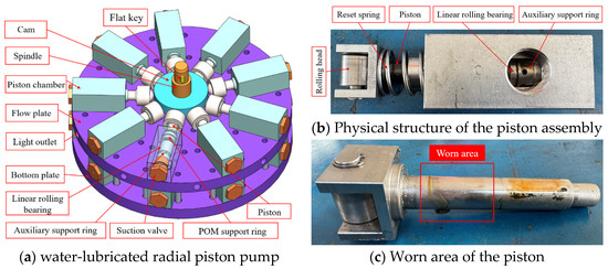
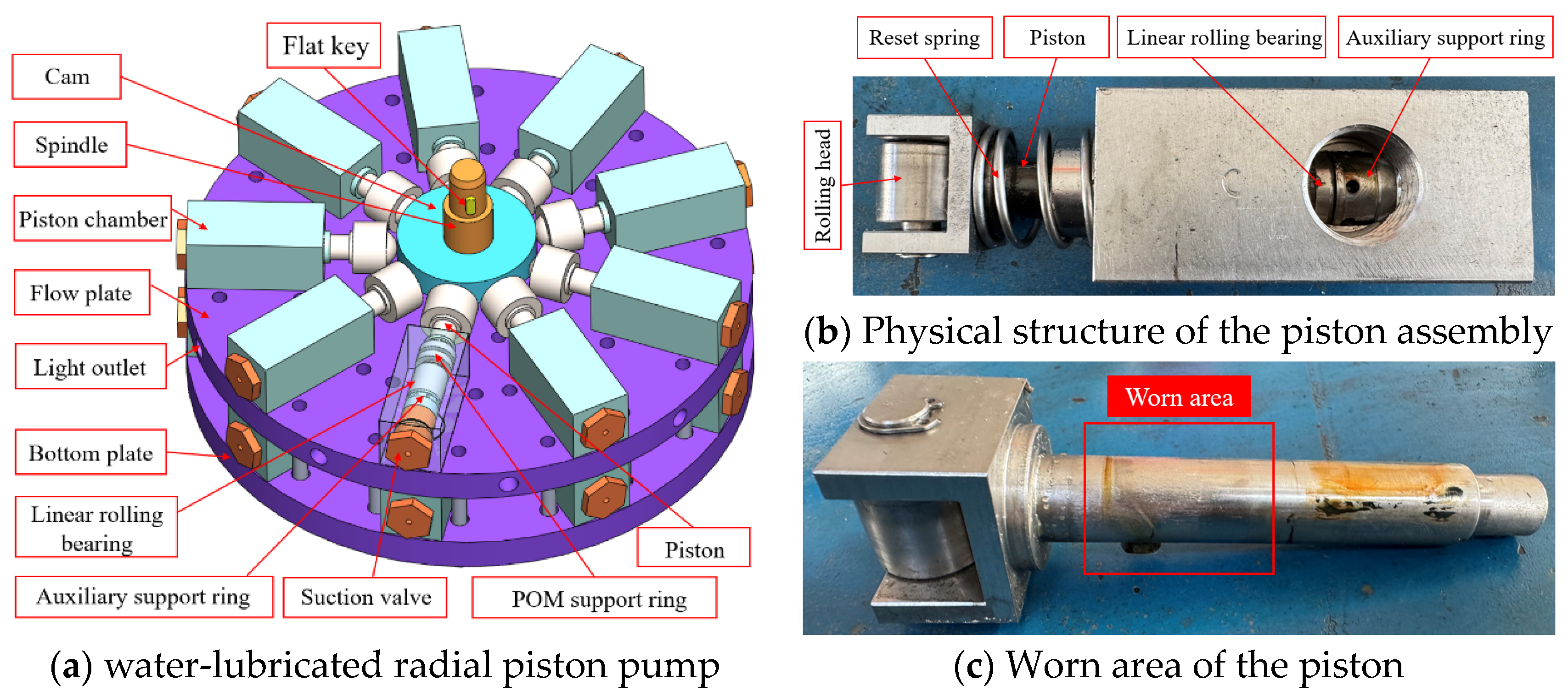
Figure 1a illustrates the overall structure of the seawater-lubricated radial piston pump, which comprises a main shaft, a valve plate, a bottom plate, an eccentric sleeve, deep groove ball bearings, and upper and lower layers of piston assemblies. The pistons in each layer are uniformly distributed along the circumference. The main shaft forms an eccentric cam through the installation of the eccentric sleeve and deep groove ball bearings. The piston cylinder is equipped with a return spring at the front end, which ensures tight contact between the roller ball head of the piston rod and the outer circumferential surface of the eccentric cam. During operation, the seawater-lubricated radial piston pump is fully immersed in the liquid working medium. The motor drives the central cam mounted on the main shaft of the piston pump to rotate, and under the interaction between the eccentric cam and the return spring, the reciprocating linear motion of the piston rod is achieved.
Figure 1.
Research object.
Under such motion and hydraulic action, two main friction pairs are formed in the water pump: the cam/ball head pair and the piston/cylinder liner pair. Among these, the cam/ball head pair exhibits rolling friction, which results in a lower friction coefficient compared to sliding friction pairs. In contrast, the piston/cylinder liner pair is more complex, with its structure shown in Figure 1b. The piston is guided by the combined action of a rolling linear bearing, an auxiliary support ring, and a POM support ring to ensure centering as much as possible and to minimize the contact area with the cylinder port. However, the presence of the cam inevitably induces lateral forces on the piston. Moreover, the characteristics of the water medium hinder the formation of effective lubrication at the cylinder port, leading to severe friction and lubrication issues for the piston–cylinder pair. A worn piston is shown in Figure 1c.
2.2. Sample Preparation
2.2.1. Material Composition
The piston–piston chamber friction pair consists of two groups of counterface materials: the 316L stainless steel/modified EP coating pair corresponds to the piston rod–cylinder port friction pair, while the polyoxymethylene (POM)/modified EP coating pair corresponds to the piston rod–support ring friction pair. Accordingly, the upper specimens in the tests were 316L stainless steel balls and POM balls, whereas the lower specimens were composed of 316L stainless steel substrates coated with modified EP coatings containing different mass fractions of graphene. The friction and wear characteristics of the 316L stainless steel substrate and coatings with varying compositional parameters were evaluated under water-lubricated conditions at different loads, aiming to investigate the influence of material composition on tribological performance. The specifications and dimensions of the test specimens are presented in Table 1. Graphene, graphene oxide, and waterborne epoxy resin were selected for fabricating the lower specimen coatings. Graphene exhibits a monolayer flake structure, while graphene oxide was prepared using the Hummers method. The main chemical reagents used in the experiments are listed in Table 2.
Table 1.
Parameters of test specimens.
Table 2.
Chemical reagents used in the experiments.
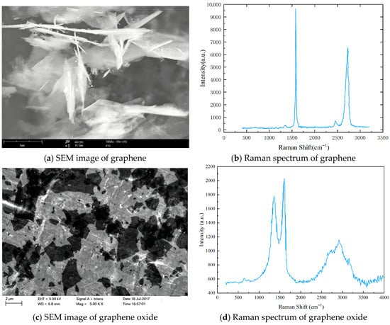
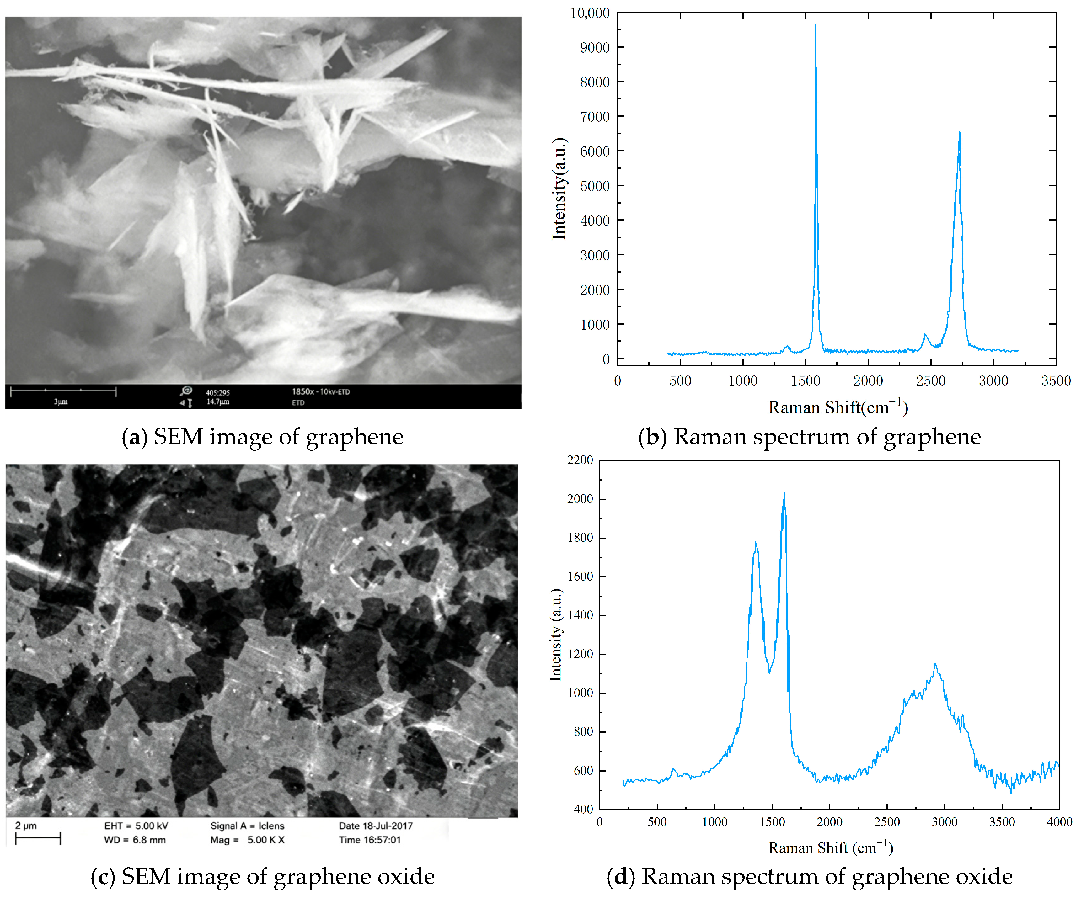
Due to limitations in experimental conditions, commercially available products were used, and the characterization data provided by the manufacturer are cited herein. The specific parameters of graphene and graphene oxide, including the number of layers, particle size, and specific surface area, are presented in Table 3. The SEM images and Raman spectra of graphene and GO are shown in Figure 2.
Table 3.
Characterization of graphene and graphene oxide.
Figure 2.
Material characterization of graphene and graphene oxide.
2.2.2. Preparation Method
A specific amount of epoxy resin was weighed using an electronic balance and placed into a beaker. Graphene and graphene oxide with mass fractions of 0 wt.%, 0.2 wt.%, 0.4 wt.%, 0.6 wt.%, 0.8 wt.%, and 1.0 wt.% were added to the epoxy resin, followed by ultrasonic dispersion for 30 min and mechanical stirring using a magnetic stirrer for another 30 min. Subsequently, a curing agent was added at an epoxy-to-curing agent mass ratio of 3:1, and the mixture was stirred at low speed for 15 min to obtain the coating material.
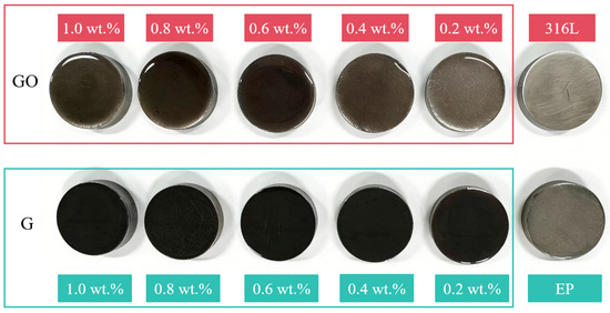
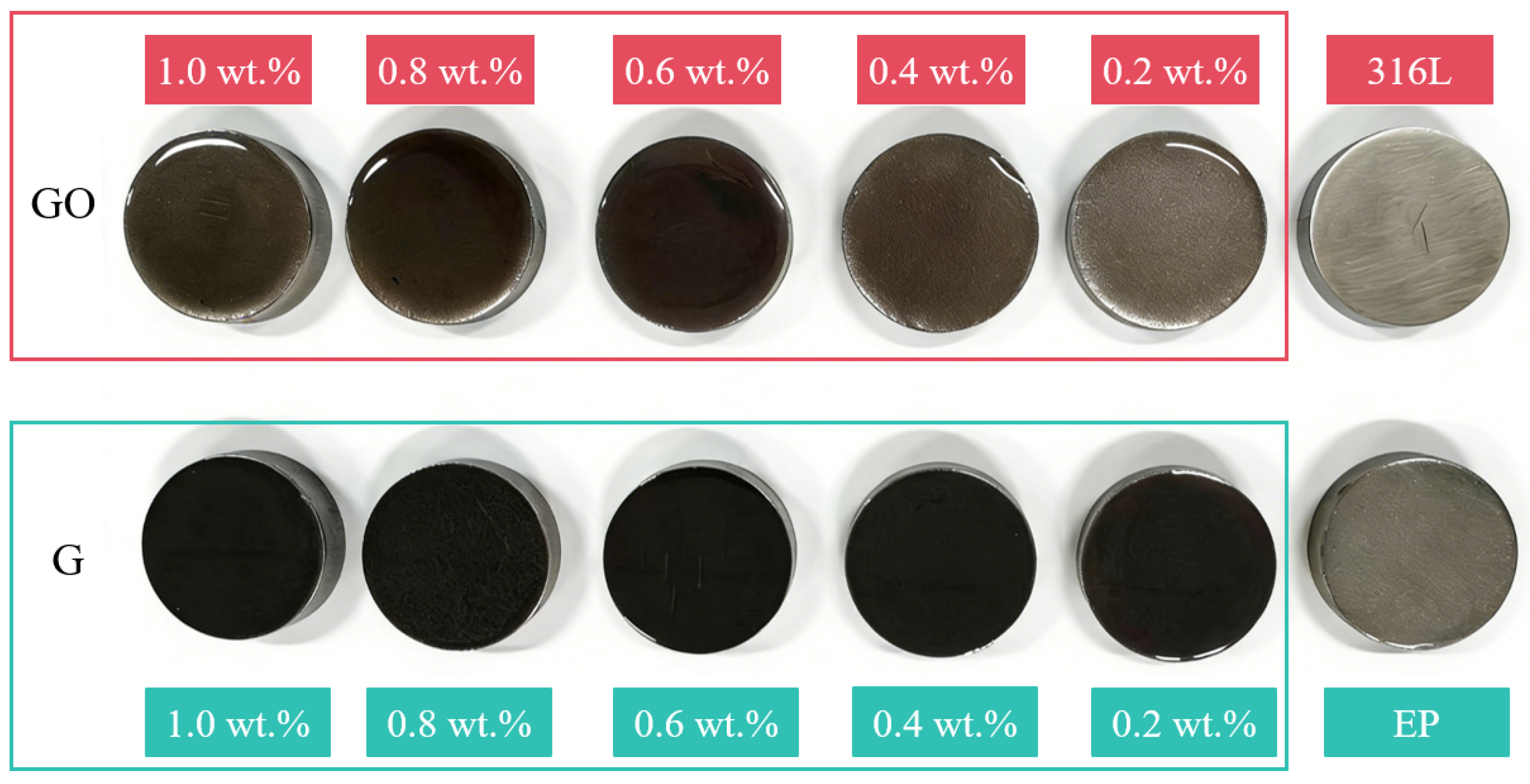
The 316L stainless steel lower specimens were sequentially ground with 200-, 400-, 600-, 800-, and 1000-grit sandpaper. The substrates were then immersed in anhydrous ethanol and cleaned in an ultrasonic cleaner to remove surface oil and impurities, followed by drying. Prior to coating preparation, the substrates were fixed on a flat surface, and amount of the coating material was placed in front of the applicator blade. The applicator was moved to evenly distribute the coating material over the substrate surface. The coated specimens were then cured in an incubator for 2 h, followed by curing at room temperature for 24 h. The instruments and equipment used in the experiments are listed in Table 4, and the prepared samples are shown in Figure 3.
Table 4.
Instruments and equipment used in the experiments.
Figure 3.
Friction and wear test specimens.
2.3. Testing Methods and Conditions
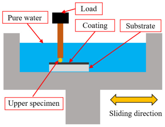
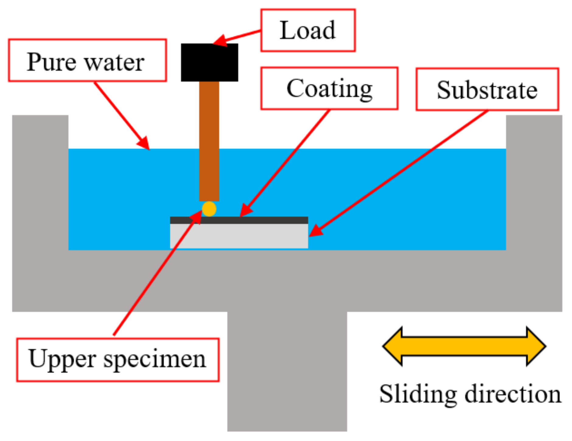
A TriboStudio (Taoyuan City, Taiwan) TS20 high-performance friction and wear tester was employed in this study, with a ball-on-disc contact configuration to simulate the actual operating conditions of the piston–piston chamber friction pair. The upper specimen was loaded with a precise normal force through a high-precision weight and lever system. The load, velocity, test duration, and reciprocating frequency were set using the control software. The lower specimen was mounted and fixed within a liquid cell using a fixture, and deionized water was added to the cell to simulate the lubrication conditions of the friction pair under actual operating conditions. The liquid cell was secured onto the test platform, as shown in Figure 4. The material parameters are presented in Table 5.
Figure 4.
Schematic diagram of the friction and wear test.
Table 5.
Material parameters of the counterface pairs.
Although the coating is a viscoelastic material, in this study, the coating thickness (150 μm) is significantly smaller than the macroscopic contact radius of the counterface (5 mm). Moreover, the applied load is relatively low, and the elastic modulus of the coating is far lower than that of the metallic substrate. Consequently, the contact deformation is primarily constrained by the rigid metallic substrate, with elastic deformation dominating the response, which approximates the assumptions of Hertzian theory [39]. Nevertheless, it must be acknowledged that this simplified model has inherent limitations: it neglects the viscoelastic dissipation of the polymer coating, disregards the hydrodynamic pressure effect of the water film, and omits the influence of surface roughness.
The formula for calculating the combined elastic modulus in Hertzian contact theory is as follows:
where E* is the reduced elastic modulus (MPa) and ν is Poisson’s ratio.
In the ball-on-plane contact model, the contact radius is calculated using the formula
where R is the ball radius (mm), F is the normal load (N), and a is the contact radius (mm).
The maximum contact stress (MPa) is given by
The lateral force acting on the piston is calculated as
where F represents the driving force with a value of 4900 N, α denotes the maximum pressure angle of the cam with a value of 3.37°, the piston radius R is taken as 10 mm, and the contact length L is taken as 8 mm. The piston is coated with an epoxy resin coating.
T = Fsin α = 4900 × sin 3.37° = 288 N
Based on calculations, the lateral force on the piston is approximately 288 N, corresponding to a contact pressure of approximately 62.11 MPa. Through reverse derivation, the required load for the ball-on-disc model was determined to be 1 N, yielding a contact pressure of approximately 70.5 MPa, which was used to realistically simulate and verify the friction-reducing and anti-wear performance of the coating under normal operating conditions. Additionally, to investigate the tribological performance and durability of the coating under higher stress conditions, a load of 7 N was selected as a comparative condition. The maximum contact stress corresponding to this load is 134.5 MPa, approximately 2.2 times that of the actual operating condition, which was employed for accelerated wear testing and extreme condition evaluation.
According to the Hertzian contact stress theory, the contact pressure of the piston–piston chamber friction pair was calculated. Loads of 1 N and 7 N were applied using weights to simulate the force conditions under no-load and high-pressure operating conditions, respectively. The specific parameters are presented in Table 6.
Table 6.
Experimental parameters.
Prior to and after testing, the specimens were ultrasonically cleaned in anhydrous ethanol for 5 min to remove contaminants. Each test was conducted at least three times, and the average values along with standard deviations were recorded. At the laboratory of China University of Mining and Technology (Beijing, China), the specimen surfaces were analyzed using a CIQTEK, Hefei, China, DB500 scanning electron microscope (SEM), an Rtec Instruments, San Jose, CA, USA, UP-3000 white light interferometer, and a Dataphysics, Filderstadt, Germany, OCA 20 contact angle analyzer. The Mountainsmap software Mountains 10.3.1 was employed to extract the cross-sectional profile of the wear track and the surface wear volume . The wear rate was calculated using the following expression:
where Wv is the wear volume (mm3), obtained by integrating the cross-sectional profile of the wear track measured using white light interferometry, Fl is the normal load (N), and S is the sliding distance (m).
3. Results and Discussion
3.1. Friction Coefficient
3.1.1. 316L-316L Friction Pair
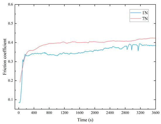
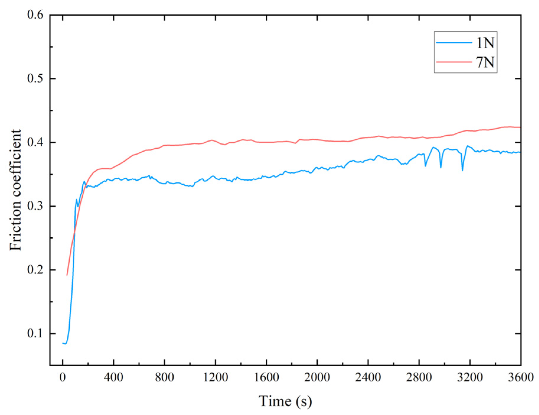
To evaluate the performance of the modified EP coating, friction coefficient tests were conducted on the 316L ball–316L substrate counterface pair under water-lubricated conditions, and the resulting friction coefficient–time curves are shown in Figure 5. Under loads of 1 N and 7 N, the friction coefficient of the 316L ball–316L friction pair increased rapidly within 200 s, gradually transitioning from a running-in period to a stable wear stage. After stabilization, the friction coefficient was approximately 0.39 under a load of 1 N and approximately 0.42 under a load of 7 N. The test results indicate that the 316L-316L friction pair exhibits a relatively high friction coefficient under water-lubricated conditions, and an increase in the load leads to a higher friction coefficient, which adversely affects the operating efficiency and service life of the piston pump.
Figure 5.
Friction coefficient of the 316L counterface pair.
3.1.2. 316L-G/EP Coating Friction Pair
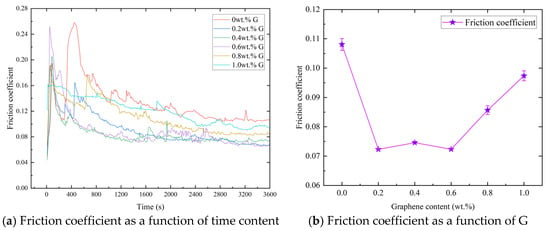
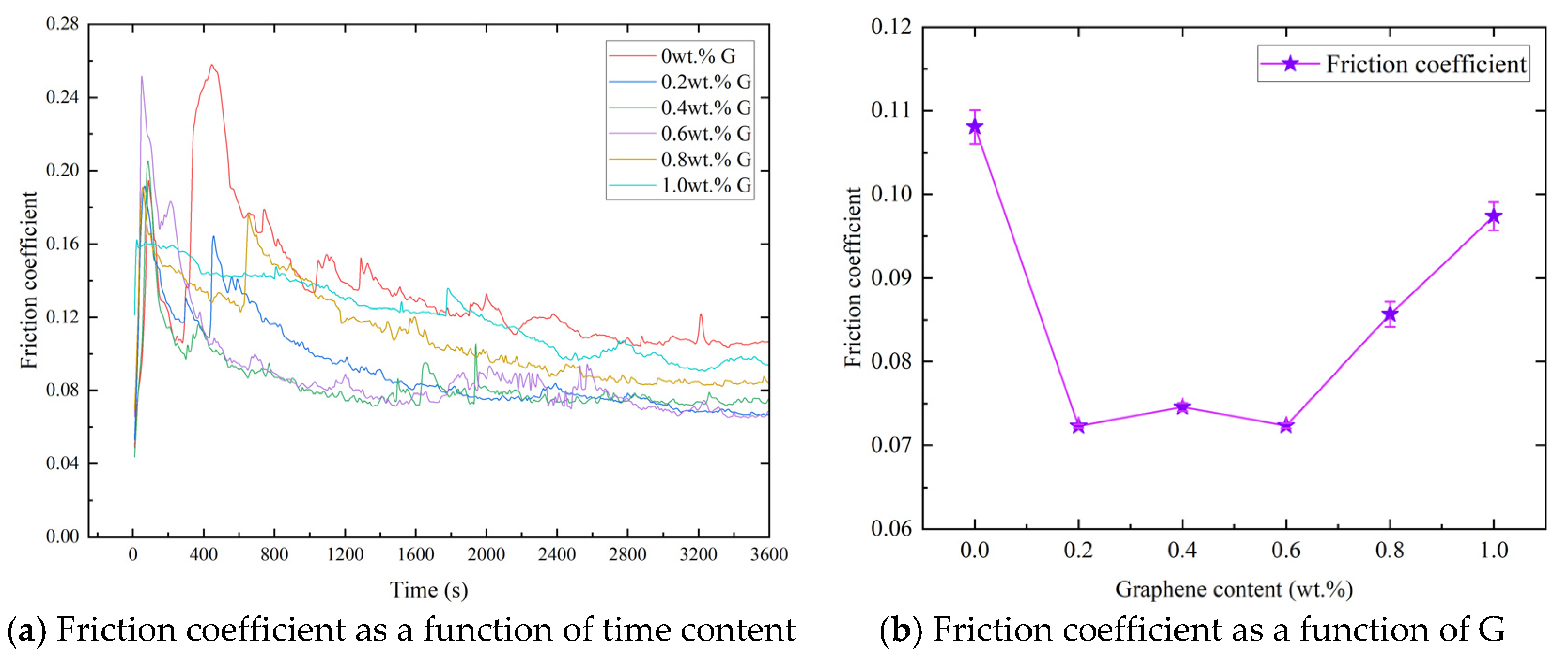
The friction coefficient–time curves of the 316L-G/EP coating friction pair with varying graphene contents under a load of 1 N are shown in Figure 6a. The friction coefficient exhibited drastic fluctuations at the initial stage of motion, increasing rapidly within 5 min and gradually stabilizing thereafter, indicating a distinct running-in period for the 316L stainless steel–EP coating friction pair. From the friction coefficient curves, it can be observed that the pure EP coating without graphene exhibited the highest friction coefficient, with a stabilized value of 0.109. The friction coefficients during the stable wear stage for the counterface pairs with different graphene contents under a load of 1 N are presented in Figure 6b. As the graphene content increased, the friction coefficient first decreased significantly and then gradually increased. The coating with 0.6 wt.% graphene achieved the lowest stabilized friction coefficient of 0.072, representing a reduction of 33.94% compared with the coating containing 0 wt.% graphene. Compared with the 316L-316L counterface pair, the stabilized friction coefficient of the 0.6 wt.% graphene coating was reduced by 81.5%.
Figure 6.
Friction coefficient of the 316L-G/EP coating under a load of 1 N.
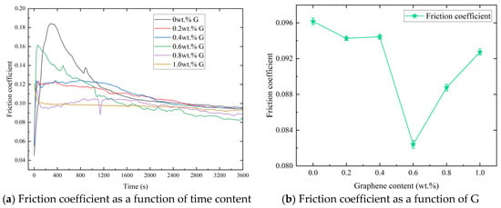
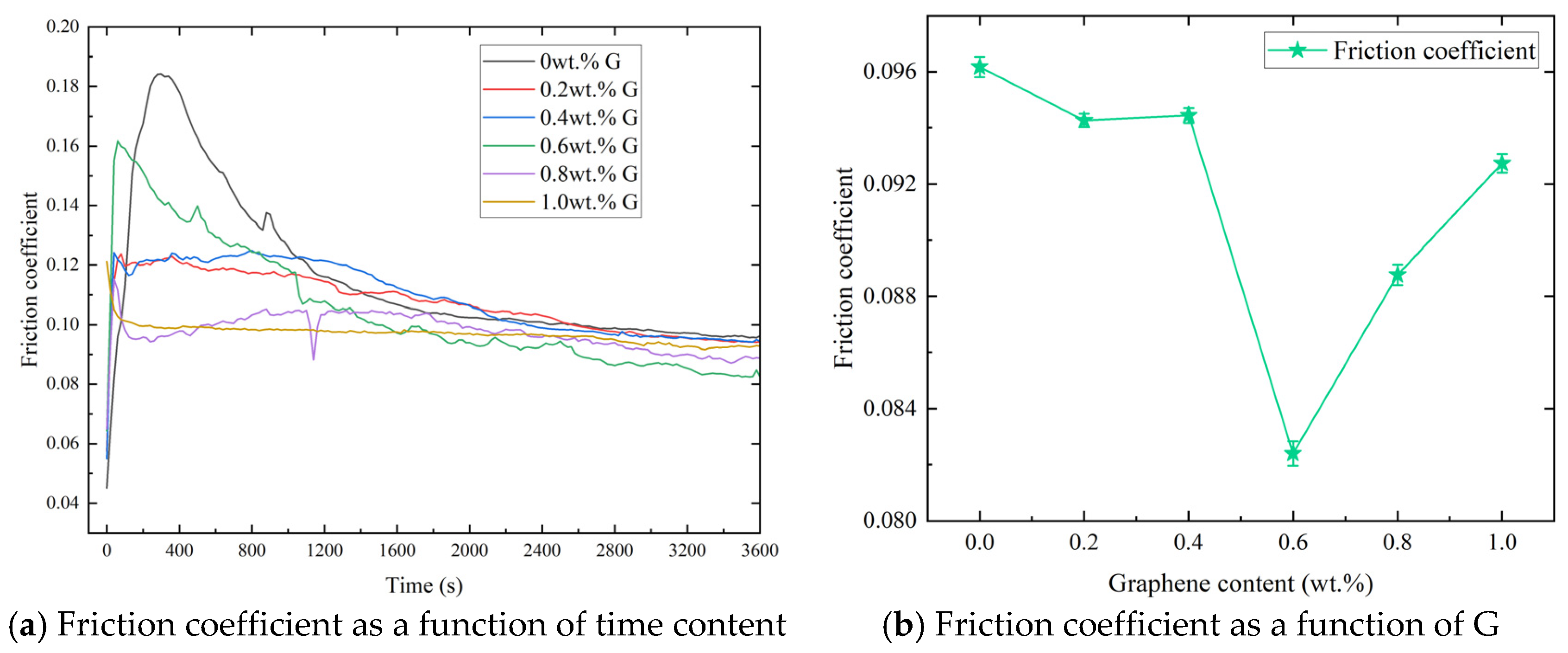
The friction coefficient–time curves of the 316L-G/EP coating friction pair with varying graphene contents under a load of 7 N are shown in Figure 7a. The friction coefficient exhibited drastic fluctuations at the initial stage of motion, increasing rapidly within 2 min and gradually stabilizing thereafter, indicating that the 316L stainless steel–EP coating friction pair still exhibited a distinct running-in period under a load of 7 N, albeit with a shortened duration. From the friction coefficient curves, it can be observed that as the graphene content increased, the friction coefficient first decreased and then increased. The pure EP coating exhibited the highest stabilized friction coefficient, with a value of 0.096. The friction coefficients during the stable wear stage for the counterface pairs with different graphene contents under a load of 7 N are presented in Figure 7b. The coating with 0.6 wt.% graphene achieved the lowest stabilized friction coefficient of 0.083, representing a reduction of 11.42% compared with the 0 wt.% graphene coating. Compared with the friction coefficient curve of the 316L-316L counterface pair, the stabilized friction coefficient of the 0.6 wt.% graphene coating was reduced by 80.2%.
Figure 7.
Friction coefficient of the 316L-G/EP coating under a load of 7 N.
In summary, under both 1 N and 7 N loads, the friction coefficients of all graphene-modified EP coatings were lower than that of the 316L ball–316L substrate friction pair. Among all compositional parameters, the EP coating with 0.6 wt.% graphene exhibited the lowest friction coefficient, indicating the best friction-reducing performance under water-lubricated conditions. The pure EP coating without graphene showed the highest friction coefficient, demonstrating inferior lubricating performance compared with all graphene-modified coatings.
3.1.3. 316L-GO/EP Coating Friction Pair
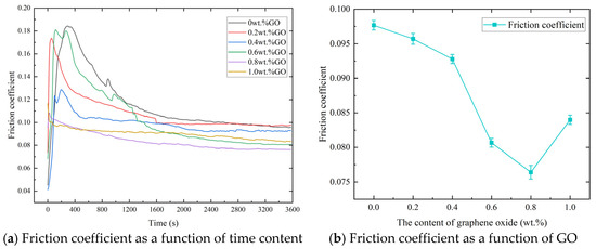
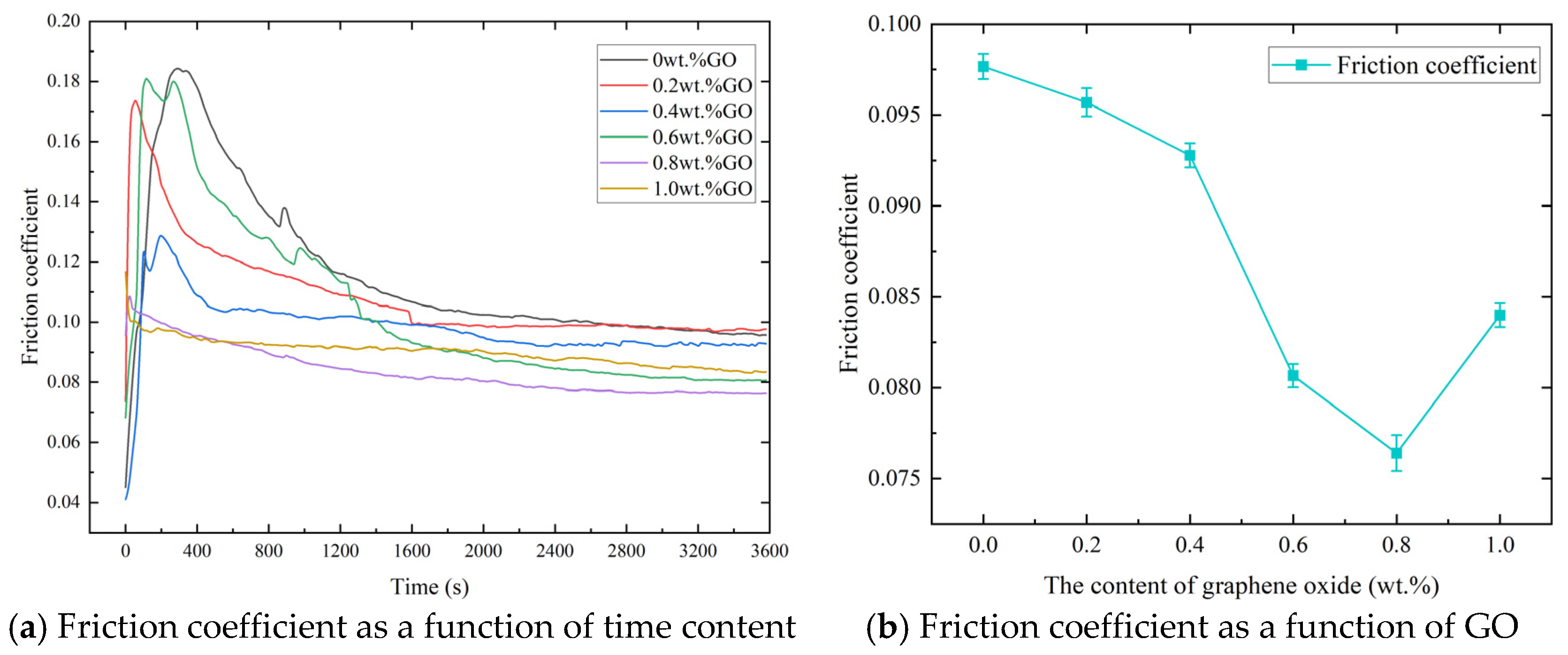
The friction coefficient–time curves of the 316L-GO/EP coating friction pair with varying graphene oxide contents under a load of 1 N are shown in Figure 8. The friction coefficient exhibited drastic fluctuations at the initial stage of motion, increasing rapidly within 4 min and subsequently maintaining stability within a certain range, indicating that the 316L stainless steel–graphene oxide modified EP coating friction pair also exhibits a distinct running-in period. The pure EP coating exhibited the highest friction coefficient, with an average value of 0.106. The friction coefficients during the stable wear stage for the counterface pairs with different graphene oxide contents under a load of 1 N are presented in Figure 8. As the graphene oxide content increased, the friction coefficient first decreased significantly and then gradually increased. The coating with 0.8 wt.% graphene oxide achieved the lowest stabilized friction coefficient of 0.089, representing a reduction of 16.1% compared with the pure EP coating. Compared with the friction coefficient curve of the 316L-316L counterface pair, the lowest average friction coefficient was reduced by 64.4%.
Figure 8.
Friction coefficient of the 316L-GO/EP coating under a load of 1 N.
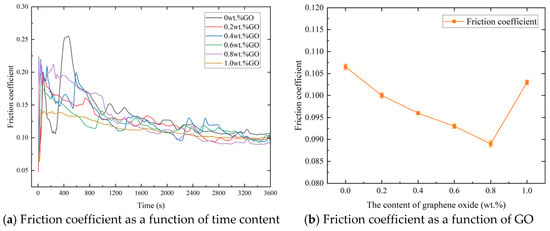
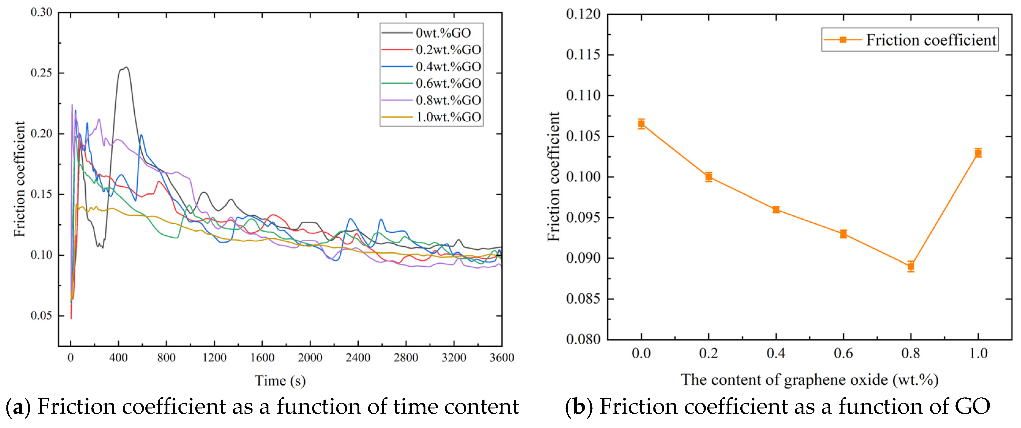
The friction coefficient curves of the 316L-GO/EP coating friction pair with varying graphene oxide contents under a load of 7 N are shown in Figure 9a. The friction coefficient exhibited drastic fluctuations at the initial stage of motion, increasing rapidly within 5 min and subsequently maintaining stability within a certain range, indicating that the 316L stainless steel–graphene oxide modified EP coating friction pair also exhibits a distinct running-in period under a load of 7 N. The pure EP coating exhibited the highest friction coefficient, with an average value of 0.096. The friction coefficients during the stable wear stage for the counterface pairs with different graphene oxide contents under a load of 7 N are presented in Figure 9b. As the graphene oxide content increased, the friction coefficient first decreased significantly and then gradually increased. The coating with 0.8 wt.% graphene oxide achieved the lowest stabilized friction coefficient of 0.076, representing a reduction of 20.8% compared with the 0 wt.% graphene oxide-modified EP coating. Compared with the friction coefficient curve of the 316L-316L counterface pair, the lowest average friction coefficient was reduced by 81.9%.
Figure 9.
Friction coefficient of the 316L-GO/EP coating under a load of 7 N.
In summary, under both 1 N and 7 N loads, the friction coefficients of all graphene oxide-modified EP coatings were lower than that of the 316L ball–316L substrate friction pair. Among all compositional parameters, the EP coating with 0.8 wt.% graphene oxide exhibited the lowest friction coefficient, indicating the best lubrication performance under water-lubricated conditions. The pure EP coating without graphene oxide showed the highest friction coefficient, demonstrating inferior lubricating performance compared with the GO/EP coatings.
3.2. Wear Volume
The cross-sectional profiles of the contact surfaces after wear testing under a load of 7 N for coatings with varying graphene contents are shown in Figure 10a, and the corresponding wear track morphologies are presented in Figure 10b–f. The results indicate that as the graphene content increases, the wear rate of the friction pair first decreases and then increases, and the wear track depth exhibits a similar trend of initially decreasing and subsequently increasing. The pure EP coating without graphene exhibits a maximum wear track depth of 4.4 μm, whereas the EP coating with 0.6 wt.% graphene achieves a maximum wear track depth of only 0.6 μm. Under identical test conditions, the coating containing 0.6 wt.% graphene exhibits the smallest wear volume. Compared with the pure EP coating without graphene, the wear rate is reduced by 77.19%; compared with the uncoated 316L surface, the wear rate is reduced by 66.57%. These results indicate that under water-lubricated conditions, the EP coating containing 0.6 wt.% graphene demonstrates the optimal lubrication performance.
Figure 10.
Wear track morphology and cross-sectional profile of the 316L-G/EP counterface pair.
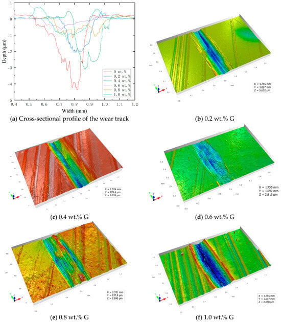
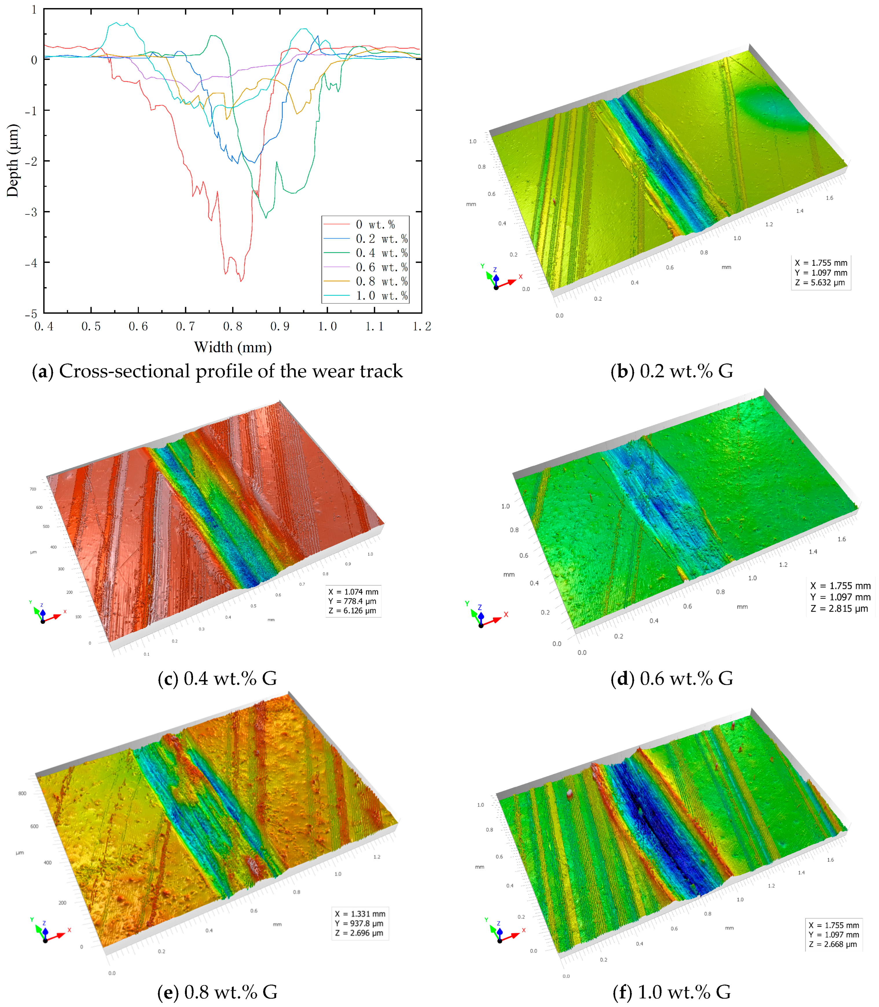
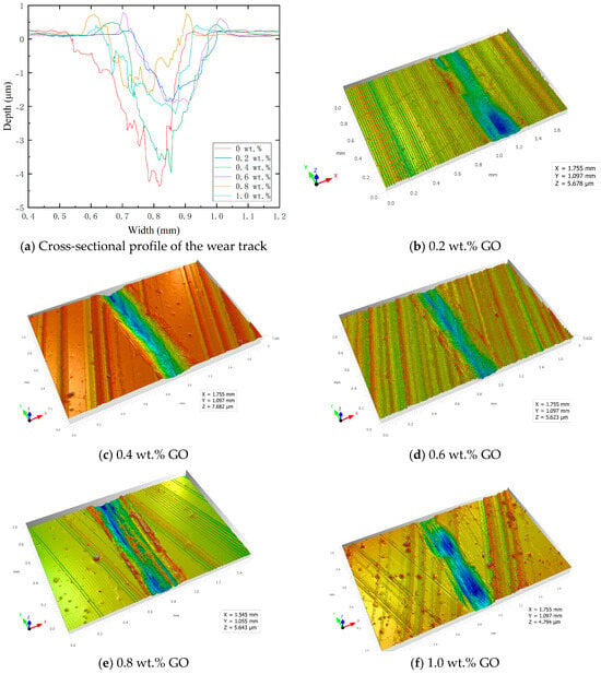
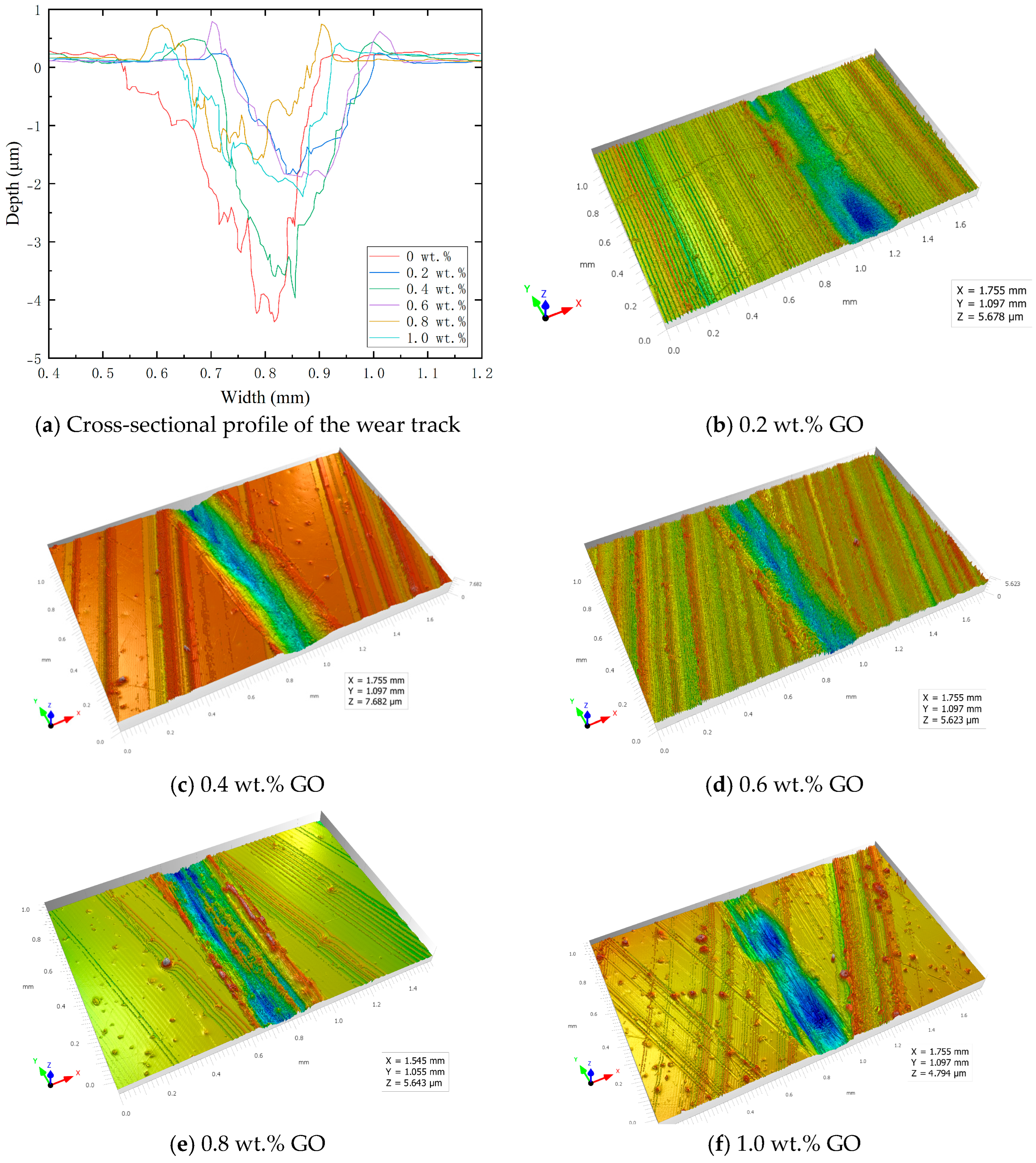
The cross-sectional profiles of the contact surfaces after wear testing under a load of 7 N for coatings with varying graphene oxide contents are shown in Figure 11a, and the corresponding wear track morphologies are presented in Figure 11b–f. As the graphene oxide content increases, the wear volume on the friction pair surface exhibits a trend of first decreasing and then increasing, and the wear track depth similarly follows a pattern of initial reduction followed by an increase. The pure EP coating without graphene oxide exhibits a maximum wear track depth of 4.4 μm, whereas the EP coating with 0.8 wt.% graphene oxide achieves a maximum wear track depth of 1.5 μm. A comparison of the wear rates of friction pairs with different graphene oxide contents reveals that under identical test conditions, the coating with 0.8 wt.% graphene oxide achieves the smallest wear volume. Compared with the pure EP coating without graphene oxide, the wear rate is reduced by 64.48%; compared with the uncoated 316L surface, the wear rate is reduced by 48.39%. These results indicate that under water-lubricated conditions, the 0.8 wt.% graphene oxide-modified EP coating exhibits the best lubrication performance among the various proportions of graphene oxide-modified EP coatings.
Figure 11.
Wear track morphology and cross-sectional profile of the 316L-GO/EP counterface pair.
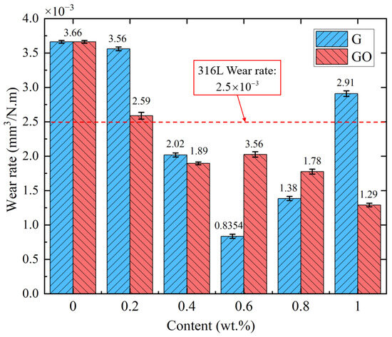
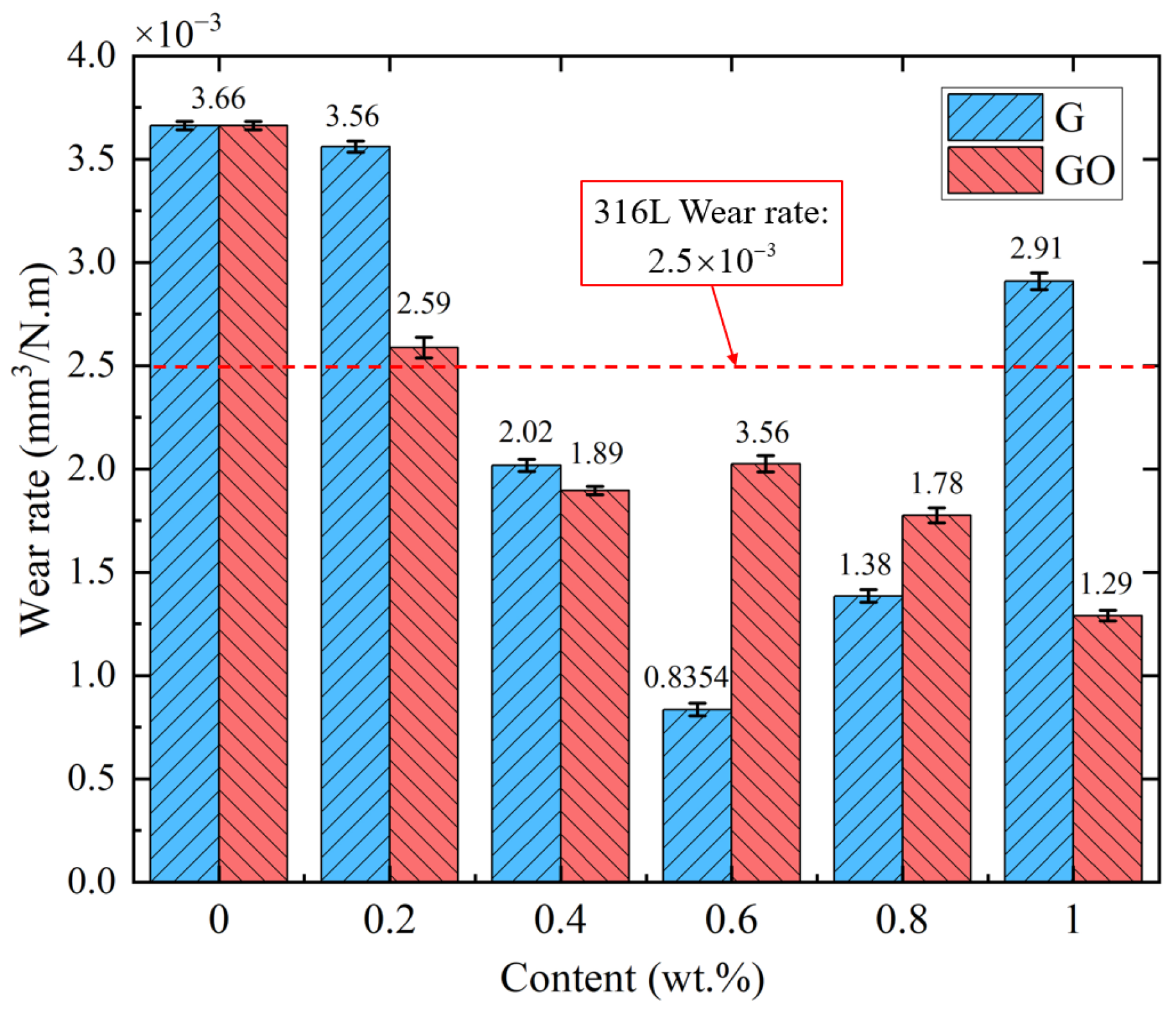
The wear rates of the contact surfaces for coatings with varying contents of graphene and graphene oxide after wear testing are presented in Figure 12. Both graphene-modified and graphene oxide-modified EP coatings can significantly reduce the wear rate under water-lubricated conditions. Graphene achieves optimal anti-wear performance at a content of 0.6 wt.%, primarily relying on its layered structure to form a physical transfer film that enables self-lubrication. Graphene oxide exhibits the best performance at a content of 0.8 wt.%, leveraging the hydrophilicity of its oxygen-containing functional groups to form a hydrated lubrication film in the aqueous medium. The graphene-modified EP coating shows a slightly superior reduction in wear rate compared with the graphene oxide-modified counterpart; however, graphene oxide demonstrates better water dispersibility and maintains relatively favorable lubrication performance even at higher contents. Excessive addition of either filler leads to deterioration of the coating’s wear resistance.
Figure 12.
Comparison of wear rates.
3.3. Wear Morphology
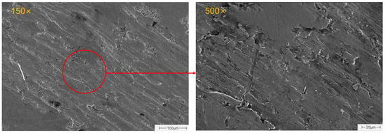
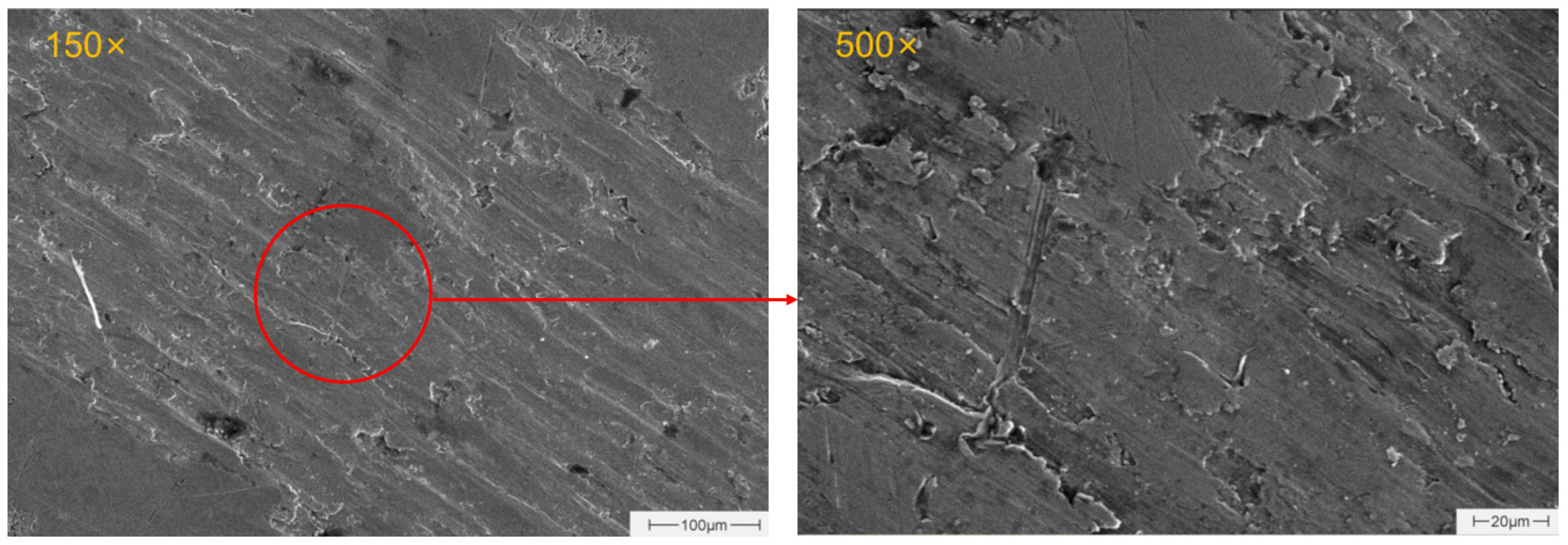
Figure 13 presents scanning electron microscopy images of the 316L-316L counterface pair surface at magnifications of 150× and 500×. Under low magnification, the wear track exhibits continuous parallel grooves with a relatively deep overall profile, and irregular pits formed by material spalling are distributed on the surface. Under high magnification, distinct plowing grooves and plastic deformation bands can be observed within the wear track, accompanied by pronounced material buildup and extrusion at the groove edges. Meanwhile, localized adhesive tearing marks are visible on the worn surface. In addition, microcracks and topographic undulations are observed at the bottom and sidewalls of the plowing grooves. These morphological characteristics indicate that multiple wear mechanisms are involved in the wear process of this counterface pair: the plowing grooves and plastic deformation bands are typical morphologies of abrasive wear; the adhesive tearing marks correspond to surface damage induced by adhesive wear; and the microcracks and topographic undulations represent manifestations of surface fatigue damage under cyclic stress conditions.
Figure 13.
SEM images of the wear track on the 316L-316L counterface pair.
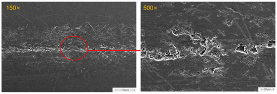
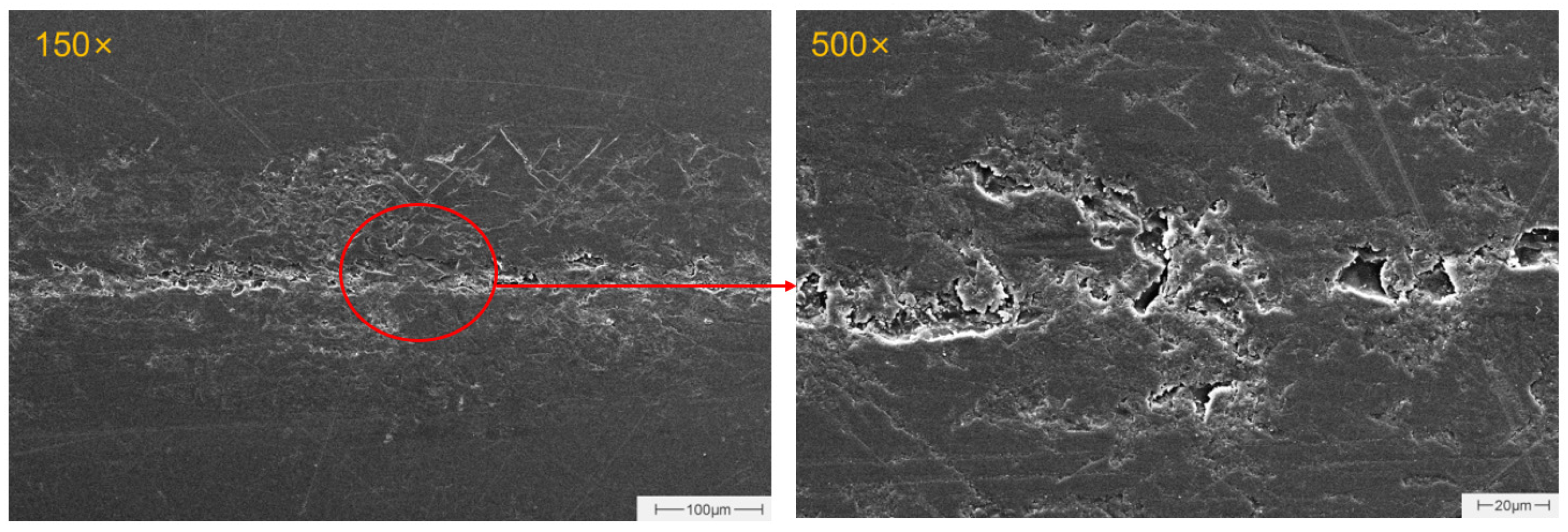
Figure 14 presents scanning electron microscopy images of the 316L-EP coating counterface pair surface at magnifications of 150× and 500×. As shown in the figure, the worn surface morphology of the unmodified epoxy resin coating is rough, with the wear region exhibiting a wide and continuous band-like distribution, accompanied by pronounced material accumulation and spalling pits in local areas. Under high magnification, fine and shallow micro-plowing grooves along with irregular spalling pores are distributed across the worn surface; extensive layered delamination and brittle fracture features are present; and in local regions, debris and irregular pits formed by material tearing can be observed, exhibiting typical characteristics of adhesive tearing and layered delamination of polymer coatings.
Figure 14.
SEM images of the wear track on the 316L-EP coating counterface pair.
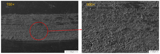
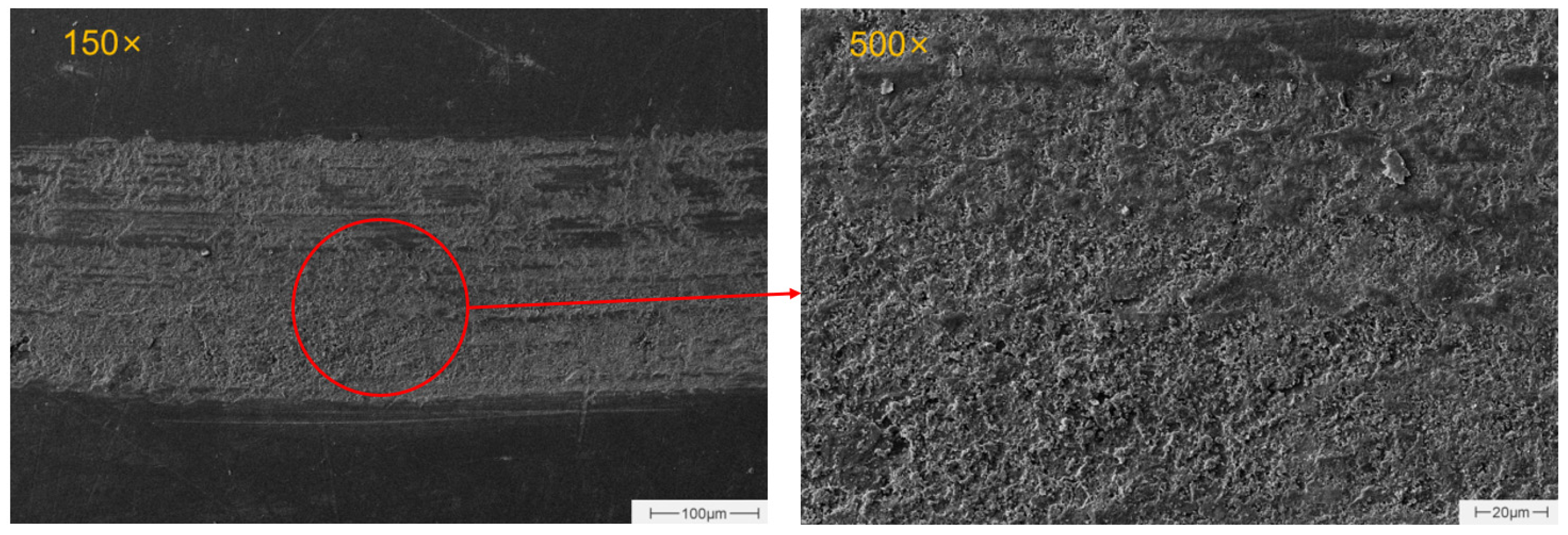
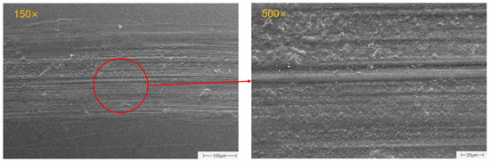
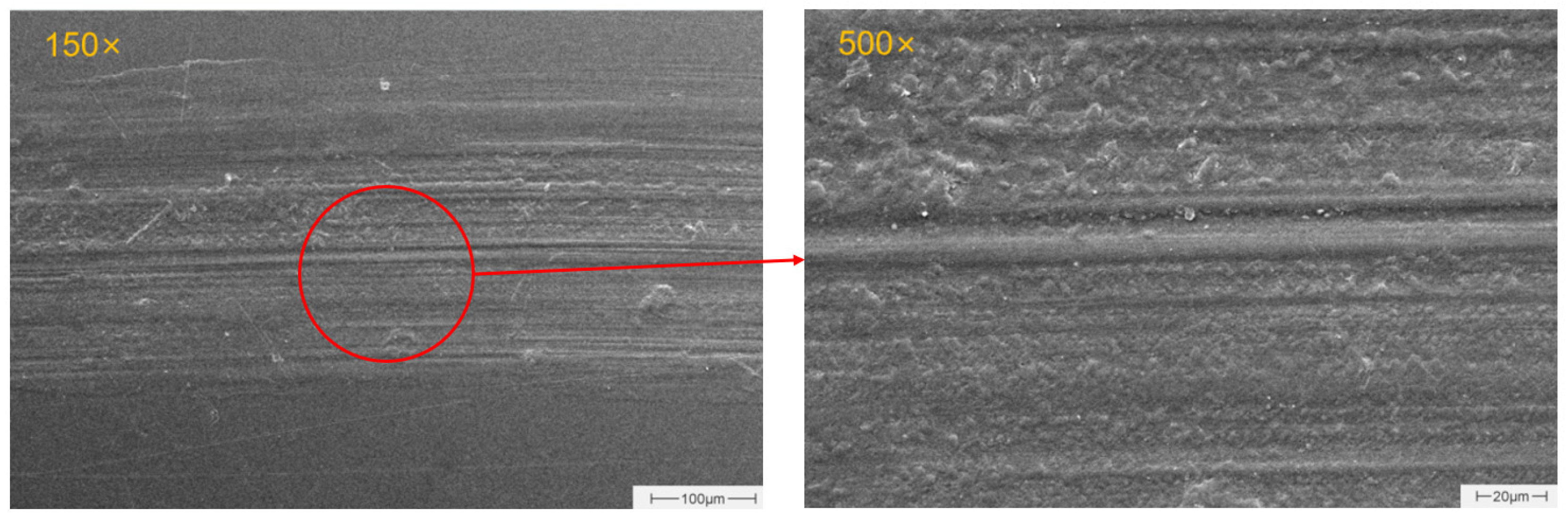
Figure 15 presents the SEM morphology of the contact surface of the 316L–G/EP coating counterface pair after wear testing. Under a low-magnification field of view of 150×, the wear track exhibits a continuous and narrowed band-like distribution, with a clear boundary from the unworn substrate. The worn region is relatively flat overall, with no evidence of extensive material spalling or flocculent accumulation; only shallow, well-aligned parallel micro-grooves in the sliding direction are observable. Under high magnification of 500×, the worn surface exhibits a dense plastic flow deformation morphology, with smooth groove edges and no obvious brittle tearing marks. Only a small amount of fine wear debris is attached locally, and the typical layered delamination and extensive adhesive folding structures observed in the unmodified coating are absent.
Figure 15.
SEM images of the wear track on the 316L–G/EP coating counterface pair.
Figure 16 presents the SEM morphology of the contact surface of the 316L–GO/EP coating counterface pair after wear testing. Under a low-magnification field of view of 150×, the wear track exhibits a continuous oriented band-like distribution, with shallow and well-aligned parallel micro-grooves visible in the sliding direction. The worn region is relatively flat overall, and no extensive material spalling or flocculent accumulation structures are observed. Under high magnification of 500×, the worn surface exhibits a dense microstructure, with smooth and regular groove edges. Only a small amount of fine wear debris particles is attached locally, and no severe damage features such as adhesive tearing or layered delamination are evident.
Figure 16.
SEM images of the wear track on the 316L–GO/EP coating counterface pair.
In summary, the graphene (G)-modified coating exhibited superior friction-reduction and wear-resistance properties compared to the graphene oxide (GO)-modified coating, with reductions in the friction coefficient of 33.9% vs. 16.1% and reductions in the wear rate of 77.2% vs. 64.5%, respectively. This disparity is primarily attributed to the following factors: First, G possesses an intact sp2 carbon lattice structure, and the low interlayer shear strength imparts excellent interlayer sliding lubrication capability [40], reducing interfacial shear through the formation of a physical transfer film during the friction process. In contrast, the abundant oxygen-containing functional groups on the GO surface disrupt the intrinsically easy-shear structure of graphene; although beneficial for dispersion, these groups compromise the intrinsic lubricity. Second, the strong hydrophilicity of GO renders it more susceptible to water absorption and swelling under water-lubricated conditions, leading to localized modulus degradation of the coating and impaired load-bearing capacity, although the oxygen-containing functional groups can bind with water molecules to form a hydration lubrication film [41]. Conversely, the relatively higher hydrophobicity of G suppresses water permeation into the coating interior to a certain extent. Furthermore, the functional groups on the GO surface may participate in epoxy crosslinking reactions during the curing process, which, while enhancing interfacial bonding, imposes excessive constraints that restrict the lubricious exfoliation and transfer film formation of the graphene sheets. In comparison, G achieves optimal friction-reduction and wear-resistance performance at a content of 0.6 wt.% through the formation of an effective transfer film, whereas GO, benefiting from its superior dispersibility, exhibits a slower performance degradation at higher contents, with an optimal content of 0.8 wt.%. Regarding the interfacial bonding state, the SEM morphology of the wear tracks revealed no evidence of large-scale pull-out or interfacial debonding of G sheets, indicating that the G/EP coating prepared via the “ultrasonication + mechanical stirring” process possesses favorable interfacial compatibility. This processing approach has been demonstrated in similar studies to effectively promote uniform dispersion and interfacial wetting of fillers within epoxy matrices [42].
3.4. Contact Angle Characteristics
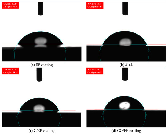
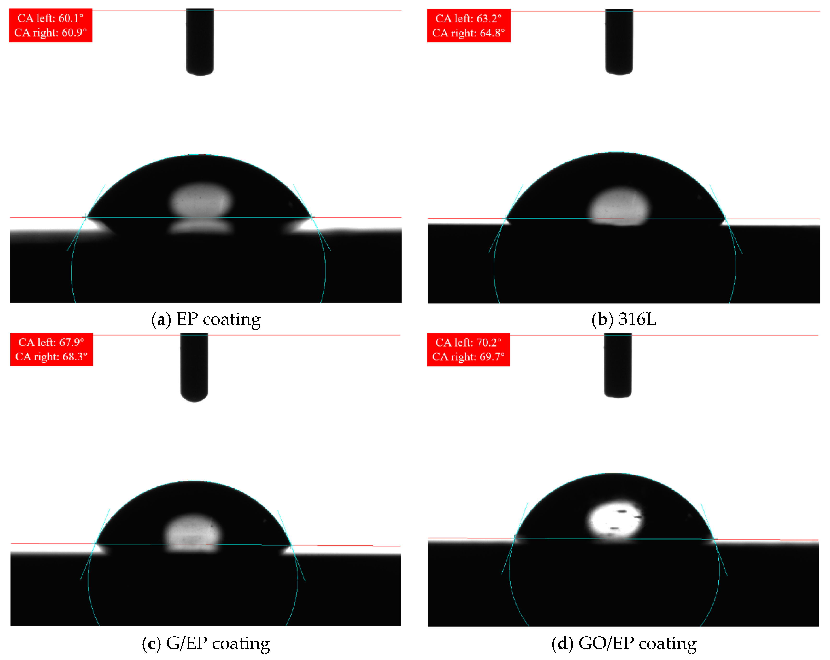
As shown in Figure 17a, the pure epoxy coating exhibits a contact angle of 60°. The presence of polar groups such as hydroxyl and epoxy groups in the epoxy resin molecular structure renders it somewhat hydrophilic, which facilitates the adsorption of water molecules on the surface. As shown in Figure 17b, the 316L stainless steel substrate exhibits a contact angle of 64°, indicating that the substrate surface is in a clean hydrophilic state, providing a favorable foundation for effective coating adhesion. As shown in Figure 17c, after the addition of 0.6 wt.% graphene, the contact angle of the coating increases to 68°, indicating enhanced hydrophobicity. This change can be attributed to the intrinsic hydrophobic nature of graphene—the hexagonal carbon ring structure of graphene repels water molecules, and its uniform distribution on the coating surface forms low-surface-energy microdomains, thereby reducing the overall surface energy of the coating.
Figure 17.
Contact angle measurement results.
As shown in Figure 17d, after the addition of 0.8 wt.% graphene oxide, the contact angle of the coating increases to 70°, which is slightly higher than that of the graphene-modified coating. The oxygen-containing functional groups of graphene oxide can chemically bond with the epoxy matrix, consuming polar groups on the surface and reducing surface energy. Meanwhile, the micro-nano composite structure formed by the graphene oxide sheets on the coating surface induces a roughness-enhanced hydrophobic effect.
For water-lubricated piston–cylinder pairs, hydrophilic surfaces (contact angle < 90°) facilitate the spreading of water films, whereas excessively hydrophilic surfaces (<30°) are prone to swelling-induced failure of the coating. Conversely, strongly hydrophobic surfaces (>90°) exacerbate boundary lubrication due to the difficulty in maintaining a stable water film [43]. In this study, the contact angles of 68–70° correspond to a moderately hydrophobic character, which is conducive to reducing adhesion between the friction pair while retaining a certain capacity for water film formation. All coatings examined in this study fall within this desirable range, thereby establishing a favorable surface wettability foundation for the subsequent achievement of satisfactory water-lubricated tribological performance.
In summary, the aqueous medium in this study plays two primary roles under boundary/mixed lubrication conditions. First, water molecules adsorb onto the coating surface and form a hydration layer, which provides both load-bearing and lubricating functions during frictional shearing. This requires the coating surface to exhibit an appropriate wettability—one that facilitates water film spreading while avoiding excessive permeation that would lead to the plasticization of the matrix. Contact angle measurements indicate that the contact angles of the G/EP and GO/EP coatings increase from approximately 60° for the neat EP to 68° and 70°, respectively, falling within the moderately hydrophobic range conducive to water lubrication. Second, under high-speed operation (1500 r/min), the aqueous medium may generate a certain hydrodynamic pressure effect. Although the applied load in this study is relatively high (16 MPa) and the lubrication regime remains predominantly boundary/mixed, the cooling effect of the water film effectively suppresses the accumulation of frictional heat, thereby mitigating thermal softening failure of the coating.
4. Performance Test
4.1. Coating Preparation and Experimentation
Preparation of Coating on Piston Surface
To validate the tribological performance of the coating under actual operating conditions, experiments were conducted using a single-piston pump test rig. Uncoated and coated piston rods were prepared and tested separately, and the worn surfaces of the piston rods after testing were observed and analyzed using a white light interferometer.
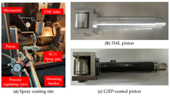
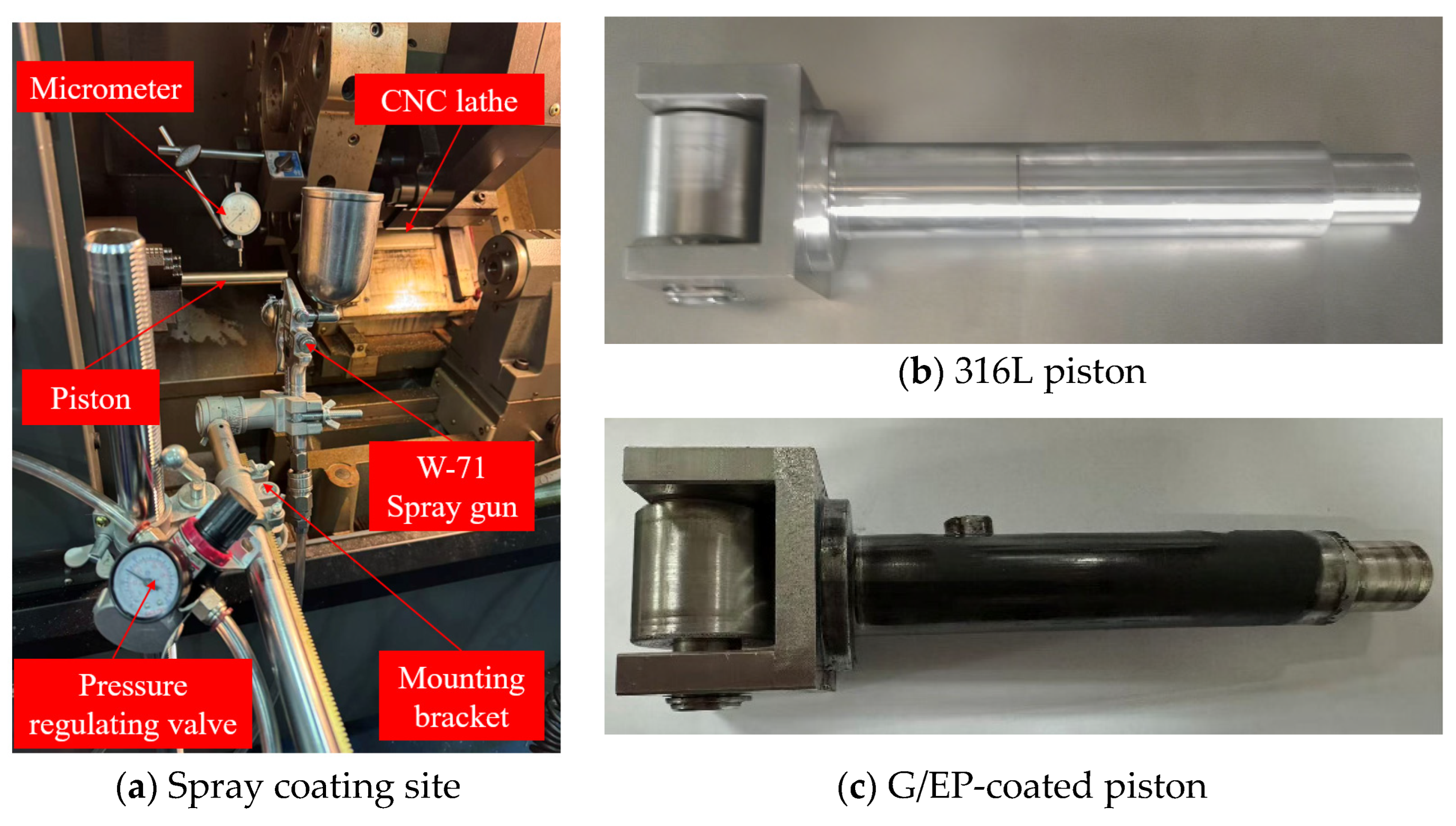
The coating preparation site is shown in Figure 18a. The spraying apparatus mainly consisted of an air supply system, a spray gun, a micrometer, a machine tool, and a fixing bracket. The spray gun used in the experiment was a W-71 model manufactured by Iwata Corporation. The piston rod substrate material was 316L stainless steel, and Figure 18b shows the appearance of the uncoated piston rod. Prior to coating preparation, the outer diameter of the piston rod was machined to φ19.7f6, and the piston rod substrate was ultrasonically cleaned to remove surface contaminants such as oil stains and oxide scale. A graphene-modified EP coating with a content of 0.6 wt.% was selected. The spraying parameters were as follows: spraying time of 11 s, spraying distance of 220 mm, spray gun pressure of 0.29 MPa, and workpiece rotation speed of 30 r/min. The coating was allowed to cure completely for 24 h to complete the preparation process, as shown in Figure 18c. In accordance with the measurement procedures specified in the international standard [44], the coating thickness was determined using a coating thickness gauge at six randomly selected positions in the circumferential direction. The measurement results are presented in Table 7. The arithmetic mean of the measured values is 148 μm with a standard deviation of 3.16 μm, indicating excellent coating uniformity. Additionally, the cylindrical surface dimensions were measured using a micrometer, yielding a value of , meeting the clearance fit requirements for the piston.
Figure 18.
Coating preparation.
Table 7.
Measured values of coating thickness.
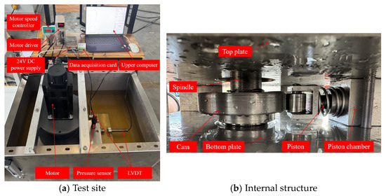
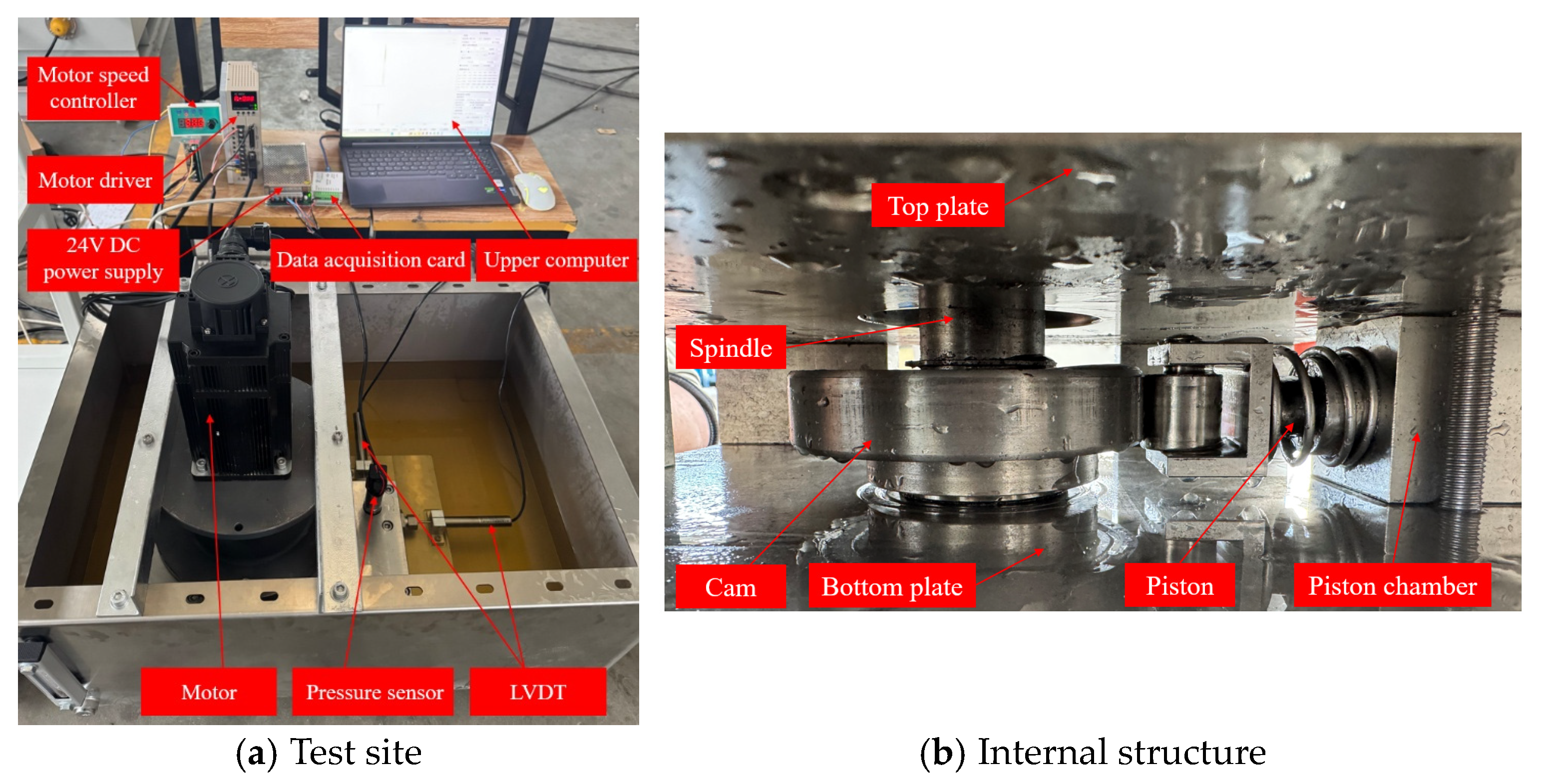
The single-piston pump test rig mainly consists of a water tank, a fixed crossbeam, a permanent magnet synchronous motor, a motor support frame, a coupling, a single-piston pump, an LVDT displacement sensor, a pressure sensor, and other components, as shown in Figure 19a. The internal structure of the single-piston pump remains consistent with that of the complete pump, as illustrated in Figure 19b. The test procedure was as follows: the motor was started and adjusted to a rotational speed of 100 r/min for 5 min to remove air from the pipelines; after stable operation was achieved, the motor speed was increased to the rated speed of 1500 r/min, and the system pressure was adjusted to 16 MPa using a relief valve, followed by continuous operation for 10 h. Upon completion, the single-piston pump was disassembled, and the piston rod was removed.
Figure 19.
Single-piston pump test rig.
4.2. Experimental Results and Analysis
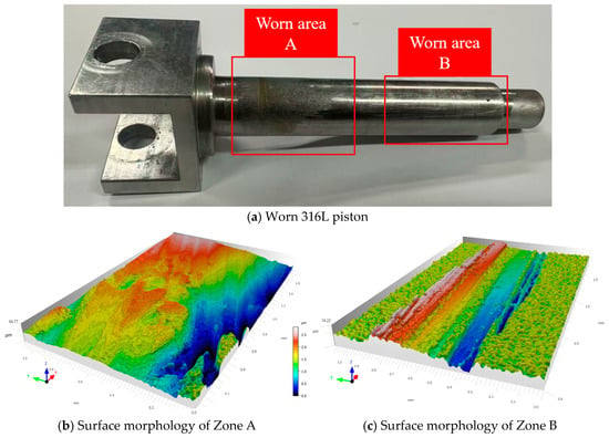
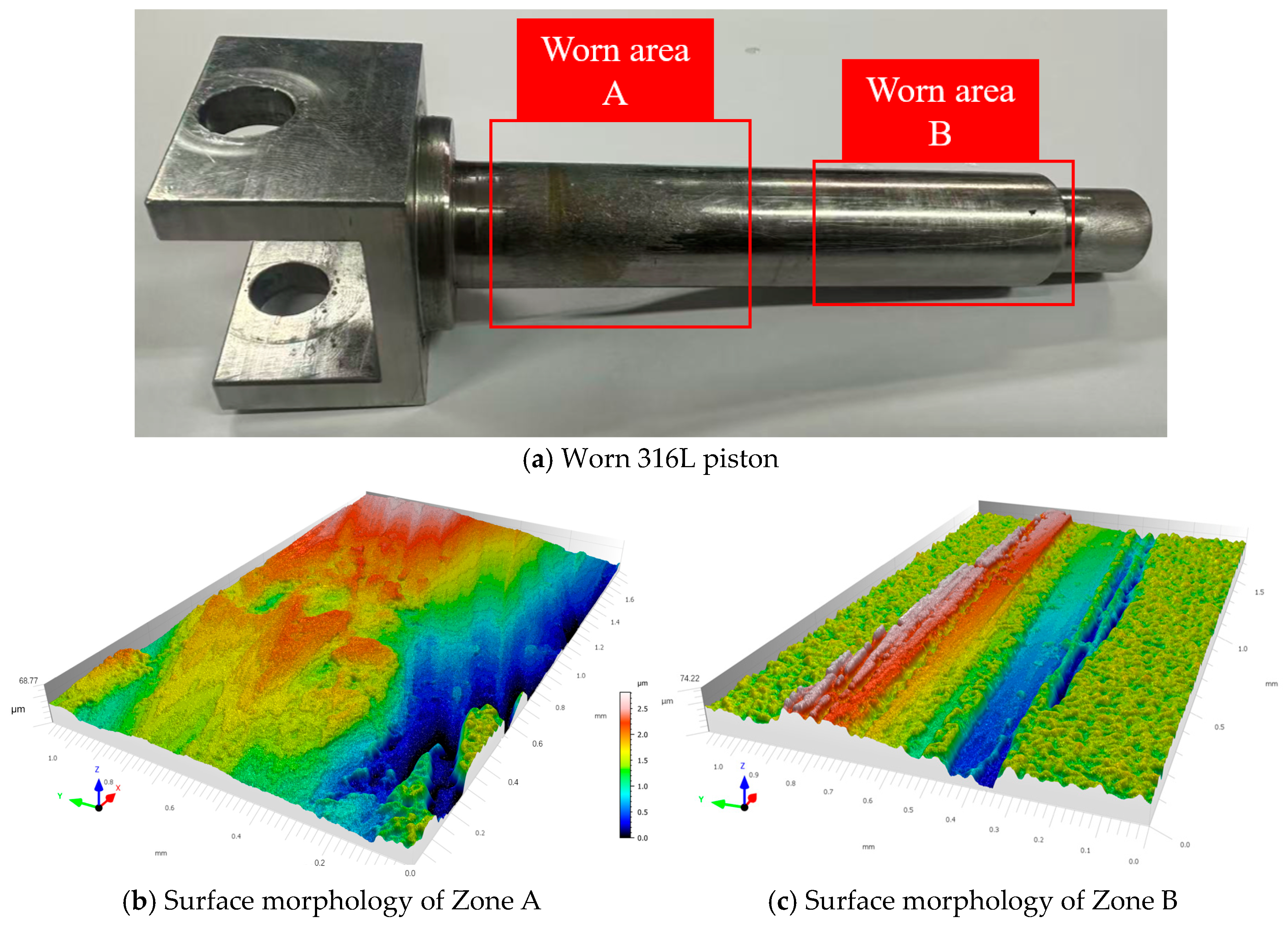
After testing, the piston rod was first ultrasonically cleaned, and a white light interferometer was then used to measure the worn areas on its surface, with the wear rate subsequently calculated. The measured areas were kept consistent before and after testing. As shown in Figure 20a, Area A corresponds to the mating surface between the uncoated 316L piston rod and the piston cylinder port, where obvious wear marks are evident; Area B corresponds to the mating surface between the uncoated 316L piston rod and the linear rolling bearing, where continuous and deep axial scratches are observed. As shown in Figure 20b, for Area A on the surface of the uncoated 316L piston rod, the maximum wear depth is 32.6 μm, the average wear depth is 5.05 μm, and the wear volume per unit area is 5.05 μm3. As shown in Figure 20c, for Area B on the surface of the uncoated 316L piston rod, the maximum wear depth is 21.94 μm, the average wear depth is 3.29 μm, and the wear volume per unit area is 3.28 μm3.
Figure 20.
Surface morphology of the worn 316L piston.
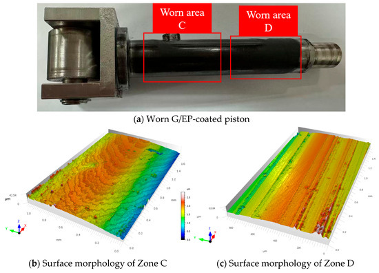
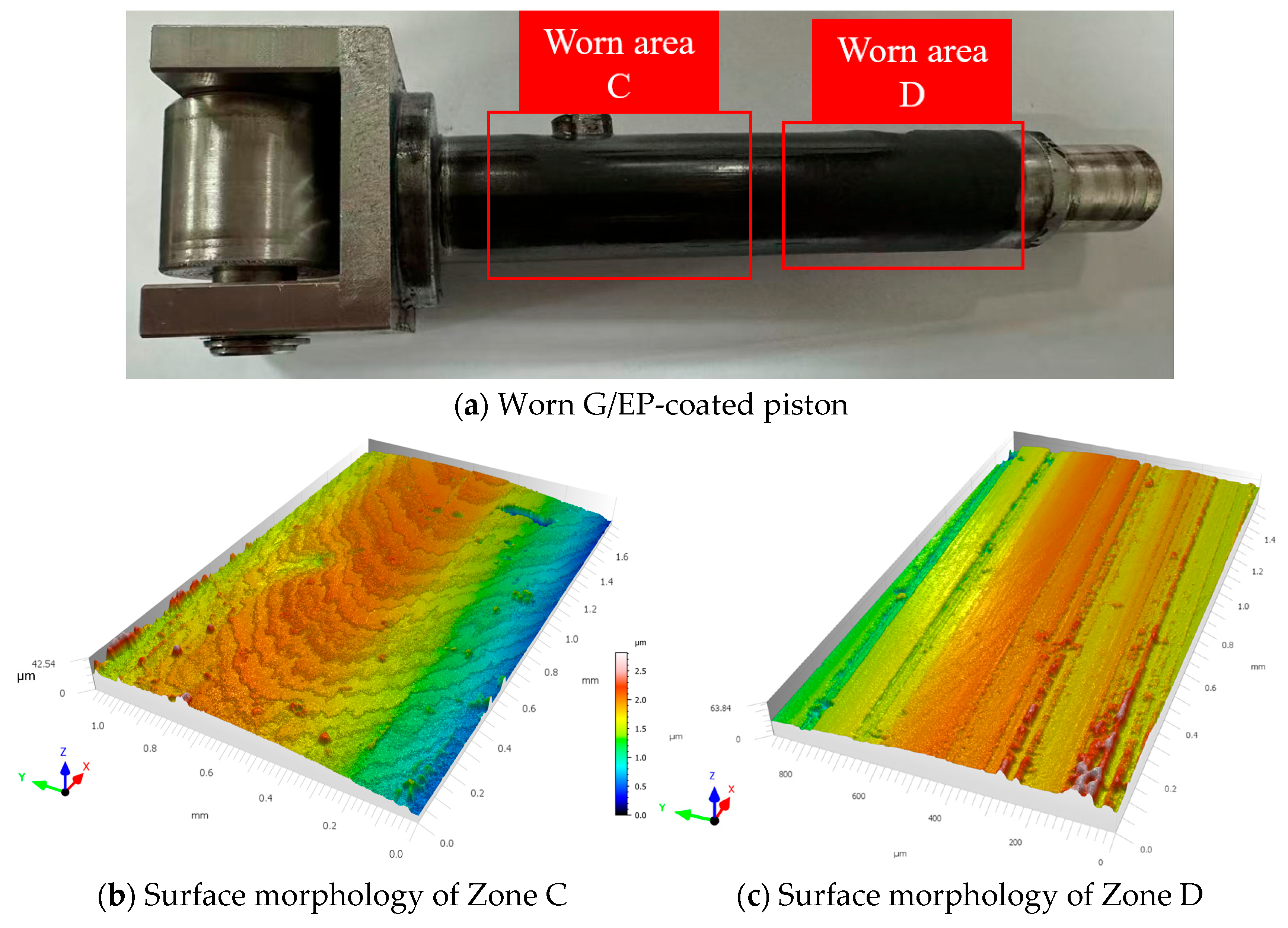
As shown in Figure 21a, Area C corresponds to the mating surface between the G/EP-coated piston rod and the piston cylinder port, where wear marks are significantly mitigated; Area D corresponds to the mating surface between the G/EP-coated piston rod and the linear rolling bearing, where only a few scattered shallow scratches are observed on the coating surface with no obvious spalling. As shown in Figure 21b, for Area C on the surface of the G/EP-coated piston rod, the maximum wear depth is 8.49 μm, the average wear depth is 2.137 μm, and the wear volume per unit area is 2.13 μm3. Compared with Area A on the surface of the uncoated 316L piston rod, the maximum wear depth is reduced by 73.96%, the average wear depth by 57.82%, and the wear volume per unit area by 57.82%, with a more uniform distribution of wear depth across the surface. As shown in Figure 21c, for Area D on the surface of the G/EP-coated piston rod, the maximum wear depth is 6.37 μm, the average wear depth is 1.72 μm, and the wear volume per unit area is 1.72 μm3. Compared with Area B on the surface of the uncoated 316L piston rod, the maximum wear depth is reduced by 70.09%, the average wear depth by 47.72%, and the wear volume per unit area by 47.72%.
Figure 21.
Surface morphology of the worn G/EP-coated piston.
It should be noted that the 10 h sliding test conducted in this study is intended as a proof-of-concept evaluation, aiming to preliminarily assess the feasibility of the coating under realistic water-lubricated operating conditions. The current results demonstrate that the coating possesses favorable friction-reduction and wear-resistance potential over short durations: the worn surface morphology is uniform with no evidence of large-area delamination, indicating good interfacial adhesion between the coating and the substrate; furthermore, no appreciable swelling or peeling is observed after 10 h of water-lubricated sliding, suggesting acceptable short-term water resistance. However, considering that water molecules may progressively compromise interfacial bonding through permeation during prolonged friction, the long-term service performance and potential degradation behavior of the coating require further investigation, as systematic evaluation of water resistance and interfacial durability has not yet been undertaken in this study. Accordingly, extended durability tests spanning up to 500 h will be conducted in subsequent work, during which the evolution of both the friction coefficient and the wear rate will be systematically monitored to provide a more comprehensive assessment of the engineering application prospects of this coating system.
5. Conclusions
This study addresses the tribological challenges of the piston–cylinder pair in water-lubricated radial piston pumps by developing a graphene-modified epoxy resin composite coating. Combined with reciprocating friction tests under simulated pump operating conditions, the surface wettability and tribological properties under water-lubricated conditions were investigated, the application potential of the modified coating was evaluated, and experimental validation was conducted. The main conclusions are as follows:
- (1)
- Tribological test results indicate that compared with 316L stainless steel and pure epoxy coating, both graphene-modified and graphene oxide-modified EP coatings significantly reduce the friction coefficient and wear rate under water-lubricated conditions. Graphene achieves optimal performance at a content of 0.6 wt.%, with a friction coefficient of 0.072, representing a reduction of 81.5% compared with the 316L-316L counterface pair, and a wear rate reduction of 66.57%. Graphene oxide exhibits optimal performance at a content of 0.8 wt.%, with a friction coefficient of 0.089, representing a reduction of 64.4% compared with the 316L-316L counterface pair, and a wear rate reduction of 48.39%.
- (2)
- Wear morphology analysis reveals that the tribological performance of the modified EP coating friction pairs is significantly improved compared with that of the 316L-316L counterface pair. The worn surfaces of both graphene-modified and graphene oxide-modified EP coatings are relatively flat overall, with clear boundaries from the unworn substrate and no evidence of extensive material spalling, demonstrating favorable friction-reducing and anti-wear properties.
- (3)
- Contact angle measurements revealed that the neat epoxy coating exhibited a water contact angle of 60°, which increased to 68° and 70° upon the incorporation of 0.6 wt.% graphene and 0.8 wt.% graphene oxide, respectively. This moderate enhancement in hydrophobicity achieves a favorable balance between water film load-bearing capacity and interfacial adhesion, thereby providing a beneficial interfacial wetting state for water-lubricated operating conditions.
- (4)
- Single-piston pump experiments demonstrate that under cyclic loading and water-lubricated conditions, the G/EP-coated piston rod with a graphene content of 0.6 wt.% achieves a maximum reduction of 57.82% in wear volume per unit area compared with the uncoated 316L piston rod surface. This coating exhibits excellent friction stability and durability, effectively enhancing the tribological performance of the water-lubricated piston–cylinder pair and demonstrating promising potential for engineering applications, thereby providing a viable technical solution for the surface protection of high-performance water-lubricated hydraulic components.
Author Contributions
Conceptualization, X.Z. and Z.Z.; methodology, Z.Z.; software, Y.Z.; validation, J.Z., X.Z. and Z.Z.; formal analysis, J.Z.; investigation, M.Z.; resources, Y.Z.; data curation, Z.Z.; writing—original draft preparation, Z.Z.; writing—review and editing, Z.Z.; visualization, M.Z.; supervision, Y.Z.; project administration, M.Z.; funding acquisition, X.Z. All authors have read and agreed to the published version of the manuscript.
Funding
This research received no external funding.
Data Availability Statement
The data presented in this study are available on request from the corresponding author. The data are not publicly available due to privacy or ethical restrictions.
Acknowledgments
The authors wish to thank all colleagues and staff who contributed to this work through general technical and administrative support.
Conflicts of Interest
The authors declare no conflicts of interest.
References
- Zhang, X.; Zhang, Z.; Zuo, J.; Shi, B.; Fan, X.; Chen, K. Enhancing seawater-lubricated radial piston pump performance via radial auxiliary support. Phys. Fluids 2025, 37, 67118. [Google Scholar] [CrossRef] [Scilit]
- Zhang, Z.; Cao, S.; Wang, H.; Luo, X.; Deng, J.; Zhu, Y. The approach on reducing the pressure pulsation and vibration of seawater piston pump through integrating a group of accumulators. Ocean Eng. 2019, 173, 319–330. [Google Scholar] [CrossRef] [Scilit]
- Liang, Y.; Wang, W.; Zhang, Z.; Xing, H.; Wang, C.; Zhang, Z.; Guan, T.; Gao, D. Effect of Material Selection and Surface Texture on Tribological Properties of Key Friction Pairs in Water Hydraulic Axial Piston Pumps: A Review. Lubricants 2023, 11, 324. [Google Scholar] [CrossRef] [Scilit]
- Liu, Y.; Wu, D.; He, X.; Li, Z. Materials screening of matching pairs in a water hydraulic piston pump. Ind. Lubr. Tribol. 2009, 61, 173–178. [Google Scholar] [CrossRef] [Scilit]
- Li, D.; Ma, X.; Wang, S.; Lu, Y.; Liu, Y. Failure analysis on the loose closure of the slipper ball-socket pair in a water hydraulic axial piston pump. Eng. Fail. Anal. 2024, 155, 107718. [Google Scholar] [CrossRef] [Scilit]
- Jia, H.; Zhou, Z.; Yin, B.; Zhou, H.; Xu, B. Effect of compound texture on lubrication and sealing performance of plunger pump. Lubr. Sci. 2021, 33, 43–59. [Google Scholar] [CrossRef] [Scilit]
- Qi, W.; Wang, X.; Zhou, S. Numerical Simulation of Liquid Film Sealing Performance for a CO2 Plunger Pump Slipper Pair. ACS Omega 2025, 10, 47320–47326. [Google Scholar] [CrossRef] [Scilit]
- Li, Y.; Yu, L.; Jiang, H.; Zhao, E. Transient sealing characteristics of Glyd-ring in the high water-based piston pair under reciprocating pump conditions. Tribol. Int. 2024, 192, 109293. [Google Scholar] [CrossRef] [Scilit]
- Li, D.; Li, G.; Han, J.; Liu, Y.; Wu, D. Thermodynamic characteristics research of a water lubricating axial piston pump. Proc. Inst. Mech. Eng. Part C J. Mech. Eng. Sci. 2020, 234, 3873–3889. [Google Scholar] [CrossRef] [Scilit]
- Nie, S.; He, H.; Ji, H.; Nie, S.; Yan, X.; Yin, F. Failure analysis of auxiliary support bearing/shaft tribopair in seawater hydraulic axial piston pump. Eng. Fail. Anal. 2023, 146, 107069. [Google Scholar] [CrossRef] [Scilit]
- Peter, E.; Zum Gahr, K.H. Lasermodifizierte Al2O3- und ZTA-Keramik für reversierend beanspruchte Gleitkomponenten unter Mangelschmierung. Mater. Werkst. 2004, 35, 809–816. [Google Scholar] [CrossRef] [Scilit]
- Wu, D.; Liu, Y.; Zhao, X.; Li, D.; Ren, X. The Tribological Behaviors of Different Mass Ratio Al2O3-TiO2 Coatings in Water Lubrication Sliding against Si3N4. Tribol. Trans. 2016, 59, 352–362. [Google Scholar] [CrossRef] [Scilit]
- Nie, S.; Lou, F.; Ji, H.; Yin, F. Tribological Performance of CF-PEEK Sliding against 17-4PH Stainless Steel with Various Cermet Coatings for Water Hydraulic Piston Pump Application. Coatings 2019, 9, 436. [Google Scholar] [CrossRef] [Scilit]
- Li, D.; Ma, X.; Wang, S.; Wang, J.; Yang, F.; Liu, Y. The Difference in Tribological Characteristics between CFRPEEK and Stainless Steel under Water Lubrication in Friction Testing Machine and Axial Piston Pump. Lubricants 2023, 11, 158. [Google Scholar] [CrossRef] [Scilit]
- Li, R.; Wei, W.; Liu, H.; Geng, X.; Wang, D.; Ye, J.; Chen, R.; Li, S.; Wang, W.; Wu, H.; et al. Tribological behavior of tribo-pairs in water hydraulic radial piston pumps. Proc. Inst. Mech. Eng. Part L J. Mater. Des. Appl. 2023, 237, 1603–1623. [Google Scholar] [CrossRef] [Scilit]
- Li, R.; Wei, W.; Liu, H.; Geng, X.; Li, J.; Lai, Y.; Chen, R.; Li, D.; Yu, T.; Wang, D.; et al. Evaluation of tribological behavior of tribopairs in water hydraulic radial piston pumps with multiple coatings and lubrication. J. Theor. Appl. Mech. 2024, 62, 841–854. [Google Scholar] [CrossRef] [Scilit] [PubMed]
- Liang, Y.; Xing, H.; Zhang, F.; Chen, N.; Wang, C.; Zhuang, X.; Zhang, Z.; Wang, W.; Gao, D. Effect of two-order composite texture surface on frictional characteristics and wear mechanisms of slipper pairs by CF/PEEK-316L in seawater medium. Proc. Inst. Mech. Eng. Part J J. Eng. Tribol. 2025, 239, 1612–1628. [Google Scholar] [CrossRef] [Scilit]
- Liang, Y.; Wang, H.; Zhang, Z.; Xing, H.; Liang, X.; Li, Y.; Chen, N.; Zhang, F.; Wang, W.; Gao, D. Optimization of bionic surface texture for enhanced tribological performance in seawater axial piston pump slipper pairs via numerical simulation, experiment, and intelligent algorithms. Wear 2026, 591, 206585. [Google Scholar] [CrossRef] [Scilit]
- Loy, X.Z.K.; Sinha, S.K. Lubrication of polyether ether ketone (PEEK) surface by liquid ultrathin films for high wear durability. Wear 2012, 296, 681–692. [Google Scholar] [CrossRef] [Scilit]
- Mohammed, A.S.; Fareed, M.I. Improving the friction and wear of poly-ether-etherketone (PEEK) by using thin nano-composite coatings. Wear 2016, 364, 154–162. [Google Scholar] [CrossRef] [Scilit]
- Guo, L.; Pei, X.; Zhao, F.; Zhang, L.; Li, G.; Zhang, G. Tribofilm growth at sliding interfaces of PEEK composites and steel at low velocities. Tribol. Int. 2020, 151, 106456. [Google Scholar] [CrossRef] [Scilit]
- Nielander, A.C.; Blair, S.J.; McEnaney, J.M.; Schwalbe, J.A.; Adams, T.; Taheri, S.; Wang, L.; Yang, S.; Cargnello, M.; Jaramillo, T.F. Readily Constructed Glass Piston Pump for Gas Recirculation. ACS. Omega 2020, 5, 16455–16459. [Google Scholar] [CrossRef] [Scilit]
- Nie, S.; Guo, M.; Yin, F.; Ji, H.; Ma, Z.; Hu, Z.; Zhou, X. Research on fluid-structure interaction for piston/cylinder tribopair of seawater hydraulic axial piston pump in deep-sea environment. Ocean. Eng. 2021, 219, 108222. [Google Scholar] [CrossRef] [Scilit]
- Jin, F.; Li, X.; Park, S. Synthesis and application of epoxy resins: A review. J. Ind. Eng. Chem. 2015, 29, 1–11. [Google Scholar] [CrossRef] [Scilit]
- Li, D.; Wang, H.; Liu, Y.; Wei, D.-S.; Zhao, Z.-X. Large-scale fabrication of durable and robust super-hydrophobic spray coatings with excellent repairable and anti-corrosion performance. Chem. Eng. J. 2019, 367, 169–179. [Google Scholar] [CrossRef] [Scilit]
- Montemor, M.F. Functional and smart coatings for corrosion protection: A review of recent advances. Surf. Coat. Technol. 2014, 258, 17–37. [Google Scholar] [CrossRef] [Scilit]
- Fuseini, M.; Zaghloul, M.M.Y.; Abakar, D.; Zaghloul, M.M.Y. Review of epoxy nano-filled hybrid nanocomposite coatings for tribological applications. FlatChem 2025, 49, 100768. [Google Scholar] [CrossRef] [Scilit]
- Dorri Moghadam, A.; Omrani, E.; Menezes, P.L.; Rohatgi, P.K. Mechanical and tribological properties of self-lubricating metal matrix nanocomposites reinforced by carbon nanotubes (CNTs) and graphene—A review. Compos. Part B Eng. 2015, 77, 402–420. [Google Scholar] [CrossRef] [Scilit]
- Liu, S.; Chevali, V.S.; Xu, Z.; Hui, D.; Wang, H. A review of extending performance of epoxy resins using carbon nanomaterials. Compos. Part B Eng. 2018, 136, 197–214. [Google Scholar] [CrossRef] [Scilit]
- Barletta, M.; Vesco, S.; Puopolo, M.; Tagliaferri, V. High performance composite coatings on plastics: UV-curable cycloaliphatic epoxy resins reinforced by graphene or graphene derivatives. Surf. Coat. Technol. 2015, 272, 322–336. [Google Scholar] [CrossRef] [Scilit]
- Shen, X.; Pei, X.; Fu, S.; Friedrich, K. Significantly modified tribological performance of epoxy nanocomposites at very low graphene oxide content. Polymer 2013, 54, 1234–1242. [Google Scholar] [CrossRef] [Scilit]
- Düzcükoğlu, H.; Ekinci, Ş.; Şahin, Ö.S.; Avci, A.; Ekrem, M.; Ünaldi, M. Enhancement of Wear and Friction Characteristics of Epoxy Resin by Multiwalled Carbon Nanotube and Boron Nitride Nanoparticles. Tribol. Trans. 2015, 58, 635–642. [Google Scholar] [CrossRef] [Scilit]
- Wu, X.; Wyman, I.; Zhang, G.; Lin, J.; Liu, Z.; Wang, Y.; Hu, H. Preparation of superamphiphobic polymer-based coatings via spray- and dip-coating strategies. Prog. Org. Coat. 2016, 90, 463–471. [Google Scholar] [CrossRef] [Scilit]
- Perna, A.S.; Astarita, A.; Carlone, P.; Guthmann, X.; Viscusi, A. Characterization of Cold-Spray Coatings on Fiber-Reinforced Polymers through Nanoindentation Tests. Metals 2021, 11, 331. [Google Scholar] [CrossRef] [Scilit]
- Bao, T.; Wang, Z.; Zhao, Y.; Wang, Y.; Yi, X. Improving tribological performance of epoxy composite by reinforcing with polyetheramine-functionalized graphene oxide. J. Mater. Res. Technol. 2021, 12, 1516–1529. [Google Scholar] [CrossRef] [Scilit]
- Zhao, B.; Bai, T. Improving the tribological performance of epoxy coatings by the synergistic effect between dehydrated ethylenediamine modified graphene and polytetrafluoroethylene. Carbon 2019, 144, 481–491. [Google Scholar] [CrossRef] [Scilit]
- Xia, H.; Li, J.; Wang, K.; Hou, X.; Yang, T.; Hu, J.; Shi, Z. Superior wear resistance of epoxy composite with highly dispersed graphene spheres. Adv. Compos. Hybrid Mater. 2022, 5, 173–183. [Google Scholar] [CrossRef] [Scilit]
- Hao, Q.; Liu, S.; Wang, X.; Zhang, P.; Mao, Z.; Zhang, X. Progression from graphene and graphene oxide to high-performance epoxy resin-based composite. Polym. Degrad. Stabil. 2024, 223, 110731. [Google Scholar] [CrossRef] [Scilit]
- Li, L.; Wang, J.; Pei, X.; Chu, W.; Cai, A. A modified elastic contact stiffness model considering the deformation of bulk substrate. J. Mech. Sci. Technol. 2020, 34, 777–790. [Google Scholar] [CrossRef] [Scilit]
- Fan, J.; Anastassiou, A.; Macosko, C.W.; Tadmor, E.B. Molecular Dynamics-Based Cohesive Law for Epoxy–Graphene Interfaces. Tribol. Lett. 2021, 69, 55. [Google Scholar] [CrossRef] [Scilit]
- Li, W.; Chai, W.; Zhang, L.; Guo, Y.; Wang, W.; Chen, S. Atomic insight into the influences of moisture ingress on the structures and dynamics of graphene-epoxy interfaces. Compos. Sci. Technol. 2022, 219, 109222. [Google Scholar] [CrossRef] [Scilit]
- Ding, Y.M.; Wang, J.Q.; An, Y.; Shao, J.B.; Ma, K.; Zhang, Y.C. Study on the Influences of Ultrasonic Conditions on the Dispersion of Multi-Walled Carbon Nanotubes in Reinforced Epoxy. Key Eng. Mater. 2013, 561, 47–53. [Google Scholar] [CrossRef] [Scilit]
- Zhang, M.; Chen, P.; Wang, G.; Dai, T.; Sun, P. Preparation of liquid-infused surface on epoxy resin for improved tribological and anti-corrosion performance. Colloids Surf. A Physicochem. Eng. Asp. 2023, 668, 131472. [Google Scholar] [CrossRef] [Scilit]
- Standard’s ISO 2808:2019; Paints and Varnishes — Determination of Film Thickness. International Organization for Standardization: Geneva, Switzerland, 2019.

Disclaimer/Publisher’s Note: The statements, opinions and data contained in all publications are solely those of the individual author(s) and contributor(s) and not of MDPI and/or the editor(s). MDPI and/or the editor(s) disclaim responsibility for any injury to people or property resulting from any ideas, methods, instructions or products referred to in the content. |
© 2026 by the authors. Licensee MDPI, Basel, Switzerland. This article is an open access article distributed under the terms and conditions of the Creative Commons Attribution (CC BY) license.