


Abstract
This study investigates the non-Newtonian effects on liquid film seal performance by considering cavitation and thermoelastic deformation—critical factors in high-pressure sealing applications such as nuclear reactor coolant pumps and aerospace systems. We developed a coupled numerical model that simultaneously solves the Reynolds equation using a power-law constitutive model to analyze hydrodynamic performance and employs the energy equation and thermal-structural analysis to determine the temperature distribution and radial taper deformation of the seal rings. The results reveal that the power-law exponent (n) critically influences sealing behavior: shear-thinning fluids (n < 1) reduce the load capacity by 12.7% due to expanded cavitation zones, whereas shear-thickening fluids (n > 1) increase the friction torque by 18.3% through thermally-induced tapered convergence effects. We established quantitative relationships between rheological properties, thermal deformation, and sealing performance, demonstrating that non-Newtonian characteristics fundamentally alter the fluid–structure interaction mechanisms in liquid-film seals. These findings provide a theoretical foundation for optimizing seal designs under extreme operating conditions where conventional Newtonian assumptions prove inadequate, particularly addressing the critical need for enhanced reliability in nuclear and aerospace sealing systems.
1. Introduction
Due to their low abrasion, low leakage, and low power consumption, mechanical liquid film seals have been widely used in rotating machinery, such as in chemical engineering and energy systems [1,2]. To improve lubrication conditions, various groove patterns are machined on the surface of either the rotating or stationary rings [3,4,5]. Thanks to the combined hydrostatic and hydrodynamic effects generated by their grooves, these face seals can operate without contact [6]. Several machining methods—including laser texturing, pulse air arc treatment, electro-polishing [7], and a novel high-speed scratching technique [8,9]—have been employed to fabricate surface textures. Owing to their excellent hydrodynamic performance, spiral-groove face seals are among the most typical and widely used shallow-groove face seals [10].
A mechanical liquid film seal is a key component commonly used in rotating equipment—ranging from washing machines to rocket engines—both to prevent hydraulic fluid from leaking into the environment and to ensure the reliable performance of the hydraulic system [11,12,13]. Adding long-chain polymer additives to the lubricant can reduce the friction coefficient of the surfaces, as well as heat generation and wear, leading to better lubrication performance [14,15]. However, these additives cause the lubricant to exhibit non-Newtonian flow characteristics. In fact, the non-Newtonian effect of the liquid film is an important factor in improving lubrication and reducing friction and wear, especially in mechanical seals under heavy load and high-speed conditions [16]. Compared with Newtonian fluids, non-Newtonian fluids exhibit nonlinear stress–strain relationships under liquid film conditions. In practical applications, many sealing media show non-Newtonian lubrication characteristics, particularly in aero-engines, nuclear coolant pumps, and other rotating equipment operating under extreme conditions [17,18]. To numerically simulate such lubrication phenomena, a Reynolds equation incorporating relevant non-Newtonian constitutive equations—derived from the simplified Navier–Stokes equation and the continuity equation—was derived. Excessively high temperatures of the liquid film or seal rings, caused by energy dissipation, are an important factor leading to seal failure. High temperature can cause deformation of the seal rings and degradation of lubrication, which can ultimately result in seal failure. Describing the nonlinear relationship between the shear stress and the shear rate is key to simulating the lubricant behavior within the liquid film.
Considerable research has been conducted to investigate the non-Newtonian behavior and its effect on seal performance. However, few studies have considered both non-Newtonian and thermal effects simultaneously. In this paper, a mathematical model that accounts for both non-Newtonian and thermal effects is established. The governing equations are discretized using the finite difference method to calculate the pressure and temperature of the liquid film, the thermo-mechanical deformation of the seal rings, and the resulting sealing performance. Lubricating fluids with different power-law exponents are used in the numerical simulation. The effects of operating conditions—including pressure and rotational speed—and groove parameters—such as groove number and groove depth—are investigated in this study.
2. Mathematical Model
2.1. Structure Model
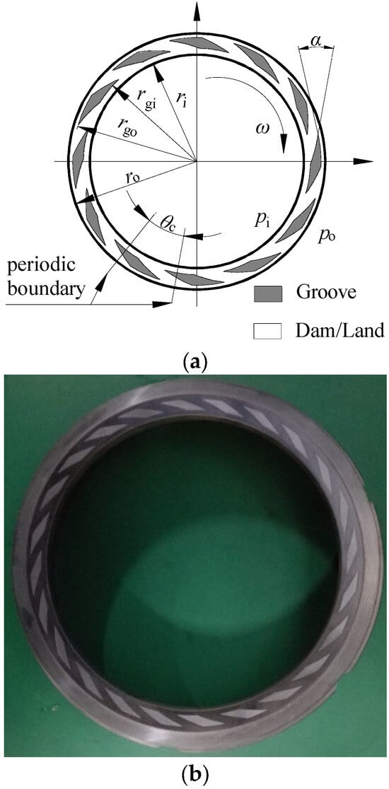
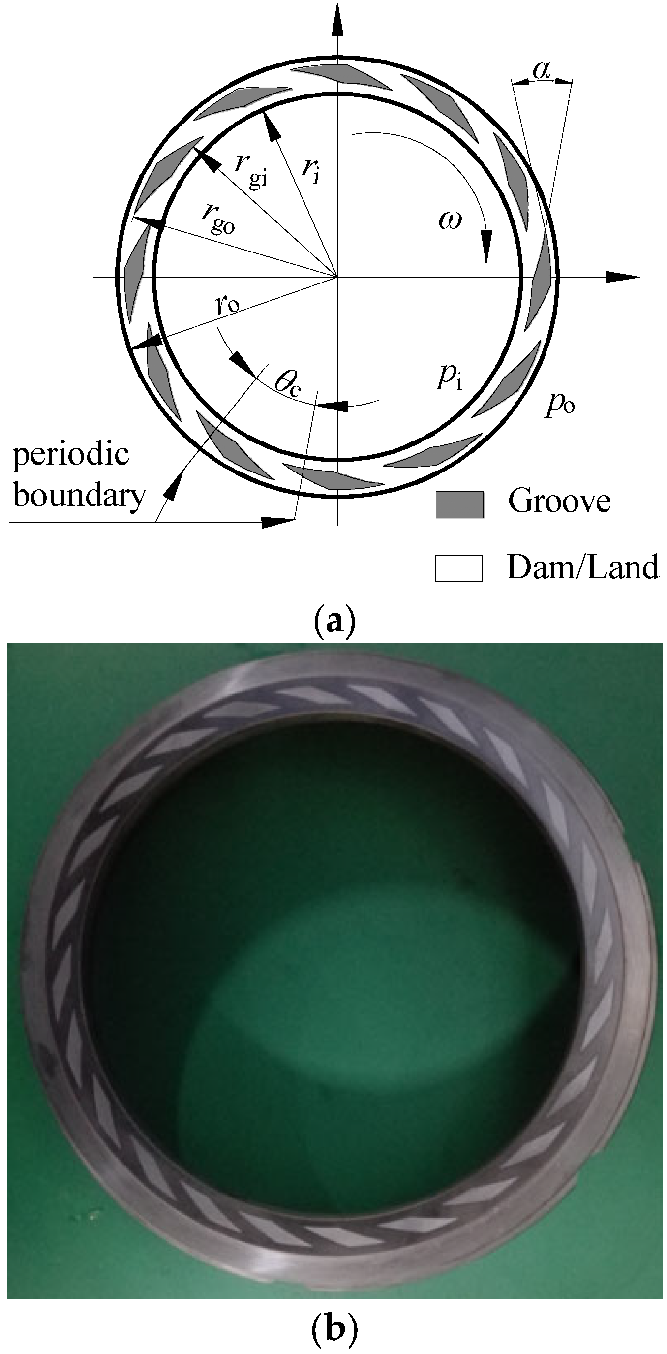
The groove structure of the friction pair is illustrated in Figure 1. The grooves are distributed on the rotating ring, while the stationary ring is groove-free. A hydrodynamic effect is generated by the spiral grooves as the rotating ring rotates at a speed ω. A hydrostatic effect is present in both the groove and dam areas. The combination of hydrostatic and hydrodynamic effects enables the seal rings to operate without contact. Fluid enters the gap between the stator and rotor, providing lubrication.
Figure 1.
Structure diagram of groove. (a) Diagram of rotating ring; (b) rotating ring.
In Figure 1, ri and ro denote the inner and outer radii of the sealing face, while rg1 and rg2 are the inner and outer radii of the spiral groove. The spiral angle is represented by α, and θc represents the circumferential angles of the groove and land. The inner and outer pressures are denoted by pi and po, respectively. The geometric parameters and operating conditions are summarized in Table 1.
Table 1.
Structure and condition parameters spiral groove.
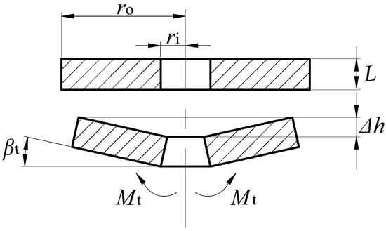
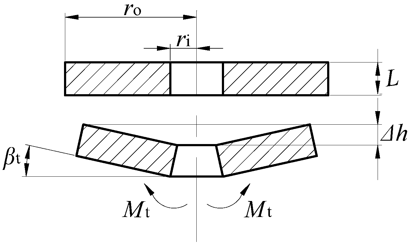
In Figure 2, ri and ro are the inner and outer radii of the sealing face. rg1 and rg2 are the inner and outer radii of the spiral groove. α represents the spiral angle. θc represents the circumferential angles of the groove and land. pi and po are the inner and outer pressures. The values of the geometric parameters and the conditions are shown in Table 1. The value of the liquid properties is shown in Table 2. Ng is the number of grooves. 40# lubricating oil was used in the experiment.
Figure 2.
Deformation of radial taper.
Table 2.
Fluid property parameters.
2.2. Governing Equations
The calculation is simplified by the assumptions: (1) The lubrication is a power-law fluid [19] and its flow is laminar, non-inertial and incompressible, (2) the angular misalignment of the friction pair and the fluid inertial are neglected, (3) the waviness of the seal ring surface is neglected, (4) the pressure and temperature of the liquid film do not change in the direction of film thickness, and (5) the velocity of the fluid is the same as the solid on interface.
Based on the assumptions, the N-S equation can be simplified:
For a power-law model fluid, the rheological equation, which describes the nonlinear relationship between shear stress and shear rate, is defined as follows [9]:
In Equation (1), is the shear rate (in s−1), τzx is the shear stress (in Pa), m is the consistency coefficient (in Pa·sn), u is the apparent viscosity (in Pa·s), and n is the power-law index (dimensionless). A Newtonian fluid has n = 1, a pseudoplastic fluid has n < 1, and a dilatant fluid has n > 1.
The velocity boundary conditions:
Equation (1) is integrated in the z direction:
The continuity equation integrated in the z direction:
Inserting Equations (3) and (5) into Equation (6), the non-Newtonian fluid Reynolds equation in polar coordinates can be written as:
When the pressure drops below the critical pressure at the ambient temperature, cavitation occurs in the liquid film. The liquid film is divided into a full liquid film and a cavitation region. ρ is the density of the full liquid film (in kg/m3), and ρc is the density of the cavitation region (in kg/m3). To describe the liquid cavitation behavior, the JFO boundary condition is adopted. Based on References [20,21,22], in the predictive calculation of the cavitation zone for liquid-lubricated mechanical seals, the JFO model demonstrates higher accuracy and better computational convergence when compared with experimental cavitation results. The switch function g and the general variable ϕ are defined [23] as follows:
According to Equations (8) and (9), the pressure of a liquid film can be defined as:
The Reynolds equation for a power-law model [22,24] fluid considering cavitation is defined as:
In the process of heat dissipation into a liquid film, convection and conduction are the modes of action. To indicate the main heat dissipation, a Peclet number Pe is introduced and defined as:
In (12), k is the heat conductivity (in W/(m·K)), ρ is the density of fluid (in kg/m3), c is the specific heat capacity of liquid (in J/(kg·K)), h is the thickness of liquid film (in m), B is the flow length of the liquid (in m), and VL is the liner velocity of liquid flow (in m/s).
In a coupled surface, the energy generated in z is equal to the conduction from the liquid film to the seal rings. According to Reference [25], the Peclet number (Pe) represents the ratio of conductive heat transfer to convective heat transfer. In an idealized scenario, an infinite Pe indicates that heat dissipation occurs entirely via conduction, whereas a Pe of zero implies pure convection. Empirically, convective heat transfer dominates within the lubricating film when Pe ≤ 0.1, while conduction becomes dominant when Pe ≥ 0.4. In the context of liquid-lubricated mechanical seals, the axial film thickness is extremely small—typically three orders of magnitude less than the radial dimension—and the flow velocity is relatively high. Consequently, the Pe of the lubricating film far exceeds 0.4. Therefore, heat transfer within the sealing interface is predominantly conductive, and convective heat dissipation can reasonably be neglected. That means thermal conduction is the main heat dissipation method, the energy equation of liquid film is considered non-Newtonian, and cavitation can be simplified and defined in polar coordinates:
At the interface between the seal gap, the heat balance equation is defined as:
The temperature and heat distribution can be seen as invariant when the seal system operation is stable. The heat transfer can be simplified with no variance in the circumference and shows axisymmetric distribution; the heat-conduction equation is simplified as:
In Equations (13)–(15), H is the convective heat transfer coefficient (in W/(m2·K)), k1 and k2 are the coefficients of heat conductivity of the rotating ring and the stationary ring (in W/(m·K)), and T1, T2 are the temperatures of the rotating ring and the stationary ring (in K or °C).
Because of the axisymmetry of heat distribution in the seal rings, a two-dimensional ring section is used to calculate the deformation. Taper deformation of the seal rings βd is introduced to estimate the deformation and is defined as:
In Equation (16), rc is the equivalent radius of the seal ring (in m), as is the cross-sectional area (in m2), κ is the linear expansion coefficient (in K−1), Jx is the axial moment of inertia of the seal ring (in m4), and Jxy is the product of inertia (in m4).
3. Results
3.1. Model Verification
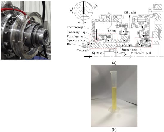
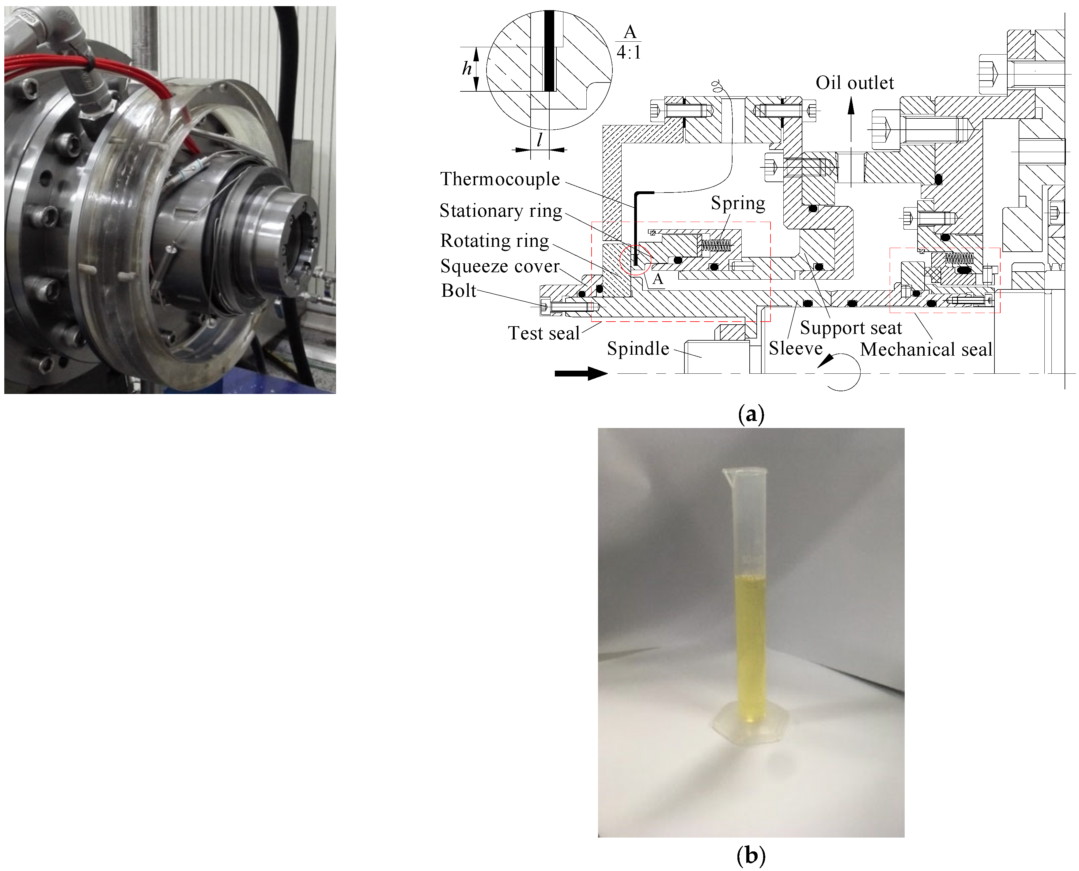
To verify the accuracy of the simulation method, a leak test experiment for the spiral groove was carried out. Figure 3a shows the internal cavity structure of the experimental equipment (Machine Shop, China University of Petroleum (East China), Qingdao, China), and Figure 3b shows the medium used in the experiment. During the operation process, pi = 0.4 MPa, po = 0.1 MPa, and the properties of the medium are shown in Table 2.
Figure 3.
Experimental equipment. (a) Internal cavity structure; (b) 40# oil.
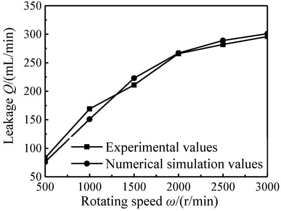
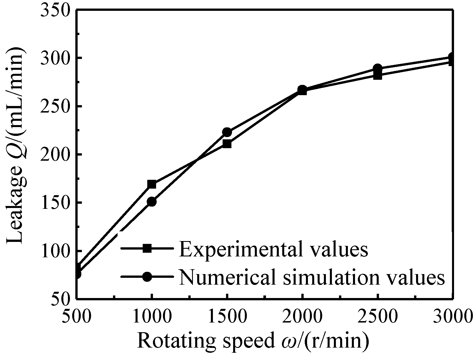
Figure 4 shows a comparison of the leakage obtained from the numerical simulation and the experiment at different rotational speeds. As shown in Figure 4, the error between simulation and experiment is acceptable, and the leakage trends of the two curves are similar. The accuracy of the simulation meets the requirement. The experimental leakage data presented in the figure are the average values obtained from three repeated tests.
Figure 4.
Comparison of numerical simulation and experimental values of leakage.
3.2. Temperature of Liquid Film
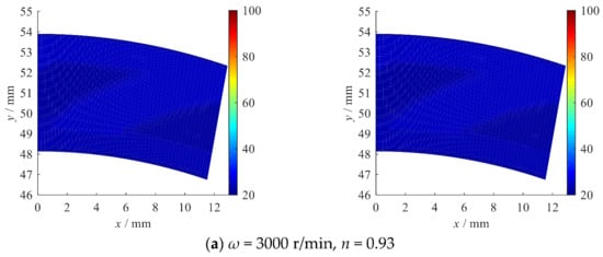
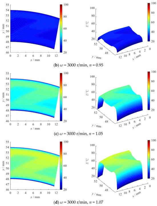
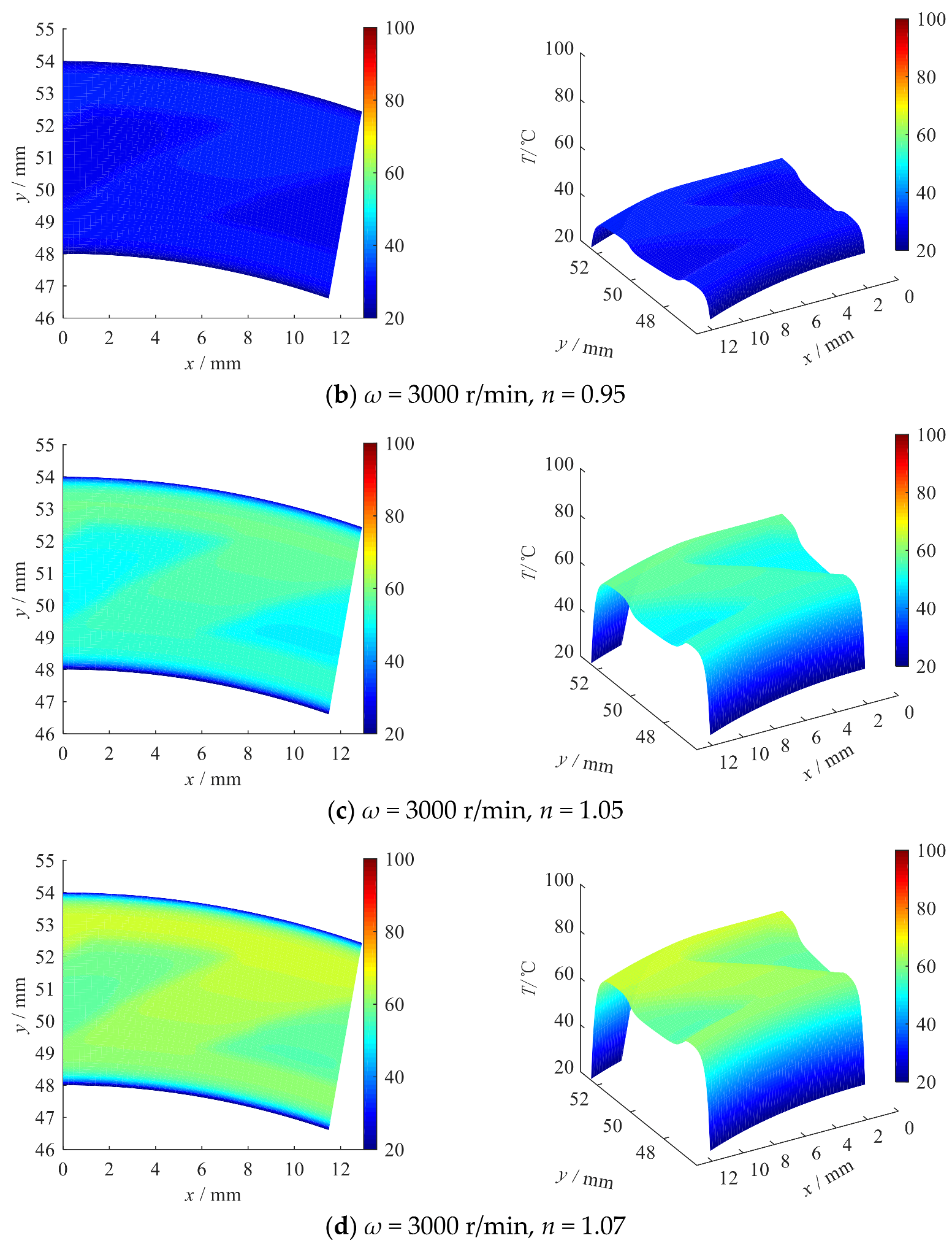
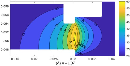
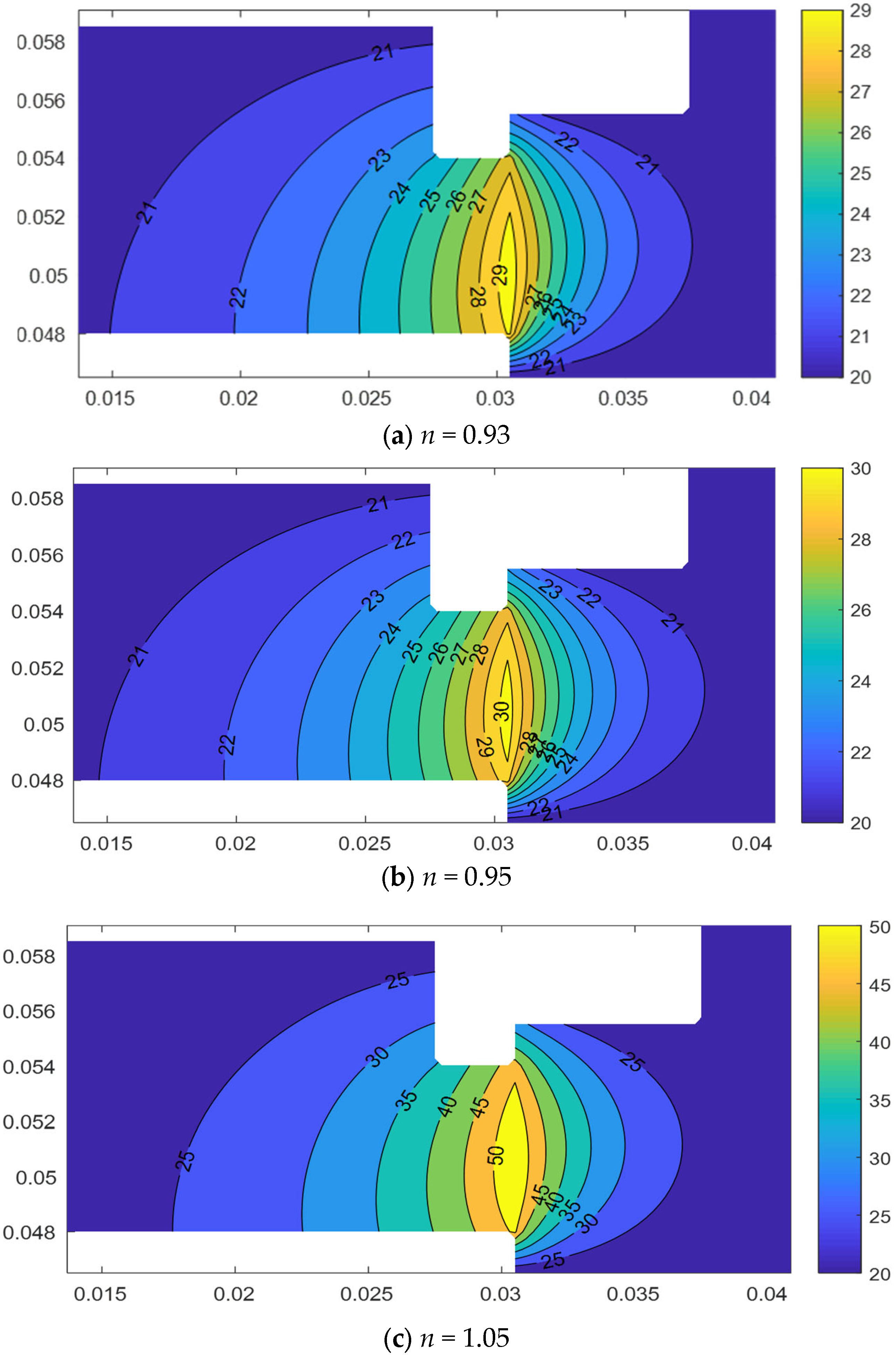
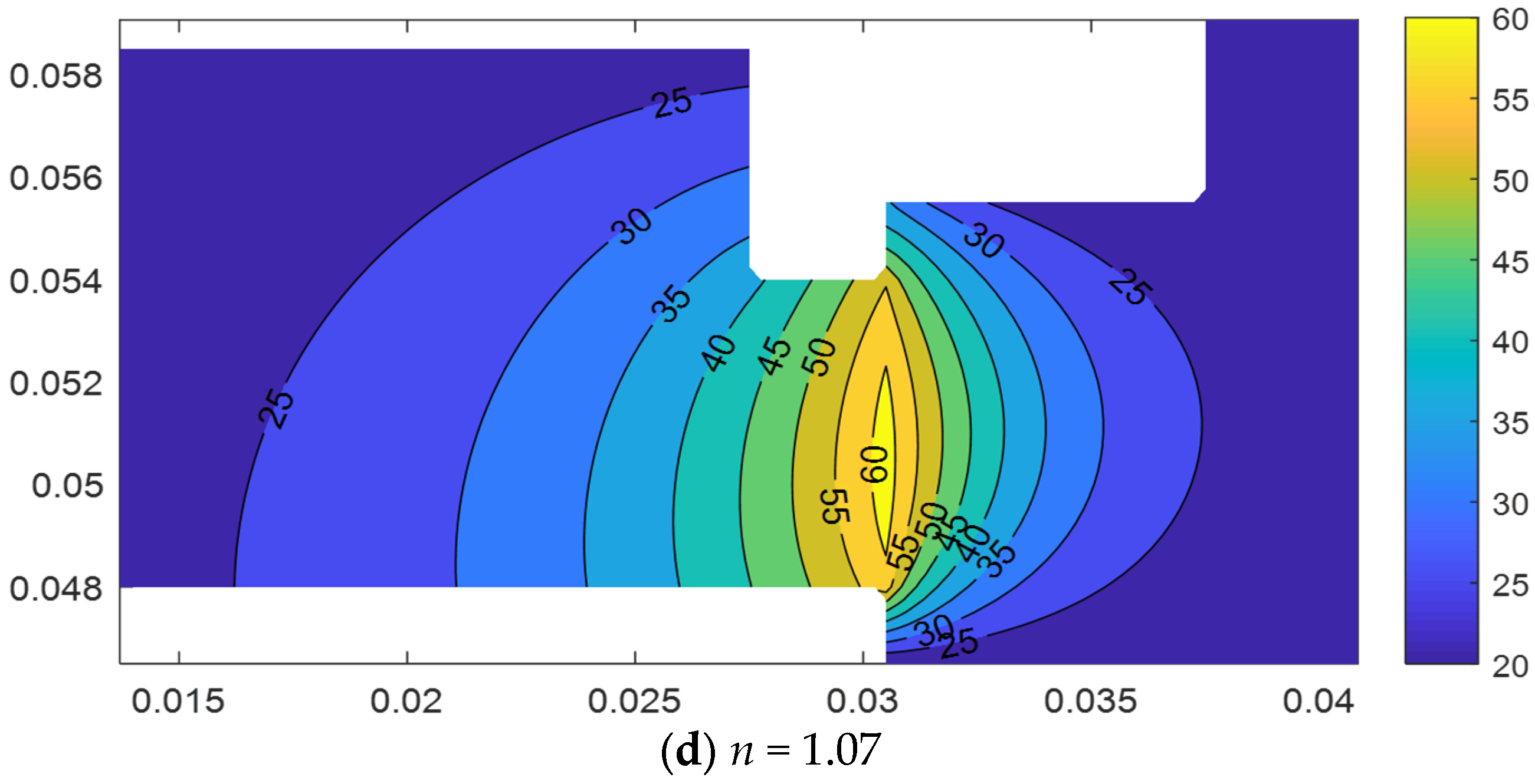
Figure 5 shows the temperature of the liquid film with n = 0.93, n = 0.95, n = 1.05 and n = 1.07 in the spiral groove.
Figure 5.
Temperature of liquid film.
As shown in Figure 5, the temperature distribution of the liquid film is similar across cases; the temperature in the dam is higher than that in the groove. The larger film thickness in the groove provides better heat transfer, which makes the temperature distribution more uniform. The temperature increases as n increases at the same rotational speed. Compared with the pseudoplastic fluid (n < 1), the temperature of the dilatant fluid (n > 1) is affected more significantly by n. The shear viscosity of the fluid with n > 1 is higher, which generates more heat and results in a higher temperature. At the same time, the higher liquid temperature leads to greater radial taper deformation, which further increases friction and temperature. This phenomenon is more pronounced when n is larger and the temperature is higher. The temperature at the inner diameter is higher than that at the outer diameter, a trend that is more obvious for n > 1.
3.3. Temperature of Seal Rings
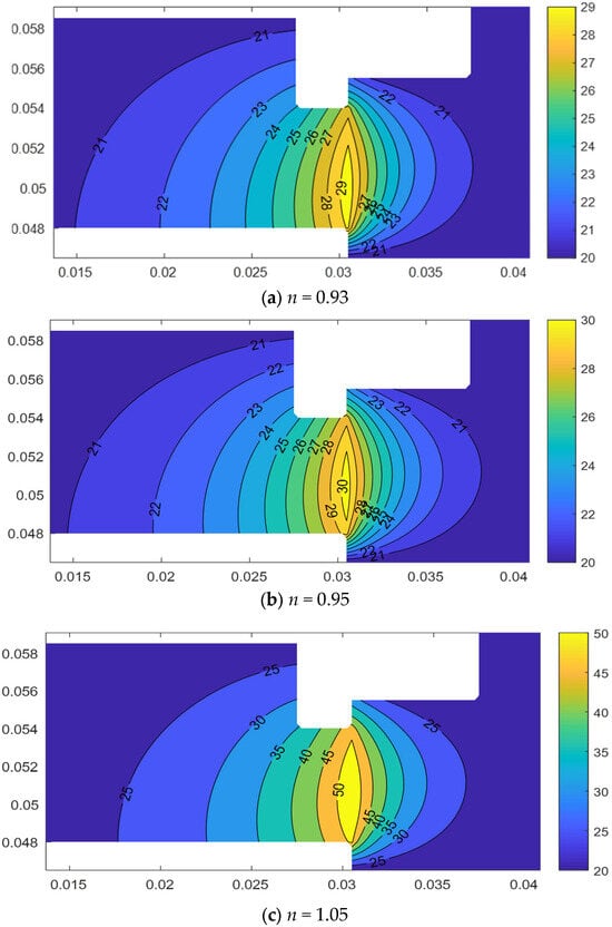
Figure 6 shows the temperature of the seal rings in the fluid medium with n = 0.93, n = 0.95, n = 1.05, and n = 1.07, respectively. Based on the law of energy conservation combined with the properties of heat transfer, the temperature of the friction pair at ω = 3000 r/min, pi = 0.4 MPa, po = 0.1 MPa, was calculated. The properties of the sealing ring are listed in Table 3.
Figure 6.
Temperature of seal rings.
Table 3.
Properties of seal rings.
As shown in Figure 6, the overall temperature of the seal rings increases with increasing n. The peak temperature occurs at the interface between the rotating ring and the stationary ring. Due to the better convective heat transfer conditions on the outer diameter, the convective heat transfer coefficient at the outer diameter is higher than that at the inner diameter, which makes the temperature on the outer side slightly higher. The taper deformation leads to a decrease in the clearance near the outer diameter of the seal ring, which aggravates the wear of the seal face, resulting in a rapid rise in the liquid film temperature at the outer diameter. Meanwhile, the increase in the liquid film temperature further promotes the taper deformation, and the two factors reinforce each other.
3.4. Operation Conditions
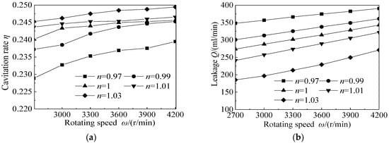
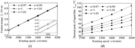
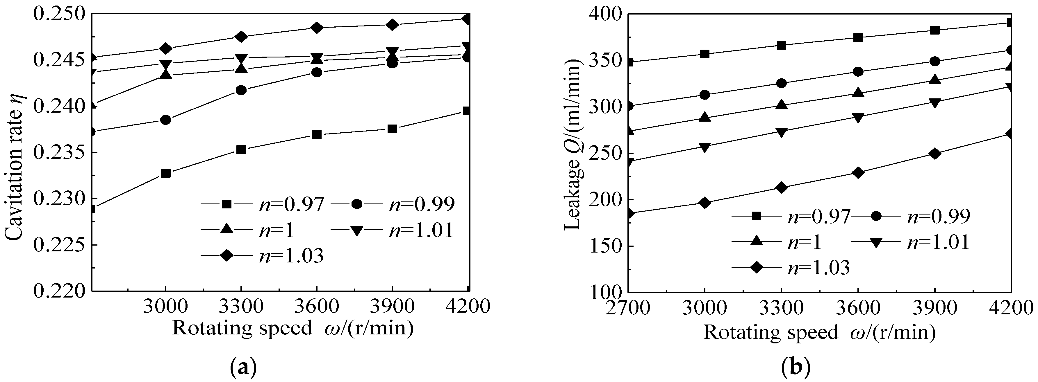
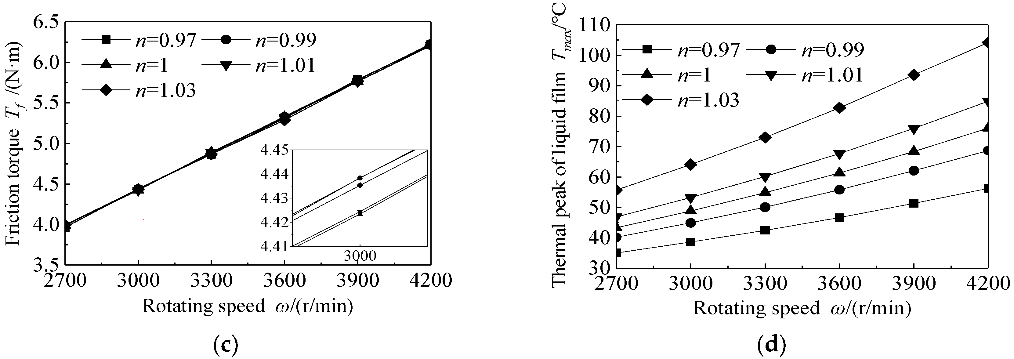
Figure 7 shows the changes in sealing performance parameters—including cavitation ratio, leakage, friction torque, the thermal peak of the liquid film and radial taper— as ω increases from 2700 r/min to 4200 r/min. The pi = 0.4 MPa, po = 0.1 MPa.
Figure 7.
Influence of rotating speed on seal performance. (a) Cavitation rate; (b) leakage; (c) friction torque; (d) thermal peak of liquid film.
Figure 7a shows that the cavitation rate η increases as ω increases with different n. At the same speed, the cavitation rate increases as n increases. The property of shear-thickening accelerates the occurrence of cavitation in the liquid film. As shown in Figure 7b, Q increases as n decreases at the same ω. Figure 7c indicates a small difference in Tf among different n, but shear-thinning and shear-thickening can increase Tf. According to Figure 7d, more heat is generated in the liquid film as the ω increases, which results in the increase in Tmax.
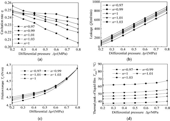
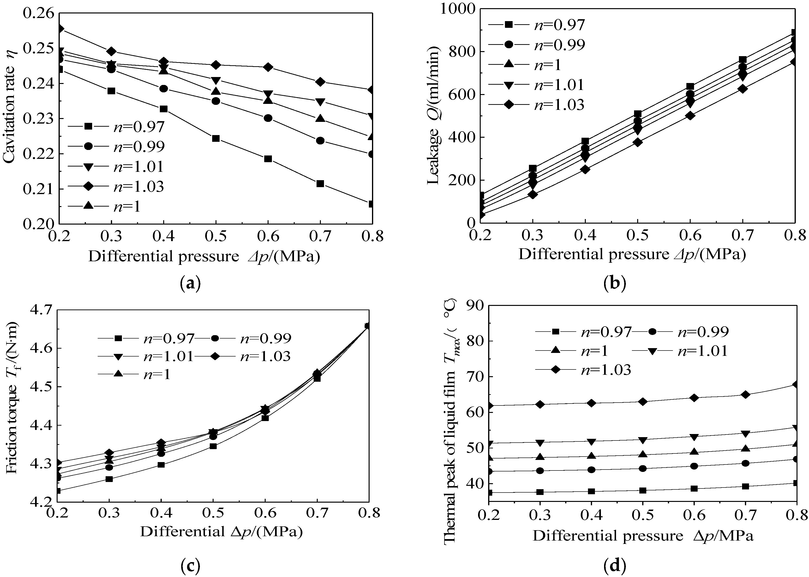
Figure 8 shows the changes in sealing performance parameters for Δp ranging from 0.4 MPa to 0.8 MPa and ω = 3000 r/min.
Figure 8.
Influence of differential pressure on seal performance. (a) Cavitation rate; (b) leakage; (c) friction torque; (d) thermal peak of liquid film.
Figure 8a shows that the cavitation rate η decreases as Δp increases for different n. At the same pressure, the cavitation rate increases as n increases. The liquid film exhibits a higher cavitation rate with a larger n. As shown in Figure 8b, Q decreases as n decreases at the same Δp. Figure 8c indicates that Tf increases as Δp increases. The difference in Tf among different n decreases as Δp increases. When Δp > 0.8 MPa, the difference in Tf can be ignored. The liquid film with a larger n exhibits a higher temperature level, which is caused by the increase in Tf. According to Figure 8d, the thermal peak of the liquid film, Tmax, increases as Δp increases. However, the growth of Tmax is small, which results from the fact that the increasing leakage reduces heat generation to a certain extent.
3.5. Groove Parameters
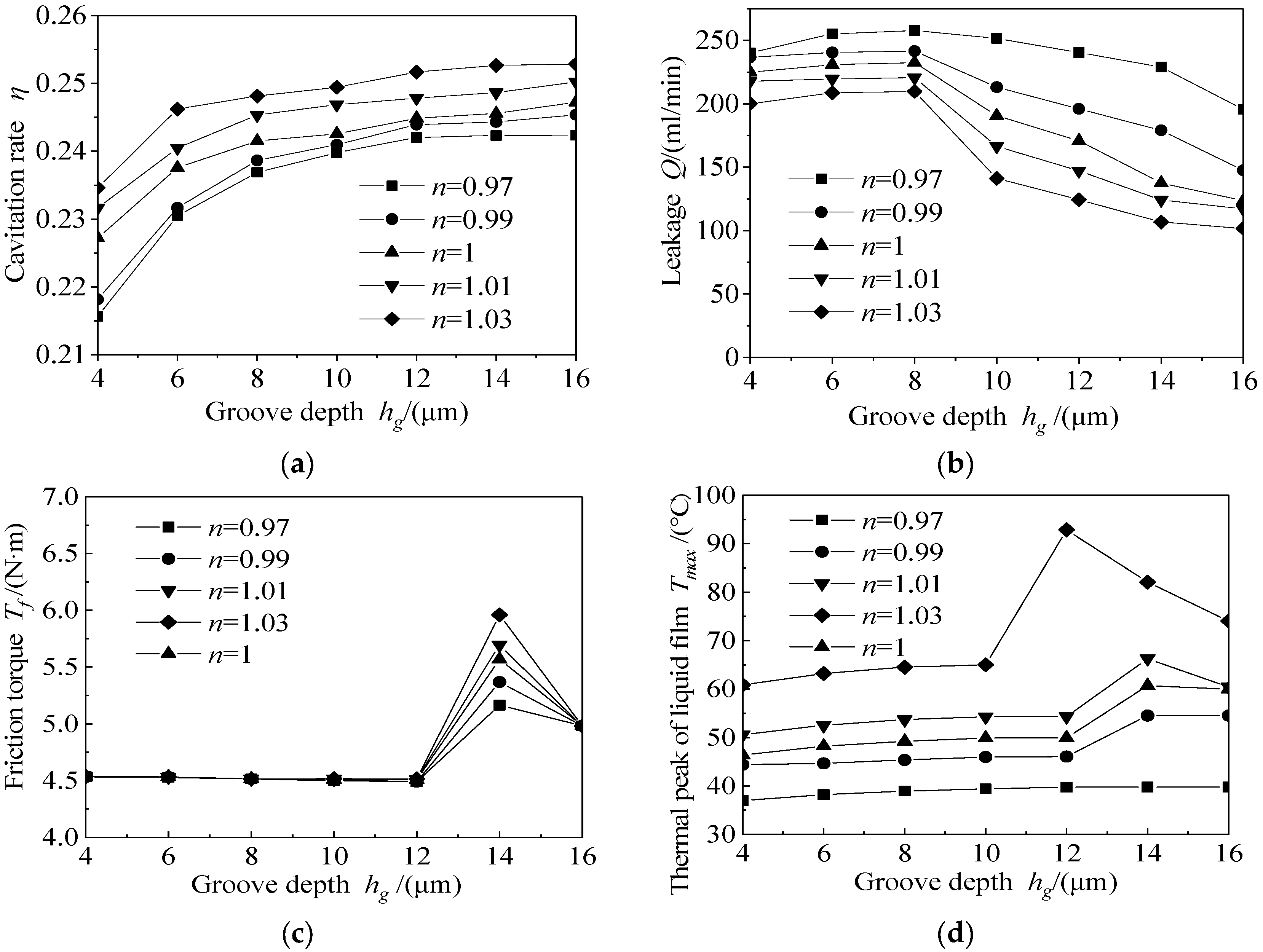
Figure 9 shows the changes in sealing performance parameters with the groove depth hg from 4 μm to 16 μm.
Figure 9.
Influence of groove depth on seal performance. (a) Cavitation rate; (b) leakage; (c) friction torque; (d) thermal peak of liquid film.
Figure 9a shows that the cavitation rate η increases as hg increases for different n. The growth rate slows gradually as hg increases. Increasing the groove depth enhances the hydrodynamic effect of the liquid film to a certain extent. The strengthening effect weakens gradually when hg is above a certain value. According to Figure 9b, for 4 < hg < 8 μm, Q increases as hg increases; for hg > 8 μm, Q decreases as hg increases. As shown in Figure 9c, for 4 < hg < 12 μm, the changes in Tf are negligible; for 12 < hg < 14 μm, Tf increases as hg increases; and for hg > 14 μm, Tf decreases as hg increases. As shown in Figure 9d, Tmax first increases and then decreases as hg increases. Increasing hg enhances the hydrodynamic effect, which thickens the liquid film to maintain the balance of the seal. However, the enhanced effect weakens as hg increases, and combined with the new equilibrium of the liquid film, fluctuations in Q, Tf, and Tmax occur. For the fluid with a larger n, the fluctuation amplitudes of Tf and Tmax are larger.
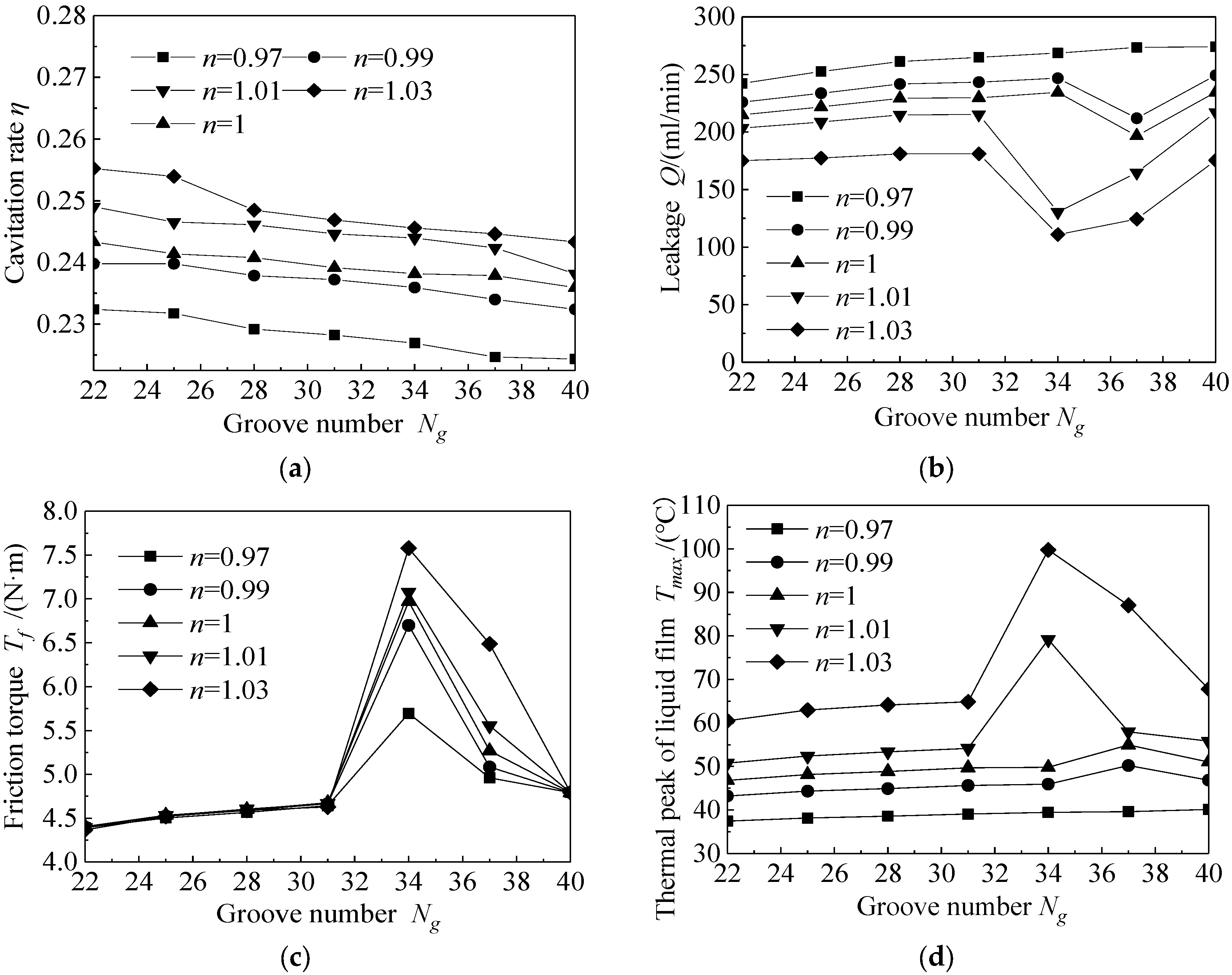
Figure 10 shows the changes in sealing performance parameters with the groove number Ng from 22 to 40.
Figure 10.
Influence of groove number on seal performance. (a) Cavitation rate; (b) leakage; (c) friction torque; (d) thermal peak of liquid film.
Figure 10a shows that the cavitation rate η decreases as Ng increases for different n. Within the range of Ng examined in this study, the hydrodynamic effect of the liquid film diminishes as Ng increases. The liquid film thickness decreases to maintain the pressure equilibrium. This reconfiguration of equilibrium causes fluctuations in Q, Tf, and Tmax. This indicates that the changes in seal performance are undulatory rather than linear with the groove number. According to Figure 10b, for 31 < Ng < 40, Q first decreases and then increases as Ng increases. As shown in Figure 10c,d, for 31 < Ng < 40, Tf and Tmax first increase and then decrease as Ng increases. In this study, the range 31 < Ng < 40 is where these variations occur. The fluctuations are more pronounced when the fluid exhibits shear-thickening properties.
4. Conclusions
The non-Newtonian effect on liquid film seal performance and seal rings considering the thermal effect is investigated. Then, based on the results, the influence of operating conditions and groove structure on seal performance is studied. The main conclusions are as follows:
- (1)
- Compared with the pseudoplastic fluid, the non-Newtonian effect has a greater influence on the temperature and deformation of the dilatant fluid.
- (2)
- Higher liquid temperature results in a larger radial taper, which accelerates friction and increases the temperature, two factors that reinforce each other.
- (3)
- The non-Newtonian fluid shows similar trends under different operating conditions, but the variation is different.
- (4)
- The change in seal performance is nonlinear as the groove parameters increase. The groove structure affects the seal performance by altering the hydrodynamics of the liquid film.
Despite significant progress, this study has certain limitations. Validation based solely on leakage data, while convincing, would benefit from additional data types. Furthermore, whether different behaviors occur under more extreme conditions remains unclear. Nonetheless, our findings may contribute to further research on fluid–solid interaction and dynamic behavior in sealing systems.
Author Contributions
T.L.: methodology, data curation, formal analysis, writing—original draft; B.Y.: methodology, data curation, formal analysis; M.H.: formal analysis, funding acquisition, supervision, writing—review and editing; F.L.: methodology, investigation; Y.S.: investigation. All authors have read and agreed to the published version of the manuscript.
Funding
This work was supported by the National Natural Science Foundation of China (Grant number 51975585).
Data Availability Statement
Data are contained within the article.
Conflicts of Interest
Author Bo Yu was employed by Xi’an Aerospace Propulsion Institute. The remaining authors declare that the research was conducted in the absence of any commercial or financial relationships that could be construed as a potential conflict of interest.
References
- Wang, Y.; Niu, S.; Zhang, J.; Feng, C.; Wang, Y.; Shen, D.; Li, D.; Li, T.; Cao, P.; Zhang, Y. Development Status of Dynamic Sealing Technology and Discussion on Advanced Sealing Technologies. Lubricants 2025, 13, 11. [Google Scholar] [CrossRef] [Scilit]
- Chen, H.; Yan, R.; Hong, X.; Bao, X.; Ding, X. Start-Up Process of High-Speed Micro-Grooved Pumping Seal for New Energy Vehicles. Lubricants 2024, 12, 413. [Google Scholar] [CrossRef] [Scilit]
- Yang, J.; Deng, K.; Bai, S. Lubrication heating behavior of elliptical groove face seals under multi-point conditions. Int. J. Heat Fluid Flow 2025, 112, 109736. [Google Scholar] [CrossRef] [Scilit]
- Zhang, Q.-Y.; Ahmat, M.; Li, Z.-H.; Song, H. Pressure Pulsation Characteristic Analysis of Liquid Film of Mechanical Seal End Face T-groove. Manuf. Autom. 2022, 46, 71–77. [Google Scholar] [CrossRef]
- Li, X.; Meng, X.; Zhao, W.; Peng, X. Numerical investigation on a hybrid Porous-Spiral Groove Mechanical Face Seal. Tribol. Int. 2024, 198, 10. [Google Scholar] [CrossRef] [Scilit]
- Zhang, P.; Feng, F.; Feng, X. Friction characteristics in a spiral groove mechanical seal lubricated by magnetic fluid. Proc. SPIE 2023, 12744, 9. [Google Scholar] [CrossRef] [Scilit]
- Ta, D.V.; Dunn, A.; Wasley, T.J.; Kay, R.W.; Stringer, J.; Smith, P.J.; Connaughton, C.; Shephard, J.D. Nanosecond laser textured superhydrophobic metallic surfaces and their chemical sensing applications. Appl. Surf. Sci. 2015, 357, 248–254. [Google Scholar] [CrossRef] [Scilit]
- Zhang, Z.Y.; Guo, D.M.; Wang, B.; Kang, R.K.; Zhang, B. A novel approach of high speed scratching on silicon wafers at nanoscale depths of cut. Sci. Rep. 2015, 5, 16395. [Google Scholar] [CrossRef] [Scilit]
- Wang, B.; Zhang, Z.Y.; Chang, K.K.; Cui, J.F.; Rosenkranz, A.; Yu, J.H.; Lin, C.T.; Chen, G.X.; Zang, K.T.; Luo, J.; et al. New deformation-induced nanostructure in silicon. Nano Lett. 2018, 18, 4611–4617. [Google Scholar] [CrossRef] [Scilit]
- He, T.; Zhang, Q.; Yan, Y.; Dong, J.; Zhou, P. Numerical Simulation of a New Designed Mechanical Seals with Spiral Groove Structures. Lubricants 2023, 11, 70. [Google Scholar] [CrossRef] [Scilit]
- Hu, Q.; Wang, J.; Zhu, L.; Chen, Y.; Wang, Y.; Sun, Y.; Wang, X. Numerical and experimental investigations into characteristics of liquid film seals featuring various groove shapes based on super-slip groove design. Tribol. Int. 2024, 199, 14. [Google Scholar] [CrossRef] [Scilit]
- Ahmat, M.; Yin, R. Coupling analysis of thermal-solid deformation for spiral groove mechanical seal. In Proceedings Volume 12261, International Conference on Mechanical Design and Simulation (MDS 2022); SPIE: Cergy-Pontoise, France, 2022. [Google Scholar] [CrossRef] [Scilit]
- Li, S.; Liao, H.; Zhao, J.; Li, S. The Tribological Performance of Frictional Pair of Gas–Liquid Miscible Backflow Pumping Seal in Oil–Air Environment. Lubricants 2023, 11, 220. [Google Scholar] [CrossRef] [Scilit]
- Sharma, S.C.; Singh, A. A study of double layer conical porous hybrid journal bearing operated with non-Newtonian lubricant. Tribol. Int. 2023, 179, 17. [Google Scholar] [CrossRef] [Scilit]
- Li, Z.T.; Hao, M.M.; Sun, X. Experimental study of cavitation characteristic of single-row reverse spiral groove liquid-film seals. Tribol. Int. 2020, 141, 105782. [Google Scholar] [CrossRef] [Scilit]
- Ma, C.; Bai, S. A heat transfer model for thermal distortions in high speed spiral groove gas lubricated face seals. Tribol. Int. 2025, 203, 110408. [Google Scholar] [CrossRef] [Scilit]
- Jang, G. Lubrication Analysis of a Mechanical Seal Considering the Mixed Lubricant State of Gas and Liquid During External Power Shutdown of a Reactor Cooling Pump. Lubricants 2024, 12, 406. [Google Scholar] [CrossRef] [Scilit]
- Feng, X.; Su, W.; Ma, Y.; Wang, L.; Tan, H. Numerical and Experimental Study on Waviness Mechanical Seal of Reactor Coolant Pump. Processes 2020, 8, 1611. [Google Scholar] [CrossRef] [Scilit]
- Nugroho, A.; Mamat, R.; Bo, Z.; Hamzah, W.A.W.; Ghazali, M.F.; Yusaf, T. Rheological Characteristics and Optimization of Novel TiO2-POE Nanolubricant Using Response Surface Method (RSM) for Air Conditioning SystemCompressor Application. In Proceedings of the 2nd Energy Security and Chemical Engineering Congress; Lecture Notes in Mechanical Engineering; Springer: Singapore, 2023; pp. 133–146. [Google Scholar] [CrossRef] [Scilit]
- Li, Z.T.; Li, Y.F.; Cao, H. Investigation of cavitation evolution and hydrodynamic performances of oil film seal with spiral groove. Tribol. Int. 2021, 157, 106915. [Google Scholar] [CrossRef] [Scilit]
- Liang, Z.; Liu, Y. A Model of Contact Deep Groove Seal Based on Partition Model and Jfo Boundary Condition. Tribol. Int. 2024, 200, 110132. [Google Scholar] [CrossRef] [Scilit]
- Wang, Y.; Wu, J.; Xu, L. Influence of power-law fluid on transient performance of liquid film seal based on the time-dependent non-Newtonian dynamic Reynolds equation. Tribol. Int. 2021, 159, 106984. [Google Scholar] [CrossRef] [Scilit]
- Song, Y.; Bai, S. Thermal Cavitation Effect on the Hydrodynamic Performance of Spiral Groove Liquid Face Seals. Materials 2024, 17, 2505. [Google Scholar] [CrossRef] [Scilit]
- Liu, F.; Yu, B.; Li, Y.; Ren, B.; Hao, M.; Sun, X.; Wang, Z.; Li, Z. Dynamic characteristics of a non-Newtonian lubrication mechanical seal with herringbone grooves considering cavitation effect. Proc. iMeche Part J J. Eng. Tribol. 2023, 237, 1768–1782. [Google Scholar] [CrossRef] [Scilit]
- Wen, S.Z.; Huang, P. Tribology, 3rd ed.; Tsinghua University: Beijing, China, 2008. [Google Scholar]


Disclaimer/Publisher’s Note: The statements, opinions and data contained in all publications are solely those of the individual author(s) and contributor(s) and not of MDPI and/or the editor(s). MDPI and/or the editor(s) disclaim responsibility for any injury to people or property resulting from any ideas, methods, instructions or products referred to in the content. |
© 2026 by the authors. Licensee MDPI, Basel, Switzerland. This article is an open access article distributed under the terms and conditions of the Creative Commons Attribution (CC BY) license.