


Abstract
Wheel polygonization and rail corrugation are typical forms of periodic wheel-rail surface damage occurring on metro vehicles. Their interaction produces coupled dynamic excitation that modifies wheel–rail contact behavior under wet, low-adhesion conditions. This paper develops a wheel–rail dynamic adhesion model integrating vehicle–track dynamics, mixed elastohydrodynamic lubrication, and extended creep force theory. Using measured wheel polygonization and sinusoidal rail corrugation as inputs, the model solves the 3D contact geometry via coordinate transformation and analyzes how their coupling affects normal force, tangential force, and the dynamic adhesion coefficient. Results show that low-amplitude polygonization and corrugation mainly excite dynamic load oscillations, with a limited effect on peak contact stress. Yaw angle changes contact point migration and contact patch morphology, causing non-monotonic variations in tangential stress and flash temperature; at zero yaw angle, the adhesion coefficient approaches typical wet-condition levels. Under coupled excitation from measured multi-order polygonization and short-wavelength corrugation, the normal dynamic force fluctuates sharply, frequently causing local transient separation and low-adhesion events, with an average adhesion coefficient of about 0.06. Dynamic adhesion is jointly governed by the load-carrying effect of the water film, the proportion of asperity contact, flash temperature, and the elastoplastic behavior of third-body materials.
1. Introduction
Adhesion at the wheel–rail interface constitutes the fundamental physical prerequisite for railway operations and imposes an upper bound on the traction and braking performance of trains. This frictional adhesion phenomenon is governed by the synergistic interplay between interfacial medium properties and surface topographical features within the wheel–rail contact zone [1,2]. Numerous existing studies have demonstrated that rain-induced water contamination represents the most prevalent natural cause of severe wheel–rail adhesion deterioration. When a water film forms at the contact interface, the traction and braking capacities of trains degrade considerably. Trains running on damp rails are prone to wheel spinning and sliding events, which pose grave hazards to railway operational safety [3,4,5]. From the perspective of surface defects on wheels and rails, compound imperfections, including wheel polygonization and rail corrugation, can generate fierce high-frequency vibration as well as impulsive contact loads [6]. Under superimposed conditions of poor adhesion and severe surface deterioration, the combined effect of polygonal wheel profiles and rail irregularities may give rise to momentary contact loss or wheel–rail separation, which complicates the contact modes between wheel and rail [7]. Such contact responses amplify the overall dynamic behavior of the wheel-track system, further degrade interfacial adhesion, and produce severe failures such as wheel tread scuffing, thereby jeopardizing the safe running of trains [8]. Accordingly, it is of great research importance to reveal how wheel–rail adhesion evolves under the compound excitations originating from wheel polygonal wear, rail corrugation and water-borne contaminants.
Wheel–rail adhesion represents a complex tribological behavior that has long garnered intensive research attention. Early wheel–rail adhesion models were all formulated under the idealized assumptions of smooth surfaces and dry contact, as typified by Carter [9] and Kalker [10]. In recent years, mixed elastohydrodynamic lubrication theory (EHL) has been successfully applied to wheel–rail adhesion research to account for both hydrodynamic effects at the contact interface and the influence of microscale surface roughness. Chen et al. [4,11] and Wu et al. [12,13,14] developed wheel–rail adhesion models for aqueous medium conditions using the average flow approach. Their findings confirm that the presence of water at the wheel–rail interface markedly reduces the adhesion coefficient and that both vehicle operating speed and interfacial surface roughness exert pronounced effects on adhesion performance. Owing to practical difficulties in obtaining measured wheel–rail surface-roughness data, this modeling approach assumes a normal roughness distribution and calculates normal contact using empirical correlations. Unsurprisingly, such statistical models cannot accurately characterize microscopic contact behavior. To address this limitation, Hu, Zhu et al. [15] proposed a deterministic mixed lubrication model that takes real measured surface roughness as input and yields deterministic solutions through a unified Reynolds equation. Building on this deterministic modeling framework, Wang et al. [16] conducted an in-depth investigation into the effects of different interfacial conditions. Their results show that oil-contaminated conditions induce a more substantial reduction in the adhesion coefficient than purely wet conditions. Yang et al. [17] established a three-dimensional wheel–rail adhesion model to examine the evolution of interfacial adhesion properties during braking under wet conditions. While deterministic models can accurately capture the microscopic rough contact between wheel and rail, they fail to account for the tangential behavior occurring at the contact interface.
To overcome this, recent studies integrated the extended creep force (ECF) model by Meierhofer [18] with mixed lubrication theory. Huang et al. [19] established a numerical framework combining simplified EHL with the ECF model to predict adhesion under wet conditions, examining speed-dependent adhesion-slip behavior. Shi et al. [20] established a simplified model and systematically investigated the adhesion characteristics under braking conditions. Wang et al. [21,22] proposed a non-Hertzian dynamic adhesion model combining mixed lubrication and ECF formulations to study adhesion on wet curved tracks. More recently, Wu et al. [23] extended this model to incorporate yaw motion effects, deriving adhesion-creepage relationships that account for steering dynamics. Despite these advances, current models do not incorporate the effect of macroscopic wheel tread irregularities, such as polygonal wear, on dynamic adhesion behavior.
The presence of wheel polygonal wear and rail corrugation significantly alters wheel–rail interaction dynamics. Previous studies have primarily employed vehicle–track coupled dynamics models to investigate their effects. Liu et al. [24] developed a vertical dynamics model to analyze the dynamic forces generated by periodic and non-periodic wheels; Yang et al. [7] evaluated the effects of polygonal wear under low adhesion conditions through field tests and simulations. Lu et al. [25] systematically investigated the dynamic evolution of rail indentations with different transverse dimensions and the formation mechanism of rail corrugation under track irregularity conditions. However, these studies did not consider the influence mechanisms arising from the coupled interaction between wheel polygonal wear and rail corrugation.
While existing studies have achieved notable advances in wheel–rail adhesion modeling, current models have yet to elucidate the contact behavior and underlying mechanism arising from the coupled interaction between wheel polygonal wear and rail corrugation under wet operating conditions. To fill this research gap, the present work establishes a dynamic wheel–rail adhesion model for wet-contact conditions. The model comprehensively accounts for wheel–rail surface roughness, wheel polygonal wear, rail corrugation and transient flash temperature. It provides a theoretical basis and analytical framework for analyzing wheel–rail contact behavior under the coupled excitations of polygonal wear and rail corrugation in wet environments.
2. Numerical Model
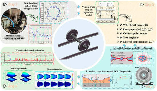
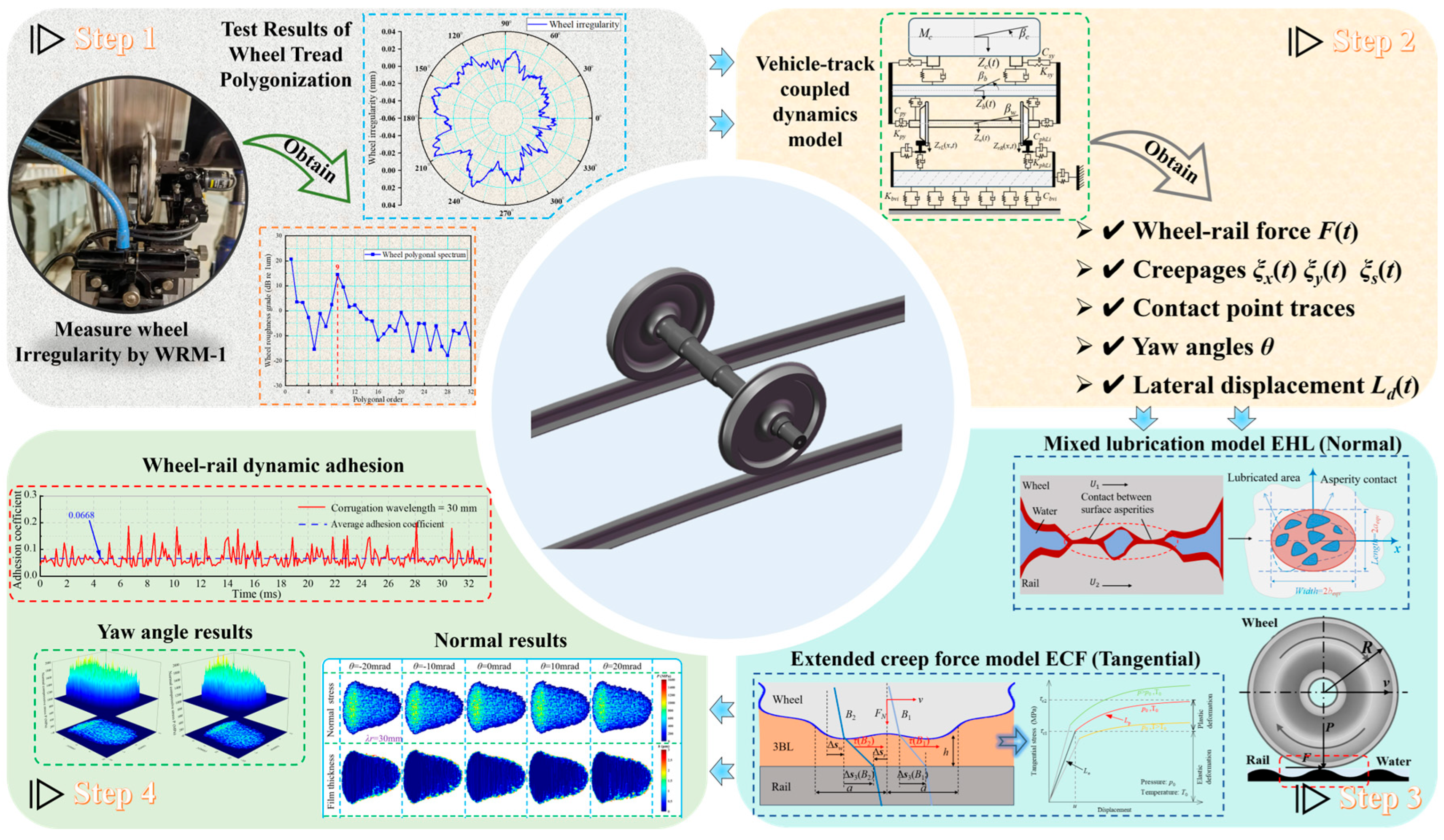
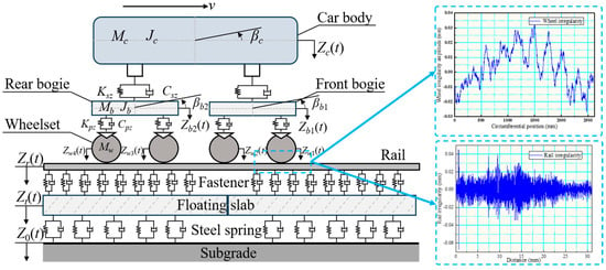
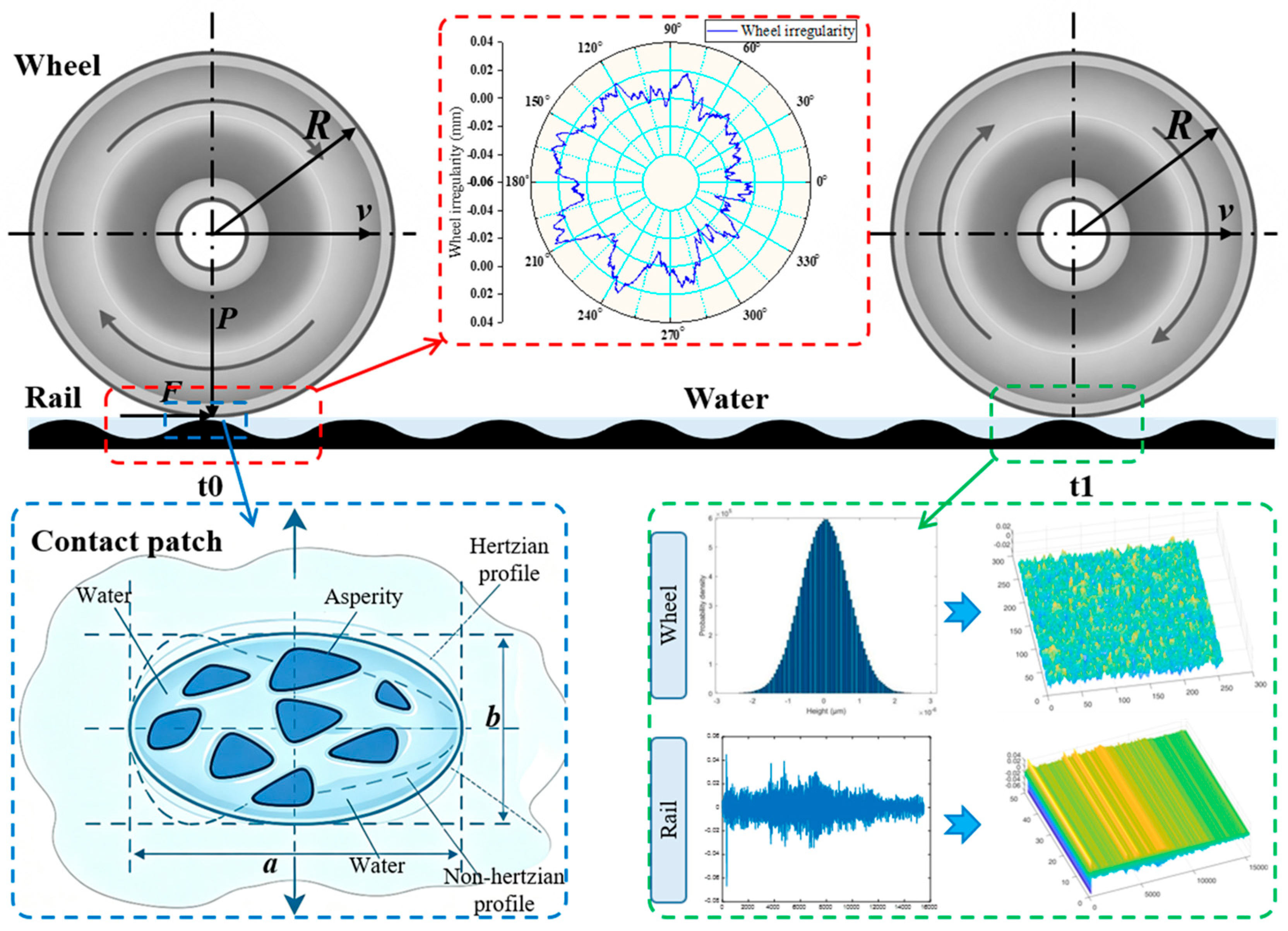
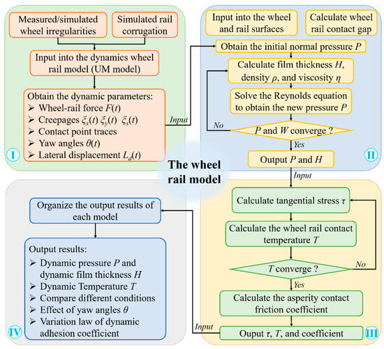
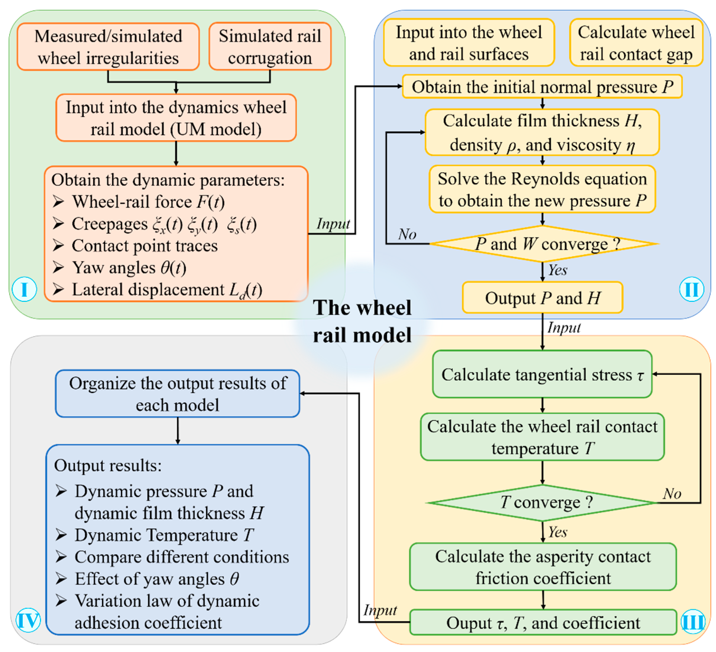
The numerical model proposed in this research integrates a vehicle–track coupled dynamics module and a transient wheel–rail rolling contact module that accounts for wheel polygonal wear and rail corrugation. As illustrated in Figure 1, experimentally measured wheel irregularity data are imported into the dynamics module, and sinusoidal rail corrugation is configured to simulate real-world vehicle operation and extract dynamic parameters. These dynamic parameters are subsequently fed into the wheel–rail rolling contact model, where the geometric contact relationship under conditions of wheel polygonal wear and rail corrugation is precisely considered. The EHL model is adopted to compute the normal pressure and water film thickness within the contact zone, followed by the ECF model to determine tangential forces and temperature. Finally, the dynamic rolling contact characteristics are output.
Figure 1.
Schematic diagram for investigating wheel–rail rolling contact behaviors considering wheel polygonization and rail corrugation.
2.1. Measured Wheel Polygonal Wear and Rail Corrugation
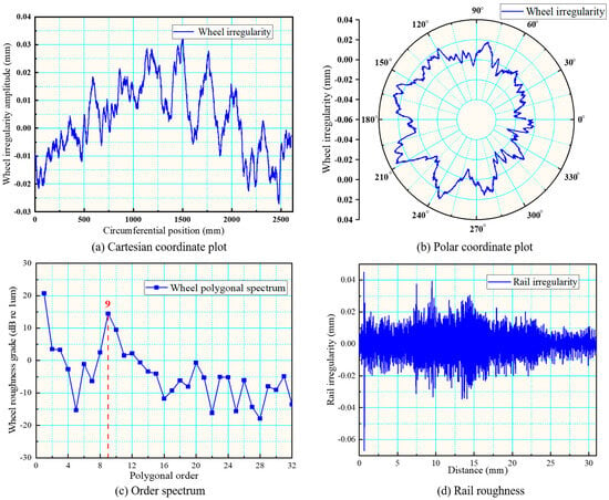
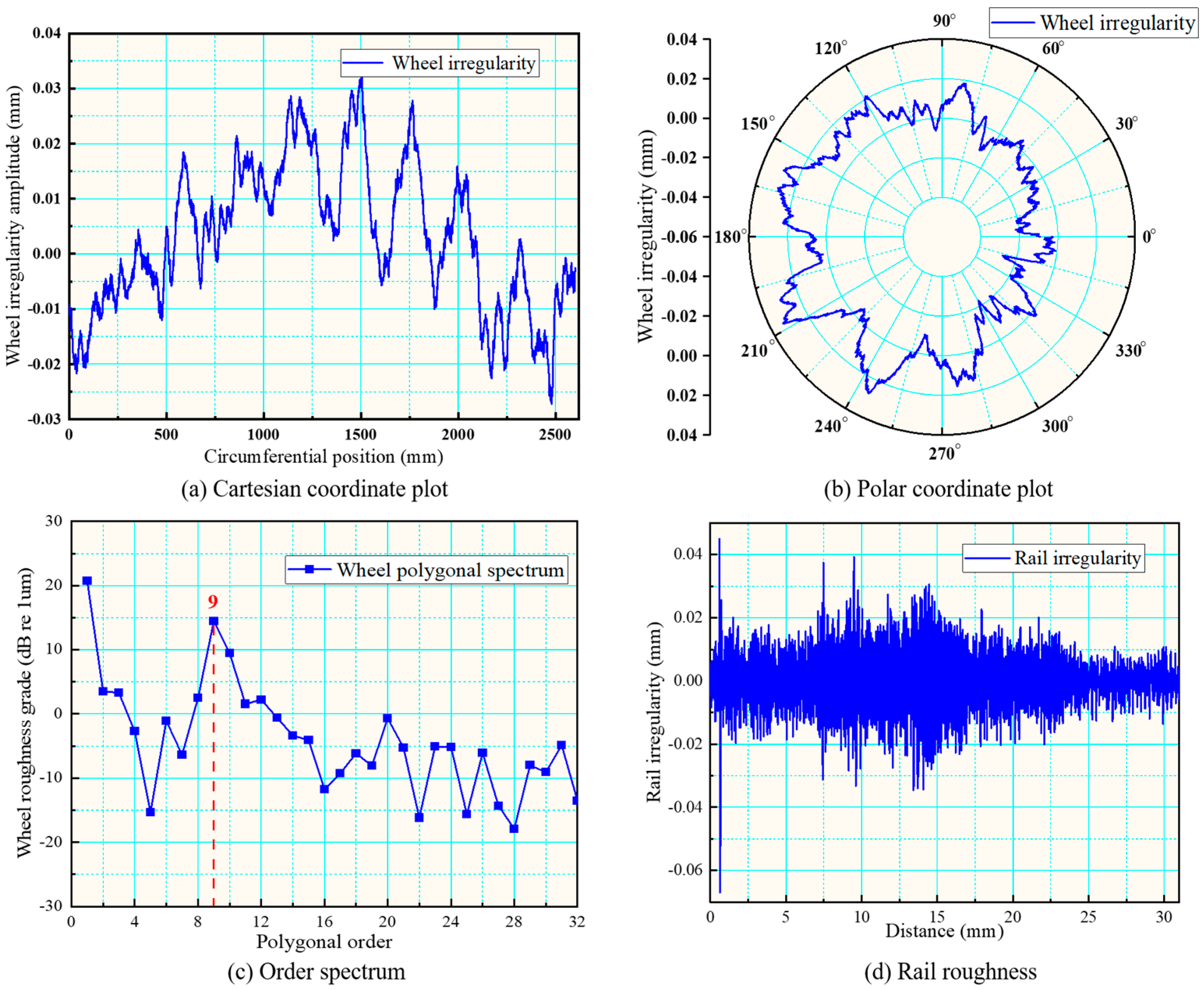
The circumferential irregularity of vehicle wheels is measured using the WRM-1 instrument. This device integrates displacement sensors for capturing radial deviations, magnetic sensors for marking measurement endpoints, and a rotary encoder for recording circumferential positions and angular phases. The system features a sampling interval of 1 mm and an accuracy of 0.1 μm, enabling high-resolution topographic data of the wheel tread to be obtained. Rail surface roughness is measured with a roughness tester. The measured results of wheel polygonal irregularity and rail roughness are shown in Figure 2. The results indicate that the wheel roughness level at the 9th order is more pronounced, and polygonal wear is dominated by the 9th order.
Figure 2.
Measured results of wheel polygonal irregularity and rail roughness.
To better simulate the influence of ideal wheel polygonalization on wheel–rail rolling contact behavior, this study employs a sinusoidal function to represent the circumferential polygonal wear of the wheel [26]:
where Aw denotes the amplitude of the Nth-order wheel polygonal wear, R0 denotes the nominal wheel radius, v represents the vehicle speed, and φw is the wheel phase angle. This expression describes the circumferential polygonal profile of the wheel and neglects the influence of lateral wheel wear.
Meanwhile, for the rail corrugation phenomenon, the same sinusoidal function is adopted in this study to generate it, and the expression is as follows:
where Ar is the amplitude of the rail corrugation, λr denotes the wavelength of the rail corrugation, x represents the running distance, and φr is the rail corrugation phase angle. On this basis, the measured rail roughness is added to characterize the actual rail.
2.2. Vehicle–Track Coupled Dynamics Model
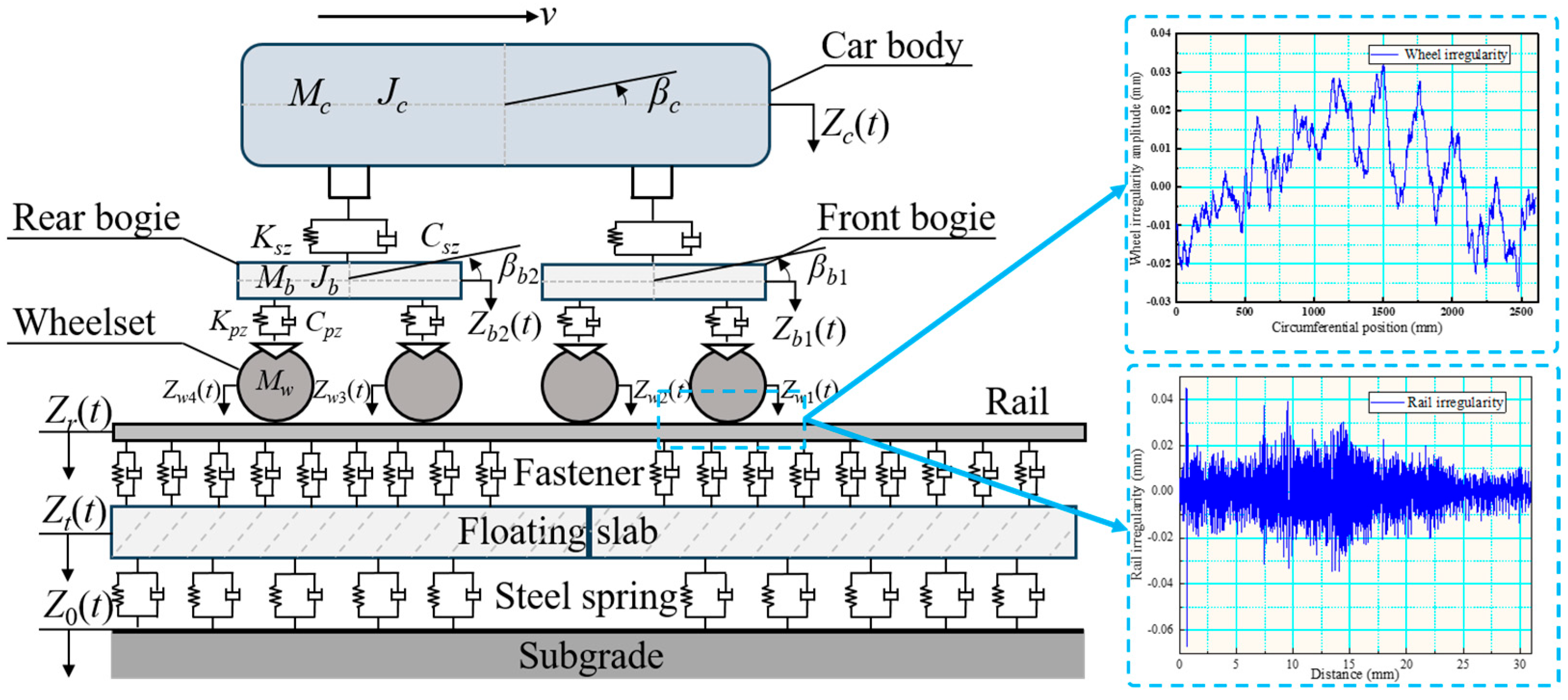
As shown in Figure 3, this study establishes a three-dimensional wheel–rail coupled dynamic model, which consists of a vehicle subsystem and a track subsystem. The vehicle subsystem contains one car body and two bogies, and each bogie is equipped with two wheelsets, which are connected to each other through primary and secondary suspensions. The track subsystem includes rails, fasteners, track slabs and cement asphalt mortar (CAM) layers. The fasteners and CAM layers are represented by spring damper elements. The rails are modeled as Timoshenko beams and coupled with track slabs via fastener systems. The track slabs are discretized using three-dimensional finite elements, and boundary conditions are applied according to the stiffness characteristics of the CAM layer [27]. The general vehicle–track coupled dynamics modeling framework and numerical solving algorithm can be found in reference [28]; this study adopts metro vehicle and metro track parameters referenced from publicly available literature on domestic A-type metro vehicles. On this basis, the wheel tread profile and rail corrugation parameters are incorporated into the model.
Figure 3.
Schematic diagram of the vehicle–track coupled dynamics model considering wheel polygonization and rail corrugation.
The equations of motion for the vehicle and track system are expressed as follows:
where the detailed descriptions of Equations (3) and (4) can be found in ref. [28].
In the vehicle–track dynamic model, the normal force is computed using nonlinear Hertzian contact theory. For tangential force calculation under water-lubricated conditions, a modified Fastsim algorithm [29] is employed to enhance simulation accuracy.
2.3. Dynamic Non-Hertzian Wheel–Rail Rolling Contact Model
The non-Hertzian dynamic wheel–rail rolling contact model proposed in this paper consists of two major components: a normal contact model based on the non-Hertzian EHL theory and a tangential contact model based on the non-Hertzian ECF theory. All input parameters required for these models are obtained from vehicle–track coupled dynamics simulations, taking into account the coupled effects of wheel polygonal wear, rail corrugation and water medium.
2.3.1. Calculation of Geometric Gap Considering Wheel Polygonization and Rail Corrugation
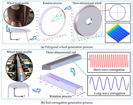
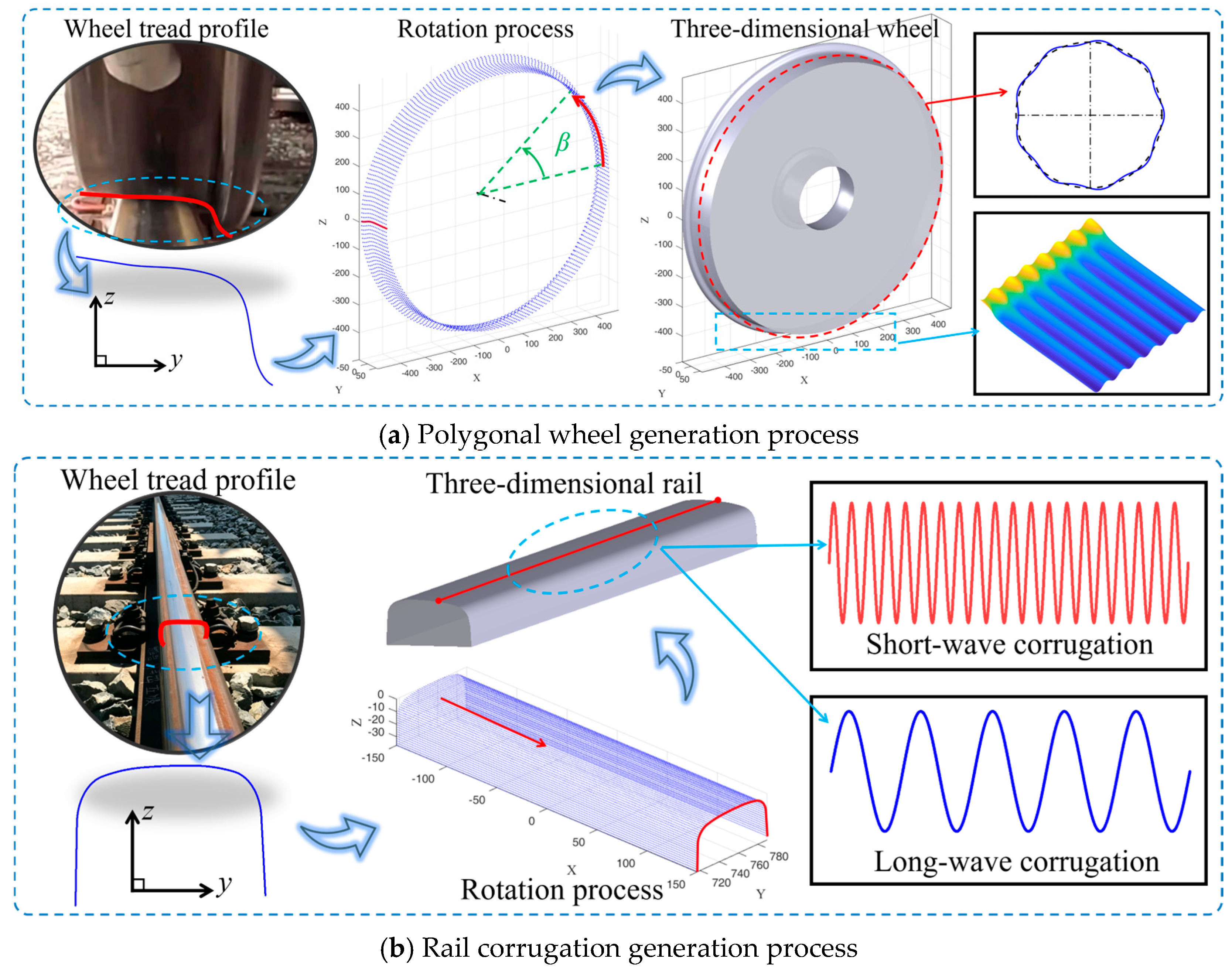
Wheel–rail rolling contact is a dynamic and stochastic process. The greatest difficulty in establishing a wheel–rail rolling contact model lies in accurately characterizing the dynamic effects of the coupling interaction between the wheel polygon surface topography and the rail. The simulation process for the polygonal wheel tread is illustrated in Figure 4a. On the basis of the original wheel tread profile, single-order circumferential polygon features and measured wheel tread profile data are superimposed, and corrections are performed respectively by rotating about the central axis. The coordinates of the wheel tread in the three-dimensional coordinate system can be calculated from the initial wheel tread profile coordinates (y, z) and the wheel rotation angle β. The specific calculation formulas are given as follows:
Figure 4.
Simulation process of three-dimensional wheel polygonal profile and rail corrugation.
In the three-dimensional wheel–rail contact model, the amplitude of wheel polygonal wear is much smaller than the wheel radius. Therefore, the local wheel circumferential height correction cwheel is performed within the range of the wheel–rail contact position xrail, and the size of xrail depends on the dimensions of the contact region. The specific calculation formula is as follows:
where r denotes the distance from the wheel center to the flange.
Similarly, the simulation process for the rail with corrugation is illustrated in Figure 4b. On the basis of the original rail cross-sectional profile, the rail is extended along the wheel running direction (x-direction), and rail surface roughness, together with sinusoidal waves of different wavelengths, is added to simulate the corrugated rail. The correction formula for the rail circumferential height crail is given as follows:
where drail represents the original rail profile.
crail = drail + Wr
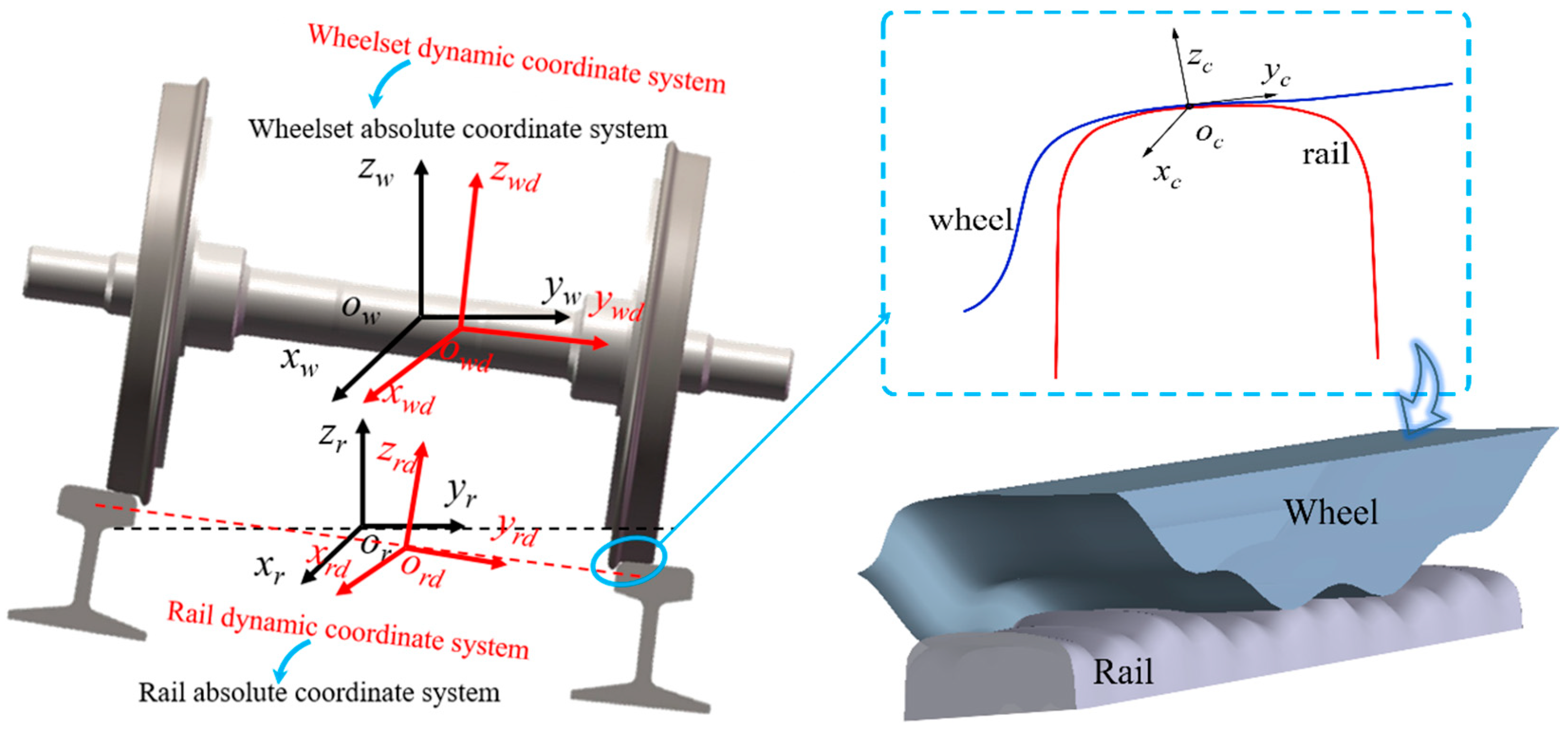
Subsequently, when wheel polygon topography and rail corrugation topography are incorporated into the wheel–rail contact analysis, the accurate capture of wheel–rail contact geometry becomes a critical challenge that directly determines the calculation accuracy of the model. To address this issue, coordinate transformation is adopted in this study to solve the three-dimensional contact gap. Using the trial-and-error method, contact points are initially identified within the contact zone, and the wheel–rail contact points are determined through precise scanning of the three-dimensional geometric gap. During the simulation calculation of the wheel–rail geometric gap, the definition of each coordinate system is illustrated in Figure 5. Ow and Or denote the absolute coordinate systems of the wheel and rail, respectively, which are fixed at the initial position of the wheelset mass center and translate with the track. Owd and Ord represent the dynamic coordinate systems of the wheel and rail, which are defined relative to the absolute coordinate systems. Oc denotes the local coordinate system of the contact patch.
Figure 5.
Coordinate system of wheel–rail contact geometric gap.
During rolling, the wheel and rail profiles modified for polygonization and rail corrugation are defined in the dynamic coordinate system. To guarantee calculation accuracy for the wheel–rail contact geometric gap, these profiles are transformed into the absolute coordinate system using the coordinate transformation given below:
where Mw and Mwd denote the coordinate matrices of the wheel and rail profiles in the absolute wheelset and dynamic coordinate systems, respectively. represents the position vector. θ denotes the yaw angle of the wheelset, and ψ represents the roll angle.
After coordinate transformation, the wheel and rail profiles are vertically aligned. Therefore, the vertical gap can be directly obtained from the coordinate difference. An iterative trial-and-error method is adopted to adjust the wheel roll angle and update the wheel–rail profiles, to finally determine the precise position of the contact point. Subsequently, the coordinates are transformed into the contact patch coordinate system via the formulas given below:
where Mc denotes the coordinate matrix of the wheel and rail profiles in the local contact patch coordinate system, represents the position vector from the wheelset absolute coordinate system to the local contact patch coordinate system, δ denotes the contact angle, and ζ represents the lead angle induced in the direction of travel due to polygonal wear or yaw motion of the wheel.
Accordingly, the wheel–rail contact geometric gap Gap is calculated using the following equation:
where and are the coordinate matrices of the wheel profile and the rail profile in the contact patch coordinate system, and are determined by wheel–rail geometry contact [30].
2.3.2. Wheel–Rail Normal Mixed Lubrication Model
Since water medium conditions are considered and roughness exists on the wheel and rail surfaces, the wheel–rail contact interface operates under mixed lubrication. The asperities and water film jointly bear the normal load, as illustrated in Figure 6. The wheel surface roughness is generated using a two-dimensional digital filtering method, while the rail surface roughness is reconstructed based on measured rail roughness data. For the criterion of mixed lubrication, asperity contact occurs when the water film thickness equals zero. Nevertheless, an extremely small film thickness threshold is generally adopted for judgment in numerical simulations. In this study, the threshold is set to ε = 10−9, consistent with the reference [31]. The Reynolds equation is expressed as follows:
where um denotes the velocity of the wheel in the x-direction; h represents the fluid film thickness between the two solid surfaces; ρ and η are the fluid density and viscosity, respectively; and p denotes the normal contact pressure.
Figure 6.
Wheel–rail normal interaction model.
The film thickness equation is modified as follows:
where h0 is the central film thickness; swheel and srail are the surface roughness of the wheel and the rail, respectively; E represents the composite elastic modulus; pl represents the fluid load-carrying pressure; and pc represents the asperity load-carrying pressure.
In this study, the classic Barus viscosity pressure equation is adopted, and its specific expression is as follows:
where η0 is environmental viscosity, and α is the Barus viscosity-pressure coefficient, with a value of 1 × 10⁻⁸.
η = η0exp(αp)
The expression for the fluid density equation is as follows:
where ρ0 is the ambient density.
The wheel–rail contact interface operates under mixed lubrication regime. The normal load is jointly borne by the fluid film and surface asperities, and the load balance equation satisfies the following expression:
2.3.3. Wheel–Rail Tangential Model
For the wheel–rail tangential model, considering wheel polygonal wear and rail corrugation under wet conditions, this study extends the extended creep force theoretical formula proposed by Meierhofer et al. [20] to non-Hertzian contact. The water film at the wheel–rail interface and surface roughness asperities are treated as an integrated third-body layer (3BL). The tangential model incorporates the Voce hardening law, thereby accounting for the elastoplastic behavior of materials. Since material properties are temperature-dependent, the thermal effect induced by wheel–rail contact is considered in the tangential model, and the required normal pressure is obtained by solving the EHL model. The expression for tangential stress is given as follows:
where τc1 and τc2 respectively denote the elastic and plastic shear stress limits, which are related to temperature and normal pressure [20]; Le and Lp represent the flexibility coefficient and plastic factor, which are also temperature-dependent and obtained experimentally [20]; and d is the total displacement of the third-body layer between wheel and rail, and its calculation formula is given as follows:
where t0 stands for the starting time of the contact process; ξx, ξy and ξs correspond to longitudinal, lateral and spin creepages; and vx and vy describe the longitudinal and lateral relative sliding velocities between paired contact points within the wheel–rail contact area.
Surface friction serves as the primary source of temperature rise within the wheel–rail contact region. The frictional power density q(t) of the third-body layer at the wheel–rail contact interface at an arbitrary time instant is computed using the equation below [20]:
where de is an elastic displacement, and the specific calculation process can be found in ref. [20].
The frictional power density of the wheel and rail can be calculated using the following equation:
where λw(r) is the thermal conductivity of the wheel or rail; κw(r) is the thermal diffusivity of the wheel or rail; vw is the circumferential velocity of the wheel; and v0 is the speed of the train.
Therefore, the temperature within the wheel–rail contact region at an arbitrary time instant can be written as:
On the basis of the above theory, the equation below is used to calculate the wheel–rail adhesion coefficient:
3. Numerical Procedure
The flowchart of the numerical model proposed in this study, which considers wheel polygonal profiles and rail corrugation, is shown in Figure 7. The overall model consists of two main parts: a vehicle–track coupled dynamics model and a wheel–rail rolling contact adhesion model. First, a wheel–rail multibody coupled dynamics model is established. The measured or simulated wheel tread irregularities and rail corrugation topography are used as the initial inputs of the model. By solving the model, dynamic parameters during wheel–rail rolling, such as the dynamic wheel–rail interaction force, creepages, and contact point trajectory, are obtained and then used as the input conditions for the wheel–rail adhesion model. The wheel–rail rolling contact adhesion model is composed of two parts: a normal elastohydrodynamic lubrication theoretical module and a tangential extended creep force theoretical module. Taking the wheel–rail surface topography information and the dynamic output parameters as initial values, the normal gap of the wheel–rail contact is calculated, the contact point position is determined, and the normal stress and fluid film distribution are obtained through an iterative solution. Subsequently, based on the normal stress and film thickness results, the tangential stress distribution of the wheel–rail contact and the wheel–rail contact temperature are calculated. After both have converged, the dynamic wheel–rail adhesion coefficient is further calculated, and the results are finally output.
Figure 7.
Calculation flowchart of the numerical model considering wheel polygonal wear and rail corrugation.
Compared with previous models, the major innovation of the present study lies in the coupling of wheel polygonal profiles and rail-corrugation topography within a precise solution framework that can accurately locate wheel–rail contact points. To ensure computational efficiency and accuracy, a second-order finite difference method is adopted to discretize the dimensionless equations, and the computational domain is discretized into a 257 × 257 equidistant mesh. The wheel surface roughness is generated using a two-dimensional digital filter with an exponential autocorrelation function combined with the FFT algorithm to produce a three-dimensional random surface topography, while the rail surface roughness is generated from measured data. In this study, the convergence criterion for pressure and load balance is set to 1 × 10⁻⁶, and the convergence criterion for the temperature field is set to 1 × 10⁻³.
4. Results and Discussion
4.1. Normal Contact Characteristics of Wheel–Rail Under Coupling of Single-Order Wheel Polygonization and Rail Corrugation
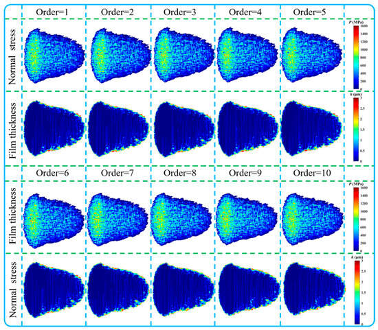
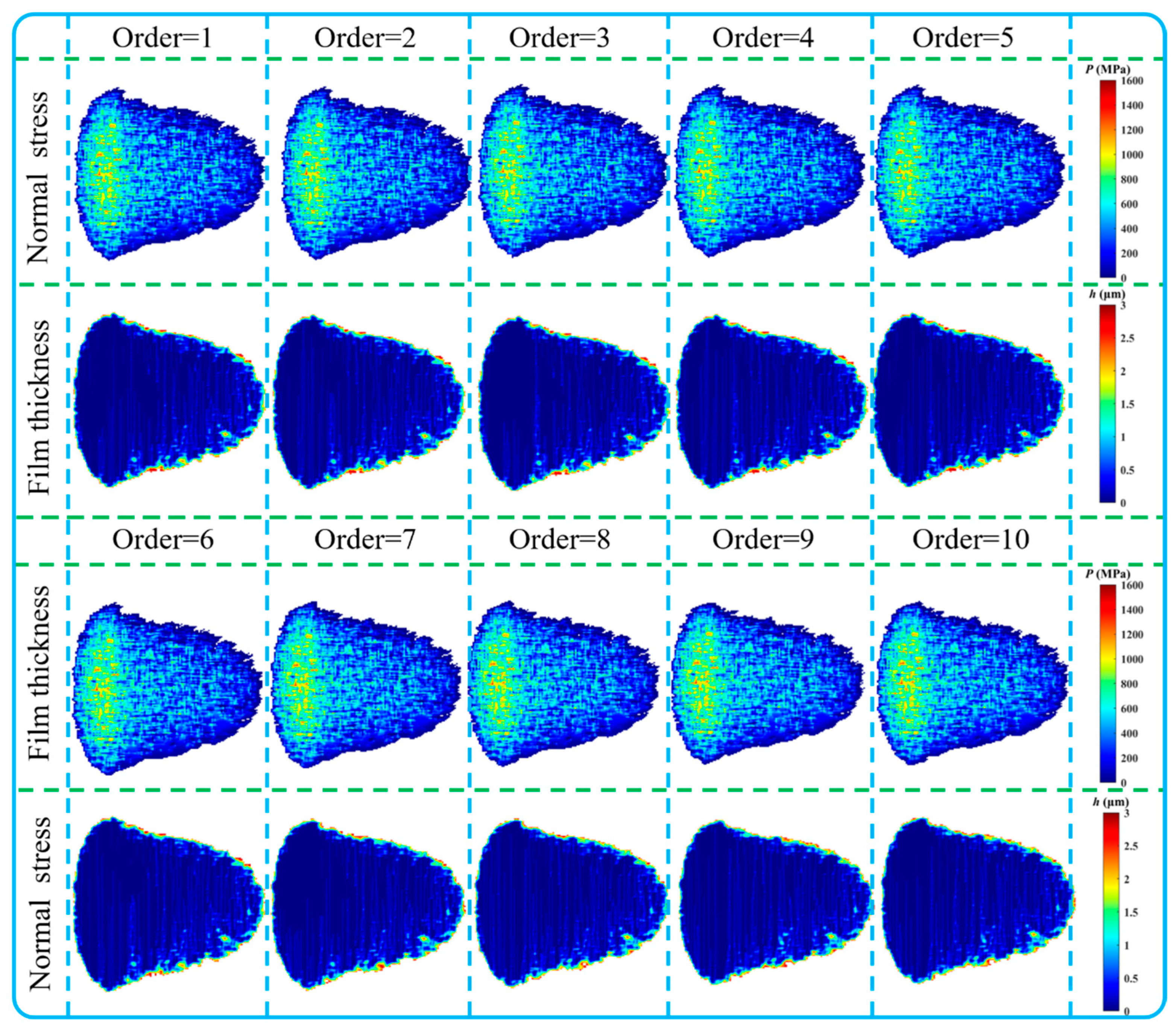
Metro-vehicle wheel polygonization is dominated by low-order components. In this section, multi-parameter simulations for ideal 1st- to 10th-order single-order polygonal wheels are carried out at an operating speed of 80 km/h. The aim is to investigate how coupled excitations from single-order wheel polygonization and rail corrugation affect normal-contact behavior at wet wheel–rail interfaces. In the preliminary simulation, the wheel polygonization amplitude was set to 0.06 mm, and the rail corrugation amplitude and wavelength were set to 0.05 mm and 30 mm, respectively. The resulting normal pressure and water film thickness distributions within the contact patch are presented in Figure 8. As shown in the contour plots of Figure 8, under the coupled action of low-amplitude polygonization and low-amplitude short-pitch corrugation, the wheel–rail contact patch generally maintains a typical non-Hertzian elliptical contact form over the 1st–10th-order range. The spatial distribution patterns of the normal stress in the contact patch are essentially identical for different polygon orders: the high-stress region is concentrated in the central part of the contact patch, and the stress gradually decays toward the periphery. The interface water film exhibits a mixed elastohydrodynamic lubrication distribution characterized by being thin in the central region and thick at the edges. Owing to the consideration of wheel and rail surface roughness, solid-surface asperities penetrate the water film to form local solid contact. Despite the variation in polygon order, no significant differences are observed in the contact patch geometry, the stress distribution pattern, or the overall magnitude of the water film thickness. This phenomenon indicates that macroscopic wheel geometry deformation caused by such low-amplitude polygonization and low-amplitude short-pitch corrugation has not yet induced local stress concentration or contact patch distortion.
Figure 8.
Distribution of compressive stress and water film thickness under coupled conditions of 1st- to 10th-order wheel polygonization and short-pitch rail corrugation: Aw = 0.06 mm, λr = 30 mm, Ar = 0.05 mm.
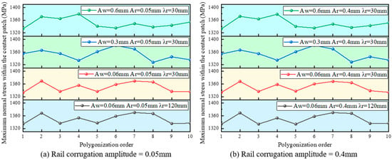
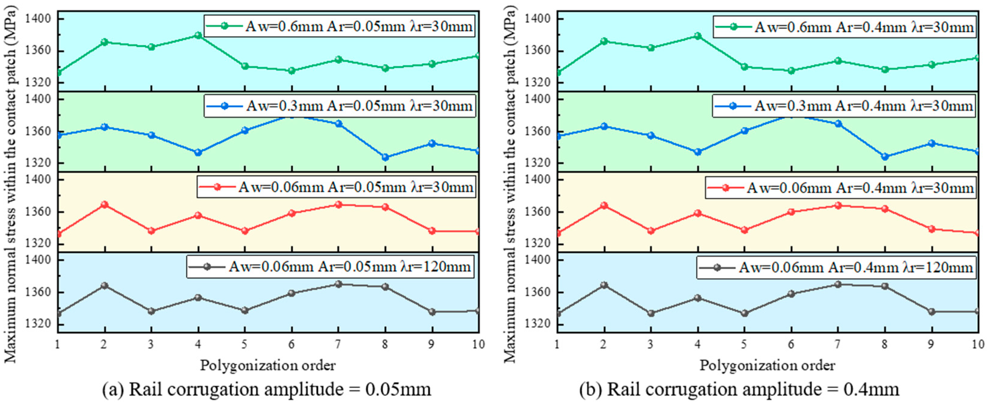
On this basis, wheel–rail contact characteristics were further computed under multiple operating conditions. The computational variables include the wheel polygonization amplitude Aw of 0.06 mm, 0.3 mm, and 0.6 mm, representing low, medium, and high degrees of polygonization wear, respectively; the rail corrugation amplitude Ar of 0.05 mm and 0.4 mm; and the rail corrugation wavelength λr of 30 mm, which represents short-pitch corrugation and 120 mm which represents long-pitch corrugation. The quantitative statistics in Figure 9 show that, across all simulated conditions, the maximum normal compressive stress in the contact patch is concentrated in the range of 1320–1380 MPa, which falls within the typical contact stress range of metro wheel–rail operation. Under the same rail corrugation condition, as the polygon amplitude increases from 0.06 mm to 0.6 mm, the vibration of the wheel–rail system amplifies, which in turn raises the peak dynamic normal force. Owing to the nonlinear relationship between the maximum compressive stress and the normal load, the maximum normal stress overall exhibits only a slight increase. By comparing Figure 9a with Figure 9b, it is found that increasing the rail corrugation amplitude does not cause an obvious deviation in the maximum normal stress under the same polygon condition; likewise, when comparing short-pitch and long-pitch corrugation results, the change in wavelength also induces only a slight stress fluctuation. The underlying mechanism is as follows: the characteristic dimension of the wheel–rail contact patch is on the order of several millimeters, which is much larger than the surface micro-roughness but far smaller than the rail corrugation wavelengths of 30 mm and 120 mm. Rail corrugation is a slowly varying macroscopic geometric undulation whose primary effect is to excite dynamic loads in the vehicle–track system, while it barely changes the local equivalent curvature radius of the contact region. Therefore, under the conditions considered, changes in corrugation amplitude and wavelength are mainly reflected in the oscillation of the system-level dynamic force, whereas their regulating effect on the peak stress inside the contact patch is limited.
Figure 9.
Maximum normal compressive stress under coupled conditions of different single-order polygonal wheels and rail corrugation.
Within the low-order range of 1st–10th order, the maximum normal stress exhibits only slight oscillation with increasing polygon order, without any monotonic increasing or decreasing trend. Since the circumferential geometric wavelength of even the 10th-order polygonal wheel remains much larger than the wheel–rail contact patch dimension, it can be inferred that changing the polygon order essentially alters the dominant excitation frequency rather than significantly modifying the local geometric curvature of the contact region. In addition, the mixed elastohydrodynamic lubrication condition in the wet state further weakens the stress fluctuation. The hydrodynamic effect of the water film shares a portion of the normal load: when the wheel–rail system undergoes dynamic unloading, the load-bearing proportion of the water film increases; conversely, when the load increases, the proportion of solid contact carried by asperities rises. This load redistribution between the fluid film and the asperities further buffers the variation of the peak stress in the contact patch caused by external excitation.
4.2. The Influence of Yaw Angle on the Wheel–Rail Contact Behaviors
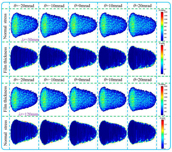
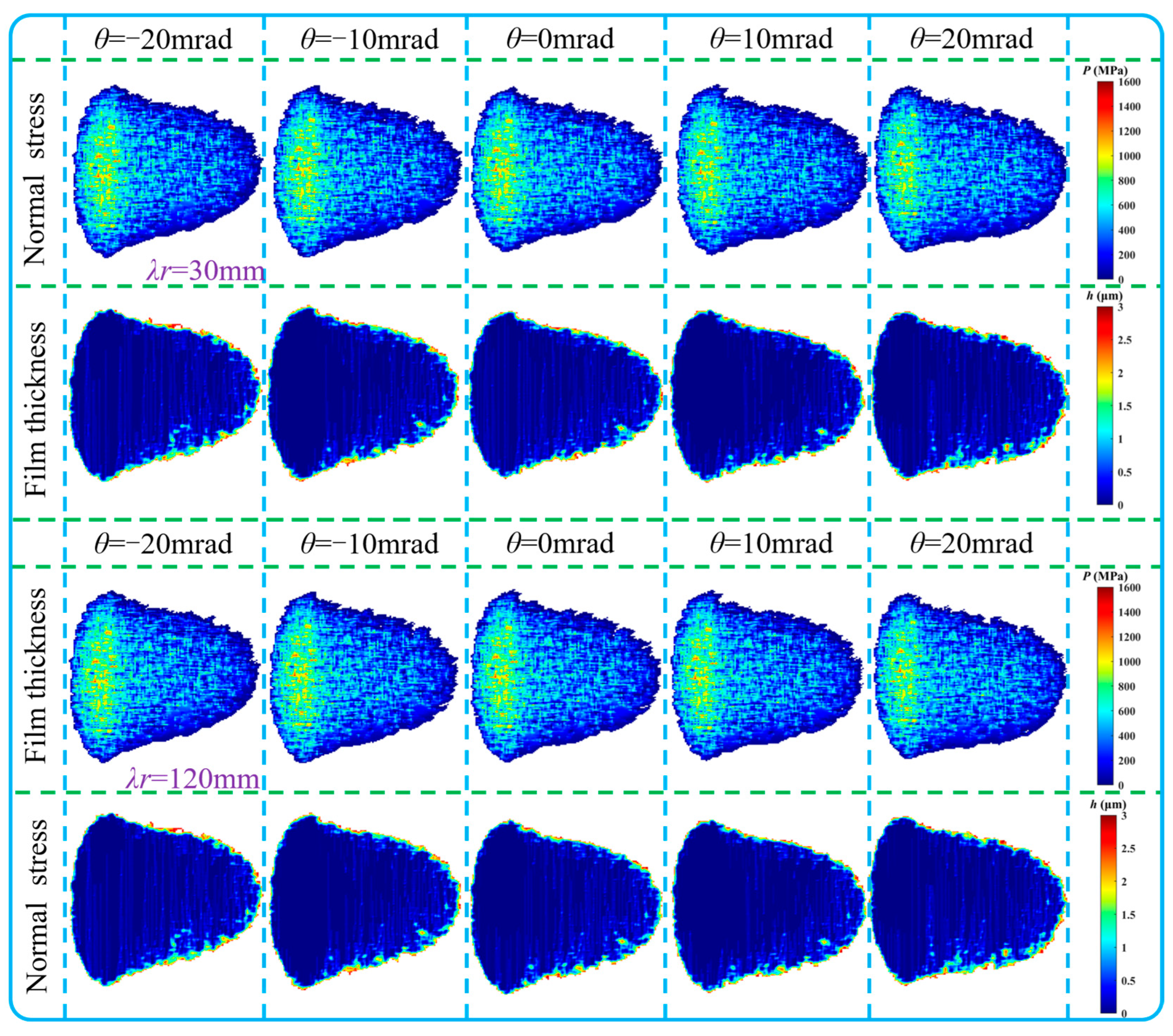
Yaw motion is an inherent dynamic behavior of wheelsets during metro vehicle negotiation of curves and track irregularities. The yaw angle alters the relative geometric posture between wheel and rail, redistributes the contact position and contact stress within the wheel–rail contact patch, and further interferes with the water film distribution under wet mixed-lubrication conditions. Combined with wheel polygonization and rail corrugation excitations, the yaw angle jointly modulates the normal contact state of wheel–rail interface. Figure 10 illustrates the contour distributions of normal contact stress and water film thickness within the contact patch under rail corrugation wavelengths of 30 mm and 120 mm, with the yaw angle ranging from −20 mrad to 20 mrad, and a 9th-order polygonal wheel and rail corrugation amplitude of 0.4 mm. It can be observed that neither short-pitch nor long-pitch rail corrugation produces obvious differences in contact patch morphology, peak normal stress magnitude and water film spatial distribution. The high-stress zone is always concentrated in the central region of the contact patch, and the water film maintains the typical mixed elastohydrodynamic lubrication feature of a thin center and thick edges. The underlying physical mechanism lies in the fact that the contact patch characteristic size of metro wheel–rail interactions is only several millimeters. Both 30 mm corrugation and 120 mm corrugation are macroscopic long-wave geometric undulations compared with the local contact scale. Rail corrugation mainly excites global vehicle–track system dynamic load oscillation rather than modifying the local equivalent curvature of the wheel–rail contact area. When the yaw angle is limited to the range of (−20 mrad~20 mrad), the contact point lateral migration amplitude induced by yaw rotation is still confined within the macroscopic geometric undulation period of rail corrugation. Therefore, the local contact geometry perceived by the contact patch barely distinguishes between short-pitch and long-pitch corrugation, leading to insignificant discrepancies in normal stress and water film distribution between the two wavelength conditions.
Figure 10.
Effect of yaw angle on wheel–rail normal contact under different rail corrugation wavelengths.
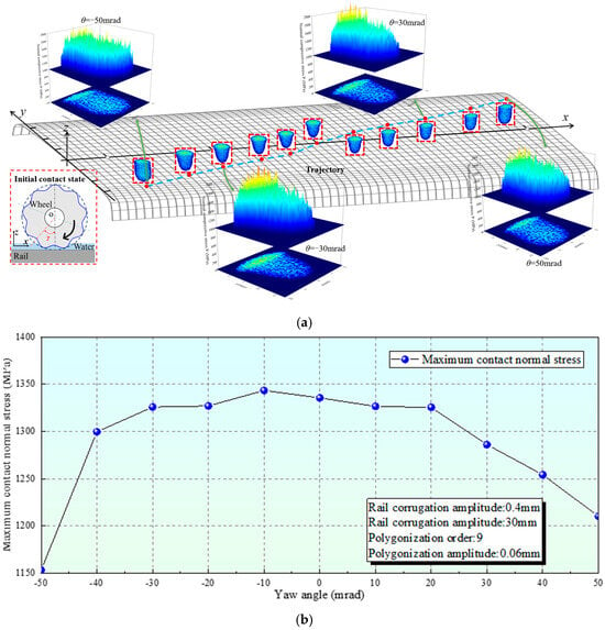
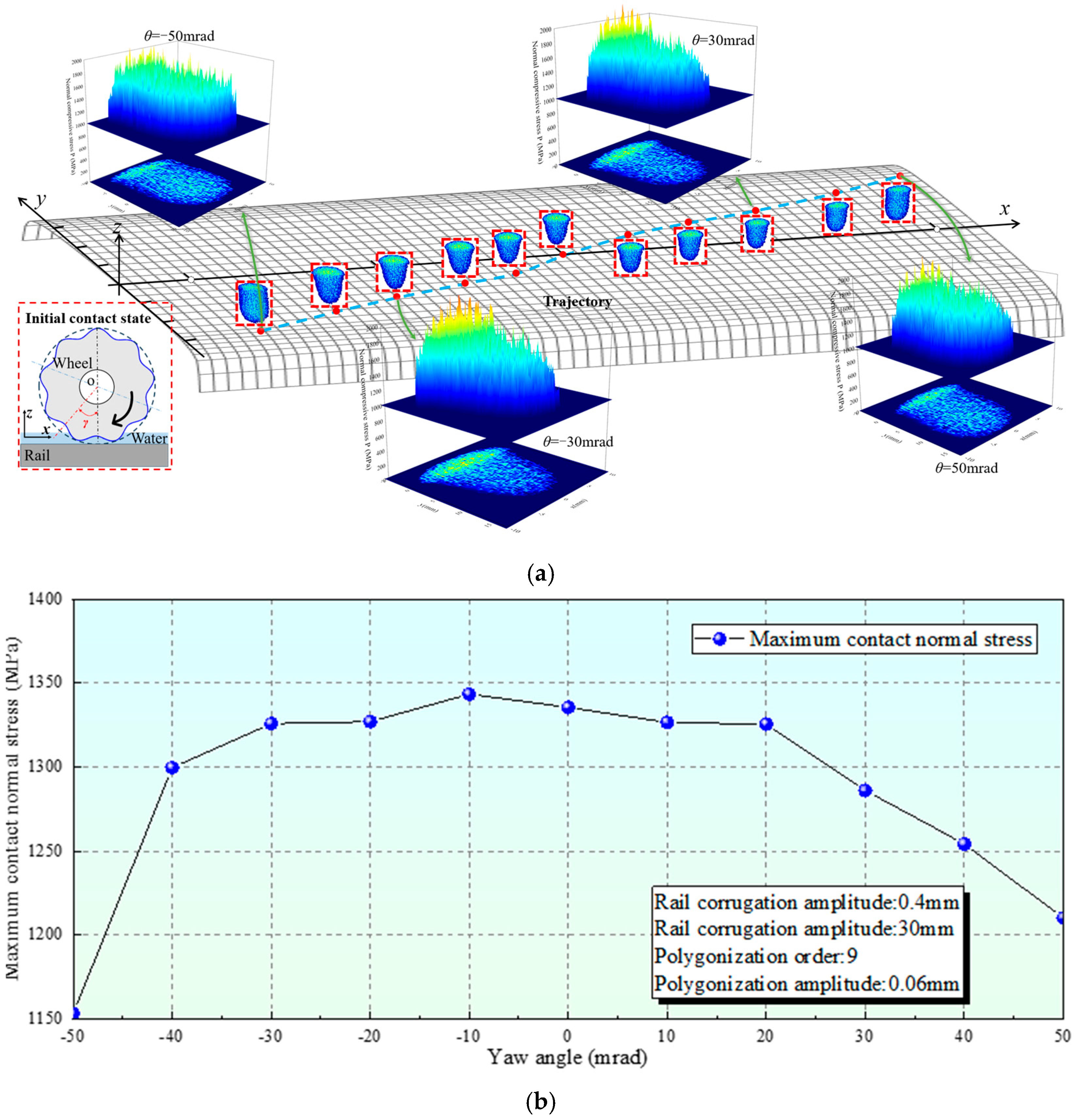
To further reveal the comprehensive influence of wheelset yaw posture on wheel–rail contact characteristics under the coupling effect of 9th-order wheel polygonization and 0.4 mm amplitude short-pitch rail corrugation, the yaw angle range is expanded to −50 mrad~50 mrad. Figure 11a demonstrates the contact point trajectory and three-dimensional normal pressure distribution under typical yaw angles. As the absolute value of the yaw angle increases, the wheelset produces an obvious lateral deflection relative to the rail, which drives continuous lateral migration of wheel–rail contact points along the rail top surface. A large yaw angle significantly distorts the original elliptical contact patch profile; the contact region gradually deviates from the center of the wheel tread, and local stress concentration appears at the edge of the contact patch.
Figure 11.
Effect of yaw angle under coupling of polygonal wheels and rail corrugation. (a) Wheel–rail contact point trajectory and three-dimensional normal pressure distribution under different yaw angles; (b) Variation of maximum contact compressive stress with yaw angle.
The quantitative curve of maximum contact compressive stress varying with yaw angle is shown in Figure 11b. It can be seen that the maximum normal contact compressive stress presents an obvious non-monotonic variation trend as the yaw angle changes from −50 mrad to 50 mrad. The variation characteristics of the contact patch are jointly governed by contact-point migration, contact-patch area evolution and the mixed-lubrication load-bearing mechanism. For the yaw angle within this range, the induced lateral displacement of the wheelset moves the contact point towards the wheel-tread shoulder region. The local wheel–rail equivalent contact curvature increases, and the effective contact-patch area changes. When the yaw angle becomes excessively large, the contact point migrates further towards the wheel flange root region. The geometric matching relationship between the wheel tread and the rail head deteriorates severely; local contact loss occurs at the contact interface, which may lead to local transient separation. Under the wet mixed elastohydrodynamic lubrication state, the water film can intrude into the local separation zone and bear part of the normal load. The proportion of solid asperity contact decreases, thereby buffering the peak solid contact pressure. Consequently, under large-amplitude yaw angles, the maximum compressive stress of the contact patch exhibits a significant descending trend.
Moreover, wheel polygonization introduces circumferential periodic geometric excitation, which is superimposed on the contact-geometry variation induced by yaw angle. Even though the global vertical dynamic wheel–rail force does not change drastically, the local contact patch stress distribution will still be modulated by the combined effect of yaw angle-induced contact point offset and wheel polygonal circumferential geometry fluctuation. It should also be noted that the asymmetric distribution of maximum stress between negative and positive yaw angles originates from the superposition of the 9th-order wheel polygonal geometric phase and the direction of wheelset yaw deflection.
4.3. Tangential Characteristics of Wheel–Rail Contact and Temperature Effects
Based on the normal contact analysis results in Section 4.2, the wheelset yaw angle markedly alters the wheel–rail contact point position, contact patch morphology and normal stress distribution. In this section, the ECF tangential contact model is employed, in which the water film and wheel–rail surface asperities are jointly represented as a 3BL; the Voce hardening constitutive law is introduced to account for the elastoplastic deformation of the third-body layer; and the weakening effect of contact flash temperature on shear strength is coupled. This allows for further clarification of the evolution laws of wheel–rail tangential stress, contact flash temperature and friction coefficient under water-wetted conditions subjected to the coupled action of yaw angle, wheel polygonization and rail corrugation. The calculation results are shown in Figure 12.
Figure 12.
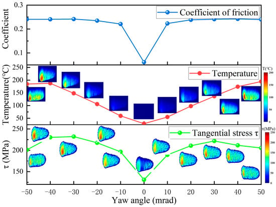
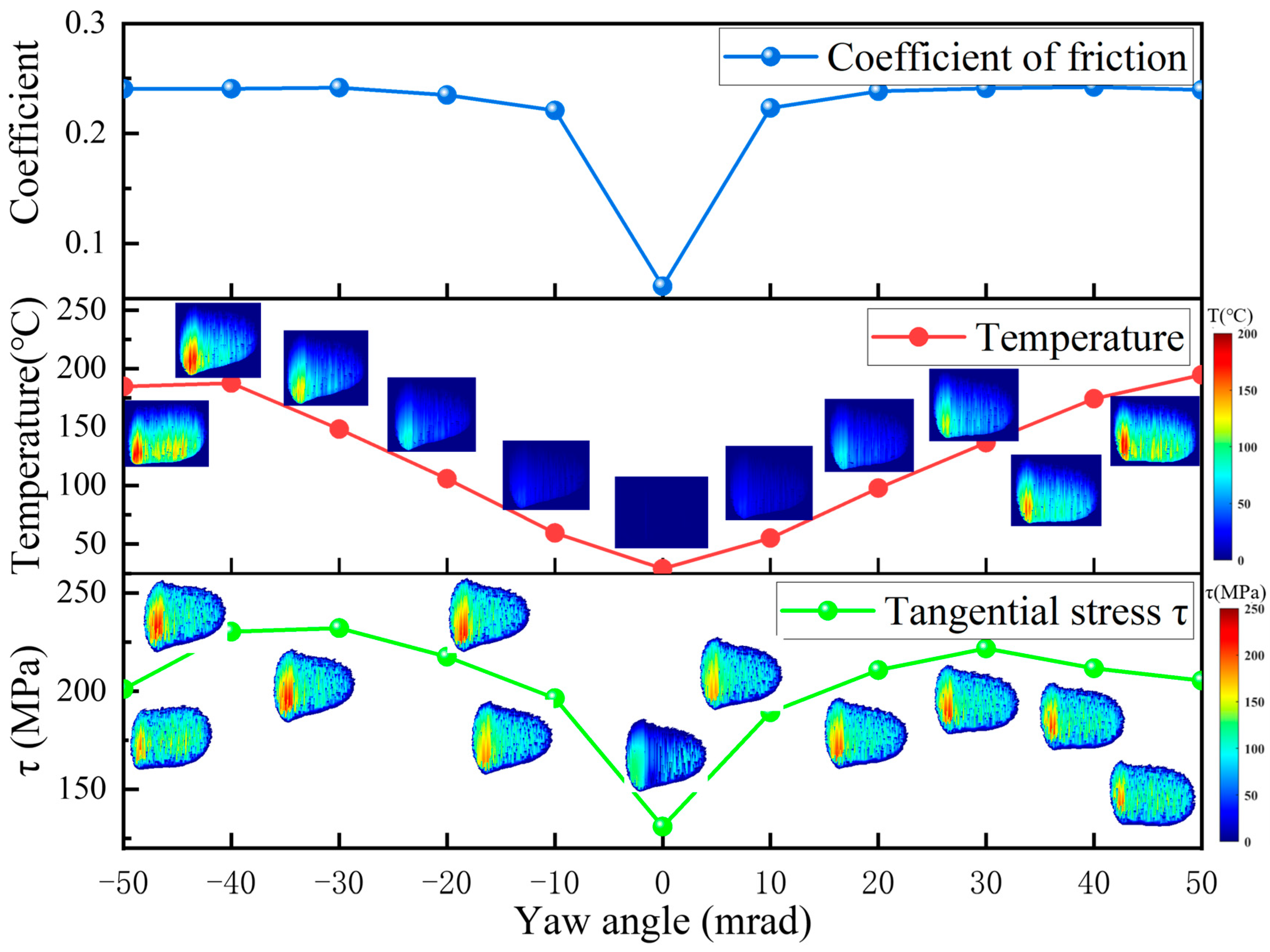
Tangential results considering wheel polygonization and rail corrugation.
Figure 12 presents the variation curves of contact flash temperature, tangential stress and friction coefficient with yaw angle within the wheelset yaw angle range of −50 mrad to 50 mrad, under the coupled condition of 9th-order wheel polygonization with an amplitude of 0.06 mm and short-pitch rail corrugation with an amplitude of 0.4 mm. Contour distributions of the temperature field and tangential stress field are also embedded. The results show that the evolution of the friction coefficient, contact flash temperature and tangential stress with yaw angle exhibits highly consistent non-monotonic variation characteristics. At a yaw angle of 0 mrad, the maximum tangential stress is 131 MPa; meanwhile, the friction coefficient exhibits a pronounced sharp valley of only 0.06, which is close to the mean wheel–rail adhesion coefficient under wet conditions, and the contact flash temperature simultaneously drops to its lowest level. As the absolute value of the yaw angle increases, the tangential stress, friction coefficient and flash temperature rise synchronously again. However, the curves under positive and negative yaw angles are not completely symmetric. This asymmetry originates from the superposition effect of the circumferential geometric phase of the 9th-order wheel polygonization and the direction of the wheelset yaw angle.
From the contour distributions, it can be seen that the tangential stress within the contact patch exhibits a clearly non-uniform spatial distribution under all conditions, with high tangential stress values concentrated in the trailing edge region of the contact patch, which is consistent with the typical characteristics of rolling contact. During the wheel–rail rolling process, the leading edge of the contact patch is dominated by the adhesion zone with small shear deformation, whereas the slip proportion at the trailing edge increases, the shear deformation of the third-body layer becomes fully developed, and the tangential stress concentrates. Under water medium mixed lubrication conditions, the water film thickness at the edge of the contact patch is greater and the probability of asperity contact is low; consequently, the tangential stress level at the edge of the contact patch is significantly lower than that in the central and trailing edge regions. As the yaw angle increases, the contact patch undergoes lateral deformation, and the high tangential stress region migrates accordingly towards the lateral edge of the contact patch. Under large yaw angles, local edge stress concentration even occurs. This position has a high frictional power density, and the flash temperature rises correspondingly, which will aggravate the risk of local tread scuffing and spalling-type damage.
4.4. Dynamic Wheel–Rail Adhesion Characteristics
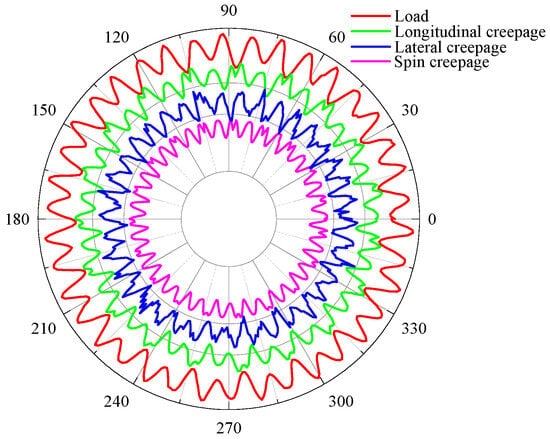
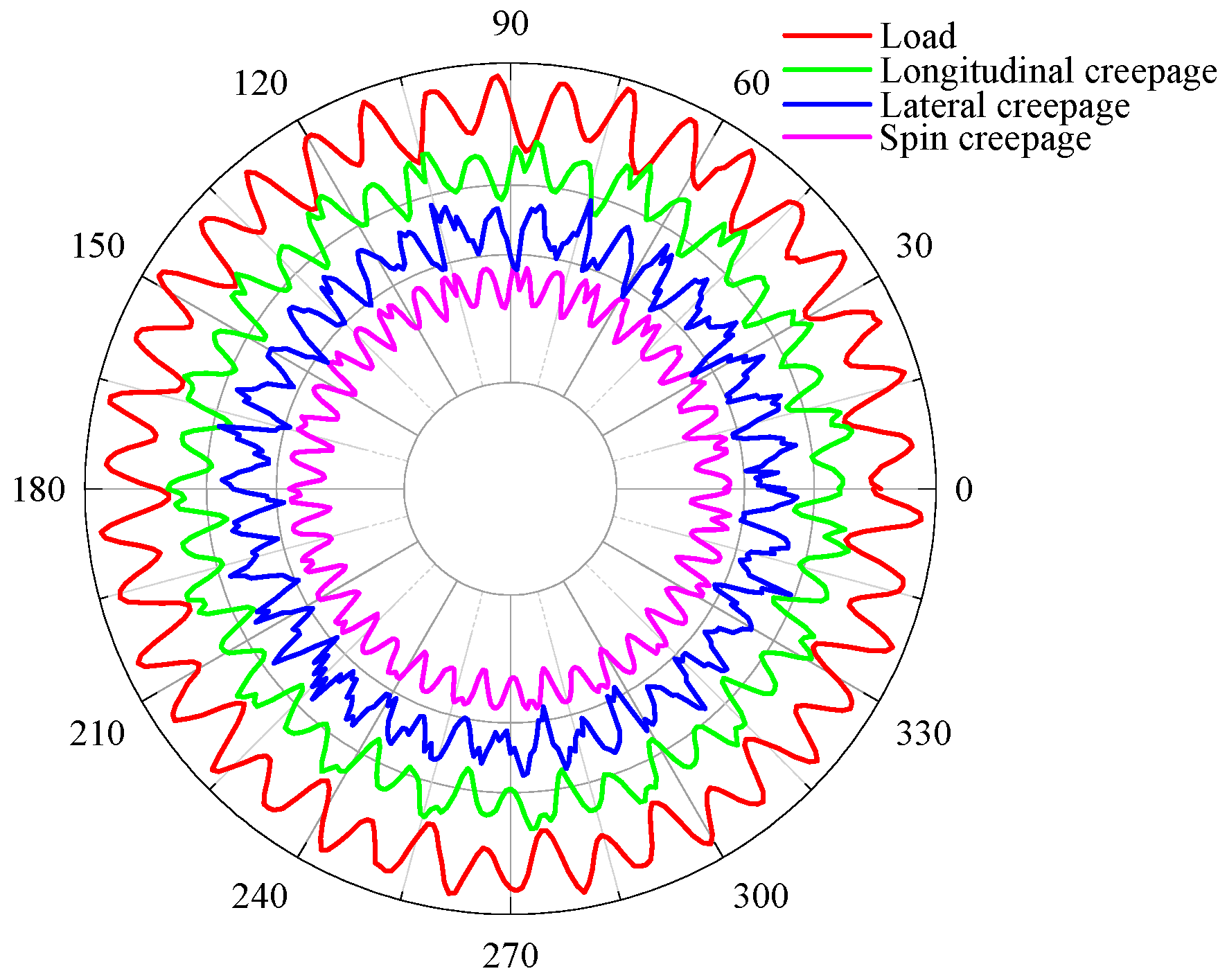
The aforementioned studies are based on idealized single-order polygonal wheels and ideal rail corrugation. However, during actual vehicle operation, wheel polygonal irregularities contain multiple harmonic orders. In this section, a measured metro polygonal wheel tread profile is introduced to thoroughly investigate the dynamic rolling contact characteristics and adhesion coefficient variations of an actual polygonal wheel passing through a corrugated rail section. A short-pitch corrugation of 30 mm is selected. The corrugation amplitude is 0.4 mm, and the speed is 80 km/h. Figure 13 presents the dynamic parameters output by the vehicle–track coupled dynamics model under this condition. The results indicate that during the rolling process, the excitation from two types of periodic defects, polygonization and corrugation, continuously alters the geometric clearance between the wheel and rail, triggering severe fluctuations in the wheel–rail normal force, creepage, and contact point trajectory, which causes the wheel–rail dynamic parameters to exhibit pronounced oscillatory characteristics.
Figure 13.
Dynamic parameters for the EHL and ECF model inputs at 80 km/h.
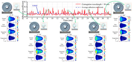
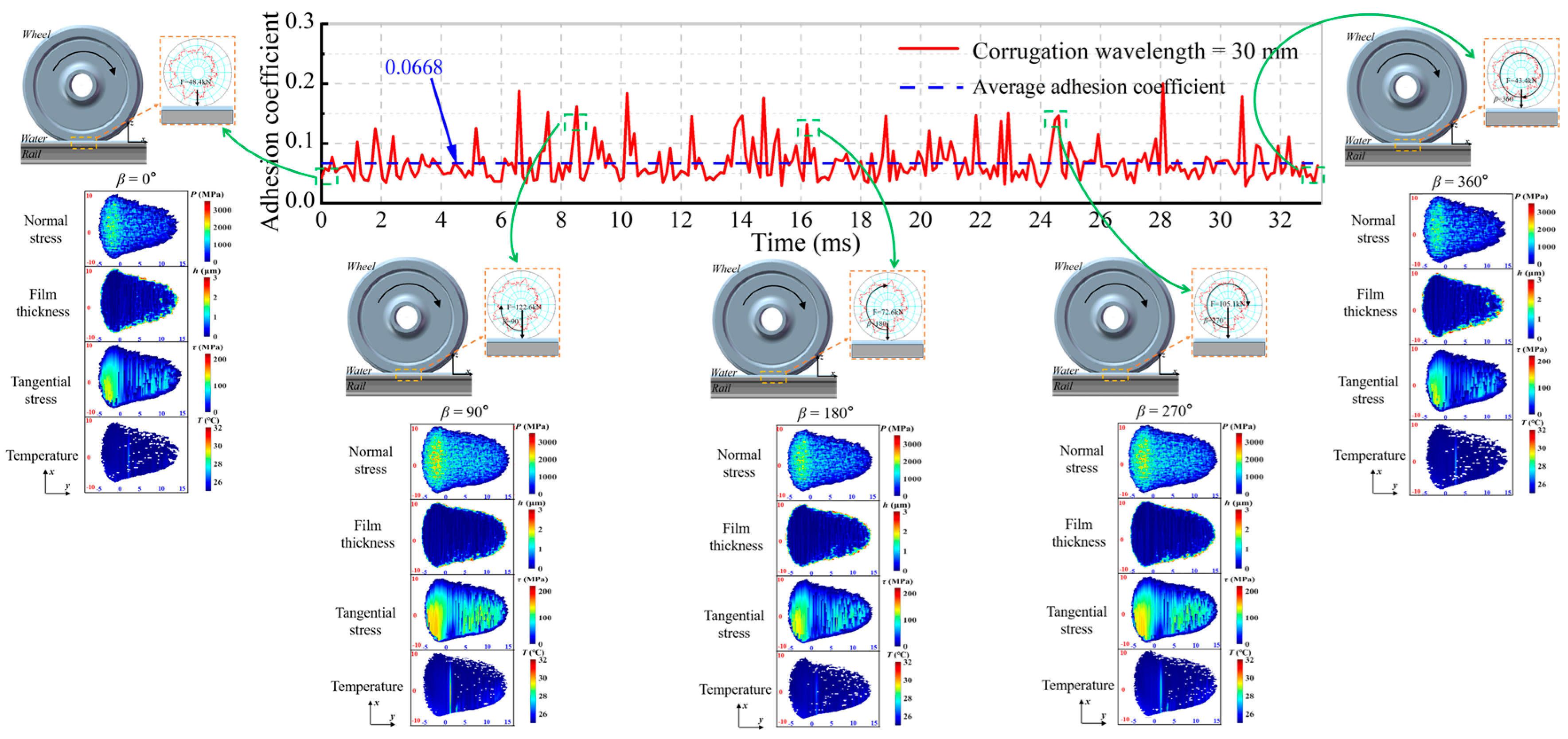
Figure 14 presents the friction coefficient of the polygonal wheel rolling along the corrugated rail section over one complete wheel rotation cycle and extracts the distributions of normal stress, water film thickness, tangential stress, and temperature field within the contact patch at five typical rotational positions. The results indicate that, compared with a single excitation, the superposition of measured wheel polygonization and short-pitch corrugation produces an excitation amplification effect, further enlarging the fluctuation amplitude of the wheel–rail dynamic force. Drastic variations in contact load directly alter the proportions of asperity contact and water film load-bearing within the contact zone under mixed lubrication conditions. When the wheel–rail force decreases, the water medium is more easily entrained into the contact interface to form a thicker water film, and the instantaneous adhesion coefficient decreases significantly. At load peak positions, however, the interfacial water is squeezed out, the proportion of direct asperity contact increases, and the instantaneous adhesion coefficient is briefly restored. The alternating cyclic characteristics of the adhesion coefficient are dominated by the dynamic contact state rather than being determined solely by the static surface topography.
Figure 14.
Wheel–rail dynamic adhesion coefficient under the coupled condition of measured wheel polygonization and rail corrugation.
At the same operating speed, compared with long-pitch corrugation, the selection of 30 mm short-pitch corrugation evidently generates higher frequency excitation, which, when coupled with actual wheel polygonization, readily causes longitudinal creepage saturation and induces strong wheel–rail longitudinal stick–slip vibration, resulting in a significantly larger oscillation amplitude of the adhesion coefficient. Under wet conditions, the average adhesion coefficient for the coupled condition of short-pitch corrugation and wheel polygonization is approximately 0.06, which falls within the low adhesion range and leads to frequent instantaneous low adhesion events, making wheelset idling and sliding risks more likely to occur.
When the dynamic unloading effect is relatively strong, local instantaneous separation of the wheel and rail occurs at certain moments. Once local separation occurs, the third-body water medium completely fills the contact gap, and the wheel–rail tangential load-bearing capacity drops sharply. The deterministic mixed elastohydrodynamic model established in this paper updates the three-dimensional contact gap in real time through coordinate transformation, enabling it to capture such non-Hertzian transient contact characteristics, whereas traditional adhesion calculation models based on Hertzian contact cannot reproduce this phenomenon. Meanwhile, the frictional flash temperature obtained from the ECF module solution acts back on the shear strength parameters of the third-body layer, altering the tangential stress distribution and further regulating the adhesion behavior. Under wet conditions, the dynamic load, water film pressure, contact flash temperature, and material elastoplastic properties are mutually coupled, collectively determining the evolution law of the wheel–rail dynamic adhesion coefficient.
From an engineering perspective, even if the average adhesion coefficient does not deteriorate significantly, the coexistence of multi-order wheel polygonization and short-pitch rail corrugation still frequently triggers instantaneous low adhesion events. Such intermittently occurring low adhesion moments are important hidden hazards for the safe operation of metro traction and braking. Therefore, relying solely on static or time-averaged adhesion coefficients is insufficient to comprehensively assess line risk. In metro low-adhesion safety evaluation, both the oscillation amplitude and the occurrence frequency of the adhesion coefficient should also be taken into account.
It should be noted that the wheel polygonization and rail corrugation excitation in this model are set symmetrically. In practical metro operations, asymmetric damage often occurs: only one wheel of the leading wheelset suffers polygon wear, and rail corrugation is mainly distributed on the low rail of curved tracks. This asymmetric damage characteristic is not considered in the current simulation, which is a limitation of this study. Further research will be conducted to reveal the dynamic behaviors under asymmetric wheel–rail defects.
5. Conclusions
This study develops a numerical model integrating vehicle–track coupled dynamics, non-Hertzian mixed EHL, and ECF theory, considering coupled wheel polygonization and rail corrugation, wet interface conditions, and flash temperature. The main conclusions are as follows:
- (1)
- Under low-amplitude single-order wheel polygonization and rail corrugation, the contact patch is much smaller than the corrugation wavelength and the circumferential wavelength of low-order polygonal wheels, so local peak normal contact stress and contact patch morphology change little.
- (2)
- The wheelset yaw angle significantly alters wheel–rail contact geometry and contact patch shape, causing non-monotonic variations in maximum normal compressive stress, tangential stress, flash temperature, and adhesion coefficient. High tangential stress concentrates at the trailing edge of the contact patch. Large yaw angles induce edge stress concentration, raise local flash temperature, and increase the risk of wheel tread scuffing and spalling.
- (3)
- The superposition of measured polygonal wear and short-pitch rail corrugation amplifies wheel–rail dynamic excitation, causing severe oscillation of normal force and creepage. In wet conditions, liquid easily enters the contact interface, producing instantaneous low-adhesion states.
- (4)
- Under wet conditions, wheel–rail dynamic adhesion is jointly determined by dynamic contact load, water film pressure, flash temperature, and the elastoplastic properties of the interfacial third-body layer.
Author Contributions
Conceptualization, P.P., P.S. and B.W.; methodology, P.P.; software, P.S.; validation, P.S., B.W. and P.P.; formal analysis, B.W.; investigation, P.S.; resources, B.W.; data curation, P.S.; writing—original draft preparation, P.P.; writing—review and editing, B.W.; visualization, P.S.; supervision, B.W.; project administration, P.S. and P.P.; funding acquisition, B.W. and P.P. All authors have read and agreed to the published version of the manuscript.
Funding
The present work has been supported by the National Nature Science Foundation of China (Nos. 52372391, U21A20167) and the National Key Research and Development Program of China (2024YFB4303301).
Data Availability Statement
No new data were created or analyzed in this study. The original contributions presented in the study are included in the article, further inquiries can be directed to the corresponding authors.
Conflicts of Interest
The authors declare no conflicts of interest.
References
- Buckley-Johnstone, L.E.; Trummer, G.; Voltr, P.; Six, K.; Lewis, R. Full-scale testing of low adhesion effects with small amounts of water in the wheel/rail interface. Tribol. Int. 2020, 141, 105907. [Google Scholar] [CrossRef] [Scilit]
- Shen, M.X.; Qin, T.; Li, S.X.; Peng, J.F.; Xiong, G.Y.; Zhu, M.H. High-speed wheel-rail interfacial adhesion and surface damage behavior of wheel in wide temperature range. J. Traffic Transp. Eng. 2021, 21, 269–278. (In Chinese) [Google Scholar]
- Wu, B.; Wen, Z.F.; Wang, H.Y.; Jin, X.S. Analysis of wheel and rail adhesion under wet condition by using elastic-plastic microcontact model. Lubr. Sci. 2015, 27, 297–312. [Google Scholar] [CrossRef] [Scilit]
- Chen, H.; Tanimoto, H. Experimental observation of temperature and surface roughness effects on wheel/rail adhesion in wet conditions. Int. J. Rail Transp. 2018, 6, 101–112. [Google Scholar] [CrossRef] [Scilit]
- Wu, B.; Chen, M.; Wu, T.; Wen, Z.F.; Jin, X.S. A simple 3-dimensional model to analyse wheel-rail adhesion under wet condition. Lubr. Sci. 2018, 30, 45–55. [Google Scholar] [CrossRef] [Scilit]
- Xu, X.; Cui, X.; Xu, J.; Wen, X.; Yang, Z. Study on the interaction between wheel polygon and rail corrugation in high-speed railways. Materials 2022, 15, 8765. [Google Scholar] [CrossRef] [Scilit] [PubMed]
- Yang, Y.; Ling, L.; Wang, C.; Liu, Z.; Wang, K.; Zhai, W. Wheel/rail dynamic interaction induced by polygonal wear of locomotive wheels. Veh. Syst. Dyn. 2022, 60, 211–235. [Google Scholar] [CrossRef] [Scilit]
- Zhao, X.; Wen, Z.; Zhu, M.; Jin, X. A study on high-speed rolling contact between a wheel and a contaminated rail. Veh. Syst. Dyn. 2014, 52, 1270–1287. [Google Scholar] [CrossRef] [Scilit]
- Carter, F.W. On the action of a locomotive driving wheel. Proc. R. Soc. Lond. Ser. A-Contain. Parers A Math. Phys. Character 1926, 112, 151–157. [Google Scholar] [CrossRef] [Scilit]
- Kalker, J.J. Three-Dimensional Elastic Bodies in Rolling Contact; Kluwer Academic Publishers: Dordrecht, The Netherlands, 1990. [Google Scholar]
- Chen, H.; Kimura, S.; Ikoma, K.; Ishizaka, K.; Suzumura, J.; Hibino, S. Evaluation test of tangential force coefficient under different types of fallen leaves. Wear 2023, 532, 205072. [Google Scholar] [CrossRef] [Scilit]
- Wu, B.; An, B.Y.; Wen, Z.F.; Wang, W.J.; Wu, T. Wheel-rail low adhesion issues and its effect on wheel-rail material damage at high speed under different interfacial contaminations. Proc. Inst. Mech. Eng. Part C-J. Mech. Eng. Sci. 2019, 233, 5477–5490. [Google Scholar] [CrossRef] [Scilit]
- Wu, B.; Wu, T.; Wen, Z.F.; Jin, X.S. Numerical analysis of high-speed wheel/rail adhesion under interfacial liquid contamination using an elastic-plastic asperity contact model. Proc. Inst. Mech. Eng. Part J-J. Eng. Tribol. 2017, 231, 63–74. [Google Scholar] [CrossRef] [Scilit]
- Wu, B.; Wu, T.; An, B.Y. Numerical investigation on the high-speed wheel/rail adhesion under the starved interfacial contaminations with surface roughness. Lubr. Sci. 2020, 32, 93–107. [Google Scholar] [CrossRef] [Scilit]
- Hu, Y.Z.; Zhu, D. A full numerical solution to the mixed lubrication in point contacts. J. Tribol.-Trans. ASME 2000, 122, 1–9. [Google Scholar] [CrossRef] [Scilit]
- Wang, X.P.; Peng, K.; Zhao, M.Y.; Tian, H.L.; Qin, H.L. Study on the adhesion behavior of wheel/rail under water conditions by using mixed lubrication model. Ind. Lubr. Tribol. 2022, 74, 744–752. [Google Scholar] [CrossRef] [Scilit]
- Yang, Y.Q.; Wu, B.; Xiao, G.W.; Shen, Q. Numerical investigation on wheel-rail adhesion under water-lubricated condition during braking. Ind. Lubr. Tribol. 2023, 75, 568–577. [Google Scholar] [CrossRef] [Scilit]
- Meierhofer, A.; Hardwick, C.; Lewis, R.; Six, K.; Dietmaier, P. Third body layer-experimental results and a model describing its influence on the traction coefficient. Wear 2014, 314, 148–154. [Google Scholar] [CrossRef] [Scilit]
- Huang, J.Q.; Wu, B.; Xiao, G.W.; Shen, Q. Numerical investigation of wheel-rail adhesion using a simplified three-dimensional model considering surface roughness and temperature. Lubr. Sci. 2024, 36, 88–103. [Google Scholar] [CrossRef] [Scilit]
- Shi, P.C.; Wu, B.; Huang, J.Q.; Wang, Z.Y.; Zuo, J.Y. Numerical simulation of wheel–rail adhesion under wet conditions and large creepage during braking. Lubricants 2026, 14, 29. [Google Scholar] [CrossRef] [Scilit]
- Wang, Z.Y.; Wu, B.; Huang, J.Q.; Ji, Y.J.; Li, D.K.; Wu, S. Dynamic wheel-rail adhesion characteristics on wet curved tracks considering surface roughness. Phys. Fluids 2025, 37, 022104. [Google Scholar] [CrossRef] [Scilit]
- Wang, Z.Y.; Wu, B.; Wu, S.; Wen, Z.F. Effects of wheel tread hollow wear on wheel-rail adhesion under wet condition. Tribol. Int. 2025, 211, 110927. [Google Scholar] [CrossRef] [Scilit]
- Wu, B.; Li, D.K.; Wang, Z.Y.; Li, J.P. Effect of yaw and spin motions on the wheel-rail adhesion under wet condition, considering surface roughness and temperature. Phys. Fluids 2025, 37, 0288411. [Google Scholar] [CrossRef] [Scilit]
- Liu, X.Y.; Zhai, W.M. Analysis of vertical dynamic wheel/rail interaction caused by polygonal wheels on high-speed trains. Wear 2014, 314, 282–290. [Google Scholar] [CrossRef] [Scilit]
- Lu, P.; Cui, D.; Hu, J.; Zhang, H.; Wu, Y. The role of 3D wheel-rail contact geometry in the evolution of rail surface indentations to corrugation. Wear 2026, 601, 206828. [Google Scholar] [CrossRef] [Scilit]
- Cui, D.B.; Zhang, X.; Wang, R.C.; An, B.Y.; Li, L. The effect of 3D wear state of wheel polygon on wheel-rail system dynamics. Veh. Syst. Dyn. 2022, 60, 3109–3126. [Google Scholar] [CrossRef] [Scilit]
- Xiao, G.W.; Xiao, X.B.; Guo, J.; Wen, Z.F.; Jin, X.S. Track dynamic behavior at rail welds at high speed. Acta Mech. Sin. 2010, 26, 449–465. [Google Scholar] [CrossRef] [Scilit]
- Xiao, G.W.; Wu, B.; Yao, L.Q.; Shen, Q. The traction behaviour of high-speed train under low adhesion condition. Eng. Fail. Anal. 2022, 131, 105858. [Google Scholar] [CrossRef] [Scilit]
- Piotrowski, J. Kalker’s algorithm Fastsim solves tangential contact problems with slip-dependent friction and friction anisotropy. Veh. Syst. Dyn. 2010, 48, 869–889. [Google Scholar] [CrossRef] [Scilit]
- Polach, O. Characteristic parameters of nonlinear wheel/rail contact geometry. Veh. Syst. Dyn. 2010, 48, 19–36. [Google Scholar] [CrossRef] [Scilit]
- Zhu, D. On some aspects of numerical solutions of thin-film and mixed elastohydrodynamic lubrication. Proc. Inst. Mech. Eng. Part J J. Eng. Tribol. 2007, 221, 561–579. [Google Scholar] [CrossRef] [Scilit]
Disclaimer/Publisher’s Note: The statements, opinions and data contained in all publications are solely those of the individual author(s) and contributor(s) and not of MDPI and/or the editor(s). MDPI and/or the editor(s) disclaim responsibility for any injury to people or property resulting from any ideas, methods, instructions or products referred to in the content. |
© 2026 by the authors. Licensee MDPI, Basel, Switzerland. This article is an open access article distributed under the terms and conditions of the Creative Commons Attribution (CC BY) license.