


Abstract
Using conical bearings instead of a combination of thrust and radial bearings offers advantages, primarily in terms of improved weight and dimensional characteristics. On the other hand, conical fluid film bearings also present a number of limitations, largely related to stability issues related to their dynamic characteristics. Combining conical and cylindrical parts in a single bearing is considered in this article as a possible way to comprehensively improve fluid film bearings with conical component without requiring excessive complications in the machine design common to some other approaches. The numerical study discovers load capacity, lubricant flow rate, power losses due to viscous friction along with the dynamic characteristics of conical–cylindrical bearings to explore the prospects for their application in advanced rotary machines. The results, in particular, demonstrate the potential for such solutions to provide greater stability compared to pure conical hydrodynamic bearings. The results of a comprehensive comparison of conical and conical–cylindrical bearings with each other and with more conventional combination of journal and thrust hydrodynamic bearings also made it possible to highlight the features and nuances of each of these solutions that should be taken into account when designing rotary machines.
1. Introduction
Rotors in a variety of machines are subject to combined axial and radial loads. Their ratio along with other operating parameters determines the requirements for a rotor support system. A common support system includes a combination of radial and thrust bearings, though they can be partially or completely replaced with conical bearings. The latter are capable of holding both radial and axial loads and offer several advantages over a combination of radial and thrust bearings: fewer machine components, smaller overall dimensions, and reduced system weight. However, while conical rolling bearings are quite common in various machines, fluid film conical bearings are used much less frequently, as this comes with a number of challenges.
The conical shape of a fluid film bearing’s (FFB) surface modifies and complicates its calculation and design due to geometric asymmetry, interrelated movement along multiple coordinate axes, and other factors noted in scientific research. Classic studies of Kalita et al. [1] theoretically and experimentally laid the foundation for understanding how geometric asymmetry affects the operation and performance of such bearings, including load capacity and lubricant flow parameters. Murthy [2] also investigated the design principles and characteristics of multi-scallop conical hydrodynamic bearings. More recent studies, such as those by Gangrade et al. [3], employ numerical methods and provide a more in-depth analysis of conical bearing performance, examining pressure distribution, load capacity, and dynamic characteristics of the lubricant film under various operating conditions. Kempepatil et al. [4] also investigated thermal processes and lubricant consumption issues in conical bearings under conditions close to real operation.
Chen et al. in [5] also took into account the cavitation effect in the lubricating film of a hydrodynamic conical bearing and attempted to optimize the system parameters in terms of load capacity and operational stability.
Externally pressurized FFBs utilizing a conical bearing surface can also be designed for some applications. A number of classical studies, such as [6,7,8], investigate the features of tribological processes in the lubricant film of such bearings, including taking into account thermal and inertial effects, which is especially significant under conditions of asymmetric geometry. Li et al. [9] summarized and presented an integrated approach to modeling externally pressurized conical bearings considering a wide range of factors and operating conditions.
The aforementioned studies demonstrate the particular specificity of design calculations for fluid film conical bearings and the high complexity of the underlying physical processes, which creates barriers to their widespread exploitation. The authors of research papers directly note that the interaction of geometry and lubrication regime leads to the formation of complex nonlinear dependencies that cannot be described by simplified models [10]. Factors such as surface wear also have an additional negative impact [11,12]. Additionally, as Rowe [13] demonstrates, increasing rotational speed further increases the demands on the lubrication system and the quality of conical bearing design calculations, particularly in the area of thermal processes. Khalil et al. [14] also noted that the transition to a turbulent lubricant flow regime in a conical bearing leads to a significant change in the characteristics, and under such conditions, the use of a laminar model leads to significant errors.
The problem of dynamic stability of conical fluid film bearings is a challenge that requires special attention regarding their design and calculation, a point that is repeatedly noted in many studies. Gangrade et al. [15] demonstrated the influence of eccentricity on the dynamic stability limits of a rotor with conical bearings. The authors emphasize the influence of a significant change in the cross-dynamic coefficients on this characteristic, which is a characteristic feature of conical bearings.
Rowe [13] notes that at high rotational speeds, dynamic stability becomes a limiting factor in the use of conical bearings, and the transition to a hybrid hydrostatic–hydrodynamic regime requires a special stability analysis. Li et al. [16] studied the issues of stability of rotor on conical gas-dynamic bearings and ranked the factors influencing it. Pawar et al. [17] also noted the influence of cross-dynamic coefficients of conical FFBs, along with their geometric features, including wear, on the stability of the rotor system.
The above analysis illustrates the wide range of challenges associated with the design and application of conical FFBs, while there is a lack of research results that would allow for effective solutions to address the relevant problems, as is noted by researchers [13]. Under these conditions, researchers are looking for various approaches to improving the properties and characteristics of conical FFBs that would remove existing barriers to the effective use of their advantages.
Shinde et al. [18] investigated the surface texturing of conical bearings and identified a number of related patterns, optimizing load capacity and reducing friction. Khakse et al. [19] and Singh et al. [20] improved the performance of conical bearings by optimizing the shape and location of holes and recesses for lubricant supply, with the latter also using this approach in conjunction with surface texturing. Awad et al. [21] investigated the possibility of improving the integral characteristics and stabilizing the behavior of conical bearings through the use of lubricant additives. Although lubricant modification showed some beneficial effect, the authors note that the conical shape is not a panacea in itself and requires careful optimization. Kumar and Sharma [22] and also Singh and Sharma [23] applied a different approach to comprehensively improving the performance of conical bearings, based on the use of electrorheological and magnetorheological lubricants, respectively. In these cases, an electromagnetically sensitive material provided the required time-sensitive changes in the lubricant film properties, compensating for the influence of various negative factors. Kempepatil et al. [4] enhanced the pressure distribution, load carrying capacity and squeeze film time in conical bearings by applying magnetic field to the lubricant, while Rajani et al. [24] described a comparable effect from the use of micropolar lubricant. Zuo et al. [25] proposed variants of conical bearings with controlled lubricant supply to increase the load capacity and stability of the system. Adjustable gaps provided more flexible control of the bearing characteristics, while fixed gaps were more simple in design but less adaptable.
Certain specific applications may also require improved performance of conical bearings. An example of such an application is the main bearings of wind turbines. Rolink et al. [26] noted easier maintenance of conical plain bearings over rolling bearings in such applications and proposed an approach to their design. Euler et al. [27] further deepened this analysis and examined the key challenges encountered when attempting to scale-up solutions based on plain conical bearings for heavy wind turbines.
Thus, existing research does not reveal any approaches that would definitively overcome the barriers to the adoption of conical FFBs. Besides that, these approaches often involve significantly more complex bearing designs and/or the use of specific technologies, such as modified lubricants or control systems, which require significant adjustments to the design and operating methods of rotary machines. Thus, some barriers are replaced by others, maintaining a gap between research and the practical application of innovations. Under these conditions, the search for appropriate solutions remains a pressing scientific issue, also supported by a lack of research and data.
Considering the significantly more studied and predictable performance of cylindrical FFBs compared to conical ones, this study focuses on the possible improvement of rotor support performance by combining the conical and cylindrical parts into a single unit. Hybrid conical–cylindrical FFBs have previously been considered primarily in systems with linear motion, e.g., by Elsharkawy [28], while rotary motion with bearings of similar geometry cannot be found in the literature. A hypothesis on the potential, at least, partial compensation of nonlinear effects causing instabilities in conical FFBs is among the key motivation factors of this research. The relative simplicity of this solution compared to other methods of improving the performance of conical FFBs provides additional interest to a comprehensive study on characteristics of CCB.
The limitations of pure conical fluid film bearings, particularly their susceptibility to dynamic instabilities, necessitate exploring design modifications that enhance stability while preserving their weight and dimensional advantages. The present study addresses this gap by investigating a hybrid conical–cylindrical bearing as a solution that combines the features and benefits of conical and cylindrical geometries within a single, structurally simple unit. The novelty of this study lies in the comprehensive numerical analysis of both the integral characteristics (load capacity, flow rate, friction losses) and, crucially, the full set of dynamic coefficients (stiffness and damping) for this hybrid design—a combination not previously explored in the literature for rotary systems. To achieve this, a validated mathematical model based on the Reynolds equation is employed, which is solved using a finite difference method. The numerical study involves a parametric analysis to evaluate the bearing’s performance under varying design parameters (e.g., cone angle, length-to-diameter ratio) and operating conditions (e.g., rotational speed, eccentricity ratio). This approach provides the foundation for the subsequent assessment of the CCB’s impact on rotor dynamic stability and lays the groundwork for overcoming the barriers that have historically limited the effective application of conical fluid film bearings.
2. Materials and Methods
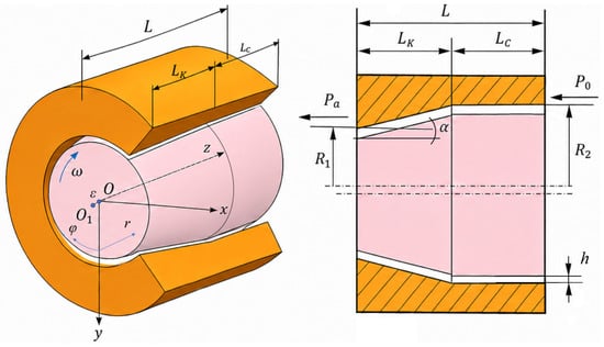
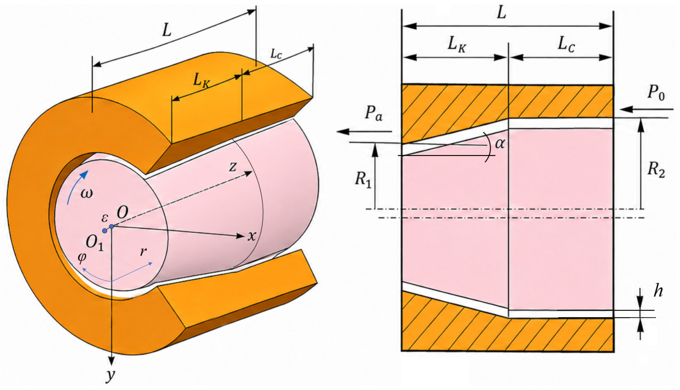
The conical–cylindrical bearing (CCB) under consideration consists of two components: a conical section and a cylindrical section. Modeling a CCB requires consideration the flow of a lubricant in a channel of length L and initial clearance h0, formed by a bearing and a uniformly rotating conical shaft. In this case, the conical and cylindrical parts of the bearing having lengths LK and LC proportionally contribute to the creation of the load capacity. The design and main geometric parameters of the CCB under consideration are illustrated in Figure 1.
Figure 1.
Design and main geometric parameters of a CCB.
The bearing is lubricated by an incompressible Newtonian fluid, which is supplied to the friction region in the axial direction from the cylindrical part under pressure p0, while at the opposite end of the bearing there is an ambient pressure pa. Hydrodynamic pressure in the bearing occurs in the presence of eccentricity ε which occurs when the geometric center of the shaft O1 is displaced from the center of the bearing O thereby forming confusor and diffuser regions. The pressure distribution in the lubricant film is described by a modified Reynolds equation. In this study, it is presented in a cylindrical coordinate system and is written in static form, that is, without taking into account the effect of lubricant film squeezing. The inertial component of the lubricant flow is also omitted, and the flow regime is assumed to be laminar. The modified Reynolds equation can be written in the following form for the cylindrical and conical sections:
where is the angular velocity; is the viscosity of the lubricant; and φ are radial and angular coordinates; p is the pressure in the fluid film; R1 and R2 are the minimum and maximum radius of the conical part of the shaft; h is the film thickness; and the indices c and k indicate the cylindrical and conical parts of the bearing, respectively—i.e., hc is the film thickness function for the cylindrical part, and hk is the film thickness function for the cylindrical part. These functions are defined as follows [29]:
where X1 and X2 are the coordinates of the shaft center in the bearing; is the cone angle; is the initial radial clearance; and the parameter is calculated as:
A rigid connection between the cylindrical and conical parts of a bearing is established by the equality of hc and hk functions along the line of their conjugation, i.e., on the surface of the bearing in a section perpendicular to its longitudinal axis with coordinate z = Lk:
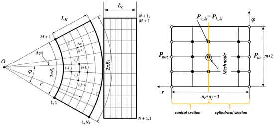
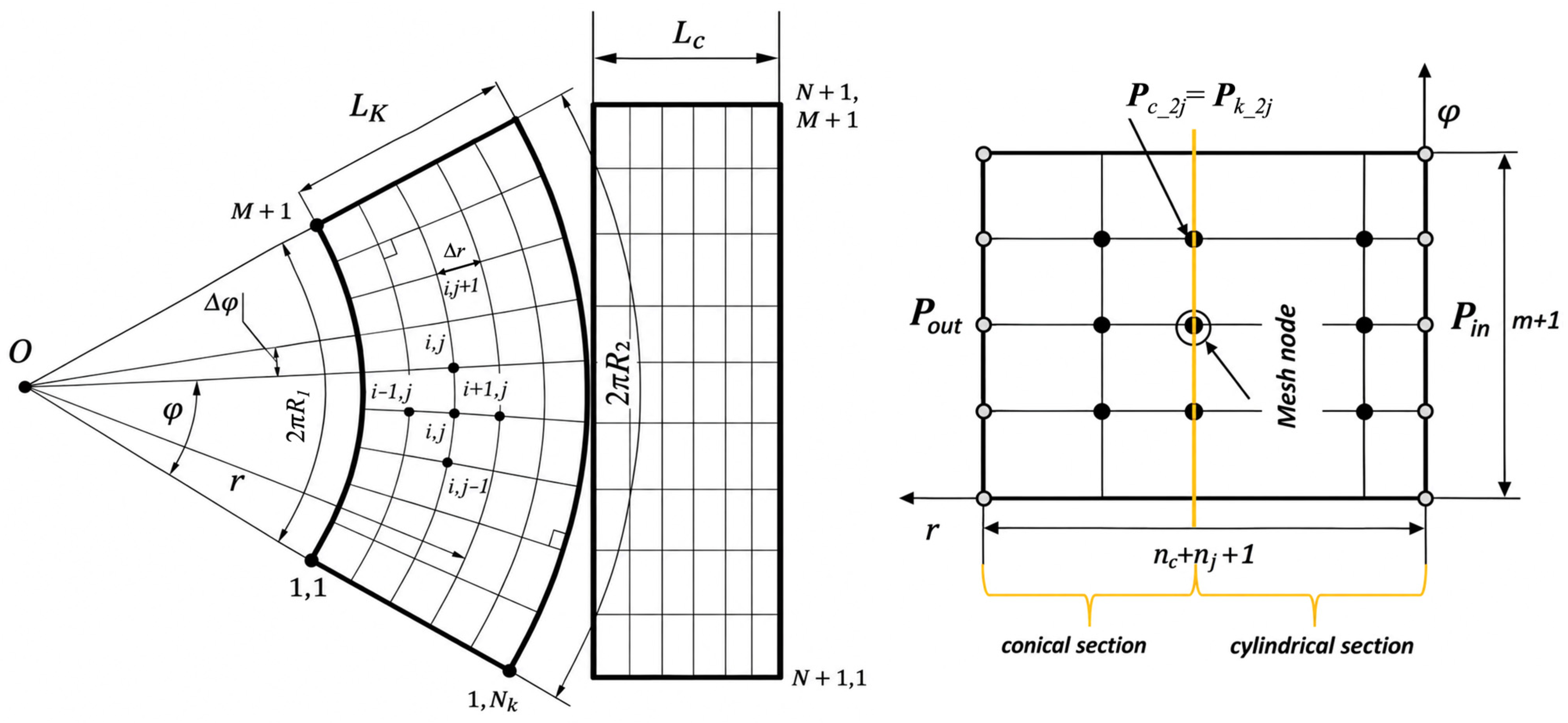
The numerical solution of Equations (1)–(5) was performed using the finite difference method and the MatLab R2020b software package. Known pressures p0 and pa at the bearing ends were used as boundary conditions. A standard Gumbel method was utilized in the numerical solving procedure to take into account the cavitation phenomena. Expression (6) is also used among the boundary conditions in the numerical solution of Equations (1)–(5), which is a specific feature of modeling of CCBs under consideration. A single unified lubricant mesh was also used in the calculation procedure to connect the conical and cylindrical parts of the bearing without repeating the boundary conditions for each bearing component, as demonstrated in Figure 2. Accounting for the variable mesh pitch in the conical part of the bearing was ensured by using Equation (4). This approach ensures the continuity of the pressure field and lubricant flow across the interface [30].
Figure 2.
Scheme of the mesh of the CCB’s surfaces of for numerical calculation.
The considered CCB model is valid for the laminar flow regime of the lubricant, characterized by the Reynolds number values Re < 2000–2200, which is calculated as follows:
where ρ is the lubricant density, and U is the circumferential speed of the bearing surface.
Based on the pressure field obtained by solving the Reynolds equation, the hydrodynamic forces on the corresponding coordinate axes can be calculated integrally using the following formulas:
Depending on the selected limits of integration of the pressure distribution according to Equations (8)–(10), the reactions of the conical and cylindrical parts of the bearing can be calculated separately.
The radial and axial load capacities of the bearing Wr and Wa can be calculated using the following formulas:
The radial load capacity of the conical and cylindrical parts of the bearing is calculated separately as follows:
An important feature of considered CCBs is that the lubricant is supplied along its axis, so the consumption depends mainly on the distribution of the gap:
where is the pressure gradient along the bearing axis.
The lubricant flow rate along with the heat generation power in the fluid film determines the temperature rise at the bearing outlet [31]:
where is lubricant temperature rise, is power of viscous friction in the fluid film, is the lubricant heat capacity, and is the lubricant density.
Power losses during bearing operation are determined by the heat generated in the lubricant film due to viscous friction caused by shear stresses:
where is the shear stress in the lubricant film:
The dynamic coefficients of the bearing, namely the stiffness (K) and damping (C) coefficients, were calculated using the classical small perturbation method [32]. According to its provisions, when the shaft is in an equilibrium position (X0, Y0, Z0), small displacements ΔX, ΔY, and ΔZ are added to this position in turn, and the new bearing forces are calculated by solving the Reynolds equations. The stiffness and damping coefficients are found as the ratio of the change in force to the displacement and velocity that caused it, respectively:
where ΔRi is the change in the i-th component of the force caused by a small perturbation of the position Δ or the velocity along the j-th coordinate. Since the CCB provides reactions not only in the radial but also in the axial direction, the results of the calculations of the dynamic coefficients are presented in the form of 3 × 3 matrices with three direct coefficients on the main diagonal and cross coefficients in the remaining positions:
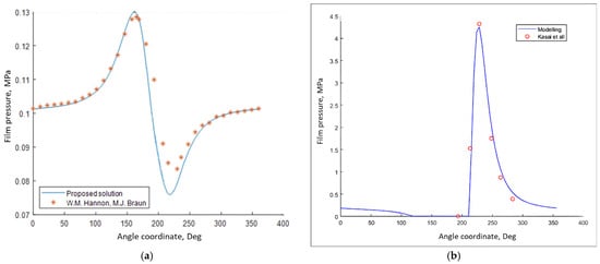
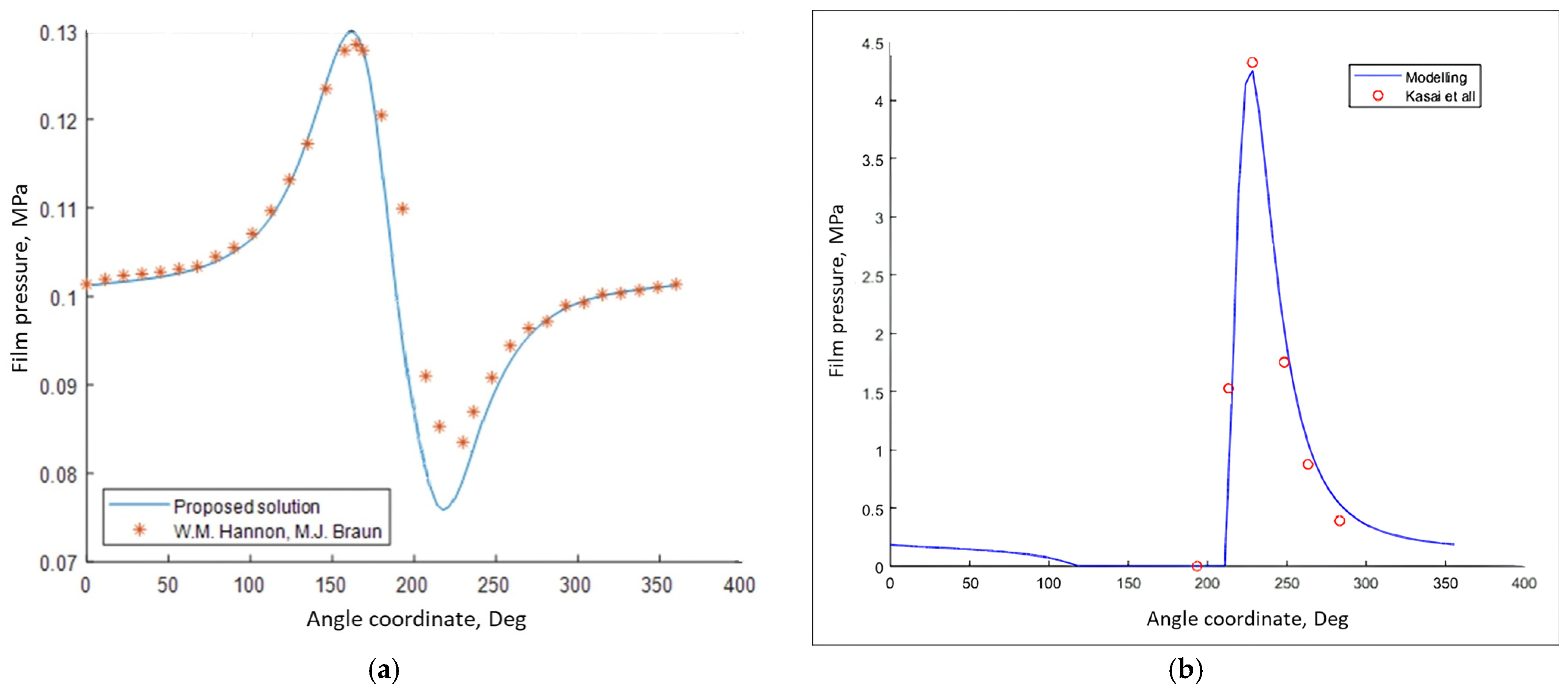
The validity of the simulation results obtained using the developed model was verified by comparing the calculated pressure distributions with the experimental results. In particular, the pressure distribution in the conical section of the bearing was compared with the experimental results of Hannon and Braun [33]. For this purpose, a model of the conical bearing was reproduced with the following parameters: R1 = 70 mm, R2 = 76 mm, L = 51 mm, .7, h0 = 76 µm, n = 10,000 rpm. A comparison of the simulated pressure distribution along the bearing centerline with the experimental data is shown in Figure 3a. The results of the modeling of the lubricant film of the cylindrical part of the bearing were compared with the experimental results of Kasai et al. [34]. For this purpose, a cylindrical hydrodynamic bearing with the following parameters was modeled: R1 = 60 mm, L = 74 mm, .7, h0 = 100 µm, n = 5000 rpm. The comparison results for the cylindrical part with the experimental data are shown in Figure 3b.
Figure 3.
Comparison of calculated and experimental results on cross-sections of pressure distributions along the bearing centerline: (a) for the conical part, with the results of Hannon and Braun [33]; (b) for the cylindrical part, with the results of Kasai et al. [34].
The graphs show good agreement between the results. The pressure prediction error of the developed model does not exceed 2–4% for most of the pressure distributions examined; the largest difference does not exceed 8% in the diffuser region of the conical bearing clearance, making a negligible contribution to the overall accuracy of the model. Since this study examines bearing characteristics calculated based on the pressure distribution in the lubricant film, the presented verification results allow us to consider the model used adequate, and the results obtained using it reliable for the research problems addressed.
3. Results
3.1. Numerical Results
3.1.1. Static Characteristics of CCB
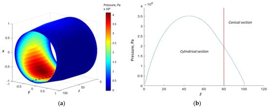
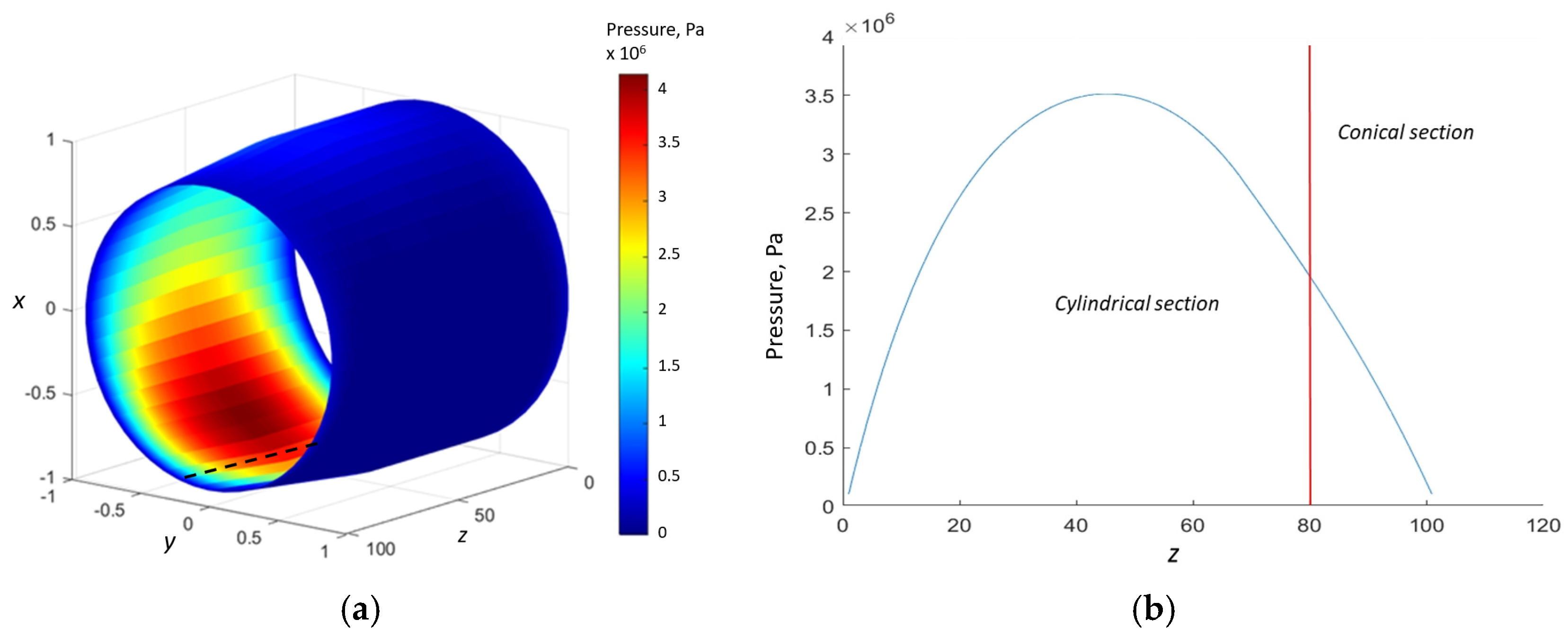
Numerical solution of Equations (1)–(5) using the finite difference method, as described in the previous section, allows us to obtain the pressure distribution in the bearing. Figure 4 shows a simulated typical pressure distribution diagram for a CCB with the following parameters: R1 = 15 mm, R2 = 20 mm, L = 36 mm, LC = 12 mm, .5, h0 = 50 µm, n = 5000 rpm, and a grid size of 100 × 60 elements. Figure 4a presents a spatial view of the pressure distribution in the lubricant film, and Figure 4b shows in more detail the two-dimensional pressure profile along the longitudinal line (indicated by a black dashed line in Figure 4a) formed by the cross-section of the bearing by a vertical plane through its longitudinal axis.
Figure 4.
Typical pressure distribution in CCB: (a) spatial view; (b) pressure profile at the vertical section of the bearing (black dashed line in (a)).
As can be seen, the transition from the conical to the cylindrical section of the bearing does not cause any sudden pressure changes, indicating that there is no significant resistance to the lubricant flow in this region during under axial supply conditions. This characteristic of the CCB can be considered valid, at least as long as the lubricant flow in the film remains laminar, i.e., as long as the Reynolds number, according to Equation (7), remains within the range of 2000–2200. For the CCB configuration under consideration, this corresponds to a shaft rotation speed of up to 20,000–21,000 rpm.
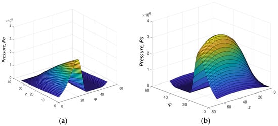
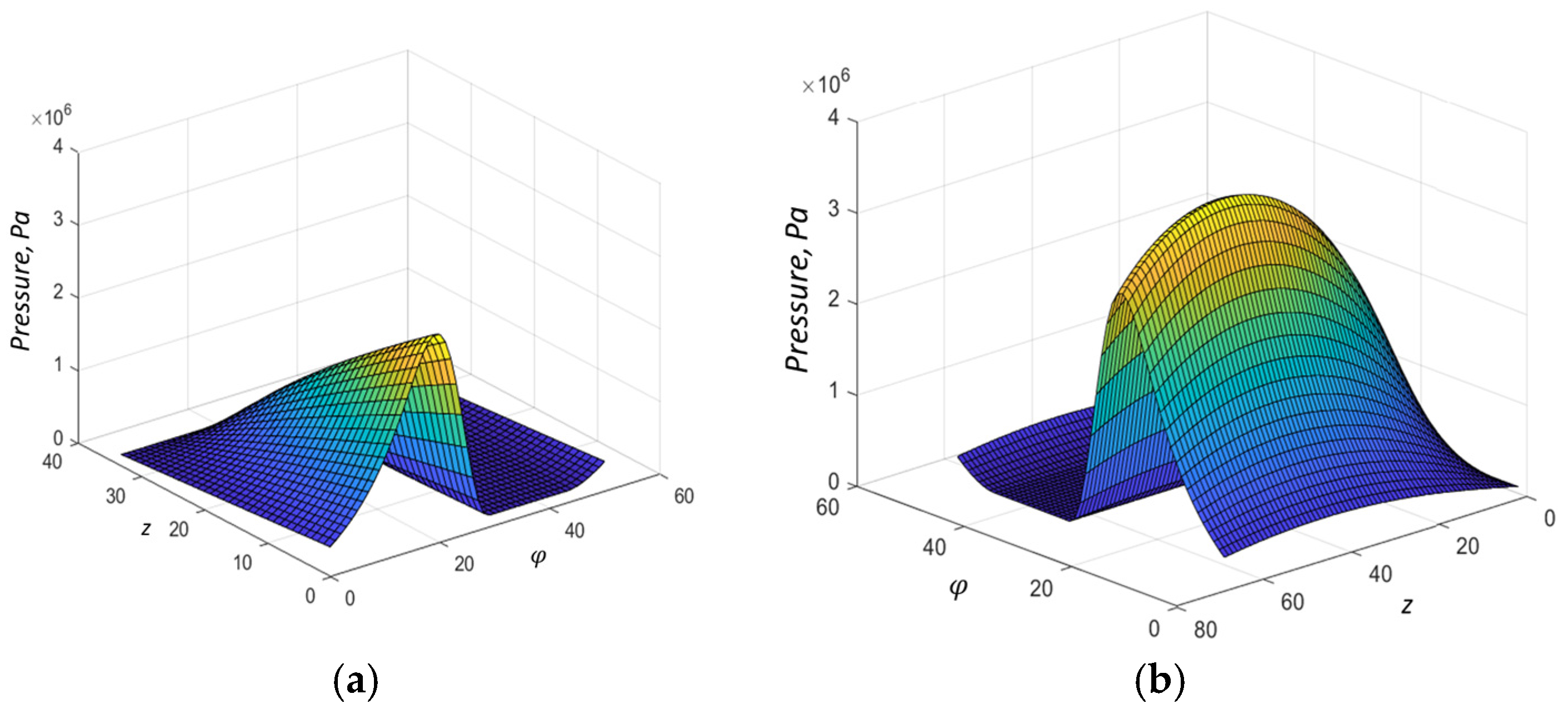
Figure 5 shows the pressure distribution in more detail, separately for the conical and cylindrical sections of the CCB.
Figure 5.
Pressure distribution in the CCB: (a) conical part; (b) cylindrical part.
The diagrams show that the pressure peak is shifted toward the cylindrical section of the bearing. This result is consistent with the structure of the simulated CCB configuration, in which the horizontal dimension of the cylindrical section LC is twice the length LK of the conical section. Furthermore, with increasing the shaft eccentricity in the bearing and in the absence of axial shaft displacement, the normal clearance in the conical section decreases slowly than in the cylindrical section, leading to an accelerated pressure increase in the latter.
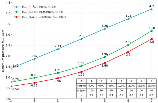
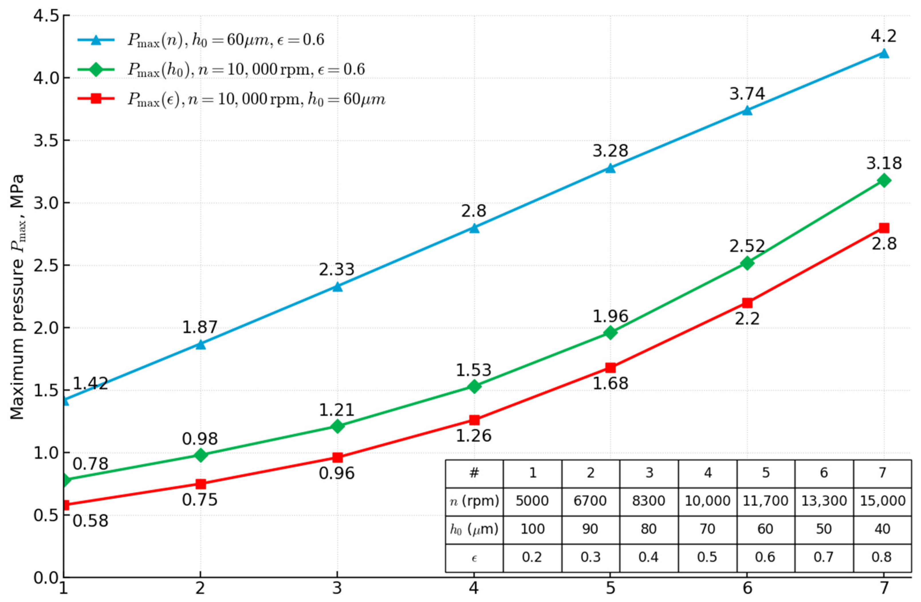
The diagram in Figure 6 shows how the maximum value of the CCB lubricant film pressure varies depending on its various geometric and operating parameters, namely, rotation speed n, initial clearance h0, and eccentricity ε. Each of these parameters had seven different gradations, the values of which are presented in the table in Figure 7.
Figure 6.
Peak pressure value in CCB with various parameters.
Figure 7.
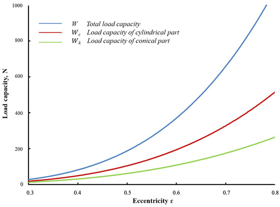
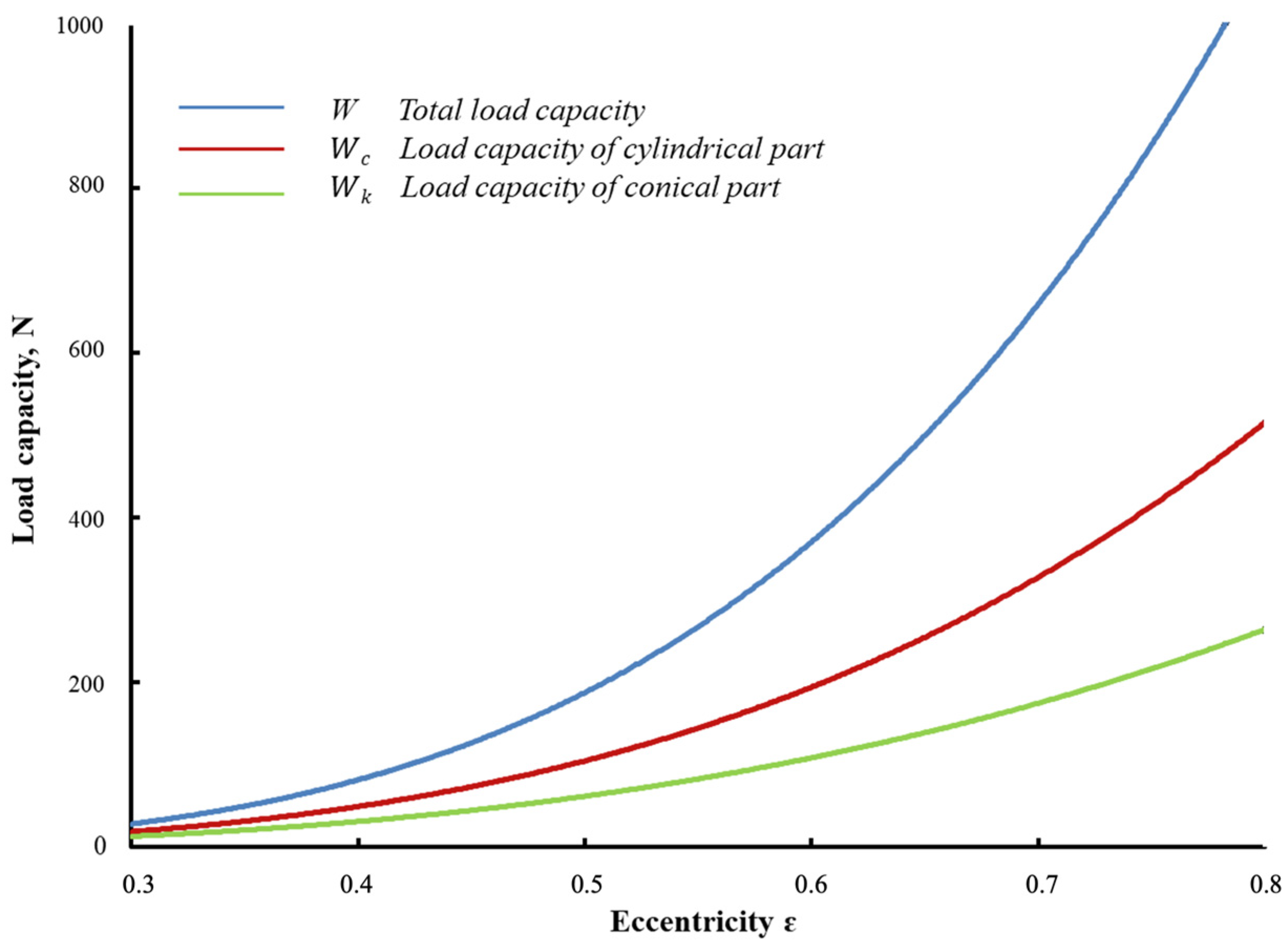
Dependence of the load capacity W and its components origin from the conical (Wk) and cylindrical (Wc) parts of CCB on the shaft eccentricity.
The maximum pressure in the lubricant film depends linearly on the shaft rotation speed and increases exponentially with increasing eccentricity and decreasing initial clearance. The shown relationships correspond to the principles of hydrodynamic lubrication theory, and the combination of conical and cylindrical sections in a single bearing does not introduce any noticeable distortions.
Based on the obtained data on the pressure distribution in the CCB, its load capacity was calculated and analyzed under various operating conditions using Formulas (9)–(12). Figure 7 shows the dependence of the CCB’s load capacity on the eccentricity ε, while also dividing the total value W into its conical and cylindrical components.
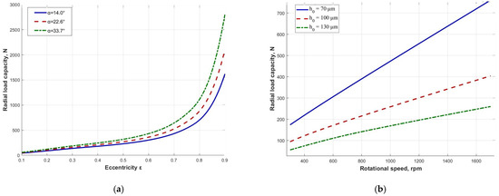
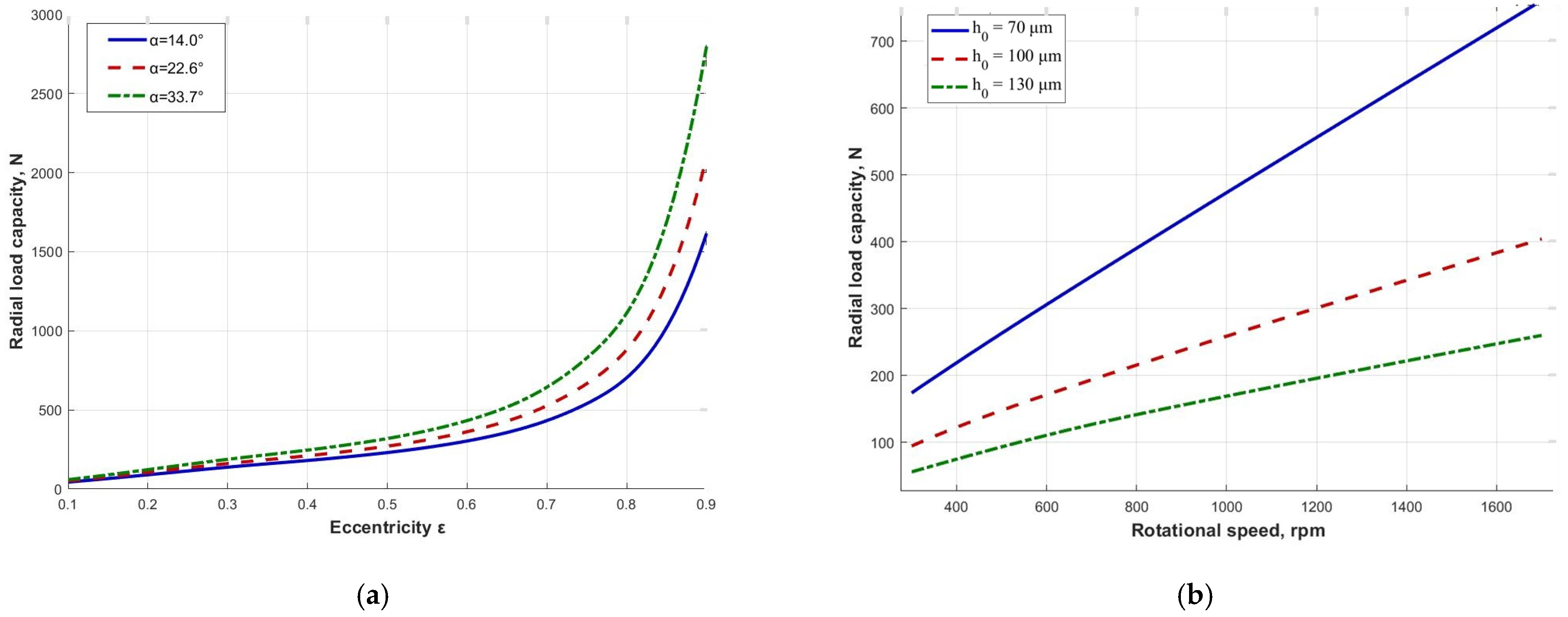
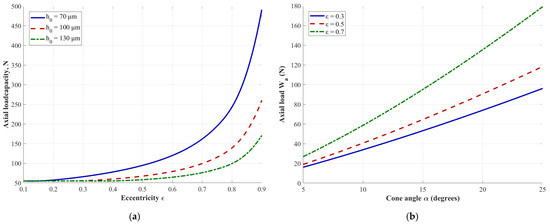
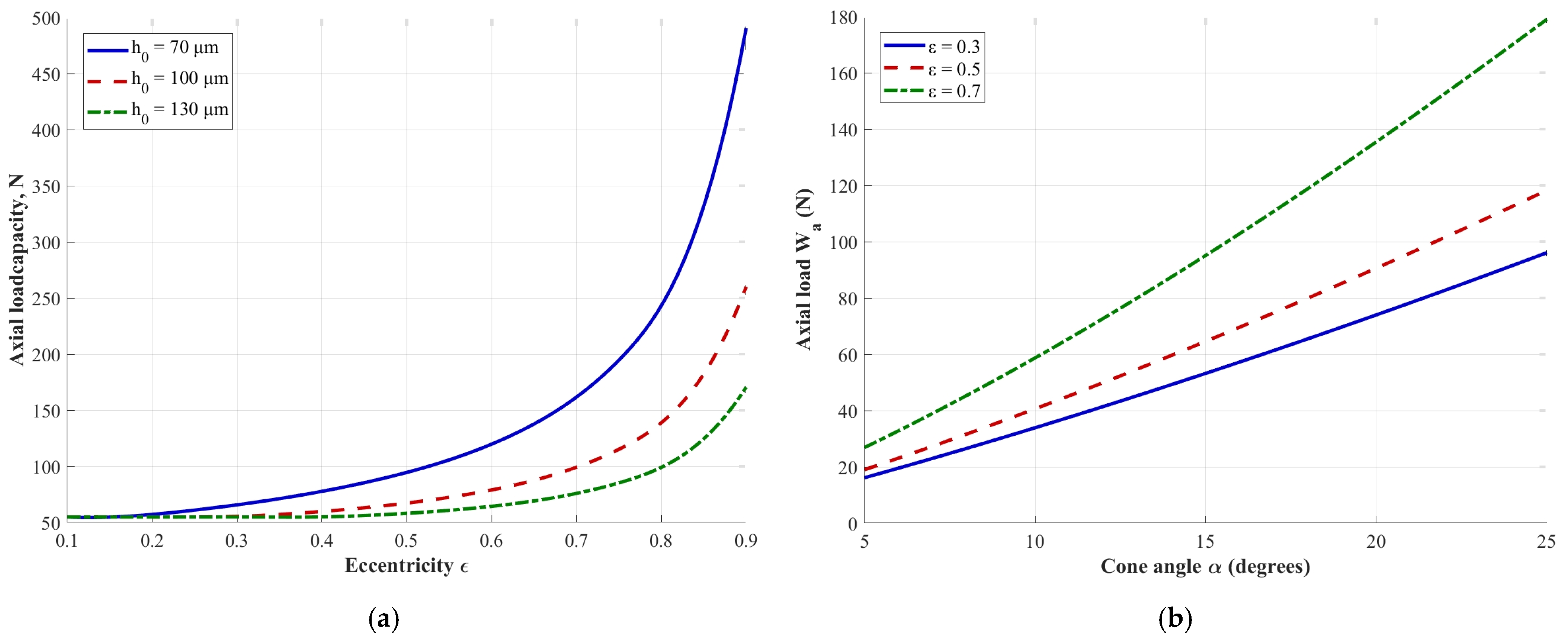
The results in Figure 7 provide a general characteristic of the CCB load capacity, which is nonlinear and increases significantly with increasing the shaft eccentricity. It should be noted that the graphs in Figure 7 show the full load capacity of the full CCB, while the conical part generates both radial and axial forces. Therefore, a more comprehensive analysis of the load capacity’s dependence on key influencing factors, such as the shaft speed, its relative eccentricity, radial clearance, and the bearing cone angle, was conducted. Graphs relating these factors to the radial load-carrying capacity Wr, are shown in Figure 8, and those relating to the axial load-carrying capacity Wa are shown in Figure 9.
Figure 8.
Dependence of radial load capacity Wr on: (a) eccentricity rate; (b) rotation speed.
Figure 9.
Dependence of axial load capacity Wa on: (a) eccentricity rate; (b) cone angle.
Figure 8a shows a nonlinear exponential relationship between Wr and the eccentricity rate ε, with a sharp increase in Wr in the region ε > 0.6. As α increases from 14° to 33.7°, the ratio Lc/L decreases, which increases the length of the cylindrical part, so Wr increases slightly. Figure 8b shows a nearly linear relationship between Wr and the rotational speed, which corresponds to the provisions of hydrodynamic theory. A decrease in h0 from 130 μm to 70 μm increases Wr approximately twofold at N = 1000 rpm.
Figure 9a demonstrates that the clearance h0 significantly influences Wa, with a reduction in clearance from 130 to 70 µm providing a more than 2.5-fold increase in axial load capacity. Figure 9b shows that the relationship between Wa and the cone angle α is relatively linear; its change within the considered limits provides a multiple increase in axial load capacity, confirming the decisive role of this design parameter in the CCB’s ability to withstand such loads.
In this context, the ratio of the radial and axial load capacity of the CCB is noteworthy, as the ability to combine them in a single unit is the prerequisite for moving away from traditional thrust-radial rotor support designs. Thus, according to the data in Figure 9b, increasing the cone angle α from 15° to 25° nearly doubles the bearing’s axial load capacity. At the same time, as the results in Figure 8a show, a comparable change in α reduces the radial load capacity by no more than 20%, which is ensured by the presence of a pronounced cylindrical section in this configuration. Thus, the design under consideration allows the support to be adapted to the required axial loads over a fairly wide range, while significantly reducing the impact on the radial load capacity.
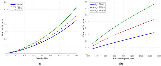
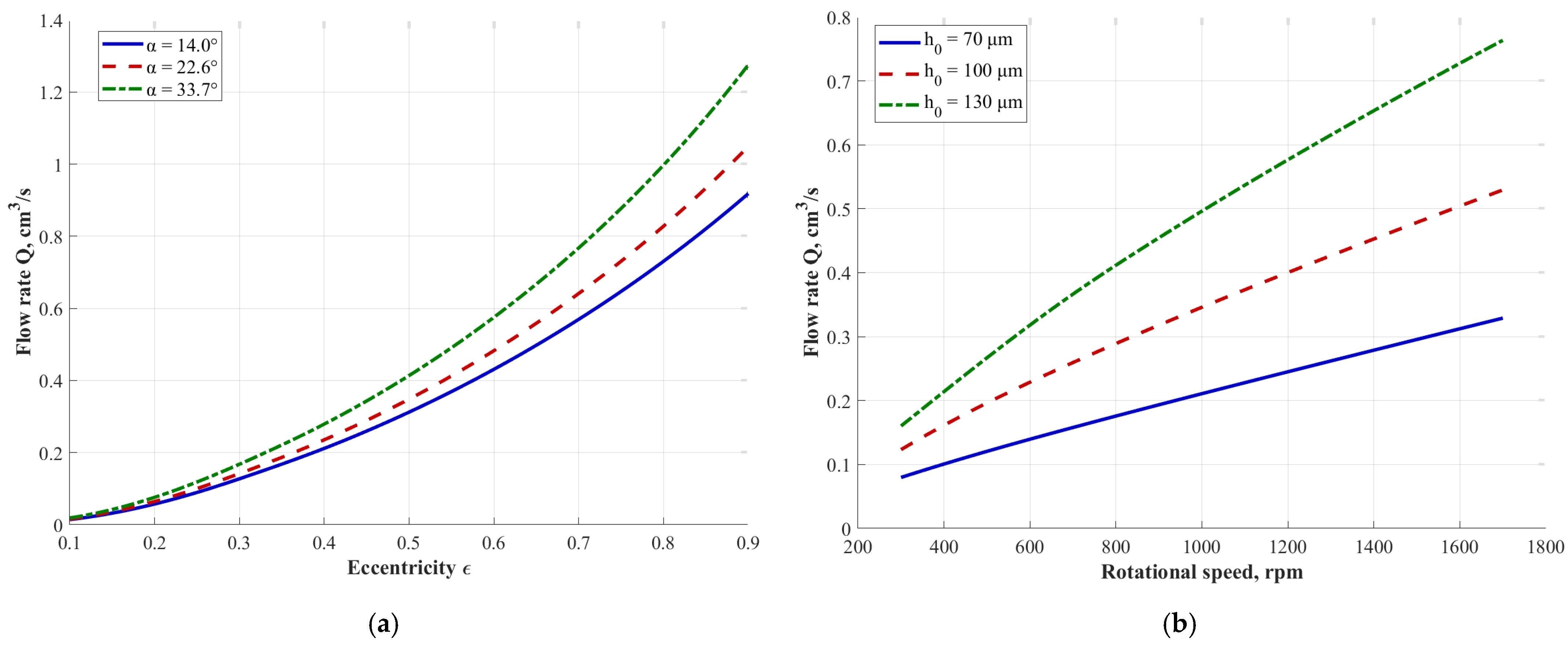
The two graphs in Figure 10 analyze the volumetric lubricant flow through the CCB. The calculations were carried out for the case of lubrication with water at a temperature of 20 °C, the lubricant was supplied from the cylindrical side of the bearing with a pressure of p0 = 0.2 MPa, while there is no back pressure from the conical part; i.e., the ambient pressure is equal to the atmospheric pressure.
Figure 10.
Dependence of the lubricant (water) flow rate Q on: (a) eccentricity rate; (b) rotation speed.
Due to the axial lubricant supply in the system under consideration, the flow rate depends mainly on the bearing clearance distribution, as follows from Equation (15). Figure 10a shows the nonlinear relationship between QΔp and the eccentricity ε for three cone angles α, indicating that the absolute value of the flow rate decreases with increasing α. As α increases from 14° to 33.7°, the ratio Lc/L decreases, which increases the length of the cylindrical section, so the flow rate increases slightly. Figure 10b shows a directly proportional, almost linear relationship between QΔp and the rotational speed for three clearance values, where the flow rate increases with increasing h0, since a large clearance provides less hydraulic resistance.
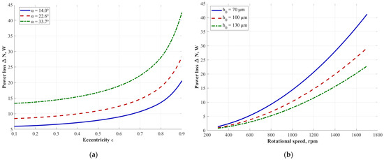
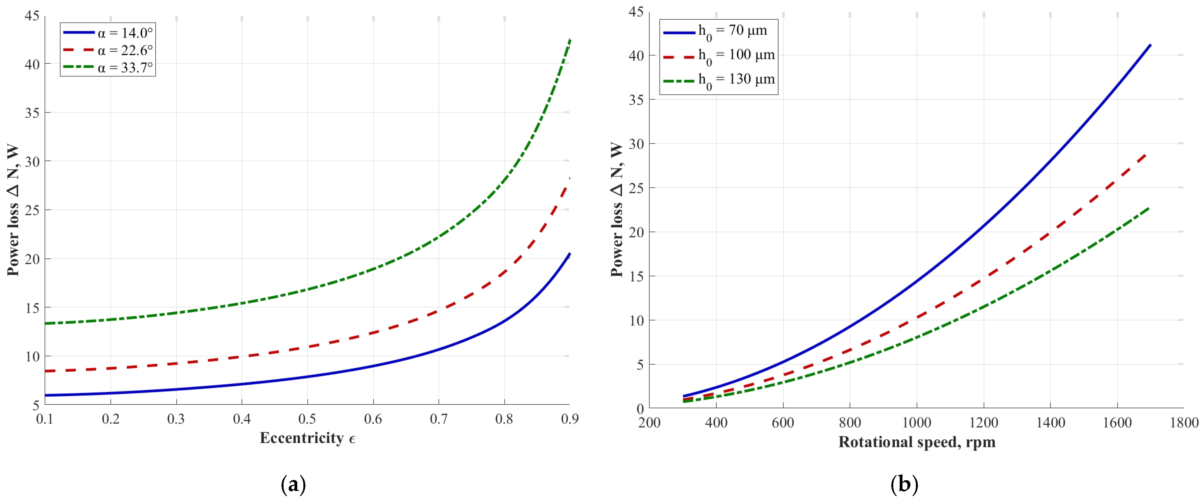
Friction mode during the steady-state operation of CCB is purely hydrodynamic due to the complete separation of the surfaces by a lubricating film. Friction in the bearing under these conditions has viscous nature and provided by the shear of the film layers relative to each other; power losses for overcoming this friction is calculated using Equation (17). The magnitude of frictional power losses in CCB for different design and operating parameters is shown in Figure 11.
Figure 11.
Dependence of power losses in the lubricant film on: (a) eccentricity rate; (b) rotation speed.
Figure 11a shows the nonlinear relationship between ΔN and ε at three cone angles α, indicating that ΔN increases with α due to the larger friction surface area. As α increases from 14° to 33.7°, the ratio Lc/L decreases, which increases the length of the cylindrical section, so ΔN decreases slightly. Figure 11b shows the quadratic dependence of ΔN on rotational speed at three clearance values. As h0 decreases from 130 μm to 70 μm, ΔN increases significantly, especially in the high-speed region.
Under the conditions considered, the temperature increase at the bearing outlet, calculated according to Equation (16), will be in the order of 2–10 °C, which for most cases is an optimal indicator and can serve as evidence of a high-quality balance between energy costs for pumping lubricant, heat removal from the friction zone and high-quality lubrication of the bearing.
3.1.2. Dynamic Characteristics of CCB
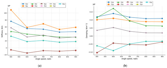
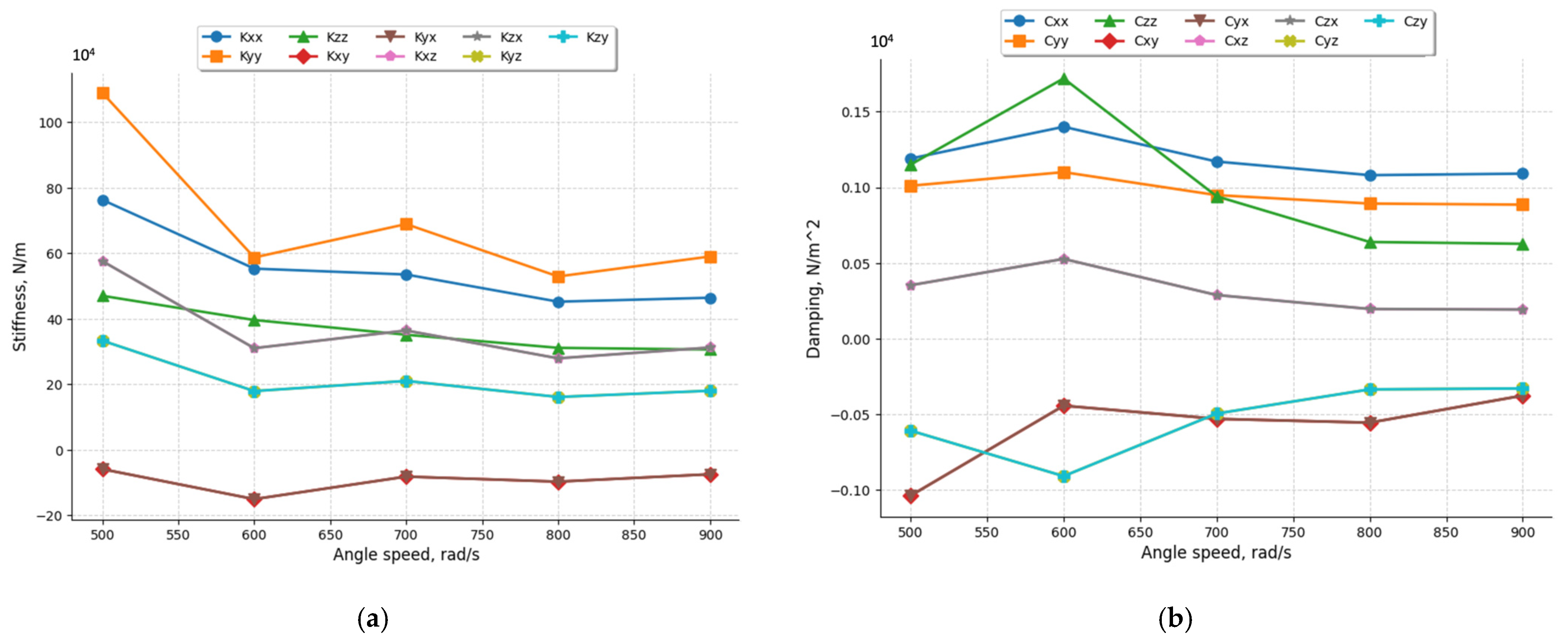
Dynamic characteristics of CCBs under consideration have been obtained to assess their tendency to induce instabilities arising from fluid film forces. Conventional small perturbations method was used in this study to calculate matrices of stiffness and damping coefficients at various rotation speed which allows us to evaluate their change during the acceleration or deceleration of a rotor. Calculations were performed for a bearing with the parameters R1 = 15 MM, R2 = 20 MM, L = 36 MM, Lk = 18 MM, and h0 = 50 µm, and water was used as the lubricant. The calculation results are shown in Figure 12.
Figure 12.
Variation in dynamic characteristics of CCBs under variation in the rotation speed: (a) stiffness coefficients; (b) damping coefficients.
The calculation results show that the direct stiffness coefficients Kxx, Kyy and Kzz gradually decrease with increasing shaft angular velocity. The cross stiffness coefficients associated with axial shaft displacements also behave similarly. However, the cross stiffness coefficients associated with radial displacements, namely Kxy and Kyx, change significantly less over the same range of rotational speeds.
Direct damping coefficients Cxx, Cyy and Czz generally also decrease slightly with increasing rotational speed, but to a lesser extent than the corresponding stiffness coefficients. Conversely, the cross damping coefficients associated with axial shaft displacements show a slight tendency to increase under the same conditions.
Analyzing the obtained dynamic characteristics of the CCB, it should be noted that the values of both the direct stiffness and damping coefficients significantly exceed the cross coefficients. As noted in the introduction, research has shown that their relationship is related to the bearing’s tendency to create instabilities; this issue will be analyzed in more detail in the Discussion section.
4. Discussion
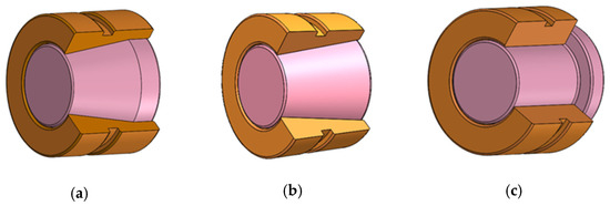
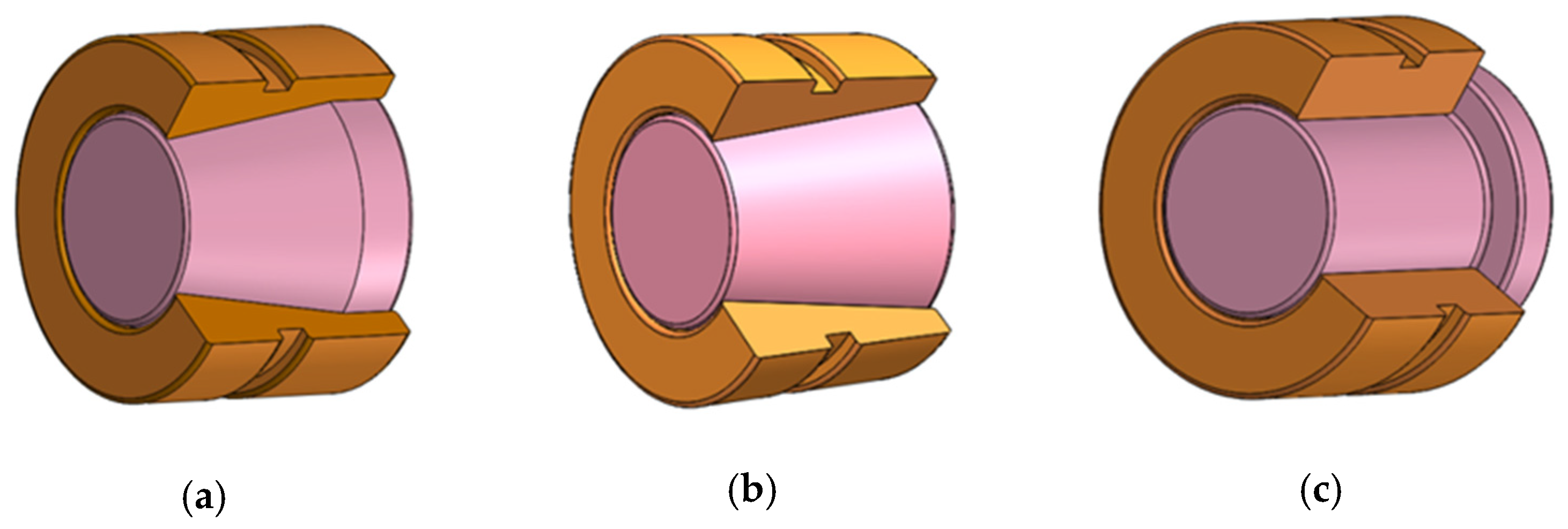
Finally, for a more comprehensive comparison of the hybrid CCB with other types of fluid film bearings capable of supporting axial and radial loads, a comparative modeling of key integral characteristics was conducted for three types of radial–axial bearings: conical–cylindrical (CCB), conical (CB), and composite thrust–journal (TJB) bearings. A pure conical bearing can essentially be considered as a CCB with a degenerate cylindrical section, while a TJB thrust bearing can be considered as a CCB with a 90-degree cone angle. A schematic of the bearings considered is shown in Figure 13.
Figure 13.
Different types of radial–axial bearing considered in the comparison: (a) conical–cylindrical bearing (CCB); (b) conical bearing (CB); (c) thrust–journal bearing (TJB).
Given the differences in the bearings’ design, the analysis procedure was designed with several specific features to ensure a more objective and comprehensive comparison of the bearings’ characteristics. First, since the more efficient CCB layout in terms of weight and dimensions appears to be one of their key advantages, the comparison was conducted for designs with comparable dimensions, primarily length L and diameters (R1 and R2). Second, a group of solutions with key design parameters varying within specified ranges were analyzed instead comparing any individual specific configuration of each bearing to account for potential variability among the solutions and to generalize the analysis. Thus, during the analysis, the relative eccentricity and angular velocity of the rotor, as well as the value of the bearing clearance, were varied, and the bearing capacity and friction power losses as key integral characteristics were analyzed after basic statistical processing of the results. The parameters of the simulated bearings are presented in Table 1. Water was used as the lubricant in all cases, and the temperature was assumed to be steady at 20 °C. For the TJB case, the minimum and maximum radii R1 and R2 correspond to the inner and outer diameters of the thrust part of the bearing, and the cylindrical part has a constant radius equal to the minimum R1. The thrust part of the bearing is also designed with eight individual fixed pads with an inclination angle of 0.4°.
Table 1.
Parameters of the radial–axial bearings under comparison.
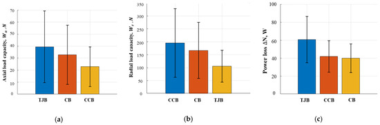
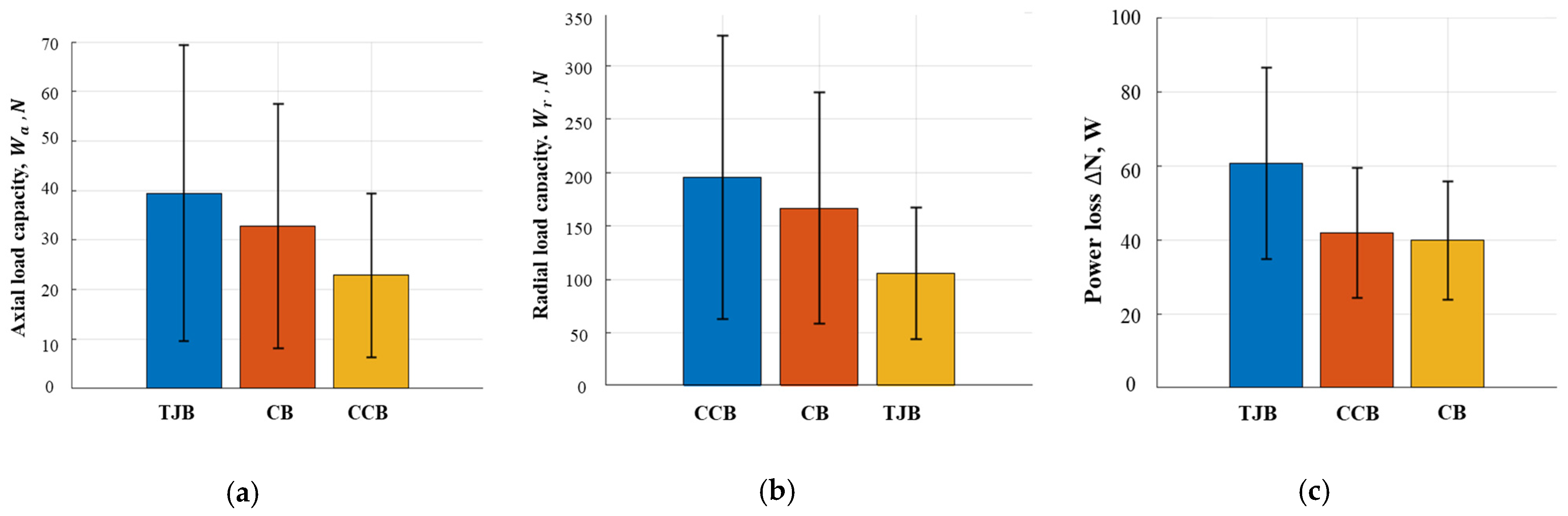
The range and step size of the variable parameters shown in Table 1, including relative eccentricity ε, angular velocity ω, and bearing clearance h0, thus provide 75 combinations, each corresponding to a separate design solution. The radial Wr and axial Wa loads, as well as the power losses in the lubricant film due to viscous friction ΔN, were calculated for each variant, after which the average value was calculated for each bearing type. The calculation results are presented in the bar graphs in Figure 14, where the column values describe the average parameter value, and the error bars in each column display the range of variations from the minimum to the maximum value.
Figure 14.
Comparison of variation in key integral characteristics of CCB, CB and TJB: (a) axial load capacity Wa; (b) radial load capacity Wr; (c) power loss for viscous friction Ploss.
As the simulation results show, TJBs with comparable dimensions and key design parameters provide the highest axial load-carrying capacity, primarily due to the use of inclined pads in the thrust section, which are necessary to generate hydrodynamic force in this type of shaft-bearing connection. The axial load capacity of CBs and CCBs is ensured by the conical surface, and its larger surface area in CBs provides an advantage in this parameter over the CCBs studied. Moreover, CCBs provide, on average, a higher radial load capacity than CBs and TJBs due to their pronounced cylindrical support surface. The radial load capacity of TJBs, with the same bearing dimensions, is, on average, the lowest. This is explained by the smaller support area per cylindrical section, since it has a constant radius equal to the minimum R1, whereas in CCBs the cylindrical section is designed with a larger radius R2.
In terms of power losses due to viscous friction in the lubricant film, which is directly related to shaft rotational resistance and the subsequent increase in lubricant film temperature, TJBs exhibit significantly higher losses, averaging up to 50% under the conditions examined, compared to CBs and CCBs. The latter two bearing types demonstrate a negligible difference in this regard, not exceeding 5–8% under the conditions examined. In this context, it is also worth noting that the geometric configuration of TJBs requires more complex lubricant supply schemes to separate friction areas compared to CBs and CCBs, which can utilize simple axial lubrication scheme, thereby reducing the demands on the lubrication system.
The obtained results illustrate the specificity of the bearing types examined in terms of their key integral characteristics, such as multidirectional load capacity and friction within the lubricant film. Thus, CBs and CCBs are generally more suitable for machines with slightly lower axial loads compared to TJBs, which have greater axial load capacity having similar dimensions. However, they provide significantly lower radial load capacity compared to CBs and CCBs, and increasing it would require increasing the weight and dimensions of the bearing, inevitably further increasing frictional power losses and degrading the system’s thermal performance. Furthermore, as noted above, TJBs are already more demanding of the lubrication system, which must have a more complex structure than can be utilized for CBs and CCBs. When comparing the last two bearing types, the balance in load capacity is predictably shifted toward the axial direction for CBs and toward the radial direction for CCBs, while differences in viscous friction power losses remain insignificant. Moreover, both CBs and CCBs have reduced lubrication system requirements compared to TJBs. Furthermore, additional differences between CBs and CCBs lie in their dynamic characteristics.
The above calculation results for the dynamic coefficients of CCBs demonstrate the potential of this bearing type to provide more stable operation of the rotor system compared to CBs. This is particularly due to the previously noted relationship between the direct and cross-dynamic coefficients, primarily related to the radial shaft displacements within the bearing. Specifically, the direct coefficients significantly exceed the cross coefficients in CCBs. This indicates that the normal forces generated by the lubricant film significantly exceed the tangential forces, which often lead to the occurrence of instabilities during rotor rotation, such as oil whip and oil whirl.
Furthermore, the obtained results clearly demonstrate that CCBs are capable of ensuring rotor acceleration without reversing the stiffness and damping coefficients, at least within the considered range of operating conditions and design parameters. Considering that some known studies associate such situations with the occurrence of unstable operating modes of FFBs, as mentioned above, this creates additional prerequisites for developing more stable solutions based on CCBs compared to conical FFBs. This stabilizing effect is likely due to the presence of the cylindrical section of the bearing, for which the problem of instability is generally less acute than for CBs.
While discussing the obtained results, it should be emphasized once again that they are valid for CCB operating modes with laminar lubricant flow in the fluid film, characterized by a quite smooth transition in the pressure distribution between its conical and cylindrical parts. A transition to turbulent flow, for example, with increasing the rotational speed, may be associated with qualitative changes in the bearing characteristics, which could be the subject of further research.
Another aspect worthy of consideration in comparing the bearings is their manufacturing technology. The CCBs under consideration have a relatively simple design, similar to CBs, and therefore employ a similar manufacturing technology. The use of CNC machine tools ensures a relatively low complexity and cost of the manufacturing process, which is an advantage for implementing this technology in real-world applications.
At the same time, it should be noted that the issue of stability of rotor motion on CCBs is considered in this study in its basic formulation, highlighting general trends in the dynamic behavior of CCBs. The presented results suggest the potential for providing more stable operation of CCBs compared to other types of radial–axial bearing systems, such as CBs. Given the diversity of possible solutions and their application conditions, the study of CCB dynamic stability requires a more comprehensive analysis and will be explored in greater detail through further research, including relevant theoretical parametric studies and physical experiments. The motivation for continuing this research is the results already obtained, which demonstrate the advantages in terms of weight, size, and design simplicity of the rotor system compared to other types of radial–axial rotor supports.
5. Conclusions
Hybrid conical–cylindrical bearings (CCBs), as demonstrated by the results of the study, are a promising solution for machines requiring improved weight, size, and simplification of the rotor support system, including the lubrication system. Their key advantage is the ability to accommodate both axial and radial loads in a single, structurally simple unit, ensuring more stable rotor behavior and improved support system energy efficiency compared to other types of fluid film thrust–journal bearings (TJBs).
The present study was conducted using a developed steady-state, isothermal hydrodynamic lubrication model based on the Reynolds equation considering laminar flow conditions of an incompressible Newtonian lubricant. The finite difference method was employed to solve the governing equation and obtain the pressure distribution in the lubricant film. This numerical framework, validated against experimental data from the literature, was applied to systematically investigate the integral and dynamic characteristics of CCBs over a range of design parameters (cone angle, bearing clearance) and operating conditions (rotational speed, eccentricity ratio). The key findings arising from this analysis are summarized below:
- -
- Conical–cylindrical design allows for flexible adjustment of the bearing’s axial load capacity, which can vary multiple times with an almost linear dependence on the selected cone angle, while the radial load capacity changes significantly more slowly, with a factor of about 0.2, due to the presence of a cylindrical section.
- -
- A significant increase in the load capacity of CCBs is accompanied by a moderate increase in power losses due to viscous friction and a concomitant increase in the lubricant temperature at the bearing outlet, which does not exceed 2–10 °C for water lubrication in the considered range of conditions, indicating the effectiveness of the lubrication regime.
- -
- The abovementioned lubrication regime can be achieved with a relatively simple lubrication system with end-face lubrication, as opposed to a more conventional design with separate thrust and journal bearing sections of TJBs, each of which requires a separate lubricant supply.
- -
- Having comparable dimensions and key design parameters, CCBs also provide, in addition to design simplification, lower (up to 50%) viscous friction losses and associated heat generation compared to TJBs.
- -
- CCB design can ensure the dominance of direct stiffness and damping coefficients over cross coefficients, as well as the absence of a change in the sign of the latter during shaft acceleration, which indicates a potentially lower tendency of CCBs to the occurrence of instabilities induced by the lubricant film compared to conventional conical bearings.
These encouraging results motivate further research on CCBs, including an expanded and in-depth analysis of their dynamic behavior under realistic conditions using both numerical and experimental methods. This should provide a comprehensive understanding of the stability limits of CCB-based rotor systems and contribute to the creation of a comprehensive theoretical basis for the transfer of such solutions to industry and the improvement of the performance of modern machines.
Author Contributions
Conceptualization, D.S. and R.Z.; methodology, D.S. and T.H.N.; software, T.H.N.; validation, D.S., S.L. and R.Z.; formal analysis, D.S., T.H.N. and R.Z.; investigation, D.S. and T.H.N.; resources, Z.C., S.L. and R.Z.; data curation, T.H.N.; writing—original draft preparation, D.S. and T.H.N.; writing—review and editing, D.S. and T.H.N.; visualization, D.S., R.Z. and T.H.N.; supervision, Z.C. and S.L.; project administration, Z.C. and S.L.; funding acquisition, R.Z. and Z.C. All authors have read and agreed to the published version of the manuscript.
Funding
This work was funded by the National Natural Science Foundation of China (NSFC) [Grant No. 12502054], China Postdoctoral Science Foundation [Grant No. 2024M764171], National Science and Technology Major Project [Grant no. 2017-IV-0010-0047-JX], Natural Science Foundation of Heilongjiang Province [Grant no. YQ2025E011].
Data Availability Statement
The data can be made available on request.
Conflicts of Interest
The authors declare no conflicts of interest.
Nomenclature
| α | bearing cone angle, deg |
| [C] | damping matrix, N·s/m |
| CXX, CXY, … | elements of damping matrix (damping coefficients), N·s/m |
| cT | lubricant heat capacity, J/(kg·K) |
| ε | relative eccentricity, dimensionless |
| h | clearance function (general), m |
| hc | clearance function of the cylindrical part, m |
| hk | clearance function of the conical part, m |
| h0 | initial radial clearance, m |
| [K] | stiffness matrix, N/m |
| KXX, KXY, … | elements of stiffness matrix (stiffness coefficients), N/m |
| L | bearing total length, m |
| LC | cylindrical part length, m |
| LK | conical part length, m |
| μ | dynamic viscosity, Pa·s |
| Nfr | friction power loss, W |
| n | rotational speed, rpm |
| ω | angular velocity, rad/s |
| p | pressure, Pa |
| p0 | inlet (supply) pressure, Pa |
| pa | ambient pressure, Pa |
| flow rate, m3/s | |
| r, φ | cylindrical coordinates, m, deg |
| rc, rk | bearing radius in cylindrical and conical parts, m |
| R1, R2 | minimum and maximum bearing radii, m |
| x, y, z | Cartesian coordinates, m |
| RX, RY, RZ | bearing forces, N |
| Re | Reynolds number, dimensionless |
| ρ | fluid density, kg/m3 |
| Tfr | friction torque, N·m |
| T | temperature, °C |
| τ | shear stress, Pa |
| W | load capacity (bearing capacity), N |
| Wa, Wr | axial and radial load capacity, N |
| Wrc, Wrk | radial load capacity of cylindrical and bearing part, N |
| X, Y, Z | coordinates of journal center position in the bearing, m |
Abbreviations
The following abbreviations are used in this manuscript:
| CCB | Conical–cylindrical bearing |
| CB | Conical bearing |
| TJB | Thrust–journal bearing |
| FFB | Fluid film bearing |
References
- Kalita, W.; Rodkiewicz, C.M.; Kennedy, J.S. On the Laminar Flow Characteristics of Conical Bearings (Part I: Analytical Approach). J. Tribol. 1986, 108, 53–58. [Google Scholar] [CrossRef] [Scilit]
- Murthy, T.S.R. Analysis of Multi-Scallop Self-Adjusting Conical Hydrodynamic Bearings for High Precision Spindles. Tribol. Int. 1981, 14, 147–150. [Google Scholar] [CrossRef] [Scilit]
- Gangrade, A.K.; Phalle, V.M.; Mantha, S.S. Performance Analysis of a Conical Hydrodynamic Journal Bearing. Iran. J. Sci. Technol. Trans. Mech. Eng. 2019, 43, 559–573. [Google Scholar] [CrossRef] [Scilit]
- Kempepatil, R.; Hiremath, A.G.; Hanumagowda, B.N.; Patil, J.; Tawade, J.V.; Khan, M.I. Influence of Magneto-Hydrodynamic and Couple Stress Squeeze Film Lubrication on Conical Bearing—A Slip Velocity Model. Alex. Eng. J. 2024, 106, 735–742. [Google Scholar] [CrossRef] [Scilit]
- Chen, Y.; Shi, X.; Wang, X.; Wang, H.; Yu, C.; Sun, Y. Multi-Objective Analysis Design of Spiral Groove Conical Bearing Considering Cavitation Effects. Results Eng. 2022, 15, 100582. [Google Scholar] [CrossRef] [Scilit]
- Salem, E.; Khalil, M.F. Thermal and Inertia Effects in Externally Pressurized Conical Oil Bearings. Wear 1979, 56, 251–264. [Google Scholar] [CrossRef] [Scilit]
- Kennedy, J.S.; Sinha, P.; Rodkiewicz, C.M. Thermal Effects in Externally Pressurized Conical Bearings with Variable Viscosity. J. Tribol. 1988, 110, 201–211. [Google Scholar] [CrossRef] [Scilit]
- Prabhu, T.J.; Ganesan, N. Analysis of Multirecess Conical Hydrostatic Thrust Bearings Under Rotation. Wear 1983, 89, 29–40. [Google Scholar] [CrossRef] [Scilit]
- Li, S.; Ao, H.; Jiang, H.; Chen, L.; Korneev, A. Lubrication Characteristics of Deep Cavity Hybrid Conical Bearing. J. Harbin Inst. Technol. 2013, 45, 60–66. [Google Scholar]
- Singh, V.; Rajput, A.K. Piezoviscous-Polar Lubrication of Capillary Compensated Hybrid Conical Undulated Journal Bearing. Tribol. Int. 2023, 186, 108588. [Google Scholar] [CrossRef] [Scilit]
- Pawar, S.R.; Phalle, V.M.; Handikherkar, V.C.; Patil, S.S. The Static Performance Variation of Orifice Compensated Worn Hybrid Conical Bearing with Journal Speed. In Proceedings of the International Conference on Tribology, TRIBOINDIA-2018, Mumbai, India, 13–15 December 2018. [Google Scholar]
- Phalle, V.M.; Pawar, S.R.; Patil, S.S. Effect of Speed on the Performance Characteristics of Non-Recessed Worn Hybrid Conical Journal Bearing for Different Semi Cone Angles. In Proceedings of the ASME 2018 International Mechanical Engineering Congress and Exposition (IMECE2018), Pittsburgh, PA, USA, 9–15 November 2018. [Google Scholar]
- Rowe, W.B. Conical Hydrostatic Journal Bearings for High Speeds. Proc. Inst. Mech. Eng. Part J J. Eng. Tribol. 2021, 235, 808–819. [Google Scholar] [CrossRef] [Scilit]
- Khalil, M.F.; Kazzab, S.Z.; Ismail, A.S. Performance of Externally Pressurized Conical Thrust Bearing Under Laminar and Turbulent Flow Conditions. Wear 1993, 166, 147–154. [Google Scholar] [CrossRef] [Scilit]
- Gangrade, A.K.; Phalle, V.M.; Mantha, S.S.; Siddiquee, A.N. Influence of Eccentricity Ratio on Stability Performance of Hydrodynamic Conical Journal Bearing. J. Phys. Conf. Ser. 2019, 1240, 012115. [Google Scholar] [CrossRef] [Scilit]
- Li, Y.; Zhang, D.; Duan, F. Dynamic Characteristics of Opposed-Conical Gas-Dynamic Bearings. Ind. Lubr. Trib. 2020, 72, 415–425. [Google Scholar] [CrossRef] [Scilit]
- Pawar, S.R.; Phalle, V.M.; Sawant, P.K. Influence of Wear on the Cross-Coupled Dynamic Coefficients and Threshold Speed of Conical Hybrid Fluid Film Bearing. J. Inst. Eng. India Ser. C 2023, 104, 1173–1180. [Google Scholar] [CrossRef] [Scilit]
- Shinde, A.; Pawar, P.; Shaikh, P.; Wangikar, S.; Salunkhe, S.; Dhamgaye, V. Experimental and Numerical Analysis of Conical Shape Hydrodynamic Journal Bearing with Partial Texturing. Procedia Manuf. 2018, 20, 300–310. [Google Scholar] [CrossRef] [Scilit]
- Khakse, P.G.; Phalle, V.M.; Mantha, S.S. Comparative Performance of a Nonrecessed Hole-Entry Hybrid/Hydrostatic Conical Journal Bearing Compensated with Capillary and Orifice Restrictors. Tribol. Ind. 2016, 38, 133–148. [Google Scholar]
- Singh, V.; Rajput, A.K. Effect of Pocket Orientation on PVP Lubricated Hybrid Conical Journal Bearing System. Tribol. Int. 2024, 197, 109858. [Google Scholar] [CrossRef] [Scilit]
- Awad, H.; Saber, E.; Abdou, K.M.; Dajani, S. Stability Analysis of Hydrodynamic Journal Bearings with Variable Axial Geometrical Configuration Using Titanium Dioxide Nanoparticles as Lubricant Additives. Sci. Rep. 2026, 16, 13389. [Google Scholar] [CrossRef] [Scilit] [PubMed]
- Kumar, A.; Sharma, S.C. Textured Conical Hybrid Journal Bearing with ER Lubricant Behavior. Tribol. Int. 2019, 129, 363–376. [Google Scholar] [CrossRef] [Scilit]
- Singh, A.; Sharma, S.C. Behaviour of Conical Porous Hybrid Journal Bearing Operated with MHD Lubricant Considering Influence of Surface Irregularities. Tribol. Int. 2022, 174, 107730. [Google Scholar] [CrossRef] [Scilit]
- Rajani, C.B.; Hanumagowda, B.N.; Shigehalli, V.S. Effects of Surface Roughness on Conical Squeeze Film Bearings with Micropolar fluid. J. Phys. Conf. Ser. 2018, 1000, 012079. [Google Scholar] [CrossRef] [Scilit]
- Zuo, X.; Wang, J.; Yin, Z.; Li, S. Comparative Performance Analysis of Conical Hydrostatic Bearings Compensated by Variable Slot and Fixed Slot. Tribol. Int. 2013, 66, 83–92. [Google Scholar] [CrossRef] [Scilit]
- Rolink, A.; Jacobs, G.; Schröder, T.; Keller, D.; Jakobs, T.; Bosse, D.; Lang, J.; Knoll, G. Methodology for the Systematic Design of Conical Plain Bearings for Use as Main Bearings in Wind Turbines. Forsch. Ingenieurwes. 2021, 85, 629–637. [Google Scholar] [CrossRef] [Scilit]
- Euler, J.; Jacobs, G.; Loriemi, A.; Jakobs, T.; Rolink, A.; Röder, J. Scaling Challenges for Conical Plain Bearings as Wind Turbine Main Bearings. Wind 2023, 3, 485–495. [Google Scholar] [CrossRef] [Scilit]
- Elsharkawy, A.A. Lubricant Additives Effects on the Hydrodynamic Lubrication of Misaligned Conical–Cylindrical Bearings. Lubr. Sci. 2007, 19, 213–229. [Google Scholar] [CrossRef] [Scilit]
- Nicoletti, R. Comparison Between a Meshless Method and the Finite Difference Method for Solving the Reynolds Equation in Finite Bearings. J. Tribol. 2013, 135, 044501. [Google Scholar] [CrossRef] [Scilit]
- LeVeque, R.J. Finite Difference Methods for Ordinary and Partial Differential Equations: Steady-State and Time-Dependent Problems; Society for Industrial and Applied Mathematics: Philadelphia, PA, USA, 2007. [Google Scholar]
- Thomsen, K.; Klit, P. A Study on Compliant Layers and Its Influence on Dynamic Response of a Hydrodynamic Journal Bearing. Tribol. Int. 2011, 44, 1872–1877. [Google Scholar] [CrossRef] [Scilit]
- Lund, J.W. Dynamic Coefficients for Fluid Film Journal Bearings. In Vibration and Wear in High Speed Rotating Machinery; NATO ASI Series; Springer: Dordrecht, The Netherlands, 1990; Volume 174, pp. 605–616. [Google Scholar] [CrossRef] [Scilit]
- Hannon, W.M.; Braun, M.J. Numerical Solution of a Fully Thermally Coupled Generalized Universal Reynolds Equation (GURE) and Its Application. Part 1: Conical Bearings. Tribol. Trans. 2007, 50, 540–557. [Google Scholar] [CrossRef] [Scilit]
- Kasai, M.; Fillon, M.; Bouyer, J.; Jarny, S. Influence of Lubricants on Plain Bearing Performance: Evaluation of Bearing Performance with Polymer-Containing Oils. Tribol. Int. 2012, 46, 190–199. [Google Scholar] [CrossRef] [Scilit]

Disclaimer/Publisher’s Note: The statements, opinions and data contained in all publications are solely those of the individual author(s) and contributor(s) and not of MDPI and/or the editor(s). MDPI and/or the editor(s) disclaim responsibility for any injury to people or property resulting from any ideas, methods, instructions or products referred to in the content. |
© 2026 by the authors. Licensee MDPI, Basel, Switzerland. This article is an open access article distributed under the terms and conditions of the Creative Commons Attribution (CC BY) license.