


Abstract
Permanent Magnet Synchronous Motors (PMSMs) are widely employed in electric vehicle (EV) propulsion systems because of their high efficiency, high power density, and superior dynamic performance. The performance of field-oriented control (FOC)-based PMSM drives strongly depends on accurate tuning of the proportional–integral (PI) controllers governing the speed and current loops. Conventional tuning approaches often optimize a single performance index and therefore fail to simultaneously enhance the dynamic behavior of all control loops. This paper proposes a multi-error Integral of Time-weighted Absolute Error (ITAE)-based optimization framework for simultaneous tuning of the PI controllers by minimizing a composite objective function that incorporates the time-weighted absolute errors of the rotor speed, q-axis current, and d-axis current. To validate the effectiveness and optimizer independence of the proposed framework, five metaheuristic optimization algorithms—Genetic Algorithm (GA), Particle Swarm Optimization (PSO), Gray Wolf Optimizer (GWO), Gazelle Optimization Algorithm (GOA), and White Shark Optimization (WSO)—are evaluated under identical optimization settings. MATLAB/Simulink simulations are performed for reference-speed tracking, load disturbance rejection, and variable-speed operation. The results demonstrate that the proposed optimization framework consistently improves tracking accuracy and dynamic response regardless of the selected optimizer, while WSO provides the best overall performance. In the variable-speed tracking scenario, WSO achieved the lowest RMSE of 0.96 rad/s and the minimum ITAE value of 0.1716, confirming its effectiveness as the most suitable optimizer for the proposed framework in high-performance PMSM drive applications.
1. Introduction
Permanent Magnet Synchronous Motors (PMSMs) have become a popular choice for the propulsion system of an electric vehicle (EV) due to the following properties: high efficiency, high torque density, a compact structure, and a fast dynamic response [1,2]. Field-oriented control (FOC) is one of the control strategies that has proven to be the most effective control method for PMSM drives and is especially so in the highly demanding application of EVs. FOC can transform three-phase stator currents into a rotating d–q reference frame, enabling independent flux and torque control and thus achieving the required high efficiency and excellent dynamic response for automotive propulsion [3]. In EVs, quick acceleration and conserving energy are of primary importance, and this precision is crucial. But to maintain peak performance under the changing operating conditions found in a vehicle (e.g., changing temperatures, changing loads), accurate calibration is required. As a result, research in recent years has focused on the improvement of FOC using intelligent tuning techniques to guarantee good speed regulation over the whole drive cycle [4,5]. Recent studies have demonstrated that metaheuristic optimization techniques can effectively automate controller parameter tuning, leading to improved dynamic performance, enhanced disturbance rejection, and increased robustness in electric motor drive systems, thereby emphasizing the growing importance of intelligent optimization methods for high-performance drive applications [6,7].
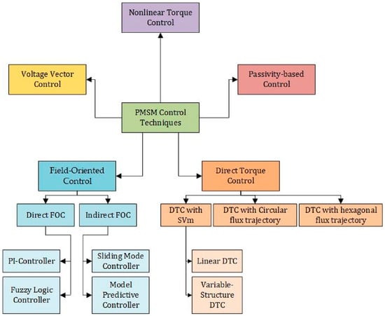
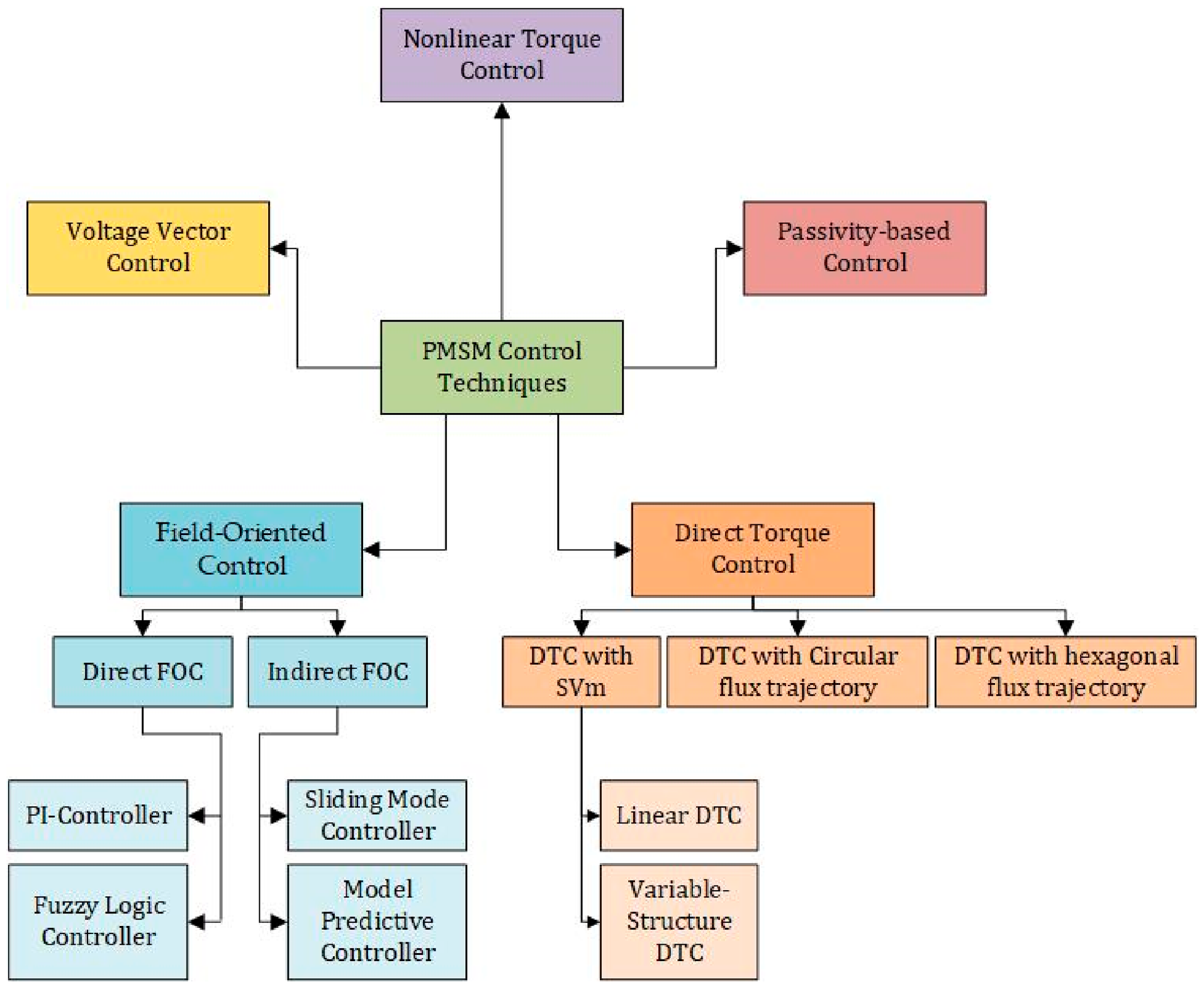
Figure 1 presents a general classification of PMSM control strategies reported in the literature, where most of the works in EV applications are performed using FOC-based approaches because of their ability to decouple control of torque and flux, as well as their high efficiency and fast dynamic response.
Figure 1.
Classification of PMSM control techniques and the position of field-oriented control among advanced motor control strategies.
The proportional–integral (PI) controller still prevails in industrial applications for its speed and current control of PMSM drives due to its simplicity, easy implementation, and low computation load. However, traditional PI controllers are very sensitive to the proper choice of controller gains [8]. For EV applications, improperly tuned PI controllers can lead to high current oscillations, long speed settling times, high copper losses, and reduced efficiency of the drive [9,10]. To address these challenges, a significant amount of research has been conducted to propose optimization-based methods to fine-tune PI controller parameters in PMSM control systems [11,12].
Among the various control strategies shown in Figure 1, recent research has focused not only on developing intelligent optimization methods for automatic PI controller tuning but also on enhancing conventional PI-based FOC schemes through adaptive control techniques to improve robustness against parameter uncertainties and operating condition variations while preserving the simplicity and practicality of PI controllers [13,14].
Bio-inspired and swarm intelligence algorithms have been shown to be very successful in this field because they can solve problems that are nonlinear, multi-variable, and non-convex [15]. Previous studies [16] have shown that optimization techniques inspired by nature can substantially improve the speed regulation performance for PMSMs by optimizing the PI controllers of FOC. Although transient performance measures can provide insightful information, they do not completely represent the demands of an EV drive. In an EV application, these persistent tracking errors in rotor speed (and also stator currents) have a direct impact on energy efficiency, thermal stress, and torque smoothness. Errors in the q-axis current cause a reduction in torque production, while errors in the d-axis current from zero can cause a reduction in efficiency and may increase the chance of demagnetization [17]. For EV applications, the optimization criterion that is based on the explicit penalization of long-duration errors is more suitable for PMSM control [18,19]. Motivated by these considerations, this work proposes a unified ITAE-based multi-error optimization framework for the simultaneous tuning of PI controllers in the speed, q-axis current, and d-axis current control loops of an FOC-controlled PMSM drive. The proposed framework formulates the controller tuning task as a unified constrained optimization problem through a composite objective function that simultaneously minimizes the ITAE of the rotor speed, q-axis current, and d-axis current tracking errors. Since the proposed framework is independent of the optimization algorithm, it can be implemented using different metaheuristic techniques. To validate its effectiveness, five representative optimization algorithms (GA, PSO, GWO, GOA, and WSO) are investigated under identical operating conditions and performance criteria for electric vehicle applications.
The main contributions of this paper are summarized as follows:
- A unified multi-error ITAE-based optimization framework is proposed to formulate the simultaneous tuning of PI controllers in the speed, q-axis current, and d-axis current control loops of an FOC-controlled PMSM drive as a constrained optimization problem.
- The proposed optimization framework is formulated independently of the optimization algorithm, enabling different metaheuristic techniques to optimize the same objective function under identical optimization settings and performance criteria.
- Five representative metaheuristic optimization algorithms, namely GA, PSO, GWO, GOA, and WSO, are employed to validate the effectiveness of the proposed optimization framework under representative EV operating scenarios, including reference speed tracking, load disturbance rejection, and variable-speed operations.
- Comprehensive quantitative performance evaluation is conducted using tracking accuracy, disturbance rejection capability, electromagnetic torque characteristics, stator current behavior, and percentage improvements in RMSE, ITAE, and peak current to systematically assess the proposed optimization framework and identify the most effective optimization algorithm for the investigated PMSM drive.
The remainder of this paper will be organized into the following sections: In, the mathematical model of the PMSM and the adopted field-oriented control structure are presented. In, the PI controller tuning problem is formulated, and the proposed objective function is introduced. In, the investigated metaheuristic optimization algorithms and their implementation are described. The results of the simulations are presented and analyzed in or various operating scenarios. The conclusions are summarized in Section 6, providing directions for future research.
2. PMSM Model and Field-Oriented Control Scheme
To enable a systematic analysis of PI controller tuning for electric vehicle propulsion, this section establishes the mathematical model of the PMSM in the synchronous dq reference frame and defines the corresponding field-oriented control structure. The dq-frame representation allows decoupled control of electromagnetic torque and stator flux [20], which is essential for achieving high efficiency and a fast dynamic response in EV drive systems. The adopted FOC scheme employs cascaded PI controllers for rotor speed and stator current regulation, forming the control architecture upon which the optimization problem is formulated.
2.1. Mathematical Model of PMSM
The Permanent Magnet Synchronous Motor is a nonlinear, multi-variable system, characterized by strong coupling between its electrical and mechanical dynamics [21]. In this work, the PMSM model is expressed in the synchronous rotating reference frame (dq-frame) [22,23].
The electrical dynamics of the stator currents in the dq-frame are given by:
where and are the d-axis and q-axis stator currents, and are the corresponding control voltages, is the stator resistance, and are the stator inductances, is the permanent magnet flux linkage, and is the electrical angular speed, which can be calculated from (3).
where is the number of pole pairs, and is the mechanical speed.
The electromagnetic torque of a surface-mounted PMSM, where , is expressed as:
The mechanical dynamics of the rotor are described by:
where is the inertia moment, is the viscous friction coefficient, is the load torque, and is the rotor position.
2.2. Field-Oriented Control Structure
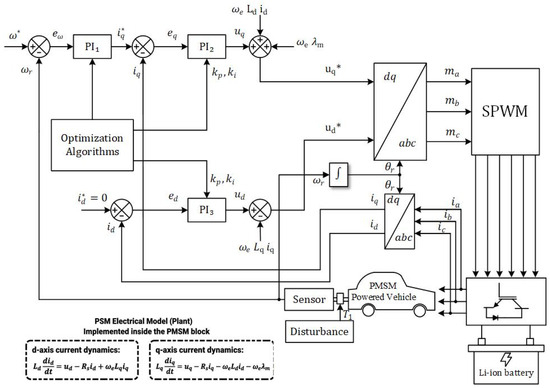
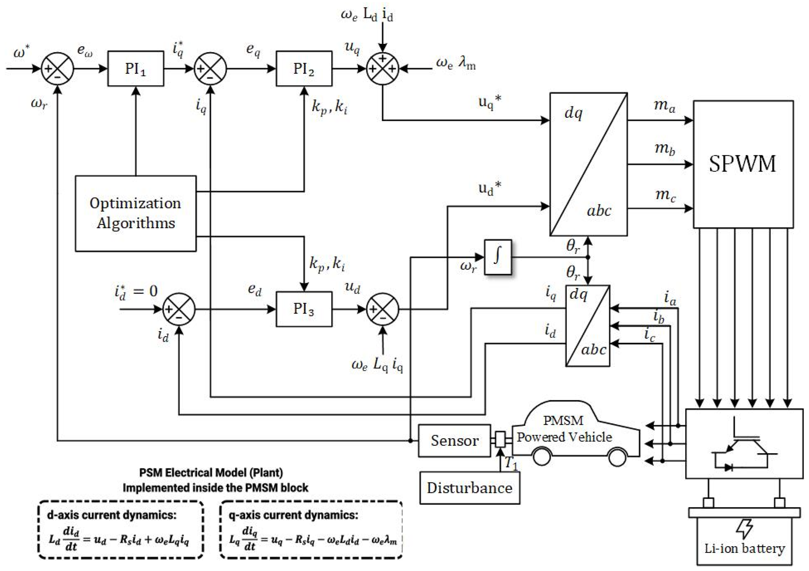
Field-oriented control is employed to decouple the torque and flux components of the PMSM, enabling independent control of the stator currents in the dq-frame. The adopted control structure consists of three cascaded PI controllers: one outer speed control loop and two inner current control loops, as shown in Figure 2. The d-axis reference current is fixed at zero to ensure efficient operation, while the q-axis current reference is generated by the speed PI controller.
Figure 2.
Block diagram of the FOC-based PMSM drive for electric vehicle applications.
2.3. Coordinate Transformations and SPWM Implementation
To achieve decoupled torque and flux control, the measured three-phase stator currents are first transformed into the stationary αβ reference frame using the Clarke transformation. Subsequently, the Park transformation converts the αβ components into the synchronous rotating dq reference frame according to the rotor electrical position. In this frame, the d-axis current controls the magnetic flux, whereas the q-axis current regulates the electromagnetic torque. After computing the voltage references and , the inverse Park transformation is applied to obtain the αβ voltages, followed by the inverse Clarke transformation to reconstruct the three-phase voltage references [24]. Finally, a Sinusoidal pulse-width modulation (SPWM) technique generates the switching signals required to drive the three-phase voltage source inverter.
2.4. Clarke Transformation
2.5. Park Transformation
2.6. Inverse Park Transformation
The resulting stationary reference-frame voltage components are subsequently transformed into three-phase voltage references and supplied to the SPWM inverter, where a high-frequency triangular carrier signal is employed to generate the gate pulses for the three-phase voltage source inverter, ensuring accurate realization of the commanded stator voltages.
The outer loop regulates the rotor speed by generating the reference q-axis current based on the speed tracking error:
where is the reference speed, and is the actual speed.
The inner current loops regulate the d-axis and q-axis currents using PI controllers. The d-axis reference current is set to zero () to ensure maximum torque per ampere operation and improved efficiency, which is particularly important for electric vehicle applications. The corresponding current tracking errors are defined as:
The outputs of the current PI controllers generate the voltage commands and , which are transformed back to the three-phase stationary reference frame and applied to the inverter using a pulse-width modulation technique.
This cascaded FOC structure allows precise regulation of speed and currents, while the performance of the overall system heavily depends on the proper tuning of the three PI controllers. Consequently, an efficient and robust optimization strategy is required to determine the optimal PI gains, as addressed in the following sections.
3. Problem Formulation and ITAE-Based Objective Function
This section formulates the PI controller tuning task for the FOC PMSM drive as a constrained optimization problem. The control objectives are expressed in terms of the rotor speed and stator current tracking errors, and an ITAE-based performance index is introduced to reflect efficiency-oriented requirements of electric vehicle applications.
3.1. Control Objectives
The primary control objective of an electric vehicle PMSM drive is to ensure accurate rotor speed tracking while maintaining efficient torque production and minimizing electrical losses. Within the adopted field-oriented control framework, these objectives translate into the following requirements:
- Precise tracking of the reference rotor speed to guarantee drivability and a dynamic response.
- Accurate regulation of the q-axis current to ensure proportional torque generation.
- Suppression of the d-axis current to zero in order to maximize efficiency and avoid unnecessary magnetic and copper losses.
These requirements must be satisfied simultaneously under nonlinear system dynamics, load torque disturbances, and operating conditions typical of electric vehicle propulsion systems. Therefore, the tuning of the PI controllers associated with the speed loop and the current loops is formulated as a multi-variable optimization problem.
Accordingly, the control objectives can be expressed as the simultaneous minimization of the rotor speed tracking error , q-axis current tracking error , and d-axis current tracking error . These error components constitute the basis of the proposed multi-error ITAE objective function presented in Section 3.2.
3.2. Error Definitions and EV-Oriented Performance Criteria
In electric vehicle propulsion systems, control performance directly influences drivability, energy efficiency, and thermal stress of the traction motor. Within the field-oriented control framework, three tracking errors are of primary importance: the rotor speed error, q-axis current error, and d-axis current error. These errors, respectively, reflect vehicle speed regulation accuracy, torque production quality, and efficiency of magnetic utilization.
The rotor speed tracking error is defined as:
where denotes the reference mechanical speed, and is the measured rotor speed.
Accurate regulation of the q-axis current is essential for proportional electromagnetic torque generation in PMSM drives. The corresponding tracking error is defined as:
To ensure maximum efficiency and avoid unnecessary magnetic losses, the d-axis reference current is set to zero for surface-mounted PMSMs. The d-axis current tracking error is therefore given by:
Simultaneous minimization of these three errors is required to achieve high-performance and energy-efficient operation under the variable load and speed conditions characteristic of electric vehicle driving cycles.
3.3. ITAE-Based Multi-Error Objective Function
In optimization-based controller tuning for PMSM drives, the selection of an appropriate performance index plays a critical role in determining both transient and steady-state behavior. Conventional indices such as the Integral of Squared Error (ISE) and the Integral of Absolute Error (IAE) have been widely used; however, recent studies in motor-drive control indicate that these criteria may not adequately reflect the operational requirements of electric vehicle traction systems [25]. The ISE criterion excessively penalizes large initial errors, which may lead to aggressive control actions and elevated current peaks, while the IAE criterion assigns equal importance to early and late errors, potentially resulting in slow convergence and prolonged steady-state deviations.
To address these limitations, this work adopts the Integral of Time-weighted Absolute Error (ITAE) as the performance index for PI controller tuning. The ITAE criterion assigns progressively increasing weight to tracking errors that persist over time, thereby promoting rapid error attenuation, improved damping of oscillatory behavior, and enhanced steady-state convergence. Recent PMSM drive studies have demonstrated that ITAE-based tuning leads to smoother speed and current responses and reduced steady-state oscillations compared to conventional error criteria [26].
In electric vehicle PMSM drives, prolonged speed and current tracking errors are particularly undesirable, as they increase copper losses, amplify torque ripple, and impose additional stress on the power electronic inverter. By emphasizing late-stage error suppression, the ITAE criterion aligns the controller tuning process with efficiency-oriented and reliability-driven objectives inherent to EV propulsion systems.
Accordingly, the proposed objective function is formulated as a weighted sum of the ITAE terms associated with the rotor speed, q-axis current, and d-axis current tracking errors:
where w1, w2, and w3 are weighting factors introduced to regulate the relative contribution of the rotor speed, q-axis current, and d-axis current tracking errors, respectively. These weighting factors account for the different magnitudes and control priorities of the three error components and enable the optimization process to assign an appropriate level of importance to each performance objective. The time-weighting factor further emphasizes errors that persist at later instants, thereby promoting rapid error attenuation and improved settling behavior. Consequently, minimizing J simultaneously promotes accurate rotor-speed tracking, effective q-axis current regulation, and proper d-axis current control in the PMSM-based electric vehicle propulsion system [27]. As a result, the optimization process exhibits improved robustness and convergence reliability for nonlinear PMSM drive control problems.
3.4. Optimization of Variables and the Related Constraints
The PI controller tuning problem of the FOC-based PMSM drive is formulated as a constrained optimization problem. The decision variables correspond to the proportional and integral gains of the three PI controllers (speed, q-axis current, and d-axis current), defined as:
where denotes the optimization decision vector containing the proportional and integral gains of the speed, q-axis current, and d-axis current PI controllers.
To ensure stable and practical implementation of controllers, the PI gains are restricted within predefined bounds:
where and denote the lower and upper bounds of the proportional gain, respectively, while and represent the corresponding bounds of the integral gain for controller , where . The numerical values of these bounds are summarized in Table 1.
Table 1.
Search bounds of the PI controller parameters used during optimization.
To ensure a fair and stable optimization process, appropriate lower and upper bounds were assigned to each PI controller parameter. The lower bound of 0.01 was selected to avoid zero controller gains, which would disable the corresponding control action. The upper bounds were selected based on iterative preliminary tuning and repeated simulation trials to identify feasible search regions that guarantee stable controller operation. In particular, the current control loops exhibit significantly faster dynamics than the outer speed control loop; therefore, wider search intervals were assigned to the integral gains of the d-axis and q-axis current controllers. The selected bounds allow sufficient exploration of the search space while preventing impractical controller gains and ensuring stable closed-loop operation throughout the optimization process. The adopted search ranges are summarized in Table 1.
It can be observed from Table 1 that several optimized integral gains converge close to their upper bounds. This behavior indicates that the selected search intervals were sufficiently wide to allow the optimization algorithms to fully exploit the feasible search space without imposing restrictive limits.
For each candidate solution, the PMSM drive is evaluated through time-domain simulation using the normalized ITAE-based objective function defined in Section 3.3. The resulting optimization problem is expressed as
subject to the PI gain constraints and the nonlinear PMSM system dynamics.
Optimization is performed offline, providing a consistent and fair framework for comparing the performance and convergence behavior of different metaheuristic algorithms under identical operating conditions.
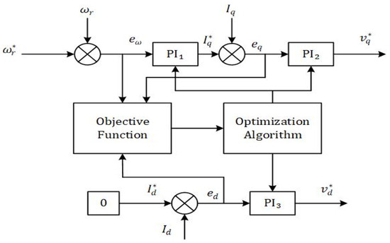
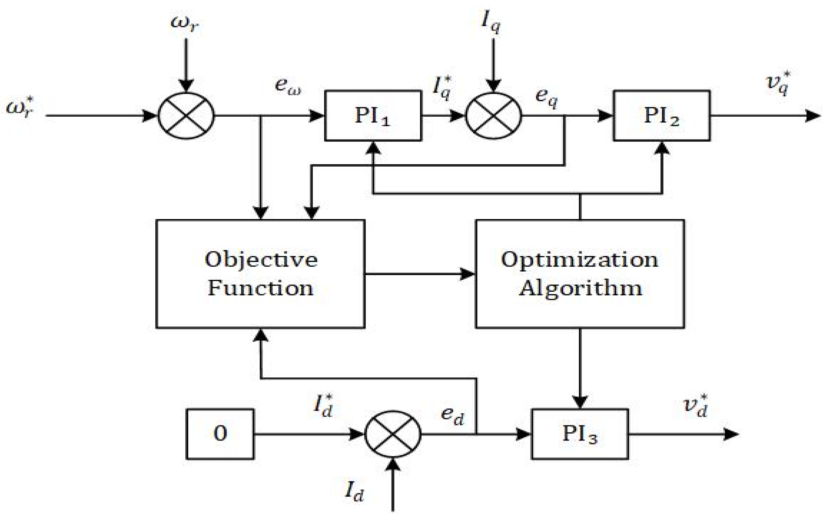
The optimization framework adopted in this work is illustrated in Figure 3. The objective function evaluates the speed, q-axis current, and d-axis current tracking errors, while the optimization algorithm iteratively updates the gains of the three PI controllers to minimize the overall ITAE-based performance index.
Figure 3.
Proposed ITAE-based optimization framework for simultaneous tuning of the speed-loop and current-loop PI controllers in the FOC PMSM drive.
4. Implementation of Optimization Algorithms
The ITAE-based PI controller tuning problem formulated in Section 3 is solved using five population-based metaheuristic optimization algorithms: Genetic Algorithm (GA), Particle Swarm Optimization (PSO), Gray Wolf Optimizer (GWO), Gazelle Optimization Algorithm (GOA), and White Shark Optimization (WSO). In all cases, each candidate solution represents a vector containing the proportional and integral gains of the three PI controllers employed in the FOC-based PMSM drive.
The optimization process is conducted offline using time-domain simulations of the PMSM model. To ensure a fair and unbiased comparison, all algorithms share the same decision variables, parameter bounds, normalized ITAE-based objective function, simulation conditions, population size, and termination criteria. The overall optimization procedure is illustrated by the corresponding flowcharts of each algorithm, while the following subsections highlight only the algorithm-specific update mechanisms.
4.1. Genetic Algorithm (GA)
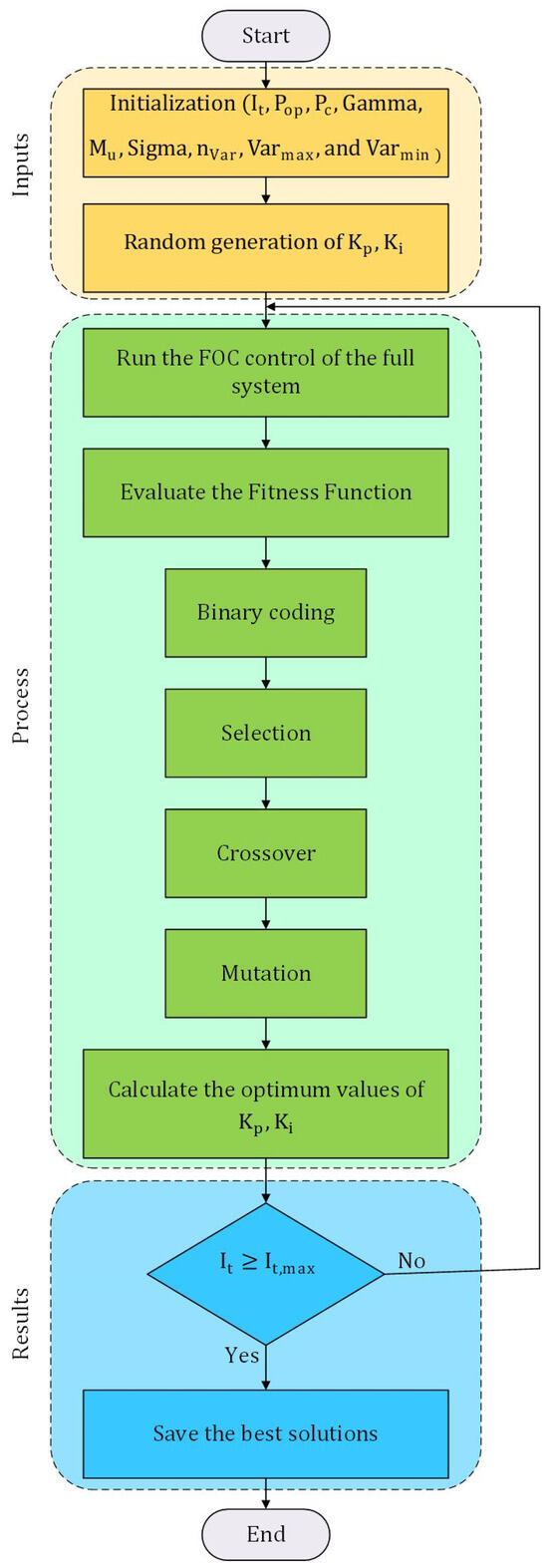
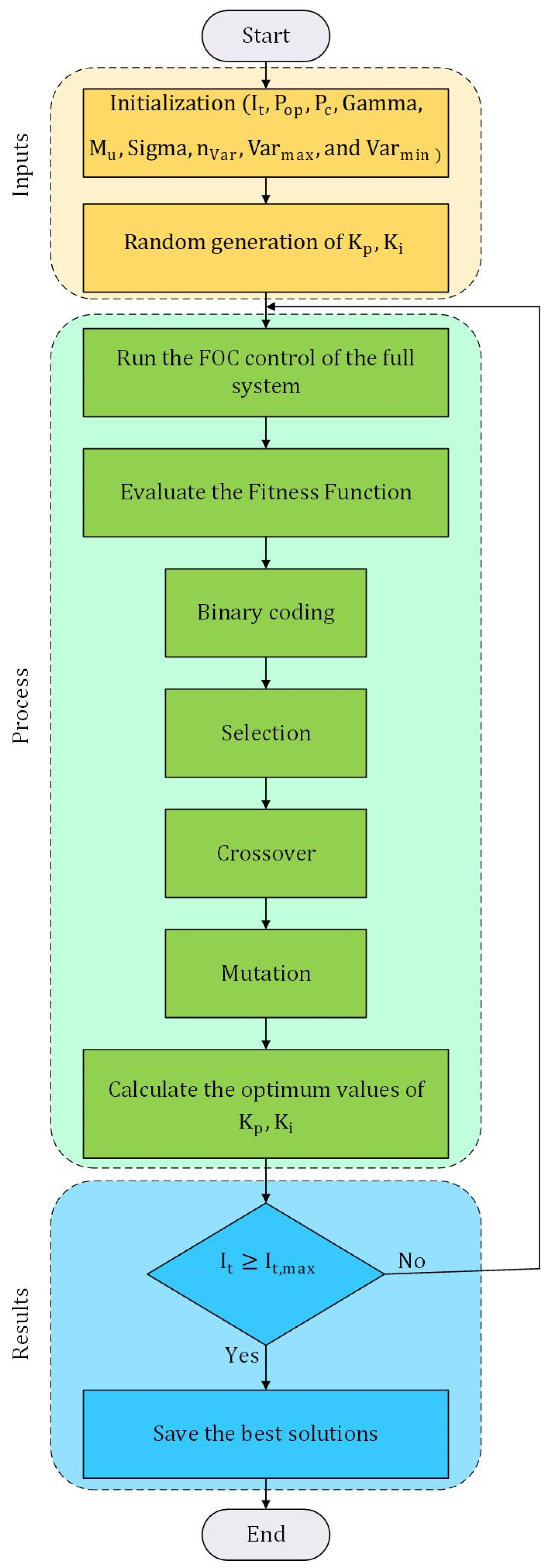
The Genetic Algorithm is an evolutionary optimization technique inspired by natural selection. In this work, each chromosome encodes a candidate set of PI controller gains [28]. The algorithm begins with a randomly generated population and iteratively evolves the solutions through selection, crossover, and mutation operations, as illustrated in the flowchart of Figure 4.
Figure 4.
GA flowchart.
The fitness of each chromosome is evaluated using the ITAE-based objective function. Selection favors individuals with lower fitness values, while crossover and mutation introduce diversity and prevent premature convergence, enabling effective exploration of the search space.
4.2. Particle Swarm Optimization (PSO)
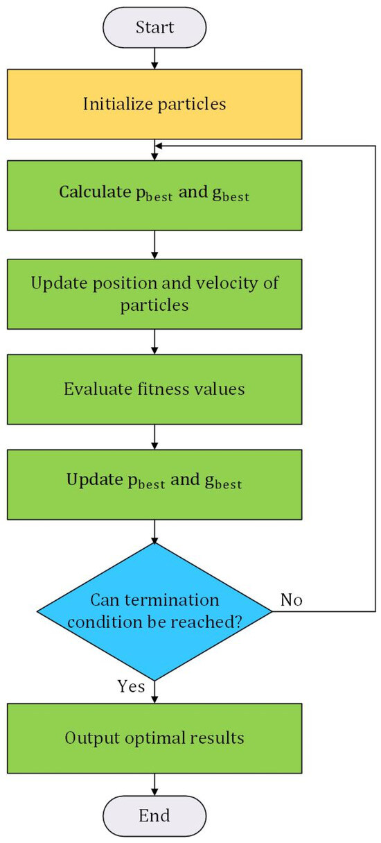
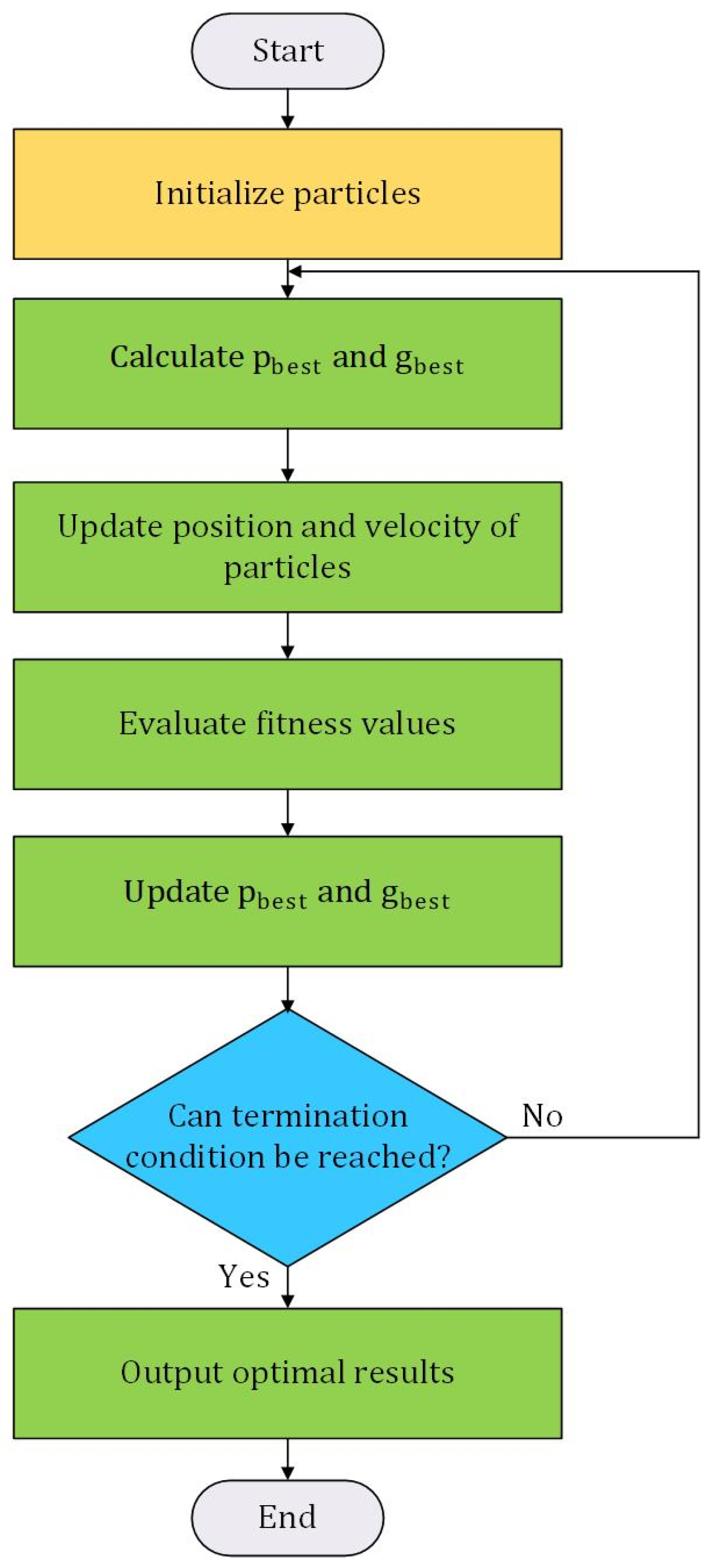
Particle Swarm Optimization is a swarm intelligence algorithm that simulates the social behavior of particles moving within a search space [29]. Each particle adjusts its position by considering its own best experience and the best solution found by the swarm, as presented in (17) and (18) and the flowchart shown in Figure 5.
Figure 5.
PSO flowchart.
The velocity and position updates are governed by:
where and denote the position and velocity of the -th particle at iteration , respectively; is the personal best position of the -th particle; is the global best position found by the swarm; is the inertia weight; and are the cognitive and social acceleration coefficients, respectively; and and are uniformly distributed random numbers in the interval .
4.3. Gray Wolf Optimizer (GWO)
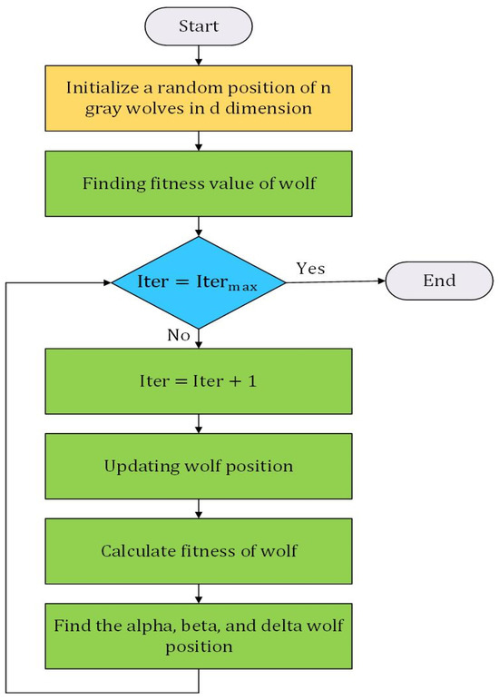
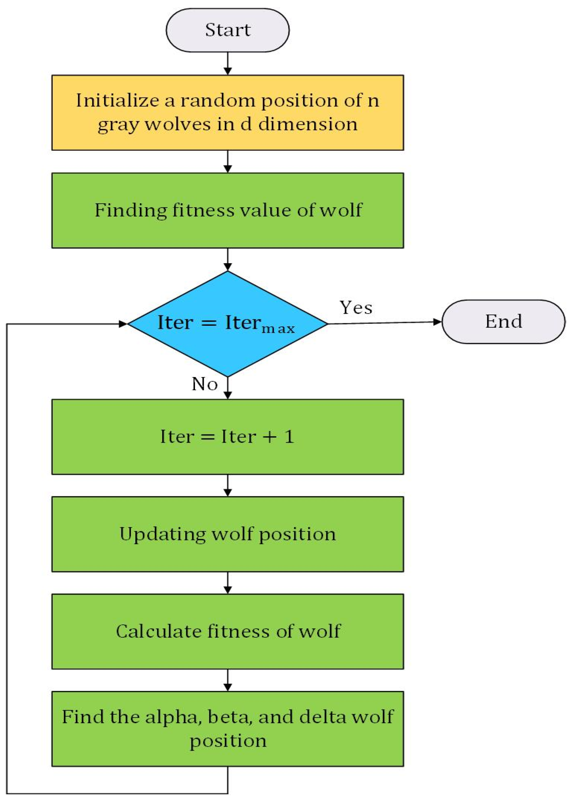
The Gray Wolf Optimizer is inspired by the leadership hierarchy and hunting strategy of gray wolves. The population is divided into four groups: alpha, beta, delta, and omega, where the alpha wolf represents the best candidate solution [19]. Position updates are guided by the three leading wolves, as depicted in Figure 6.
Figure 6.
GWO flowchart.
The position update mechanism is defined as:
where denotes the current wolf position, represents the position of the leading wolf (i.e., the best candidate solution), is the distance vector between the current wolf and the leader, and are coefficient vectors controlling the balance between exploration and exploitation during the optimization process.
4.4. Gazelle Optimization Algorithm (GOA)
4.4.1. Population Initialization
GOA starts with a random distribution of a population of gazelles in the search domain. This population includes a matrix X of size (n × d), with n being the number of gazelles (search agents) and d being the dimensionality of the optimization problem. The rows in the matrix represent the location of one gazelle in the search space. The first population matrix is represented as in Equation (24):
where denotes the population matrix of gazelles, is the population size (number of gazelles), is the dimensionality of the optimization problem, and each element represents the value of the -th decision variable of the -th gazelle.
Each element in the matrix is determined using the following equation:
where rand is a uniformly distributed random number in the interval , and denote the upper and lower bounds of the -th decision variable, respectively, while and denote the gazelle index and decision-variable index, respectively.
The best solution obtained during the initialization stage is designated as the top-ranked gazelle, around which an elite matrix of size (n × d) is constructed. This elite matrix serves as a directional reference for the remaining gazelles throughout subsequent iterations, enabling more efficient traversal of the search space.
4.4.2. Exploitation Phase
Within the GOA framework, both predators and gazelles are treated as search agents. Upon detecting a potential threat, the gazelles initiate a coordinated evasive response even before direct visual contact is established, as predators typically arrive after the gazelles have already begun to move.
An optimum solution candidate may be found during the optimization process and then substituted for the best-ranked gazelle in the matrix of the elite solution. This update process is repeated iteration after iteration, allowing for iterative improvement of the solution set. The mathematical equation that regulates this phase is shown in Equation (23) [30].
where is the updated position of the gazelle, is its current position, denotes the corresponding elite solution used as the search reference, is the grazing speed coefficient, is a uniformly distributed random number in the interval , and is a uniformly distributed random vector used to perturb the search direction during the exploitation phase.
In GOA, the predator–gazelle interaction constitutes the fundamental search mechanism that balances global exploration and local exploitation throughout the optimization process. Predator behavior enhances local exploitation around promising solutions, whereas the gazelles’ evasive movements promote global exploration. The interaction between these complementary behaviors enables the algorithm to maintain an effective balance between exploration and exploitation throughout the optimization process.
4.4.3. Exploration Phase
The exploration phase is activated as soon as the predator is detected. Gazelles respond to this threat by tail flicking, foot stamping, and jumping all four limbs up to 2 m high, all the time. This vertical jump is then normalized to a value between 0 and 1 in the GOA formulation to allow it to be mathematically included in the exploration mechanism. The numerical description of the gazelle’s response when the predators are detected is given as follows:
where denotes the maximum normalized grazing velocity of the gazelle during the exploration phase, represents the corresponding elite solution, and is a uniformly distributed random vector controlling the exploration direction.
The predator is modeled as pursuing the gazelle according to Equation (28), where the cumulative effect of the predator is represented by:
where is a random vector generated according to the Lévy distribution to introduce long-distance exploratory movements, thereby enhancing the global search capability during predator pursuit.
The probability of the gazelle escaping the predator is also factored into the algorithm by the term called the Predator Success Rate (PSR), which lowers the likelihood of premature convergence to a local optimum. The mathematical description of the predator–gazelle interaction is given in Equation (29).
where denotes the predator cumulative effect coefficient, which gradually decreases with the iteration number to balance exploration and exploitation; represents the Predator Success Rate threshold controlling the probability of switching between the two update strategies; and denote two randomly selected gazelle indices used to generate differential movements between candidate solutions; and is a binary decision vector whose elements are determined according to the uniformly distributed random number as follows:
The position of each gazelle is updated according to:
where denotes the best solution identified up to iteration , and are tunable weighting coefficients controlling the contributions of the exploitation and exploration terms, respectively, rand is a uniformly distributed random number in the interval , and Levy denotes the Lévy flight component that enhances the global exploration capability of the algorithm.
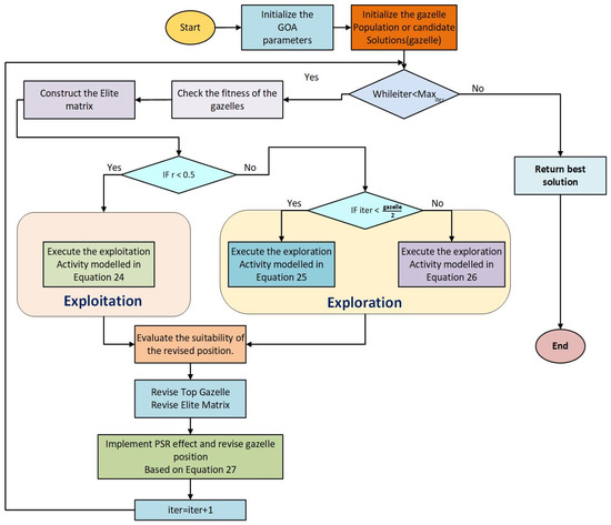
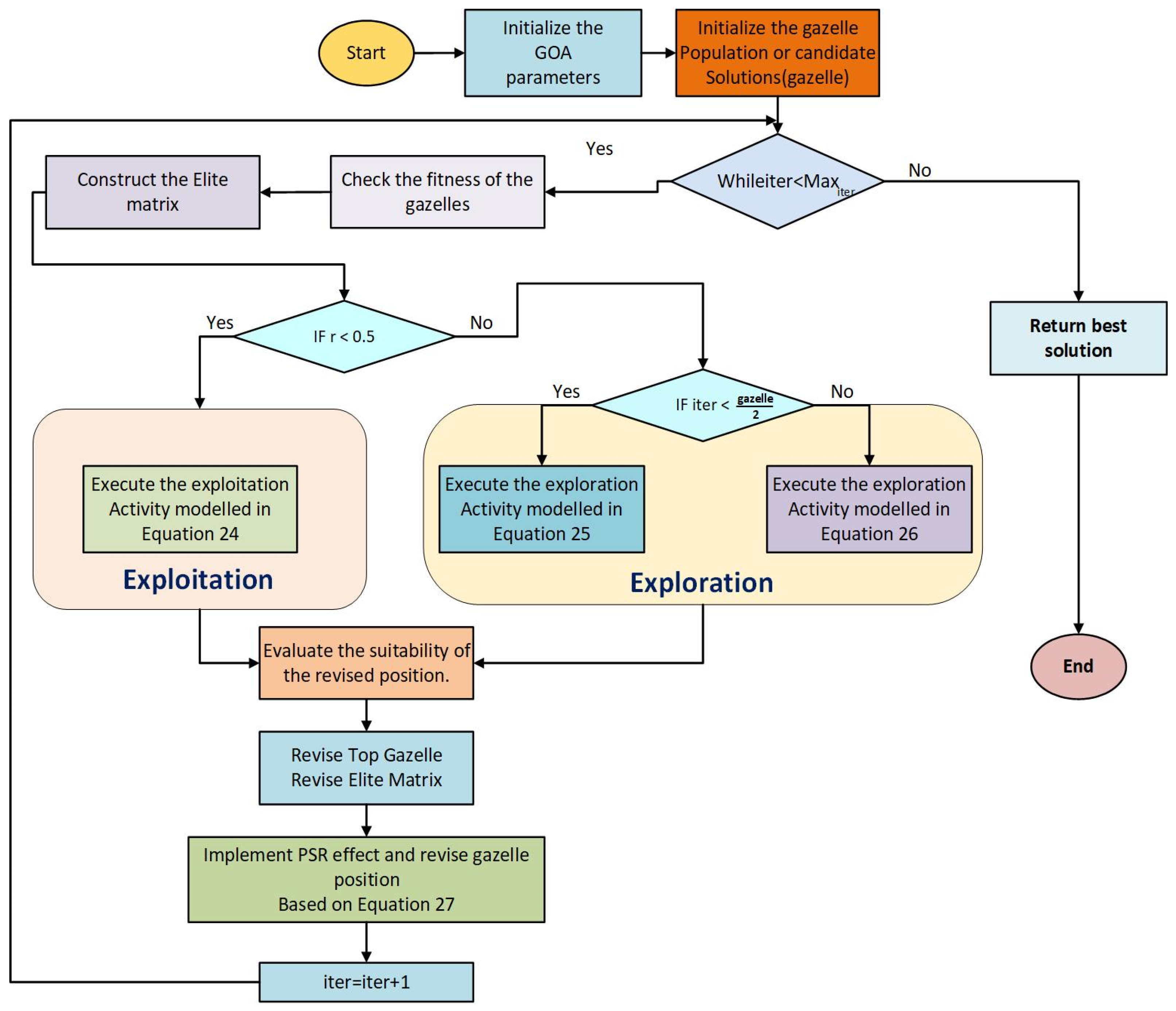
The flowchart of the GOA is illustrated in Figure 7 and consists of four successive steps, outlined as follows:
Figure 7.
GOA flowchart.
- Initialization: A population of gazelles is generated, with each individual encoding a set of (Kp, Ki) values randomly sampled within predefined bounds. The parameters governing the balance between exploration and exploitation are also established at this stage.
- Fitness Assessment: For each gazelle, the system is simulated, and a fitness measure (ITAE) is calculated to determine which of the currently available solutions is best.
- Position Updating: Two mechanisms are used for updating the positions of gazelles, exploration and exploitation:
- Exploration: where gazelles move away from the predators detected in their vicinity to a random safe region, which increases the diversity of the search.
- Exploitation: where gazelles incrementally adjust their position towards the better performer and the herd center by using smaller step sizes for refining the solutions.
- Boundary constraints are imposed, and the elite gazelle is preserved.
- Termination: The best Kp and Ki values are obtained in the final elite gazelle.
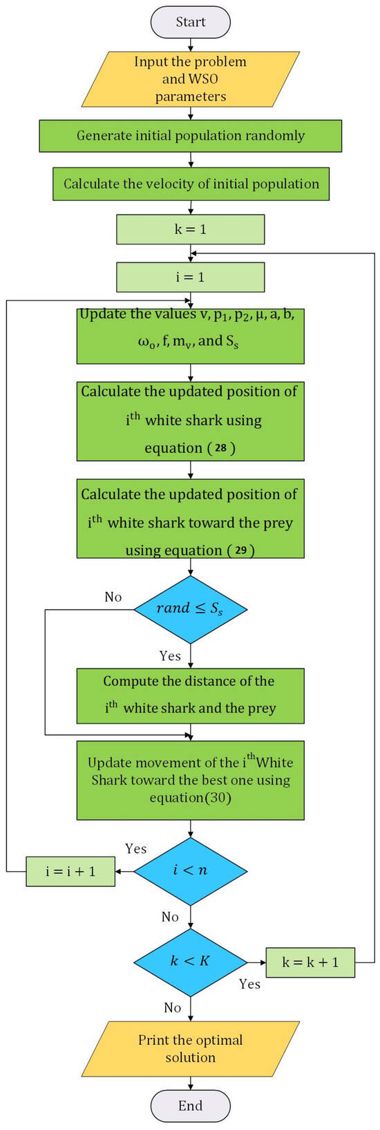
4.5. White Shark Optimization (WSO)
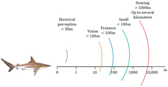
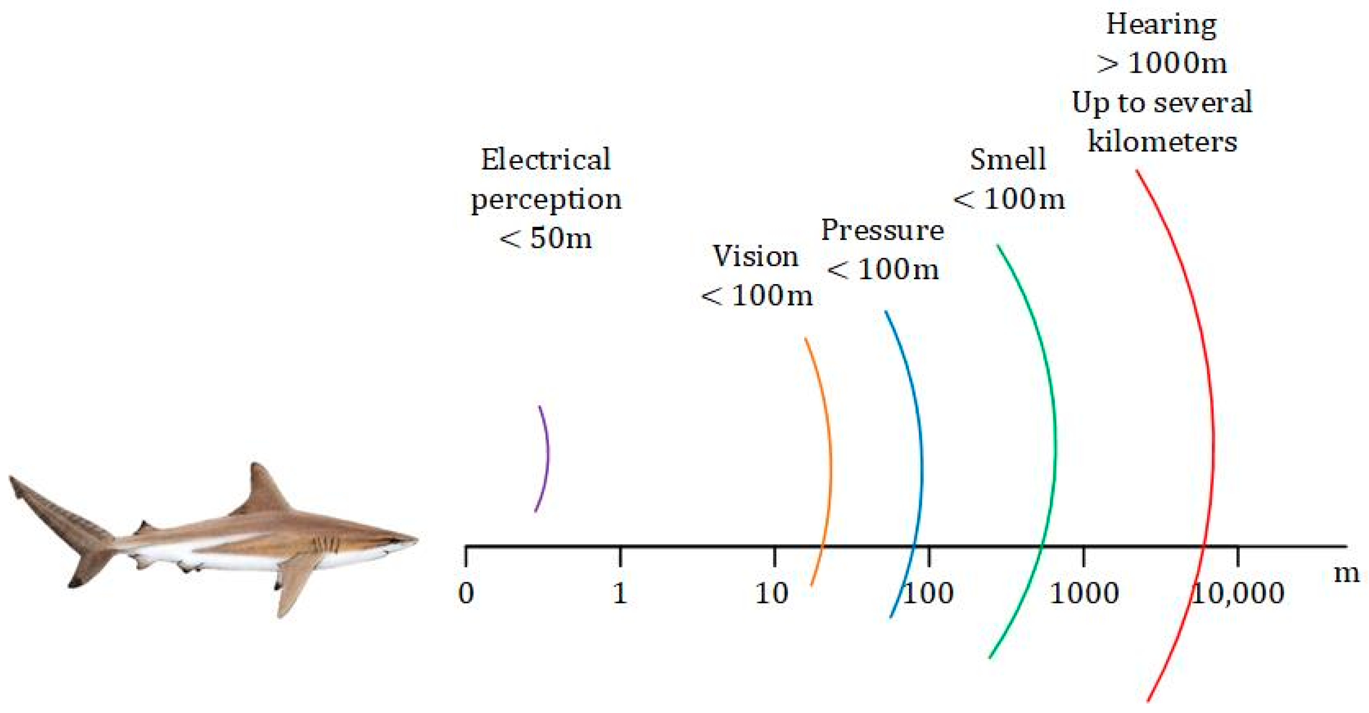
White Shark Optimization is a swarm-based metaheuristic inspired by the cooperative hunting behavior of white sharks. The biological inspiration behind the White Shark Optimization algorithm is derived from the exceptional hunting and sensing capabilities of white sharks [31]. As illustrated in Figure 8, white sharks utilize multiple sensing mechanisms, including electrical perception, vision, smell, pressure sensing, and hearing, to detect prey over different spatial ranges. This multi-sensory behavior motivates the balance between local exploitation and global exploration in the WSO search process, enabling efficient navigation toward optimal solutions in complex optimization problems [32].
Figure 8.
Sensory perception ranges of white sharks used as biological inspiration for the White Shark Optimization (WSO) algorithm.
The White Shark Optimization (WSO) algorithm is a population-based metaheuristic inspired by the hunting strategy and social behavior of great white sharks. The algorithm alternates between exploration and exploitation through velocity updating, position updating, movement toward the best shark, and fish-schooling behavior. The velocity of each white shark is updated according to:
where denotes the white shark index; is the updated velocity of the -th white shark at iteration ; is the global best solution obtained up to iteration ; is the personal best position of the -th white shark; and are uniformly distributed random numbers in ; and , , and are adaptive coefficients computed according to the original WSO formulation [32].
After updating the velocity, the position of each white shark is modified as follows:
where denotes the updated position of the -th white shark at iteration . The binary vectors, logical operators, oscillation frequency, movement force, and auxiliary variables used in the position update follow the original WSO formulation described in [32].
To improve the exploitation capability, each shark moves toward the best-performing shark in the population according to:
where is the updated position of the th white shark with respect to the location of the prey; provides either or to reverse the direction of the search; , , and are normally distributed numbers between ; the distance between the prey and white shark is illustrated by , as represented by (31); and demonstrates the efficacy of olfaction and vision in white sharks as they track other white sharks that are in proximity to ideal food.
where represents the distance between the prey and the white shark, and is a random number in the interval according to [32].
Finally, fish-schooling behavior is employed to update the position of each white shark and guide the population toward promising regions of the search space:
where denotes the updated position obtained through the fish-schooling strategy. The complete formulation of this mechanism is implemented according to the original WSO algorithm [32].
This mechanism enables the WSO algorithm to maintain a balance between global exploration and local exploitation, thereby enhancing convergence speed and solution quality. The WSO flowchart is shown in Figure 9.
Figure 9.
WSO flowchart.
The parameter settings adopted for the investigated optimization algorithms are summarized in Table 2. Unless otherwise stated, the parameters were selected according to the standard implementations of the corresponding optimization algorithms to ensure a consistent comparative evaluation.
Table 2.
Parameter settings of the optimization algorithms investigated.
The comparative evaluation presented in the following section serves two complementary purposes. First, it validates the effectiveness of the proposed multi-error ITAE optimization framework by applying different metaheuristic optimization algorithms under identical optimization settings and performance criteria. Second, it identifies the optimization algorithm that provides the most effective PI controller tuning for the investigated FOC-controlled PMSM drive. Therefore, the comparative results presented in the following section evaluate both the general applicability of the proposed optimization framework and the relative performance of the investigated optimization algorithms.
5. Results and Discussion
To validate the proposed multi-error ITAE optimization framework, comprehensive MATLAB/Simulink simulations were carried out on the FOC-controlled PMSM drive. Five metaheuristic optimization algorithms, namely Genetic Algorithm (GA), Particle Swarm Optimization (PSO), Gray Wolf Optimizer (GWO), Gazelle Optimization Algorithm (GOA), and White Shark Optimization (WSO), were employed to determine the optimal PI controller parameters. The motor parameters are illustrated in Table 3. Five simulation scenarios were considered to assess reference speed tracking capabilities, load disturbance rejection performance, and variable-speed operations representative of practical electric vehicle driving conditions.
Table 3.
Parameters of PMSM [33].
The PMSM parameters were adopted from the benchmark model reported in [33]. The referenced benchmark model does not explicitly specify rated operating conditions; therefore, controller optimization and the original comparative evaluation were performed using predefined reference-speed and load profiles. To further address the validation under rated operating conditions, an additional validation case was subsequently considered using the rated speed and load torque reported in [34], as described in Section 5.2. These rated operating values are used solely to define the additional validation condition and do not modify the PMSM parameters adopted from the benchmark model in [33].
5.1. Reference Speed Tracking Performance
The optimization process was carried out using a step reference speed of 150 rad/s under a constant load torque of 9.5 Nm. The PI controller gains were obtained by minimizing the proposed ITAE-based objective function under this operating condition. Subsequently, the optimized controller parameters were validated and comparatively evaluated under additional operating scenarios, including reference speed tracking, load disturbance rejection, and variable-speed operation, to assess their overall dynamic performance.
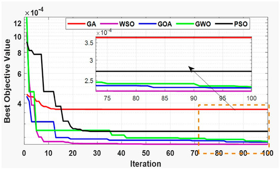
The convergence characteristics of the objective function for all optimization algorithms are presented in Figure 10. It can be observed that WSO achieved the lowest objective function value and demonstrated the fastest convergence among all investigated algorithms, indicating its superior optimization capability for the proposed ITAE-based objective function. The optimized PI controller gains obtained from each optimization algorithm are listed in Table 4, while the resulting dynamic performance indices are summarized in Table 5.
Figure 10.
Convergence characteristics of the ITAE-based objective function for different optimization algorithms.
Table 4.
Optimal PI gain values generated by different metaheuristic optimization algorithms.
Table 5.
Comparative dynamic performance of the PMSM drive during reference speed tracking.
In addition to the convergence characteristics, the computational runtime of each optimization algorithm was also recorded. As summarized in Table 5, all investigated algorithms required comparable execution times because they were implemented using the same high-fidelity MATLAB/Simulink model, objective function, population size, and maximum number of iterations. The observed runtime differences were therefore relatively small and mainly attributed to the inherent search behavior of each optimization algorithm.
The dynamic performance indices were calculated offline from the exported Simulink responses using a dedicated MATLAB 2022b (9.13.2049777) post-processing script. The rise time was defined as the time required for the speed response to increase from 10% to 90% of the reference value, while the settling time was determined using a ±2% settling band. The overshoot was computed from the maximum speed deviation relative to the reference value.
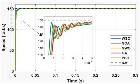
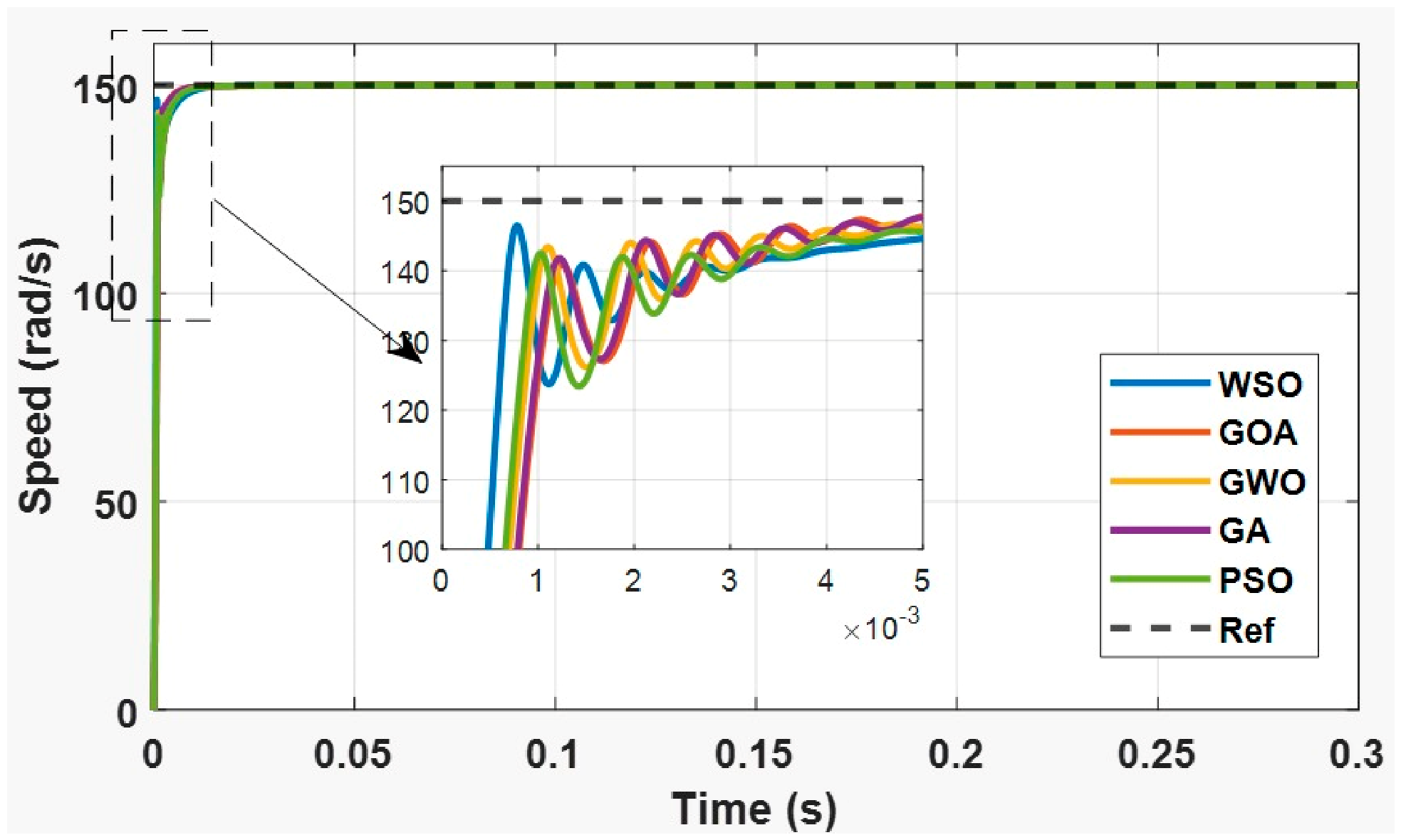
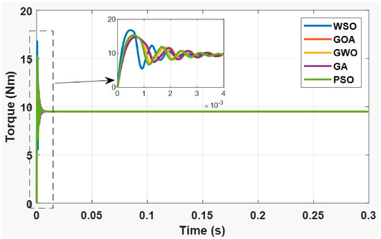
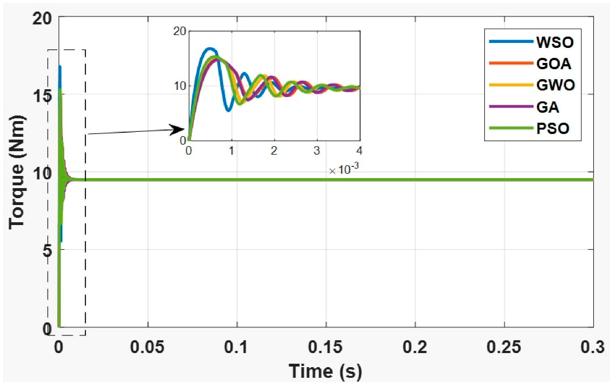
The corresponding speed and electromagnetic torque responses are illustrated in Figure 11 and Figure 12, respectively.
Figure 11.
Rotor speed tracking responses under step reference input.
Figure 12.
Electromagnetic torque responses during reference speed tracking.
Table 5 demonstrates the effectiveness of the proposed multi-error ITAE optimization framework in improving the reference speed tracking performance under identical optimization settings. All optimized controllers successfully tracked the reference speed with zero overshoot and negligible steady-state error, confirming the effectiveness of the proposed framework, regardless of the selected optimization algorithm. However, noticeable differences were observed in the transient and tracking performance. Among the investigated optimization algorithms, WSO achieved the best overall tracking performance, yielding the lowest RMSE (4.83887 rad/s), minimum ITAE (2.2697 × 10⁻⁴), and shortest optimization runtime (11,605.47 s). These results correspond to RMSE reductions of 18.39%, 13.43%, 17.98%, and 11.51% relative to the GOA, GWO, GA, and PSO, respectively. Likewise, the ITAE was reduced by 2.96%, 3.70%, 38.09%, and 16.30%, respectively. Although the GA and GOA exhibited slightly shorter settling times (0.00482 s and 0.00485 s, respectively), WSO provided the fastest rise time (0.00052 s) while maintaining excellent tracking accuracy and stable dynamic performance. These findings demonstrate that the proposed multi-error ITAE optimization framework provides accurate and reliable reference speed tracking, with White Shark Optimization representing the most effective optimization algorithm among the investigated methods for implementing the proposed framework under nominal operating conditions.
5.2. Load Disturbance Rejection Performance
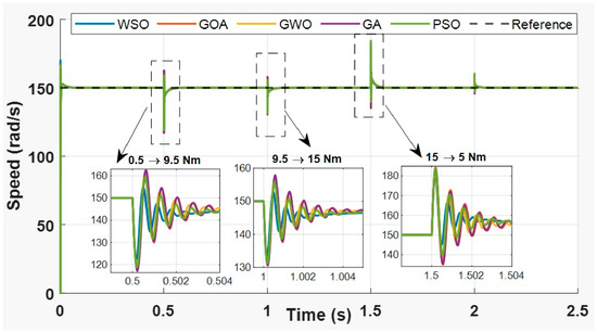
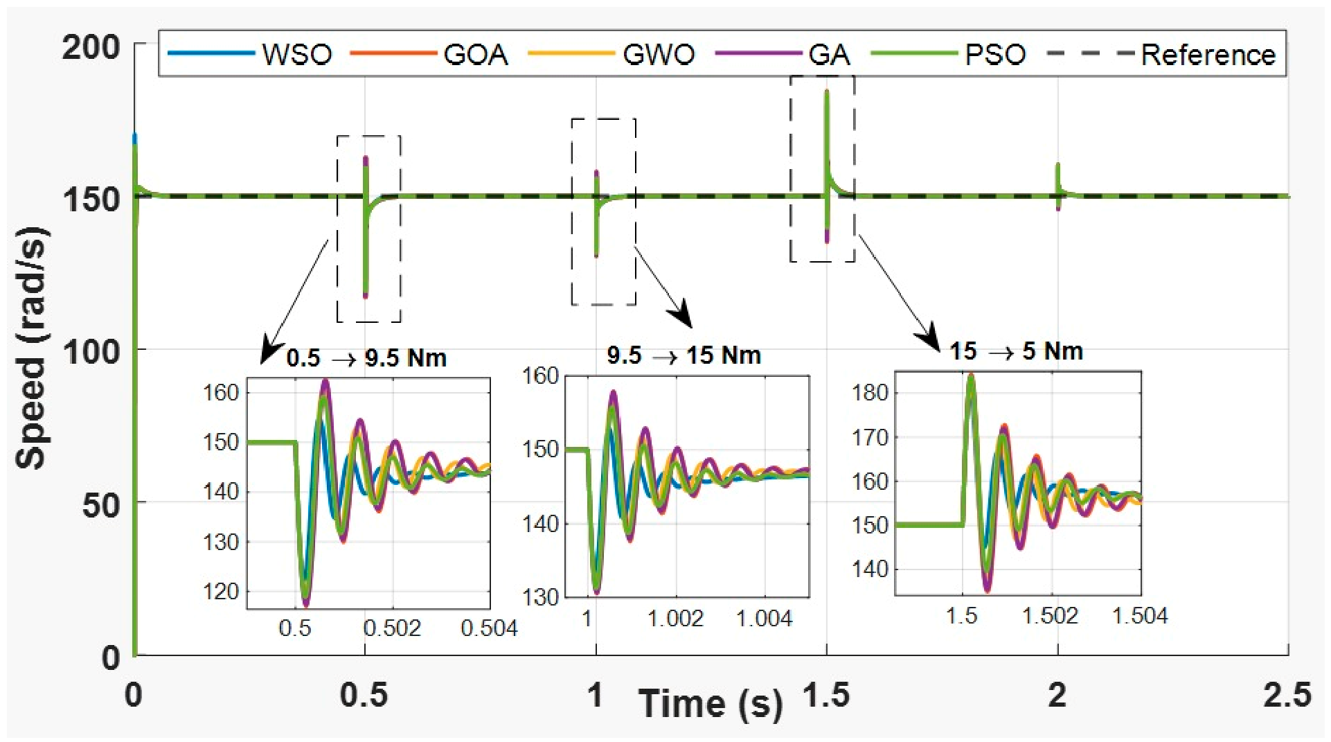
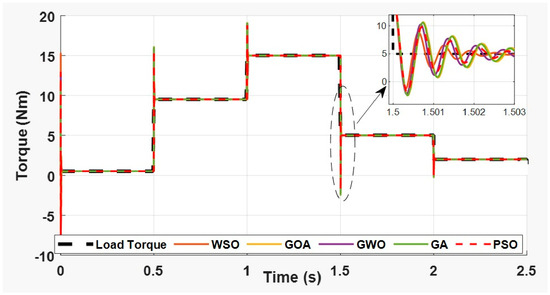
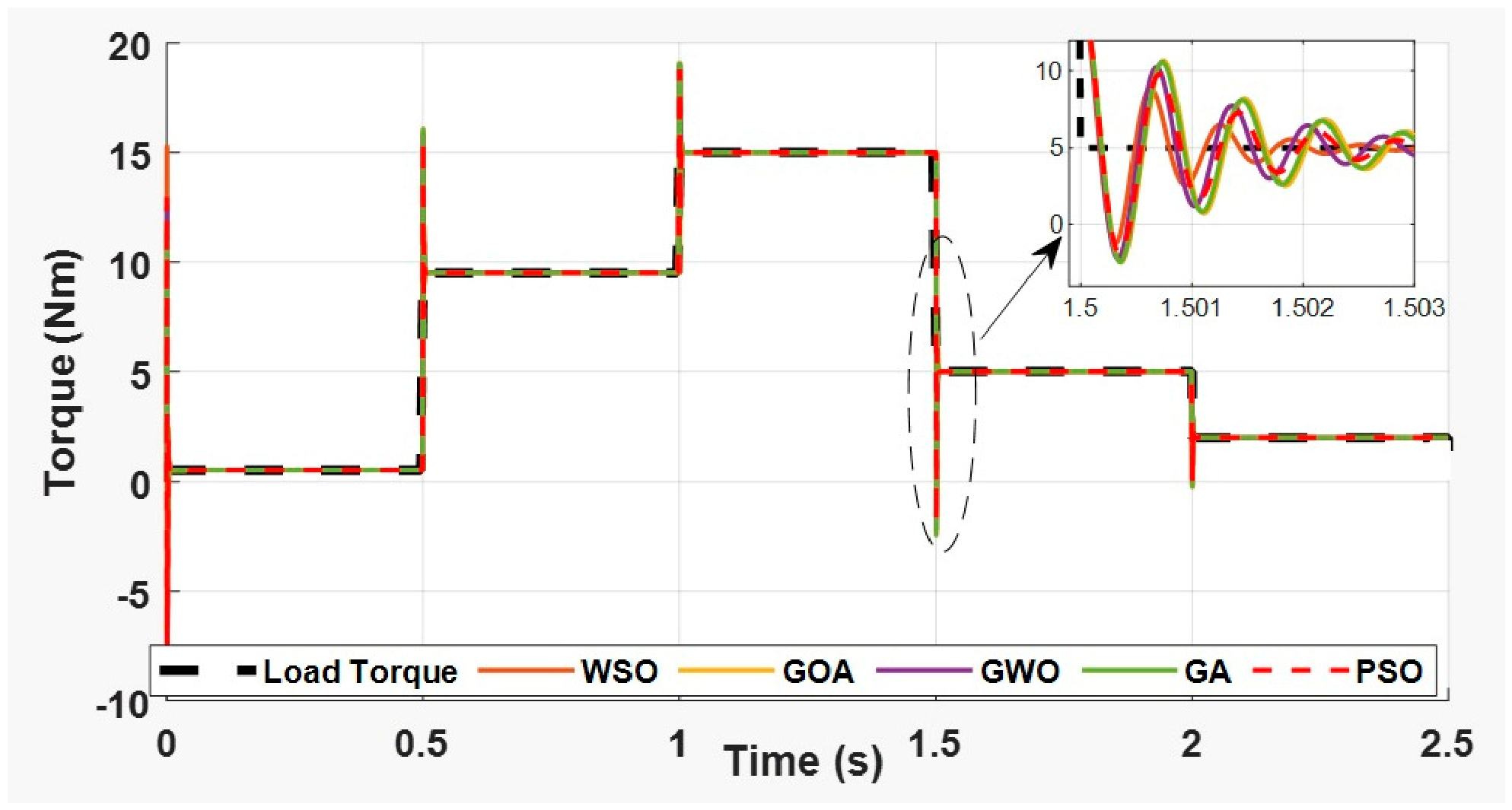
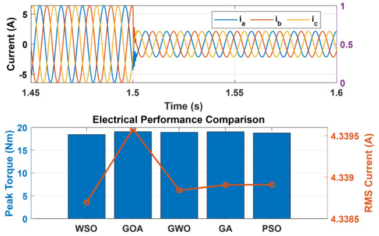
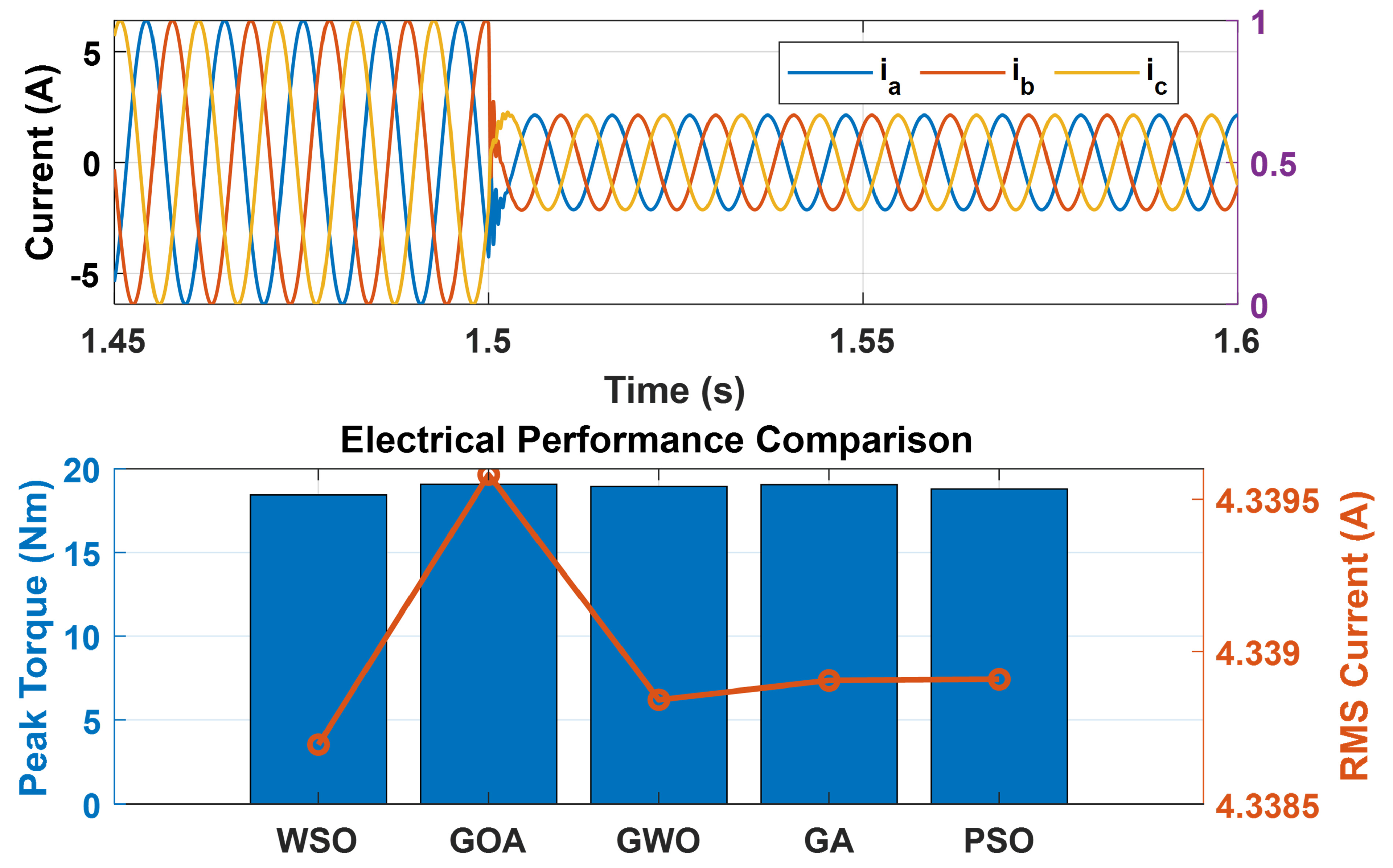
The disturbance rejection capability of the optimized controllers was investigated using successive load torque variations applied during operation. Specifically, the load torque was sequentially varied from 0.5 Nm to 9.5 Nm, then increased to 15 Nm, and finally reduced to 5 Nm to evaluate the controllers’ ability to reject external load disturbances under different loading conditions. Figure 13 presents the rotor speed responses, while Figure 14 illustrates the relationship between the applied load torque and the developed electromagnetic torque. Figure 15 shows the corresponding three-phase stator current responses.
Figure 13.
Rotor speed responses under successive load torque disturbances.
Figure 14.
Three-phase stator current responses during load disturbance rejection.
Figure 15.
Comparison of peak torque and rms current under load disturbance conditions.
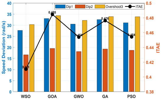
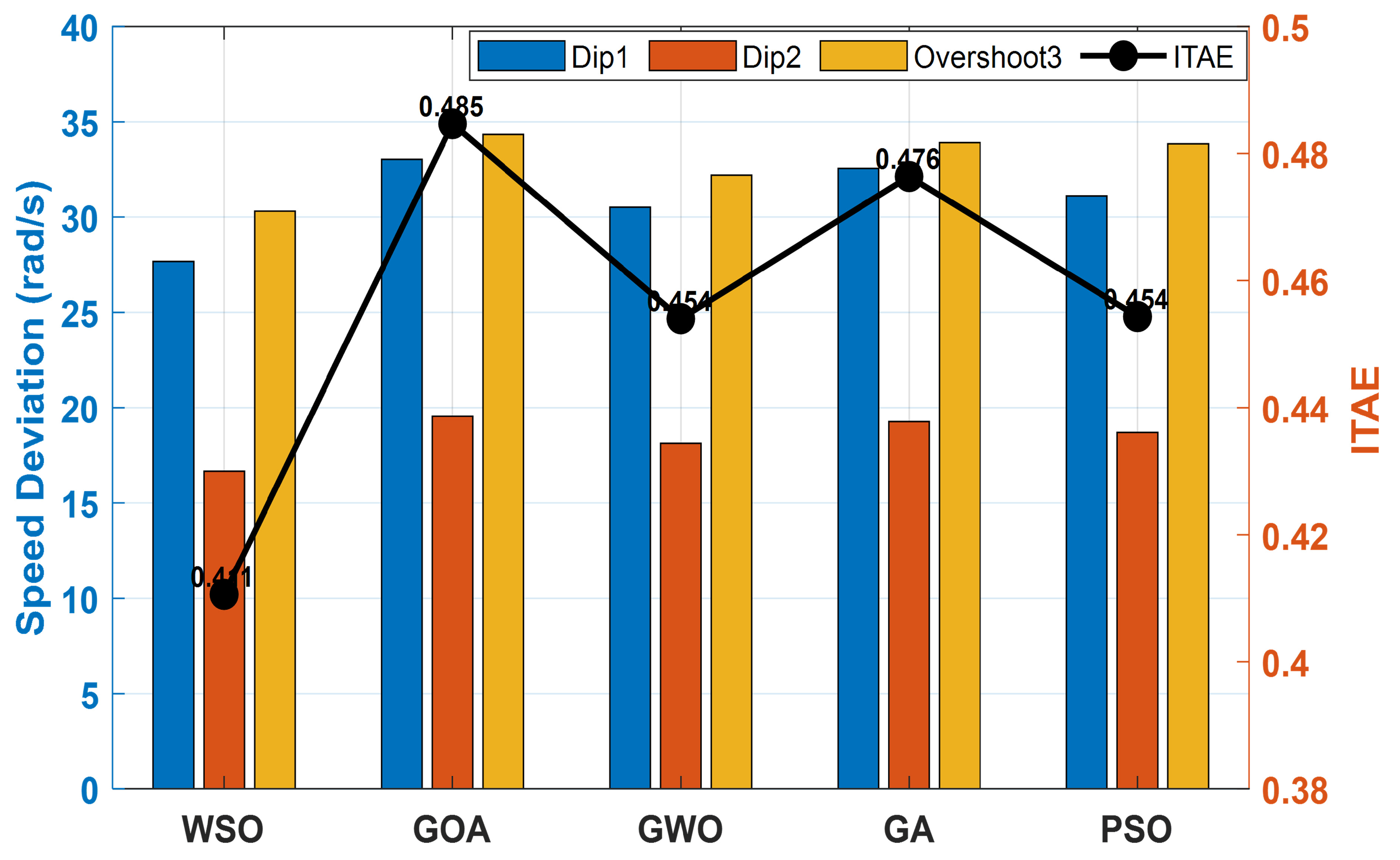
Table 6 summarizes the disturbance rejection performance of the investigated controllers. Speed Dip 1 and Speed Dip 2 denote the maximum speed reductions following the first and second load disturbances, respectively. Speed Overshoot represents the maximum positive speed deviation after the third disturbance, while Recovery Time 1–3 denote the corresponding recovery times required for the speed response to re-enter and remain within the ±2% settling band (the electrical performance indicators are provided in Table 7). A comparative visualization of the disturbance rejection indices is presented in Figure 16.
Table 6.
Load disturbance rejection performance metrics.
Table 7.
Electrical performance metrics under load disturbance conditions.
Figure 16.
Quantitative comparison of load disturbance rejection performance.
Table 6 and Table 7 further demonstrate the effectiveness of the proposed multi-error ITAE optimization framework under load disturbance conditions. All optimized controllers maintained stable operation and successfully recovered from the applied load disturbances, confirming the robustness of the proposed framework under identical optimization settings. Among the optimization algorithms investigated, WSO achieved the best overall disturbance rejection performance, recording the lowest ITAE of 0.4106, corresponding to reductions of 15.28%, 9.56%, 13.81%, and 9.62% compared with the GOA, GWO, GA, and PSO, respectively. Furthermore, WSO produced the lowest peak current of 9.63 A, representing reductions of 3.41%, 2.71%, 3.28%, and 1.93%, respectively, together with the lowest peak electromagnetic torque, torque RMS, and RMS current, indicating reduced electrical stress on the PMSM drive. These results demonstrate that the proposed multi-error ITAE optimization effectively enhances disturbance rejection while minimizing electrical stress, with White Shark Optimization providing the most effective implementation among the optimization algorithms investigated.
5.3. Variable-Speed Tracking Performance
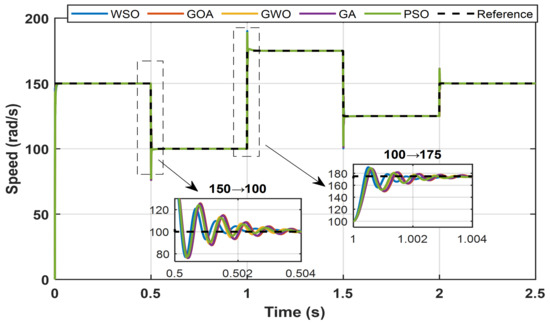
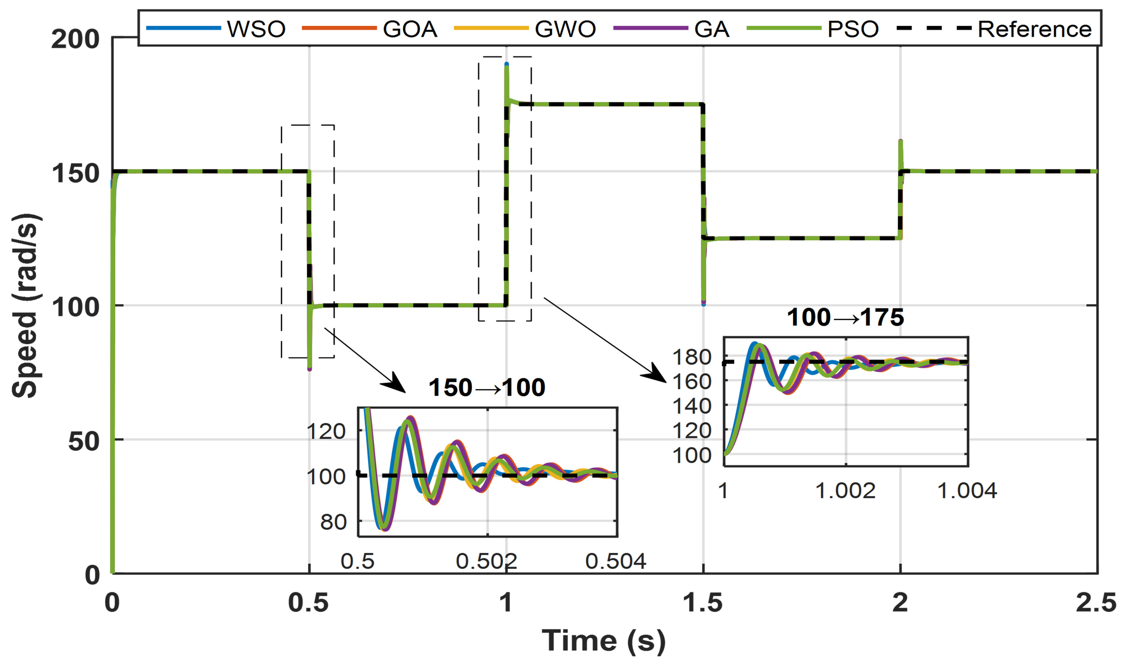
To emulate realistic electric vehicle operating conditions, the PMSM drive was evaluated under multiple speed transitions while maintaining a constant load torque of 9.5 Nm. The reference speed profile consisted of four successive operating points, namely 150→100 rad/s, 100→175 rad/s, 175→125 rad/s, and 125→150 rad/s. The resulting speed responses are shown in Figure 17, while the corresponding performance metrics are summarized in Table 8.
Figure 17.
Rotor speed responses under multiple variable-speed reference transitions.
Table 8.
Performance comparison of optimization algorithms under variable-speed tracking conditions.
Table 8 confirms the effectiveness of the proposed multi-error ITAE optimization framework under variable-speed operating conditions. When implemented using different optimization algorithms under identical optimization settings, the proposed framework consistently provided accurate and stable controller performance. Among the investigated optimization algorithms, WSO achieved the lowest RMSE (0.96 rad/s), ITAE (0.1716), and ISE (2.2573), corresponding to RMSE reductions of 15.82%, 10.97%, 14.07%, and 9.08% relative to the GOA, GWO, GA, and PSO, respectively. Similarly, the ITAE was reduced by 23.55%, 14.03%, 21.76%, and 12.99%, respectively. Furthermore, WSO maintained a comparable RMS current while achieving the best overall performance ranking, confirming that the proposed optimization framework provides superior variable-speed tracking, with White Shark Optimization representing the most effective optimization algorithm for implementing the proposed framework.
No instability was observed in any of the controllers in response to the different reference commands. However, there were some significant variations in the quality of tracking between the algorithms. As highlighted through these results, the performance of WSO, under variable-speed operating conditions, is the most favorable one with respect to the other considered techniques in terms of tracking accuracy, dynamic response, and control effort.
5.4. Validation at the Rated Operating Point
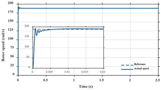
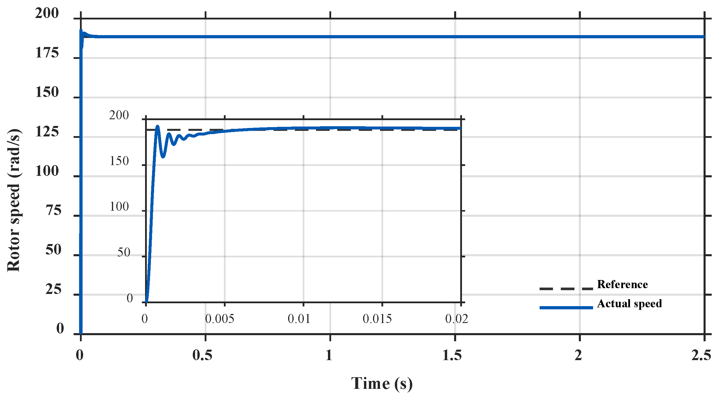
To further assess the performance of the optimized controller under rated operating conditions, an additional validation case was conducted at a reference speed of rad/s (1800 rpm) and a load torque of 4 Nm. The WSO-based PI controller gains obtained during the optimization process at a reference speed of 150 rad/s and a constant load torque of 9.5 Nm were retained without any retuning. Therefore, this test evaluates the ability of the optimized controller to maintain satisfactory speed regulation under an operating condition different from that used during the optimization process. The corresponding rotor-speed response is presented in Figure 18, while the resulting dynamic performance indices are summarized in Table 9. As shown in Figure 18, the actual rotor speed rapidly converges to the reference value of 188.5 rad/s and remains closely regulated around the desired operating point throughout the simulation. As reported in Table 9, the controller achieves a rise time of 0.00044 s and a settling time of 0.00386 s, with an overshoot of 2.0755%. The steady-state error is practically negligible at rad/s, while the RMSE and ITAE are 1.98615 rad/s and, respectively. The peak electromagnetic torque reaches 14.8351 Nm during the transient response. These results demonstrate that the optimized WSO controller maintains stable and accurate speed regulation at the rated validation operating point without requiring controller retuning.
Figure 18.
Rotor speed response of the WSO-based PMSM drive at the rated point.
Table 9.
Dynamic performance of the WSO-based PMSM drive at the rated operating point.
5.5. Validation Under WLTC Class 3 Driving Cycle
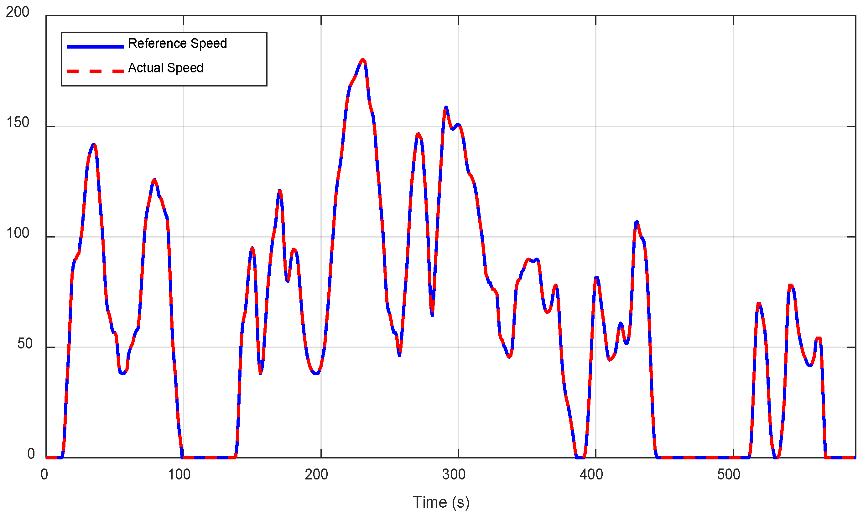
To further demonstrate the applicability of the proposed multi-error ITAE optimization framework to electric vehicle propulsion systems, an additional validation was conducted using the standardized WLTC Class 3 (Low phase) driving cycle [35]. Since the developed model represents the PMSM drive rather than the complete vehicle longitudinal dynamics, the WLTC speed profile was normalized and scaled to the maximum reference speed of 180 rad/s while preserving its original temporal characteristics. This validation complements the previously presented step-response, load disturbance, and variable-speed investigations by assessing the controller under a representative electric vehicle driving cycle.
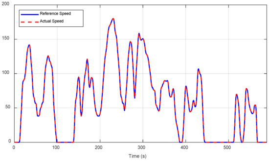
Figure 19 illustrates the reference and actual motor speed profiles under the WLTC Class 3 driving cycle. The WSO-tuned PI controller accurately tracks the continuously varying reference throughout the entire 589 s driving cycle with negligible tracking deviation, demonstrating excellent dynamic performance under representative electric vehicle operating conditions.
Figure 19.
Speed tracking performance under the WLTC Class 3 driving cycle.
The quantitative performance indices are summarized in Table 10. The proposed controller achieved an RMSE of 0.0340 rad/s and an ITAE of 0.1296, indicating highly accurate speed tracking throughout the complete driving cycle. The close agreement between the reference and actual speed trajectories, together with the low accumulated tracking error, further confirms the effectiveness of the proposed multi-error ITAE optimization framework for electric vehicle drive applications under realistic operating conditions.
Table 10.
Performance metrics under the WLTC Class 3 driving cycle.
5.6. Robustness Analysis Under Parameter Uncertainties
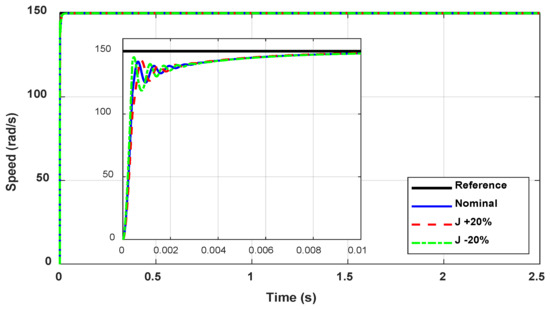
To further assess whether the optimized WSO-based PI controller remains stable and effective beyond the nominal conditions used during the optimization process, a parameter sensitivity analysis was conducted by introducing ±20% variations in stator resistance (Rs) and rotor inertia (J), while maintaining the optimized controller parameters unchanged and without any retuning. These parameter variations represent possible modeling uncertainties, parameter deviations due to manufacturing tolerances, and changes caused by thermal or mechanical operating conditions. The objective of this analysis is to evaluate whether the resulting closed-loop system can preserve stable operation and accurate speed tracking when the PMSM parameters deviate significantly from their nominal values used during the optimization process.
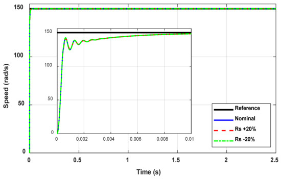
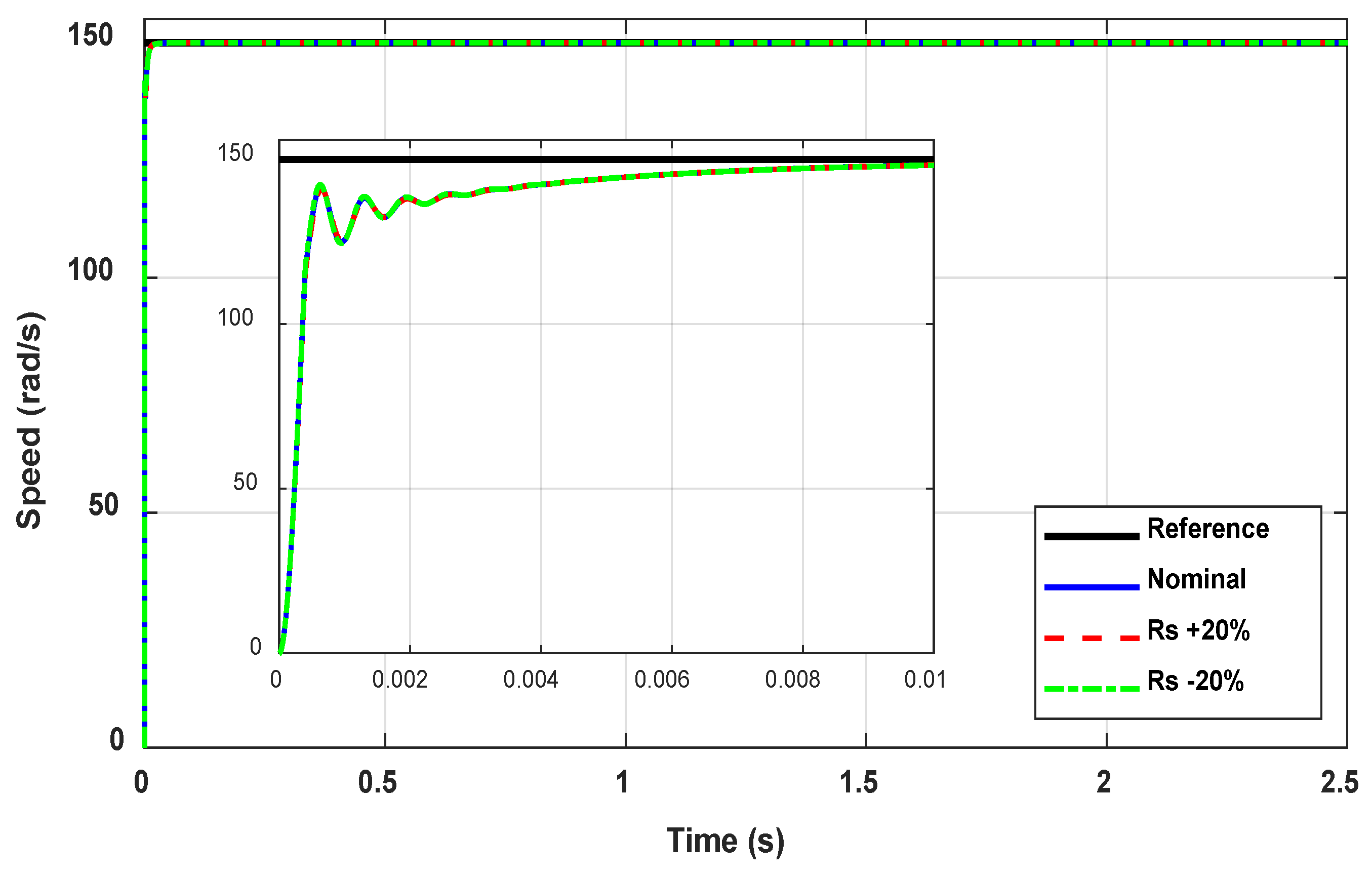
Figure 20 illustrates the speed responses obtained under ±20% variations in stator resistance. It can be observed that the proposed controller preserves excellent tracking performance for all investigated cases. The three speed responses almost overlap throughout the entire operating interval, while the zoomed view confirms only negligible differences during the initial transient period. The corresponding quantitative performance indices are summarized in Table 11. The maximum variation in RMSE is only 0.22%, whereas the settling time remains approximately constant around 7.55 ms. These results indicate that the proposed controller exhibits very low sensitivity to electrical parameter variations, confirming its robustness against stator resistance uncertainties.
Figure 20.
Robustness analysis of the proposed controller under ±20% stator resistance () variations.
Table 11.
Performance metrics under stator resistance variations.
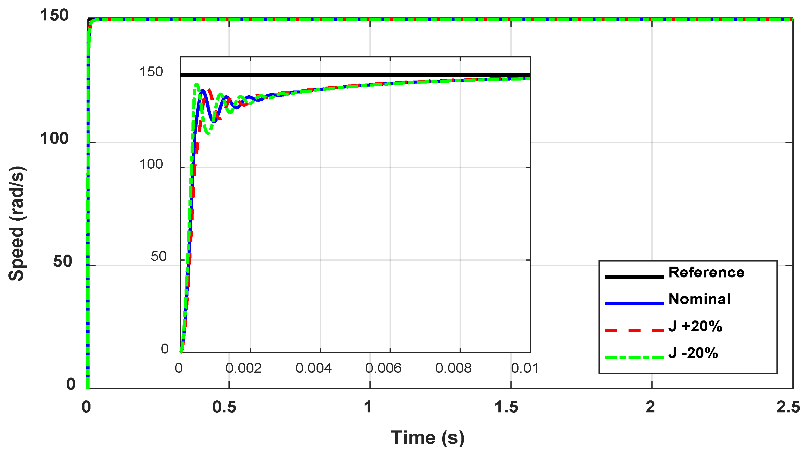
Figure 21 presents the robustness evaluation under ±20% variations in the rotor inertia. As expected, changes in the mechanical inertia produce slightly larger deviations than those observed for the stator resistance because the inertia directly influences the mechanical dynamics of the drive system. Nevertheless, all responses remain stable with fast convergence and accurate reference tracking. As summarized in Table 12, the maximum variation in RMSE is below 5%, while the settling time changes only slightly, remaining within the range of 7.24–7.76 ms. These results demonstrate that the proposed controller maintains stable closed-loop operation and satisfactory dynamic performance, even under considerable mechanical parameter uncertainties, without requiring any modification of the optimized controller gains.
Figure 21.
Robustness analysis of the proposed controller under ±20% rotor inertia () variations.
Table 12.
Performance metrics under rotor inertia variations.
Overall, the robustness analysis confirms that the proposed WSO-based tuning approach provides a controller capable of maintaining stable and accurate speed regulation despite significant electrical and mechanical parameter variations. In conjunction with the additional rated-operating-point validation presented in Section 5.4, these results demonstrate that the optimized controller is not limited to the nominal optimization condition and remains effective when the operating condition and PMSM parameters deviate from those used during controller tuning. No retuning of the optimized gains was performed in these additional validation and robustness cases.
5.7. Performance Assessment
The comparative evaluation conducted across the three simulation scenarios demonstrates the effectiveness of the proposed multi-error ITAE optimization framework for simultaneous PI controller tuning in FOC-controlled PMSM drives. When implemented using different metaheuristic optimization algorithms under identical optimization settings, the proposed framework consistently achieved accurate reference tracking, effective load disturbance rejection, and satisfactory variable-speed operation, confirming its applicability for high-performance electric vehicle drive systems.
Among the investigated optimization algorithms, White Shark Optimization (WSO) provided the most effective implementation of the proposed framework, achieving the best overall performance in terms of tracking accuracy, disturbance rejection, and dynamic response. WSO consistently produced the lowest tracking errors and superior performance indices while maintaining reduced electrical stress on the PMSM drive. These results indicate that the proposed optimization framework is capable of improving overall controller performance, with WSO representing the most suitable optimization algorithm among the investigated methods for implementing the proposed framework.
6. Limitations and Future Research Directions
While the proposed optimization framework demonstrated promising performance under various operating conditions, several aspects remain open for further investigation to broaden the scope and practical applicability of the present study.
Although all optimization algorithms were evaluated using the same objective function, decision variables, search bounds, population size, and maximum number of iterations, each optimizer retained its original search and population initialization mechanisms according to its standard implementation. Consequently, the convergence curves may start with different initial objective function values. Future studies may adopt identical fitness evaluation budgets and common initial populations to further strengthen the fairness and consistency of algorithmic benchmarking.
The present comparative evaluation was conducted using a single optimization run for each investigated metaheuristic algorithm. Although all algorithms were evaluated under identical optimization settings, additional statistical validation based on multiple independent runs would further strengthen the reliability of the comparative assessment. Owing to the use of a high-fidelity MATLAB/Simulink model of the complete FOC-controlled PMSM drive, each optimization run requires repeated time-domain simulations of the entire drive system, resulting in a substantial computational burden. Consequently, comprehensive statistical analyses involving multiple independent runs and significance tests (e.g., Wilcoxon rank-sum or Friedman tests) were beyond the scope of the present study and are considered an important direction for future research.
Although the proposed controller demonstrated stable operation under comprehensive time-domain validation, including the WLTC driving cycle and robustness analysis, explicit frequency-domain stability analysis (e.g., Bode or Nyquist) was beyond the scope of this study and will be considered in future work.
Furthermore, the present study employs an average-value inverter model within a speed-controlled FOC architecture to evaluate the proposed optimization framework. Consequently, inverter switching dynamics are not represented, and switching-induced torque quality metrics, such as electromagnetic torque ripple, cannot be evaluated within the adopted simulation model. In addition, since the primary control objective is rotor speed regulation rather than direct torque tracking, torque RMS error is not considered an appropriate performance metric for the adopted control architecture. Future work will therefore extend the proposed framework to a detailed switching-inverter model to enable comprehensive torque quality assessment under practical operating conditions.
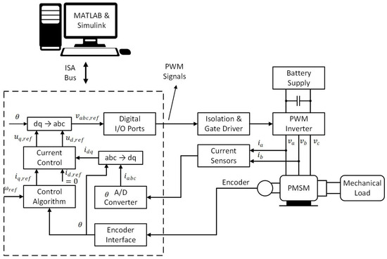
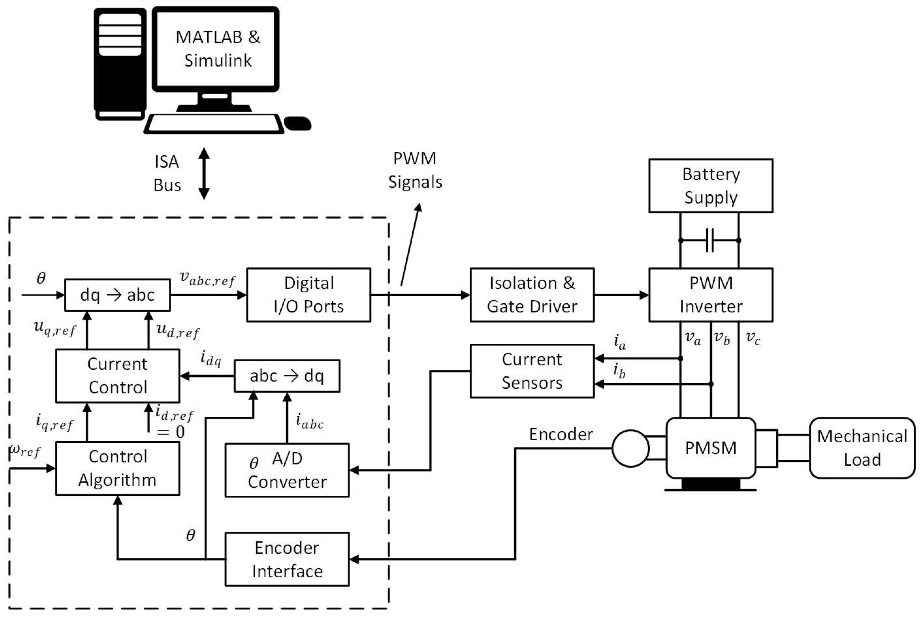
Although the proposed ITAE-based optimization framework demonstrated promising performance under comprehensive MATLAB/Simulink simulations, the present study has not yet been validated through real-time implementation. To clarify the practical implementation pathway of the proposed methodology, a basic DSP-based implementation scheme is presented in Figure 22. The optimized PI controller parameters, obtained offline through the MATLAB/Simulink-based optimization process, can be transferred to the DSP controller for real-time execution. As illustrated in Figure 22, the DSP receives the measured phase currents through the current-sensing and A/D interfaces, while the rotor position and speed are obtained through the encoder interface. The measured phase currents are transformed into the reference frame, and the control algorithm generates the required voltage references based on the speed and current control loops. The resulting control commands are then converted into PWM signals and applied through the gate-driver and inverter stages to the PMSM. WSO remains an offline stage, whereas the DSP is responsible for the real-time execution of the optimized control law.
Figure 22.
Basic DSP implementation scheme of the proposed WSO-tuned FOC PMSM drive.
Future work will focus on experimental verification using Hardware-in-the-Loop (HIL), DSP-based control platforms, and a laboratory PMSM testbench to further evaluate the practical applicability, robustness, and implementation feasibility of the proposed controller tuning strategy under realistic operating conditions. Such experimental validation would also enable the assessment of practical issues, including measurement noise, parameter uncertainties, computational delays, and hardware nonidealities, which cannot be fully captured by simulation alone.
7. Conclusions
This paper presented a multi-error ITAE-based optimization framework for simultaneous tuning of the speed and current PI controllers in a field-oriented control (FOC) PMSM drive intended for electric vehicle applications. Unlike conventional tuning approaches that optimize a single performance index, the proposed framework minimizes a composite objective function that simultaneously considers the rotor speed, q-axis current, and d-axis current tracking errors, thereby improving both dynamic response and control accuracy. To validate the proposed framework, five metaheuristic optimization algorithms (GA, PSO, GWO, GOA, and WSO) were employed under identical optimization settings and evaluated through three representative operating scenarios, namely reference-speed tracking, load disturbance rejection, and variable-speed operation. The simulation results demonstrated that the proposed optimization framework consistently produced stable and effective controller tuning, regardless of the selected optimizer, confirming its applicability for high-performance PMSM drive systems. Among the optimization algorithms investigated, White Shark Optimization (WSO) achieved the best overall performance. It produced the lowest tracking errors, superior disturbance rejection, reduced electrical stress, and the best dynamic response across the investigated operating conditions. In particular, WSO achieved the lowest RMSE of 0.96 rad/s during the variable-speed operating scenario, confirming its suitability as the most effective optimizer for the proposed optimization framework. Overall, the obtained results demonstrate that the proposed multi-error ITAE optimization framework provides an effective and systematic approach for PI controller tuning in FOC-controlled PMSM drives, while WSO represents the most suitable optimization algorithm among the investigated methods for implementing this framework. Future work will focus on real-time experimental validation using Hardware-in-the-Loop (HIL), DSP-based control platforms, and laboratory PMSM test benches to further investigate robustness, implementation feasibility, and practical performance under realistic operating conditions, including parameter uncertainties, measurement noise, and computational delays. This future direction is consistent with the limitations identified in the present study.
Author Contributions
Conceptualization, A.M., M.E., and R.A.E.-S.; Methodology, A.M., M.E., and R.A.E.-S.; Software, A.M.; Validation, A.M., M.E., and R.A.E.-S.; Formal analysis, M.E. and R.A.E.-S.; Investigation, A.M.; Resources, A.M., M.E., and R.A.E.-S.; Data curation, M.E. and R.A.E.-S.; Writing—original draft, A.M. and M.E.; Writing—review and editing, R.A.E.-S.; Visualization, A.M. and M.E.; Supervision, R.A.E.-S.; Project administration, R.A.E.-S.; Funding acquisition, R.A.E.-S. All authors have read and agreed to the published version of the manuscript.
Funding
This research received no external funding.
Data Availability Statement
The original contributions presented in this study are included in the article. Further inquiries can be directed to the corresponding authors.
Conflicts of Interest
The authors declare no conflicts of interest.
References
- Monadi, M.; Nabipour, M.; Akbari-Behbahani, F.; Pouresmaeil, E. Speed Control Techniques for Permanent Magnet Synchronous Motors in Electric Vehicle Applications Toward Sustainable Energy Mobility: A Review. IEEE Access 2024, 12, 119615–119632. [Google Scholar] [CrossRef] [Scilit]
- Ibrahim, M.; Järg, O.; Seppago, R.; Rassõlkin, A. Performance Optimization of a High-Speed Permanent Magnet Synchronous Motor Drive System for Formula Electric Vehicle Application. Sensors 2025, 25, 3156. [Google Scholar] [CrossRef] [Scilit] [PubMed]
- Alagmy, A.R.; Sarhan, M.M.; Matar, O.; Elagamy, Y.; Khattab, M.H.; Bekhit, M.M.; Mashaly, A.; Abdelkader, A.; Kaddah, S.S.; Badr, B.M. Design and Development of Drivetrain System for Electric Motorcycles. In Proceedings of the International Middle East Power System Conference, MEPCON; Institute of Electrical and Electronics Engineers Inc.: New York, NY, USA, 2024. [Google Scholar] [CrossRef] [Scilit]
- Özçiflikçi, O.E.; Koç, M.; Bahçeci, S.; Emiroğlu, S. Overview of PMSM control strategies in electric vehicles: A review. Int. J. Dyn. Control 2023, 12, 2093–2107. [Google Scholar] [CrossRef] [Scilit]
- Sivakumar, V.; Lakshmi, D.; Padmashini, R.K.; Vijayarajeswaran, R. A Technical Review of Controller Architectures, Modulation Schemes, Electric Motor Types, and Multiphase Drive Systems for Electric Vehicle Applications; Institute of Electrical and Electronics Engineers Inc.: New York, NY, USA, 2025; pp. 65–75. [Google Scholar] [CrossRef] [Scilit]
- Çelik, E.; Karayel, M. Effective speed control of brushless DC motor using cascade 1PDf-PI controller tuned by snake optimizer. Neural Comput. Appl. 2024, 36, 7439–7454. [Google Scholar] [CrossRef] [Scilit]
- Çelik, E.; Gör, H. Enhanced speed control of a DC servo system using PI + DF controller tuned by stochastic fractal search technique. J. Frankl. Inst. 2019, 356, 1333–1359. [Google Scholar] [CrossRef] [Scilit]
- Tepljakov, A.; Alagoz, B.B.; Yeroglu, C.; Gonzalez, E.A.; Hosseinnia, S.H.; Petlenkov, E.; Ates, A.; Cech, M. Towards Industrialization of FOPID Controllers: A Survey on Milestones of Fractional-Order Control and Pathways for Future Developments. IEEE Access 2021, 9, 21016–21042. [Google Scholar] [CrossRef] [Scilit]
- Sreeram, K.; Preetha, P.K.; Rodríguez-García, J.; Álvarez-Bel, C. A Comprehensive Review of Torque and Speed Control Strategies for Switched Reluctance Motor Drives. CES Trans. Electr. Mach. Syst. 2025, 9, 46–75. [Google Scholar] [CrossRef] [Scilit]
- Lipu, M.S.H.; Faisal, M.; Ansari, S.; Hannan, M.A.; Karim, T.F.; Ayob, A.; Hussain, A.; Miah, S.; Saad, M.H.M. Review of Electric Vehicle Converter Configurations, Control Schemes and Optimizations: Challenges and Suggestions. Electronics 2021, 10, 477. [Google Scholar] [CrossRef] [Scilit]
- Huang, Y.; Zhao, M.; Zhang, J.; Lu, M. The Hall Sensors Fault-Tolerant for PMSM Based on Switching Sensorless Control with PI Parameters Optimization. IEEE Access 2022, 10, 114048–114059. [Google Scholar] [CrossRef] [Scilit]
- Kethiri, M.F.; Charrouf, O.; Betka, A.; Tibermacine, I.E.; Napoli, C. Hybrid fuzzy-PSO based self-tuning fractional order PI controller for BLDC motors in electric vehicles: Comparative analysis and experimental validation. J. Vib. Control 2025, 32, 5383–5404. [Google Scholar] [CrossRef] [Scilit]
- Ben Regaya, C.; Farhani, F.; Zaafouri, A.; Chaari, A. Adaptive proportional-integral fuzzy logic controller of electric motor drive. Eng. Rev. 2021, 41, 26–40. [Google Scholar] [CrossRef] [Scilit]
- Çelik, E.; Izci, D.; Ekinci, S.; Bekiroğlu, E.; Oliva, D.; Abdel-Salam, M.; Tejani, G.G.; Mousavirad, S.J. Nonlinear Controller Design and its Optimization for Real-Time Implementation for a Servo Motor Drive. IET Control Theory Appl. 2026, 20, e70140. [Google Scholar] [CrossRef] [Scilit]
- Sankar, A.; Vijayabhanu, R. Enhancing Methane Production in Anaerobic Digestion using Hybrid Machine Learning and Bio-Inspired Algorithms: A Comprehensive Review. In Proceedings of the 5th International Conference on Soft Computing for Security Applications, ICSCSA 2025; Institute of Electrical and Electronics Engineers Inc.: New York, NY, USA, 2025; pp. 1361–1366. [Google Scholar] [CrossRef] [Scilit]
- Bazi, S.; Benzid, R.; Said, N. Soft Computing Using an HPSOGWO variant for Functions Optimization and PMSM Drive Control. In 2024 12th International Conference on Systems and Control, ICSC 2024; Institute of Electrical and Electronics Engineers Inc.: New York, NY, USA, 2024; pp. 360–366. [Google Scholar] [CrossRef] [Scilit]
- Selvam, K.; Patel, V.; Sahoo, S. Impact of Torque Ripple in PMSM on EV Energy Efficiency and Driving Range. In 1st International Conference on Sustainable Energy Technologies and Computational Intelligence: Towards Sustainable Energy Transition, SETCOM 2025; Institute of Electrical and Electronics Engineers Inc.: New York, NY, USA, 2025. [Google Scholar] [CrossRef] [Scilit]
- Ekinci, S.; Izci, D.; Jabari, M.; Çelik, E.; Bajaj, M.; Vishnuram, P.; Rubanenko, O. A novel hyperbolic tangent-based PID controller tuned by the artificial lemming algorithm for nonlinear steam condenser pressure control. Sci. Rep. 2026, 16, 4600. [Google Scholar] [CrossRef] [Scilit] [PubMed]
- Mashaly, A.; Elsherbiny, E.; Elhawary, Y.M.; Noureldin, B.; Ahmed, H.; El-Sehiemy, R.A.; Elgohary, M. Optimal techno-economic framework for the design and control of off-grid solar-battery EV charging stations in Benban-Egypt. J. Energy Storage 2026, 167, 122367. [Google Scholar] [CrossRef] [Scilit]
- Jin, J.; Guo, L.; Lu, W. Current Loop Decoupling and Disturbance Rejection for PMSM Based on a Resonant Control Periodic Disturbance Observer. Appl. Sci. 2025, 15, 9469. [Google Scholar] [CrossRef] [Scilit]
- Djouadi, H.; Ouari, K.; Belkhier, Y.; Lehouche, H.; Ibaouene, C.; Bajaj, M.; AboRas, K.M.; Khan, B.; Kamel, S. Non-linear multivariable permanent magnet synchronous machine control: A robust non-linear generalized predictive controller approach. IET Control Theory Appl. 2023, 17, 1688–1702. [Google Scholar] [CrossRef] [Scilit]
- Gade, C.R.; Wahab, R.S. Conceptual Framework for Modelling of an Electric Tractor and Its Performance Analysis Using a Permanent Magnet Synchronous Motor. Sustainability 2023, 15, 14391. [Google Scholar] [CrossRef] [Scilit]
- Bai, H.; Yu, B.; Gu, W. Research on Position Sensorless Control of RDT Motor Based on Improved SMO with Continuous Hyperbolic Tangent Function and Improved Feedforward PLL. J. Mar. Sci. Eng. 2023, 11, 642. [Google Scholar] [CrossRef] [Scilit]
- Wibowo, W.K.; Jeong, S.-K. Genetic algorithm tuned PI controller on PMSM simplified vector control. J. Cent. South Univ. 2013, 20, 3042–3048. [Google Scholar] [CrossRef] [Scilit]
- Bae, Y.; Kim, J.-M. Real-Time PI Gain Auto-Tuning for SPMSM Drives Based on Time-Domain Response Characteristics. Energies 2025, 18, 4899. [Google Scholar] [CrossRef] [Scilit]
- Zhu, X.; Hu, Y.; Yu, Y.; Zeng, D.; Yang, J.; Carbone, G. Research on online optimization scheme and deployment of PMSM control parameters based on honey badger algorithm. Sci. Rep. 2024, 14, 26670. [Google Scholar] [CrossRef] [Scilit] [PubMed]
- Sahib, M.A.; Ahmed, B.S. A new multiobjective performance criterion used in PID tuning optimization algorithms. J. Adv. Res. 2016, 7, 125–134. [Google Scholar] [CrossRef] [Scilit] [PubMed]
- Mahfoud, S.; Derouich, A.; El Ouanjli, N.; Mossa, M.A.; Motahhir, S.; El Mahfoud, M.; Al-Sumaiti, A.S. Comparative Study between Cost Functions of Genetic Algorithm Used in Direct Torque Control of a Doubly Fed Induction Motor. Appl. Sci. 2022, 12, 8717. [Google Scholar] [CrossRef] [Scilit]
- Yakut, Y.B. A new control algorithm for increasing efficiency of PEM fuel cells—Based boost converter using PI controller with PSO method. Int. J. Hydrogen Energy 2024, 75, 1–11. [Google Scholar] [CrossRef] [Scilit]
- Agushaka, J.O.; Ezugwu, A.E.; Abualigah, L. Gazelle optimization algorithm: A novel nature-inspired metaheuristic optimizer. Neural Comput. Appl. 2023, 35, 4099–4131. [Google Scholar] [CrossRef] [Scilit]
- Braik, M.; Hammouri, A.; Atwan, J.; Al-Betar, M.A.; Awadallah, M.A. White Shark Optimizer: A novel bio-inspired meta-heuristic algorithm for global optimization problems. Knowl.-Based Syst. 2022, 243, 108457. [Google Scholar] [CrossRef] [Scilit]
- Farhat, M.; Kamel, S.; Elseify, M.A.; Abdelaziz, A.Y. A modified white shark optimizer for optimal power flow considering uncertainty of renewable energy sources. Sci. Rep. 2024, 14, 3051. [Google Scholar] [CrossRef] [Scilit] [PubMed]
- Templos-Santos, J.L.; Aguilar-Mejia, O.; Peralta-Sanchez, E.; Sosa-Cortez, R. Parameter Tuning of PI Control for Speed Regulation of a PMSM Using Bio-Inspired Algorithms. Algorithms 2019, 12, 54. [Google Scholar] [CrossRef] [Scilit]
- Aguilar-Mejia, O.; Valderrabano-Gonzalez, A.; Hernández-Romero, N.; Seck-Tuoh-Mora, J.C.; Hernandez-Ochoa, J.C.; Minor-Popocatl, H. A Neuroadaptive Position-Sensorless Robust Control for Permanent Magnet Synchronous Motor Drive System with Uncertain Disturbance. Energies 2024, 17, 5477. [Google Scholar] [CrossRef] [Scilit]
- Emission Test Cycles: WLTC. Available online: https://dieselnet.com/standards/cycles/wltp.php (accessed on 3 August 2026).

Disclaimer/Publisher’s Note: The statements, opinions and data contained in all publications are solely those of the individual author(s) and contributor(s) and not of MDPI and/or the editor(s). MDPI and/or the editor(s) disclaim responsibility for any injury to people or property resulting from any ideas, methods, instructions or products referred to in the content. |
© 2026 by the authors. Licensee MDPI, Basel, Switzerland. This article is an open access article distributed under the terms and conditions of the Creative Commons Attribution (CC BY) license.