


Abstract
High-speed directed energy deposition (HS-DED) was employed to fabricate a high-quality tungsten carbide (WC)-reinforced Inconel 625 metal matrix composite (MMC) coating on 316L stainless steel. The exceptionally high scanning speed (~30,000 mm/min) significantly reduced thermal exposure during processing, promoting uniform WC particle retention, negligible porosity (<0.1%), and strong metallurgical bonding with the substrate. Microstructural characterization using SEM, EBSD, and XRD revealed a refined Inconel 625 matrix with limited WC dissolution and pronounced accumulation of geometrically necessary dislocations (GNDs), indicating strong heterogeneous deformation-induced strengthening. The resulting coating exhibited high hardness, superior shear bond strength (623 MPa), and a defect-free structure, outperforming conventional high-velocity oxy-fuel (HVOF)-sprayed coatings. These results demonstrate that HS-DED enables the fabrication of dense, well-bonded, and mechanically robust MMC coatings, offering a promising alternative to conventional thermal spray technologies for demanding wear and structural applications.
1. Introduction
WC-reinforced nickel-based metal matrix composite (MMC) coatings [1,2,3] are widely used in wear-resistant and high-temperature applications [4,5], owing to the exceptional hardness of WC [6,7,8] combined with the corrosion resistance and ductility of Inconel 625 [9,10,11]. Conventional coating technologies, such as high-velocity oxy-fuel (HVOF) spraying, are commonly adopted for WC-based coatings; however, they often suffer from inherent limitations, including porosity/cracks, weak interfacial bonding, and partial WC degradation during deposition. These deficiencies can compromise coating integrity, mechanical performance, and long-term service reliability [3,12].
DED has emerged as a promising alternative to thermal spraying by enabling true metallurgical bonding and high process flexibility. However, conventional DED typically operates at scanning speeds of 300–1800 mm/min, leading to excessive thermal input, pronounced substrate dilution, extensive WC dissolution, and coarse or heterogeneous microstructures in WC-reinforced Inconel matrices [13,14,15]. Such uncontrolled dilution degrades the integrity of the MMC architecture and reintroduces interfacial stress concentrations, thereby limiting the simultaneous achievement of high hardness, toughness, and interfacial bonding strength. Recent advances in HS-DED have provided a new pathway to overcome these challenges. By employing ultra-high scanning speeds (up to 200,000 m/min), HS-DED dramatically shortens the laser–material interaction time, suppresses excessive thermal diffusion, and promotes rapid solidification [16]. This then enhances WC retention, refines the matrix microstructure, reduces porosity/cracking (with less tensile residual stress), and limits dilution effects [17]. Despite these advantages, systematic investigations into the coating–substrate bonding strength of HS-DED-fabricated WC–Inconel 625 MMC coatings remain scarce [18]. Comparison with conventional HVOF-processed WC-based coatings is also lacking.
In this study, a high-quality WC-reinforced Inconel 625 MMC coating was fabricated using a HS-DED process being developed by Makino Pte. Ltd. (2 Gul Ave, Singapore 629649, Singapore). The coating microstructure was first presented, with particular emphasis on WC distribution and retention using OM, SEM, and XRD characterization. Mechanical performance was evaluated through hardness and bond/shear tests, and the strengthening mechanisms and failure mode were analyzed. HVOF-fabricated WC–nickel coating was also evaluated as a comparison with HS-DED coatings. Finally, wear performances were compared among HS-DED, conventional DED, and HVOF coatings. The results demonstrate that HS-DED enabled the fabrication of dense, well-bonded, and high-performance MMC coatings, highlighting its strong potential as an advanced manufacturing route for wear- and thermal-resistant coatings.
2. Material, Methodology and Experimental Details
2.1. Preparation for WC MMC Coatings
WC-reinforced Inconel 625 MMC coatings were fabricated using an AML500 additive manufacturing system (Makino Asia Pte. Ltd.), equipped with both conventional DED and HS-DED capabilities. The system operated with a maximum laser power of 4 kW and enabled scanning speeds of up to 30,000 mm·min−1. Process parameters were systematically optimized to achieve high-quality coatings by minimizing cracking, porosity, substrate dilution, and WC particle dissolution through searching a wide window, mainly for laser power—P500–P2400 (with 100 W increments) and WC%—10–90% (10% increments) at various PFR—8–12 g/min. The optimized parameter window is summarized in Table 1, and the coating characterized in this study is provided at P1300 and PFR of 10 g/min.
Table 1.
The optimal process parameters developed for WC–Inconel 625 coatings of HS-DED for both single and multi-layers.
Gas-atomized WC and Inconel 625 powders (Makino brand), with particle sizes in the range of 20–53 µm, were used as feedstock for HS-DED processing. Coatings with WC contents ranging from 10 to 90 wt.% were initially explored to establish the process window. Among these, a maximum WC content of 40 wt.% was achieved without observable cracking, and this composition was therefore selected for detailed microstructural and mechanical characterization. Single-layer and multi-layer coatings were fabricated for bond and shear testing, respectively.
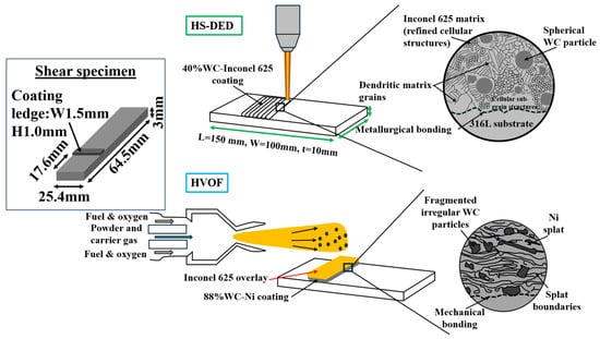
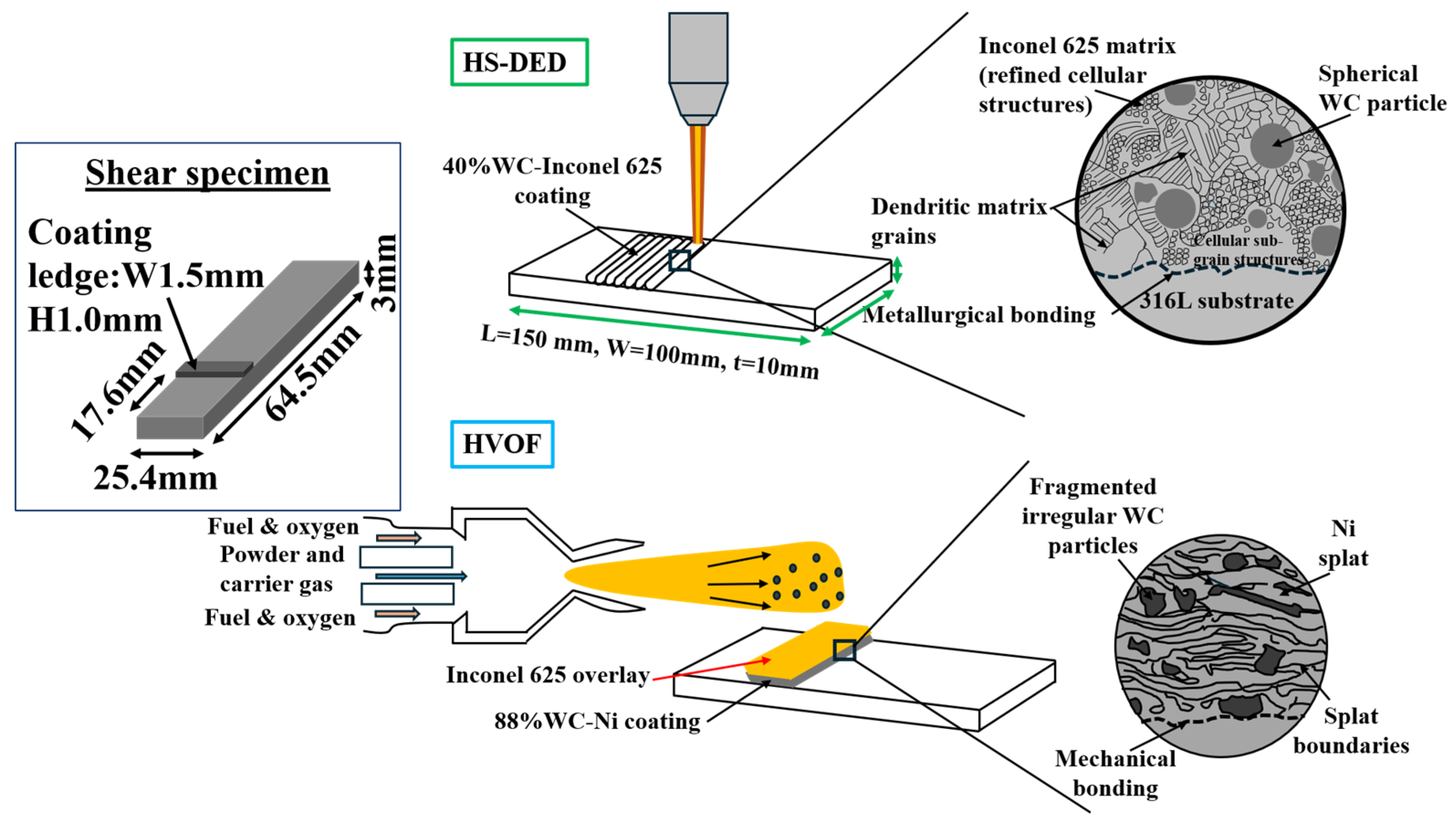
For comparison, WC-based coatings, deposited by high-velocity oxy-fuel (HVOF) spraying, were supplied by an industrial partner. These coatings consisted of a single layer with a nominal composition of 88 wt.% WC and 12 wt.% Ni deposited on a 316L stainless steel substrate and are denoted hereafter denoted as 88%WC-Ni_HVOF. The HVOF process parameters were independently optimized to achieve a representative industrial coating quality. The deposition strategies adopted for HS-DED (based on a line-by-line scanning pattern) and HVOF are schematically illustrated in Figure 1 (with their characteristic microstructure features being illustrated as well). Owing to the single-layer deposition limitation of the HVOF process, an additional overlay of pure Inconel 625 was deposited on top of the WC-Ni composite layer to a controlled thickness to enable proper specimen preparation for shear testing. The net-shape shear test specimen machined from the printed geometry is also illustrated in Figure 1, with dimensions following ASTM A264 [19] (an enlarged view is shown in Figure 2). The coating–substrate interface was carefully positioned to coincide with the intended shear plane. For all tests and characterizations, the HVOF and HS-DED coatings were conducted under identical conditions to enable a direct comparison of the microstructure, interfacial integrity, and mechanical performance.
Figure 1.
Schematic diagrams showing printing plan for both coatings, WC–Inconel 625 coating via HS-DED and WC-Ni coating via HVOF (with Inconel 625 overlay), with their characteristic microstructure features and a machined net-shape shear test specimen (dimensions indicated).
2.2. Testing Methodology
2.2.1. Cohesion Bond Strength Test—Bond Test
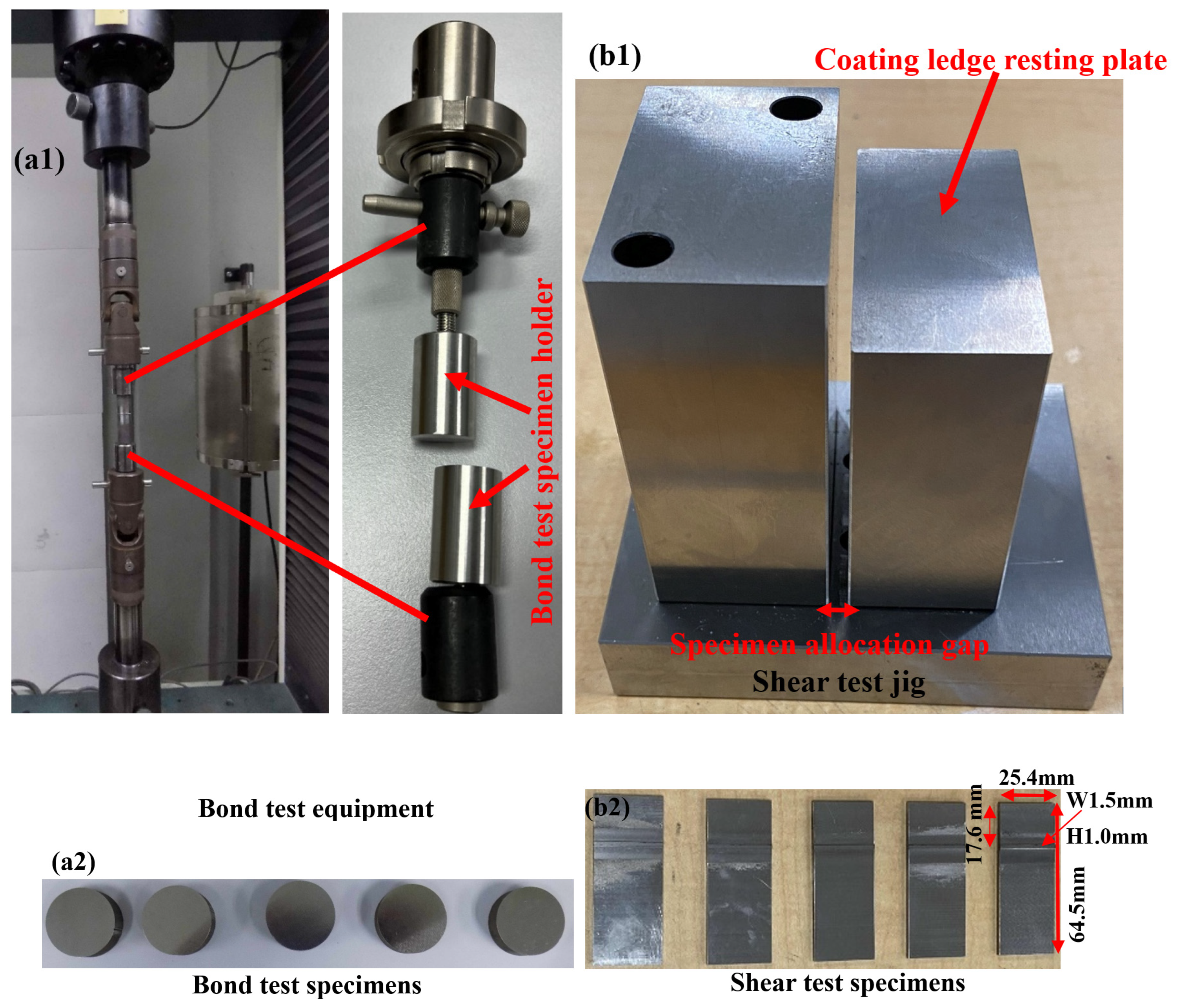
Cohesion bond strength (bond test) was evaluated using a standardized pull test in accordance with ASTM C633 [20] (Figure 2(a1)). The test specimens consisted of coated cylindrical buttons with a diameter of 25 mm, as illustrated in Figure 2(a2), together with the corresponding specimen holders. For both HS-DED and HVOF processes, the coatings were deposited as single layers to ensure consistency in testing conditions. The minimum bonding strength requirement specified in ASTM C633 is >10,000 psi, ~69 MPa.
2.2.2. Shear Bond Strength Test—Shear Test
As both HS-DED and HVOF coatings successfully passed the bond strength test, a shear bond strength test (shear test) was further conducted to evaluate the coating–substrate interfacial integrity under shear loading more stringently. The shear test was performed in accordance with ASTM A264. The shear test jig, designed in accordance with ASTM A264 and based on the geometry reported by Nellian et al. [21], was utilized and is shown in Figure 2(b1). The machined net-shape shear test specimens are shown in Figure 2(b2). The measured shear strength was calculated using maximum load (Fmax) divided by the nominal coating shear area (As), , where As = 25.4 mm × 1.5 mm.
Figure 2.
(a1) Cohesion bond strength—bond test setup; (a2) bond test specimen—coated button and specimen holders; (b1) shear bond strength test jig setup according to ASTM A264 standard, with dimensions given in previous work by Nellian et al. [21]; and (b2) the shear test specimens with the dimensions indicated.
2.3. Material Characterization
2.3.1. Microstructure Characterization
Specimens for microstructural characterization were sectioned using electrical discharge machining (EDM) and subsequently mechanically polished to an oxide polishing suspension (OPS) finish. Microstructural analysis was performed using field-emission scanning electron microscope (FE-SEM, JEOL 7600F, JEOL Ltd., Tokyo, Japan), coupled with energy dispersive X-ray spectroscopy (EDS) and electron backscatter diffraction (EBSD), and operated at an accelerating voltage of 20 kV and a probe current of 17 µA. EBSD data were acquired with a step size of 0.75 µm, and smaller step size of 0.3 µm was used to enable GND measurement.
EBSD/GND interpretation: LOMs were used to evaluate local lattice misorientation and estimate the associated GND density. No additional noise-removal procedure was applied. A misorientation threshold of 0.3° was used to distinguish very-low-angle grain boundaries (VLAGBs), consistent with the observed LOM distribution, in which most local misorientation values were below 0.3°. The calculated GND density should be regarded as a semi-quantitative estimate, particularly near the ~1 µm cellular structures, where the spatial resolution limits the accurate resolution of individual cell boundaries. Therefore, the EBSD results primarily demonstrate local lattice misorientation and relative GND accumulation rather than provide an exact measurement of total dislocation density.
Porosity and WC% measurement: A stitched optical micrograph covering the entire coating cross-section was used for image segmentation to minimize sampling bias. Grayscale thresholding in Keyence software (Keyence VHX-7000, Version 1.4, Osaka, Japan) was applied to distinguish WC particles, Inconel 625 matrix, and pores based on their image contrast. The threshold criteria were applied consistently throughout the stitched image. At approximately 100× magnification, the spatial resolution was ~0.5–1.5 µm/pixel, giving a minimum detectable pore size of approximately 1–5 µm. The dominant pores, typically ~10 µm, were therefore within the detection range and were further verified by SEM observations at ~1000× magnification.
2.3.2. Mechanical Test
Both bond and shear test specimens were in machined condition. For the bond test, sandblasting was applied to both flat surfaces of the coated buttons prior to adhesive (epoxy type with strength of 10,000–12,000 psi) application and curing (205 °C for 2 h after drying at 52 °C for 1 h) in order to enhance adhesion between the specimen and the loading fixtures. Both tests are conducted on a Shimadzu universal testing system (UTS) equipped with a 50 kN load cell. A constant crosshead displacement rate of 0.2 mm/min was applied until failure. Instead of tensile loading as used in the bond test, shear testing was conducted under compression loading.
Hardness: Hardness measurements were carried out using a Vickers hardness tester (Wilson VH3100, Buehler, Lake Bluff, IL, USA) under applied loads of 300 g and 500 g, with a dwell time of 15 s. Each reported hardness value represents the average of at least five independent indentations.
2.3.3. Phase Identification
Phase identification was performed by X-ray diffraction (XRD) using a Malvern Panalytical diffractometer (v5.3a, Malvern Panalytical Ltd., Great Malvern, UK) equipped with a Cu radiation source, operated at an accelerating voltage of 30 kV. XRD scans were collected with a step size of 0.05° for both feedstock powders and the 40 wt.% WC–Inconel 625 coatings. Quantitative phase analysis was conducted via Rietveld refinement using HighScore Plus software (Malvern Panalytical, Almelo, The Netherlands) to determine the retained WC content.
3. Results and Discussion
3.1. Coating Layer Morphology
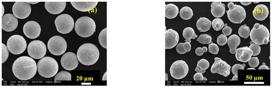
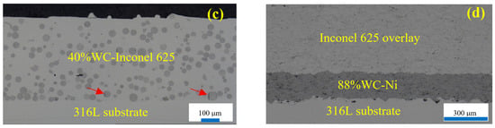
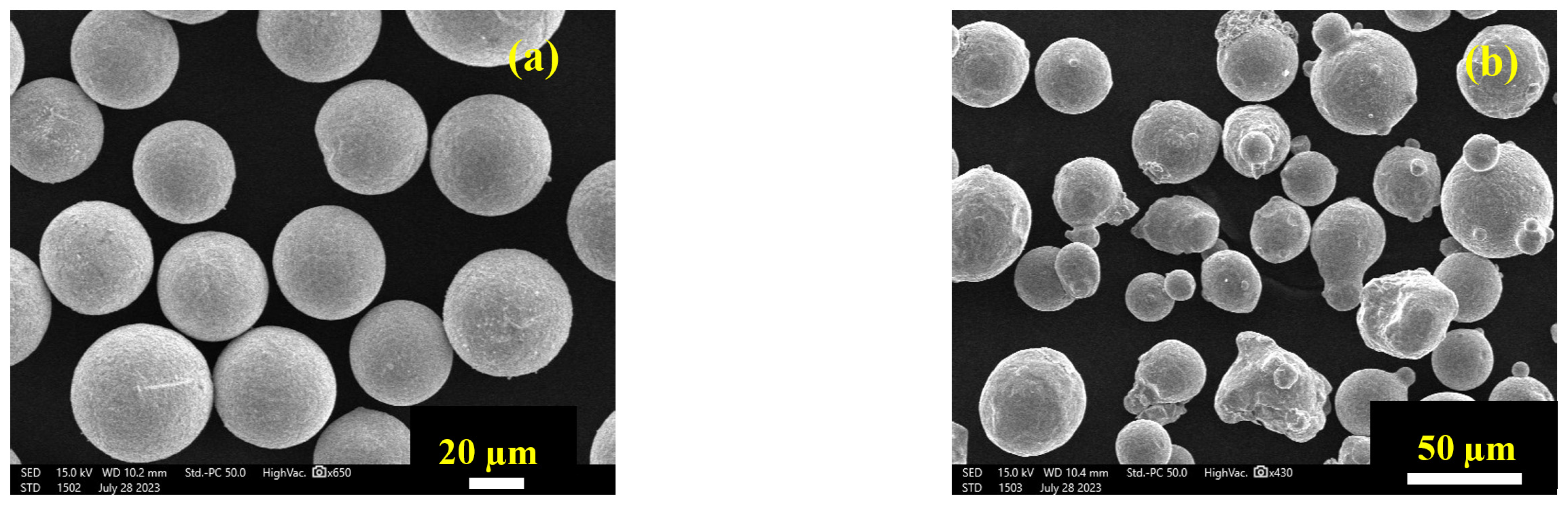
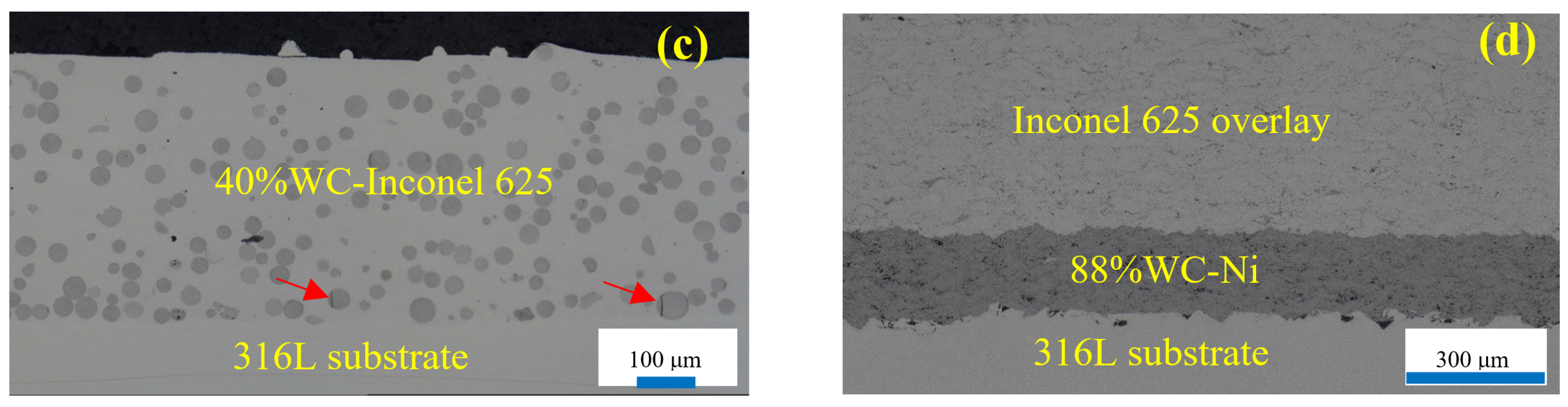
For HS-DED coating, both the WC and Inconel 625 powders used were near-spherical, 20–53 µm in size, and sourced from Makino, as shown in Figure 3a,b. Figure 3c shows a five-layer HS-DED MMC coating with 40 wt.% WC reinforcement (40%WC-Inconel 625_HS-DED). As observed, the WC particles are uniformly distributed throughout the Inconel 625 matrix, which can be attributed to the high scanning speed and the resulting short liquid-phase duration [13]. The short laser dwell time reduces the overall heat input and limits the volume and depth of the molten pool, with the deposited layer thickness being only ~70 µm. These conditions reduce the time available for the denser WC particles to settle or cluster at the bottom of the molten pool, helping to retain a relatively uniform particle distribution within the solidified Inconel 625 matrix. This homogeneous distribution is crucial for achieving excellent wear resistance. In addition, the relatively small thermal mass and heat conduction into the colder substrate promote rapid cooling and solidification of the liquid matrix, resulting in a fine microstructure. And very low porosity (<0.1%) was observed for the HS-DED coating, confirming the effectiveness of the optimized process parameters, as further demonstrated in the microstructure analysis.
Figure 3.
SEM images showing (a) WC powder and (b) Inconel 625 powder, with OM images showing (c) five layers of 40%WC-Inconel 625 coating via HS-DED, and (d) a single layer of 88%WC-Ni coating via HVOF (overlayed with Inconel 625 on top). Cracked WC particles are indicated by red arrows in (c).
A few cracked WC particles are observed (highlighted in Figure 3c), likely due to thermal shock effects, as the ceramic WC is prone to brittle fracture under rapid cooling. The high scanning speed also minimizes WC dissolution and promotes a refined matrix microstructure through a reduced peak temperature, brief high-temperature dwell, and rapid solidification [22]. The WC–Inconel 625 interface shows full metallurgical bonding, with no detectable pores or cracks.
In comparison, the HVOF-deposited 88%WC-Ni coating (with an Inconel 625 overlay to facilitate shear test) in Figure 3d exhibits finer WC particles due to smaller pre-alloyed powder size and fragmentation [23,24,25,26,27,28]. Residual porosity is higher (~1%), indicating a less dense structure than HS-DED. HVOF partially melts the powders, resulting in limited metallurgical bonding and primarily mechanical interlocking.
3.2. WC Particle Distribution Statistics
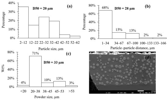
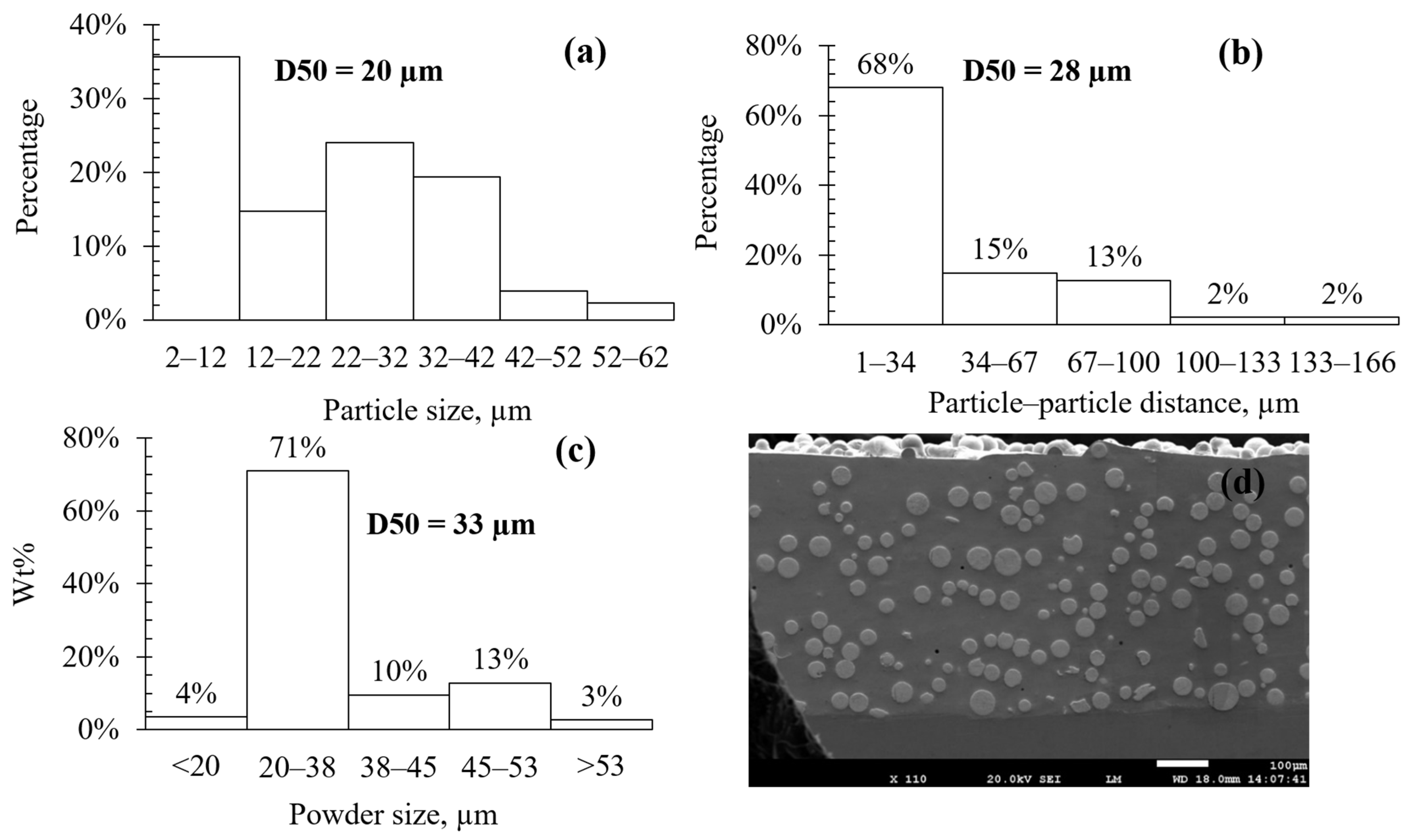
Quantitative analysis using ImageJ software (v2.18.0, Wayne Rasband, MD, USA) shown in Figure 4a,b reveals an average WC particle size of d50 = 20 µm (ranging from 1.5 to 53.8 µm) within the HS-DED coating (SEM image showing the analyzed area in Figure 4d), which was slightly smaller than the raw powder (20–53 µm and d50 = 33 µm, with powder size distribution shown in Figure 4c), indicating minor dissolution primarily from the outer edge during laser processing. The area fraction of WC was ~36%, using ImageJ software analysis. The average particle–particle distance was d50 = 28 µm (ranging 0.6–137 µm in Figure 4b), with some unavoidable particle agglomeration. This distribution is more uniform than conventional low-speed DED, where WC particles were observed being agglomerated at the bottom of the molten pool, forming heterogeneous structures [17]. Their overall distribution will be presented in a later section with the wear results.
Figure 4.
Histograms of remaining WC particles for (a) size distribution and (b) particle–particle distance for the sample 40%WC-Inconel 625_HS-DED, as well as the (c) WC powder size distribution and (d) SEM image showing the analyzed area for (a,b).
3.3. Phase Compositions
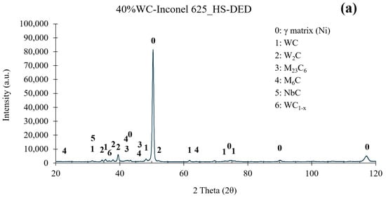
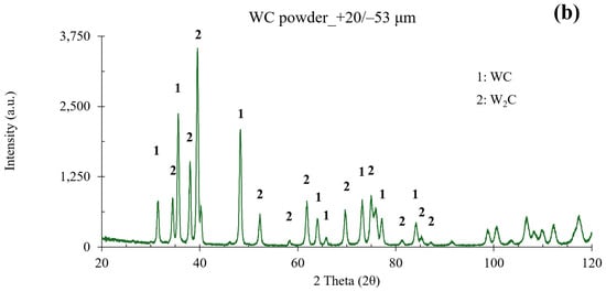
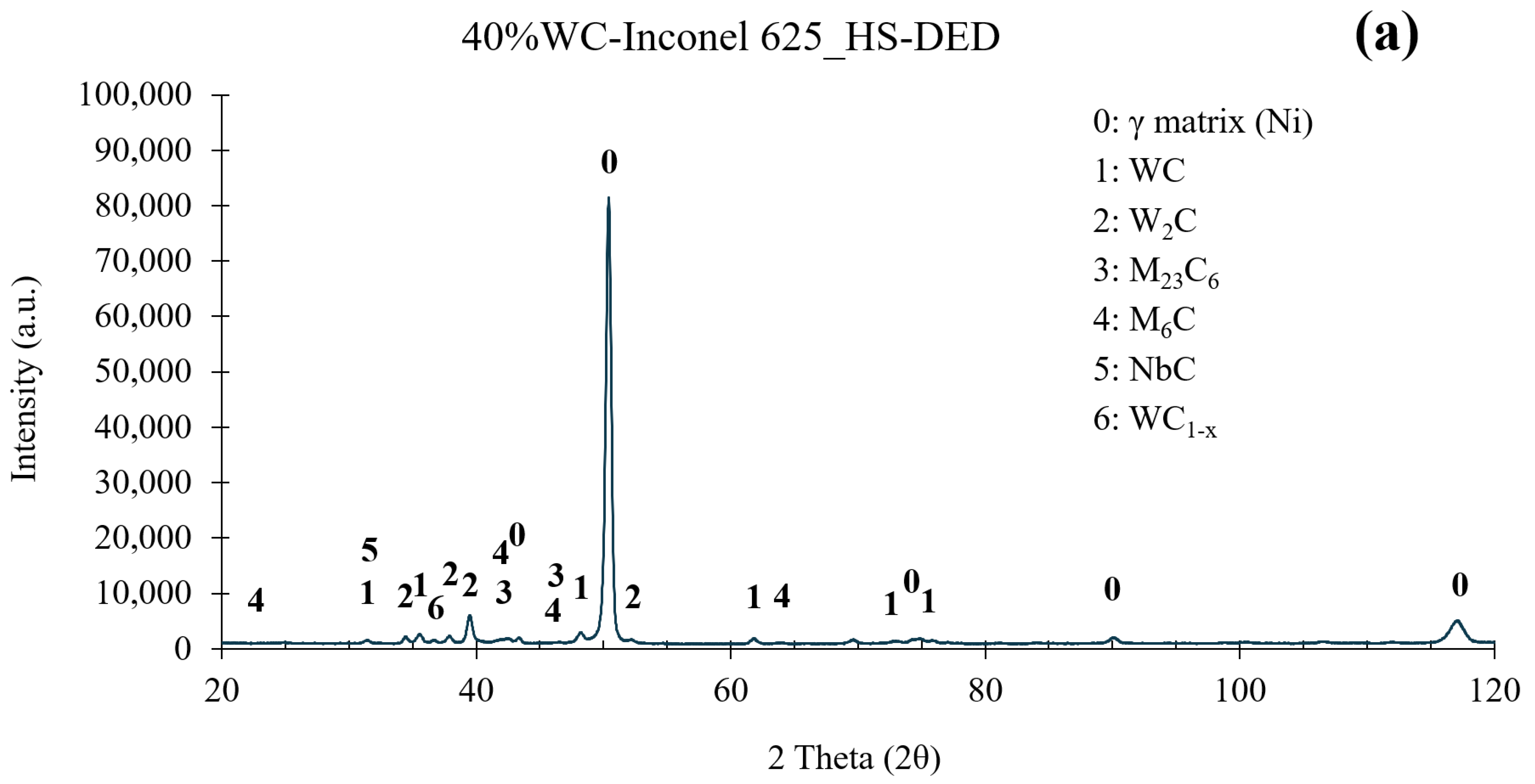
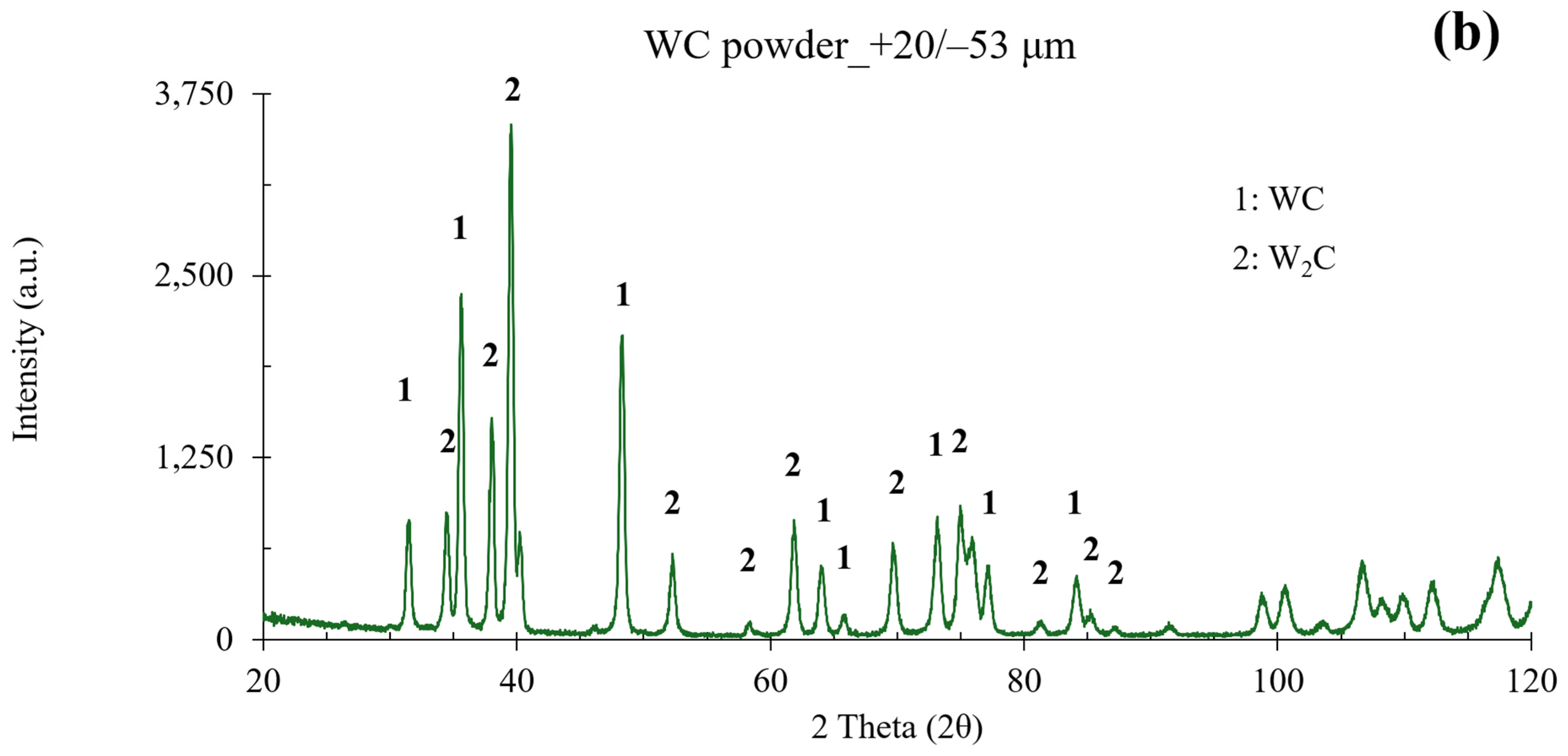
XRD analysis (Figure 5) confirmed the FCC γ-Inconel 625 matrix together with WC and W2C phases. Rietveld refinement gave a combined WC + W2C fraction of approximately 42.5 wt.%, close to the nominal 40 wt.% addition. However, it is not directly compared with above SEM analysis, as the two methods use different quantification approaches. The SEM and XRD results are therefore considered complementary, with SEM providing information on the spatial distribution of the WC-rich regions and Rietveld refinement providing quantitative information on the crystalline phase composition. The refinement showed approximately 70% WC and 30% W2C within the carbide phases. Although peak overlaps between carbide phases and their possible preferred orientations can introduce uncertainty in the refined fractions, the calculated and experimental diffraction profiles showed good agreement. The WC/W2C ratio changed from approximately 1:1 in the raw powder to 1.7:1 after deposition, suggesting partial carbide transformation during the high-temperature process or carbon redistribution/partial decarburization [17]. Overall, the high combined WC + W2C fraction indicates that most of the WC reinforcement was retained during HS-DED, with only limited phase transformation.
Figure 5.
XRD spectrum for (a) 40%WC-Inconel 625 coating via HS-DED, and (b) WC powder [17].
3.4. Microstructure and Grain Characteristics
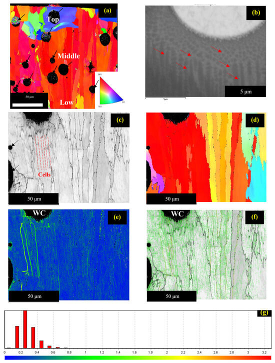
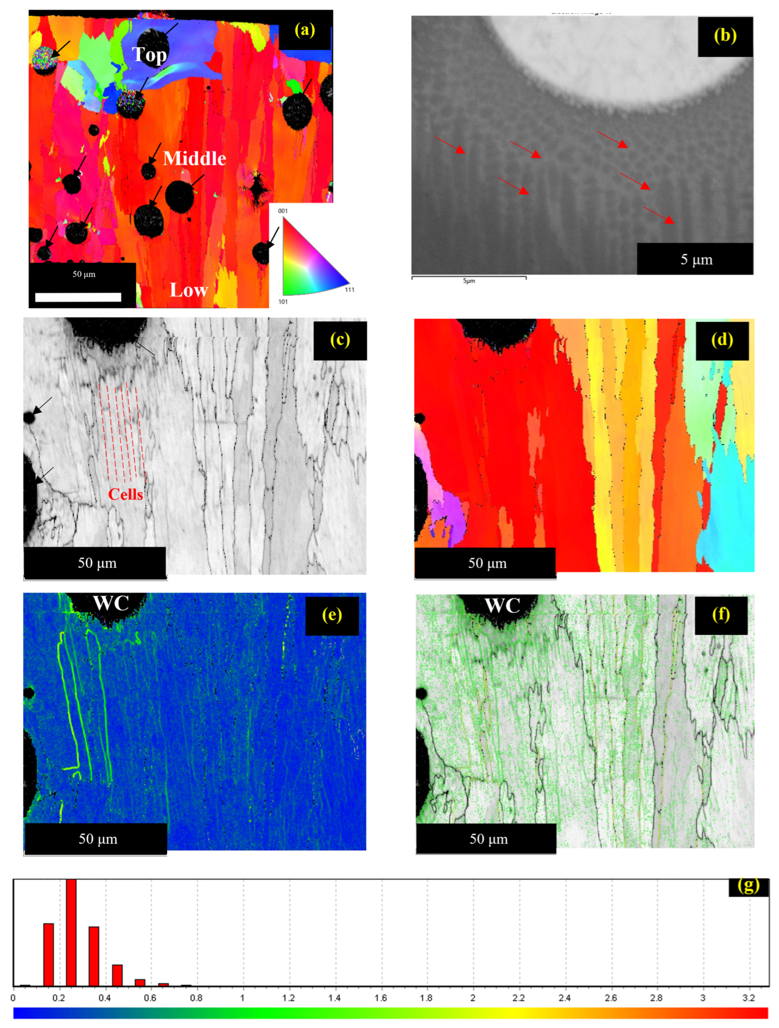
Microstructure: SEM and EBSD analyses reveals columnar grains growing preferentially along the (001) direction (Figure 6a) for the 40%WC-Inconel 625 coating fabricated by HS-DED. Epitaxial growth occurs across multiple layers, imparting strong texture to the Inconel 625 matrix, largely unaffected by embedded WC particles.
Figure 6.
Microstructure of 40%WC-Inconel 625_HS-DED, showing (a) IPF_Y coloring map from EBSD scanning, with the multi-layer coating from bottom to top (with inserted triangle legend), (b) SEM image showing the enlarged view of cellular structure around a WC particle, (c) BC map of the Inconel 625 matrix showing elongated columnar grains, (d) corresponding IPF-y coloring map with (c), (e) corresponding LOM showing GND disribution, (f) the GB map showing the VLAGBs in the range of <0.3°, and (g) the legend of LOM for (e). The black arrows in (a) indicate WC particles, while the red arrows in (b) indicate cellular boundaries with possible element segregation. Black arrows in (c) indicate unindexed WC particles.
Grain coarsening is observed from bottom to top of the coating due to preheating effects of previously deposited layers, with the top region displaying equiaxed grain growth. Columnar grains (~tens of microns) are significantly finer than those in conventional DED coatings, which can reach hundreds of microns or mm scale. Submicron cellular structures (<1 µm) with dense dislocation networks are evident (Figure 6b,c) and are delineated in Figure 6c, contributing to enhanced strength through impeded dislocation motion [29].
The HS-DED process achieves minimal substrate dilution (~30 µm) and shallow WC surface reactions, preserving reinforcement integrity. The height of each building layer (coating height above substrate) is about 70 µm under the current process settings, which can be tunable through changing of laser power, powder flow rate, etc. EBSD local misorientation maps (LOMs) indicate geometrically necessary dislocations (GNDs) (Figure 6e; with the legend shown in Figure 6g) concentrated along cellular boundaries, WC–Inconel 625 interfaces, and high-angle grain boundaries (HAGBs > 15°), supporting improved mechanical performance. The very-low-angle grain boundaries (VLAGBs) shown in Figure 6f usually indicate substructures; that is, the cells. In this study, <0.3° is defined, which corresponds well with the LOMs (Figure 6g) [30].
Dislocation density: Due to the higher cooling rate induced by the HS-DED process than conventional DED, the dislocation density is further calculated through misorientation angle θ, measured from EBSD LOM using the following equation
according to Kubin and Mortensen et al. [31] and based on strain gradient model proposed by Gao et al. [32,33]. X is unit length and α is constant taken to be two (assuming for pure tilt boundary) [34]. The only counted dislocation density is GND [35] and not statistical stored dislocation (SSD) due to the misorientation measurement method used in EBSD. This equation is further simplified as ρGND = 2θ/(bu), where u is step size (0.3 µm). The calculated GND density is 1.37 × 10¹⁴, which can then be input into the equation below for the calculation of dislocation strengthening [36]:
where k is constant (0.38), µ is shear modulus of the Inconel 625 matrix (µ = 81.4 GPa), b is Burgers vector of pure Ni matrix (b = 0.254 nm), and ρ is dislocation density. The calculated strength from dislocation is about 92 MPa.
3.5. Mechanical Properties
3.5.1. Interface Bonding Strength
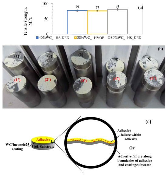
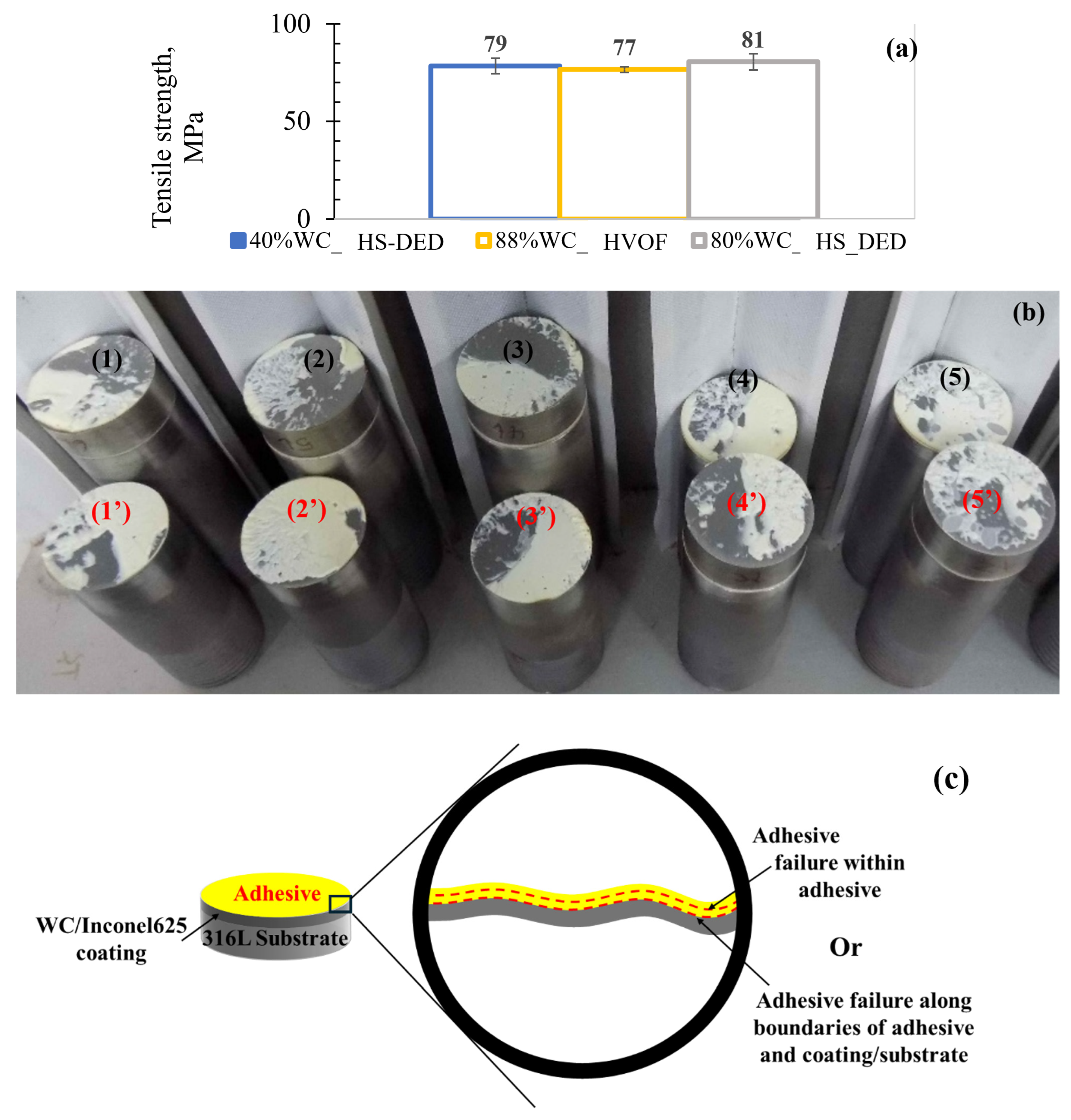
Bond test results: Figure 7a presents the bond test (ASTM C633) results, and shows all samples exceeded 10,000 psi (69 MPa), as required by ASTM C633 for coating’s minimum expected strength. All samples failed adhesively at the interface or within the adhesive itself, as seen from the fractured surface shown in Figure 7b, for both HS-DED and HVOF coatings. The failure mode is further illustrated in Figure 7c. No MMC coating failure occurred, indicating good interfacial adhesion for both HS-DED and HVOF processes.
Figure 7.
(a) Cohesion bonding strength—bond test results, averaged on five specimens for each coating; (b) the broken bond test specimens for 40%WC-Inconel 625_HS-DED coating (1–5) and 88%WC-Ni_HOVF coating (1′–5′); (c) the illustrated fracture mode showing adhesive failure between adhesive and coating/substrate or within adhesive. No MMC coating failure is observed.
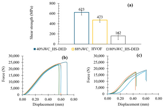
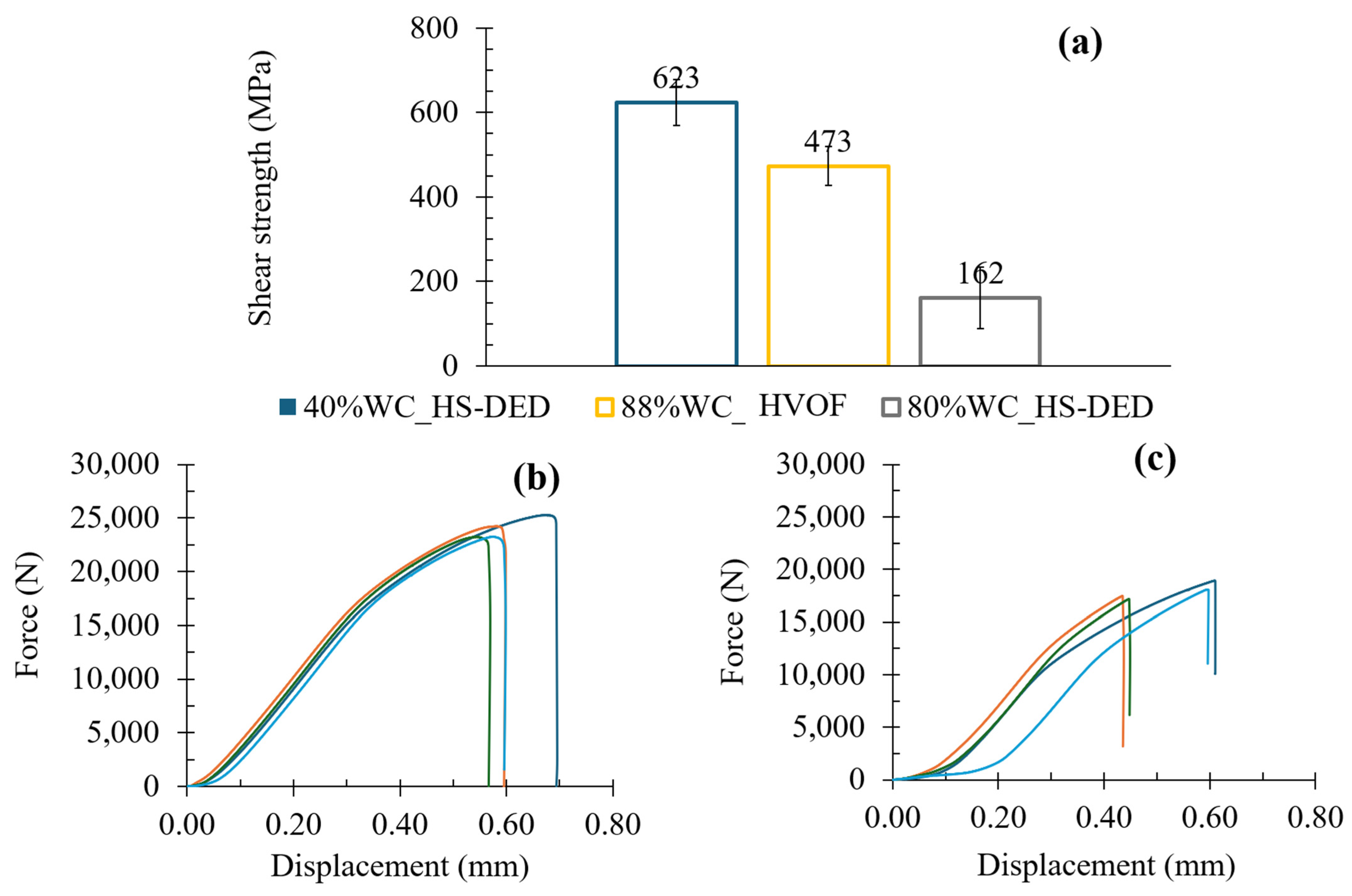
Shear test results: Shear test (ASTM A264) quantifies the interface strength. The HS-DED 40%WC-Inconel 625 coating exhibited a higher shear strength (623 MPa) [37] and greater deformation distance than the HVOF coatings (Figure 8a–c), indicating metallurgical bonding. The WC particles were predominantly fractured during the shear test, as will be discussed later, from the fractured surface of the HS-DED coatings via brittle failure, indicating metallurgical bonding between WC particles and the Inconel 625 matrix with an uptake in the shear loading [38].
Figure 8.
(a) Shear strength obtained for three coatings: 40%WC-Inconel 625_HS-DED, 88%WC-Ni_HVOF, and 80%WC-Inconel 625_HS-DED with an error bar (each coating averaged from five specimens). Loading–displacement curves for coatings (b) 40%WC-Inconel 625_HS-DED and (c) 88%WC-Ni_HVOF. The different colors of the loading-displacement curves are representing different test specimens.
HVOF coatings displayed a lower shear strength due to weak mechanical bonding, high porosity, and limited metallic matrix content. Higher WC-loaded coatings (e.g., 80%WC-Inconel 625_HS-DED) showed a lower strength due to pre-existing cracks and brittle behavior, confirming the importance of balanced WC content [39].
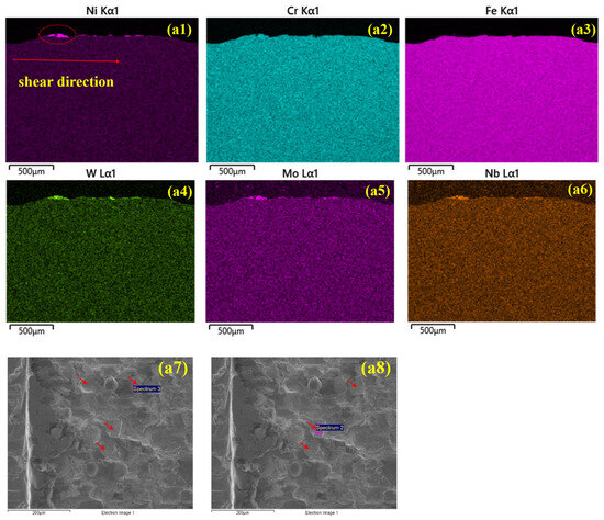
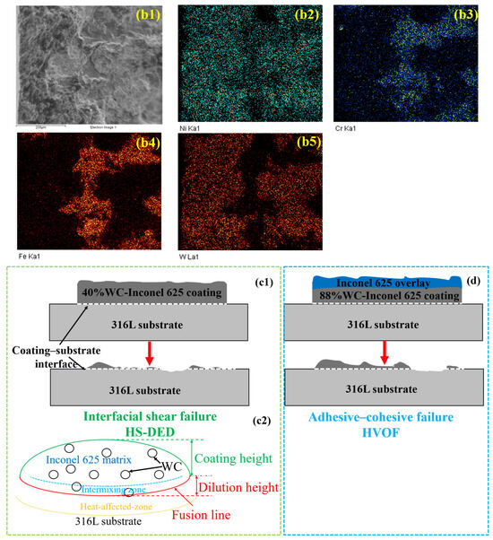
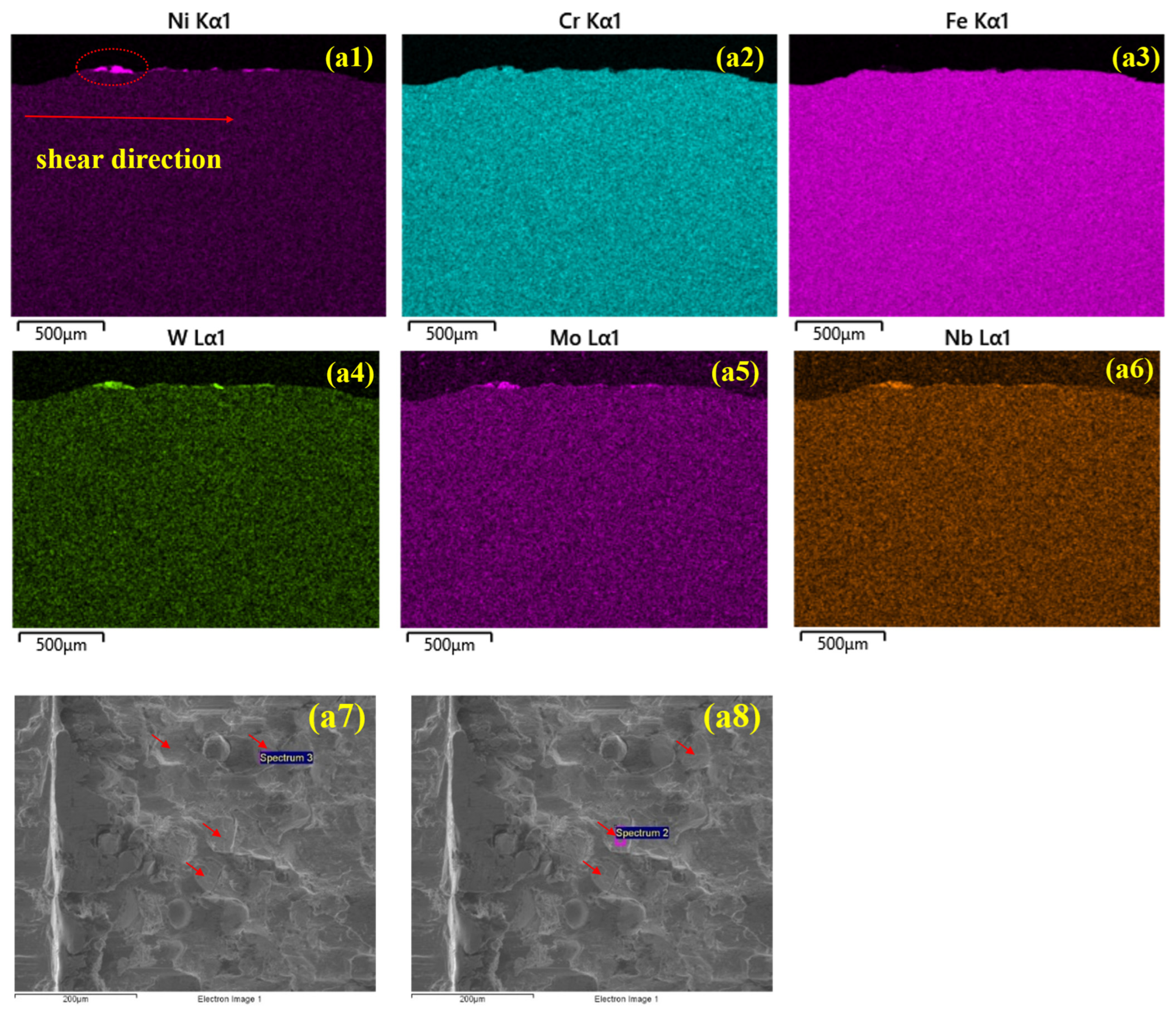
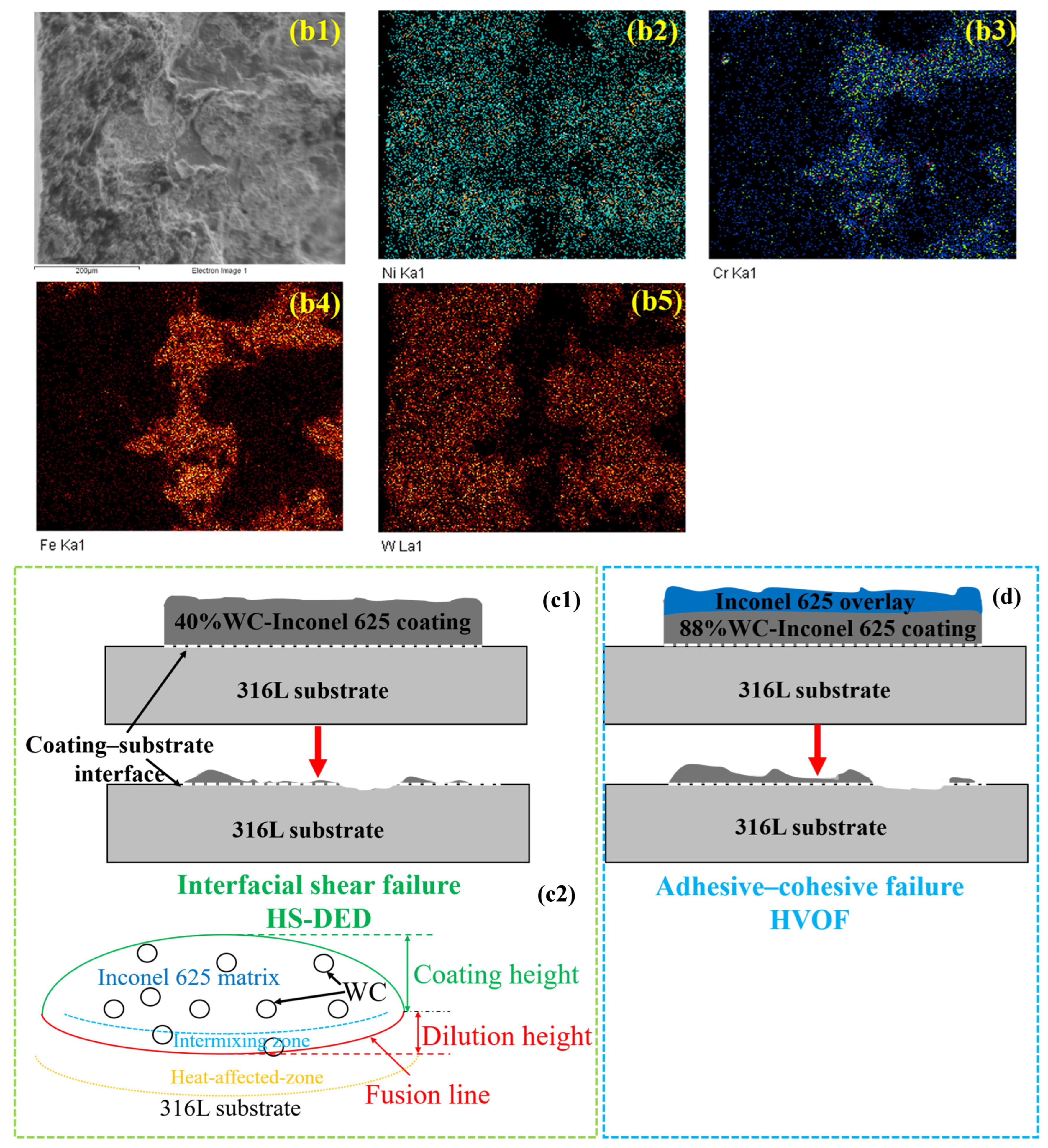
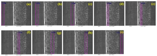
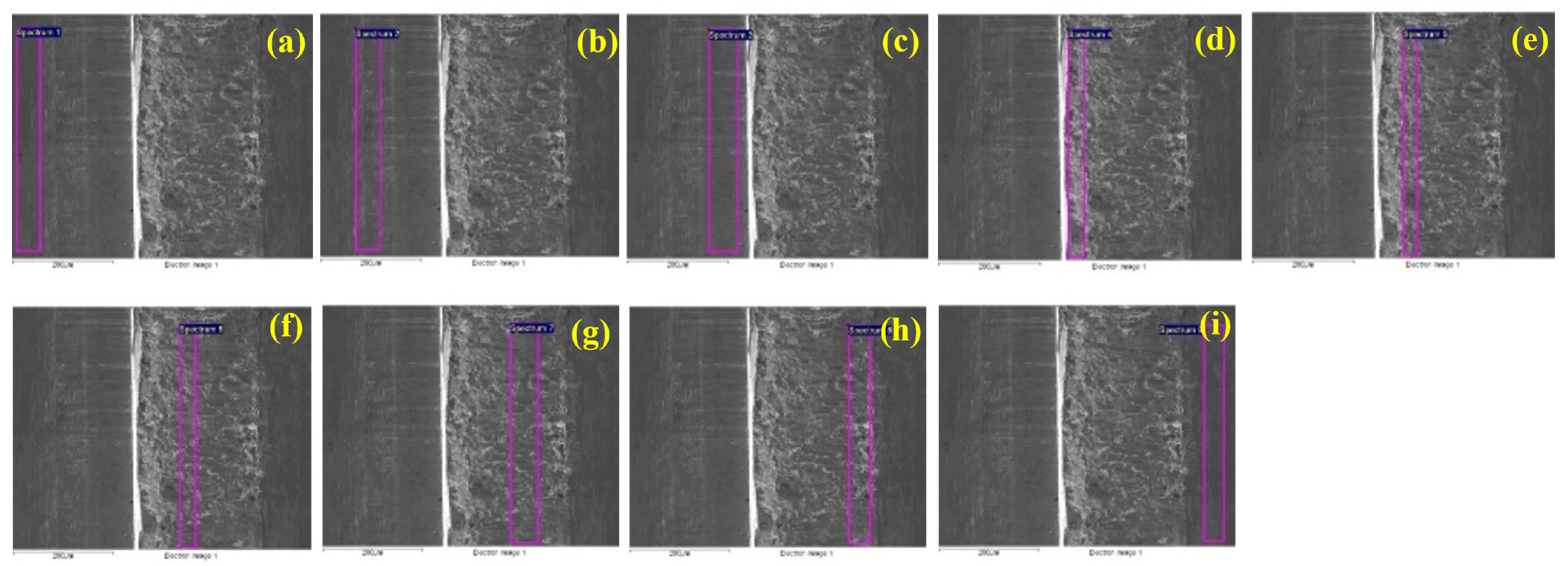
Fracture analysis of shear test samples: Cross-sectional EDS mapping along the fractured path of shear tested samples showed that cracks in HS-DED 40%WC-Inconel 625 coatings propagated tortuously along the coating–substrate interface, mostly within the shallow dilution/intermixing zone (~15 µm), with crack initiation in WC-rich coating regions (Figure 9(a1–a8) and highlighted in Figure 9(a1)) [40,41]. The tortuous path and metallurgical bonding enhanced interfacial fracture resistance. EDS analysis along the top fracture surface showed similar conclusions, as summarized in Table 2, with corresponding areas shown in Figure 10.
Figure 9.
(a1–a6) Cross-sectional EDS mappings along fractured path for elements Ni, Cr, Fe, W, Mo, and Nb for 40%WC-Inconel 625_HS-DED coating; (a7,a8) top fractured surface SEM images for 40%WC-Inconel 625_HS-DED coating, showing fractured WC particles (indicated with red arrows); (b1–b5) SEM image and EDS mappings of elements Ni, Cr, Fe, and W along the top fractured surface for 88%WC-Ni_HVOF coating; illustrative diagrams for the shear test failure mode for coatings 40%WC-Inconel 625_HS-DED (c1) and 88%WC-Ni_HVOF (d); and (c2) the regimes defined along the coating–substrate interface for 40%WC-Inconel 625_HS-DED.
Figure 10.
EDS-analyzed areas (a–i) corresponding to a–i in Table 2 with the areas highlighted in purple rectangular blocks.
HVOF 88%WC-Ni coatings fractured primarily within the coating layer (as seen from the EDS analysis results of the top fractured surface in Figure 9(b1–b5)) due to higher porosity and weaker mechanical bonding. Minimal substrate intermixing was observed, and crack propagation occurred along pre-existing defects. Overall, HS-DED coatings demonstrated superior fracture behavior, with shallow dilution, metallurgical bonding, and uniform WC distribution, mitigating brittle failure and enhancing interface strength. Their failure mechanisms were further illustrated in Figure 9(c1,d) for both processes (shown with before and after the test). The fractured WC particles are highlighted with red arrows in Figure 9(a7,a8) and the different regimes for the HS-DED coatings are illustrated in Figure 9(c2).
3.5.2. Hardness
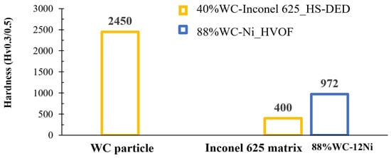
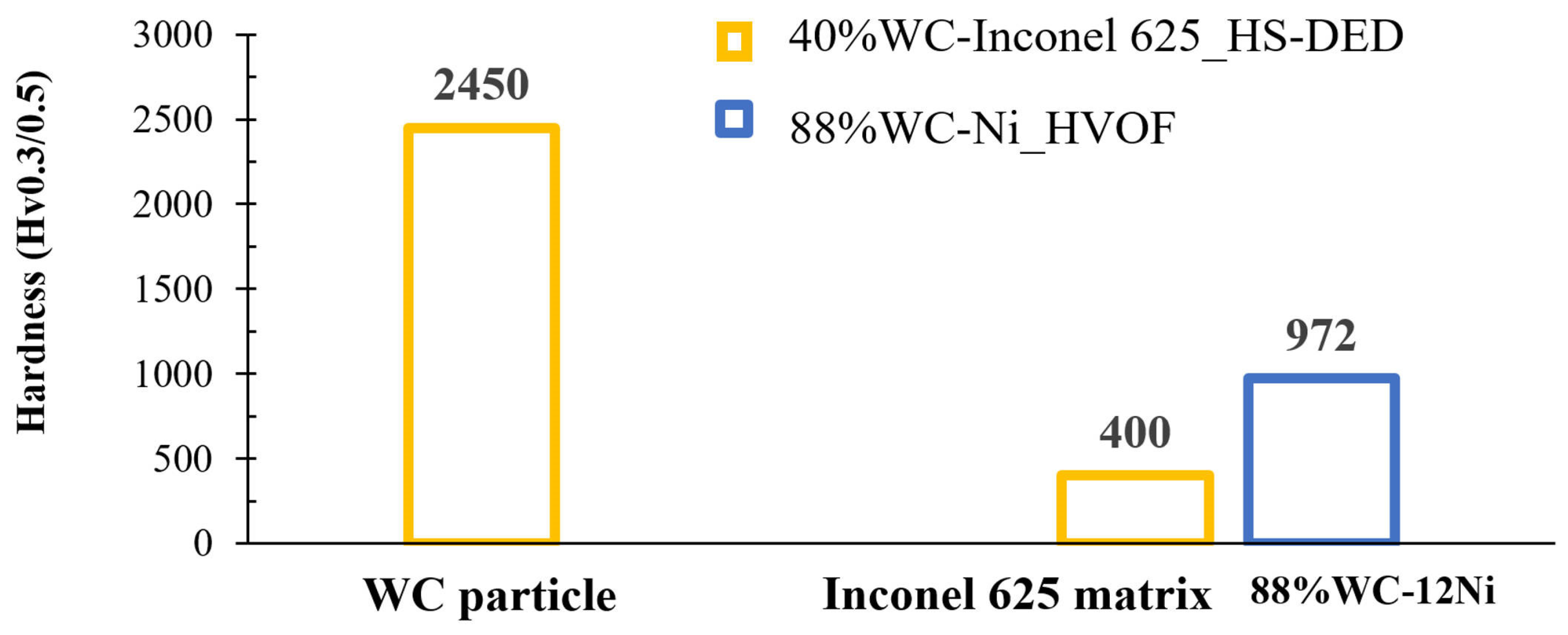
Coatings: Figure 11 shows the hardness measurement results of the two coatings. 88%WC-Ni_HVOF coatings exhibited high hardness (~972 HV0.5) due to a high WC content and its wide distribution. HS-DED 40%WC-Inconel 625 coatings showed dual-phase hardness—WC (~2450 HV0.3) and Inconel 625 (~400 HV0.3)—combining strength and ductility [24,42]. A higher WC content (≥80%) induced cracking due to the reduced metallic matrix [8,39].
Figure 11.
Hardness of WC particles, Inconel 625 matrix, and 88%WC-12Ni matrix for coatings 40%WC-Inconel 625_HS-DED and 88%WC-Ni_HVOF.
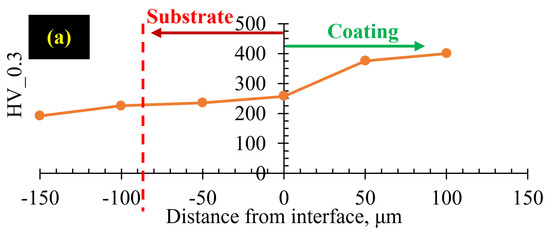
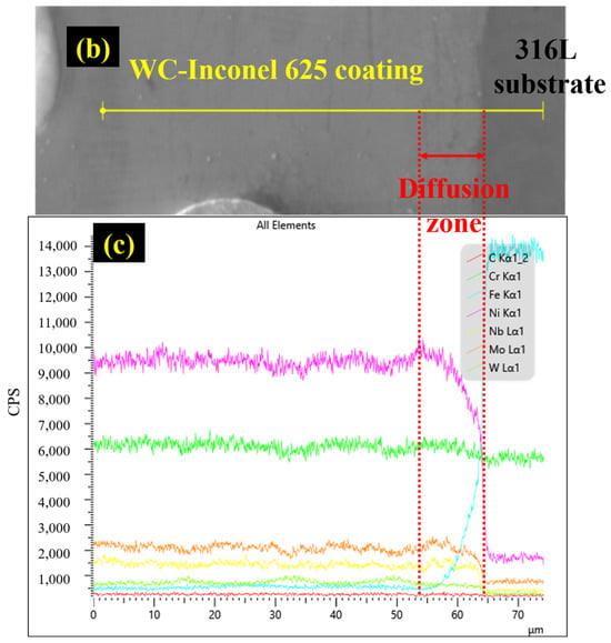
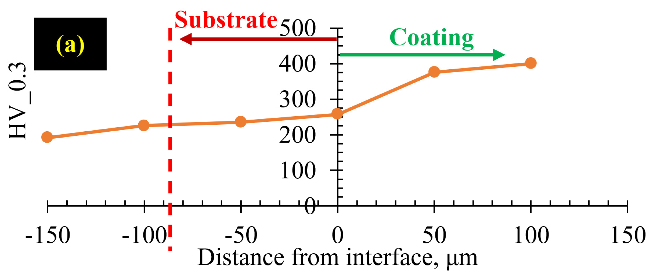
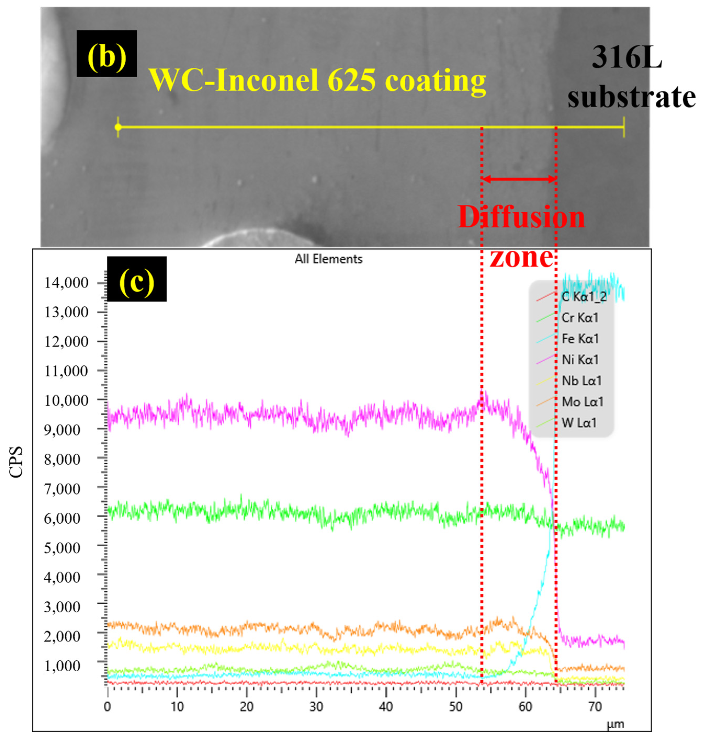
Coating–substrate interface: Figure 12a shows that hardness across the interface increased gradually from the 316L substrate (HV192) to the HS-DED coating (HV257) over a ~150 µm region, reflecting laser shock peening and minimal thermal effects [43]. This is consistent with the microstructure study from our previous work using EBSD [17]. Intermixing with Fe (a thin layer) from the substrate slightly reduced the Inconel 625 coating’s hardness near the interface. The result is consistent with element analysis via EDS, as shown in Figure 12b,c, highlighting the element diffusion zone with a larger concentration of Fe in the coated area near the interface.
Figure 12.
(a) Hardness profile across the coating–substrate interface within a region of −150 to +150 µm for the 40 wt.% WC-Inconel 625_HS-DED coating, and (b,c) SEM/EDS line scan results showing the distributions of Fe, Ni, Cr, Mo, Nb, W, and C across the interface. A diffusion/transition zone (indicated by red dashed straight lines) extending over several tens of micrometers can be observed, characterized by gradual concentration gradients.
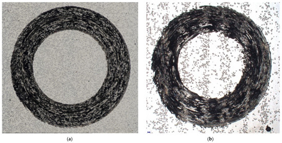
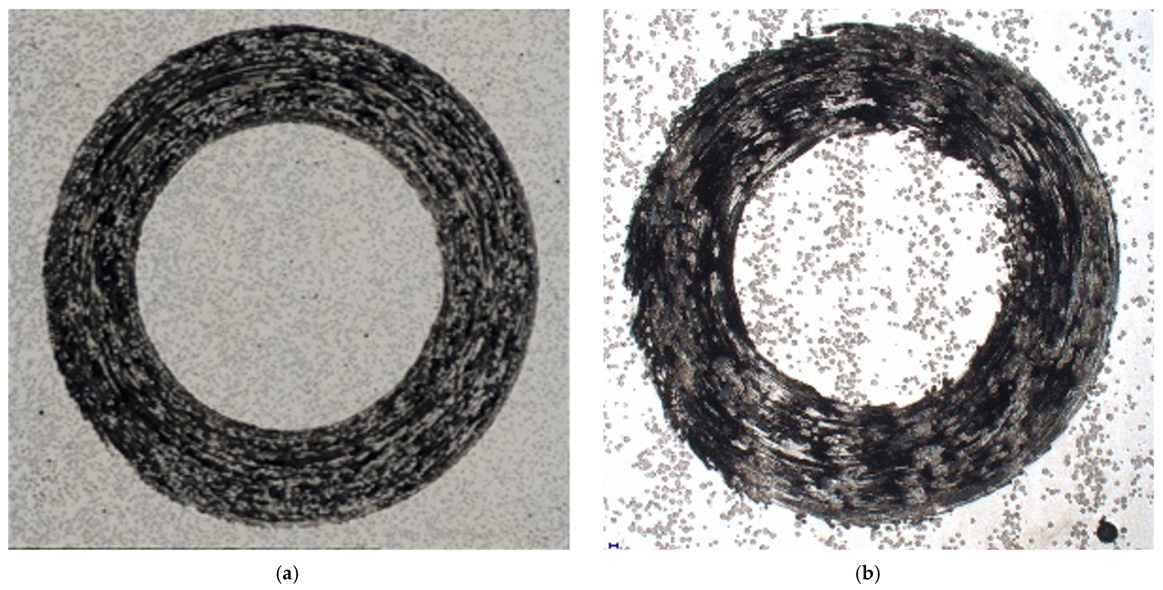
Wear performance: The wear test has been reported in previous work. Here, the results of wear for both HS-DED and conventional DED are summarized in Table 3. Using conventional Archard’s wear equation for coatings [44] as Q = K × Fn/Hc, where Q is wear rate in the unit of mm3/N·m, K is dimensionless wear coefficient, Fn is normal applied load in N, and Hc is the composite hardness (N/mm2) obtained using linear rule of mixture Hc = VWCHWC + (1 − VWC)HInconel 625, where VWC is volumetric fraction of WC (36% from above SEM analysis), HWC is WC hardness, and HInconel 625 is Inconel 625 matrix hardness. Using the experimental wear rates, applied loads, and calculated composite hardnesses, the HS-DED coating exhibited a substantially lower wear rate of mm3/N·m compared to mm3/N·m for the conventional DED coating, corresponding to approximately 75% reduction in wear rate. The calculated wear coefficient of the HS-DED coating was consequently lower than that of the conventional DED coating and was within the range reported for HVOF coatings (– mm3/N·m) [45,46] despite the substantially higher WC content typically used in HVOF coatings. The improved wear resistance of the HS-DED coating is attributed to the combined effects of the relatively hard Inconel 625 matrix, more homogeneous distribution of WC particles within the matrix, and lower defect content, which can reduce localized damage and WC particle pull-out during sliding. The wear tracks of the HS-DED and conventional DED coatings are shown in Figure 13.
Table 3.
Wear test results for WC–Inconel 625 coatings produced by HS-DED and DED.
Figure 13.
Wear test results showing wear tracks (OM image) for coatings produced by (a) HS-DED and (b) DED with 40%WC within the IN625 matrix.
4. Conclusions
This study demonstrates the successful fabrication of high-quality WC-reinforced Inconel 625 MMC coatings using a novel HS-DED process. The main findings are summarized as follows:
- Microstructure and phase integrity: HS-DED coatings exhibited uniform WC particle distribution within the Inconel 625 matrix, minimal porosity (<0.1%) and metallurgical bonding at the coating–substrate interface. Minor dissolution of WC occurred primarily for smaller particles, while larger particles remained intact. The Inconel 625 matrix showed refined columnar grains with submicron cellular structures, promoting strength via dislocation hardening.
- Mechanical properties: HS-DED 40%WC-Inconel 625 coatings achieved superior interface strength, with a shear strength of 623 MPa with enhanced ductility, outperforming conventional HVOF coatings. Dual-phase hardness (WC: ~2450 HV, Inconel 625: ~400 HV) balanced wear resistance and toughness. Higher WC loadings (>40%) reduced mechanical performance due to increased brittleness and defects, such as crack formation.
- Fracture behavior: Fracture analysis revealed tortuous crack propagation along the coating–substrate interface for HS-DED coatings, mitigated by shallow dilution and metallurgical bonding. In contrast, HVOF coatings failed primarily within the coating due to high porosity, weak particle bonding, and limited metallic matrix content.
Overall, the HS-DED process enables the production of WC–Inconel 625 MMC coatings with enhanced interfacial strength, hardness combined with good ductility, and microstructural integrity compared to conventional HVOF coatings. The combination of a high scanning speed for controlled thermal input with optimized process parameters effectively preserves reinforcement, refines microstructure, and minimizes defects, demonstrating the potential of HS-DED for high-performance MMC coatings in wear-resistant and structural applications.
Author Contributions
Conceptualization, J.W., N.A.S., E.Z.E.T. and J.H.L.P.; methodology, J.W., N.A.S., E.Z.E.T. and J.H.L.P.; software, J.W., N.A.S.; validation, J.W., N.A.S., E.Z.E.T. and J.H.L.P.; formal analysis, J.W., N.A.S.; investigation, J.W., N.A.S.; resources, N.A.S., E.Z.E.T. and J.H.L.P.; data curation, J.W., N.A.S.; writing—original draft preparation, J.W.; writing—review and editing, J.W., N.A.S., E.Z.E.T. and J.H.L.P.; visualization, J.W.; supervision, N.A.S., E.Z.E.T. and J.H.L.P.; project administration, N.A.S., E.Z.E.T. and J.H.L.P.; funding acquisition, N.A.S., E.Z.E.T. and J.H.L.P. All authors have read and agreed to the published version of the manuscript.
Funding
This research was funded by Makino-NTU joint project funding, as well as cash and in-kind contributions from the School of Mechanical and Aerospace Engineering, NTU, and Makino Asia Pte Ltd., Singapore.
Data Availability Statement
All data generated or analyzed during this study are included in the article and are available from the corresponding author on reasonable request.
Acknowledgments
The authors would like to acknowledge the RIE2025 Manufacturing, Trade and Connectivity (MTC) Industry Alignment fund Pre-Positioning (MTC-IAF-PP) Grant No. M24N2a0018 for supporting the research work. The lead PI, John H. L. PANG, would like to thank the School of Mechanical and Aerospace Engineering and Nanyang Technological University, Singapore for hosting and providing research support for the MTC-IAF-PP projects.
Conflicts of Interest
The authors declare that this research was funded by Makino Asia Pte. Ltd. The company provided the materials used in this study, conducted the experimental work, and contributed to the analysis and interpretation of the experimental results. The authors had access to the study data and jointly contributed to the analysis, interpretation, and preparation of the manuscript. The authors declare no other competing interests.
References
- Sharifitabar, M.; Khorshahian, S.; Shafiee Afarani, M.; Kumar, P.; Jain, N.K. High-temperature oxidation performance of Inconel 625 superalloy fabricated by wire arc additive manufacturing. Corros. Sci. 2022, 197, 110087. [Google Scholar] [CrossRef] [Scilit]
- Kim, T.-H.K.K.-S.; Kassner, M.E.; Son, K.-T.; Lee, K.-A. High-temperature tensile and high cycle fatigue properties of inconel 625 alloy manufactured by laser powder bed fusion. Addit. Manuf. 2020, 35, 101377. [Google Scholar] [CrossRef] [Scilit]
- Verwimp, J.; Rombouts, M.; Geerinckx, E.; Motmans, F. Applications of Laser Cladded WC-Based Wear Resistant Coatings. Phys. Procedia 2011, 12, 330–337. [Google Scholar] [CrossRef] [Scilit]
- Huebner, J. Inconel 625—Tungsten Carbide Composite System for Laser Additive Manufacturing. Ph.D. Thesis, Department of Ceramics and Refractories, Faculty of Material Science and Ceramics, AGH University of Science and Technology, Kraków, Poland, 2020. [Google Scholar]
- Abioye, T.E. Laser Deposition of Inconel 625-Tungsten Carbide Composite Coatings by Powder and Wire Feedstock. Doctoral Dissertation, Department of Mechanical, Materials and Manufacturing Engineering, The University of Nottingham, Nottingham, UK, February 2014. [Google Scholar]
- Casati, R.; Coduri, M.; Lecis, N.; Andrianopoli, C.; Vedani, M. Microstructure and mechanical behavior of hot-work tool steels processed by Selective Laser Melting. Mater. Charact. 2018, 137, 50–57. [Google Scholar] [CrossRef] [Scilit]
- Zhang, D.; Zhang, X. Laser cladding of stainless steel with Ni–Cr3C2 and Ni–WC for improving erosive–corrosive wear performance. Surf. Coat. Technol. 2005, 190, 212–217. [Google Scholar] [CrossRef] [Scilit]
- Vijay, P.; Raju, K.V.B.; Ramji, K.; Kamaluddin, S. Effect of tungsten carbide on Al6061-SiC hydrid metal matrix omcposites. Compos. Theory Pract. 2021, 21, 169–180. [Google Scholar]
- Huebner, J.; Rutkowski, P.; Kata, D.; Kusiński, J. Microstructural and Mechanical Study of Inconel 625—Tungsten Carbide Composite Coatings Obtained by Powder Laser Cladding. Arch. Metall. Mater. 2017, 62, 531–538. [Google Scholar] [CrossRef] [Scilit]
- Gao, Y.; Zhen, B.; Xu, J.; Ding, Y.; Lu, X. Achieving strength–ductility synergy and enhanced intergranular corrosion resistance in the Inconel 625 alloy via twin boundary tailoring. J. Mater. Res. Technol. 2025, 35, 3728–3740. [Google Scholar] [CrossRef] [Scilit]
- Wu, G.; Ding, K.; Qiao, S.; Wei, T.; Liu, X.; Gao, Y. Weakening modes for the heat affected zone in Inconel 625 superalloy welded joints under different high temperature rupture conditions. J. Mater. Res. Technol. 2021, 14, 2233–2242. [Google Scholar] [CrossRef] [Scilit]
- Jiang, W.H.; Kovacevic, R. Laser deposited TiC/H13 tool steel composite coatings and their erosion resistance. J. Mater. Process. Technol. 2007, 186, 331–338. [Google Scholar] [CrossRef] [Scilit]
- Sun, J.; Li, Z.; Wu, D.; Komen, H.; Tanaka, M.; Volpp, J.; Luo, G.; Zhang, Y.; Ma, N.; Jiao, W.; et al. High-speed laser-directed energy deposition of crack-free wear-resistant and anti-corrosive Al/Cu bimetal components. Virtual Phys. Prototyp. 2024, 20, e2438885. [Google Scholar] [CrossRef] [Scilit]
- Cho, W.-I.; Park, C. A Review of Directed Energy Deposition for Wear-Resistant Metal–Ceramic Coatings in High-Temperature Industrial Applications. Metals 2026, 16, 403. [Google Scholar] [CrossRef] [Scilit]
- Ribeiro, K.S.B.; Reghini, A.C.; Coelho, R.T. An analytical model for estimating process parameters input in L-DED based on bead geometry. Manuf. Lett. 2024, 41, 742–752. [Google Scholar] [CrossRef] [Scilit]
- Bu, X.Y.; Xu, X.; Lu, H.F.; Cai, J.; Deng, W.W.; Xing, F.; Luo, K.Y.; Lu, J.Z. Extreme high-speed-rate laser directed energy deposition of high strength low carbon stainless steel coating with layered heterogeneous structure. Mater. Sci. Eng. A 2022, 859, 144203. [Google Scholar] [CrossRef] [Scilit]
- Wang, J.; Subramaniam, N.A.; Tan, E.Z.E.; Pang, J.H.L. High-speed laser metal deposited tungsten carbide-Inconel 625 coating with refined microstructure and enhanced wear for high temperature performance. Int. J. Adv. Manuf. Technol. 2025, 140, 6807–6827. [Google Scholar] [CrossRef] [Scilit]
- Li, M.; Huang, K.; Yi, X. Crack Formation Mechanisms and Control Methods of Laser Cladding Coatings: A Review. Coatings 2023, 13, 1117. [Google Scholar] [CrossRef] [Scilit]
- ASTM A264-12; Standard Specification for Stainless Chromium-Nickel Steel-Clad Plate. ASTM International: West Conshohocken, PA, USA, 2026.
- ASTM C633-13; Standard Test Method for Adhesion or Cohesion Strength of Thermal Spray Coatings. ASTM International: West Conshohocken, PA, USA, 2021.
- Nellian, A.S.; Pang, J.H.L. Laser metal deposition characterization study of metal additive manufacturing repair of rail steel specimens. Virtual Phys. Prototyp. 2022, 18, e2134042. [Google Scholar] [CrossRef] [Scilit]
- Fu, J.; Zhang, L.; Wang, H.; Zhao, Y.; Yang, X.; Zhang, J.; Chen, Z.; Cao, Y.; Liu, B.; Li, X. Microstructure and mechanical properties of WC-12Co cemented carbide fabricated by laser powder bed fusion on a WC-20Co cemented carbide substrate. J. Mater. Res. Technol. 2024, 30, 9093–9101. [Google Scholar] [CrossRef] [Scilit]
- Wang, G.; Zhang, J.; Shu, R.; Yang, S. High temperature wear resistance and thermal fatigue behavior of Stellite-6/WC coatings produced by laser cladding with Co-coated WC powder. Int. J. Refract. Met. Hard Mater. 2019, 81, 63–70. [Google Scholar] [CrossRef] [Scilit]
- Riabkina-Fishman, M.; Rabkin, E.; Levin, P.; Frage, N.; Dariel, M.P.; Weisheit, A.; Galun, R.; Mordike, B.L. Laser produced functionally graded tungsten carbide coatings on M2 high-speed tool steel. Mater. Sci. Eng. A 2001, 302, 106–114. [Google Scholar] [CrossRef] [Scilit]
- Dizdar, S.; Lyu, Y.; Lampa, C.; Olofsson, U. Grey Cast Iron Brake Discs Laser Cladded with Nickel-Tungsten Carbide—Friction, Wear and Airborne Wear Particle Emission. Atmosphere 2020, 11, 621. [Google Scholar] [CrossRef] [Scilit]
- Ksiazek, M.; Nejman, I.; Boron, L. Investigation on Microstructure, Mechanical and Wear Properties of HVOF Sprayed Composite Coatings (WC-Co + CR) On Ductile Cast Iron. Materials 2021, 14, 3282. [Google Scholar] [CrossRef] [Scilit] [PubMed]
- Sarpreet Singh, P.G.; Goyal, D. Comparison of Laser Cladding And Thermal Spraying Techniques Used For Wear Control. Res. Cell Int. J. Eng. Sci. 2017, 25, 222–229. [Google Scholar]
- Bagnall, C.; Capo, J.; Moorhead, W.J. Oxidation Behavior of Tungsten Carbide-6% Cobalt Cemented Carbide. Metallogr. Microstruct. Anal. 2018, 7, 661–679. [Google Scholar] [CrossRef] [Scilit]
- Wanni, J.; Achuthan, A. Hetero-deformation induced (HDI) strengthening in directed energy deposited SS316L: A nanoindentation-based investigation. Mater. Sci. Eng. A 2022, 860, 144280. [Google Scholar] [CrossRef] [Scilit]
- Calcagnotto, M.; Ponge, D.; Demir, E.; Raabe, D. Orientation gradients and geometrically necessary dislocations in ultrafine grained dual-phase steels studied by 2D and 3D EBSD. Mater. Sci. Eng. A 2010, 527, 2738–2746. [Google Scholar] [CrossRef] [Scilit]
- Kubin, L.P.; Mortensen, A. Geometrically necessary dislocations and strain-gradient plasticity—A few critical issues. Scr. Mater. 2003, 48, 119–125. [Google Scholar] [CrossRef] [Scilit]
- Han, C.-S.; Gao, H.; Huang, Y.; Nix, W.D. Mechanism-based strain gradient crystal plasticity—I. Theory. J. Mech. Phys. Solids 2005, 53, 1188–1203. [Google Scholar] [CrossRef] [Scilit]
- Gao, H.; Huang, Y.; Nix, W.D.; Hutchinson, J.W. Mechanism-based strain gradient plasticity—I. Theory. J. Mech. Phys. Solids 1999, 47, 1239–1263. [Google Scholar] [CrossRef] [Scilit]
- Moussa, C.; Bernacki, M.; Besnard, R.; Bozzolo, N. About quantitative EBSD analysis of deformation and recovery substructures in pure Tantalum. In Proceedings of the IOP Conference Series: Materials Science and Engineering; IOP Publishing: Bristol, UK, 2015; Volume 89. [Google Scholar]
- Sohail, Y.; Zhang, C.; Xue, D.; Zhang, J.; Zhang, D.; Gao, S.; Yang, Y.; Fan, X.; Zhang, H.; Liu, G.; et al. Machine-learning design of ductile FeNiCoAlTa alloys with high strength. Nature 2025, 643, 119–124. [Google Scholar] [CrossRef] [Scilit] [PubMed]
- Malmelöv, M.F.A.; Lundbäck, A.; Lindgren, L.-E. Mechanism Based Flow Stress Model for Alloy 625 and Alloy 718. Materials 2020, 13, 5620. [Google Scholar] [CrossRef] [Scilit] [PubMed]
- Wrought Inconel 625. Available online: https://www.makeitfrom.com/material-properties/Nickel-Alloy-625-N06625-NA21 (accessed on 9 September 2026).
- Lee, T.; Jeong, W.; Chung, S.; Ryu, H.J. Effects of TiC on the microstructure refinement and mechanical property enhancement of additive manufactured Inconel 625/TiC metal matrix composites fabricated with novel core-shell composite powder. J. Mater. Sci. Technol. 2023, 164, 13–26. [Google Scholar] [CrossRef] [Scilit]
- Guo, Y.; Su, H.; Gao, H.; Shen, Z.; Liu, Y.; Zhao, D.; Yang, P.; Hu, Q.; Zhang, Z. Cracking behavior of newly-developed high strength eutectic high entropy alloy matrix composites manufactured by laser powder bed fusion. J. Mater. Sci. Technol. 2023, 163, 81–91. [Google Scholar] [CrossRef] [Scilit]
- Alya, S.; Ankamreddy, B.; Singh, R. Investigation of bonding strength and failure mechanisms for sustainable free-form remanufacturing via laser directed energy deposition. CIRP J. Manuf. Sci. Technol. 2023, 42, 55–71. [Google Scholar] [CrossRef] [Scilit]
- Li, L.; Zan, S.; Liao, Z.; Chen, H.; Axinte, D. Influence of grain morphology on the chip formation mechanisms of wrought and laser powder bed fusion (LPBF) fabricated alloy 718. J. Mater. Process. Technol. 2025, 337, 118740. [Google Scholar] [CrossRef] [Scilit]
- Lu, X.; Zhou, Y.F.; Xing, X.L.; Wang, B.; Yang, Q.X.; Gao, S.Y. Surface additive manufacturing of Ni-based superalloy/H13 steel system by laser depositing: Microstructure, microhardness and flexural response. Surf. Coat. Technol. 2018, 337, 525–535. [Google Scholar] [CrossRef] [Scilit]
- Li, N.; Wang, Q.; Niu, W.; Zhou, L.; Han, P.; Han, Y.; Li, J.; Song, P.; Hu, N.; Guo, N.; et al. Effects of multiple laser shock peening impacts on microstructure and wear performance of wire-based laser directed energy deposition 17-4PH stainless steel. J. Mater. Res. Technol. 2023, 25, 3222–3227. [Google Scholar] [CrossRef] [Scilit]
- Delaney, B.; Wang, Q.J. Archard’s Law: Foundations, Extensions, and Critiques. Encyclopedia 2025, 5, 124. [Google Scholar] [CrossRef] [Scilit]
- Owoseni, T.A.; Gupta, M.; Joshi, S.V.; Ingmar, M.; Varis, T. Wear and Corrosion of HVAF and HVOF-Sprayed WC-CoCr Coatings on Aluminum Alloy. J. Therm. Spray. Technol. 2024, 34, 970–991. [Google Scholar] [CrossRef] [Scilit]
- Staia, M.H.; Carrasquero, E. Wear behaviour of HVOF thermally sprayed WC–14Co–3Cr coatings. Surf. Eng. 2000, 16, 515–518. [Google Scholar] [CrossRef] [Scilit]

Disclaimer/Publisher’s Note: The statements, opinions and data contained in all publications are solely those of the individual author(s) and contributor(s) and not of MDPI and/or the editor(s). MDPI and/or the editor(s) disclaim responsibility for any injury to people or property resulting from any ideas, methods, instructions or products referred to in the content. |
© 2026 by the authors. Licensee MDPI, Basel, Switzerland. This article is an open access article distributed under the terms and conditions of the Creative Commons Attribution (CC BY) license.