


Abstract
Lightweight design of high-speed-train water tanks can easily lower the natural frequency of baffles, increasing the risk of resonance and fatigue failure and thus threatening operational safety. To address this issue, a lightweight optimization method that does not reduce the first-order natural frequency of the baffle is proposed, taking a suspended water tank of a certain type of CRH electric multiple unit (EMU) as the research object. First, a two-way fluid–structure interaction (FSI) finite element model was established based on the computational fluid dynamics (CFD) method. The design of experiments method was employed to determine the optimal number of baffles inside the tank, and the response surface methodology was applied to construct quadratic polynomial surrogate models for baffle mass, maximum water tank stress, baffle deformation, and the first-order natural frequency. Analysis of variance was conducted to verify the fitting accuracy and significance of each model. After clarifying the influence of design variables on the response indicators, and to overcome the shortcomings of the standard multi-objective particle swarm optimization (MOPSO) algorithm, such as susceptibility to local optima, simplistic constraint handling, and premature convergence, an improved multi-objective particle swarm optimization (IMOPSO) algorithm integrating chaotic initialization, adaptive parameter adjustment, and a dynamic mutation strategy was proposed. With the first-order natural frequency serving as a constraint, multi-objective optimization of the baffle structure was carried out. Finally, the prediction accuracy of the surrogate models was numerically validated using finite element simulation software. The results show that after optimization, the baffle mass was reduced by 16.13%, the first-order natural frequency increased by 0.41 Hz (by FEM), the maximum water tank stress decreased by 288 Pa (by FEM), and the baffle deformation was reduced by 7.66% according to FEM verification (RSM surrogate-model prediction gave a reduction of 9.07%). The maximum prediction error of the surrogate models was only 1.53%, confirming the effectiveness and feasibility of the proposed method. This study can provide a theoretical basis and engineering reference for the improvement and performance optimization of water tanks on CRH EMUs and other similar tank structures.
1. Introduction
Against the backdrop of global carbon emission reduction and sustainable development, the lightweighting of critical functional components of high-speed trains has become a major research focus in the rail transit sector, as it can improve the vehicle’s operational efficiency, reduce energy consumption, and lower emissions [1,2]. As an indispensable functional component of high-speed trains, the water tank performs multiple tasks such as water supply, counterweight, and cooling of certain equipment. It is constructed from high-strength, corrosion-resistant metallic materials [3] and therefore possesses considerable inherent weight. Consequently, the lightweight design of water tanks has become a priority in the lightweighting of high-speed trains [4].
Research on the lightweighting of train water tanks and other car-body structures can be divided into three main areas: lightweight materials [5,6,7,8], new manufacturing technologies [9,10], and structural optimization [11,12]. With regard to lightweight materials for water tanks, carbon fiber multi-layer composite structures have enabled weight reduction, volume increase, and strength enhancement [13]. In terms of new manufacturing technologies, multi-objective optimization, topology optimization, and fluid–structure interaction (FSI) simulations have allowed water tanks and their brackets to achieve low weight and minimal deformation [14]. Compared with the first two approaches, structural lightweight optimization of water tanks is gradually emerging as another important research branch in this field owing to its lower research and development costs and favorable optimization outcomes [15].
For structural safety reasons, train water tanks have traditionally been designed using conservative strategies, resulting in excessively high safety redundancy factors. This not only leads to overall mass redundancy but also increases train operating costs. In recent years, an increasing number of researchers have investigated the lightweight design of water tanks from a structural optimization perspective. Some studies have focused on the lightweight design of the tank shell and mounting frame. Tokar et al. [16] (2009) employed the finite element method to simulate the stress and deformation of a high-speed train water storage tank made of AISI 316 stainless steel under hydrostatic pressure and longitudinal 5 g and lateral 3 g loads. They determined that a side-wall thickness of 4 mm and a baffle thickness of 2 mm were the optimal combination to meet both strength and lightweight requirements, and proposed structural optimization and fastening schemes to address the maximum displacement problem. Liu Li [17] (2016) built a finite element model of a water tank mounting frame using HyperMesh and performed static strength and fatigue simulations. To resolve excessive stress at the plug weld locations of the original structure, C-shaped inclined beams and square tubes were introduced for structural optimization, and the optimized structure satisfied the strength and fatigue design requirements. Wang et al. [18] (2025) focused on the problems of excessive redundancy and overweight of the suspended bracket for a clean water tank on an electric multiple unit (EMU). Based on the variable-density SIMP method, a multi-load-case topology optimization was carried out. After model reconstruction, a weight reduction of 64.92% was achieved while the strength and stiffness met the operational requirements, providing a complete optimization methodology for the lightweight design of train water tank brackets. Another group of studies has focused on the lightweight design of baffles within the tank structure. Wang Wei [19] (2019) utilized the structural optimization functionality of ANSYS Workbench (2024 R1 Student) to perform a lightweight design of water tank baffles and succeeded in reducing the liquid sloshing pressure. Zhao Sicong et al. [4] (2026) employed a one-way fluid–structure interaction simulation to reveal the fluid–structure interaction characteristics of a high-speed train water tank and carried out multi-objective optimization of baffle hole parameters based on the Kriging surrogate model and the non-dominated sorting genetic algorithm (NSGA, a different evolutionary algorithm from the particle swarm-based IMOPSO proposed in this paper), significantly reducing the impact load, structural stress, and baffle mass. Dong et al. [20] (2026) designed acoustic black hole baffles for a suspended water tank of a high-speed train using a two-way fluid–structure interaction method based on acoustic black hole theory. The acoustic black hole baffle, while achieving a lightweight design, can significantly mitigate the liquid sloshing impact inside the tank, thereby offering a novel solution for the innovative design of anti-sloshing structures in train water tanks. In the context of railway vehicle lightweighting, maintaining adequate structural dynamic performance has been a critical concern. For instance, a recent study on light rail vehicle car body redesign demonstrated that introducing an aluminum honeycomb sandwich panel into the roof structure could achieve a mass saving of 7.6% for the whole car body while increasing the first natural frequency by approximately 20% [21]. This work highlights the feasibility of balancing lightweight objectives with modal performance requirements through innovative structural design. However, challenges remain for lightweight design of small local components such as water tank baffles. Although reducing the mass of water tank baffles contributes to achieving the lightweight design goal, the decrease in baffle mass tends to lower its natural frequency. In the complex vibration environment of a train, a reduced natural frequency makes baffles and other car-body components more susceptible to resonance, accelerating the accumulation of fatigue damage and potentially leading to fatigue failure of the baffle, which compromises train operational safety.
The multi-objective particle swarm optimization (MOPSO) algorithm offers advantages such as fast convergence, few algorithm parameters, and simple encoding schemes [22], making it an effective approach for solving multi-objective optimization problems and it has already been applied in the lightweight design of trains. Liu Hanwen [23] took the trailer body of the CRH380B as the research object, proposed an improved simplified particle swarm algorithm, and combined finite element analysis with response surface approximate models to carry out lightweight optimization of the underframe. Multi-condition verification showed that the algorithm converges faster and achieves higher optimization accuracy, achieving weight reduction while satisfying all body performance standards. Wang Chan [24] focused on the TC02 EMU car body of the CRH3 type, proposed an improved particle swarm algorithm integrating iteration success rate and chaotic perturbation, and built a neural network approximate model to perform multi-constraint lightweight optimization of the underframe, confirming that this algorithm surpasses the standard PSO in both weight reduction efficiency and convergence speed. MOPSO is a potential solution to the problem of natural frequency reduction in the lightweight design of train water tank baffles. In this paper, we address the deficiencies of the standard MOPSO algorithm in the lightweight study of water tank baffles by proposing an IMOPSO, which is then used to solve the problem of baffle natural frequency decrease during lightweight design.
In summary, to prevent the decrease in baffle natural frequency caused by mass reduction during lightweight design, this study takes the suspended water tank of a certain type of CRH train as the research object and employs the CFD method to conduct parameter optimization studies, aiming to address the shortcomings in the structural optimization studies of water tanks. In this paper, a finite element model of the suspended water tank, including the baffles, is established. Through the analysis of the effects of the number of internal baffles on the stress and deformation of the tank subjected to liquid impact, the optimal number of internal baffles is determined. On this basis, to overcome issues such as the tendency of the standard particle swarm optimization algorithm to fall into local optima, its simplistic constraint handling, and premature convergence caused by single-peak dominance in the lightweight study of water tank baffles, an improved multi-objective particle swarm optimization (IMOPSO) algorithm suitable for the lightweight design of high-speed train water tank baffles is proposed. Compared with the current mainstream IMOPSO algorithms [25], this paper further integrates adaptive parameter adjustment and Gaussian–Cauchy hybrid dynamic mutation on the basis of chaotic initialization, and introduces an HV-based dynamic termination criterion, thereby forming a more comprehensive algorithm improvement framework. Multi-objective optimization of the baffle structure considering both lightweight and modal characteristics is then carried out, and the optimal lightweight parameters that maintain the first-order natural frequency are obtained. Finally, numerically validated of the results is performed using finite element software. The remainder of this paper is organized as follows: Section 2 describes the construction of the train water tank model and the fluid domain model, sets the boundary conditions, selects the governing numerical simulation equations, and defines the experimental design settings. Section 3 first determines the number of baffles in the tank, then establishes surrogate models of the baffle, carries out the improvement of the MOPSO algorithm based on the structural characteristics of the tank baffle, and uses the improved MOPSO to perform lightweight parameter optimization of the baffle. Subsequently, the optimal design is selected and numerically validated by finite element software. Section 4 summarizes the entire study and draws conclusions.
2. Model and Methods
2.1. Model and Mesh Generation
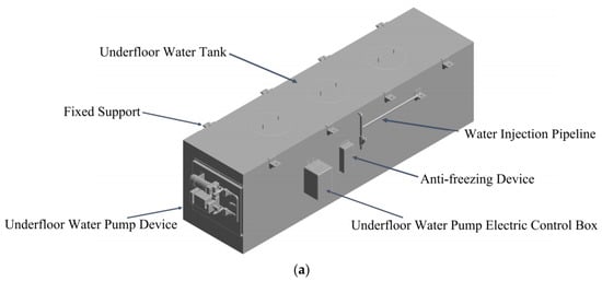
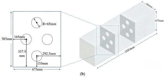
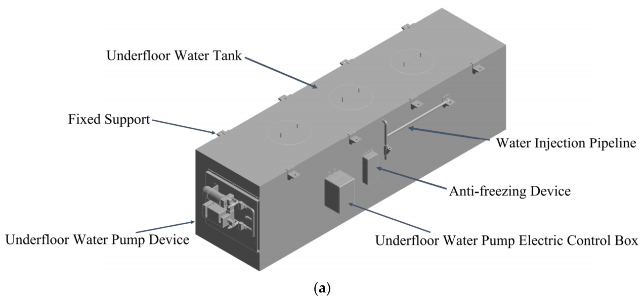
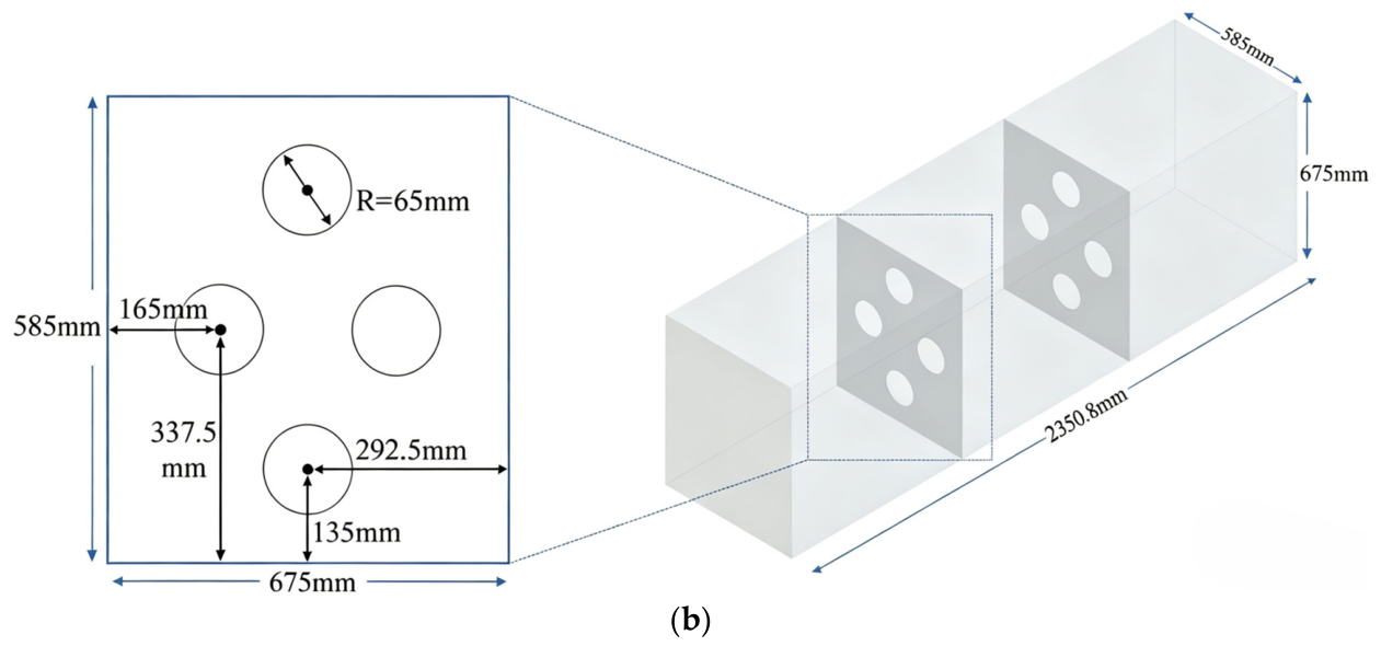
A 700 L suspended water tank of a certain type of CRH EMU was selected as the research object. The effective capacity of this tank is 3.5 times that of the 200 L suspended water tank used in other CRH models [3], resulting in significantly more pronounced internal liquid sloshing forces; therefore, this tank type was chosen for the present study. The model is shown in Figure 1. The water tank is primarily composed of the tank body, baffle, underframe water pump unit, underframe water pump electrical control box, external water system, anti-freezing device, and suspension brackets. The fluid domain inside the tank measures 2350.8 mm in length, 585 mm in width, and 675 mm in height. An internal baffle is vertically installed within the tank, with a height of 675 mm, a width of 585 mm, a thickness of 2.6 mm, and openings with a radius of 65 mm.
Figure 1.
(a) Water tank; (b) fluid domain.
The suspended water tank structure is mainly welded from Q 345 steel plates [20]; the physical property parameters of the material are listed in Table 1.
Table 1.
Material parameters.
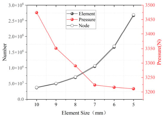
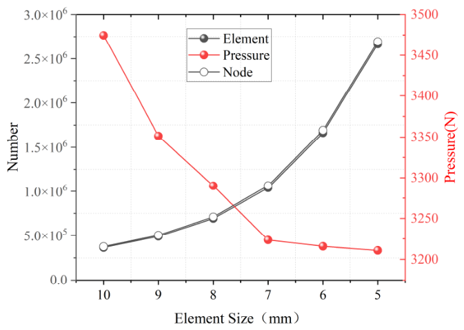
In multiphase flow numerical simulations, mesh quality is a critical factor determining simulation accuracy [26]. According to the theory of correlation between turbulent structures and mesh scales in multiphase flow fields, reducing the number of mesh nodes can shorten the computation time, but may lead to prediction deviations in key parameters such as particle concentration gradient and turbulent kinetic energy dissipation rate due to insufficient resolution of flow field details. Increasing the number of mesh nodes can improve the accuracy of flow field reconstruction, but is accompanied by a substantial increase in computational cost. To balance computational accuracy and resource consumption, a grid independence verification was conducted in this study using the pressure-holding condition of a train water tank [17]. By constructing a progressively refined unstructured tetrahedral mesh sequence, the convergence behavior of the pressure drop characteristic quantity was analyzed, and the optimal mesh scheme for subsequent numerical simulations was determined. The corresponding simulation results are shown in Figure 2 and Table 2.
Figure 2.
Grid independence verification.
Table 2.
Grid independence study.
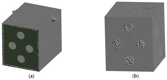
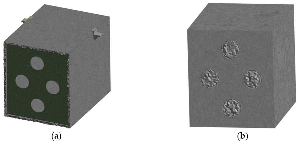
As shown in Figure 2 and Table 2, the results obtained with the 7 mm mesh have already reached convergence compared with those from finer meshes, and further mesh refinement does not significantly alter the simulation results. When the mesh size is reduced to 6 mm, the number of fluid domain cells increases substantially by 160%, leading to a significant rise in computation time. Meanwhile, as the mesh size is reduced from 10 mm to 8 mm, the pressure result changes from 3472.4 Pa to 3290.1 Pa, indicating that the error decreased by 5.66%. Balancing solution accuracy and computational cost, this study ultimately adopts a 7 mm mesh size for meshing both the solid and fluid domains of the suspended water tank. The resulting mesh model is shown in Figure 3.
Figure 3.
(a) Water tank grid; (b) fluid domain grid.
2.2. Simulation Setup and Numerical Method
2.2.1. Boundary Conditions and Load Settings
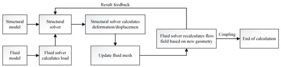
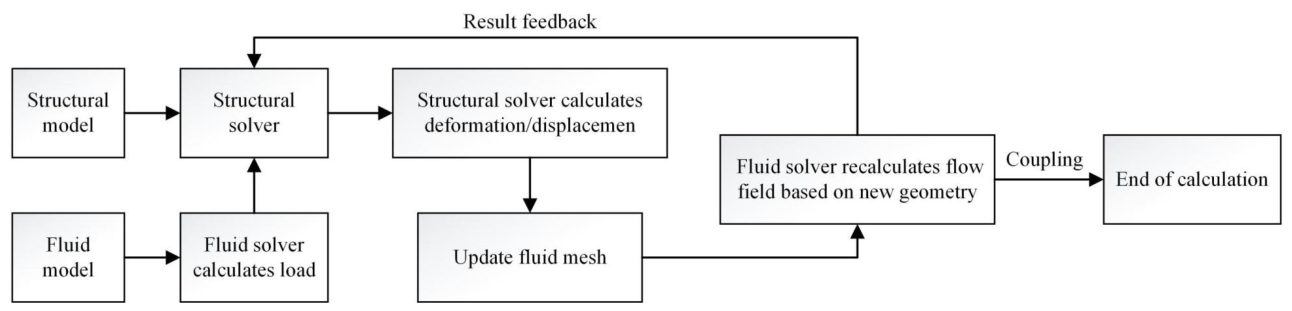
The one-way FSI method has limitations because it cannot account for the influence of solid structural deformation on the flow field. Therefore, a two-way FSI method is adopted in this study, with the procedure illustrated in Figure 4. In a two-way FSI process, the interaction forces between the fluid and the solid are in dynamic equilibrium, where the force exerted by the fluid on the solid and the reaction force from the solid on the fluid cancel each other out. This state of dynamic equilibrium varies with time and space, which is the underlying reason for the high complexity of fluid–solid interaction. The interaction between the water tank baffle and the liquid during operation constitutes a typical FSI model. Compared with the one-way FSI approach, the two-way FSI method allows for a more detailed investigation of the interaction between the tank body and the internal liquid.
Figure 4.
Flowchart of two-way fluid–structure interaction.
As shown in Table 3, the deviation for the output is below 0.3%, respectively, which confirms the accuracy of the chosen step size. Since halving the time step only marginally improves accuracy but nearly doubles the computational cost, 6 × 10⁻⁴ s is adopted for all subsequent simulations. The coupling time step is set to 6 × 10⁻⁴ s, with the number of iterations per coupling step constrained to a minimum of 5 and a maximum of 10. Load and displacement data are transferred and applied following a linearly ramped pattern. The water tank is discretized with shell elements, whereas the remaining components are modeled using solid elements. Kinematic compatibility between the two element types is enforced via an MPC (multi-point constraint) contact algorithm. In the fluid field, the SIMPLEC algorithm is employed to handle velocity–pressure coupling. The convective terms in the momentum equation are discretized using a second-order upwind scheme, the diffusive terms are treated with the QUICK scheme, and the temporal terms are solved with a second-order implicit high-resolution scheme. Within each coupling iteration cycle, the flow field undergoes 10 inner iterations, and the convergence residual threshold is set to 10−4 to balance computational accuracy and numerical stability. For the structural analysis, geometric nonlinearity is activated, and a line search method is introduced to improve the iterative convergence behavior and enhance solution robustness.
Table 3.
Verification of time-step convergence.
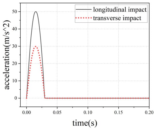
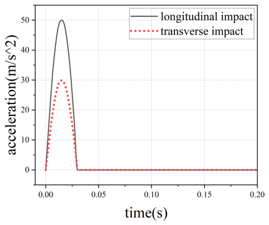
Given the time-varying flow characteristics of the incompressible fluid inside the water tank, a pressure-based solver is employed for the fluid simulation to establish an unsteady model, with the gravitational acceleration set to 9.8 m/s2. Considering the presence of two immiscible gas–liquid phases within the tank, the volume of fluid (VOF) model is adopted to capture the gas–liquid interface. The initial volume fraction of the liquid phase is set to 1, and that of the gas phase is set to 0. The densities of water and air are 998.2 kg/m3 and 1.2 kg/m3, respectively; their dynamic viscosities are 1 × 10⁻³ kg/(m·s) and 1.8 × 10⁻⁵ kg/(m·s), respectively; and the reference pressure is 101,325 Pa. The baffle and tank walls are set as no-slip walls, and the holes on the baffle as well as the upstream and downstream connecting regions of the tank are defined as fluid continuous flow regions to simulate the actual flow path. The test condition adopts the shock load specified in the shock and vibration tests for railway locomotive and rolling stock equipment [4], i.e., a sinusoidal half-sine shock function with a peak value of 30 m/s2 or 50 m/s2 applied in both the longitudinal and lateral directions, as shown in Figure 5.
Figure 5.
Shock load acceleration curve.
2.2.2. CFD Computational Method
The Navier–Stokes continuity and momentum equations, which form the theoretical foundation of CFD solvers [27], are as follows:
where ui mean velocity component in the i-th coordinate direction (i = 1, 2, 3 for x, y, z), uj mean velocity component in the j-th coordinate direction, xi, xj are spatial coordinates, t is time, ρ is the fluid density, p is static pressure, μ is molecular dynamic viscosity, uj’ is fluctuating velocity component in the j-direction, ui’ is fluctuating velocity component in the i-direction, is the Reynolds stress tensor, is the Reynolds stress term representing the additional turbulent stress; it requires closure via a turbulence model.
To simulate the irregular and unsteady forces exerted on the inner walls by liquid sloshing inside the water tank, the realizable k-ε turbulence model was adopted in this study. This model was selected over alternative turbulence models (e.g., standard k-ε, RNG k-ε, and SST k-ω) for the following reasons: (1) it provides superior performance for flows involving boundary layer separation, strong pressure gradients, and complex strain rates—conditions that are prevalent in liquid sloshing inside the water tank; (2) compared with the standard k-ε model, the realizable variant enforces the realizability of the normal Reynolds stresses, ensuring more accurate predictions of mean flow characteristics in flows with high strain rates; and (3) compared with the RNG k-ε model, it offers better computational efficiency while maintaining comparable accuracy for the present application [26].
The transport equations for the turbulent kinetic energy and turbulent dissipation rate are as follows:
where ρ is the fluid density, ui are the velocity components, μ is the molecular dynamic viscosity, and μt is the turbulent viscosity, defined as μt = ρCμk2/ε with Cμ being a model coefficient. The term Gk represents the generation of turbulent kinetic energy due to mean velocity gradients, while Gb accounts for buoyancy-induced production; YM is the contribution of fluctuating dilatation in compressible turbulence to the overall dissipation rate. The constants σk and σε are the turbulent Prandtl numbers for k and ε, respectively. The parameter S in the production term of the ε-equation is the modulus of the mean strain-rate tensor, defined as S= (2SijSij)0.5, where Sij = 0.5(∂ui/∂xj + ∂uj/∂xi). The model constants C1, C2, C1ε, and C3ε are assigned standard values (e.g., C1 = max(0.43, η/(η + 5)), η = Sk/ε, C2 = 1.9, C1ε = 1.44, C3ε = tanh∣v/u∣ for buoyant flows). Finally, Sk and Sε denote user-defined source terms, which are set to zero in the present study.
For the near-wall region, the standard wall function approach is employed, which is consistent with the high-Reynolds-number formulation of the realizable k-ε model. The first-layer mesh adjacent to the baffle and tank walls is generated to ensure that the dimensionless wall distance y +falls within the range of 30 to 300.
2.3. An Improved MOPSO Algorithm
The multi-objective particle swarm optimization (MOPSO) algorithm is an intelligent optimization algorithm established by simulating the foraging behavior of bird flocks in nature. This algorithm offers advantages such as a simple concept, few parameters, and fast convergence; however, its susceptibility to falling into local optima is also a prominent drawback, which can severely impair its ability to find the global optimal solution. In each iteration, the particle velocity and position are updated as follows:
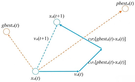
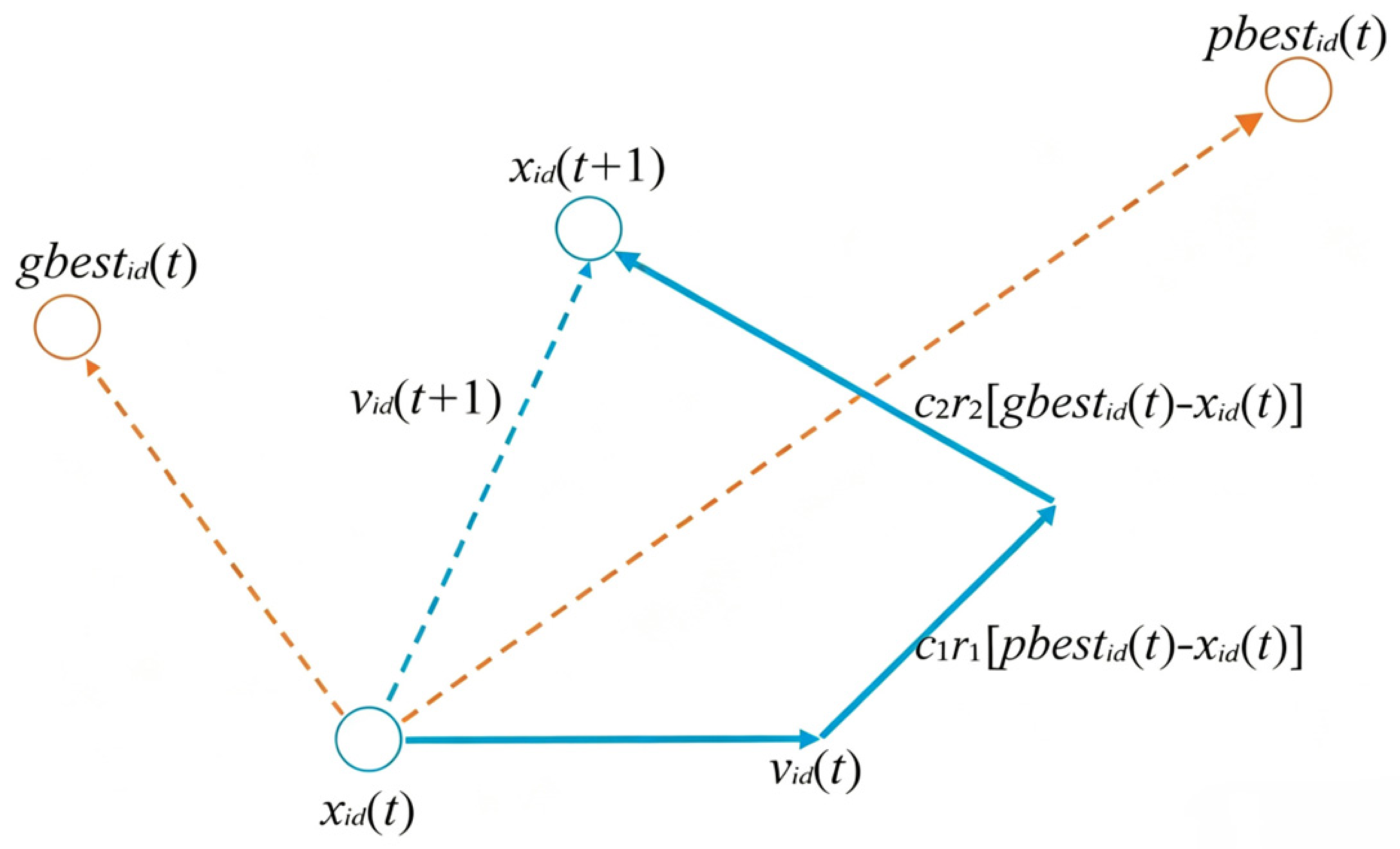
where N is the number of particles in the population; pbestid(t) and gbestid(t) are the individual best position and the global best position, respectively; n is the dimensionality of the input design decision variables; νid(t) and xid(t) are the d-th dimensional components of the velocity vector and position vector of the i-th particle after the t-th iteration, respectively; c1 and c2 are learning factors, typically set to the constant 2; and r1 and r2 are random numbers uniformly distributed between 0 and 1.
Figure 6 shows a schematic diagram of the particle update path, where the learning factors c1 and c2 adjust the step size of the particle flying towards pbest and gbest, respectively.
Figure 6.
Schematic diagram of particle update path.
In the lightweight design of high-speed train water tank baffles, the standard MOPSO faces problems such as susceptibility to local optima, simplistic constraint handling, and premature convergence caused by single-peak dominance. To address these issues, this paper proposes an IMOPSO. The specific improvements are as follows:
(1) Logistic chaotic mapping is introduced for population initialization. The iterative formula of the logistic map is:
Chaotic initialization enables particles to achieve better ergodicity and more uniform distribution in the decision space, preventing multiple particles from clustering in the same region, thereby enhancing initial diversity and global search capability.
(2) An adaptive parameter strategy based on population crowding degree is introduced. The inertia weight ω is dynamically adjusted with iterations:
where t is the current iteration number, and Tmax is the maximum number of iterations. Meanwhile, the learning factors are dynamically adjusted according to the population crowding degree: when the crowding degree is high, c1 is increased to enhance exploration; when the crowding degree is low, c2 is increased to accelerate convergence.
(3) A dynamic mutation operation is introduced. In each iteration, a certain number of particles are mutated with a probability pm:
The mutation probability is relatively high in the early iterations, which helps enhance exploration. In the later iterations, the mutation probability is lower to ensure convergence. The mutation method adopts a Gaussian–Cauchy hybrid mutation: the Cauchy mutation has a larger jump step size, which helps escape local optima; the Gaussian mutation has a smaller local search step size, which facilitates fine-grained search.
2.4. Operating Condition Design
The optimization of baffle parameters needs to be carried out after the optimal number of internal baffles in the water tank has been determined. To identify the optimal number of baffles, it is necessary to select the operating condition under which the liquid sloshing pressure inside the tank reaches its maximum under impact loading. After the optimal number of baffles is established, a surrogate model is built to conduct a lightweight parameter study of the baffles. The specific definition of working conditions and settings, as well as the baffle parameter selection criteria, are detailed as follows:
(1) During train operation, the amount of stored liquid in the water tank gradually decreases with usage, leading to corresponding changes in the loading effect of the liquid on the tank structure. The fully filled state of the water tank is defined as a 100% fill ratio, and other fill levels are defined accordingly. CFD numerical calculations were performed using Fluent 2024 R1 Student software to analyze the free surface evolution behavior and the pressure distribution characteristics on the tank walls during liquid sloshing at five fill ratios: 20%, 40%, 60%, 80%, and 100%. The fill ratio yielding the maximum sloshing impact pressure was selected as the test condition to investigate the relationship between the number of baffles and the tank stress, and thereby determine the optimal number of baffles to be installed inside the tank.
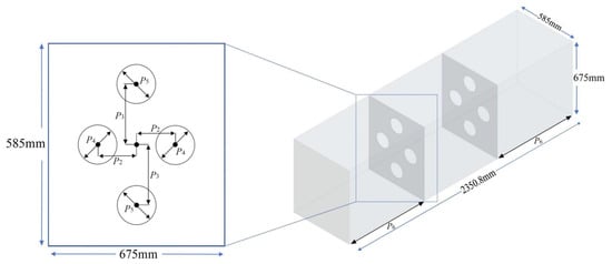
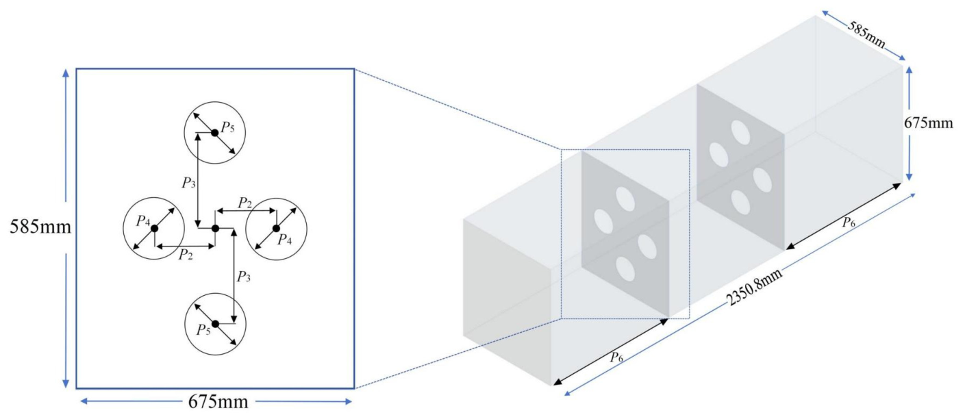
(2) Once the optimal number of baffles is determined, the geometric parameters of a single baffle of the high-speed train water tank need to be optimized. Considering the structural characteristics of the baffle, the fluid–structure interaction behavior, the manufacturing process, and the installation requirements for the train, six geometric parameters were selected as design variables: baffle thickness P1, hole spacing P2 and P3, hole radius P4 and P5, and baffle spacing P6. The baffle thickness directly determines the structural mass, stiffness, and natural frequency, and is thus the primary controlling parameter. The hole radius serve mainly to reduce weight and alter the liquid flow characteristics, while the hole spacings regulate the load transfer path and stress distribution. The baffle spacing solely adjusts the relative position between the two baffles.
The specific locations of the selected design variables are shown in Figure 7. The value ranges of the design variables are determined in accordance with the requirements of Water Supply Equipment for Railway Passenger Cars and EMUs [28], and the specific parameters are listed in Table 4. By considering the dimensions of the original vehicle model and the internal assembly space of the water tank, a three-level value range is defined for each parameter. This not only ensures structural strength and manufacturing feasibility but also allows a comprehensive investigation of the influence of parameter variations on the baffle mass, water tank stress, deformation, and the first-order natural frequency around the prototype dimensions.
Figure 7.
Selection of baffle variables.
Table 4.
Value ranges of each variable.
3. Determination of the Number of Baffles and Optimization of Baffle Parameters
3.1. Determination of Baffle Number
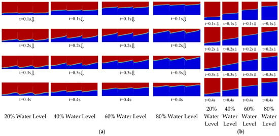
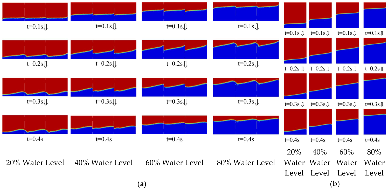
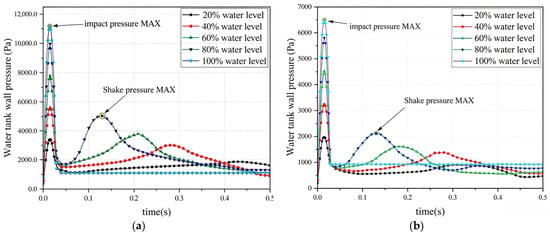
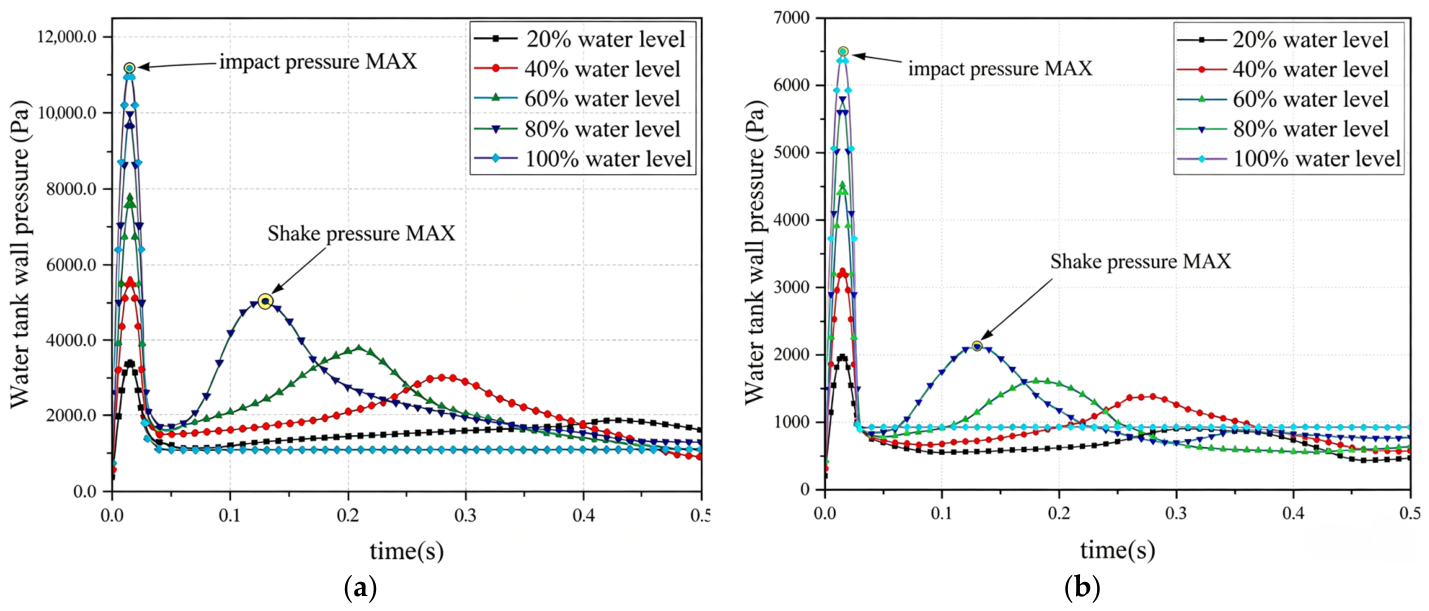
To determine the optimal number of baffles inside the water tank, it is first necessary to identify the operating condition under which the peak liquid sloshing pressure inside the tank reaches its maximum under impact loading. Figure 8 and Figure 9 shows the pressure distribution characteristics on the tank wall during liquid sloshing at five fill ratios: 20%, 40%, 60%, 80%, and 100%.
Figure 8.
(a) Schematic diagram of liquid surface evolution under longitudinal impact. (b) Schematic diagram of liquid surface evolution under transverse impact. Arrow: time direction.
Figure 9.
(a) Time-history curves of inner wall pressure of water tank under longitudinal impact. (b) Time-history curves of inner wall pressure of water tank under transverse impact.
It can be seen from the simulation results in Figure 8 and Figure 9 that the period from 0 to 0.03 s is the shock pressure application stage. The shock induces inertial motion of the liquid, causing the sloshing pressure on the inner wall of the water tank to rise rapidly; after 0.015 s, the pressure on the inner wall begins to decrease significantly. The period from 0.03 s to 0.5 s is the liquid inertial sloshing stage. After the shock ends, the liquid does not stabilize quickly but continues to exhibit a fluctuating state, indicating that the liquid has a residual motion effect after the shock. The tank fill level is positively correlated with the peak pressure on the inner wall and negatively correlated with the time at which the peak occurs. The peak shock pressure appears under the full liquid (100%) condition; when the fill level is 80%, the peak pressure during the sloshing stage reaches its highest, significantly exceeding that under other fill level conditions. Moreover, the pressure fluctuation lasts longer after the shock ends, and the residual liquid sloshing phenomenon is more pronounced.
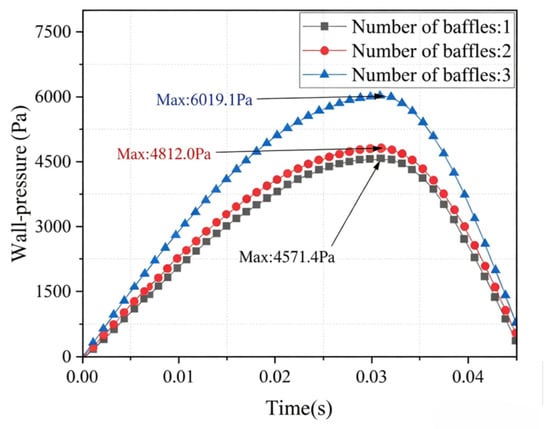
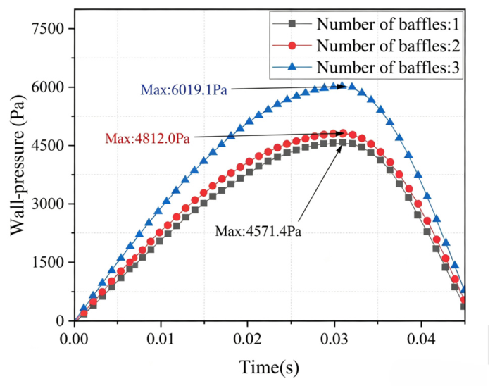
Using the longitudinal shock at 80% fill level as the test condition, the relationship between the number of baffles and the tank body stress is investigated. Figure 10 shows the shock load time-history curves of the water tank with an 80% water level and different numbers of built-in baffles under longitudinal shock at the 80% fill level.
Figure 10.
Relationship between the number of baffles and the tank wall pressure.
It can be seen from Figure 10 that the number of baffles does not change the variation pattern of the shock pressure applied to the water tank. The tank wall pressure reaches its peak within 0 s to 0.032 s and then decreases rapidly. Increasing the number of baffles does not shorten the time required for the peak overshoot of the pressure, but it significantly reduces the peak overshoot value. Compared with the case of one baffle, the peak overshoot of the pressure corresponding to two baffles is reduced by nearly 17%; compared with the case of two baffles, the peak overshoot reduction corresponding to three baffles is less than 6%. Further increasing the number of baffles yields only a limited reduction in the peak overshoot of the pressure. Considering factors such as lightweighting, manufacturing feasibility, and cost-effectiveness, the design with two baffles can be regarded as the optimal scheme.
3.2. Baffle Parameter Optimization
3.2.1. Sensitivity Analysis of Baffle Parameters
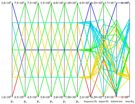
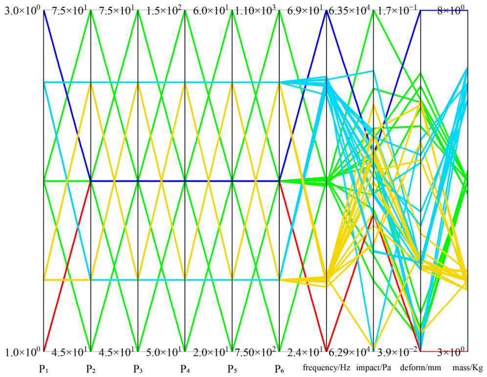
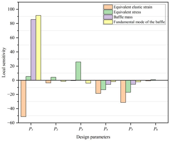
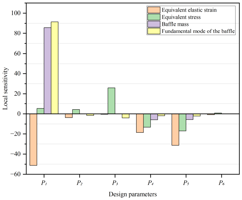
After determining the optimal number of baffles inside the water tank, the geometric parameters of a single baffle need to be optimized. Based on the six design variables selected in the simulation test condition design—baffle thickness P1, hole spacings P2 and P3, hole radius P4 and P5, and baffle spacing P6—the central composite design method was used to generate the experimental design points, and the results are shown in Table 5. The parallel coordinate Figure 11 is adopted to visualize the high-dimensional dataset of design points, identify the coupling relationship between geometric input parameters and structural dynamic responses, and screen feasible configurations satisfying multiple performance constraints simultaneously. The sensitivities of the six design variables with respect to the four objective functions, namely baffle mass, maximum water tank stress, baffle deformation, and first-order natural frequency, were calculated. Figure 12 shows the sensitivity analysis histogram. It should be noted that this approach provides global main-effect sensitivities based on the regression model, rather than Sobol total-order sensitivity indices.
Table 5.
The experimental design points.
Figure 11.
Parallel coordinates chart.
Figure 12.
Sensitivity analysis.
Since the water tank baffle is a thin-plate structure subjected to uniform fluid pressure, its mechanical characteristics are primarily influenced by factors such as bending stiffness, mass distribution, constraint conditions, and fluid load distribution. As shown in Figure 12, the baffle thickness P1 is the key parameter determining its first-order natural frequency and maximum deformation, with a sensitivity of 91.49 to the natural frequency and −51.21 to the maximum deformation, exhibiting significant positive and negative correlations, respectively. The reason is that the first-order natural frequency of a thin plate is positively correlated with bending stiffness and negatively correlated with areal density; bending stiffness is proportional to the cube of the thickness, whereas areal density is proportional to the thickness itself. The stiffness gain resulting from the increased thickness far outweighs the frequency-reducing effect of the added mass, while simultaneously substantially reducing the bending deformation under fluid pressure. In addition, P1 is strongly positively correlated with the baffle mass, with a sensitivity of 85.80, as the thickness directly determines the baffle volume and is the primary factor controlling the mass.
The hole radius P4 and P5 are secondary influencing parameters, both negatively correlated with the first-order natural frequency, baffle mass, maximum stress of the water tank, and maximum deformation, with P5 exerting a greater influence than P4. Increasing the hole radius reduces the effective bending stiffness of the baffle and decreases the amount of structural material used. For the natural frequency, the stiffness reduction effect outweighs the enhancement from mass reduction, resulting in a decrease in the natural frequency. For the maximum stress of the water tank, the enlarged hole radius weakens the baffle’s constraint on the tank wall, releasing deformation space for the wall and alleviating stress concentration. For the baffle deformation, the reduction in load-bearing area and fluid load exceeds the deformation-increasing effect of localized stiffness weakening; consequently, the final deformation decreases as the hole radius increases.
The hole spacings P2 and P3 have an overall weak influence on the various indicators, only demonstrating a notable positive effect on the maximum stress of the water tank. Among them, the vertical hole spacing P3 has a sensitivity of 25.87, making it the dominant factor affecting the maximum stress of the water tank. The hole spacing alters the load transfer path, increases the support span of the tank wall, and intensifies bending deformation and stress concentration. Since the vertical direction is the primary deformation direction of the tank wall, the effect is more pronounced in this direction. Meanwhile, as the hole spacing only adjusts the positions of the holes without changing the total opening volume, it has essentially no effect on the baffle mass, natural frequency, or deformation. The baffle spacing P6 shows extremely low sensitivity to all indicators, having almost no influence on the mass and natural frequency, and its effect on deformation and water tank stress is far smaller than that of the other parameters. This is because it only changes the relative position without altering the stiffness, mass, or volume of the baffle itself, nor does it substantially change the flow field loads or constraint states, thus exhibiting no significant regulating effect.
In summary, in subsequent experiments, P6 can be fixed at its baseline value to streamline the experimental parameters and effectively improve the speed and efficiency of the simulation calculations. A full Sobol analysis would be required for exact variance decomposition, which is beyond the scope of the present work but does not affect the validity of our factor-fixing strategy for engineering optimization.
3.2.2. Construction of Response Surface
To investigate the influence of baffle thickness P1, hole spacings P2 and P3, and hole radius P4 and P5 on baffle mass, maximum water tank stress, baffle deformation, and first-order natural frequency, the response surface methodology was employed to calculate the structural response values. By fitting the relationship between parameters and responses using basis functions, an explicit response surface model y = f(x) was constructed to approximate the complex implicit relationship between structural parameters and responses. Replacing the physical or finite element model with the response surface model for parameter prediction can significantly reduce the computational cost while maintaining high accuracy, and thus it is widely applied in many fields [29].
In engineering, response surface models are often determined based on experience, and multiple regression fitting is commonly used. When the functional relationship is simple, a first-order polynomial can be adopted; if the interaction effects among parameters need to be considered, a quadratic polynomial is usually selected. The first-order and quadratic polynomial models of the response surface are as follows:
where y is the response value with n variables; β0 is the constant term; βi are the linear coefficients; βij are the interaction term coefficients; βii are the quadratic term coefficients; and xi, xj are the independent variables.
After the functional expression is obtained through multiple regression fitting, analysis of variance should be performed on the model to verify its goodness of fit.
The overall variation in the design of experiment values can be characterized by the total sum of squares SST, denoted as St, with the expression as follows:
where y is the arithmetic mean of the experimental values; Sr is the regression sum of squares, reflecting the variation in the response value y caused by changes in the independent variables x; and Se is the residual sum of squares, representing the random error. Their expressions are as follows:
After obtaining the regression sum of squares and the residual sum of squares, combining the two yields the multiple correlation coefficient R, which is commonly used in multiple regression to evaluate the goodness of fit of the model. Its expression is as follows:
The closer the value of R is to 1, the higher the goodness of fit of the response surface; conversely, the farther it is from 1, the poorer the accuracy.
Response surface fitting equations were constructed using the data from the experimental design points generated by the central composite design method, yielding the response surface fitting equation Y1 for the baffle mass, Y2 for the water tank stress, Y3 for the first-order natural frequency, and Y4 for the baffle deformation. Here, X1 represents P1, X2 represents P2, X3 represents P3, X4 represents P4, and X5 represents P5. The specific parameters are listed in Table 6.
Table 6.
Table of equation coefficients.
Analysis of variance was performed on the quadratic response surface models for baffle mass, water tank stress, first-order natural frequency, and baffle deformation, with the results presented in Table 7. The p-values of all four models were found to be less than 0.0001, indicating that the models were highly significant overall. The p-values of the lack-of-fit terms were all greater than 0.05, suggesting no significant lack of fit and demonstrating good fitting accuracy and predictive reliability. For each response, most of the linear terms and interaction terms were highly significant factors. Among the quadratic terms, only those in the water tank stress and first-order natural frequency models were significant; the quadratic effects in the baffle mass and baffle deformation models were not significant. Specifically, X1 contributed extremely significantly to baffle mass, first-order natural frequency, and baffle deformation, acting as the dominant factor. X2 contributed extremely significantly to water tank stress, serving as the core influencing factor. X4 and X5 had significant overall effects on each response, whereas X2 and X3 had no significant influence on baffle mass and baffle deformation. The study indicates that the interactions among factors cannot be ignored, and the established models can be effectively used for the trend analysis of the target responses and parameter optimization. The R2, Adjusted R2, RMSE computed from the 45 design points used to build the response surface; PRESS, Predicted R2, computed by internal cross-validation. PRESS and Predicted-R2 values for each response are summarized in Table 7. Generally, low PRESS values and Predicted-R2 close to unity demonstrate the robust internal predictive performance of the quadratic surrogate models. Specifically for Fimpact, although the PRESS value is numerically larger (10,550) due to the higher magnitude of the response variable, the model maintains a high predictive capability with an R2pred of 0.886. Crucially, the negligible difference between the fitting R2 (0.892) and R2pred confirms that this PRESS value does not indicate overfitting. Instead, it reflects a statistically significant model that remains practically adequate and reliable for prediction within the experimental domain.
Table 7.
Analysis of variance table.
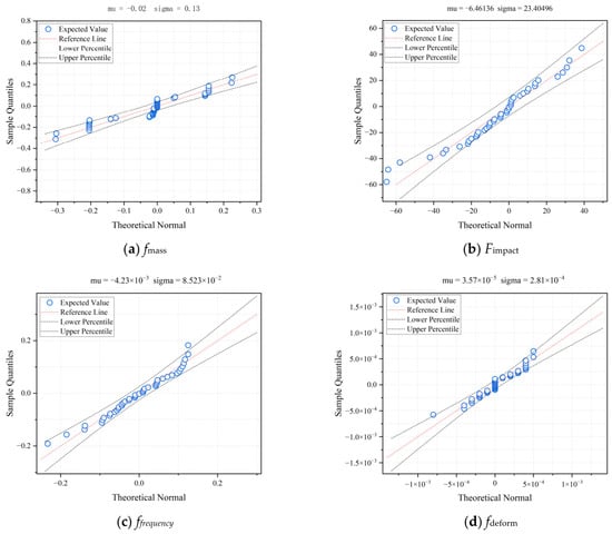
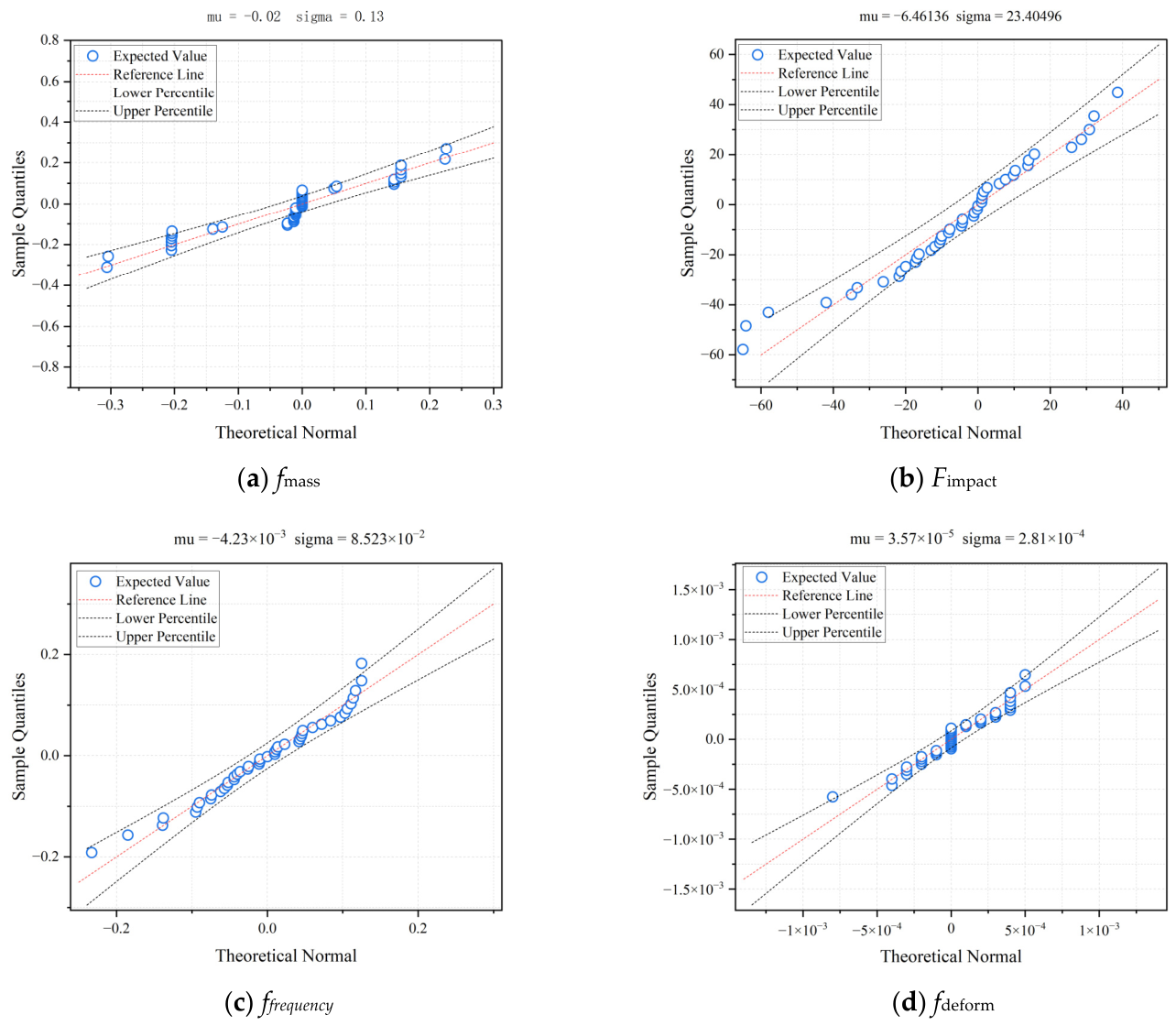
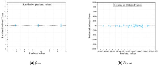
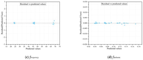
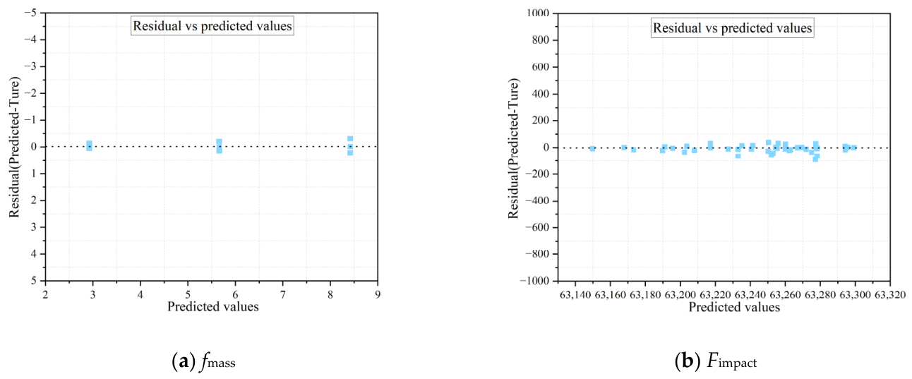
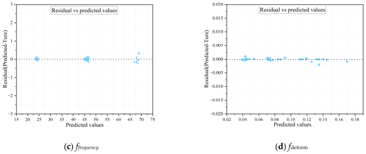
Figure 13 and Figure 14 present residual diagnostics for the response surface models. In Figure 13, the Q-Q plots show that residuals for all four responses closely follow the diagonal reference line, confirming approximate normality. In Figure 14, residuals scatter uniformly within a constant-width band across the predicted range, with no funneling, demonstrating homoscedasticity. These results validate the statistical assumptions of normality and equal variance.
Figure 13.
Normal probability (Q-Q) plot.
Figure 14.
Homoscedasticity test.
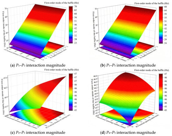
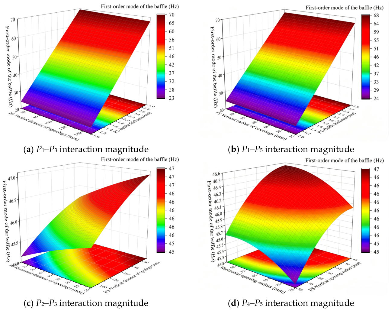
Figure 15 presents the response surface model plots between each design variable and the first-order natural frequency of the baffle, including four cases: P1 with P3, P1 with P5, P2 with P3, and P4 with P5. From the linear term coefficients of the first-order natural frequency Y3 in the response surface equation, it can be seen that the main effect coefficient of P1 is +3.21 Hz/mm with p < 0.001, indicating that for every 0.1 mm increase in thickness, the natural frequency increases by an average of 0.321 Hz, showing a significant positive correlation. The linear term coefficients of P2, P3, P4, and P5 are −0.08 Hz/mm, +0.05 Hz/mm, −0.12 Hz/mm, and +0.09 Hz/mm, respectively, with absolute values all less than 0.15 Hz/mm, which are only 2.5% to 4.7% of the P1 coefficient. Regarding the interaction terms, the interaction coefficients of P1P3 and P1P5 are +0.02 Hz/mm2 and −0.01 Hz/mm2, respectively, which are much smaller than the quadratic term coefficient of P12, −0.45 Hz/mm2. Further examination reveals that the interaction coefficient of P2P3 is −0.03 Hz/mm2 and that of P4P5 is +0.04 Hz/mm2. The frequency variations caused by these two interactions within a ±10% variation in their respective design spaces do not exceed ±0.02 Hz, accounting for only 6% of the variation produced by adjusting P1 within its range.
Figure 15.
Response surface model of the first-order natural frequency of the baffle.
Therefore, the design variable P1 plays a dominant role in achieving the goal of lightweighting while maintaining the first-order natural frequency without reduction. In subsequent experiments, lightweighting can be realized by adjusting P1 and simultaneously optimizing the opening parameters. The weak coupling effects of the opening parameters can be leveraged to offset the frequency loss induced by lightweighting, thereby ultimately achieving the design objective of lightweighting without reducing the first-order natural frequency below its initial value.
3.2.3. Multi-Objective Optimization of Baffle Parameters
The lightweight design of the train water tank baffle is a typical multi-objective optimization problem [30]. A multi-objective optimization problem refers to a scenario where there is more than one optimization objective, and in general, conflicts exist among the various objective functions. Therefore, the aim of solving such problems is to find “satisfactory solutions” rather than a single “optimal solution.” The solutions to a multi-objective optimization problem are not unique but form a set, which is referred to as the Pareto set. The multi-objective optimization functions for the current water tank baffle can be expressed as follows:
where x1, x2, x3 …, xn are the design variable combinations; M1, F2 and F3 represent the objective functions of the baffle mass, the water tank stress, and the baffle deformation, respectively; f4 is the first-order natural frequency of the baffle, serving as a constraint condition; a1, a2, a3, …, an denote the lower bounds of the design variables, and b1, b2, b3, …, bn denote the upper bounds; n is taken as 5, indicating five design variables.
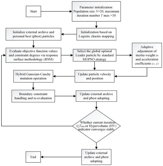
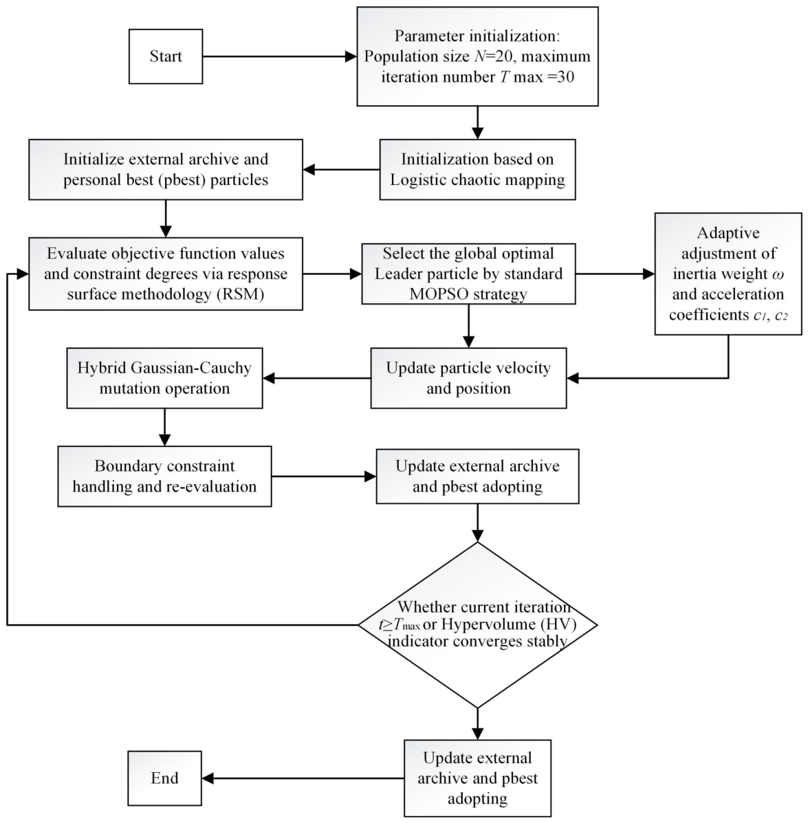
Based on the analyses in Section 3.2.1 and Section 3.2.2, the standard MOPSO exhibits the following deficiencies when addressing the lightweight design of water tank baffles: the standard MOPSO handles constraints through the constraint dominance principle, but when the feasible region is narrow, a large number of particles are discarded for violating constraints, leading to low search efficiency; the sensitivity analysis shows that the contribution of thickness P1 to the natural frequency is as high as 91.49%, and in the standard MOPSO, the global best particle (Leader) rapidly drives all particles toward the region with the maximum thickness, neglecting the synergistic compensation effect of hole diameters P4 and P5 on mass reduction; finally, the standard MOPSO lacks an effective mechanism to escape local optima—once the particle swarm converges to a local Pareto front, there is no effective mutation or perturbation mechanism. To address the above issues, this paper proposes an improved multi-objective particle swarm optimization algorithm, and its flowchart is shown in Figure 16.
Figure 16.
IMOPSO flowchart.
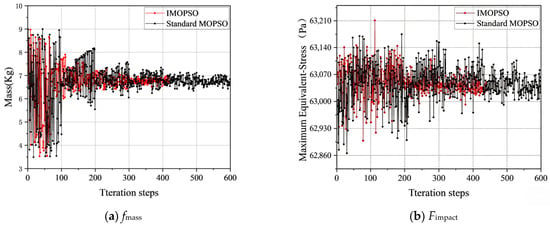
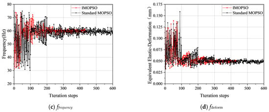
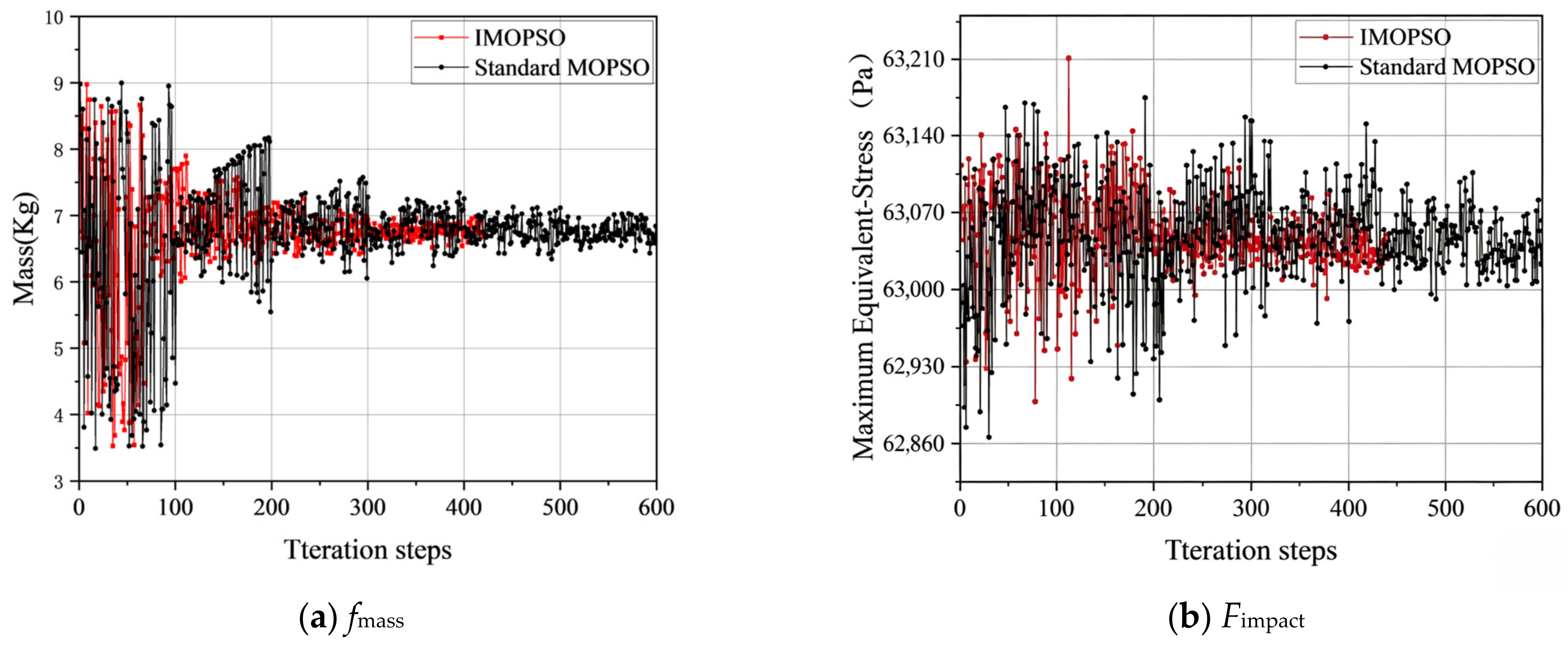
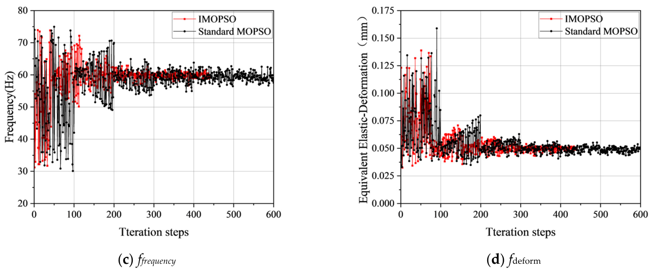
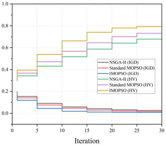
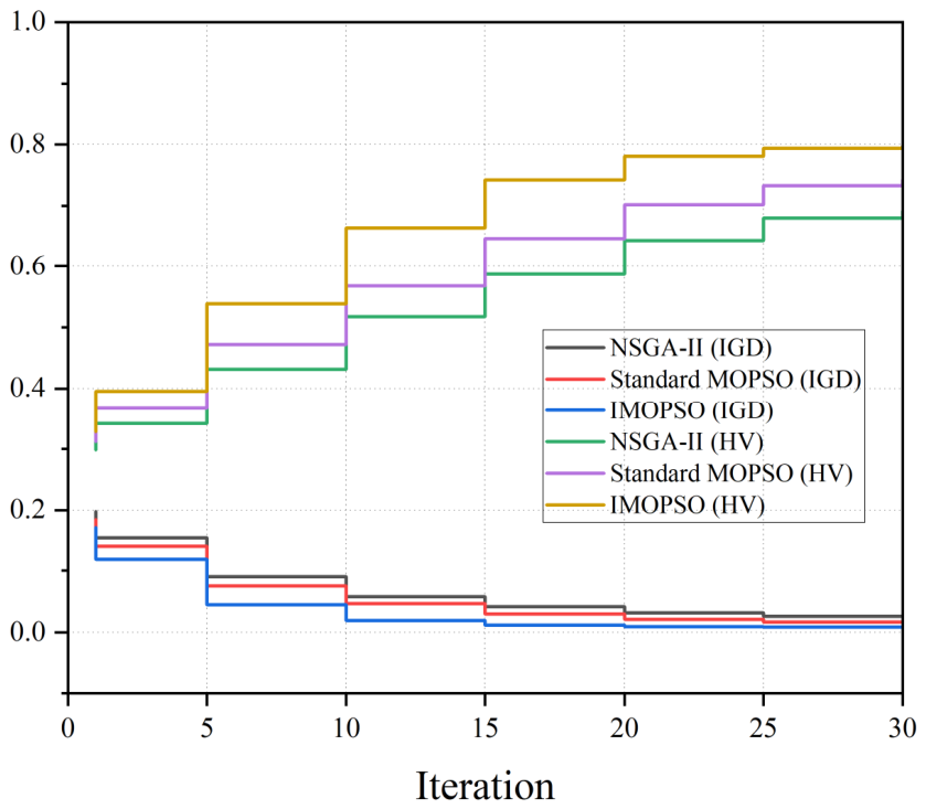
The parameter settings of the IMOPSO algorithm are as follows: population size N = 20, external archive size N~rep~ = 20, and maximum number of iterations Tmax = 30. The inertia weight adopts a linearly decreasing strategy with ω ∈ [0.4, 0.9]. The learning factors c1 and c2 are dynamically adjusted according to the population crowding degree, with initial values set to 1.5 and 2.0, respectively. Chaotic initialization employs the logistic map with the coefficient μ = 4. The dynamic mutation probability p~m~ linearly decreases from a maximum of 0.30 to 0.05, and the mutation operator adopts a Gaussian–Cauchy hybrid strategy, in which the scaling factor of the Cauchy mutation is set to 0.3 times the range of the design variables to enhance global exploration capability. The termination condition adopts a dual criterion: the algorithm terminates when the maximum number of iterations of 30 is reached, or when the change in the hypervolume (HV) over five consecutive generations is less than 1 × 10⁻⁴. Compared with the standard particle swarm optimization algorithm, the improved multi-objective particle swarm optimization (IMOPSO) algorithm exhibits significantly improved convergence efficiency and stability. The convergence trend is shown in Figure 17.
Figure 17.
Convergence curve of the iterative process.
As shown in Figure 18 and Table 8, the comparative performance of NSGA-II, standard MOPSO, and the proposed IMOPSO is examined over thirty iterations using the mean inverted generational distance and the mean hypervolume. Mean value: average across 30 independent replicate runs; Best value: optimum single-run result among replicates; Final-iteration value: metric value obtained when algorithm terminates (either early HV-triggered stop or reaching maximum iteration).
Figure 18.
Convergence curve data points.
Table 8.
Algorithm performance statistics.
IMOPSO outperforms the other two algorithms in both metrics at every recorded step under the tested conditions. At the final iteration, its mean IGD attains a value of 0.0084, which is 53.3 percent lower than that of MOPSO at 0.018 and 65 percent lower than that of NSGA-II at 0.024. Convergence is markedly accelerated in IMOPSO; by the tenth iteration its mean IGD has already decreased to 0.025, whereas MOPSO requires twenty iterations to reach a comparable level of 0.024. This early advantage can be ascribed to the chaotic initialization and the adaptive inertia weight. In terms of mean hypervolume, IMOPSO achieves the highest final score of 0.872, exceeding MOPSO’s 0.743 by 7.4 percent and NSGA-II’s 0.692 by 15.3 percent. The mean hypervolume growth of IMOPSO is most rapid during the first ten iterations, reflecting a swift approach toward the true Pareto front. In later stages, IMOPSO maintains stable mean IGD and mean hypervolume values without the minor oscillations observed for MOPSO, implying that the dynamic mutation mechanism effectively improves local exploitation and avoids premature stagnation. Furthermore, the mean hypervolume increment of IMOPSO becomes negligible after iteration 25, with a relative change below 1 percent, so that early termination at that point does not compromise solution quality. Compared to the full thirty-iteration run of MOPSO, this saves roughly 17 percent of the computational cost while still yielding superior final results. Overall, under the adopted computational budget, parameter settings, and for the test instances examined, the three proposed strategies collectively enhance both convergence speed and solution diversity, and IMOPSO exhibits better performance than MOPSO and NSGA-II. Furthermore, Statistical comparisons using Kruskal–Wallis and Mann–Whitney U tests (Bonferroni-corrected) on the 30 independent runs confirm that IMOPSO achieves significantly better mean IGD and mean HV than both MOPSO and NSGA-II (adjusted p < 0.001, effect size r > 0.8 for all pairwise comparisons).
3.3. Selection of Optimal Baffle Parameter Scheme
After convergence, the IMOPSO algorithm obtained a total of 12 non-dominated solutions. To facilitate engineering selection, this paper selects three typical candidate solutions listed in Table 9 according to the following criteria: (1) lightweight priority—the solution with the minimum mass that satisfies the frequency constraint, i.e., Solution 1; (2) comprehensive balance—the solution closest to the geometric center of the Pareto front, i.e., Solution 2; (3) high stiffness priority—the solution with the highest first-order natural frequency, i.e., Solution 3. All three solutions are superior to the original structure, among which Solution 1 achieves the best balance between weight reduction and frequency preservation and is therefore determined as the final implementation scheme.
Table 9.
Candidate schemes.
The optimized design slightly increases the baffle thickness from 2.60 mm to 2.65 mm to preserve bending stiffness, while the substantial enlargement of hole radius from 55 mm to 74.5 mm dominates the 16.13% mass reduction. The coordinated adjustment of hole spacings further optimizes the load-transfer path and alleviates stress concentration; this synergistic strategy ultimately raises the first-order natural frequency by 0.49 Hz (by RSM) despite the mass reduction and simultaneously reduces maximum stress and deformation.
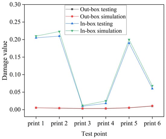
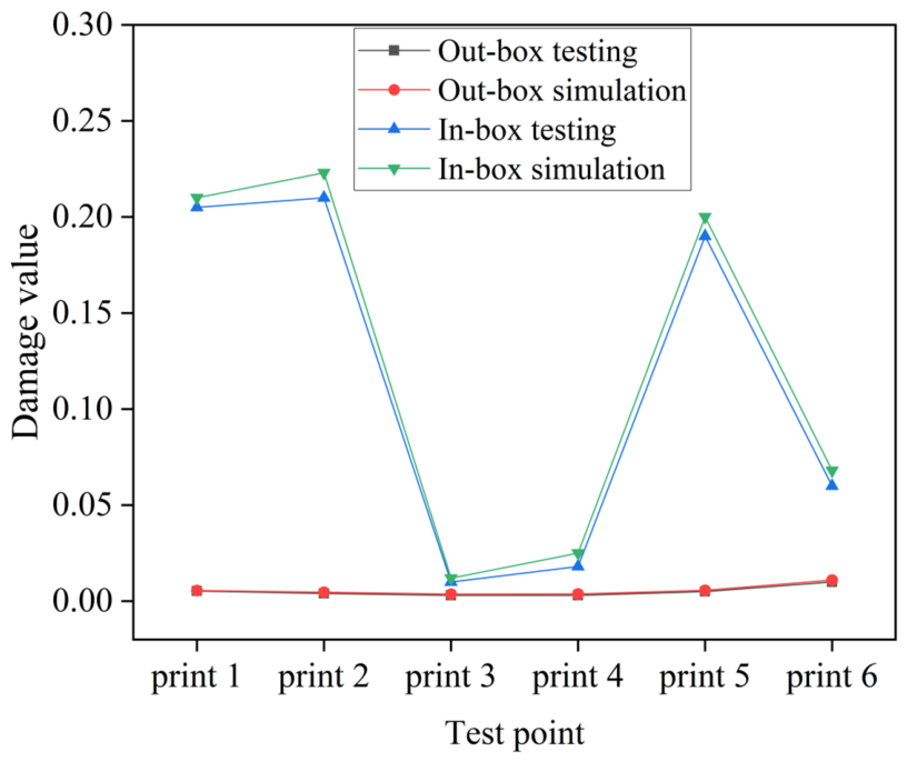
The optimized results were reproduced using finite element simulation software to verify the accuracy of the optimization method proposed in this study. To verify the accuracy of the numerical simulation method, this study performed simulation calculations of the fuel tank damage values under given loads, referencing the research object and experimental data from Liu Shangyuan [31]. Following the experimental scheme of the original literature, the same time-domain constant-amplitude sinusoidal excitation was applied to the fuel tank, with a duration of 1 s and a time step of 0.002 s, 500 steps in total. The comparison between the simulated damage values at each measuring point and the experimental results is shown in Figure 19. Owing to the unavailability of detailed parameters in the simulation model and the uncertainties introduced by simplifying assumptions and idealized boundary condition treatments, certain deviations still exist at a few points. Nevertheless, overall, the calculated damage values at each measuring point are in good agreement with the experimental results in terms of order of magnitude, with the errors of the vast majority of measuring points controlled within 4%.
Figure 19.
Comparison diagram of vertical position test inside and outside the fuel tank and simulated damage.
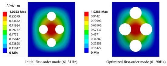
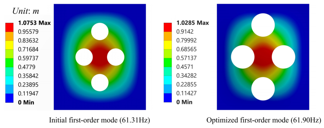
The optimal parameters obtained from the IMOPSO algorithm were input into the finite element model, and a static analysis was performed. The results predicted by the response surface model were compared with those calculated by the simulation software, as shown in Table 10. It can be observed that the relative errors of the natural frequency, stress, and deformation are only 0.16%, 0.30%, and 1.53%, respectively. The modal deformation contour plot in Figure 20 also indicates that after optimization, the overall deformation amplitude of the baffle is reduced, the stress distribution becomes more uniform, and the problem of local stiffness weakness is alleviated, fully confirming the high accuracy and reliability of the established surrogate model and the optimization algorithm.
Table 10.
Comparison of predicted and simulated results.
Figure 20.
Total deformation at the first-order natural frequency.
4. Conclusions
This study addresses natural frequency degradation in lightweight design of high-speed-train water tank baffles. A collaborative optimization framework integrating CFD two-way FSI, RSM, and an IMOPSO is proposed. The IMOPSO incorporates four enhancements—chaotic initialization, adaptive parameter adjustment, Gaussian–Cauchy hybrid mutation, and HV-based termination—to overcome standard MOPSO limitations. It achieves a mean IGD of 0.0084, best-run IGD of 0.0069 and mean HV of 0.872, outperforming MOPSO and NSGA-II. The framework simultaneously optimizes lightweight, modal retention, and impact mitigation. The following conclusions can be drawn:
(1) The fill level of the train water tank significantly affects the sloshing impact pressure and time-history characteristics. The sloshing effect is most prominent under the 80% fill condition. Adding baffles can effectively reduce the peak impact load, but the effect gradually plateaus as the number of baffles increases. Considering both performance and engineering factors, two baffles are determined as the optimal structural scheme.
(2) Based on the response surface method, quadratic polynomial surrogate models for baffle mass, maximum water tank stress, first-order natural frequency, and baffle deformation are established, with analysis of variance confirming their high significance (p < 0.0001) and good predictive reliability (lack-of-fit p > 0.05). The proposed IMOPSO algorithm is then employed to solve the multi-objective optimization model under the constraint of maintaining the first-order natural frequency. Among the three candidate schemes selected from the Pareto front, candidate Solution 1 is identified as the optimal design: baffle mass is reduced by 16.13% (by FEM), first-order natural frequency increases by 0.49 Hz (from 61.31 Hz to 61.80 Hz predicted by RSM, with FEM verification at 61.72 Hz), maximum water tank stress decreases by 288 Pa (by FEM), and baffle deformation is reduced by 7.66% (by FEM). The prediction accuracy of the surrogate model was numerically validated using finite element simulation software, showing that the maximum prediction error of the surrogate model is only 1.53%. Additionally, the numerical method’s accuracy is further validated against published fuel tank experimental data, with the vast majority of measurement points showing errors below 4% (by FEM). These results suggest the effectiveness, feasibility, and reliability of the proposed optimization framework for the studied water-tank design problem.
The proposed optimization framework achieves lightweighting while preserving the baffle’s first-order natural frequency, yet it has limitations. The RSM-based quadratic surrogate fits the design space well but is limited in nonlinear extrapolation and depends on experimental point selection. The IMOPSO algorithm outperforms standard MOPSO but requires case-specific tuning and struggles with convergence-diversity balance for complex problems. Results are specific to the studied CRH tank; other configurations need recalibration. Future work may adopt advanced surrogates, multi-condition robust optimization, topology exploration, experimental validation, adaptive parameter control, and extend the approach to other fluid-containment structures in rail, aerospace, and marine sectors. It should be noted, however, that the final optimized baffle design has not yet been validated by independent prototype testing. Such experimental validation is beyond the scope of this study and will be pursued in future work.
Author Contributions
Methodology, S.D.; Software, Y.Z.; Validation, S.D.; Formal analysis, Y.Z. and X.Z.; Investigation, Y.Z. and W.B.; Resources, Y.Z.; Data curation, X.Z.; Writing—original draft, Y.Z.; Writing—review and editing, S.D.; Visualization, W.B.; Supervision, X.Z.; Project administration, S.D.; Funding acquisition, S.D. All authors have read and agreed to the published version of the manuscript.
Funding
This research received no external funding.
Data Availability Statement
The data presented in this study are available on request from the corresponding author.
Acknowledgments
During the preparation of this manuscript, the authors used DeepSeek V3 for data analysis assistance and English language polishing. The authors have reviewed and edited the output and take full responsibility for the content of this publication.
Conflicts of Interest
The authors declare no conflicts of interest.
References
- Lei, Z.; Xu, S.; Chen, J.; Li, P.; Yu, S.; Wang, C. Research Progress in Lightweight Design of Train Body. J. Mech. Eng. 2023, 59, 177–196. [Google Scholar] [CrossRef] [Scilit]
- Li, T.; Peng, Y.; Qiao, Y.; Zhu, W.; Zhang, J.; Wang, K.; Xie, G.; Zhang, H. Experimental study on crashworthiness and lightweight of cutting-type energy-absorbing structure of magnesium alloy for trains. Eng. Struct. 2024, 301, 117287. [Google Scholar] [CrossRef] [Scilit]
- Li, Y. Strength and Fatigue Life Analysis of Suspended Water Tank Structure for High-Speed Train. Master’s Thesis, Dalian Jiaotong University, Dalian, China, 2025. [Google Scholar] [CrossRef]
- Zhao, S.C.; Che, Q.W.; Li, X.K.; Yang, J.; Niu, J.Q. Fluid-structure interaction characteristics of water tank under braking condition of high-speed train and optimal design of baffle plate opening. Roll. Stock. 2026, 64, 46–54. [Google Scholar] [CrossRef]
- Liu, Y.; Lin, X.; Li, Z.; Dai, P.; Zan, H.; Cai, D.; Du, C. Design and application of carbon fiber composite material in end box of rail transit vehicles. IOP Conf. Ser. Mater. Sci. Eng. 2019, 612, 032200. [Google Scholar] [CrossRef] [Scilit]
- Gu, Z.Y.; Jiang, R.C.; Liu, D.W.; Sun, H.X. Optimization design of the control arm of CFRP-aluminum foam sandwich structure. Chin. J. Eng. 2023, 45, 446–453. [Google Scholar] [CrossRef]
- Liu, L.; Wang, J.; Tian, H.; Li, X.; Yu, H. Lightweight design of materials for rubber-tired trains. Results Eng. 2025, 27, 106067. [Google Scholar] [CrossRef] [Scilit]
- Wang, Y.; Chen, S.; Zhang, Y.; Liang, J.; Chen, J.; Liu, C.; Wang, M. A novel laser cladding AlMgZnCuErZr alloy: Material genetic design, strengthening andtoughening mechanisms. Mater. Des. 2024, 238, 112644. [Google Scholar] [CrossRef] [Scilit]
- Liu, B.; Yang, J.; Zhang, X.; Li, X. Topology Optimization and Lightweight Platform Development of Pure Electric Vehicle Frame-Type Aluminum Body Considering Crash Performance. J. Mater. Eng. Perform. 2024, 34, 1–11. [Google Scholar] [CrossRef] [Scilit]
- Lewis, G.M.; Buchanan, C.A.; Jhaveri, K.D.; Sullivan, J.L.; Kelly, J.C.; Das, S.; Taub, A.I.; Keoleian, G.A. Green Principles for Vehicle Lightweighting. Environ. Sci. Technol. 2019, 53, 4063–4077. [Google Scholar] [CrossRef] [Scilit] [PubMed]
- Qin, J.M.; Wang, S. Optimization Design of Water Tank Structure Based on Fluid Structure Coupling. Model. Simul. 2024, 13, 597–610. [Google Scholar] [CrossRef]
- Li, J.; Gao, G.; Yu, Y.; Zhuo, T.; Li, J. Experimental and numerical study on the lightweight design of load-bearing energy absorption structure for subway train. Thin-Walled Struct. 2024, 197, 111542. [Google Scholar] [CrossRef] [Scilit]
- Jin, J.-W.; Ahn, D. Development of a lightweight carbon fiber reinforced plastic water tank for fire trucks. J. Sci. Adv. Mater. Devices 2024, 9, 100697. [Google Scholar] [CrossRef] [Scilit]
- Bao, S.G.; Jiang, C.X.; Ding, J.Y. Optimization design of EMU water tank based on response surface model and multi-objective genetic algorithm. Sci. Technol. Eng. 2019, 19, 344–350. [Google Scholar] [CrossRef]
- Zhang, X. Optimization Design of Train Water Tank Structure Based on Fluid-Structure Coupling Analysis. Master’s Thesis, Shijiazhuang Tiedao University, Shijiazhuang, China, 2021. [Google Scholar] [CrossRef]
- Tokar, A.; Ostoia, D.; Negoitescu, A. Mathematical simulation of a tank used for equipping a high speed train in order to aim safe operation. In Proceedings of the EURO-Mini Conference; Vilnius Gediminas Technical University, Department of Construction Economics & Property: Vilnius, Lithuania, 2009; pp. 517–521. [Google Scholar]
- Liu, L. Strength analysis and structural optimization of water tank mounting frame for a stainless steel railway car. China High Technol. Enterp. 2016, 30, 30–31. [Google Scholar] [CrossRef]
- Wang, W.Q.; Wang, W.; Shen, C.Q.; Cui, Y.S.; Yang, F.X. Topology optimization of water tank bracket based on variable density method. Autom. Appl. 2025, 66, 206–209. [Google Scholar] [CrossRef]
- Wang, W. Structural Analysis and Optimization of a New EMU Fuel Tank. Master’s Thesis, Dalian Jiaotong University, Dalian, China, 2019. [Google Scholar] [CrossRef]
- Dong, S.; Zhao, Y.; Li, S.; Bai, W.; Shan, X. Research on Acoustic-Black-Hole-Type Baffles for Suspended Water Tanks of High-Speed Trains: Considering Vibration and Wave Suppression Characteristics. Appl. Sci. 2026, 16, 1807. [Google Scholar] [CrossRef] [Scilit]
- Cascino, A.; Meli, E.; Rindi, A. A strategy for lightweight designing of a railway vehicle car body including composite material and dynamic structural optimization. Railw. Eng. Sci. 2023, 31, 340–350. [Google Scholar] [CrossRef] [Scilit]
- Ye, Q.L.; Wang, W.L.; Wang, Z. Survey of multi-objective particle swarm optimization algorithms and their applications. J. ZheJiang Univ. (Eng. Sci.) 2024, 58, 1107–1120. [Google Scholar]
- Liu, H.W. Research on Structural Optimization Design of Electric Multiple Unit Car Body Based on Improved Particle Swarm Optimization. Master’s Thesis, Beijing Jiaotong University, Beijing, China, 2017. Available online: https://kns.cnki.net/kcms2/article/abstract?v=lHKEv291v2if4IZrsb7cksNV4JjXVxucCNjM5Sh-wsYV0O83qoTw_cayK_u8B39Rzg1l7G3qMe2lTWndtdd_cYKqEMPfZgiOqy7_-Tug3woUQMTWaANJBiFQnJqK3Fsj4y-Y-gzPbVULXVMYOJLLqq5zmJCKUR88mN9nx6rpyGWOu40naf0Ctg==&uniplatform=NZKPT&languag (accessed on 10 August 2026).
- Wang, C. Improvement of Particle Swarm Optimization and Its Application in Structural Optimization of CRH3 Electric Multiple Unit. Master’s Thesis, Beijing Jiaotong University, Beijing, China, 2018. Available online: https://kns.cnki.net/kcms2/article/abstract?v=lHKEv291v2iNvhbdgju65JtKJJwF66-9OrH7rwLUgcL_eKnvlFi24szKY6zJ6DFJGxM8RKDNtltWYir8xH93mxrmEv_KcYREmg2k6M0DFUVkpaGTHwbG7_EfHdDZlbrw1BUF11_Y2tGWS0Yc-LmMp-ryhI4VWobhUr1qItzz_ocz9o8paLMFIQ==&uniplatform=NZKPT&language (accessed on 10 August 2026).
- Kang, E.; Lin, M. Multi-objective optimization of active disturbance rejection control parameters for PMSM based on improved MOPSO. J. Phys. Conf. Ser. 2025, 3065, 012011. [Google Scholar] [CrossRef] [Scilit]
- Li, S.; Dong, S.; Li, Y.; Zhou, L. Numerical simulation and theoretical study on the impact of wind-sand flow of high-speed trains in long tunnel space. Sci. Rep. 2024, 14, 13687. [Google Scholar] [CrossRef] [Scilit] [PubMed]
- Urbanowicz, K.; Bergant, A.; Stosiak, M.; Deptuła, A.; Karpenko, M. Navier-Stokes Solutions for Accelerating Pipe Flow—A Review of Analytical Models. Energies 2023, 16, 1407. [Google Scholar] [CrossRef] [Scilit]
- Jianhui, J.; Zhenxuan, S.; Yuanbin, Z.; Zhen, H.; Zefeng, W. Review of the structural strength standard system for underfloor equipment of high-speed trains in China. Railw. Roll. Stock. 2026, 64, 1–11. [Google Scholar] [CrossRef]
- Zhou, W.; Yan, J.; Bai, J.; Hou, F.; Lyu, Y. An Effective Dust Collection Tray and Its Performance Optimized for Compact Sweepers Based on CFD-RSM Method. Appl. Sci. 2026, 16, 3549. [Google Scholar] [CrossRef] [Scilit]
- Wang, J.; Huang, W.; Liu, C.; Dong, G.; Yuan, F.; Yang, Y.; Ma, Y. Multi-Objective Optimization for the Time-Dependent Green Vehicle Routing Problem with Time Windows. Sustainability 2026, 18, 5319. [Google Scholar] [CrossRef] [Scilit]
- Liu, S.Y. Research on Stress Test and Life Assessment of Locomotive Fuel Tank. Master’s Thesis, Southwest Jiaotong University, Chengdu, China, 2020. [Google Scholar] [CrossRef]

Disclaimer/Publisher’s Note: The statements, opinions and data contained in all publications are solely those of the individual author(s) and contributor(s) and not of MDPI and/or the editor(s). MDPI and/or the editor(s) disclaim responsibility for any injury to people or property resulting from any ideas, methods, instructions or products referred to in the content. |
© 2026 by the authors. Licensee MDPI, Basel, Switzerland. This article is an open access article distributed under the terms and conditions of the Creative Commons Attribution (CC BY) license.