


Abstract
Conventional hole finishing requires separate drilling and top/bottom chamfering, and excessive insert pressure can leave scratch-type marks on the hole wall. This study develops a clip-spring-based tool that performs drilling and top/bottom chamfering in a single machining cycle, with the chamfer depth passively set by equilibrium between the hole-wall reaction and the restoring force of a replaceable clip spring. A dual-angle insert–clip-spring interface produces a non-monotonic force drop followed by a low-incremental-stiffness plateau, separating high-force burr engagement from lower-force hole passage. Four insert-geometry and spring-bottom-shape combinations were analyzed by nonlinear finite element analysis, and the two embossed-bottom cases were supported by compression tests. The dual-angle/embossed case showed a 72% Force Dip, which compression testing reproduced together with the low-force plateau, and one-step machining confirmed process feasibility. The measured hole-wall roughness decreased fourfold, from Ra 1.7 μm to 0.4 μm. These results demonstrate a passive geometric route to Force Dip generation and self-equilibrating depth setting under the tested condition.
1. Introduction
Hole machining of mechanical components is conventionally carried out through a sequential process of drilling, top chamfering, and bottom chamfering. However, such a multi-stage process can reduce productivity owing to the increased processing time and the non-cutting time incurred by tool changes. Accordingly, combined machining tools capable of performing drilling and top/bottom chamfering with a single tool in a single process have been actively pursued [1,2]. During hole passage, uncontrolled insert contact can raise local wall pressure and leave surface marks [1]. In this study, these observations are treated as an application-level indicator of contact management; the primary focus is the force–displacement mechanism that governs chamfer depth and hole-passage contact.
In parallel, studies aimed at improving machining quality in both the drilling and chamfering processes have been actively conducted. In drilling, the effects of the cutting conditions and tool state on hole quality have been widely investigated: increases in the feed rate and spindle speed have been reported to increase surface defects and burr formation on the hole inner surface [3,4], and tool geometry such as the drill point angle and clearance angle has been found to directly affect the surface roughness, roundness, cylindricity, and perpendicularity of the hole [5]. Studies have also been conducted to improve the geometric and dimensional accuracy of through-holes by optimizing the drilling motion and feed strategy [6], as well as on methods for quantitatively evaluating the quality of machined holes [5,6]. In chamfering, the effects of the chamfer insert geometry and cutting conditions on the cutting force and machining quality have been analyzed: the dead metal zone formed beneath the chamfer face has been shown to govern the cutting force and tool wear [7], the built-up edge on the chamfer cutting edge has been found to affect the cutting force [8], and process and control techniques for automating the chamfering of hole edges have also been reported [9]. Although such chamfering also serves as a deburring process that removes burrs at the hole edge, performing deburring as a separate process incurs additional processing time and cost and can degrade the dimensional accuracy [10,11]; the need to integrate drilling and chamfering into a single process has therefore been continually raised.
Taken together, these studies form three streams, each of which leaves the present problem unresolved. Process-condition studies improved hole quality by optimizing feed rate, spindle speed, and drill geometry [3,4,5,6], but treated drilling and chamfering as separate operations and therefore did not remove the non-cutting time introduced by tool changes. Chamfering-process studies clarified how the insert geometry and the built-up edge govern cutting force and tool wear, and automated the chamfering of hole edges [7,8,9], yet the force delivered through the insert remained a monotonically increasing function of engagement. Combined and compliant tools reduced the number of operations and improved adaptability to positional error [1,2,10,11], but they likewise retained a monotonic restoring-force characteristic, so a single passive stroke could not simultaneously supply the high force required for burr engagement and the low contact force required during hole passage. The gap addressed in the present study is therefore not process integration in itself, but the deliberate shaping of the force–displacement characteristic so that these two conflicting requirements are separated within one passive stroke.
Recent process-characterization studies have further shown that nominal material or component properties alone may not predict performance under actual operating conditions, and that dedicated experimental methods are needed to isolate the effects of process parameters and interface behavior. Zinatlou Ajabshir et al. [12] quantified the influence of temperature and operating speed on the spreading of polymeric powders in powder bed fusion and demonstrated that conventional flowability indicators do not necessarily coincide with process-specific spreadability. Although that application concerns powder spreading rather than chamfering, the methodological point transfers directly: a component-level characteristic measured under nominal conditions is not by itself evidence of process-level behavior. This distinction motivates the approach adopted here, in which the clip-spring characteristic obtained from quasi-static component tests is treated as a mechanism-level result and is examined separately under representative machining conditions.
Focusing on this need for process integration, this study develops a clip spring-based combined machining tool capable of simultaneously performing drilling and top/bottom chamfering in a single process. The developed tool is designed to improve machining efficiency by reducing the number of processes and to contribute to higher productivity by minimizing the non-cutting time associated with tool changes.
A defining feature of the developed tool is that the chamfer depth is not prescribed by separate numerical control (NC) positioning; it is set passively by the structural equilibrium between the contact reaction force generated between the insert and the hole wall during machining and the restoring force of the nonlinear clip spring supporting the insert. Specifically, as the drill descends and the cutting edge of the chamfer insert contacts the hole edge, the hole wall exerts a reaction force that pushes the insert radially inward, causing the insert to retract and compress the clip spring located behind it. At the same time, the clip spring generates a restoring force that pushes the insert outward, and the position at which these two forces reach equilibrium defines the chamfer depth. This behavior is referred to here as passive self-equilibrating chamfer-depth setting.
In this self-equilibrating mechanism, the dominant design factor is the shape of the curve that the restoring force of the clip spring forms with respect to displacement. For a conventional monotonic spring response [1], the restoring force does not decrease after chamfer engagement; consequently, achieving both a high burr-engagement force and a low hole-passage contact force within a single passive stroke is difficult. Moreover, conventional coil-spring-embedded chamfering tools have a closed structure in which the coil is buried inside the tool body, making it very difficult to replace the spring alone without disassembling the entire tool when the spring is worn, yielded, or fatigue-fractured. This becomes a major cause of increased tool maintenance time on mass-production lines.
The thin-plate clip spring adopted here can be replaced simply by pulling it out of and inserting it into a slot on the outer circumference of the chamfer insert holder, which is also advantageous in terms of maintainability. By adopting a dual-angle structure in which the contact region where the clip spring and the chamfer insert meet is divided into two inclination angles, a non-monotonic behavior (Force Dip), in which the spring restoring force temporarily decreases over a specific displacement range, was intentionally induced.
The contribution of this study does not lie simply in integrating drilling and chamfering or in using a spring-loaded insert, both of which have already been adopted in machining practice. Rather, the novelty lies in intentionally generating a Force Dip transition followed by a quasi-zero-stiffness (QZS)-like low-incremental-stiffness plateau through the contact-state transition between the two inclined surfaces of the dual-angle insert and the replaceable thin-plate clip spring. This passive non-monotonic response separates the required force levels within a single tool motion: a high peak force engages the burr, the negative-slope transition reduces the force, and the subsequent low-force plateau limits contact pressure during hole passage.
Whereas conventional passive QZS mechanisms combine positive- and negative-stiffness branches [13,14,15], the proposed mechanism generates the desired force profile through a contact-angle transition without an additional negative-stiffness element. The resulting force sequence is applied here to a passive self-equilibrating chamfer-depth setting in a combined drilling–chamfering process.
In this study, the structural force-equilibrium mechanism formed by the dual-angle chamfer insert and the nonlinear clip spring was quantitatively modeled; the restoring force–displacement curve of the clip spring that produces the Force Dip behavior was derived through nonlinear quasi-static finite element analysis (FEA) performed using ANSYS Mechanical 2025; and the validity of the proposed mechanism was verified by quantitatively comparing the curve with compression test results.
2. Structure of the Chamfering System and the Self-Equilibrating Mechanism
2.1. Configuration of the Drilling–Chamfering Combined Tool
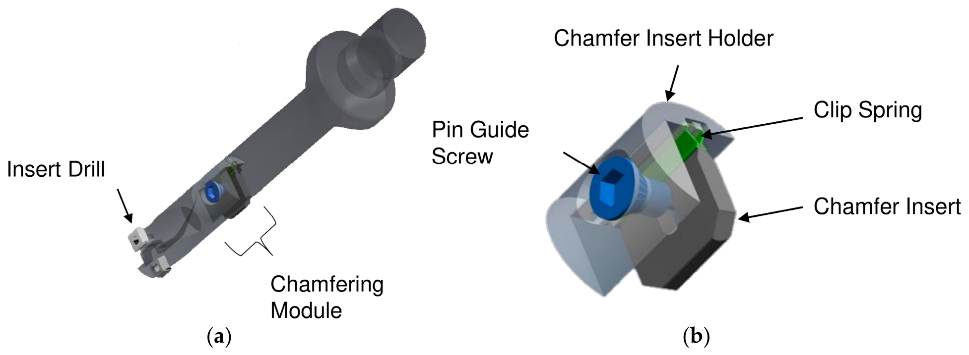
Figure 1 shows the overall configuration of the drilling–chamfering combined tool. The tool was developed to perform drilling and top/bottom chamfering of holes in a single process, and it has a structure in which the drill insert and the chamfering module are integrated within a single body [16]. The chamfering module is mounted in an open configuration on the outer circumferential surface of the drill body, and the chamfer insert is constrained by a pin guide screw so that it can slide only in the radial direction within a slot and within a limited stroke. The nonlinear clip spring supports the rear face of the insert inside the chamfer insert holder and, when the insert retracts, deforms in compression to generate a restoring force.
Figure 1.
Configuration of the drilling–chamfering combined tool: (a) overall view of the drill body; (b) cross-sectional view of the chamfering module.
2.2. Chamfering Machining Cycle and Force Flow
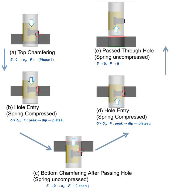
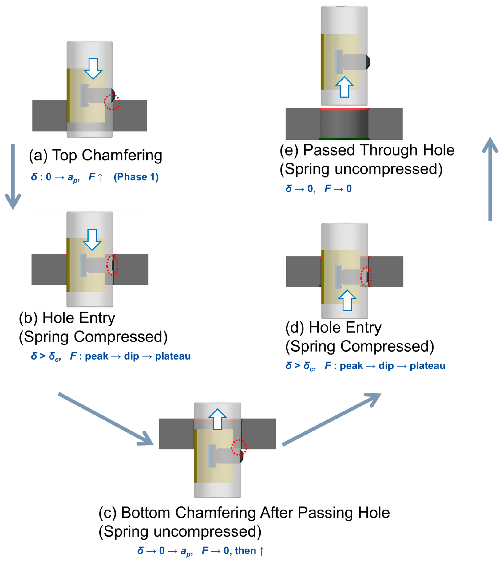
Figure 2 illustrates, stage by stage, the flow of forces acting between the chamfer insert and the clip spring during one machining cycle. The chamfering cycle following drilling consists of the following five stages.
Figure 2.
Force flow during each phase of the chamfering cycle: (a) top chamfering; (b) hole entry—spring compression; (c) bottom chamfering after passing the hole—spring extension; (d) hole re-entry on return—spring compression; (e) hole passage—spring extension. Large blue arrows indicate the progression of the machining cycle, whereas the white-filled blue arrows indicate the axial motion direction of the tool. Blue annotations indicate the qualitative trends of the insert retraction δ and the spring reaction force F at each stage, where ap is the chamfer depth and δc the critical displacement; the peak-dip-plateau sequence corresponds to the three phases of the Force Dip mechanism described in Section 2.3.
- (a)
- In the top chamfering stage, the moment the cutting edge of the chamfer insert contacts the top edge of the hole, the hole wall generates a wall reaction force acting radially inward on the insert. This reaction force pushes the insert inward along the pin guide slot and compresses the clip spring behind it. The clip spring then generates a restoring force that pushes the insert back outward, and the chamfering depth is self-determined at the equilibrium position between the reaction force and the restoring force.
- (b)
- In the hole entry stage, the drill continues to descend until the chamfer insert has fully entered the hole. The outer face of the insert remains in contact with the hole wall and is constrained radially inward, while the clip spring remains compressed. Because the insert moves while maintaining the maximum contact reaction force in this section, excessive contact pressure on the hole inner surface can cause scratches. To prevent damage to the hole inner surface, the contact force between the insert and the hole wall must be designed to be minimized.
- (c)
- In the bottom chamfering stage, the moment the chamfer insert completely passes through the bottom of the hole, the wall reaction force disappears and only the restoring force of the clip spring acts, returning the insert to its outermost position and initiating the bottom chamfering stage. Subsequently, as the drill reaches its bottom dead center and switches to upward motion, the chamfer insert re-contacts the bottom edge of the hole to perform back-chamfering, which is carried out in the same manner as the top chamfering stage.
- (d)
- In the hole re-entry stage after bottom chamfering, the drill rises again until the chamfer insert has fully entered the hole.
- (e)
- In the hole passage stage, the moment the drill continues to rise and the chamfer insert completely exits the top of the hole, the wall reaction force disappears again, and the clip spring returns to its initial state under its restoring force. One machining cycle is thereby completed, and the initial conditions for the next machining operation are restored.
This post-drilling chamfering cycle means that the chamfer depth is set passively by the structural force equilibrium internal to the machining system, not by external NC; the chamfering precision therefore depends directly on the shape of the clip spring’s restoring force–displacement curve. Accordingly, the following section describes the clip spring and chamfer insert geometries that govern this restoring-force response.
2.3. Clip Spring and Chamfer Insert
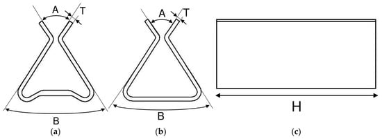
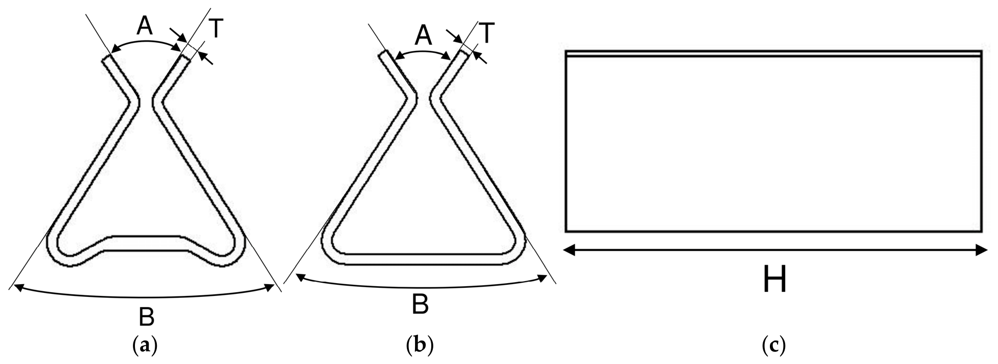
Two types of clip spring geometry and two types of chamfer insert geometry were modeled, as shown in Figure 3 and Figure 4. Analyses were then performed for the four cases obtained by combining them. Figure 3 shows the two clip spring design geometries considered in this study, namely (a) the flat-bottom shape and (b) the embossed-bottom shape. Both clip spring designs share the same four common design variables, that is, the upper angle A, the lower angle B, the thickness T, and the length H, and they differ only in the shape of their bottom region.
Figure 3.
Two clip spring designs: (a) flat-bottom; (b) embossed-bottom; (c) lateral view in the common length direction.
Figure 4.
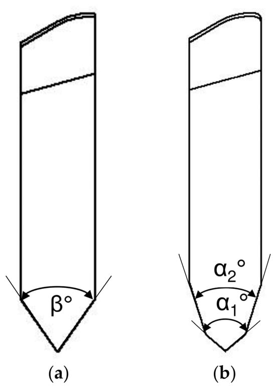
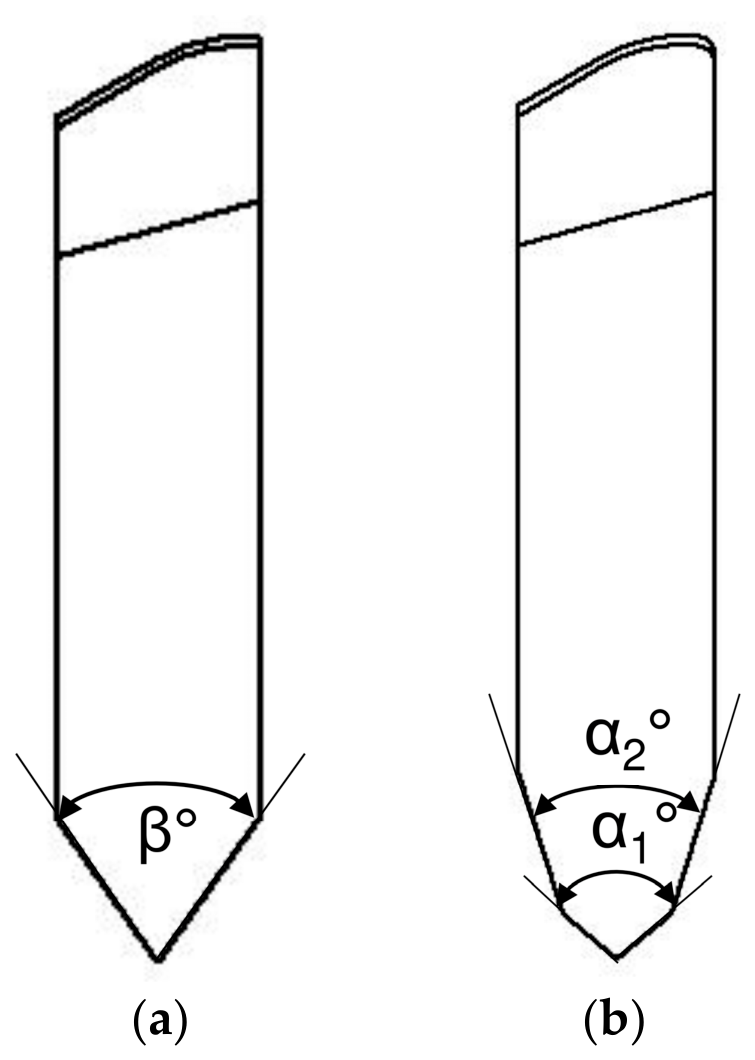
Two chamfer insert geometries: (a) single-angle—single chamfer angle β; (b) dual-angle—lower angle α1, upper angle α2.
Because the present chamfering mechanism is a structure in which contact compression occurs as the chamfer insert is gradually fitted into the contact region of the clip spring, the bottom shape of the clip spring becomes a key design factor that directly determines both the stress distribution generated during compressive deformation and the magnitude of the maximum spring reaction force. For this reason, an embossed-bottom clip spring with an added ridge for stress dispersion and stiffness enhancement (Figure 3b) and a flat-bottom clip spring without such a ridge (Figure 3a) were designed. The reaction force responses of all four insert–spring combinations were systematically compared by FEA, and the two embossed-bottom configurations (Cases 3 and 4) were further supported by compression tests.
The embossed bottom in Figure 3b is expected to disperse the contact stress both spatially and temporally and to increase the maximum spring reaction force through the additional support point provided by the ridge. In contrast, the flat bottom in Figure 3a produces a localized stress concentration at a single point on the inner side of the bend, which in turn limits the maximum spring reaction force that affects the chamfer cutting force.
Thus, the spring-bottom shape tunes the force level, whereas insert geometry determines whether a Force Dip can occur.
Figure 4 shows the two chamfer insert geometries: single-angle and dual-angle. In the single-angle insert of Figure 4a, the contact region in contact with the spring consists of a single inclination angle. In this structure, when the insert compresses the spring, the contact region moves only over the single inclined surface, so that the effective stiffness of the spring increases monotonically with increasing displacement and, consequently, a monotonically increasing restoring-force response occurs. Therefore, because the chamfer insert moves while maintaining the maximum contact reaction force during the hole entry stage after top chamfering, excessive contact pressure on the hole inner surface can cause scratches.
By contrast, the dual-angle insert of Figure 4b has a geometry in which the contact region is divided into two zones: a lower inclination α1 and an upper inclination α2. It induces the Force Dip through a transition in contact location and orientation between the chamfer insert and the clip spring. Microscopically, the contact remains a line contact over the entire displacement range; however, as the insert descends, the line-contact location moves from the α1 inclined surface, across the edge boundary between α1 and α2, to the α2 inclined surface. The associated contact normal and load-transfer direction therefore change rapidly across the transition region, causing abrupt changes in the system stiffness and required load.
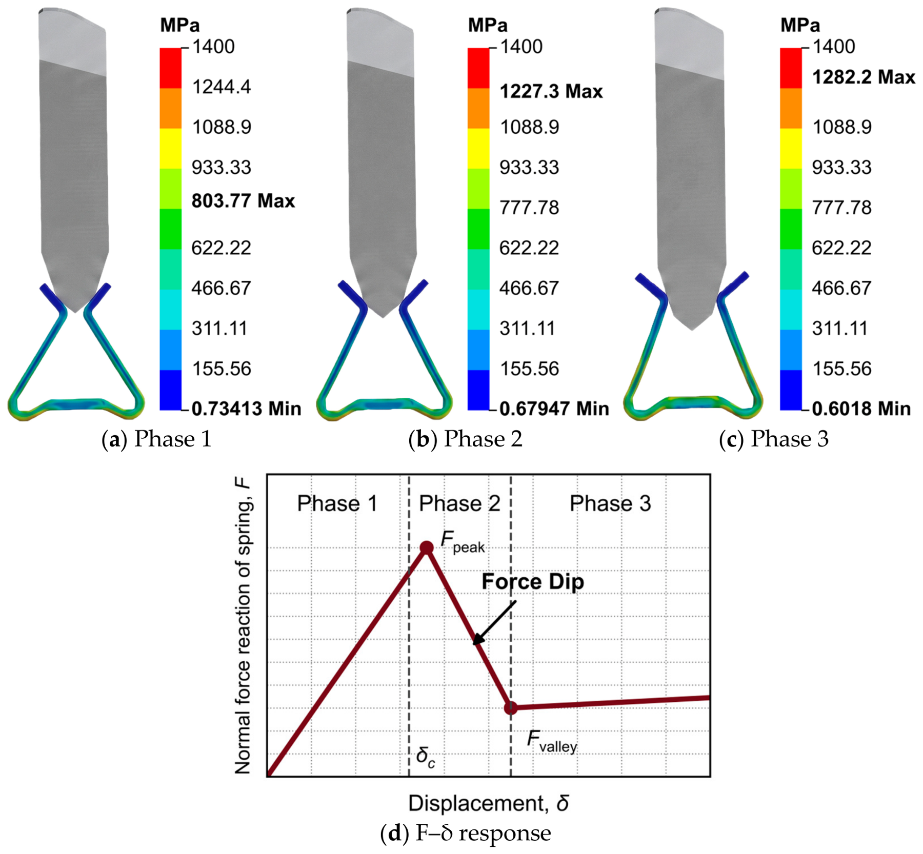
Figure 5 illustrates the Force Dip mechanism produced by the dual-angle insert.
In the Phase 1 contact state of Figure 5a, the insert contact region (α1, the chamfer surface) slides on the clip spring in a line-contact state. The vertical descent of the insert acts as a wedge force that spreads the clip spring to both sides, and because it must overcome both the elastic deformation force of the spring and the frictional resistance on the inclined surface, the reaction force of the insert increases monotonically and reaches its maximum.
In the Phase 2 contact state of Figure 5b, as the insert descends further, the line-contact position passes through the edge boundary between the α1 and α2 regions. The normal vector of the contact surface then rotates rapidly, and the vertical resistance-force component decreases sharply. This rapid transition of the load-bearing vector directly causes the Force Dip and produces a negative-incremental-stiffness segment in Phase 2. This descending branch is distinct from the low-incremental-stiffness plateau that follows in Phase 3.
In the Phase 3 stage of Figure 5c, the insert continues to descend and slides in a line-contact state on the α2 inclination of the insert. In this section, the elastic restoring force of the spring acts largely transverse to the direction of insert descent. The vertical resistance is reduced because the penetration-direction component of the normal contact force decreases, while frictional resistance becomes relatively more influential. The combined normal and friction contributions therefore maintain a low-level plateau with a small positive residual stiffness. This Phase 3 response is identified as a QZS-like low-incremental-stiffness plateau. Figure 5d shows the resulting F–δ behavior.
This transition from the chamfer surface, through the edge boundary, to the upper inclined surface (α2) represents the essence of the proposed Force Dip mechanism and is a defining characteristic of the proposed dual-angle geometry.
Figure 5.
Force Dip mechanism of the dual-angle chamfer insert: (a) Phase 1—line contact on the lower chamfer α1; (b) Phase 2—passing through the edge boundary; (c) Phase 3—sliding on the upper chamfer α2; (d) schematic F–δ response. In panels (a–c), the colors represent the magnitude of the equivalent (von Mises) stress according to the adjacent color bars in MPa. The results are plotted on a common 0–1400 MPa scale, with maxima of 803.77, 1227.30, and 1282.20 MPa for Phases 1, 2, and 3, respectively. Panel (d) is a schematic of the resulting F–δ profile that defines the critical displacement δc, the peak force Fpeak, and the valley force Fvalley; the corresponding quantitative values are presented in the Results section.
2.4. Passive Self-Equilibrating Chamfer-Depth Setting
In the top chamfering stage, the chamfer depth ap is expressed by the static equilibrium condition between the reaction force Fwall and the spring restoring force Fspring, as given by Equation (1).
Here, vf is a cutting-condition parameter in the wall-reaction term rather than an inertial term. Owing to the geometric constraint in which insert retraction and edge depth of cut correspond one-to-one, δ ≡ ap holds. During chamfering, the operating point approaches the end of Phase 1, where the steep positive stiffness provides the high reaction required for burr engagement and limits movement of the equilibrium point. The resulting depth is therefore interpreted as a passive self-equilibrating chamfer-depth setting for the present configuration. During hole entry and passage, continued axial motion imposes additional insert retraction, carrying the contact through the Phase 2 Force Dip transition, where the incremental stiffness is negative, and into the Phase 3 QZS-like low-incremental-stiffness plateau. In this plateau, the contact force remains at a lower level and varies only slightly with further displacement. By contrast, the single-angle insert maintains dFspring/dδ > 0 over the full range, so its contact force continues to rise during hole passage. Thus, the chamfering and hole-passage stages use distinct portions of the same force–displacement response.
3. Numerical Analysis Model
3.1. Governing Equations and Boundary Conditions
The insert indentation simulation was modeled as a quasi-static contact problem including geometric nonlinearity. Because the mass of the clip spring is very small, the influence of inertial forces is negligible, and the machining depth is determined by the static equilibrium of the displacement-based spring restoring force; the quasi-static assumption is therefore valid. The governing equations consist of the static equilibrium equation of Equation (2) and the Dirichlet and Neumann boundary conditions within the analysis domain Ω.
Here, σ is the Cauchy stress tensor and b the body force vector per unit volume; in this analysis, since the influence of self-weight is negligible, the body force was neglected. The weak form of Equation (2), obtained by applying the principle of virtual work, was taken as the starting point of the finite element discretization [17,18]. In addition, to properly reflect the finite rotation and large deformation of the clip spring during indentation, a large-deformation elastoplastic analysis was performed in ANSYS under the Updated Lagrangian formulation, using the rate of deformation tensor together with the Jaumann objective stress rate [19].
3.2. Elastoplastic Constitutive Model of SUS301H
The elastoplastic behavior of SUS301H was modeled by combining the von Mises yield criterion, the associated flow rule, and the multilinear isotropic hardening (MISO) law [20]. It follows a standard J2 plasticity formulation that combines the additive decomposition of strain into elastic and plastic parts, the generalized Hooke’s law, the associated flow rule based on the yield function f(σ, ) = ‖s‖ − √(2/3)σy() ≤ 0, and the loading/unloading conditions that determine the onset and cessation of plastic flow [20]. The multilinear isotropic hardening law expresses the yield stress as a piecewise-linear function of the accumulated equivalent plastic strain, as given in Equation (3).
Here, (, ) is the i-th data point of the hardening curve, and Hi is the hardening modulus of the i-th interval. The post-yield true stress–plastic strain curve was input as ten data points up to = 1.0 and interpolated in the form of Equation (3).
The elastic properties of this model are a Young’s modulus E = 193 GPa, a Poisson’s ratio ν = 0.3, and a density ρ = 7900 kg/m3, from which the shear modulus G = 74.2 GPa and the bulk modulus K = 161 GPa are derived. The initial yield stress σy(0) = 930 MPa and the final input-point stress of the hardening curve σy(1.0) = 1460 MPa were applied. The chamfer insert, which is made of cemented carbide (WC–Co), and the floor were treated as rigid bodies. Because a rigid body transmits load without deforming, its material data do not enter the solution, and the Workbench default Structural Steel entry was therefore retained for both. The rationality of this idealization, and the calculation error it introduces, are quantified in Section 3.3 by means of a companion analysis in which the insert is assigned linear-elastic cemented-carbide properties. The stress–strain data of SUS301H were taken from the strain-hardening curve reported in the prior literature [21] and input into the multilinear isotropic hardening model.
3.3. Finite Element Discretization and Mesh Configuration
The nonlinear matrix equation obtained by applying the standard Galerkin method to the weak form of Equation (2) was solved using the full Newton–Raphson method [17,22,23]. The tangent stiffness is decomposed into material, geometric, and contact contributions, as expressed in Equation (4). Line search and nonlinear stabilization were applied to ensure numerical stability when the tangent stiffness approached a near-singular state in the Force Dip region [17,23,24].
Here, [Kmaterial] is the material stiffness matrix derived from the constitutive law, [Kgeometric] is the geometric stiffness matrix reflecting the stress-stiffening effect, and [Kcontact] is the contact stiffness contribution obtained by linearizing the normal and tangential contact constraints.
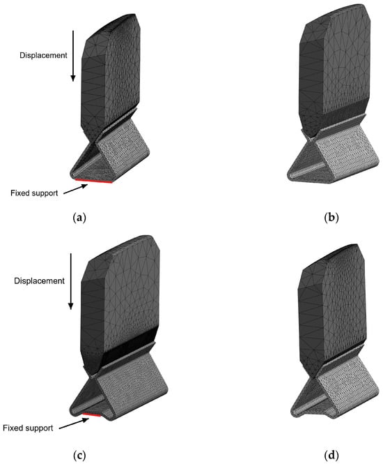
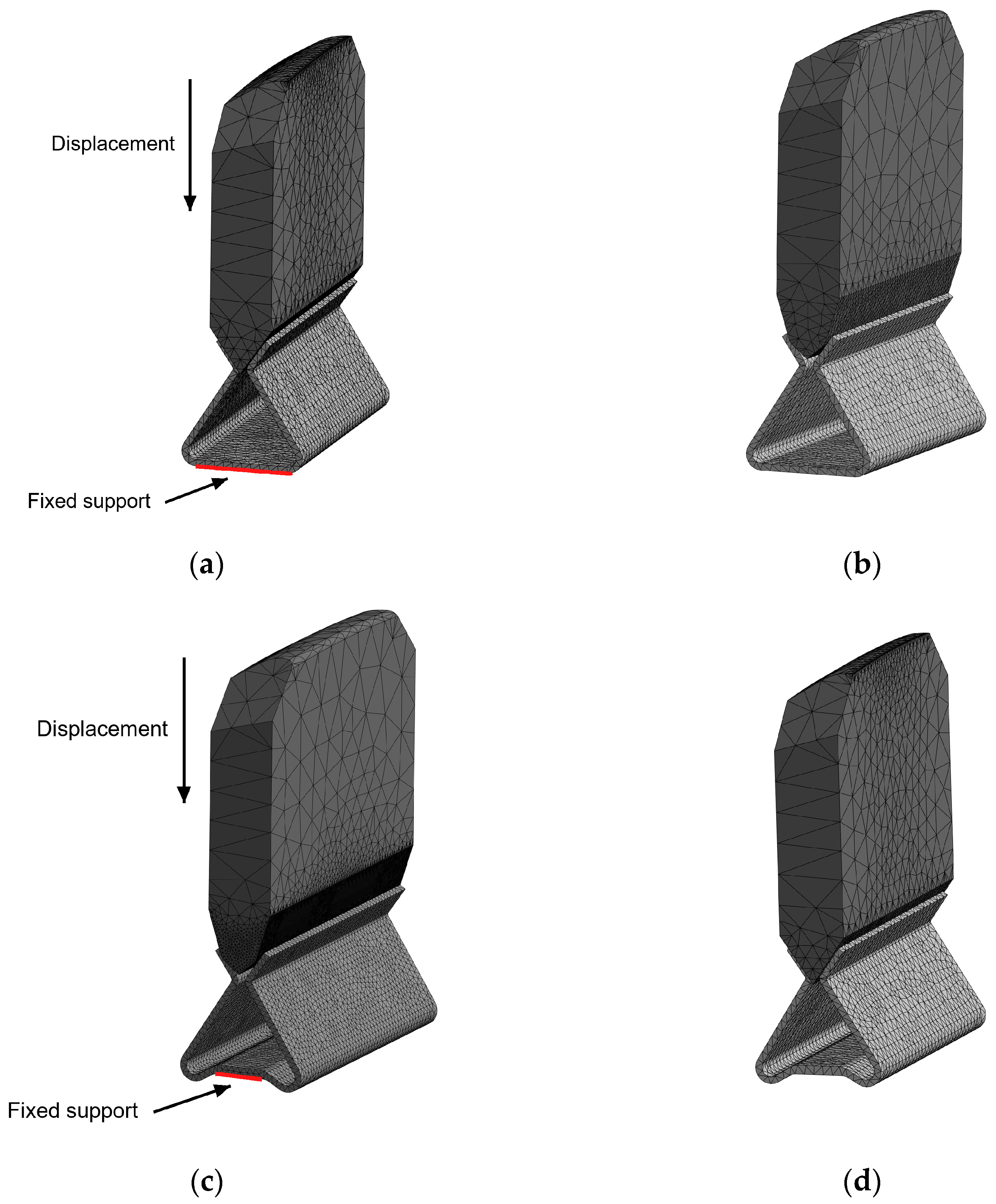
Figure 6 shows the overall geometry and the corresponding mesh configuration used for the FEA model. The clip spring was discretized with SOLID187 ten-node higher-order tetrahedral elements, and the Patch Conforming algorithm was applied to generate the mesh. A Body Sizing of 0.3 mm was assigned to the overall spring body, and, in addition, a finer mesh with a Face Sizing of 0.05 mm was applied to the six chamfer-insert faces that come into direct contact with the clip spring, so that the interface discretization resolves the α1/α2 transition edge, from which the Force Dip originates, with sufficient accuracy. The chamfer insert itself, made of cemented carbide (WC–Co), is treated as a rigid body and is represented by surface (target) elements driven by an automatically generated pilot node. Analyses were carried out for all four cases obtained by combining the insert geometry (single-/dual-angle) with the bottom shape (flat/embossed).
Figure 6.
Combined geometries, FEA meshes, and boundary conditions for the four comparison cases: (a) Case 1: single-angle + flat; (b) Case 2: dual-angle + flat; (c) Case 3: dual-angle + embossed; (d) Case 4: single-angle + embossed. Panels (a,c) show the applied boundary conditions: the downward arrow denotes the prescribed displacement of the chamfer insert, whereas the lower arrow and red line denote the fixed support at the bottom edge of the clip spring.
Because the predicted Force Dip originates from a rapid contact transition near the boundary between the two insert inclinations, the adequacy of the local mesh density in this region was verified by a convergence study. The refinement was applied progressively to the face sizing of these insert contact faces. Three levels were compared for Case 3 (face sizing h = 0.050, 0.043 and 0.037 mm, spanning a 1.35-fold range in local element size), while the clip-spring body sizing, contact formulation, friction coefficients and load-step controls were held fixed. The results are reported in Table 1 as deviations from the production level (face sizing 0.05 mm), since the purpose of the study is to quantify the sensitivity of the metrics to discretization rather than to reproduce absolute force levels. The geometric critical displacement δc, introduced in Section 3.4, denotes the onset of the contact-angle transition, whereas the peak displacement δpeak is the position at which the peak reaction force occurs. The two are not identical; δpeak is monitored separately as a directly identifiable response metric and is reported throughout as the position metric.
Table 1.
Contact-mesh convergence study for Case 3, expressed as deviations from the production face sizing of 0.050 mm. Only the face sizing of the insert contact faces was varied; all other settings were held fixed, and the node and element counts document the degree of refinement.
The peak force varied by at most 0.76%, the peak displacement and the valley force were unchanged to four significant figures, and the Force Dip ratio varied by at most 0.20 percentage points, the two coarser levels returning identical results in all four metrics. Because an observed order of convergence could not be evaluated under these conditions, a formal Richardson extrapolation was not meaningful; the maximum observed mesh-induced variation is therefore reported in place of a formal error estimate. The 0.05 mm level, which corresponds to the face sizing of the production model, was adopted as the mesh level for the subsequent analyses, and identical mesh controls were applied to all four cases. The mesh-convergence study was conducted for Case 3 because it exhibits the most abrupt contact transition of the four configurations.
The rigid-body idealization of the chamfer insert neglects its elastic deformation. To quantify the resulting error, the Case 3 analysis was repeated with the insert assigned linear-elastic cemented-carbide properties (WC–Co), using representative hardmetal properties E = 600 GPa, ν = 0.22 and ρ = 14,500 kg m−3 [25,26]. A linear-elastic model was adopted because the computed stresses remain far below the compressive-strength range reported for these materials, so that no nonlinear material response is expected under the present loading condition. Relative to the rigid-insert baseline, the peak reaction force increased by 4.7%, whereas the valley force changed by 0.1%, the mean force over the Phase 3 plateau by less than 0.1%, and the integrated response ∫F dδ over the full stroke by only 0.24%. The influence of the idealization is therefore confined to the immediate vicinity of the peak, where the contact load is highest. Because the Force Dip ratio is referred to the peak force, it shifts correspondingly by 1.2 percentage points, while the valley force and the plateau level on which the residual-force requirement is based remain unchanged. This magnitude is consistent with the elastic deformation of the insert itself: the peak von Mises stress within the insert was 120.6 MPa, attained at essentially the same displacement as the peak reaction force, and the corresponding elastic strain σ/E = 2.0 × 10⁻⁴ gives a deflection of the order of 1 μm along the load path, i.e., 0.3% of the peak displacement of approximately 350 μm. The insert secant stiffness of about 1.3 × 10⁸ N m−1 accordingly exceeds that of the 0.2 mm clip spring loaded in bending (3.8 × 10⁵ N m−1) by more than two orders of magnitude, and the stress level, only 2.2–3.0% of the compressive strength of cemented carbide (4000–5500 MPa), indicates that nonlinear deformation of the insert is unlikely under the present loading condition. Over the range of elastic moduli reported for WC–Co hardmetals, approximately 520–650 GPa [25,26], the computed insert deflection varies only between 0.9 and 1.2 μm, so that this conclusion does not depend on the precise grade. The rigid-body idealization therefore reproduces the overall force–displacement behavior, agreeing to 0.24% in integrated terms and to better than 0.1% in the valley force and the plateau level, and underestimates the local maximum reaction force at the contact transition by 4.7%. It is retained as the baseline because the component whose deformation defines the Force Dip is the 0.2 mm clip spring, not the insert.
3.4. Contact Algorithm and Friction Model
This model defines three frictional contact pairs Γc between the insert and the spring and between the spring and the floor [27]. The non-penetration condition is expressed as a complementarity condition, and the contact pressure was iteratively corrected by the Augmented Lagrange method to suppress penetration [27,28]. The tangential friction was modeled by the Coulomb law of Equation (5), based on the standard formulation of classical contact mechanics and computational contact analysis [27,29].
Here, τt is the tangential contact stress vector, μ is the nominal Coulomb friction coefficient, pn is the normal contact pressure, and ‖·‖ is the Euclidean norm. Because the aim of the analysis was to compare the relative effects of the insert geometry and the spring bottom shape, a nominal Coulomb friction coefficient of μ = 0.30 was applied uniformly to all three contact pairs across the four cases. The justification for this value, together with a sensitivity study over a representative friction range, is presented at the end of this section. The vertical reaction force Fy(δ) at the insert pilot node is expressed as in Equation (6), based on chamfer-crossing mechanics [30] and the load-decomposition model of compliant chamfering tools [1], as the sum of the penetration-direction components of the normal forces Ni and friction forces associated with the n local contact components at the insert–spring interface, in accordance with the dual-angle contact geometry.
Here, δ is the insert indentation displacement, Ni is the normal force of the i-th contact pair, and θ(δ) is the half-angle that the contact surface makes with the insert axis, corresponding to half of the total included angle of the contact region. Owing to the macroscopic contact-phase transition of the dual-angle insert, the contact angle θ(δ) is derived as a piecewise function that changes discontinuously at the critical displacement δc, similarly to QZS kinematics [15].
Because α1 > α2, the sin θ weighting in Equation (6) drops sharply at δ = δc, which is the basis for the Force Dip, in which Fy(δ) decreases non-monotonically despite the increase in N(δ) due to elastoplastic deformation. In particular, when the contact angle decreases, the penetration-direction component of the friction force increases somewhat; however, under typical friction conditions, this increase does not offset the decrease in the penetration-direction component of the normal force, so the load-bearing coefficient of Equation (6) decreases overall. Whereas conventional passive QZS mechanisms combine positive- and negative-stiffness branches [13,14,15], the proposed mechanism produces the desired non-monotonic force profile through a contact-angle transition without an additional negative-stiffness element. Accordingly, Phase 2 is identified as the Force Dip transition with negative incremental stiffness, whereas Phase 3 is the QZS-like low-incremental-stiffness plateau.
The nonlinear quasi-static finite element analysis was performed in ANSYS, and to ensure numerical stability against the abrupt change in contact geometry occurring in the Force Dip region, the contact stiffness was updated at every iteration and viscous stabilization damping together with energy-based nonlinear stabilization was applied [31].
The same boundary conditions were applied to all four cases, as illustrated for Cases 1 and 3 in Figure 6a,c. The floor was fixed by constraining all translational and rotational degrees of freedom, and a fixed support to prevent rigid-body motion was applied to one bottom edge of the clip spring. The chamfer insert was indented 1.0 mm toward the clip spring, and all degrees of freedom other than the indentation direction were constrained to block the rigid-body motion of the insert. The vertical reaction force Fy(δ) measured at the rigid pilot node of the insert is calculated as the sum of the penetration-direction components of the integral of the normal contact force over the insert–clip-spring contact pair, which corresponds to the restoring force Fspring(δ) of the clip spring.
The value μ = 0.30 was adopted as a nominal comparative parameter rather than as an experimentally identified interface property. The chamfer insert is made of cemented carbide (WC–Co) and the contact surfaces were assembled dry and unlubricated. Because friction contributes directly to the penetration-direction reaction force in Equation (6), and particularly to the Phase 3 plateau, a sensitivity study was carried out over μ = 0.15–0.40 for Case 3 and over μ = 0.15–0.50 for Case 4, with all other parameters held fixed within each series. The results are summarized in Table 2 for five response metrics (peak force, valley force, Force Dip ratio, residual stiffness and peak displacement), normalized to the μ = 0.30 condition of each case; they are used to evaluate relative sensitivity trends rather than to reproduce absolute force levels. The residual stiffness kres is evaluated as the slope of the force–displacement response over 0.75 ≤ δ ≤ 0.98 mm, which lies entirely within the Phase 3 plateau. For Case 3 the peak force was well approximated by an exponential trend over the investigated friction range, with a factor of 1.61 per 0.1 increment in μ (R2 = 0.992), whereas the peak displacement varied by only 1.4%, the valley force by less than 0.2% and the residual stiffness by less than 0.3% over the entire range. For Case 4, the corresponding factor was 1.17 per 0.1 increment (R2 = 0.9997), i.e., approximately three times less sensitive than the dual-angle configuration. Friction therefore governs the magnitude of the peak force but not the displacement at which it occurs, and the invariance of both the valley force and the residual stiffness indicates that these two descriptors of the Phase 3 plateau are relatively insensitive to friction within the investigated range and are predominantly governed by the α2 contact geometry. The contrast runs counter to the expectation that friction is most influential in the Phase 3 plateau: over the investigated range, the peak force varied by a factor of 3.3, whereas the valley force and the residual stiffness varied by less than 0.3%. An effective friction coefficient estimated solely by peak-force matching against the Case 4 compression test lies in the range μ = 0.33–0.37, close to the nominal value adopted here. Because such an estimate also absorbs thickness, angle and seating deviations, it is reported as an indication that the residual discrepancy observed for Case 4 is consistent with interface-friction uncertainty rather than as an independent measurement of the interface friction coefficient.
Table 2.
Friction sensitivity of the five Force Dip metrics, normalized to the μ = 0.30 condition of each case. kres denotes the residual stiffness of the Phase 3 plateau. — denotes a monotonic response with no Force Dip and hence no plateau. For μ = 0.15, the Phase 1 peak is reported, an isolated single-substep excursion occurring later in the transition region.
The geometry imported from CAD contained initial assembly clearances of 0.68, 8.59 and 21.36 μm at the spring–floor, spring–α1 and spring–α2 interfaces, respectively, which were closed by the Adjust-to-Touch interface treatment in the corresponding zero-clearance reference analysis. To quantify the influence of this assumption, Case 3 was re-analyzed with the clearances retained. The peak displacement shifted by +7.5 μm (+2.1%), a value that corresponds closely to the 8.59 μm gap at the α1 interface, which governs the onset of the peak, while the peak force decreased by 3.7% and the Force Dip ratio changed by only 0.2 percentage points. The valley force and the full-stroke integrated response decreased by 4.4% and 4.1%, respectively, so that the influence of the retained clearance remained within approximately 5% for all evaluated metrics, indicating limited sensitivity to the measured assembly clearances under the tested condition. Table 3 summarizes this verification together with that of the rigid-insert idealization of Section 3.3.
Table 3.
Verification of the two modeling assumptions for Case 3, expressed as deviations from the corresponding reference run of each paired analysis. ∫F dδ denotes the reaction force integrated over the full stroke.
The present study was designed as a mechanism-verification study based on the fabricated prototype rather than as a full geometric optimization. The clip-spring thickness (T = 0.2 mm) and the insert inclination angles (α1, α2) were therefore fixed at the prototype dimensions so that the effects of contact topology and spring-bottom shape could be isolated; these two factors are varied systematically in the four-case comparison of Section 4.1. No claim is made that the selected values are optimal, and their continuous parametric effects will be investigated in future work.
4. Results and Discussion
4.1. Numerical Analysis Results
The clip spring used in all analyses had a thickness T = 0.2 mm, a length H = 9.5 mm, an upper angle A = 70°, and a lower angle B = 65°. Under these common clip-spring dimensions, two types of chamfer insert geometry were compared: a single-angle insert with β = 70° and a dual-angle insert with α1 = 100° and α2 = 35°. Thus, the contact geometry of the chamfer insert was classified as either single-angle or dual-angle, while the bottom shape of the clip spring was classified as either flat or embossed. Based on these two design factors, four comparison cases were defined by combining the insert geometry and the clip-spring bottom shape. Case 1 is the combination of a single-angle insert and a flat bottom, Case 2 is the combination of a dual-angle insert and a flat bottom, Case 3 is the combination of a dual-angle insert and an embossed bottom, and Case 4 is the combination of a single-angle insert and an embossed bottom. Through this case arrangement, the effects of the chamfer insert geometry and the clip-spring bottom shape on the reaction force response can be compared systematically. Table 4 summarizes the definition and force–displacement analysis results of each case.
Table 4.
Definitions and F–δ analysis results for the four comparison cases.
The comparison is interpreted at the mechanism level: the insert angle controls the existence of a Force Dip, whereas the spring-bottom shape primarily tunes the available peak force. The following response curves are evaluated against this force-profile criterion before the machining observations are considered.
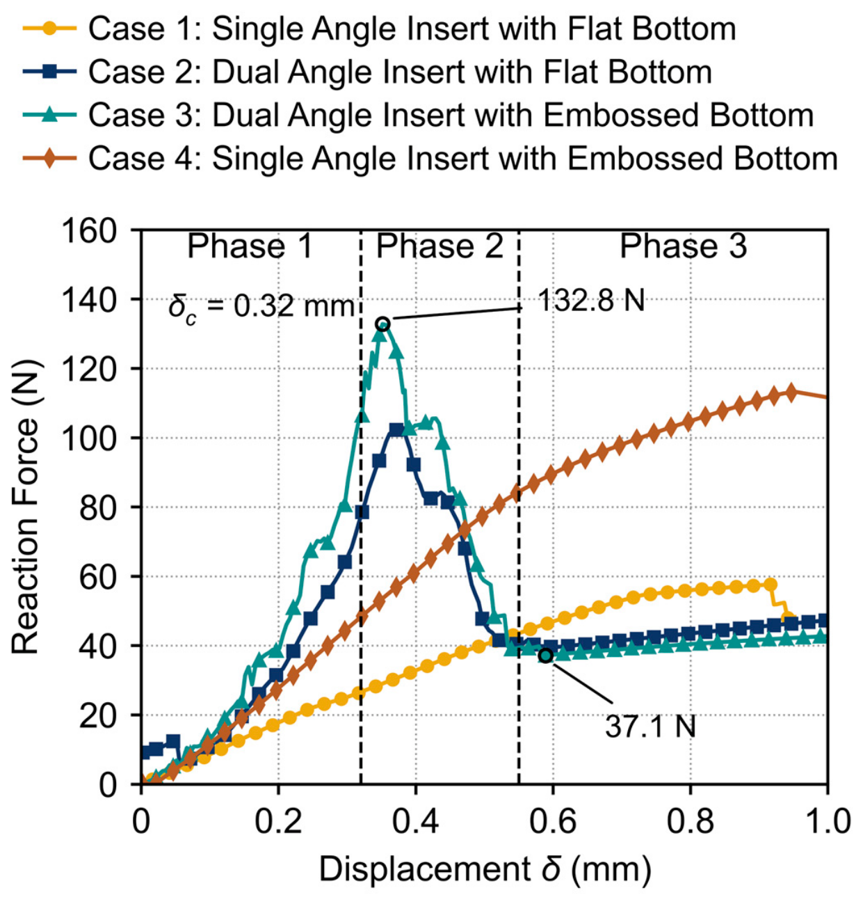
Figure 7 shows the comparison of the reaction force curves of the four cases as a function of displacement. The behavior of the four cases is broadly divided into two types according to the geometry of the chamfer insert. Cases 1 and 4, which use single-angle inserts, exhibit a monotonically increasing reaction force response with increasing displacement, whereas Cases 2 and 3, which use dual-angle inserts, exhibit a Force Dip behavior in which the reaction force rises and then sharply drops over a specific displacement range.
For the single-angle inserts, the reaction force of Case 1 with the flat bottom increased monotonically up to a maximum of 57.7 N at a displacement of 0.92 mm, and no Force Dip appeared. Case 4 with the embossed bottom likewise exhibited a monotonically increasing response, but, owing to the additional support effect of the embossed bottom, it reached a maximum of 113.3 N at a displacement of 0.95 mm, forming a reaction force about 1.96 times as high as that of Case 1.
This monotonic behavior arises because, for the single-angle insert, the contact region moves only over the single inclined surface, so the effective stiffness increases monotonically with displacement; therefore, the Force Dip does not appear regardless of the bottom shape.
In contrast, for the dual-angle inserts, the reaction force of Case 2 with the flat bottom reached a maximum of 102.8 N at a displacement of 0.38 mm and then decreased to 39.7 N at a displacement of 0.61 mm, forming a Force Dip of about 61.4%. The reaction force of Case 3 with the embossed bottom reached a maximum of 132.8 N at a displacement of 0.35 mm and then decreased to 37.1 N at a displacement of 0.59 mm, forming a Force Dip of about 72.0%. This Force Dip behavior follows the same three-stage contact-phase transition described in Figure 5. In Phase 1, from a displacement of 0 to 0.32 mm, the lower inclined surface α1 of the insert contact region slides in line contact with the clip spring, and the reaction force rises steeply to its maximum. Next, in Phase 2, from a displacement of 0.32 mm to 0.55 mm, the line-contact position passes through the edge boundary between the two inclination angles, so that the contact angle switches discontinuously as in Equation (7) and the reaction force drops sharply. However, although in the idealized model the transition occurs immediately at the critical displacement δc = 0.32 mm, in the actual FEA the maximum reaction force is observed at δ ≈ 0.35–0.38 mm, just after δc, owing to the finite mesh curvature near the edge and local elastoplastic deformation. The mesh-convergence assessment reported in Section 3.3 indicates that the offset was not materially affected by mesh refinement over the investigated range: refining the contact mesh over a 1.35-fold range left the peak displacement unchanged to four significant figures. Finally, in Phase 3, from a displacement of 0.55 mm to 1.0 mm, the reaction force maintains a low-level plateau because the penetration-direction component of the normal contact force is reduced, while frictional resistance on the upper inclined surface α2 becomes relatively more influential. Meanwhile, although both cases formed a Force Dip over a similar displacement range, the maximum reaction force of Case 3 with the embossed bottom was about 1.29 times as high as that of Case 2, an increase of 30.0 N in absolute terms.
These results distinguish the roles of the two design variables. The geometry of the chamfer insert determines whether the Force Dip appears, and among the single-angle and dual-angle inserts, the Force Dip appears only with the dual-angle insert. By contrast, the bottom shape of the clip spring regulates the magnitude of the maximum reaction force regardless of whether the Force Dip appears: when the embossed bottom is applied, the reaction force increased from 57.7 N to 113.3 N for the single angle and from 102.8 N to 132.8 N for the dual angle. Therefore, the Force Dip is governed by the dual-angle insert and the reaction force magnitude by the embossed bottom.
Figure 7.
Comparison of force–displacement (F–δ) curves for the four cases. The critical displacement δc and the peak and valley forces of the representative dual-angle case (Case 3) are marked; the phase boundaries correspond to Phases 1–3 defined in Figure 5d.
4.2. Compression Test Validation
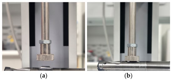
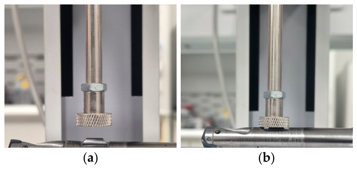
Figure 8 shows the compression test apparatus. The fabricated clip spring specimen is placed on the fixed lower jig, and the upper jig compresses it quasi-statically up to a displacement of 1.0 mm at a constant crosshead speed of 5 mm/min.
Figure 8.
Clip spring compression test setup using a tension–compression tester: (a) before loading; (b) during compression of the clip spring.
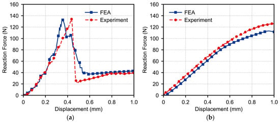
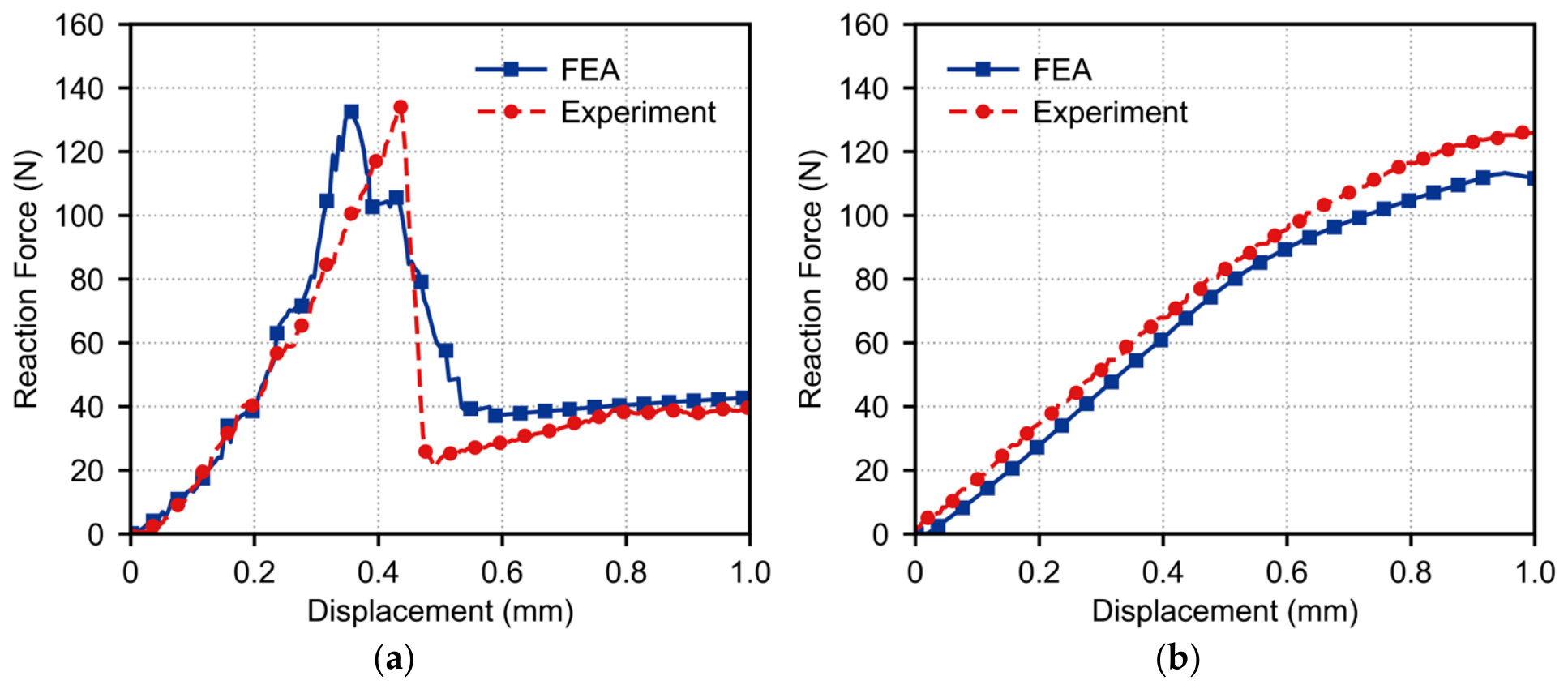
Figure 9 compares the FEA results and the compression test results for the Case 3 and Case 4 models. For each of the Case 3 and Case 4 configurations, the compression test was performed on a single fabricated clip spring specimen, which was loaded five times under identical loading conditions. The measured force–displacement curves showed consistent response characteristics, and their average was used as the representative experimental curve. In Figure 9a, the maximum reaction force obtained from the FEA was 132.8 N, which agreed with the experimental average maximum reaction force of 133.5 N within an error of about 0.6%, and the Pearson correlation coefficient for the shapes of the two curves was r = 0.916, indicating a very strong correlation. Moreover, in the Phase 3 steady-state region, the reaction forces of the FEA and the experiment converged to about 40 N and 36 N, respectively, so that the maximum reaction force and the steady-state reaction force agree to within about 1% and 10%, respectively. In terms of effective stiffness, the measured loading stiffness in Phase 1 was approximately 320 N/mm. The Phase 3 low-force plateau (δ ≈ 0.55–1.0 mm) exhibited a residual stiffness of approximately 25 N/mm—less than 10% of the loading stiffness—over a stable operating range of approximately 0.45 mm, while the Force Dip transition itself occurred in Phase 2 (δ = 0.32–0.55 mm). In Figure 9b, both the FEA and the experiment exhibited a monotonically increasing reaction force over the entire displacement range without a Force Dip, experimentally confirming the analytical result that the Force Dip does not appear with the single-angle insert. The experimental average maximum reaction force was about 126 N, about 11% higher than the FEA maximum reaction force of 113.3 N; however, the shapes of the two curves and the trend of increasing stiffness agreed well over the entire range. This difference in reaction force may reflect a deviation of the actual interface friction from the nominal coefficient μ = 0.30, together with thickness and angle deviations arising from manufacturing tolerances of the thin-plate clip spring. Because the peak force scales strongly with the assumed friction coefficient—by a factor of 3.3 over the range examined in Table 2—the close agreement obtained for Case 3 should not be read as an independent determination of μ; an effective coefficient obtained by peak-force matching lies at μ = 0.33–0.37, as reported in Section 3.4. The descriptors that are insensitive to friction are the valley force and the Phase 3 residual stiffness, which vary by less than 0.3% over the same range; it is their agreement, together with the reproduction of the Force Dip itself, that constitutes the mechanism-level validation.
Figure 9.
Comparison of the FEA and compression test results: (a) Case 3; (b) Case 4.
Because the five repetitions were conducted on the same specimen, the reported variability represents within-specimen repeatability but does not quantify specimen-to-specimen reproducibility. Additional tests on independently manufactured clip springs are required to assess the influence of thickness, bending angle, embossing, and initial clearance tolerances on peak force, Force Dip ratio, and critical displacement.
Meanwhile, in Figure 9a, the displacement position at which the maximum reaction force appears differed somewhat between the FEA at δ = 0.35 mm and the experiment at δ = 0.44 mm, and in the descending pattern immediately after the maximum reaction force, the experimental curve also decreased more sharply than the FEA. This displacement-position difference likely stems from the accumulation of kinematic factors such as the initial clearance between the compression jig and the clip spring during specimen seating, the compliance of the compression head and jig, and the difference in initial contact position caused by the manufacturing tolerance of the clip spring, so that the displacement response was measured with a delay in the actual compression test. However, since the magnitude of the maximum reaction force, the Phase 3 steady-state reaction force, and the occurrence of the Force Dip itself appear consistently in both the FEA and the experiment, the present analysis model captures the key features of the clip-spring compression behavior. The consistent occurrence of the Force Dip over the five repeated tests confirms the within-specimen repeatability of the characteristic force–displacement response under repeated loading and shows that the analysis model reproduces the peak reaction force level and Force Dip behavior of the clip spring.
4.3. Machining Test with the Force Dip Mechanism
To assess whether the mechanism-level Force Dip response can be translated into the actual drilling-chamfering sequence, a one-step drilling–chamfering test was performed. The spindle speed was 1200 rpm in drilling and 1000 rpm in chamfering. The axial feed rate was reduced from 3.5 mm/s during drilling to 0.2 mm/s during top/bottom chamfering for stable hole machining, since the feed rate is known to be a dominant factor governing the thrust force in drilling [32]. The target chamfer-depth requirement was 0.3–0.5 mm.
The primary machining criterion was force-profile transfer: under actual rotation and feed, the dual-angle geometry had to preserve high-force burr engagement followed by lower hole-wall contact during passage. This transition was anticipated from the Case 3 force–displacement curve and independently supported by the FEA and compression-test agreement. Accordingly, the machining results are evaluated through hole-wall roughness measurements and visual inspection, while the quantitative validation of the Force Dip mechanism itself is provided by the matched force–displacement response. Because in-process forces were not measured, the machining results provide indirect evidence consistent with, rather than direct validation of, force-profile transfer.
A direct validation of force-profile transfer would require synchronized measurements of axial thrust, torque, and preferably radial contact force throughout the drilling–chamfering cycle. The present machining results should therefore be interpreted as evidence of process feasibility and surface-quality improvement rather than as a direct measurement of the Force Dip under rotating cutting conditions.
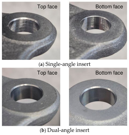
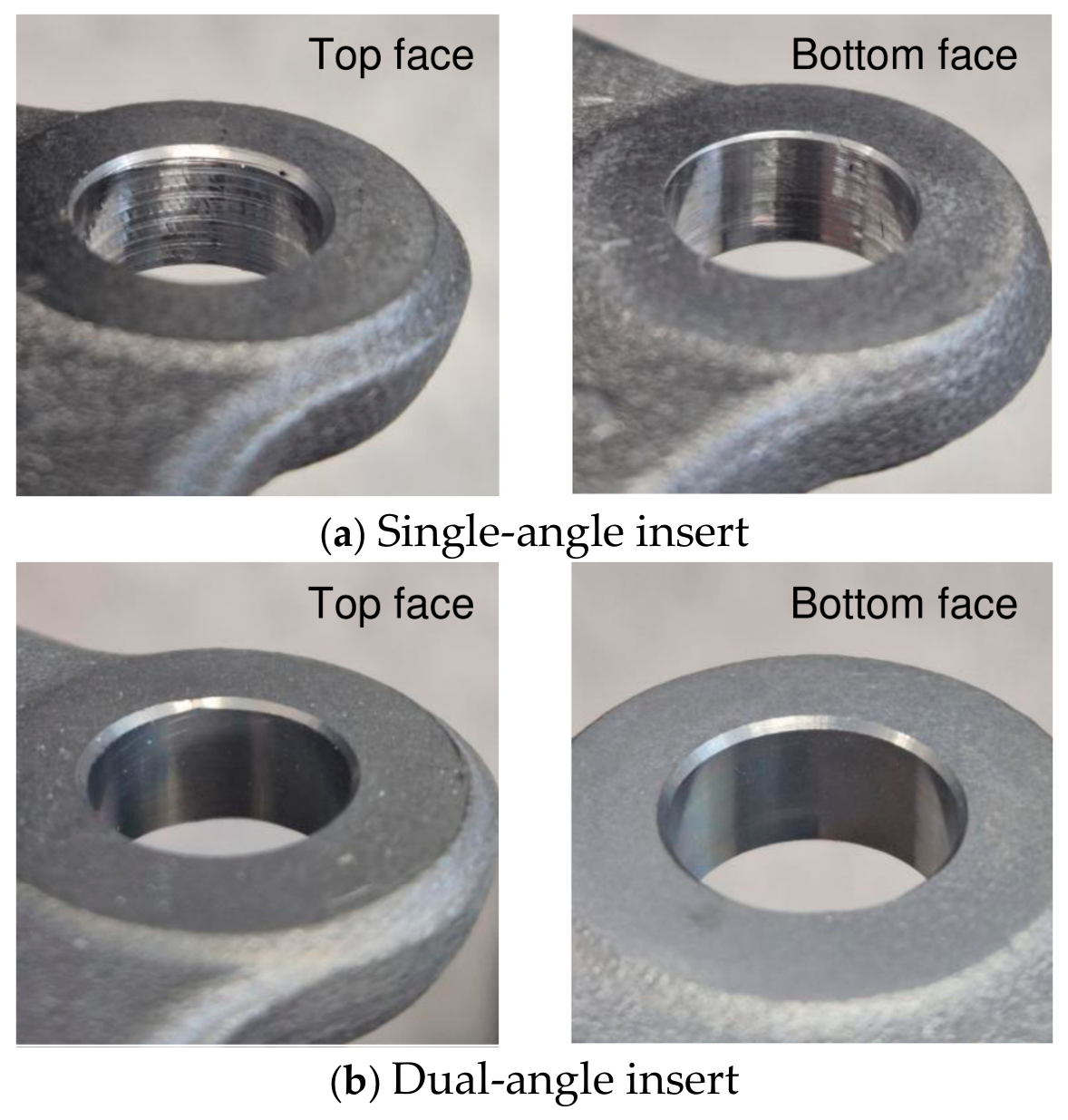
Figure 10 provides a qualitative visual comparison of the hole inner surfaces after one-step machining with the single-angle and dual-angle inserts.
Figure 10.
One-step drilling–chamfering test results—comparison of the hole inner surfaces: (a) single-angle insert; (b) dual-angle insert.
In the single-angle condition, scratch-type contact marks were visually observed on both faces of the hole, as shown in Figure 10a. This observation is consistent with the monotonic reaction force response, which maintains a high contact force during hole passage.
In the dual-angle condition, no visible scratch-type marks were observed under the tested settings, as shown in Figure 10b. This qualitative difference is consistent with the Force Dip response: after burr engagement, the reaction force drops and the Phase 3 plateau maintains a lower contact force during hole passage. Such control of the tool–workpiece contact through tool geometry and compliance is likewise a central design concern in recent precision finishing attachments [33]. To quantify this difference, the hole-wall roughness was measured with a stylus profilometer (Surftest SJ-301, Mitutoyo) with a cutoff length of 0.8 mm and five sampling lengths. For each condition, three independently machined holes were measured, with five axial traces taken on each hole at different circumferential locations of the inner wall. The single-angle insert produced Ra = 1.71 ± 0.18 μm, Rq = 2.15 ± 0.14 μm, and Rz = 9.40 ± 0.74 μm (mean ± standard deviation over the 15 traces per condition), whereas the dual-angle insert reduced these to Ra = 0.43 ± 0.11 μm, Rq = 0.54 ± 0.15 μm, and Rz = 2.82 ± 0.50 μm—an approximately fourfold reduction in Ra. These measurements are consistent with the lower-contact-force regime predicted by the FEA and observed in the compression tests. The test also confirmed one-step drilling and top/bottom chamfering. Chamfer depth was measured with an optical microscope on both the top and bottom chamfers of the three independently machined holes per insert condition, that is, the same holes used for the roughness measurements. All twelve measurements (two chamfers × three holes × two insert conditions) fell within 0.335–0.339 mm, with a mean of 0.337 mm, satisfying the target range and demonstrating consistent passive depth setting under the tested conditions.
5. Conclusions
This study establishes a passive Force Dip mechanism for a clip-spring-based tool that performs drilling and top/bottom chamfering in one process. The central contribution is not the integration of operations alone, but the intentional generation of a non-monotonic force sequence through the dual-angle insert–clip-spring contact. This sequence comprises a negative-incremental-stiffness Force Dip transition followed by a QZS-like low-incremental-stiffness plateau, separating high-force burr engagement from lower-force hole passage and providing passive self-equilibrating chamfer-depth setting under the tested condition. The four combinations of insert geometry and spring-bottom shape were analyzed by nonlinear quasi-static FEA.
The contact geometry of the chamfer insert determined whether the Force Dip occurred: the single-angle insert produced a monotonically increasing response, whereas the dual-angle insert generated a negative-incremental-stiffness transition followed by a QZS-like plateau. The spring-bottom shape, by contrast, regulated the magnitude of the peak reaction force rather than the existence of the Force Dip. Case 3, combining the dual-angle insert with the embossed-bottom spring, therefore provided both sufficient force for chamfering and the largest Force Dip ratio. Compression testing supported the predicted mechanism-level response, reproducing both the Force Dip and the Phase 3 plateau, while the single-angle configuration retained the predicted monotonic response. The one-step machining test confirmed process feasibility—although not the in-process force profile, which was not measured—with chamfer depths within the target range and an approximately fourfold reduction in hole-wall roughness.
The sensitivity to the friction coefficient and to the initial assembly clearance has been quantified in Section 3.4, and a systematic parametric study of the dual-angle insert geometry is planned in order to tune the effective stiffness and the Force Dip depth further.
The present machining validation was conducted for a single workpiece material and a single set of rotational-speed and feed conditions. Consequently, the robustness of the passive equilibrium point against changes in cutting force, material hardness, feed rate, tool wear, temperature, and manufacturing tolerances remains to be established. Future validation should include a design-of-experiments campaign and repeated machining cycles to quantify force drift, permanent set, fatigue life, and long-term chamfer-depth stability.
Author Contributions
Conceptualization, T.-w.K. and D.-g.H.; methodology, D.-g.H.; software, D.-g.H.; validation, D.-g.H.; formal analysis, D.-g.H.; investigation, D.-g.H.; resources, T.-w.K.; data curation, D.-g.H.; writing—original draft preparation, D.-g.H.; writing—review and editing, T.-w.K.; visualization, D.-g.H.; supervision, T.-w.K.; project administration, T.-w.K.; funding acquisition, T.-w.K. All authors have read and agreed to the published version of the manuscript.
Funding
This work was supported by the Public–Private Joint Technology Commercialization R&D Program funded by the Ministry of SMEs and Startups (MSS, Korea) and supervised by the Korea Technology and Information Promotion Agency for SMEs (TIPA), grant number RS-2026-25527569.
Institutional Review Board Statement
Not applicable.
Informed Consent Statement
Not applicable.
Data Availability Statement
The data presented in this study are available on request from the corresponding author.
Conflicts of Interest
Tae-wan Kim is an inventor of Republic of Korea Patent No. 10-2867867, assigned to Pukyong National University Industry–University Cooperation Foundation, which is related to the chamfering tool described in this study. The authors declare no other conflicts of interest. The funders had no role in the design of the study; in the collection, analyses, or interpretation of data; in the writing of the manuscript; or in the decision to publish the results.
Nomenclature
The following symbols are used in this manuscript:
| A | Upper angle of the clip spring |
| B | Lower angle of the clip spring |
| ap | Chamfer depth |
| E | Young’s modulus |
| Fspring | Restoring force of the clip spring |
| Fpeak | Peak reaction force of the clip spring |
| Fvalley | Valley reaction force at the end of the Force Dip transition |
| Fwall | Hole-wall reaction force |
| Fy | Vertical reaction force at the insert |
| H | Length of the clip spring |
| Hi | Hardening modulus of the i-th interval |
| Ni | Normal force of the i-th contact pair |
| pn | Normal contact pressure |
| kres | Residual stiffness of the Phase 3 plateau |
| T | Thickness of the clip spring |
| vf | Cutting feed rate |
| Greek symbols | |
| α1 | Lower inclination angle of the dual-angle insert |
| α2 | Upper inclination angle of the dual-angle insert |
| β | Inclination angle of the single-angle insert |
| δ | Insert indentation displacement |
| δc | Critical displacement |
| δpeak | Displacement at which the peak reaction force occurs |
| θ | Contact half-angle |
| μ | Nominal Coulomb friction coefficient |
| ν | Poisson’s ratio |
| ρ | Density |
| σ | Cauchy stress |
| σy | Yield stress |
| τt | Tangential contact stress vector |
References
- Gonzalez, M.; Rodriguez, A.; Pereira, O.; Celaya, A.; Lopez de Lacalle, L.N.; Esparta, M. Axial-compliant tools for adaptive chamfering of sharp-edges: Characterisation and modelling. Eng. Sci. Technol. Int. J. 2023, 41, 101407. [Google Scholar] [CrossRef] [Scilit]
- Cho, C.H.; Kim, K.H. Product development with TRIZ: Design evolution of deburring tools for intersecting holes. J. Mech. Sci. Technol. 2010, 24, 169–173. [Google Scholar] [CrossRef] [Scilit]
- Aamir, M.; Sharif, A.; Zahir, M.Z.; Giasin, K.; Tolouei-Rad, M. Experimental assessment of hole quality and tool condition in the machining of an aerospace alloy. Machines 2023, 11, 726. [Google Scholar] [CrossRef] [Scilit]
- Yaşar, N. Thrust force modelling and surface roughness optimization in drilling of AA-7075: FEM and GRA. J. Mech. Sci. Technol. 2019, 33, 4771–4781. [Google Scholar] [CrossRef] [Scilit]
- Sedlak, J.; Zouhar, J.; Kolomy, S.; Slany, M.; Necesanek, E. Effect of high-speed steel screw drill geometry on cutting performance when machining austenitic stainless steel. Sci. Rep. 2023, 13, 9233. [Google Scholar] [CrossRef] [Scilit] [PubMed]
- Bronis, M.; Miko, E.; Nozdrzykowski, K. Drilling strategies to improve the geometrical and dimensional accuracy of deep through holes made in PA6 alloy. Materials 2023, 16, 110. [Google Scholar]
- Wu, S.; Wang, D.; Zhang, J.; Nadykto, A.B. Study on the formation mechanism of cutting dead metal zone for turning AISI4340 with different chamfering tools. Micromachines 2022, 13, 1156. [Google Scholar] [CrossRef] [Scilit] [PubMed]
- Kiyota, H.; Itoigawa, F.; Endo, S.; Nakamura, T. Analytical approach for optimization of chamfered cutting tool preparation considering built-up edge extrusion behavior. Int. J. Autom. Technol. 2013, 7, 329–336. [Google Scholar] [CrossRef] [Scilit]
- Asakawa, N.; Toda, K.; Takeuchi, Y. Automation of chamfering by an industrial robot; for the case of hole on free-curved surface. Robot. Comput.-Integr. Manuf. 2002, 18, 379–385. [Google Scholar] [CrossRef] [Scilit]
- Jin, D.H.; Kwak, J.S. A study on magnetic abrasive deburring of dual micro pattern. J. Mech. Sci. Technol. 2016, 30, 5667–5672. [Google Scholar] [CrossRef] [Scilit]
- Jin, S.Y.; Pramanik, A.; Basak, A.K.; Prakash, C.; Shankar, S.; Debnath, S. Burr formation and its treatments—A review. Int. J. Adv. Manuf. Technol. 2020, 107, 2189–2210. [Google Scholar] [CrossRef] [Scilit]
- Zinatlou Ajabshir, S.; Sofia, D.; Hare, C.; Barletta, D.; Poletto, M. Experimental characterisation of the spreading of polymeric powders in powder bed fusion additive manufacturing process at changing temperature conditions. Adv. Powder Technol. 2024, 35, 104412. [Google Scholar] [CrossRef] [Scilit]
- Pyo, S.; Bae, S.; Baek, S. Force transmissibility of two degree-of-freedom quasi-zero stiffness vibration isolation system with link-spring and curved surface mechanism. J. Mech. Sci. Technol. 2026, 40, 1695–1708. [Google Scholar] [CrossRef] [Scilit]
- Carrella, A.; Brennan, M.J.; Waters, T.P. Static analysis of a passive vibration isolator with quasi-zero-stiffness characteristic. J. Sound Vib. 2007, 301, 678–689. [Google Scholar] [CrossRef] [Scilit]
- Zhou, J.; Wang, X.; Xu, D.; Bishop, S. Nonlinear dynamic characteristics of a quasi-zero stiffness vibration isolator with cam–roller–spring mechanisms. J. Sound Vib. 2015, 346, 53–69. [Google Scholar] [CrossRef] [Scilit]
- Kim, T.W.; Kim, S.W. Drill Having a Chamfering Function and Chamfering Unit for the Same. Republic of Korea Patent No. 10-2867867, 29 September 2025. [Google Scholar] [CrossRef] [Scilit]
- Bathe, K.J.; Bolourchi, S. Large displacement analysis of three-dimensional beam structures. Int. J. Numer. Methods Eng. 1979, 14, 961–986. [Google Scholar] [CrossRef] [Scilit]
- Bathe, K.J.; Ramm, E.; Wilson, E.L. Finite element formulations for large deformation dynamic analysis. Int. J. Numer. Methods Eng. 1975, 9, 353–386. [Google Scholar] [CrossRef] [Scilit]
- McMeeking, R.M.; Rice, J.R. Finite-element formulations for problems of large elastic-plastic deformation. Int. J. Solids Struct. 1975, 11, 601–616. [Google Scholar] [CrossRef] [Scilit]
- Chaboche, J.L. A review of some plasticity and viscoplasticity constitutive theories. Int. J. Plast. 2008, 24, 1642–1693. [Google Scholar] [CrossRef] [Scilit]
- Mukarati, T.W.; Mostert, R.J.; Siyasiya, C.W. Development of a mathematical equation describing the strain hardening behaviour of metastable AISI 301 austenitic stainless steel. IOP Conf. Ser. Mater. Sci. Eng. 2019, 655, 012008. [Google Scholar] [CrossRef] [Scilit]
- Wood, R.D.; Zienkiewicz, O.C. Geometrically nonlinear finite element analysis of beams, frames, arches and axisymmetric shells. Comput. Struct. 1977, 7, 725–735. [Google Scholar] [CrossRef] [Scilit]
- Crisfield, M.A. A fast incremental/iterative solution procedure that handles snap-through. Comput. Struct. 1981, 13, 55–62. [Google Scholar] [CrossRef] [Scilit]
- Riks, E. An incremental approach to the solution of snapping and buckling problems. Int. J. Solids Struct. 1979, 15, 529–551. [Google Scholar] [CrossRef] [Scilit]
- Upadhyaya, G.S. Cemented Tungsten Carbides: Production, Properties and Testing; Noyes Publications/William Andrew: Westwood, NJ, USA, 1998; ISBN 978-0-8155-1417-6. [Google Scholar]
- Exner, H.E. Physical and chemical nature of cemented carbides. Int. Met. Rev. 1979, 24, 149–173. [Google Scholar] [CrossRef] [Scilit]
- Laursen, T.A.; Simo, J.C. A continuum-based finite element formulation for the implicit solution of multibody, large deformation frictional contact problems. Int. J. Numer. Methods Eng. 1993, 36, 3451–3485. [Google Scholar] [CrossRef] [Scilit]
- Simo, J.C.; Laursen, T.A. An augmented Lagrangian treatment of contact problems involving friction. Comput. Struct. 1992, 42, 97–116. [Google Scholar] [CrossRef] [Scilit]
- Oden, J.T.; Martins, J.A.C. Models and computational methods for dynamic friction phenomena. Comput. Methods Appl. Mech. Eng. 1985, 52, 527–634. [Google Scholar] [CrossRef] [Scilit]
- Sturges, R.H., Jr. A three-dimensional assembly task quantification with application to machine dexterity. Int. J. Robot. Res. 1988, 7, 34–78. [Google Scholar] [CrossRef] [Scilit]
- Müller, M. Passing of instability points by applying a stabilized Newton–Raphson scheme to a finite element formulation: Comparison to arc-length method. Comput. Mech. 2007, 40, 683–705. [Google Scholar] [CrossRef] [Scilit]
- Kyratsis, P.; Markopoulos, A.P.; Efkolidis, N.; Maliagkas, V.; Kakoulis, K. Prediction of thrust force and cutting torque in drilling based on the response surface methodology. Machines 2018, 6, 24. [Google Scholar] [CrossRef] [Scilit]
- Kacalak, W.; Tandecka, K.; Budniak, Z.; Mathia, T.G. Control of the finishing zone by roller geometry and compliance in a dual-roller superfinishing attachment. Machines 2026, 14, 529. [Google Scholar] [CrossRef] [Scilit]

Disclaimer/Publisher’s Note: The statements, opinions and data contained in all publications are solely those of the individual author(s) and contributor(s) and not of MDPI and/or the editor(s). MDPI and/or the editor(s) disclaim responsibility for any injury to people or property resulting from any ideas, methods, instructions or products referred to in the content. |
© 2026 by the authors. Licensee MDPI, Basel, Switzerland. This article is an open access article distributed under the terms and conditions of the Creative Commons Attribution (CC BY) license.