Review

Pump Turbines Under Near-Zero Flow Conditions: A Review of Flow Instabilities, Guide Vane Dynamics, and Mitigation Strategies

1
East China Tianhuangping Pumped Storage Co., Ltd., Huzhou 313302, China
2
Department of Energy and Power Engineering, Tsinghua University, Beijing 100084, China
*
Author to whom correspondence should be addressed.
Machines 2026, 14(7), 820; https://doi.org/10.3390/machines14070820
Submission received: 17 June 2026 / Revised: 11 July 2026 / Accepted: 13 July 2026 / Published: 19 July 2026
(This article belongs to the Section Turbomachinery)

Abstract

The grid volatility caused by the integration of wind and solar power poses challenges to power systems, where Pumped Storage Hydropower (PSH) plays an irreplaceable role. During start-up, shutdown, and mode transition of pump turbines, near-zero flow conditions frequently occur, leading to severe hydraulic instability, guide vane vibration, and abnormal noise. This review synthesizes field observations from multiple high-head pumped storage stations together with recent experimental, numerical, and theoretical studies. The review indicates that hydraulic instability is primarily associated with the coupled effects of clearance leakage flow, bi-stable flow, and Rotor–Stator Interaction (RSI). The review suggests that self-excited vibration, rather than forced resonance, dominates guide vane vibration and abnormal noise under near-zero flow conditions. Four mainstream regulation strategies are summarized, including Misaligned Guide Vanes (MGVs), start-up/shutdown sequence optimization, structural-parameter adjustment, and operating range avoidance. The applicability and limitations of each strategy are discussed. These findings provide support for the design and operation of high-head, large-capacity pump turbines.

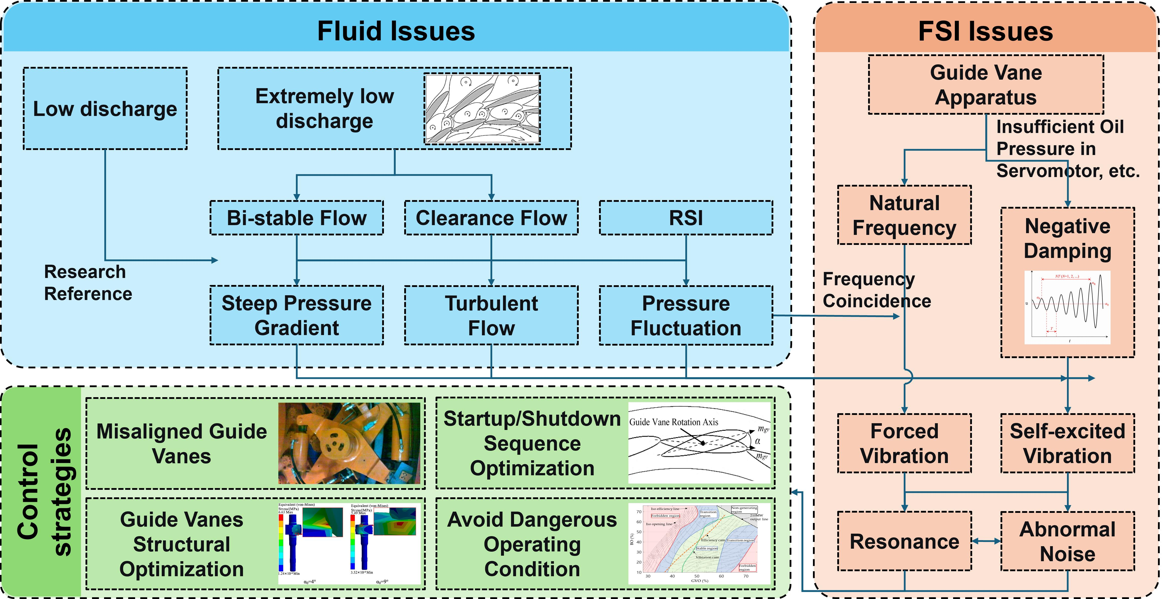
Graphical Abstract

1. Introduction

In recent years, against the global backdrop of climate change, renewable energy industries such as photovoltaic and wind power have developed rapidly. However, the intermittency and volatility of renewable energy pose serious challenges to grid stability [1]. In 2025, a major blackout occurred in Spain [2]. In India, because renewable energy has undertaken a large share of the load, the net load shows a deep valley at noon and then rises sharply in the evening [3]. These cases demonstrate the critical importance of grid stability to national welfare and the economy, and indicate that energy storage is essential for maintaining grid stability [4].
As the most technologically mature and widely deployed green regulating power source, PSH plays an irreplaceable role in balancing fluctuations in wind and solar power and ensuring the safe and stable operation of the grid [5,6,7]. Pumped storage units are characterized by high rotational speed, bidirectional operation, and complex dynamic characteristics [8]. Under the demand for deep peak regulation, pumped storage units are started and stopped frequently, with daily start-up/shutdown cycles reaching several times or even dozens of times [9,10]. During unit start-up and shutdown, the unit inevitably passes through the near-zero flow condition under pump mode [11].
The near-zero flow condition under pump mode may occur in various transient processes, but it most commonly appears during the transition from Pumping Condenser Mode (SCP) to Pumping Operation (PO). This is because the unit always undergoes the SCP-to-PO process when transitioning from a standstill state or other operating conditions to pump mode. Figure 1 presents the time-varying curves of guide vane opening, rotational speed, absorbed power, and ball valve opening during the SCP-to-PO process of a pumped storage unit.
When a pump turbine passes through the near-zero flow region, its operating condition deviates significantly from the optimal design condition. The internal flow field exhibits strongly unsteady flow characteristics, which readily induce various hydraulic and structural instability problems [12,13,14]. At the hydraulic level, these problems are mainly manifested as intense pressure fluctuation, internal flow, cavitation, and other phenomena [15,16,17]. Such unstable flow features are further exacerbated during the transient start-up and shutdown processes of the unit [18,19,20]. At the structural level, unsteady hydraulic excitation further induces a series of engineering problems, including vibration and noise [21,22,23]. These phenomena not only severely constrain the reliable operation of the unit but also endanger equipment structural safety and reduce the economic benefits of power station operation.
The near-zero flow condition is often regarded as a “danger zone” for unit stability. Therefore, most start-up procedures are designed to pass through this region as quickly as possible. Table 1 summarizes representative studies on instability phenomena under near-zero flow pump mode conditions.
Table 1. Studies on instability phenomena under near-zero flow pump mode conditions.
StudyAuthorsYearConcise Issue
YiXing Pump-Turbine guide vane vibrations: problem resolution with advanced CFD analysis [24]Nennemann, B. et al.2010Guide vane vibration induced by amplified von Karman vortices, bi-stable attached flow, and torsional self-excited vibration.
Self-excited vibration of the Guide Vane Mechanism of the Jiangsu Yixing Pumped Storage Power Station Pump-Turbine [25]Li, Q.Z. et al.2011Abnormal vibration of the guide vane mechanism, resulting in component damage.
Assessment of guide vane self-excitation stability at small openings in pump flow [26]Nennemann, B. et al.2013Guide vane self-excited instability and potential divergence at high reduced velocity.
Resonance investigation of pump-turbine during startup process [27]He, L.Y. et al.2014Start-up resonance caused by RSI-induced hydraulic excitation matching the runner natural frequency.
Pressure fluctuations in the vaneless space of high-head pump-turbines: A review [28]Zuo, Z.G. et al.2015Severe pressure fluctuation in the vaneless space, leading to vibration and fatigue failure.
A review of rotating stall in reversible pump turbine [29]Zhang, Y.N. et al.2017Rotating stall causing large-amplitude pressure fluctuation, passage blockage, and strong backflow.
Three-dimensional transient simulation of a prototype pump-turbine during normal turbine shutdown [30]Li, Z.J. et al.2017Flow separation and vortex structures at reduced guide vane opening, intensifying runner force fluctuations and bearing thrust load.
Numerical investigation of the flow regime and cavitation in the vanes of reversible pump-turbine during pump mode’s starting up [31]Tao, R. et al.2019Submerged jets between guide vanes causing local pressure drops, jet-vortex cavitation, and cavitation near guide vane edges.
Analysis and research on back-to-back startup failure of pumped storage units [32]Yang, M.Z. et al.2021Back-to-back start-up failure, with causes and mitigation measures identified.
Analysis and treatment of abnormal noise during pump mode startup of a pumped storage power station [33]Yang, H.L. et al.2023Abnormal whistling during pump mode start-up caused by side-clearance leakage jet under vaneless space pressure buildup.
Analysis of pressure fluctuation during low-head startup of pumped storage units [34]Chen, H.X. et al.2023Low-head start-up instability dominated by RSI, large-scale vortices, and evolving draft-tube vortex rope.
Research on hydraulic characteristics of Pump-Turbine during startup process [35]Huang, W.L. et al.2023Severe start-up pressure fluctuations associated with a high-speed water ring, complex runner-passage vortices, and torque reduction.
Investigations into Hydraulic Instability during the start-up process of a Pump-Turbine under low-head conditions [36]Wang, T.Z. et al.2024Low-head start-up instability caused by vortex shedding, water hammer effects, S-characteristic entry, and dual-layer vortex rope formation.
Pulsation stability analysis of a prototype Pump-Turbine during Pump Mode startup: Field test observations and insights [37]Xia, M. et al.2024Prototype tests revealed a transition from forced vibration to self-excited vibration and anomalous draft-tube surging frequency.
Hidden hydraulic instability: Clearance Flow dynamics during Pump-Turbine Pump Mode startup [38]Xia, M. et al.2025End-wall clearance flow amplified flow instability through Coanda-induced leakage vortices, affecting hydraulic thrust and guide vane hydraulic torque.
Startup process of pumped storage unit for avoiding S-Shaped Region based on geometric perspective method [39]Yuan, X. et al.2025Speed overshoot caused entry into the S-characteristic region and triggered start-up failure.
To address these problems, researchers and engineers have widely adopted methods such as model tests, prototype tests, Computational Fluid Dynamics (CFD), and Finite Element Analysis (FEA) to investigate the mechanisms of hydraulic instability and the laws of vibration response under near-zero flow conditions [40,41]. Targeted regulation and optimization measures for stability improvement have also been explored [42]. Based on field validation from many actual high-head pumped storage power station cases, the theoretical system for instability characteristics and the engineering prevention and control schemes have been gradually improved [43,44].
Detailed information on pumped storage power stations where near-zero flow instability has occurred is summarized in Table 2. The data in Table 2 are sourced from the Development Report of Pumped Storage Industry, which is available on the official website of the China Renewable Energy Engineering Institute [45].
Regarding the dominant mechanism of instability under near-zero flow conditions, controversy remains in the academic community. Some studies suggest that forced vibration induced by RSI is the main cause, whereas others indicate that the feedback loop between clearance flow and the guide vane structure may induce self-excited vibration [17,24,26]. The latter has attracted increasing attention because it can better explain the randomness and non-repeatability observed in field cases. At present, no unified theoretical framework has been established for the dominant mechanism of instability under near-zero flow conditions.
Accordingly, this review systematically summarizes existing studies from two dimensions: Hydraulic instability characteristics and structural vibration instability characteristics under near-zero flow conditions in pump mode. It clarifies the causes of instability, reviews recent research progress and control measures, and provides a reference for stable-operation optimization and engineering design of pumped storage units in the near-zero flow region.

2. Fluid Issues

2.1. Fluid Challenges

During unit start-up process, shutdown process, and operating condition transition, the internal flow is highly prone to instability because the flow rate deviates from the design condition and the velocity distribution in the flow passage becomes nonuniform [46,47]. This phenomenon is particularly pronounced under the near-zero flow condition in pump mode, especially in high-head pumped storage units, where markedly intensified pressure fluctuation and unsteady flow structures are often observed [31,48,49].
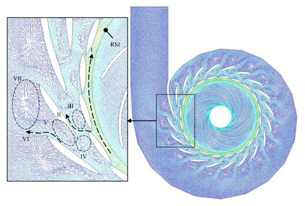
Under the near-zero flow condition in pump mode, three major instability sources exist inside the unit [29,30,50]: local vortex structures formed by clearance leakage flow, bi-stable flow, and excitation induced by RSI. Figure 2 illustrates these three flow phenomena. At small openings, the mismatch between the inflow angle and the guide vane setting can induce flow separation and vortex structures [51]. Meanwhile, the larger pressure difference across clearances under small openings strengthens leakage through the end-wall and side clearances, forming local unstable structures such as leakage vortices [52]. In addition, nonuniform inflow and complex vortex structures intensify the unsteady flow interaction between the runner and the guide vanes, thereby further amplifying RSI excitation and the induced pressure fluctuations [53].
These instability sources not only increase hydraulic loss and reduce energy-conversion efficiency, but also induce intense pressure fluctuations, vibration response, and structural fatigue loads. In high-head pumped storage units, such flow instabilities may further amplify operational risks during the start-up process, shutdown process, and operating condition transition, thereby limiting the safe operating range of the unit [54,55].
Unlike conventional off-design operating conditions, the near-zero flow condition in pump mode is a transient state during an operating condition transition and usually exists for only a short duration. Its instability characteristics are governed by the coupled action of multiple flow mechanisms rather than by a single dominant phenomenon. Therefore, understanding the evolution and interaction mechanisms of these flow instabilities has become a major focus of recent research [56].
Figure 2. Chaotic internal flow under near-zero flow conditions in pump mode [57].
Machines 14 00820 g002

2.2. Research Progress in Hydraulic Instability

2.2.1. Research Methods in the Fluid Field

(1)
Experimental Methods in the Fluid Field
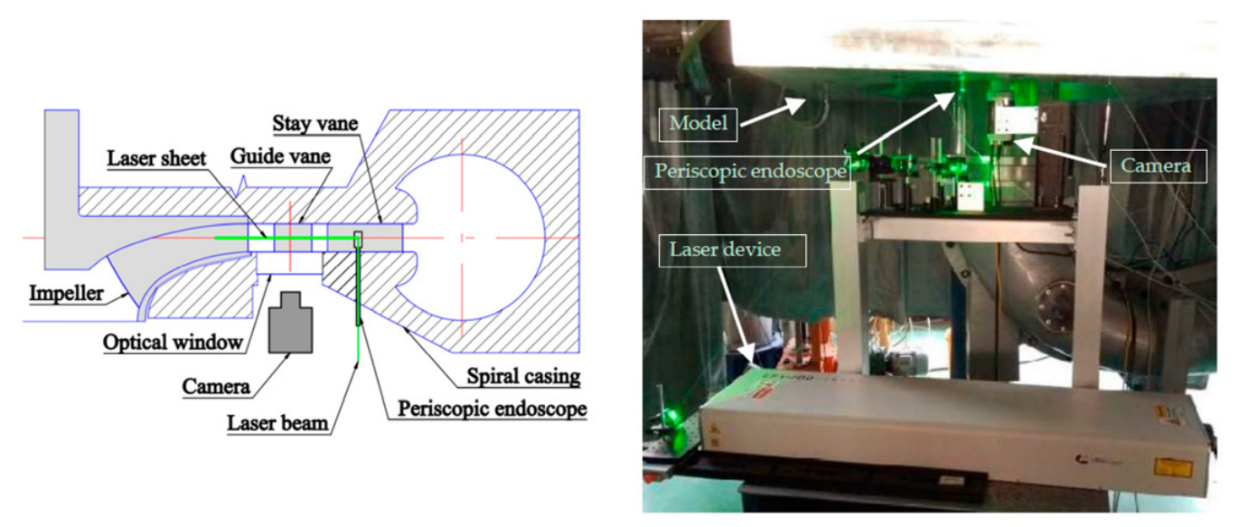
Experimental investigation is still the most direct method for identifying internal flow structures in pump turbines under near-zero flow conditions. Particle Image Velocimetry (PIV) has been widely used in pump turbine model tests. It is usually applied in optically accessible regions, such as the guide vane passages, vaneless space, runner inlet/outlet region, and draft-tube cone [51,58,59,60,61]. To obtain reliable flow-field information, transparent model components, suitable seeding particles, phase-locked image acquisition, and synchronized pressure measurements are often required. For example, PIV has been used to measure the transient flow field in the guide vane region of pump turbines in pump mode and to clarify the evolution of rotating stall [51]. It has also been applied to high-head pump turbine models and vaneless-space flow measurements [60,61,62]. As shown in Figure 3, a typical PIV system introduces a laser sheet into the selected measurement plane and records the motion of seeded particles with a high-speed camera. This configuration enables planar velocity-field reconstruction and is suitable for visualizing coherent flow structures in pump turbine passages.
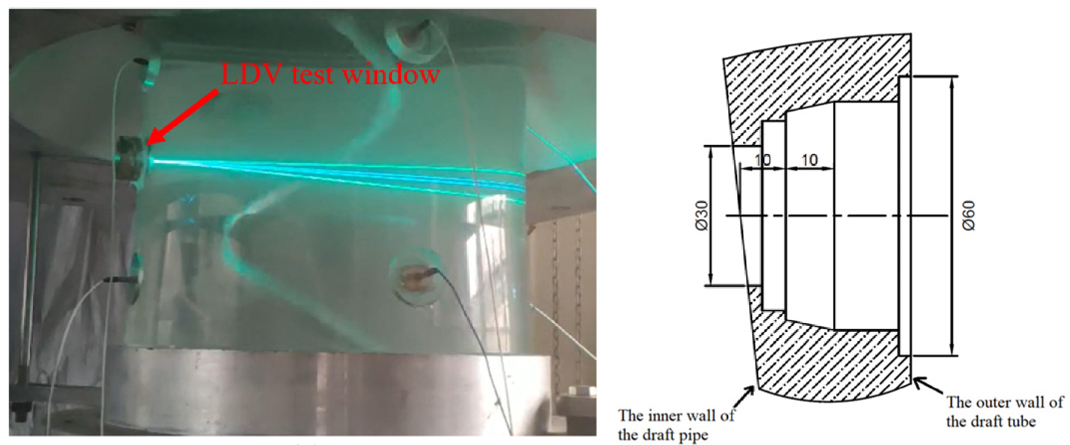
Compared with PIV, Laser Doppler Velocimetry (LDV) provides non-intrusive and high-precision pointwise velocity measurements. It is especially suitable for measuring axial and circumferential velocity distributions in confined regions, such as the draft tube [62,63,64]. In pump turbine studies, LDV is often combined with pressure pulsation measurements. This makes it possible to relate local velocity fluctuations to draft-tube vortex motion and pressure instability [62,63]. As illustrated in Figure 4, LDV measures the velocity of tracer particles passing through the intersection of laser beams at a local measurement volume. Therefore, it can provide accurate local velocity information without disturbing the internal flow field, although repeated measurements are usually required to obtain spatial distributions.
However, model tests are still limited by scale effects, restricted optical windows, and sparse measurement locations. These limitations make it difficult to fully resolve three-dimensional unsteady flow structures under near-zero flow conditions. They also highlight the advantages of CFD methods in resolving complex three-dimensional unsteady flow structures under such conditions.
Figure 3. Schematic diagram of PIV setup [51].
Machines 14 00820 g003
Figure 4. Schematic diagram of LDV setup [63].
Machines 14 00820 g004
(2)
CFD Methods
CFD has become a principal tool for studying complex flow instabilities in pump turbines under near-zero flow conditions. Under these operating conditions, strong flow separation, clearance leakage vortices, backflow, and runner–stationary component interactions are often present. Therefore, conventional steady Reynolds-Averaged Navier–Stokes (RANS) methods are usually insufficient for resolving strongly unsteady flow structures. Unsteady RANS (URANS) methods are more widely used because they can capture time-dependent pressure pulsations and large-scale vortex evolution with acceptable computational cost [51].
For more complex unsteady flow phenomena, high-fidelity turbulence-modeling methods, such as Large Eddy Simulation (LES) and Detached Eddy Simulation (DES), have been increasingly adopted [65]. These methods are more suitable for resolving multiscale vortex structures, rotating stall, and low-frequency flow dynamics. In pump turbine simulations, sliding-mesh techniques, appropriate near-wall treatment, grid-independence verification, and sufficiently small time steps are also essential for accurately capturing rotor–stator interaction and transient pressure fluctuations. Therefore, CFD provides an important complement to model tests, especially when three-dimensional unsteady flow structures are difficult to fully measure under near-zero flow conditions.

2.2.2. Clearance Flow

The guide vane end-wall clearance and side clearance are important factors affecting the hydraulic performance and flow stability of reversible pump turbines [66]. Early studies mainly focused on clearance size, leakage loss, and efficiency degradation. Recent studies have further shown that clearance-induced flow structures may also contribute to low flow instability and transient hydraulic response [67,68,69].
The basic mechanism of clearance flow is pressure-driven leakage. Studies [70] show that the pressure difference across the guide vane drives leakage flow through the clearance. This leakage flow interacts with the main flow and generates complex vortex structures. These structures increase turbulence generation and energy dissipation, and may further disturb the flow organization in the guide vane and runner passages. This effect becomes more significant under near-zero flow conditions. As the guide vane opening decreases, the leakage flow accounts for a larger proportion of the total flow rate. Meanwhile, the high pressure difference across the clearance strengthens the leakage jet [38].
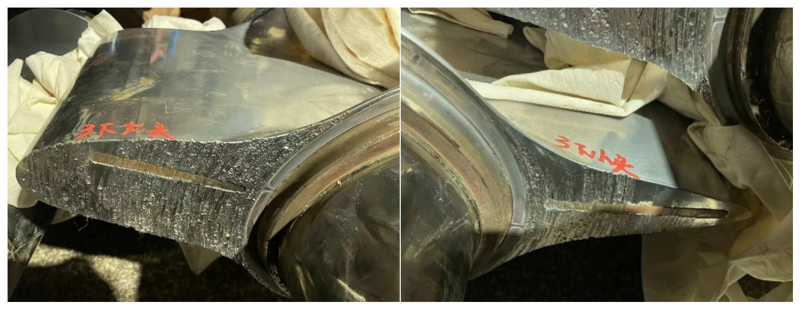
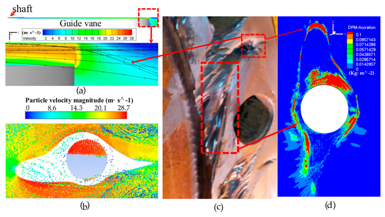
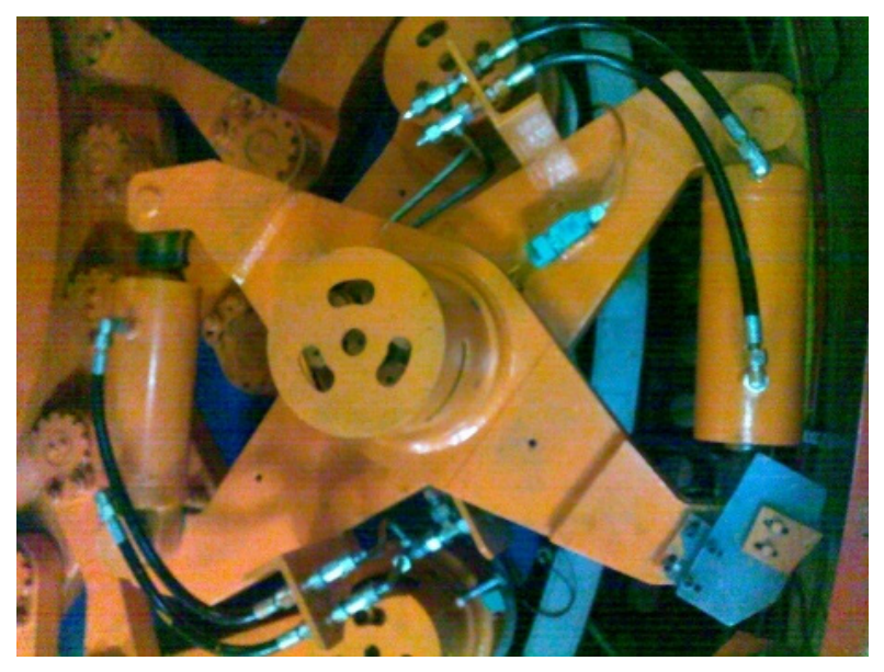
The characteristics of clearance flow are also strongly affected by local geometric details. These include the upper and lower end-wall clearance height, the presence of wear-resistant copper strips, and the size of the copper strips [38,71]. Figure 5 shows a typical end-face wear of guide vanes and copper strips observed in engineering practice. The wear pattern indicates that the clearance region is subjected to strong local shear, leakage-flow impact, and nonuniform hydraulic loading. Figure 6 further shows the complex three-dimensional flow near the guide vane end surface. The comparison between local flow structures, particle velocity in the clearance, wear morphology, and DPM accretion indicates that clearance leakage flow is closely related to local erosion and wear patterns.
Field observations also support the importance of clearance-induced instability. During the pump mode start-up process of Unit 1 at the J station, significant increases in the horizontal and vertical vibration of the upper frame were observed when the unit operated under the splash-power condition, which corresponds approximately to zero-flow operation [72]. Subsequent studies showed that the abnormal hydraulic excitation was closely related to the interaction between clearance leakage flow and the main flow [73]. Pressure measurements below the top cover also showed evident pressure fluctuations during guide vane opening and pump mode establishment [74,75].
In summary, under near-zero flow conditions, clearance flow is no longer only a leakage-loss problem. Because of the combined effects of small guide vane opening and high pressure difference, it may become a key factor affecting flow-field organization, pressure fluctuation, and transient stability.
Figure 6. Comparison of wear morphology and flow field on the end-surface of the head cover [76]: (a) Flow field at the leading edge of guide vane airfoil (XZ section); (b) particle velocity in the clearance; (c) wear morphology; and (d) DPM accretion. Complex flow pattern in the Guide Vane side clearance.
Machines 14 00820 g006

2.2.3. Bi-Stable Flow

As understanding of the flow mechanisms under small openings has deepened, researchers have gradually found that instability in the guide vane region is associated with bi-stable flow characteristics. Early research by Pulpitel et al. [77] reported that guide vanes may undergo self-excited vibration under small openings and suggested that this behavior is closely related to the flow state within the guide vane clearance. On this basis, Nennemann et al. [24] conducted unsteady flow CFD studies on abnormal guide vane vibration in a pumped storage power station and identified obvious bi-stable flow under small openings in pump mode.
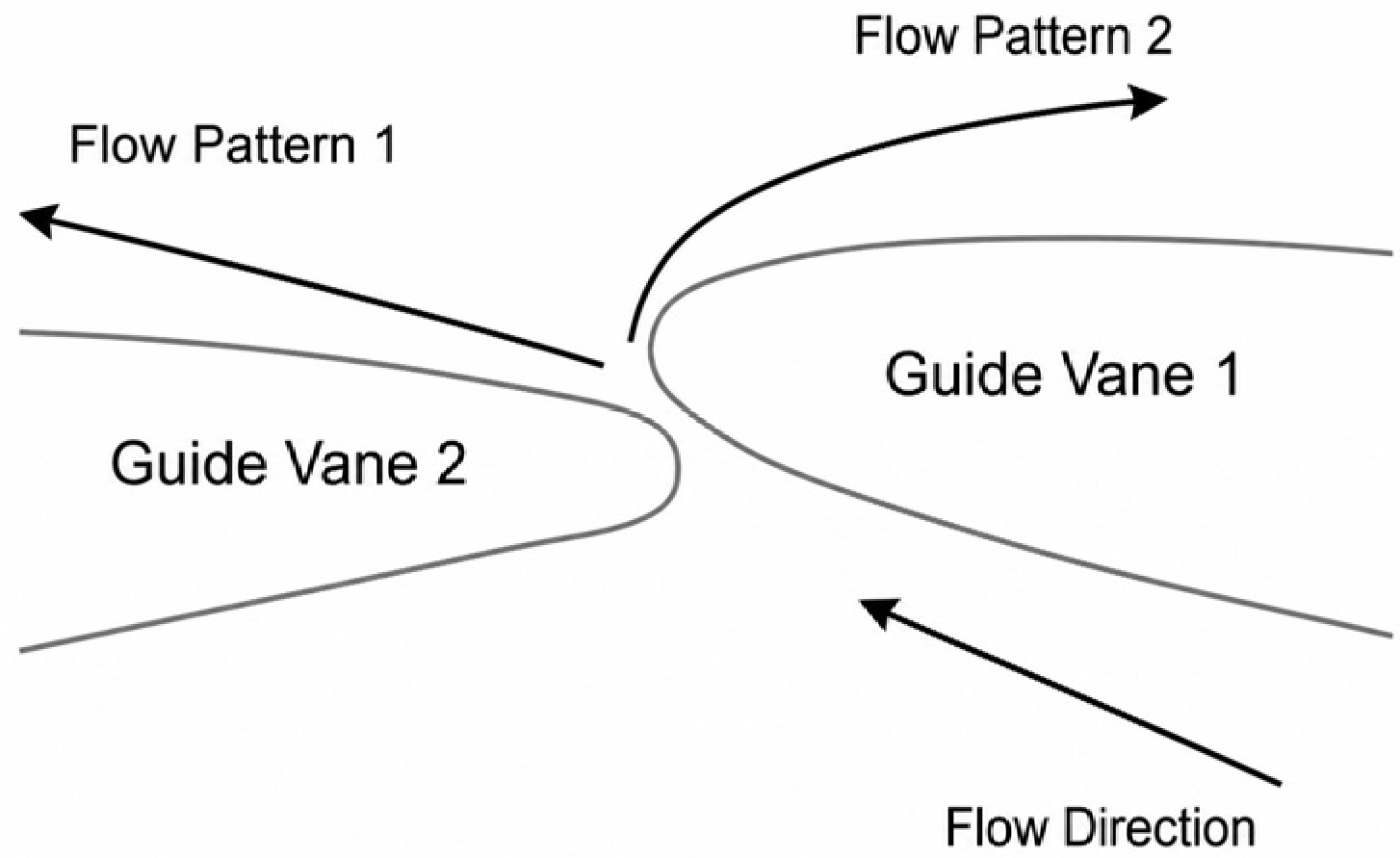
The results show that, under extremely small openings in pump mode (less than 0.5°), the leakage jet between guide vanes may form two distinct stable attached flow states [78]: one attached to the leading-edge side of the adjacent guide vane, and the other attached to the guide vane trailing-edge side under the Coanda Effect, as shown in Figure 7. Both flow states can remain relatively stable, but the corresponding guide vane hydraulic torque differs markedly. When a guide vane undergoes slight elastic deformation, the flow field may switch between the two attachment modes, causing a sudden change in hydraulic torque and forming positive feedback that ultimately induces guide vane self-excited vibration. Numerical simulations show that when the guide vane opening decreases to below approximately 0.3°, vibration instability induced by switching between bi-stable attached flow modes may occur.
Therefore, bi-stable flow is a significant flow feature under extremely small openings in pump mode and can induce hydraulic instability. The guide vane trailing-edge geometry, clearance length, and switching characteristics of the attached flow state are all considered important factors affecting this flow feature [79].

2.2.4. RSI-Induced Pressure Fluctuations

RSI is regarded as a major source of pressure fluctuation in the guide vane region of high-head pump turbines [80]. It is caused by flow interference between rotating components, namely the runner or rotor; and stationary components, namely guide vanes or stators [81]. In a pump turbine, when the runner rotates, the relative motion between the runner blade outlet and the guide vane generates periodic pressure fluctuations in the flow field. The dominant frequency is usually the Blade Passing Frequency (BPF) and its harmonics [82,83].
The excitation frequency imposed by the guide vanes on the runner due to RSI can be expressed as:
f g = Z g × f r
where Z g is the number of guide vanes and f r is the rotational frequency.
The excitation frequency imposed by the runner on stationary components such as guide vanes corresponds to the BPF:
f b = Z r × f r
where Z r is the number of runner blades and f r is the rotational frequency.
The number of nodal diameters k of the excitation pattern generated by RSI is:
n Z g ± k = m Z r
where Z g is the number of guide vanes, Z r is the number of runner blades, k is the number of nodal diameters of the excitation mode, and m and n are positive integers.
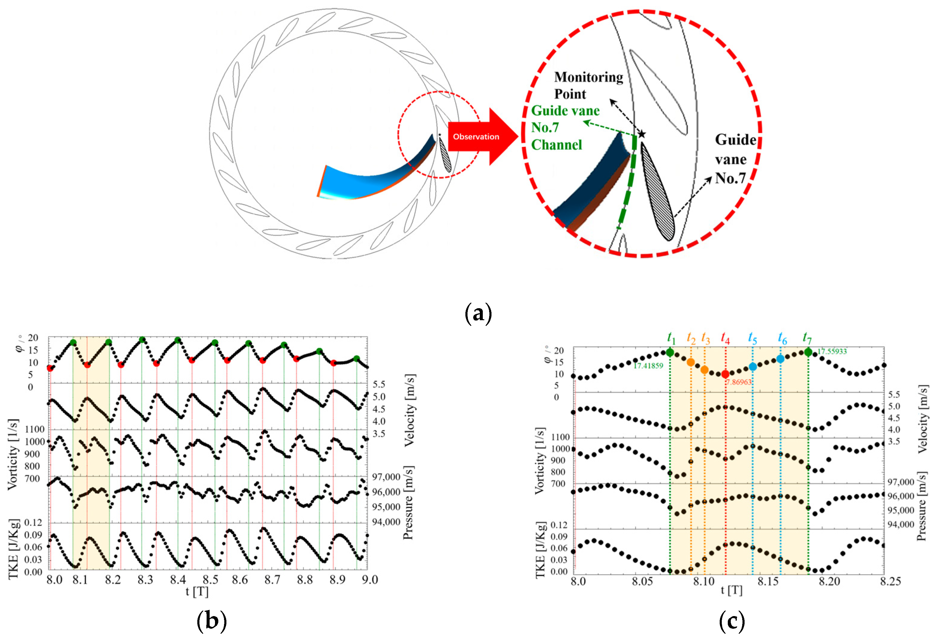
As shown in Figure 8, RSI-induced pressure fluctuation can be identified through monitoring points arranged in the runner–guide vane interaction region. The pressure responses at these points exhibit clear periodic characteristics.
The RSI-induced pressure fluctuation frequency may act as the hydraulic excitation frequency responsible for forced vibration of pump turbines under near-zero flow conditions in pump mode [84]. Existing studies also indicate that RSI may be one of the causes of instability in certain power stations under near-zero flow conditions in pump mode [85].
Figure 8. Flow field parameters under RSI [85]: (a) RSI monitoring-point section; (b) RSI response at the monitoring points; (c) enlarged view of one RSI cycle in the yellow-highlighted region of panel (b).
Machines 14 00820 g008

2.3. Summary of Fluid Issues

The literature reviewed in this section shows that the flow field under near-zero flow conditions in pump mode is characterized by strong unsteady flow, intense pressure fluctuations, and multiple interacting instability mechanisms. Clearance leakage flow, bi-stable flow, and RSI-induced pressure fluctuations have all been identified as potential contributors to hydraulic instability. Nevertheless, most existing studies focus primarily on flow phenomena themselves, whereas the subsequent transmission of hydraulic excitation to structural vibration and noise generation remains less understood. Therefore, investigating the FSI mechanisms associated with these hydraulic instabilities has become an important research direction.

3. FSI Issues

3.1. FSI Challenges

3.1.1. Vibration Problems

Under near-zero flow conditions in pump mode, hydraulic instability can induce serious structural vibration problems through the FSI mechanisms [86].
When the frequency of unsteady flow-induced hydraulic excitation approaches the natural frequency of components in the guide vane mechanism, the system can easily enter a resonance-amplification state, leading to a sharp increase in vibration intensity. This flow-induced vibration is manifested not only as persistent abnormal noise, but may also cause severe consequences such as connecting-pin detachment, friction-plate sliding, component collision, and even structural damage [24,26,87,88,89].
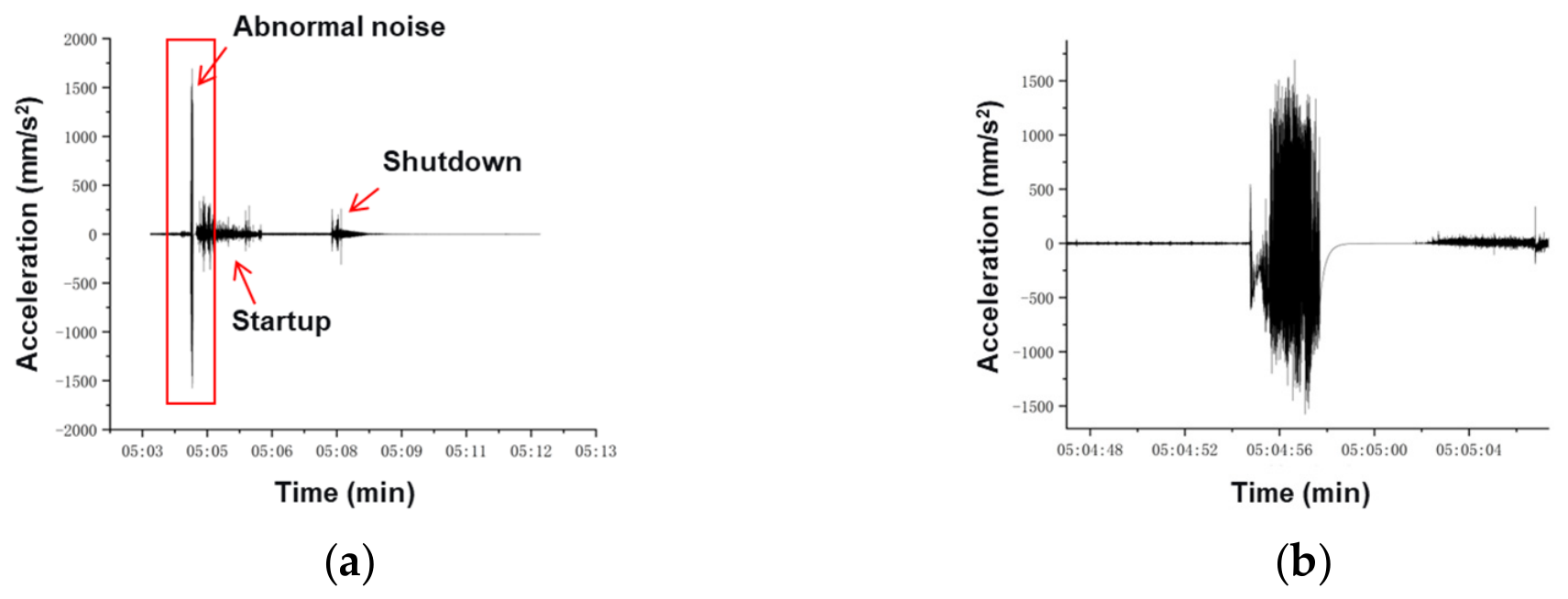
Engineering practice shows that, during variations in guide vane opening, a positive feedback mechanism can readily form between clearance leakage flow and guide vane torsional vibration. As a result, the energy of pressurized water is continuously transferred into the structural system, sustaining the development of self-excited vibration [25]. Monitoring data indicate that, under resonance conditions, the vibration velocity of key components such as the top cover can reach approximately 200 mm/s, which significantly exceeds conventional safety thresholds. As shown in Figure 9, the vibration acceleration during the abnormal-noise event increases sharply within a short time, indicating a strong transient vibration response of the guide vane lever arm under resonant conditions.

3.1.2. Abnormal Noise Problems

Under near-zero flow conditions in pump mode and during operating condition transition, hydraulic instability can induce serious abnormal noise and noise problems through FSI mechanisms. Operating experience from multiple pumped storage power stations indicates that this phenomenon is widespread and becomes more prominent under high-head conditions.
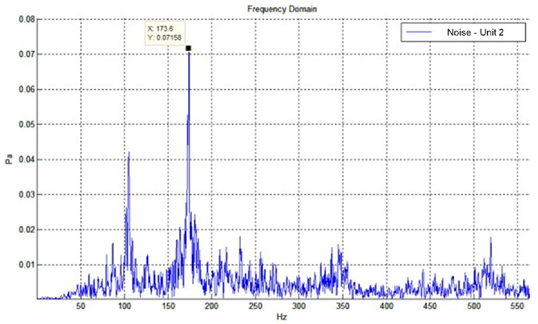
From the perspective of frequency-domain characteristics, abnormal noise signals usually appear as broadband components [72] or specific discrete frequencies [90]. As shown in Figure 10, the audio frequency analysis during resonance can identify the dominant frequency components of abnormal noise and reveal their temporal evolution. These frequencies often coincide with the vibration frequencies of key components such as the guide vane shaft. This indicates that their nature is closely related to resonance or self-excited vibration. Abnormal noise usually occurs at two stages: the instant of guide vane opening and the instant of guide vane closing. Under these conditions, unstable flow patterns can generate periodic pressure fluctuations. When the excitation frequency approaches the natural frequency of components in the guide vane mechanism, structural resonance is triggered and intense noise is radiated. Field monitoring data show that the noise intensity associated with abnormal noise can exceed 140 dB. It may also cause secondary damage, such as the detachment of servomotor measurement and protection components, posing significant threats to unit operational safety and the on-site working environment.

3.2. Research Progress of FSI

3.2.1. Research Methods in the FSI Field

(1)
Experimental Methods in the FSI Field
For pump turbines operating under near-zero flow conditions, experimental research remains the most direct route for understanding FSI phenomena [91,92,93]. Early studies mainly relied on monitoring systems installed in hydropower stations. Limited by sensor type, sampling frequency, and measurement location, the available information was generally restricted to partial components, such as top-cover vibration, shaft runout, and guide-bearing vibration. Therefore, identifying the transmission path between hydraulic excitation and structural response was often difficult.
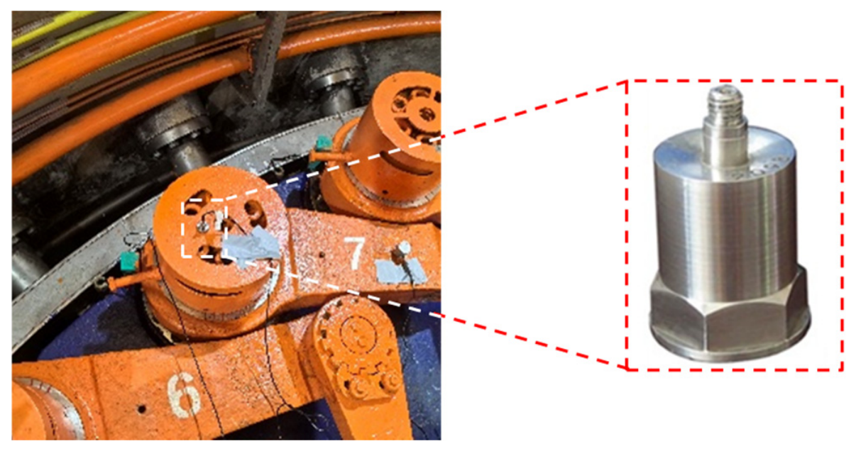
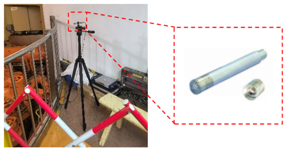
With the rapid development of measurement technology, experimental research has gradually evolved toward multisource synchronous measurement. Modern testing systems widely use high-sensitivity acceleration sensors, microphone arrays, dynamic pressure sensors, displacement sensors, and strain gauges [94]. As shown in Figure 11, acceleration sensors can be arranged at key structural locations to capture vibration responses during transient operating conditions. Figure 12 further shows the arrangement of sound pressure sensors, which can be used to identify the spatial and temporal characteristics of abnormal noise. These instruments can synchronously capture hydraulic response, structural response, and acoustic response.
Significant progress has also been made in measurement methods. In addition to traditional efficiency-evaluation methods based on hydraulic parameters, the thermodynamic method, which uses the small temperature difference between the inlet and outlet of a unit, has been increasingly applied to prototype efficiency tests [95]. Its principle is to directly calculate efficiency according to the first law of thermodynamics using millikelvin-level temperature differences between the inlet and outlet of hydraulic machinery, and it provides very high accuracy. FSI experimental methods have also become more refined. For example, one study successfully captured the strong coupling between guide vane vibration and surrounding unsteady flow through multisource synchronous measurements using semiconductor strain gauges, a laser vibrometer, piezoresistive pressure sensors, and an underwater nonintrusive pulse-excitation system [96].
A third important advance is the substantial improvement in sampling frequency and time resolution. Modern acquisition systems can achieve sampling frequencies of several kilohertz or even above 10 kHz [97]. This improvement enables the identification of higher-frequency hydraulic excitation, structural response, and transient vibration events during start-up process, shutdown process, and operating condition transition [98].
(2)
FSI Methods
With the development of computational techniques, high-accuracy FSI numerical methods have become effective tools for revealing the mechanisms of complex flow and structural response in pump turbines under near-zero flow conditions in pump mode, and their computational accuracy and engineering credibility continue to improve [99]. At present, coupled solution strategies combining the Finite Element Method and CFD can effectively capture the interaction between flow field excitation and structural vibration and can obtain results that agree well with field measurements under prototype conditions. In studies of several high-head power stations, the applicability of numerical methods and experimental techniques in prototype environments has been fully verified, enabling accurate identification of instability mechanisms and validation of control schemes [44]. For the stress evolution of guide vanes during operating condition transition, FSI calculations can accurately identify stress-concentration regions and their dynamic distribution, providing high-resolution evidence for determining structural weak points [86]. These advances indicate that FSI numerical methods are shifting from auxiliary validation tools toward independent and reliable mechanistic research tools, laying a solid foundation for deeply understanding and suppressing flow-induced vibration under near-zero flow conditions in pump mode.

3.2.2. Forced Vibration

Forced vibration is one of the most widely adopted frameworks for explaining abnormal vibration in hydraulic machinery. Early studies mainly attributed resonance problems in pump turbines to periodic hydraulic excitation generated by RSI [100]. It is generally believed that pressure fluctuations induced by the interaction between runner blades and guide vanes contain distinct excitation frequencies, including the BPF, guide vane passing frequency, and their harmonics. When these hydraulic excitation frequencies approach the natural frequency of hydraulic structures, resonance may occur, resulting in amplified vibration response [101].
Based on this mechanism, extensive studies have been conducted on the runner, top cover, stay vanes, and guide vanes [27,102]. Studies further demonstrated that RSI-induced pressure fluctuations can significantly affect the dynamic behavior of hydraulic structures, especially in high-head pump turbines where the amplitude of pressure fluctuation is relatively large [103,104,105,106]. To avoid resonance risk, modal analysis and Campbell diagram-based evaluation have become routine procedures during the modern design stage of pump turbines [107].
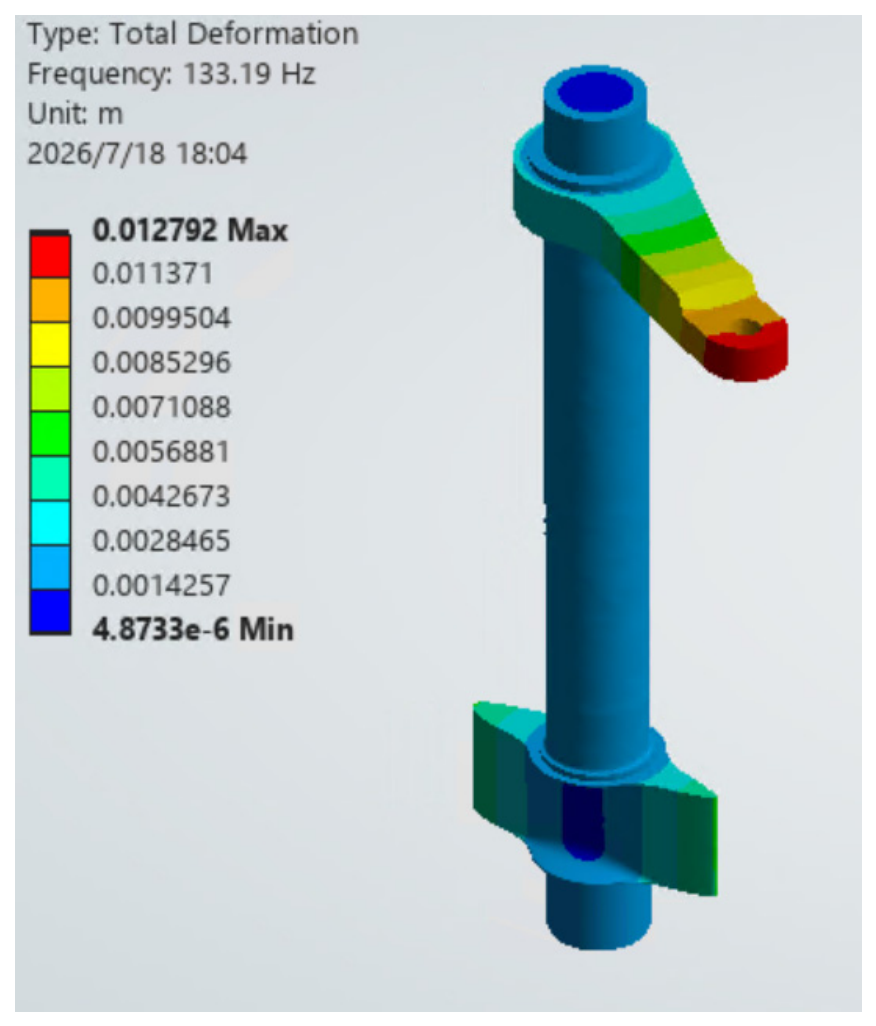
In recent years, research attention has expanded from the runner to the guide vane system. Existing studies show that guide vane vibration is governed by both hydraulic excitation and structural modal characteristics, including bending and torsional modes. When the RSI-induced excitation frequency coincides with the natural frequency of the guide vane shaft, operating mechanism, or support structure, as shown in Figure 13, resonance-type forced vibration may occur.
However, existing evidence indicates that forced vibration should be regarded as a possible explanation rather than a deterministic mechanism for all guide vane vibration events. Many field observations show that vibration and abnormal noise under near-zero flow conditions often exhibit strong randomness and poor repeatability [108]. Therefore, recent studies increasingly suggest that mechanisms other than classical forced resonance may also be involved [79,109,110]. These issues have motivated further investigation into self-excited vibration mechanisms, which are discussed in the following section.

3.2.3. Self-Excited Vibration

In recent years, self-excited vibration has attracted increasing attention as a potential mechanism for explaining abnormal vibration and abnormal noise in pump turbines under near-zero flow conditions [108]. Unlike forced vibration driven by a specific external excitation frequency, self-excited vibration originates from an energy-feedback process between the flow field and the structure. When fluid forces can continuously input energy into structural vibration and overcome system damping, vibration may continue to develop and be sustained even in the absence of an external periodic excitation corresponding to the structural natural frequency [111].
The growing interest in self-excited vibration mainly originates from field observations that cannot be fully explained by conventional resonance theory. In many pumped storage power stations, severe vibration and abnormal noise are observed only under small openings and specific transient operating conditions [78]. Moreover, the same start-up process does not necessarily produce the same vibration response. This randomness and poor repeatability are difficult to reconcile with classical resonance phenomena.
Researchers believe that guide vane clearance flow plays a key role in the development of self-excited vibration. Under near-zero flow conditions, the pressure difference across the two sides of a guide vane increases significantly, thereby strengthening leakage jets through the end-wall and side clearances [112]. The resulting unsteady flow structures may generate fluctuating forces and hydraulic torque on the guide vane.
When a guide vane undergoes torsional or axial motion, the clearance geometry and leakage-flow pattern change simultaneously, which in turn modifies the hydraulic load acting on the structure [113]. This feedback process enables hydraulic energy to be continuously transferred into the vibration system and may ultimately lead to self-excited oscillation.
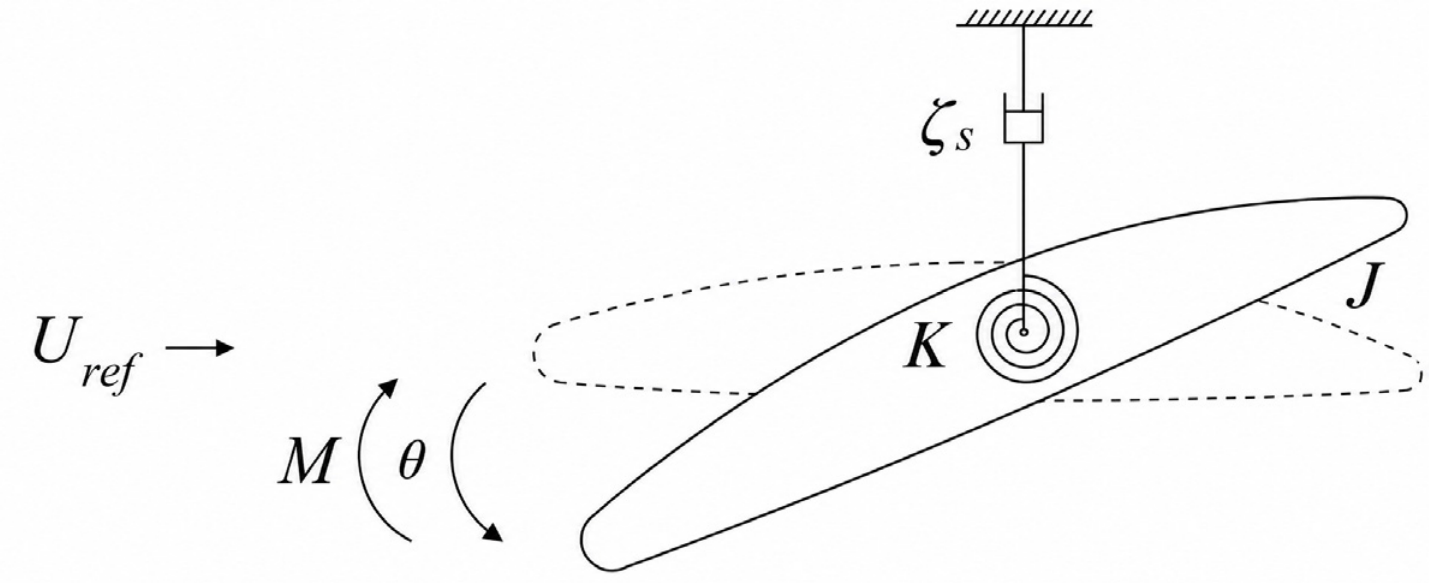
Taking the guide vane torsional-vibration model shown in Figure 14 as an example, the governing equation can be expressed as:
θ ¨ + ζ s θ ˙ + ω 1 2 θ = M J
where θ is the guide vane torsional angle, ζ s is structural damping, ω 1 is the natural frequency of the guide vane torsional mode, M is the hydraulic torque, and J is the guide vane rotational inertia.
For small-amplitude vibration, the hydraulic torque can be regarded as a function of the torsional angle and linearized near the equilibrium position. The equivalent stiffness of the system can then be expressed as the superposition of structural stiffness and hydrodynamic stiffness, and its stability depends on the relative magnitude of the two. When the following condition is satisfied:
M θ 0 > K
The equivalent negative stiffness generated by hydrodynamic feedback exceeds the structural restoring stiffness, and the system loses static stability and enters an unstable state [111].
This criterion indicates that self-excited vibration does not necessarily depend on an external periodic excitation frequency, but may instead be directly triggered by feedback between the flow field and the structure. For the guide vane system under near-zero flow conditions, when strong clearance jets, local backflow, and unsteady vortex structures make the hydraulic torque highly sensitive to guide vane displacement, the above instability condition may be satisfied [114]. Therefore, self-excited vibration is regarded as one of the important candidate mechanisms for explaining severe guide vane vibration and abnormal noise in some pumped storage units. However, direct experimental and FSI evidence for guide vane self-excited vibration under near-zero flow conditions remains limited, and its specific formation process and relationship with field abnormal noise require further investigation.

3.3. Summary of FSI Issues

The studies reviewed in this section demonstrate that hydraulic instabilities occurring under near-zero flow conditions in pump mode can be effectively transmitted to guide vane structures through FSI mechanisms. Two main competing mechanisms have been proposed to explain abnormal vibration and noise events: forced vibration induced by hydraulic excitation, and self-excited vibration sustained by fluid–structure interaction feedback. While a unified mechanism has not yet been established, existing research increasingly points to flow-induced vibration as the fundamental cause of these phenomena. Therefore, identifying the dominant hydraulic excitation sources and clarifying their interaction with guide vane dynamics remain key challenges for future investigations.

4. Control Strategies

4.1. Misaligned Guide Vanes

MGV refers to an operating strategy in which not all guide vanes open completely synchronously during pump turbine operation; instead, the opening angle or opening speed of some guide vanes differs from that of others [115]. Conventional guide vane control generally requires all guide vanes to move synchronously around the runner to form a circumferentially symmetric flow field. By contrast, MGV intentionally breaks this circumferential symmetry and introduces asymmetric flow structures in the vaneless space and runner inlet, thereby changing the development of local jets and vortices [18,41,116,117,118]. As shown in Figure 15, a typical MGV structure is characterized by nonuniform guide vane openings around the circumference, which directly modifies the circumferential flow distribution entering the runner.
Existing studies show that the MGV strategy is highly effective in suppressing unstable flow under low flow conditions [119,120]. Both CFD calculations and experimental studies indicate that asymmetric guide vane opening can effectively weaken large-scale vortex structures between guide vanes, alleviate flow separation and backflow reducing pressure fluctuation, vibration, and noise levels [116]. During transient processes such as start-up, nonsynchronous guide vane opening can gradually stabilize the internal flow while reducing pressure fluctuation amplitude [116].
Overall, recent studies generally indicate that a properly designed and controlled MGV strategy can effectively mitigate hydraulic instability in pump turbines under low flow and off-design conditions [41,116,118].

4.2. Guide Vane Pre-Opening

Start-up and shutdown sequence optimization is an important operational control method for addressing guide vane abnormal noise under near-zero flow conditions and transient conditions in pumped storage units. Its core idea is to adjust the timing relationship among spherical valve closure, guide vane action, and the exhaust process to reduce transient pressure fluctuation and flow instability. During transient processes, ball valve closure and rapid guide vane closure can help reduce fluctuation and vibration [4,46].
From a mechanistic perspective, reasonable adjustment of the guide vane pre-opening angle can significantly influence the development of pressure fluctuation in the vaneless space, thereby reducing the amplitude of pressure fluctuation and suppressing high-amplitude pulsations, which is beneficial for the stable operation of pumped storage units [121,122]. Further studies show that optimized control strategies can suppress the formation of vortex structures and improve flow stability during the start-up process [119].
Engineering operation experience shows that this type of optimization strategy has a clear effect in eliminating or alleviating guide vane abnormal noise. By optimizing the coordinated action between the spherical valve and guide vanes, a guide vane pre-opening step can be introduced during spherical valve opening. When the spherical valve opening reaches 60%, pre-opening the guide vanes by 3–5% can effectively solve whistling-type abnormal noise.
In addition, after some units changed the guide vane pre-opening control from an original power level of 60 mw to 45 mw and set a 3% pre-opening angle, the abnormal noise problem was significantly alleviated. In another power station, the abnormal noise was similarly improved by opening the guide vanes before exhaust was fully completed and controlling the spherical valve opening within the range of 40–60%.
Overall, optimizing the start-up and shutdown sequence alters the evolution paths of pressure establishment and flow development during transient processes. This reduces flow instability in the vaneless space and guide vane region and effectively suppresses guide vane abnormal noise.

4.3. Structural Optimization

In addition to operational optimization strategies, structural modification methods are also widely used to suppress guide vane vibration and abnormal noise under near-zero flow conditions in pump mode [123]. Among various structural parameters, guide vane overlap has been identified as one of the most critical factors affecting abnormal acoustic phenomena in units [124].
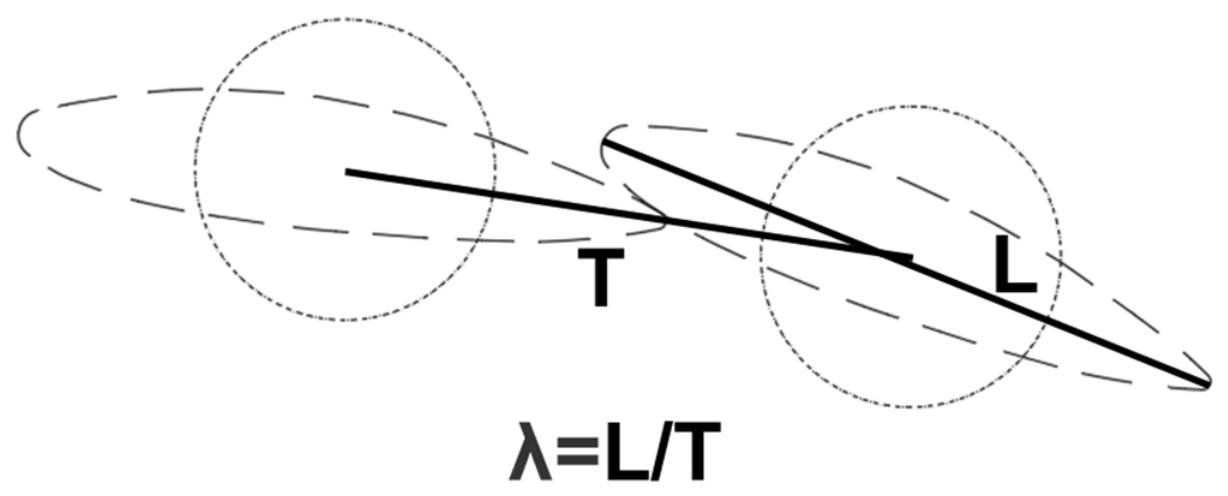
Guide vane overlap describes the circumferential overlap degree between adjacent guide vanes at small openings, as shown in Figure 16, and can be expressed as:
λ = L T
where L is the total guide vane profile length, namely the circumferential contour arc length, and T is the arc length between the centers of adjacent guide vanes.
From the perspective of hydraulic mechanisms, adjusting guide vane overlap essentially changes the local flow-passage geometry and pressure distribution in the guide vane region. Excessive overlap can significantly intensify jet acceleration, flow separation, interaction among leakage flows, and local pressure gradients, thereby increasing the probability of flow instability and abnormal hydraulic excitation.
Field operation and maintenance experience from multiple pumped storage power stations confirm this pattern. At the Y pumped storage power station, for example, the guide vane overlap ratio was reduced from 1.09 to approximately 1.01 during unit guide vane modification, and the abnormal noise disappeared completely after the modification. Similar patterns were also observed at the M, J, C, and H stations.
Engineering statistical results further indicate that a critical threshold exists for guide vane overlap. According to field data from the China Institute of Water Resources and Hydropower Research (IWHR), when the overlap ratio exceeds 1.06, the probability of abnormal noise increases sharply; when the value exceeds 1.07, a high incidence of noise becomes especially evident. Therefore, engineering practice suggests that controlling the guide vane overlap ratio below 1.03 can effectively reduce the risk of guide vane noise faults.
However, reducing guide vane overlap may also adversely affect unit operating efficiency, and clearance-parameter adjustment must therefore balance stability and efficiency [125].

4.4. Avoiding Vibration-Prone Operating Regions

Analysis shows that the occurrence of guide vane abnormal noise is clearly condition-dependent. It is steadily triggered within the guide vane small openings region and can also easily occur during the transition from PO to SCP. This indicates that abnormal noise is directly associated with specific operating regions rather than being a purely random transient phenomenon.
Comparisons of operating characteristics among different units show that key design parameters differ among units from different power stations, including rated power level and runner diameter. Such structural-parameter variations may further influence flow stability under small openings and increase the sensitivity of guide vane abnormal noise. This suggests that structural-parameter differences may alter the unit response to low flow unstable operating conditions.
Based on this understanding, an engineering control approach has gradually formed in which dangerous operating regions are avoided to suppress abnormal noise. Although some power stations have treated abnormal noise using the measures described above and achieved certain effects, some stations still explicitly restrict operation during the PO-SCP condition. By actively avoiding high-risk regions such as small openings and operating condition transition, the operating path reduces the probability of abnormal noise and vibration and thereby realizes avoidance and control of instability problems.

4.5. Summary of Control Strategies

This review summarizes data from power stations where near-zero flow instability has occurred and compiles the corresponding phenomena, possible causes, and mitigation measures, as shown in Table 3. The information presented in Table 3 is sourced from two types of channels: some are extracted from the publicly available literature, and others are compiled from academic lectures, technical presentations, and conference communications.

5. Conclusions and Outlooks

5.1. Conclusions

This review identifies near-zero flow instability in pump mode as a distinct problem in pump turbines. It frequently occurs during SCP–PO and has been reported in several pumped storage power stations. Its main risks are hydraulic instability, guide vane vibration, abnormal noise, and reduced operational safety in high-head units. The main conclusions are as follows.
(1)
The hydraulic instability is governed by coupled flow mechanisms.
Clearance leakage flow, bi-stable flow, and RSI are the main flow phenomena identified under near-zero flow conditions. Their interaction produces strong pressure fluctuations, local flow separation, leakage vortices, and unsteady hydraulic loads. Current experimental and numerical methods can capture these structures, but the dominant flow mechanism remains case-dependent.
(2)
The structural response is mainly controlled by FSI.
Field evidence shows that hydraulic instability can trigger severe vibration and abnormal noise, with noise levels exceeding 140 dB in some stations. Existing studies indicate two possible mechanisms: forced vibration caused by hydraulic excitation approaching a structural natural frequency, and self-excited vibration sustained by an FSI feedback loop. The latter better explains the randomness, non-repeatability, and persistence of guide vane vibration observed in several engineering cases.
(3)
Mitigation must match the dominant instability mechanism.
Four strategies have been used in practice: MGV, start-up and shutdown sequence optimization, structural modification, and avoidance of dangerous operating regions. These measures can suppress instability, but their effectiveness depends on the flow pattern, guide vane clearance, overlap ratio, structural stiffness, damping, and unit-specific operating sequence.
Several issues remain unresolved. The dominant hydraulic source of near-zero flow instability has not been directly confirmed by experiments. The relative roles of forced vibration and self-excited vibration are still unclear in many power stations. Low-cost and easily implementable control methods remain limited. In addition, no universal design parameter has been established to eliminate abnormal noise at the design stage. Guide vane overlap may be a promising parameter, but further evidence is still needed.

5.2. Outlooks

Considering the unresolved controversies, future research should focus on the following directions.
(1)
Mechanism identification.
Future studies should identify the dominant sources of hydraulic instability and guide vane resonance during frequent start-up and shutdown processes [126]. The key task is to clarify how clearance leakage flow, bi-stable flow, RSI, and FSI interact under near-zero flow conditions in pump mode [98,127].
(2)
Multiscale numerical simulation.
Numerical methods should be extended from single-component flow analysis to multiscale coupled simulation. Future models should capture millimeter-scale clearance flow at extremely small openings, meter-scale three-dimensional flow inside the pump turbine, and kilometer-scale transient coupling in upstream and downstream waterways. Coupled structural simulation and FSI modeling should also be improved to resolve the transmission path from hydraulic excitation to structural response.
(3)
Engineering database and AI-assisted prediction.
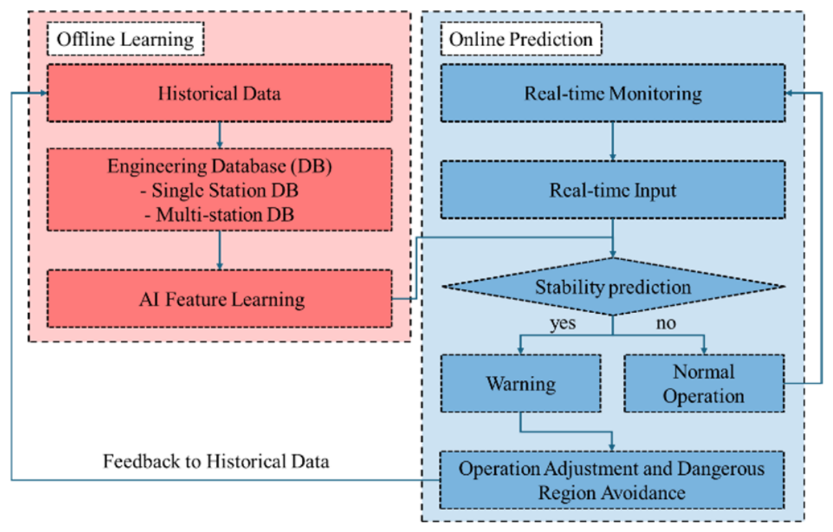
Long-term monitoring data from high-head pumped storage power stations remain insufficient. Future work should build single-station abnormal-noise databases and cross-station historical databases containing flow rate, head, guide vane opening, vibration, pressure fluctuation, and noise data. Based on these datasets, AI-assisted methods can be used for unit feature recognition, stability prediction, and early warning. As shown in Figure 17, the auxiliary prediction system can integrate monitoring data, feature extraction, model prediction, risk-threshold judgment, and warning output into a closed workflow. Reduced-order models and machine-learning methods may further improve the efficiency of instability prediction, especially when combined with long-term field-monitoring data. When operating indicators approach risk thresholds, warnings can be issued to help operators avoid dangerous operating regions [128,129].
In summary, future research on the small openings process of pump turbines should systematically incorporate international experience in instability studies of pump turbines under near-zero flow conditions in pump mode.

Author Contributions

Conceptualization, H.Z., Y.Y. and Z.W.; methodology, Y.Y.; validation, Y.Y. and X.Z.; formal analysis, Y.Y.; data curation, Y.Y.; writing—original draft preparation, Y.Y. and X.Z.; writing—review and editing, H.Z., B.W. and Z.W.; visualization, Y.Y.; supervision, Z.W.; project administration, Z.W.; funding acquisition, H.Z., B.W. and J.W. All authors have read and agreed to the published version of the manuscript.

Funding

Supported by State Grid XinYuan Group Co., Ltd. Science and Technology Project (SGXYKJ-2025-039).

Data Availability Statement

All data cited and analyzed in this review are derived from publicly published literature. The relevant original datasets can be accessed via the corresponding references provided in the manuscript. No new raw data were generated in this study.

Conflicts of Interest

Author Hui Zeng, Bin Wang and Jingyu Wan were employed by the company East China Tianhuangping Pumped Storage Co., Ltd. The remaining authors declare no conflicts of interest. The funders (Hui Zeng, Bin Wang and Jingyu Wan) participated in the design of the study, the collection, analyses and interpretation of literature data, the writing and revision of the manuscript, and the decision to publish the results.

Abbreviations

The following abbreviations are used in this manuscript:
PSHPumped Storage Hydropower
PTPump turbine
SCPPumping Condenser Mode
POPumping Operation
CFDComputational Fluid Dynamics
FEAFinite Element Analysis
PIVParticle Image Velocimetry
LDVLaser Doppler Velocimetry
RSIRotor–Stator Interaction
BPFBlade Passing Frequency
FSIFluid–Structure Interaction
MGVMisaligned Guide Vane
AIArtificial Intelligence

References

  1. Kong, Y.; Kong, Z.; Liu, Z.; Wei, C.; Zhang, J.; An, G. Pumped storage power stations in China: The past, the present, and the future. Renew. Sustain. Energy Rev. 2017, 71, 720–731. [Google Scholar] [CrossRef]
  2. Çetinkaya, Ü.; Yeşil, M.; Bayındır, R.; Irmak, E. Technical analysis and strategic insights from the 2025 Spain blackout. In Proceedings of the 2025 13th International Conference on Smart Grid (icSmartGrid); IEEE: Piscataway, NJ, USA, 2025; pp. 809–815. [Google Scholar]
  3. Pandey, H.W.; Kumar, R.; Mandal, R.K. Ranking of mitigation strategies for duck curve in Indian active distribution network using MCDM. Int. J. Syst. Assur. Eng. Manag. 2023, 14, 1255–1275. [Google Scholar] [CrossRef]
  4. Lu, J.; Wang, C.; Tao, R.; Yao, Z.; Xiao, R.; Liu, W. Transient hydrodynamic instability during the rapid closing process of the guide vanes of pump turbines under power generation conditions. Proc. Inst. Mech. Eng. Part C J. Mech. Eng. Sci. 2026, 09544062261447373. [Google Scholar] [CrossRef]
  5. Yan, Y.; Wang, Z.; Wu, H.; Luo, Y. Propagation mechanism of vibration in mountains with penstocks induced by water hammer waves. In Proceedings of the ASME Fluids Engineering Division Summer Meeting; AMSE: New York, NY, USA, 2025; Volume 89008, p. V002T08A007. [Google Scholar]
  6. Zuo, Z.; Fan, H.; Liu, S.; Wu, Y. S-shaped characteristics on the performance curves of pump-turbines in turbine mode—A review. Renew. Sustain. Energy Rev. 2016, 60, 836–851. [Google Scholar] [CrossRef]
  7. Li, D.; Wang, H.; Qin, Y.; Han, L.; Wei, X.; Qin, D. Entropy production analysis of hysteresis characteristic of a pump-turbine model. Energy Convers. Manag. 2017, 149, 175–191. [Google Scholar] [CrossRef]
  8. Cao, J. Study on Lubrication Characteristics of Thrust Bearings and Shafting Dynamic Characteristics of Pump-Turbine Units. Ph.D. Thesis, Tsinghua University, Beijing, China, 2023. [Google Scholar]
  9. Casartelli, E.; Del Rio, A.; Mangani, L.; Schmid, A. Capturing the S-shape of pump-turbines by computational fluid dynamics simulations using an anisotropic turbulence model. J. Fluids Eng. 2022, 144, 021203. [Google Scholar]
  10. Li, D.; Gong, R.; Wang, H.; Wei, X.; Liu, Z.; Qin, D. Numerical investigation on transient flow of a high-head low-specific-speed pump-turbine in pump mode. J. Renew. Sustain. Energy 2015, 7, 063111. [Google Scholar] [CrossRef]
  11. Huang, H. Internal Flow Field and One-Way Fluid-Structure Interaction Analysis in the Small Guide Vane Opening Region during Francis Turbine Start-Up. Master’s Thesis, Xi’an University of Technology, Xi’an, China, 2021. [Google Scholar]
  12. Mao, X.; Hu, J.; Pan, Z.; Zhong, P.; Zhang, N. A brief review of recent research on reversible Francis pump turbines in pumped storage plants. Energies 2025, 18, 394. [Google Scholar] [CrossRef]
  13. Yang, M.; Shi, J.; Chen, Y.; Sun, X.; Xue, T.; Yao, W.; Zhang, W.; Ge, X.; Zheng, Y.; Ye, C. Flow-control with fins for hump suppression in pumped-storage pump-turbines. Water 2026, 18, 801. [Google Scholar] [CrossRef]
  14. Zhang, T.; Li, D.; Lu, M. A review of pressure fluctuation in pump-turbines for pumped hydro energy storage with ultra-large head variation: Mechanisms, research methods, and control measures. J. Energy Storage 2026, 162, 121996. [Google Scholar] [CrossRef]
  15. He, L.; Zhou, L.; Ahn, S.-H.; Wang, Z.; Nakahara, Y.; Kurosawa, S. Evaluation of gap influence on the dynamic response behavior of pump-turbine runner. Eng. Comput. 2019, 36, 491–508. [Google Scholar] [CrossRef]
  16. Fu, X.; Zuo, Z.; Chang, H.; Li, D.; Wang, H.; Wei, X. Mechanism of low-frequency high-amplitude pressure fluctuation in a pump-turbine during the load rejection process. J. Hydraul. Res. 2020, 59, 280–297. [Google Scholar] [CrossRef]
  17. Kang, W.; Zhou, L.; Wang, Z. Analysis of flow characteristics and cavitation in the vanes of a reversible pump-turbine in pump mode. J. Energy Storage 2023, 68, 107690. [Google Scholar] [CrossRef]
  18. Liang, A.; Chang, Y.; Zhang, W.; Yao, Z.; Zhu, B.; Wang, F. Research on the evolution law and energy loss characteristics of rotating stall in a pump-turbine under pump mode. Energy 2025, 330, 136696. [Google Scholar] [CrossRef]
  19. Yang, J.; Cheng, X.; Liu, X.; Feng, X.; Pan, K. Influence mechanism of impeller internal flow structure in the pump-mode hump instability of pump turbine: A compressible flow solution. J. Energy Storage 2024, 101, 112049. [Google Scholar] [CrossRef]
  20. Lu, J.; Guo, Y.; Zhou, B.; Zhao, M.; Zhang, C.; Huang, C.; Liu, X. Transient hydraulic characteristics and energy loss mechanisms in a variable-speed pumped storage unit operating in pump mode. J. Energy Storage 2026, 151, 120313. [Google Scholar] [CrossRef]
  21. Song, X.; Liu, C. Experimental investigation of floor-attached vortex effects on the pressure pulsation at the bottom of the axial flow pump sump. Renew. Energy 2020, 145, 2327–2336. [Google Scholar] [CrossRef]
  22. Müller, A.; Favrel, A.; Landry, C.; Avellan, F. Fluid-structure interaction mechanisms leading to dangerous power swings in Francis turbines at full load. J. Fluids Struct. 2017, 69, 56–71. [Google Scholar] [CrossRef]
  23. Tao, R.; Xiao, R.; Wang, F.; Liu, W. Cavitation behavior study in the pump mode of a reversible pump-turbine. Renew. Energy 2018, 125, 655–667. [Google Scholar] [CrossRef]
  24. Nennemann, B.; Parkinson, E. YiXing pump turbine guide vane vibrations: Problem resolution with advanced CFD analysis. IOP Conf. Ser. Earth Environ. Sci. 2010, 12, 012057. [Google Scholar] [CrossRef]
  25. Li, Q.; Yu, J.; Ren, S.; Chen, L.; Jiang, M.; Huang, Z.; Lu, J.; Xiong, T.; Zhou, W. Self-excited vibration of the guide vane mechanism of the Jiangsu Yixing Pumped Storage Power Station pump-turbine. In Proceedings of the 18th Academic Symposium on Chinese Hydropower Equipment; China Machine Press: Beijing, China, 2011; pp. 108–112. [Google Scholar]
  26. Nennemann, B.; Sallaberger, M.; Henggeler, U.; Gentner, C.; Parkinson, E. Assessment of guide vane self-excitation stability at small openings in pump flow. IOP Conf. Ser. Earth Environ. Sci. 2012, 15, 062032. [Google Scholar] [CrossRef]
  27. He, L.Y.; Wang, Z.W.; Kurosawa, S.; Nakahara, Y. Resonance investigation of pump-turbine during start-up process. IOP Conf. Ser. Earth Environ. Sci. 2014, 22, 032024. [Google Scholar] [CrossRef]
  28. Zuo, Z.; Liu, S.; Sun, Y.; Wu, Y. Pressure fluctuations in the vaneless space of high-head pump-turbines—A review. Renew. Sustain. Energy Rev. 2015, 41, 965–974. [Google Scholar] [CrossRef]
  29. Zhang, Y.; Zhang, Y.; Wu, Y. A review of rotating stall in reversible pump turbine. Proc. Inst. Mech. Eng. Part C J. Mech. Eng. Sci. 2017, 231, 1181–1204. [Google Scholar]
  30. Li, Z.; Bi, H.; Karney, B.; Wang, Z.; Yao, Z. Three-dimensional transient simulation of a prototype pump-turbine during normal turbine shutdown. J. Hydraul. Res. 2017, 55, 520–537. [Google Scholar] [CrossRef]
  31. Tao, R.; Zhou, X.; Xu, B.; Wang, Z. Numerical investigation of the flow regime and cavitation in the vanes of reversible pump-turbine during pump mode’s starting up. Renew. Energy 2019, 141, 9–19. [Google Scholar] [CrossRef]
  32. Yang, M.; Chen, H.; Zhu, D.; Meng, F.; Zhou, Y. Analysis and Research on Back-to-Back Startup Failure of Pumped Storage Power Station Unit. Sci. Technol. Inf. 2021, 19, 29–31. [Google Scholar] [CrossRef]
  33. Yang, H.; Li, Q.; Gao, X.; Zhang, H.; Zhao, X. Analysis and treatment of abnormal noise during pump mode start-up of a pumped storage power station. Mech. Electr. Technol. Hydropower Stn. 2023, 46, 21–22+93. [Google Scholar]
  34. Chen, H.; Liu, H.; Wang, Y.; Zhou, D.; Xu, H.; Kan, K. Pressure pulsation during low-head start-up transient in a pumped-storage hydropower unit. Trans. Chin. Soc. Agric. Eng. 2023, 39, 63–72. [Google Scholar]
  35. Huang, W.; Bi, H.; Ye, Y.; Zhang, S.; Yin, X.; Huang, X.; Wang, Z.; Jin, Z. Study on hydraulic performance of pump-turbine in start-up process. J. Hydroelectr. Eng. 2023, 42, 97–104. [Google Scholar]
  36. Wang, T.; Yu, C.; Yang, H.; Zhao, Y.; Zhou, Y.; Liu, H.; Zhou, D.; Kan, K. Investigations into hydraulic instability during the start-up process of a pump-turbine under low-head conditions. Processes 2024, 12, 1876. [Google Scholar] [CrossRef]
  37. Xia, M.; Zhao, W.; Wang, Z.; Qiao, M. Pulsation stability analysis of a prototype pump-turbine during pump mode start-up: Field test observations and insights. Processes 2024, 12, 838. [Google Scholar] [CrossRef]
  38. Xia, M.; Wang, Z.; Wang, W.; Yang, J.; Zhao, W.; Qiao, M. Hidden hydraulic instability: Clearance flow dynamics during pump-turbine pump mode start-up. Renew. Energy 2025, 252, 123312. [Google Scholar] [CrossRef]
  39. Yuan, X.; Zhao, K.; Xu, Y. Start-up process of pumped storage unit for avoiding S-shaped region based on geometric perspective method. Water 2025, 17, 1999. [Google Scholar] [CrossRef]
  40. Xin, L.; Li, Q.; Chen, X. Study on clearance flow distortion and associated force response in pump-turbines operating under S-characteristic conditions. J. Energy Storage 2026, 153, 121027. [Google Scholar] [CrossRef]
  41. Yan, X.; Zhang, F.; Kan, K.; Zheng, Y.; Xu, Z.; Chen, H.; Binama, M. Hydraulic instability of pump-turbine during fast pump-to-turbine transition under different control schemes: Changing guide vane pre-opening angles. Energy Convers. Manag. 2025, 323, 119274. [Google Scholar] [CrossRef]
  42. Alloin, E.; Balarac, G.; Métais, O.; Laurant, Y.; Ségoufin, C. Large Eddy Simulations of the part-load instability in a pump-turbine in pump mode. J. Fluids Eng. 2026, 148, 041204. [Google Scholar]
  43. Yao, L.; Luo, X.; Wang, L.; Feng, J.; Zhu, G.; Li, C. Mechanistic insights into the unstable flow of pump-turbine unit at varied heads during pump mode start-up. J. Energy Storage 2026, 149, 120021. [Google Scholar] [CrossRef]
  44. Zhang, P.; Cheng, Y.; Hu, Z.; Xue, S.; Li, W.; Zhao, Z.; Yang, W.; Hu, Z. CFD-based hydraulic-mechanical-electrical coupled simulation method for variable-speed pumped storage units. Energy 2025, 329, 136701. [Google Scholar]
  45. China Renewable Energy Engineering Institute (CREEI). Available online: http://www.creei.cn/web/index.html (accessed on 3 July 2026).
  46. Wu, H.; Yan, Y.; Wang, Z.; Shi, Y. Pressure fluctuation analysis of a pumped storage system with three-dimensional penstock during ball valve closure: Turbine mode. In Proceedings of the ASME Fluids Engineering Division Summer Meeting; AMSE: New York, NY, USA, 2025; Volume 88995, p. V001T06A004. [Google Scholar]
  47. Xu, L.; Kan, K.; Zheng, Y.; Liu, D.; Binama, M.; Xu, Z.; Yan, X.; Guo, M.; Chen, H. Rotating stall mechanism of pump-turbine in hump region: An insight into vortex evolution. Energy 2024, 292, 130579. [Google Scholar] [CrossRef]
  48. Zuo, Z.; Liu, S. Flow-induced instabilities in pump-turbines in China. Engineering 2017, 3, 504–511. [Google Scholar] [CrossRef]
  49. Liang, A.; Li, H.; Zhang, W.; Yao, Z.; Zhu, B.; Wang, F. Study on pressure fluctuation and rotating stall characteristics in the vaneless space of a pump-turbine in pump mode. J. Energy Storage 2024, 94, 112385. [Google Scholar] [CrossRef]
  50. Eisele, K.; Muggli, F.; Zhang, Z.; Casey, M.; Sallaberger, M.; Sebestyen, A. Experimental and numerical studies of flow instabilities in pump-turbine stages. In Proceedings of the XIX IAHR Symposium on Hydraulic Machinery and Systems; World Scientific Publishing Co.: Singapore, 1998; pp. 168–175. [Google Scholar]
  51. Xue, P.; Liu, Z.; Lu, L.; Gao, Z.; Meng, X. Experimental research on the rotating stall of a pump turbine in pump mode. Water 2019, 11, 2426. [Google Scholar] [CrossRef]
  52. Acharya, N.; Gautam, S.; Chitrakar, S.; Trivedi, C.; Dahlhaug, O.G. Leakage vortex progression through a guide vane’s clearance gap and the resulting pressure fluctuation in a Francis turbine. Energies 2021, 14, 4244. [Google Scholar] [CrossRef]
  53. Song, H.; Zhang, J.; Huang, P.; Cai, H.; Cao, P.; Hu, B. Analysis of rotor-stator interaction of a pump-turbine with splitter blades in a pump mode. Mathematics 2020, 8, 1465. [Google Scholar] [CrossRef]
  54. Lu, J.; Tao, R.; Yao, Z.; Xiao, R.; Liu, W. Transient simulation energy study of fast opening of guide vane during start-up of pump turbine in energy storage mode. Energy 2025, 324, 135964. [Google Scholar] [CrossRef]
  55. Yan, Y.; Lin, X.; Wu, H.; Zhao, X.; Zhang, Z.; Wang, Z. Dynamic response of fluid-solid coupled penstock-mountain system under geostress effects. J. Phys. Conf. Ser. 2025, 3150, 012129. [Google Scholar] [CrossRef]
  56. Chen, L.; Li, J.; Deng, L.; Xie, E.; Yan, X.; Hao, G.; Chen, H.; Xue, H.; Zhong, Z.; Kan, K. Hydraulic instability characteristics of pumped-storage units during the transition from hot standby to power generation. Water 2025, 18, 61. [Google Scholar] [CrossRef]
  57. Tao, R.; Wang, Z. Analysis of the guide vane jet-vortex flow and the induced noise in a prototype pump-turbine. Appl. Sci. 2019, 9, 1971. [Google Scholar] [CrossRef]
  58. Liu, D.; Xu, W.; Zhao, Y. Experimental study of the flow field of a high-head model pump turbine based on PIV technique. J. Hydrodyn. 2021, 33, 1045–1055. [Google Scholar] [CrossRef]
  59. Deng, Y.; Xu, J.; Li, Y.; Zhang, Y.; Kuang, C. Experimental and Computational Fluid Dynamics Study of the Flow Field of a Model Pump Turbine. Front. Energy Res. 2022, 10, 911874. [Google Scholar] [CrossRef]
  60. Deng, W.; Xu, L.; Li, Z.; Tang, W.; Wang, X.; Shang, L.; Liu, D.; Liu, X. Stability Analysis of Vaneless Space in High-Head Pump-Turbine under Turbine Mode: Computational Fluid Dynamics Simulation and Particle Imaging Velocimetry Measurement. Machines 2022, 10, 143. [Google Scholar] [CrossRef]
  61. Xu, L.; Jin, X.; Li, Z.; Deng, W.; Liu, D.; Liu, X. Particle Image Velocimetry Test for the Inter-Blade Vortex in a Francis Turbine. Processes 2021, 9, 1968. [Google Scholar] [CrossRef]
  62. Liu, D.; Zhao, Y.; Zuo, Z. Experimental research on flow field in the draft tube of pump turbines based on LDV. In Proceedings of the 29th IAHR Symposium on Hydraulic Machinery and Systems, Kyoto, Japan, 17–21 September 2019. [Google Scholar]
  63. Deng, W.; Li, Z.; Ji, L.; Shang, L.; Liu, D.; Liu, X. Laser Doppler Velocimetry Test of Flow Characteristics in Draft Tube of Model Pump Turbine. Processes 2022, 10, 1323. [Google Scholar] [CrossRef]
  64. Ji, L.; Xu, L.; Peng, Y.; Zhao, X.; Li, Z.; Tang, W.; Liu, D.; Liu, X. Experimental and Numerical Simulation Study on the Flow Characteristics of the Draft Tube in Francis Turbine. Machines 2022, 10, 230. [Google Scholar] [CrossRef]
  65. Zhang, Y.H.; Wang, J.L.; Su, W.T.; Zhao, Y.; Chen, Y.L.; Chen, T.P.; Wu, J. Rotating stall characteristics in the hump region of a pump turbine: Application of modal decomposition. J. Appl. Fluid Mech. 2025, 18, 2968–2987. [Google Scholar] [CrossRef]
  66. Sun, L.; Wen, M.; Sun, S.; Xu, Z.; Guo, P. Numerical investigation of erosion response towards a high-head Francis turbine with special emphasis on clearance sizes effect of guide vane. Eng. Appl. Comput. Fluid Mech. 2025, 19, 2565802. [Google Scholar] [CrossRef]
  67. Yan, J.; Zuo, Z.; Guo, W.; Hou, H.; Zhou, X.; Chen, H. Influences of wear-ring clearance leakage on performance of a small-scale pump-turbine. Proc. Inst. Mech. Eng. Part A J. Power Energy 2020, 234, 454–469. [Google Scholar]
  68. Gautam, S.; Neopane, H.P.; Acharya, N.; Chitrakar, S.; Thapa, B.S.; Zhu, B. Sediment erosion in low-specific-speed Francis turbines: A case study on effects and causes. Wear 2020, 442, 203152. [Google Scholar] [CrossRef]
  69. Song, X.; Luo, Y.; Wang, Z. Mechanism of the influence of sand on the energy dissipation inside the hydraulic turbine under sediment erosion condition. Energy 2024, 294, 130794. [Google Scholar] [CrossRef]
  70. Ji, L.; Liu, Z.; Li, W.; Shi, W.; Tian, F.; Pu, W.; Yang, Y.; Xiao, C.; Agarwal, R. PIV investigation of stalled flow field near the blade rim region of mixed-flow pump under different tip clearances. Flow Meas. Instrum. 2024, 99, 102668. [Google Scholar] [CrossRef]
  71. Lin, J.; Pei, J.; Wang, W.; Chen, J.; Gan, X.; Cantrak, D. Unsteady fluid-structure interaction characteristics of a reversible mixed-flow pump in micro-pumped hydro storage. Phys. Fluids 2025, 37, 064106. [Google Scholar] [CrossRef]
  72. Zhang, F.; Ni, J.; Liu, R.; Wei, H. Unit stability analysis for Jixi Pumped Storage Power Station. J. Hydroelectr. Eng. 2021, 40, 112–123. [Google Scholar]
  73. Ma, W.; Liang, W.; Nan, H.; Zhao, D.; Li, J.; Dong, Y. Influence of runner seal clearance on unit stability in Francis turbines. J. Hydroelectr. Eng. 2010, 29, 219–223. [Google Scholar]
  74. Matsumoto, Y.; Beylich, A.E. Influence of homogeneous condensation inside a small gas bubble on its pressure response. J. Fluids Eng. 1985, 107, 281–286. [Google Scholar] [CrossRef]
  75. Hu, Y.; Zhu, K.; Xi, B. Numerical study of cavitation erosion on a rigid wall. Chin. J. Appl. Mech. 2004, 21, 22–25. [Google Scholar]
  76. Chen, Y.; Zhang, J.; Zhang, L.; Zhu, Z.; Li, C. Sediment Erosion Characteristics and Mechanism on Guide Vane End-Clearance of Hydro Turbine. Appl. Sci. 2019, 9, 4137. [Google Scholar] [CrossRef]
  77. Pulpitel, L. Self-excited vibration of pump turbine guide vanes. In Proceedings of the IAHR 11th Symposium on Hydraulic Machinery, Equipment and Cavitation, Amsterdam, The Netherlands, 9–11 September 1982. [Google Scholar]
  78. Pulpitel, L. Dynamic Problems of Pump Turbines. In Proceedings of the 14th IAHR Symposium on Hydraulic Machinery, Equipment and Cavitation, Ljubljana, Yugoslavia, 13–15 September 1988. [Google Scholar]
  79. Kang, W.; Liang, Q.; Zhou, L.; Wang, Z. Numerical investigation on torsional mode self-excited vibration of guide vane in a reversible pump-turbine during pump mode’s starting up. J. Appl. Fluid Mech. 2022, 15, 1789–1799. [Google Scholar]
  80. Liu, D.; Shi, Q.; Zhao, Y.; Wen, G. Numerical Simulation of Cavitation Characteristics of a Pump-Turbine and Comparison with Model Test Results. Int. J. Hydropower Dams 2012, 19, 78. [Google Scholar] [CrossRef]
  81. Wang, Z. Fundamentals of Fluid Machinery; Tsinghua University Press: Beijing, China, 2006. [Google Scholar]
  82. Zhang, D.; Xiao, Y.; Huang, X.; Quan, Q.; Jia, Z.; Wang, Z. Dynamic characteristic analysis of a pump-turbine unit under the high pressure pulsation operating condition-fluid dynamics analysis. In Proceedings of the 2022 12th International Conference on Power and Energy Systems (ICPES), Guangzhou, China, 23–25 December 2022; pp. 336–341. [Google Scholar]
  83. Chen, L.; Liu, Y.; Xu, L. Correlation between pressure fluctuations of pump-turbines and vibration responses of units and powerhouse. Hydropower Pumped Storage 2025, 11, 1–9. [Google Scholar]
  84. Wang, W.; Yuan, S.; Pei, J.; Zhang, J.; Yuan, J. Numerical analysis of the clocking effect on the pressure fluctuation in the centrifugal pump with vaned diffuser. J. Mech. Eng. 2015, 51, 185–192. [Google Scholar] [CrossRef]
  85. Liu, Y.; Yang, J.; Fang, M.; Li, X.; Wu, Y.; Lu, Y. Computational research on the formation mechanism of rotating stall induced by rotor-stator interaction in a pump-turbine under pump mode. Water 2025, 17, 2538. [Google Scholar] [CrossRef]
  86. Jin, G.; Li, Q.; Dong, Z.; Wang, Y. Stress Calculation and Analysis of Movable Guide Vanes at Henan Tianchi Pumped Storage Power Station. In Research and Practice of Hydropower Equipment—Proceedings of the 23rd Academic Symposium on Chinese Hydropower Equipment; China Water & Power Press: Beijing, China, 2023; pp. 133–137. [Google Scholar]
  87. Liu, J.T.; Liu, S.H.; Sun, Y.K.; Wu, Y.L.; Wang, L.Q. Prediction of Pressure Fluctuation of a Pump-Turbine at No-Load Opening. J. Eng. Therm. Energy Power 2012, 33, 411–414. [Google Scholar]
  88. Tanaka, H. Vibration Behavior and Dynamic Stress of Runners of Very High Head Reversible Pump Turbines. In Proceedings of the 15th IAHR Symposium on Hydraulic Machinery and Systems, Belgrade, Yugoslavia, 11–14 September 1990. [Google Scholar]
  89. Coutu, A.; Proulx, D.; Coulson, S.; Demers, A. Dynamic Assessment of Hydraulic Turbines. In Proceedings of the Hydro Vision 2004, Montreal, QC, Canada, 16–20 August 2004. [Google Scholar]
  90. Kong, L. Analysis of instantaneous abnormal noise during operating-condition transition of high-head pump-turbines. Mech. Electr. Technol. Hydropower Stn. 2004, 6, 12–14+60. [Google Scholar]
  91. Wang, H.; Pang, J.; Lai, Z.; Gan, L.; Huang, D.; Hua, H.; Yu, Z.; Liu, X. Internal flow stability of a Francis turbine under wide load operating range. Phys. Fluids 2025, 37, 023346. [Google Scholar] [CrossRef]
  92. Zhang, X.; Pavesi, G.; Xu, Z.; Song, X.; Tang, F. Phase classification and transient effects of the start-up process of multi-functional pump station in pump mode. J. Energy Storage 2024, 100, 113517. [Google Scholar] [CrossRef]
  93. Wang, L.; Feng, J.; Luo, X.; Zhu, G.; Lu, J.; Liu, Y. Numerical investigation of energy dissipation and vortex characteristics on the S-shaped region of a reversible pump-turbine. J. Energy Storage 2024, 99, 113447. [Google Scholar] [CrossRef]
  94. Liu, B.; Feng, J.; Zhu, G.; Ge, Z.; Gao, L.; Luo, X. Chaotic characteristics of pressure fluctuations and operation state recognition in S-shaped region of a pump turbine. Mech. Syst. Signal Process. 2025, 239, 113294. [Google Scholar] [CrossRef]
  95. Patil, S.S.; Verma, H.K.; Kumar, A. Efficiency measurement of hydro machine by thermodynamic method. In Proceedings of the 8th International Conference on Hydraulic Efficiency Measurements (IGHEM 2010), Roorkee, India, 21–23 October 2010. [Google Scholar]
  96. Roth, S.; Hasmatuchi, V.; Botero, F.; Farhat, M.; Avellan, F. Fluid-structure coupling in the guide vanes cascade of a pump-turbine scale model. IOP Conf. Ser. Earth Environ. Sci. 2010, 12, 012074. [Google Scholar] [CrossRef]
  97. Yang, C.; Zhang, Y.; Zheng, X.; Li, J. Transient pressure pulsation analysis and condition assessment for pumped storage hydropower unit during start-up process based on adaptive chirp mode decomposition. J. Energy Storage 2026, 165, 122292. [Google Scholar] [CrossRef]
  98. Hu, C.; Zhang, X.; Shen, W.; Liu, H.; Tang, F.; Yan, B. Study on pressure field characteristics of high-specific-speed axial-flow pump under full working conditions based on wavelet transform. Phys. Fluids 2025, 37, 025207. [Google Scholar] [CrossRef]
  99. Zhang, D.; Quan, Q.; Huang, X.; Wang, Z.; Wang, B.; Xiao, Y. Transient flow-induced stress investigation on a prototype reversible pump-turbine runner. Energies 2024, 17, 3026. [Google Scholar] [CrossRef]
  100. Østby, P.T.; Myrvold, E.; Billdal, J.T.; Haugen, B. Excitation of torsional modes in guide vanes. IOP Conf. Ser. Earth Environ. Sci. 2019, 240, 062010. [Google Scholar] [CrossRef]
  101. Nicolet, C.; Ruchonnet, N.; Alligné, S.; Koutnik, J.; Avellan, F. Hydroacoustic simulation of rotor-stator interaction in resonance conditions in Francis pump-turbine. IOP Conf. Ser. Earth Environ. Sci. 2010, 12, 012005. [Google Scholar] [CrossRef]
  102. Yang, H.; He, Q.; Huang, X.; Yang, M.; Bi, H.; Wang, Z. Experimental and numerical investigation of rotor-stator interaction in a large prototype pump-turbine in turbine mode. Energies 2022, 15, 5523. [Google Scholar] [CrossRef]
  103. Zhang, F.; Lowys, P.Y.; Houdeline, J.B.; Guo, X.; Hong, P.; Laurant, Y. Pump-turbine rotor-stator interaction induced vibration: Problem resolution and experience. IOP Conf. Ser. Earth Environ. Sci. 2021, 774, 012124. [Google Scholar] [CrossRef]
  104. Yan, J.P.; Seidel, U.; Koutnik, J. Numerical Simulation of Hydrodynamics in a Pump-Turbine at Off-Design Operating Conditions in Turbine Mode. IOP Conf. Ser. Earth Environ. Sci. 2012, 15, 032041. [Google Scholar] [CrossRef]
  105. Presas, A.; Valentin, D.; Egusquiza, E.; Valero, C.; Seidel, U. On the excitation of a submerged disk-like structure with RSI patterns. In Proceedings of the Cavitation and Dynamic Problems; University of Ljubljana: Ljubljana, Slovenia, 2015; p. 259. [Google Scholar]
  106. Valero, C.; Egusquiza, M.; Egusquiza, E.; Presas, A.; Valentin, D.; Bossio, M. Extension of operating range in pump-turbines: Influence of head and load. Energies 2017, 10, 2178. [Google Scholar] [CrossRef]
  107. Das, A.; Pal, S.; Ziyi, S.; Rout, M.; Inaba, K.; Karmakar, A. Natural frequency and resonance study of FGM turbo-machinery blade using Campbell diagram. In Proceedings of the ASME Gas Turbine India Conference; AMSE: New York, NY, USA, 2021; Volume 85536, p. V001T10A009. [Google Scholar]
  108. Liang, Q.; Kang, W.; Zhou, L.; Wang, Z. Influence of end wall clearance on guide vane self-excited vibrations at small openings during pump mode’s starting up process of a reversible pump turbine. J. Mar. Sci. Eng. 2022, 10, 528. [Google Scholar] [CrossRef]
  109. Roth, S. Fluid-Structure Coupling Effects on the Dynamic Response of Pump-Turbine Guide Vanes. Ph.D. Thesis, École Polytechnique Fédérale de Lausanne, Lausanne, Switzerland, 2012. [Google Scholar]
  110. Liang, Q.; Kang, W.; Zhou, L.; Wang, Z. Numerical investigation of the flow regime in the vanes and the torsional self-excited vibration of guide vane in the pump mode of a reversible pump-turbine. Processes 2022, 10, 2314. [Google Scholar] [CrossRef]
  111. Kang, W. Unstable Flow Characteristics and Control Methods for a Reversible Pump Turbine under Small Guide Vane Opening Conditions in Pump Mode. Ph.D. Thesis, China Agricultural University, Beijing, China, 2023. [Google Scholar]
  112. Zhang, Y.H.; Zhang, Y.W.; Liu, G.R.; Teng, Y.; Guan, X.B.; Fan, H.G.; Chen, F.N.; Liu, D.Y.; Cao, Y.; Zhou, L. Unsteady characteristics of hydraulic torque of guide vanes of a pump turbine. Mech. Eng. Technol. 2018, 7, 409–417. [Google Scholar]
  113. Cao, J.; Luo, Y.; Zhuang, J.; Li, X.; Wang, Z. Effect of the pressure balance device on the flow characteristics of a pump-turbine. Proc. Inst. Mech. Eng. Part A J. Power Energy 2022, 236, 1533–1543. [Google Scholar] [CrossRef]
  114. Li, H.; Zhou, J.; Zhang, Y. Self-excited vibration of pumped storage power station’s main inlet valve based on EWT and modified Morris method. J. Vib. Shock 2019, 38, 52–57. [Google Scholar]
  115. Li, Q.; Zhang, Z.; Li, R.; Song, Q.; Zhang, J. Pressure pulsation characteristics in the vaneless space of a pump-turbine with an MGV device. J. Drain. Irrig. Mach. Eng. 2018, 36, 1270–1275. [Google Scholar]
  116. Lu, J.; Han, X.; Tao, R.; Xiao, R.; Liang, Q. Research on transient performance changes during the non-simultaneous opening process of guide vanes in reversible pump-turbine units in pump mode. Energy 2025, 335, 138331. [Google Scholar] [CrossRef]
  117. Shi, G.; Hao, Z.; Peng, X.; Wen, H.; Lv, W.; Fu, J. Analysis of vortex characteristics in the S-shaped region of a reversible pump-turbine with different guide vane openings based on Omega vortex identification method. J. Energy Storage 2024, 84, 110921. [Google Scholar] [CrossRef]
  118. Liu, Y.; Yu, X.; Zhang, J.; Chen, S.; Zhang, Y. Optimized operation framework of pumped storage power stations with fixed- and variable-speed units sharing a diversion tunnel: Efficiency optimization and transient characteristics analysis. Energy 2025, 336, 138555. [Google Scholar] [CrossRef]
  119. Jin, F.; Luo, Y.; Wang, Z. Research on the starting-up process of a prototype reversible pump turbine with misaligned guide vanes: An energy loss analysis. Energy 2024, 304, 132219. [Google Scholar] [CrossRef]
  120. Xu, Y.; Zhang, W.; Wang, Z.; Zhang, J.; Ahn, S.H.; Zhou, C.; Luo, Y. Numerical analysis of the effect of misaligned guide vanes on improving S-shaped characteristics for a pump-turbine. J. Fluids Eng. 2018, 140, 031102. [Google Scholar]
  121. Lu, Z.; Xiao, R.; Tao, R.; Li, P.; Liu, W. Influence of guide vane profile on the flow energy dissipation in a reversible pump-turbine at pump mode. J. Energy Storage 2022, 49, 104161. [Google Scholar] [CrossRef]
  122. Wang, W.; Qiu, G.; Pei, J.; Pavesi, G.; Tai, G.; Yuan, S. Effect of return channel on performance and pressure fluctuation of pump turbine. Phys. Fluids 2024, 36, 105135. [Google Scholar] [CrossRef]
  123. Xue, S.; Cheng, Y.; Li, W.; Guan, Z.; Zhang, J. Enhancing operational stability of an ultra-high-head pump-turbine using guide vanes with horizontal blades. Energy 2025, 139360. [Google Scholar] [CrossRef]
  124. Yang, J.; Feng, X.; Liu, X.; Peng, T.; Chen, Z.; Wang, Z. The suppression of hump instability inside a pump turbine in pump mode using water injection control. Processes 2023, 11, 1647. [Google Scholar] [CrossRef]
  125. Zhou, X.; Zhang, Y.; Cheng, L.; Huang, Q.; Cervantes, M.J. Improvement of S-shaped instability and power performance of a reversible pump-turbine runner. Renew. Energy 2026, 258, 124929. [Google Scholar] [CrossRef]
  126. Fu, X.; Chen, Y.; Li, D.; Zheng, Z.; Wang, H. Comparative research on the performance of three impeller seal clearance structures of pumped-storage units based on improved entropy production theory. Energy 2026, 351, 140818. [Google Scholar] [CrossRef]
  127. Xue, Y.; Jiao, Y.; Cheng, C.; Wang, S.; Yang, B.; Li, H.; Li, W. Numerical and experimental study of structural vibrations in pump turbines. Energy Rep. 2025, 14, 1981–1992. [Google Scholar] [CrossRef]
  128. Tubeuf, C.; aus der Schmitten, J.; Hofmann, R.; Heitzinger, C.; Birkelbach, F. Improving control of energy systems with reinforcement learning: Application to a reversible pump turbine. In Proceedings of the ASME Energy Sustainability Conference; AMSE: New York, NY, USA, 2024; Volume 87899, p. V001T01A001. [Google Scholar]
  129. Tubeuf, C.; Bernhardt, T.; Birkelbach, F.; Hofmann, R.; Maly, A. Reinforcement learning-based real-time control of a reversible pump turbine for reduced response time in pumped hydropower. Energy AI 2026, 24, 100755. [Google Scholar] [CrossRef]
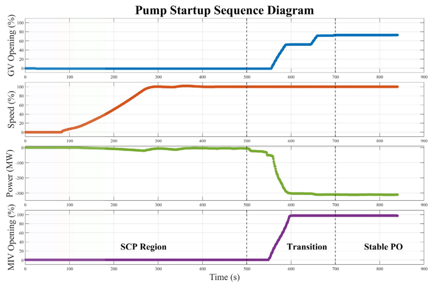
Figure 1. Typical sequence control diagram of SCP-to-PO transition process. Provided by authors.
Machines 14 00820 g001
Figure 5. Guide vane end-face and copper strip wear. Provided by authors.
Machines 14 00820 g005
Figure 7. Schematic diagram of bi-stable flow. Provided by authors.
Machines 14 00820 g007
Figure 9. Vibration acceleration of sensors during guide vane lever arm resonance: (a) vibration acceleration over the complete start-up–shutdown process; (b) enlarged view of the red-boxed region in panel (a), highlighting the vibration during the abnormal-noise event. Provided by authors.
Machines 14 00820 g009
Figure 10. Audio frequency analysis during resonance. Provided by authors.
Machines 14 00820 g010
Figure 11. Acceleration sensors and their arrangement. Provided by authors.
Machines 14 00820 g011
Figure 12. Sound pressure sensors and their arrangement. Provided by authors.
Machines 14 00820 g012
Figure 13. Natural frequencies obtained from modal calculation of the guide vane. Provided by authors.
Machines 14 00820 g013
Figure 14. Schematic diagram of torsional self-excited vibration [79,111].
Machines 14 00820 g014
Figure 15. A typical MGV structure. Provided by authors.
Machines 14 00820 g015
Figure 16. Schematic diagram of guide vane overlap ratio. Provided by authors.
Machines 14 00820 g016
Figure 17. Flowchart of auxiliary prediction system. Provided by authors.
Machines 14 00820 g017
Table 2. Pumped storage power stations where near-zero flow instability has occurred.
Power StationCapacity of a Single Unit and Number of UnitsHeadAverage Annual Pumping Capacity
J300 MW × 6599 m4.020 billion kW·h
T300 MW × 4510 m1.283 billion kW·h
Y250 MW × 4353 m1.959 billion kW·h
M300 MW × 4400 m2.336 billion kW·h
C350 MW × 6756 m3.247 billion kW·h
H300 MW × 6526 m4.104 billion kW·h
X350 MW × 4545 m1.867 billion kW·h
L300 MW × 4640 m2.407 billion kW·h
Table 3. Comparison of instability problems in different pumped storage power stations.
Power StationPhenomenaPossible CausesMitigation Measures
JStart-up/shutdown abnormal noise with intensified top-cover vibration and vaneless space/top-cover pressure fluctuations [75].Zero-flow hydraulic excitation, unstable runner-region water ring, end-wall clearance flow, and spherical valve-induced vaneless space pulsation.Homogenize end-wall clearance; optimize spherical valve-guide vane coordination; apply 3–5% guide vane pre-opening at ~60% spherical valve opening; adjust exhaust-valve timing; prohibit PO-SCP operation.
TSevere guide vane abnormal noise and vibration causing shear-pin damage and component ejection [89].Transition-induced hydraulic excitation and stress concentration at the upper journal–blade junction.Conduct FEA-based stress assessment and reinforce critical guide vane regions.
YSCP-PO self-excited vibration causing lever-arm/link/pin failure, guide vane-stay vane collision, and top-cover vibration (~200 mm/s) [24,25].Side-clearance pressure-difference excitation, torsional resonance, low mechanism damping, and hydraulic torque-natural frequency coupling.Modify guide vane structure; increase guide vane mechanism damping; improve flow field adaptability and suppress vibration-energy accumulation.
MGuide vane abnormal noise and strong vibration in PO and SCP-PO, with servomotor component detachment and peak noise > 140 dB.Small-opening flow instability, zero-opening mismatch, and amplified excitation from higher power and larger runner diameter.Advance guide vane pre-opening and optimize the pre-opening degree from 3% to 5%.
CRisk of guide vane abnormal noise and vibration during PO-to-SCP operation.Not yet identified.Advance guide vane pre-opening before complete runner-chamber exhaust; keep spherical valve opening at 40–60%; prohibit PO-SCP operation.
HGuide vane abnormal noise and guide vane vibration.Unknown.Avoid start-up under high-head pump mode conditions.
XGuide vane abnormal noise and guide vane vibration.Insufficient oil pressure of the guide vane servomotor, preventing stable constraint of the guide vane.Increase the design capacity of the servomotor.
LGuide vane abnormal noise and guide vane vibration.Unknown.Avoid start-up under dangerous operating conditions.
Disclaimer/Publisher’s Note: The statements, opinions and data contained in all publications are solely those of the individual author(s) and contributor(s) and not of MDPI and/or the editor(s). MDPI and/or the editor(s) disclaim responsibility for any injury to people or property resulting from any ideas, methods, instructions or products referred to in the content.