


Abstract
Worm grinding is an effective approach for the precision manufacturing of face gears. However, pitch deviation and tooth thickness deviation inevitably arise during the grinding process. To reduce these deviations, this study proposes a compensation method applicable to complex topological surfaces in face gear grinding. Based on the structural configuration of a CNC face gear grinding machine, the dressing path of the grinding worm using the dressing wheel is first planned, followed by the generation of the grinding path for the face gear. Considering the tooth surface characteristics of the face gear, evaluation methods for single pitch deviation, cumulative pitch deviation, and tooth thickness error are established. The linkage polynomial method of the CNC machine tool is then employed to optimize the face gear grinding path and compensate for pitch deviation. Subsequently, a meshing tooth surface mapping method between the grinding worm and the face gear is developed to compensate for tooth thickness deviation. A compensation case study is conducted to verify the proposed method. The results indicate that the proposed compensation strategy effectively reduces both pitch and tooth thickness deviations in the face gear, with reduction rates ranging from 48.57% to 96.80%.
1. Introduction
Face gear transmissions are an innovative type of gear mechanism formed by the meshing of an involute cylindrical gear with a face gear [1,2]. Compared to bevel gear transmissions, they offer several notable advantages [3,4,5], including a compact design, lightweight construction, low noise, a high contact ratio, superior load-carrying capacity, and no need for axial positioning [6,7,8]. As a result, face gear transmissions have found applications in various industries such as for helicopters [9], automobiles [10], power tools [11], and more [12].
For finishing face gears, worm grinding is attractive because the process combines accuracy with productivity [13]. The dressing wheel first generates the required worm profile [14]. The prepared worm then cuts the face gear flank through the generating motion [15]. In comparison with disc–wheel grinding [16], this route removes material more efficiently during continuous generation [17].
The finished flank may still differ from the theoretical surface, so the measured error must be returned to the machining model. Zhou et al. [18] corrected grinding error by repeating measurement and machining in a closed loop. Guo et al. [19] used a mapping between the worm flank and the gear flank, which allowed the measured gear error to guide worm modification [20]. Xia et al. [21] solved the CNC paths for dressing and grinding and obtained a smaller flank error [22]. Tang et al. [23] corrected the CNC machine through its geometric-error model. Liu et al. [24] studied thermal error and later coupled thermal and geometric terms in a feedback framework [25]. Installation error was treated by Li et al. [26], and Wang et al. [27] selected the installation-error components that most strongly affect face gear accuracy [28]. Research on the compensation of pitch and tooth thickness deviations in face gears remains limited. Yang et al. [29] proposed a cross-tooth indexing machining method in the gear finishing process to reduce pitch error. Zhai et al. [30] further optimized the gear finishing process based on cross-tooth indexing to improve pitch accuracy. Guo et al. [31] investigated the pitch error of non-circular gears caused by generating control errors in an electronic gearbox. Zhang et al. [32] proposed a combined radial and tangential compensation method based on the grinding principle of a CNC cycloidal gear form-grinding machine. Zhang et al. [33] realized on-machine compensation of cumulative pitch deviation by controlling the meshing relationship between the hob and the workpiece.
Existing studies on pitch and tooth thickness deviations have mainly focused on gears with relatively simple tooth surfaces, such as cylindrical gears. For face gears with complex curved surfaces, however, most studies have been concerned with flank profile correction. Pitch deviation and tooth thickness deviation have received comparatively limited attention, although they govern different aspects of gear performance. Pitch error is related to transmission accuracy and smoothness. Tooth thickness determines backlash. For worm-ground face gears, these two errors should be handled in one correction process.
To compensate the pitch and tooth thickness deviations of face gears, this study proposes an integrated compensation method based on CNC trajectory regulation and worm surface reconstruction. The pitch error is compensated by embedding a sixth-order linkage polynomial into the CNC grinding path of the worm wheel, which enables the measured pitch deviation to be transformed into a controllable machine tool motion correction. Meanwhile, the tooth thickness deviation is compensated through a meshing surface mapping relationship between the worm flank and the face gear flank. The mapped deviation is further used to reconstruct the worm surface, allowing the tooth thickness of the face gear to be corrected through tool geometry modification. Compared with conventional flank profile correction methods, the proposed strategy directly addresses pitch and tooth thickness deviations and integrates machine tool motion adjustment with worm geometry redesign, thereby providing a more systematic compensation approach for high-precision face gear grinding.
2. Model for Worm Grinding of Face Gears
2.1. Grinding Worm Surface
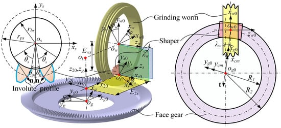
The shaper and the grinding worm are regarded as a virtual internal meshing pair [34]. The worm flank is generated by the shaper envelope and is then used to grind the target face gear flank. The same shaper envelope also defines the theoretical face gear surface [35]. For the standard involute cylindrical spur gear shaper, the surface is
In Equation (1), rbs is the shaper base-circle radius. θ0s locates the involute at the base circle. The parameters θs and uz determine the shaper surface. The upper sign is used for the left profile and the lower sign for the right profile.
The unit normal of the shaper flank is
The worm flank is obtained from the shaper envelope [36]. The coordinate systems for this process are defined in Figure 1. Ss0 and Ss belong to the shaper, while Sw0 and Sw belong to the worm. The resulting worm surface rw is
Figure 1.
Coordinate systems for the shaper, worm, and face gear.
The worm flank normal vector is
In the equations above, fsw(θs, uz, φs) gives the shaper–worm meshing condition. is the relative velocity. φs is the shaper rotation angle, and Mws(φs) converts coordinates from Ss to Sw.
2.2. Face Gear Surface
The worm grinding process uses rotation and radial feed as independent motions. The worm and the face gear rotate with the prescribed ratio, and the worm feeds in the radial direction of the gear [37]. The feed coordinate and rotation angle are independent variables, so they form the two parameters of the generated surface [38]. Rotation determines the tooth-height profile. Radial feed expands that profile in the axial direction. With Sg0 and Sg denoting the fixed and moving systems of the face gear, and S20 denoting the transitional system, the face gear tooth surface is
Mgw transforms coordinates from Sw to Sg. The meshing condition between the grinding worm and the face gear is expressed by the tangency condition between the relative velocity and the common normal at the instantaneous contact point. In this study, the same meshing principle is written in two forms according to the prescribed parameter. When the position parameter E2s is fixed, the grinding worm rotation angle φw varies during generation, and the meshing equation is f1 = 0. Conversely, when φw is fixed, E2s is treated as the varying parameter, and the corresponding meshing equation is f2 = 0. Thus, f1 describes the contact condition along the generating motion for a given E2s, whereas f2 describes the contact condition associated with varying E2s at a specified grinding worm angular position. The corresponding velocities are and .
2.3. Grinding Worm Dressing Path
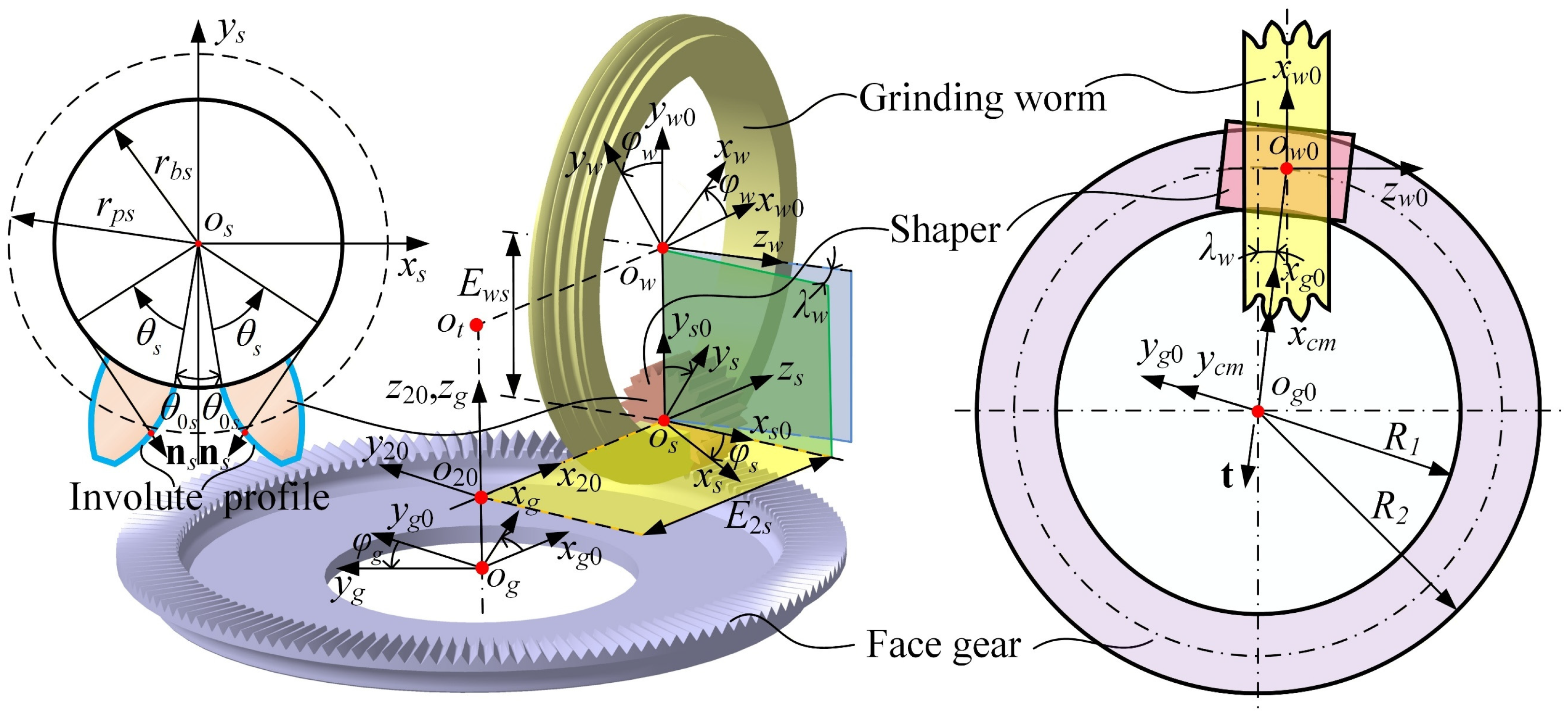
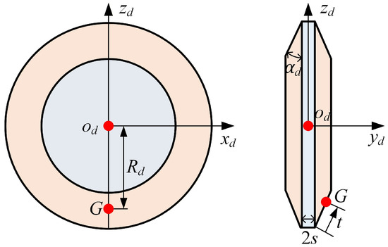
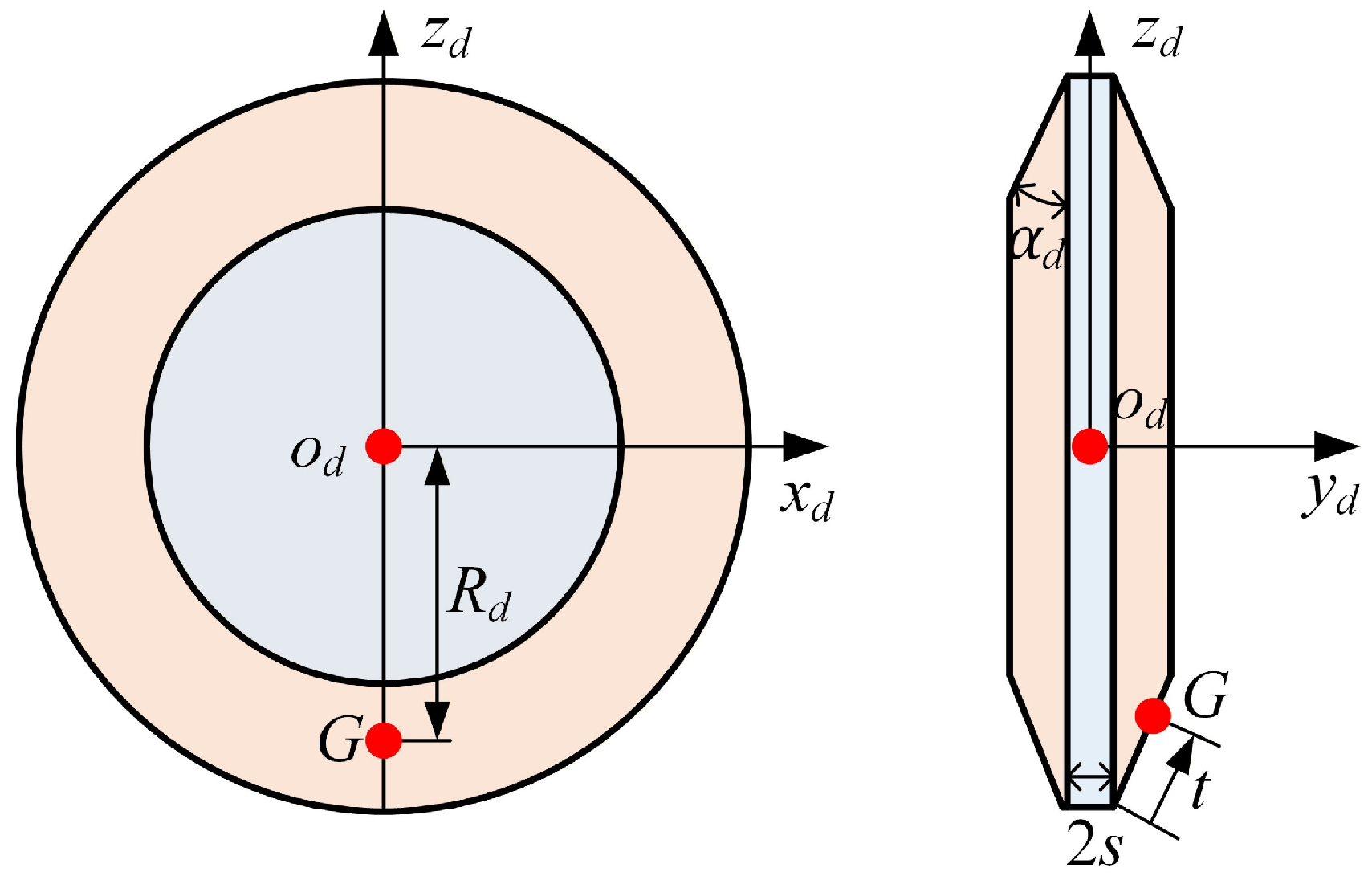
The worm is dressed by a standard conical dressing wheel [39]. Figure 2 defines the wheel by Rd, ad, s, t, and θd, which are the maximum outer radius, semi-cone angle, half tip thickness, line parameter, and rotation parameter. For a point G on the wheel surface, its vector rd and normal nd in SG are
Figure 2.
Parameters of the conical dressing wheel.
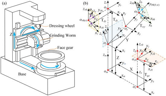
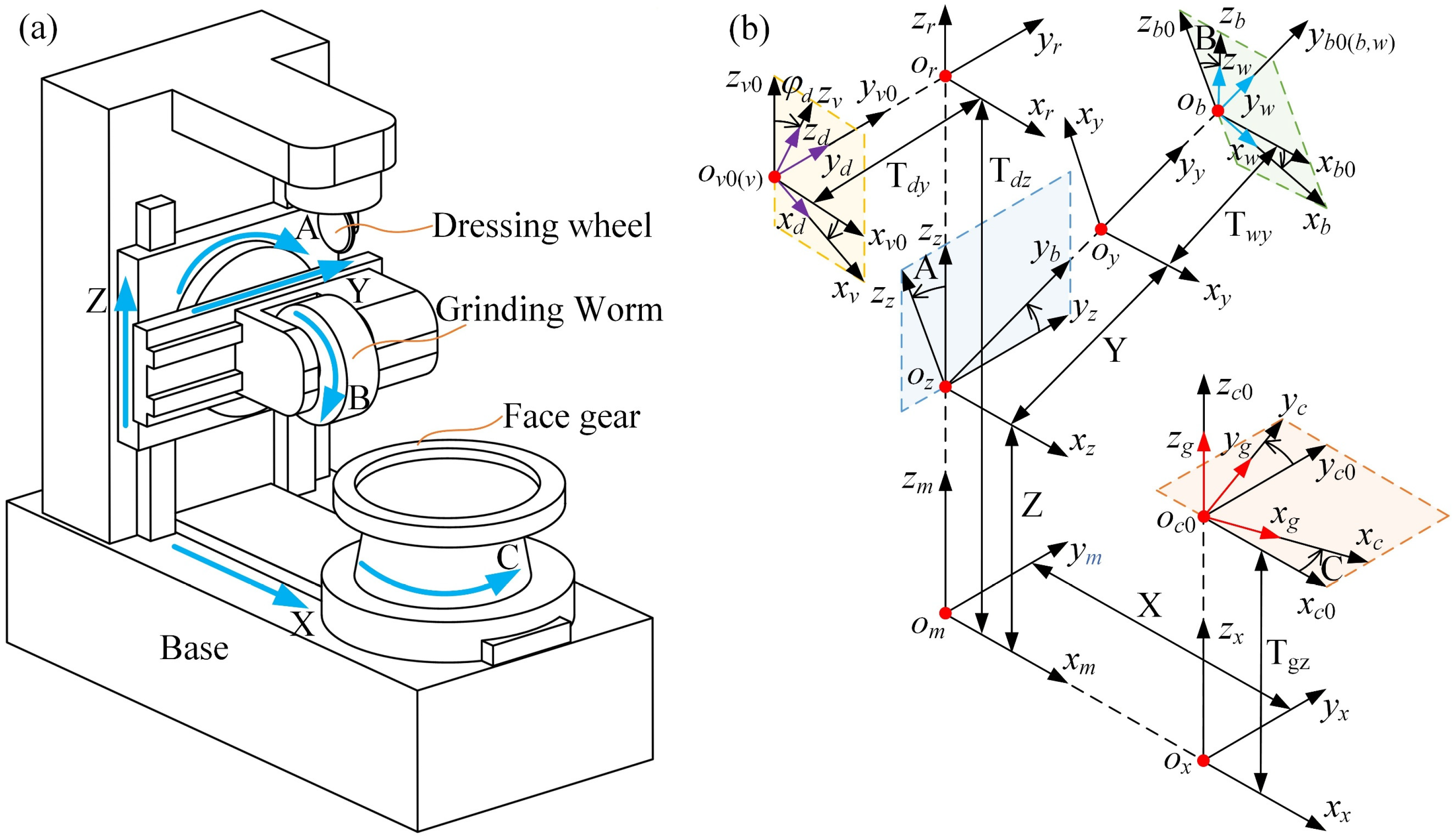
The CNC grinder is illustrated in Figure 3a. It has translational axes X, Y, and Z and rotary axes A, B, and C. Sv is fixed to the grinding worm, Sb to the dressing wheel, Sc to the face gear, and Sm to the machine frame, as shown in Figure 3b. B is the actual worm rotation about its axis. φw is the generation parameter in the worm surface equation and is not equal to B. During dressing, B also describes the relative wheel–worm motion. C is the rotation of the face gear. All wheel and worm vectors are transformed into Sm for path calculation.
Figure 3.
CNC grinder and coordinate systems: (a) machine layout and (b) system definition.
At a dressing contact point, the wheel and worm surfaces are tangent. The contact equation is
The solution is obtained by assigning discrete values to A. The values of Y, Z, and B are then solved for each assigned A. One solution gives one helical trace on the worm flank, and the collection of traces defines the dressed worm surface.
2.4. Grinding Path of Face Gear
In face gear grinding, the A-axis is held at 0°. The B-axis and C-axis are coupled to keep the worm and gear in mesh [40]. The X-axis and Y-axis also move as a linked pair. The Z-axis is regarded as an independent variable, and its nominal value is determined prior to the coordinated machining process. The machine path is
In Equation (10), φw and φg denote the worm and gear rotations. iwg is the transmission ratio. λw is the worm-axis offset angle. E2s is the distance from the shaper middle plane to the gear axis, and Ews is the distance from the worm axis to the gear axis. Twy is the offset from the worm system to the Y-axis zero position. Tgz is the distance from the gear system to Sm. s is the radial feed, mn is the shaper normal module, and Ns is the shaper tooth number. These quantities determine the actual machined face gear surface on the CNC grinder.
3. Pitch and Tooth Thickness Deviation
3.1. Pitch Deviation
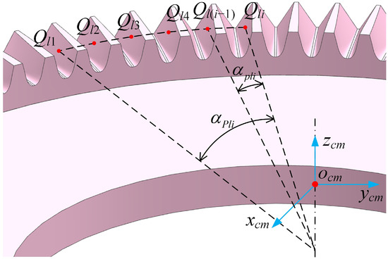
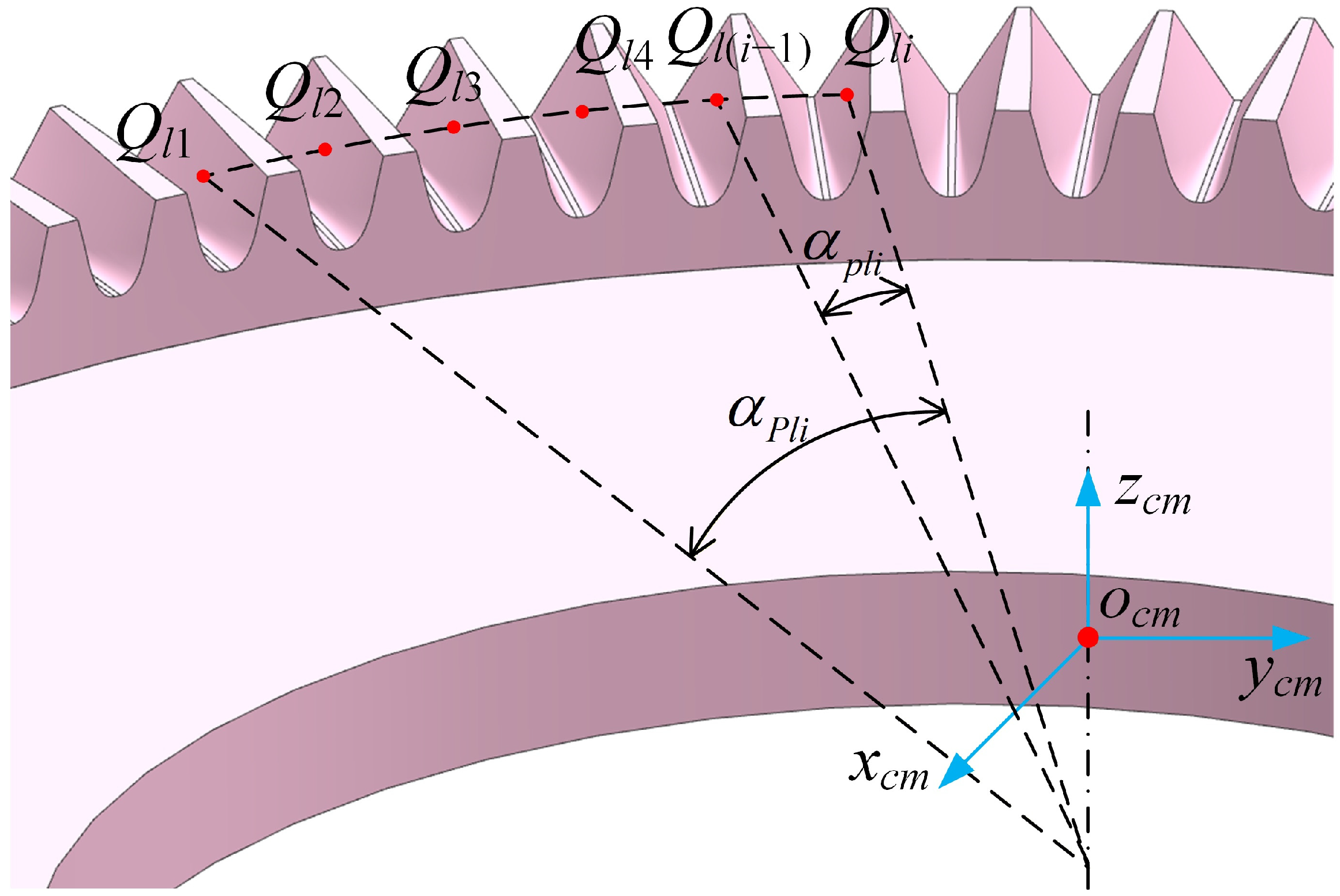
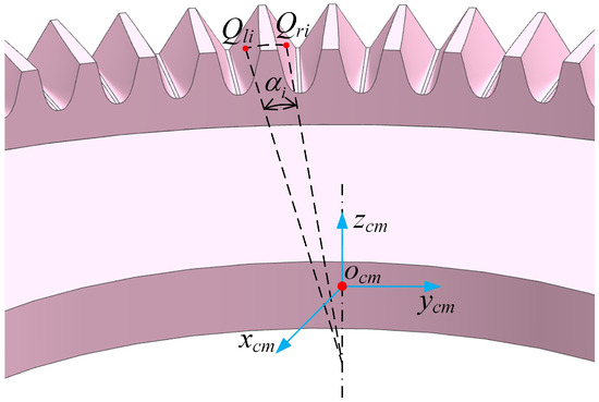
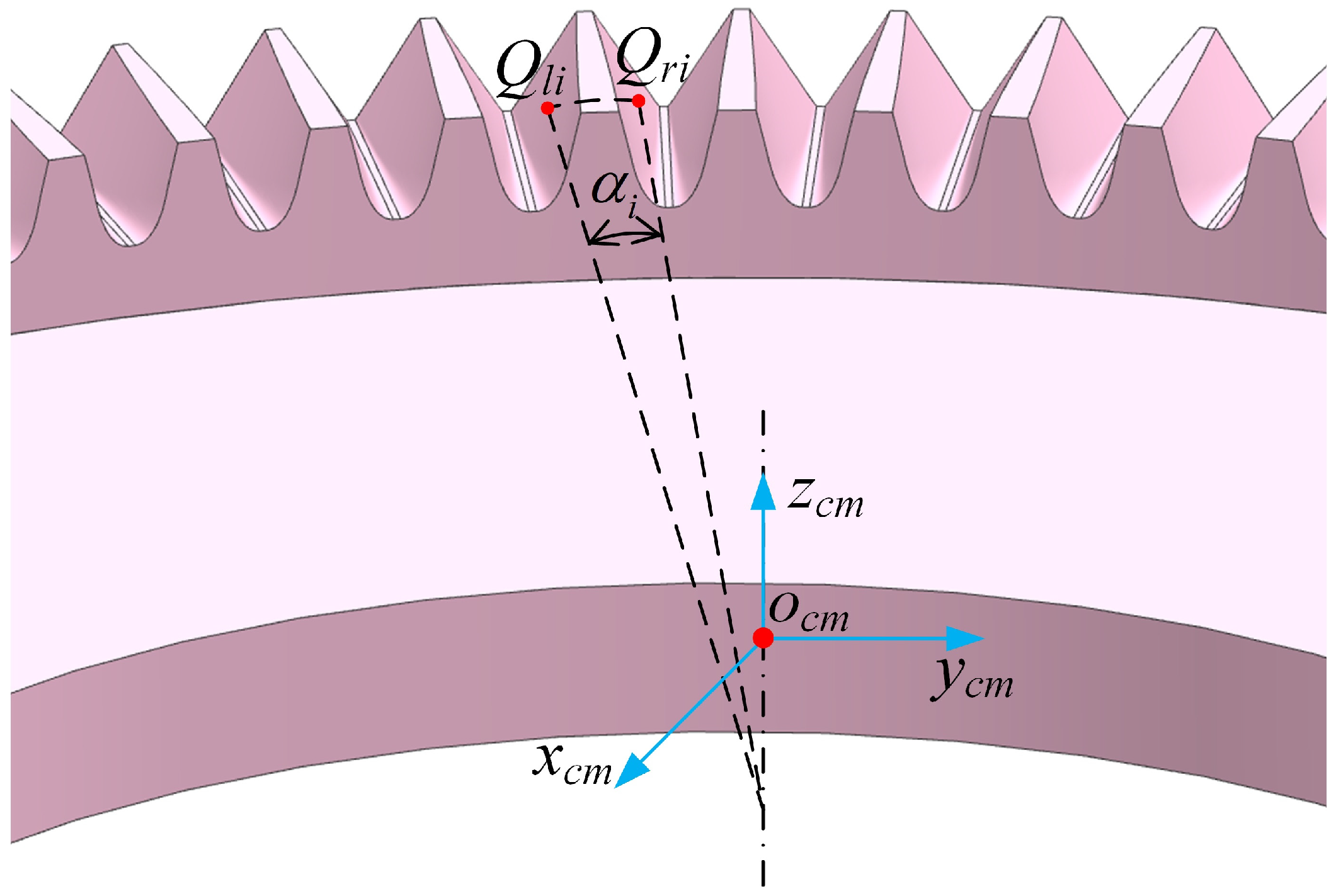
The single pitch error for a face gear is evaluated between two adjacent teeth on the same flank [41]. The nominal pitch is compared with the measured pitch at the flank midpoint, as shown in Figure 4. For the left flank, the measured points Ql(i−1) and Qli are
Figure 4.
Measurement definition of pitch deviation.
The left single pitch deviation fpl is calculated as the measured arc length minus the nominal arc length:
The corresponding included angle αli is
The radial coordinate in the pitch calculation is
Rmin and Rmax are the inner and outer radii of the gear. R is selected as the mean value of Rmin and Rmax [41].
Cumulative pitch deviation is obtained by summing same-side pitch errors over candidate arc segments and taking the maximum absolute result [41]. For the left flank, the index is
The right-flank indices fpr and fPr are obtained by the same operation.
In the CMM measurement procedure, the theoretical pitch positions are first used as the nominal measurement locations. The probe then measures the actual points on the face gear tooth surface corresponding to these theoretical locations. Based on these actual measurement points, the measured arc length is calculated. The nominal arc length is obtained from the theoretical tooth geometry at the same measurement positions.
3.2. Tooth Thickness Deviation
Figure 5 gives the measurement definition for tooth thickness [41]. The measurement point is again the flank midpoint. Pli and Pri denote nominal points on the left and right flanks, and Qli and Qri denote the measured points. The coordinate expressions for Pli, Pri, and Qri are
Figure 5.
Measurement definition of tooth thickness error.
The tooth thickness error is
The measured and nominal tooth thicknesses are tai and tti. They are evaluated by
4. Pitch and Tooth Thickness Compensation
4.1. Pitch Deviation Compensation
The machine controller supports linkage polynomials up to the sixth order. A high-order term is inserted into the grinding command, so pitch error can be adjusted by changing the trajectory.
The polynomial coefficients are
and with the correction term, the generated surface is
The corrected surface is combined with the pitch error model to obtain the residual cumulative errors and . The relation between the original measured error and the residual error is
The optimization target for pitch correction is
During the compensation of pitch and tooth thickness errors, constraints should be imposed on the tooth surface deviation, which can be expressed as
where ng is the unit normal vector of the theoretical face gear tooth surface.
Pitch deviation compensation and tooth thickness deviation compensation are applied simultaneously in this study. The pitch deviation and tooth thickness deviation are treated as independent error components. Pitch deviation describes the relative positional error between adjacent teeth, while tooth thickness deviation describes the deviation between the left and right flanks of a single tooth. In the compensation of tooth thickness, the same compensation amount is applied to the corresponding tooth flanks of the face gear, so that the flanks on the same side increase or decrease synchronously. As a result, the relative pitch spacing between adjacent teeth remains unchanged, and the tooth thickness compensation does not affect the pitch deviation.
The nonlinear optimisation problem is solved using the Levenberg–Marquardt (L-M) algorithm. The nominal machine-setting parameters before compensation are used as the initial values. The iteration process is stopped when the variation in the objective function or compensation variables is less than the specified convergence tolerance, or when the maximum number of iterations is reached. The convergence tolerance is set as 1 μm, the maximum number of iterations is 1000, and the allowable profile deviation threshold is 1 μm. During the optimisation, the tooth profile accuracy is constrained according to the mathematical tooth surface model given above. The compensated tooth surface is compared with the theoretical tooth surface, and the solution is accepted only when the calculated profile deviation is within the allowable threshold.
4.2. Tooth Thickness Deviation Compensation
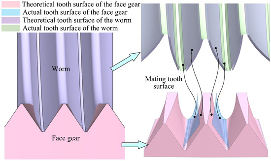
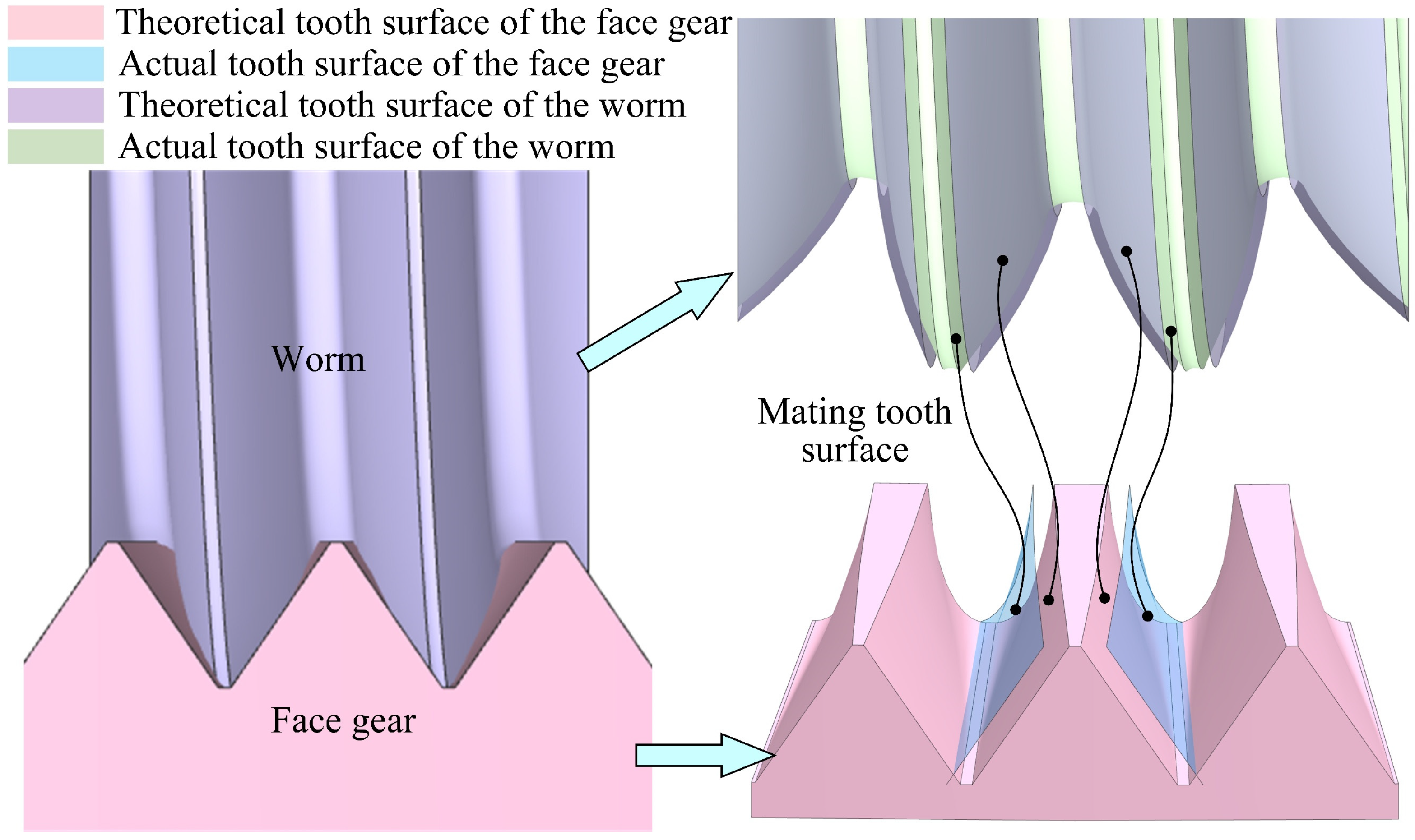
The machined tooth thickness depends on the effective worm tooth thickness. When the measured gear tooth is thicker than the target value, the worm tooth thickness is reduced. When the measured gear tooth is thinner, the worm tooth thickness is increased. Figure 6 shows the adjustment rule. The worm flank is reconstructed after this thickness correction.
Figure 6.
Worm flank reconstruction for tooth thickness correction.
The transformation matrix is
The angle φb is
Substitution of this relation gives the dressing path for the corrected worm. The face gear machined by this worm reaches the required tooth thickness.
5. Grinding Experiment
The correction model was tested on a CNC face gear grinder. The experiment compared the pitch error and tooth thickness error before and after compensation. In the grinding process of the face gear, the grinding wheel speed was set to 2000 r/min, the radial feed rate was 15 mm/min, and the material removal depth per pass was 0.01 mm. The grinding wheel was a 5SG wheel with an outer diameter of 345 mm, and emulsion was used as the coolant. Table 1 presents the parameters of three face gears, which are denoted by Gear 1, Gear 2, and Gear 3. The iterative processes for Gear 1, Gear 2, and Gear 3 reached convergence after 245, 132, and 128 iterations, respectively.
Table 1.
Face gear parameters for machining experiment.
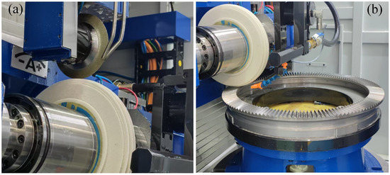
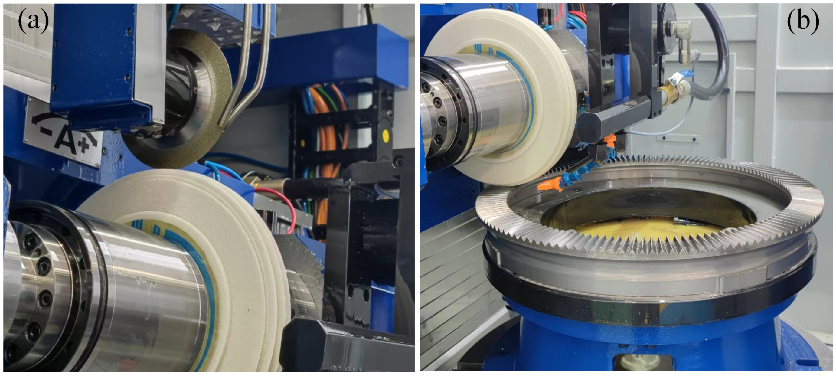
The machining sequence had two steps. First, the dressing wheel generated the worm surface. Second, the dressed worm ground the face gear, as shown in Figure 7. Gears were produced by preliminary grinding and inspected on a Leitz PMM-C coordinate measuring machine before compensation.
Figure 7.
Machining sequence: (a) worm dressing and (b) face gear grinding.
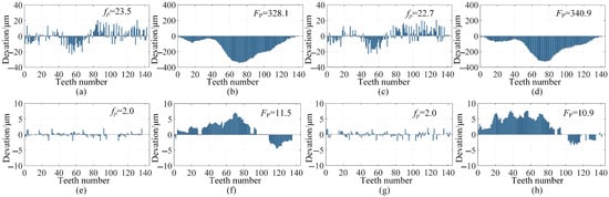
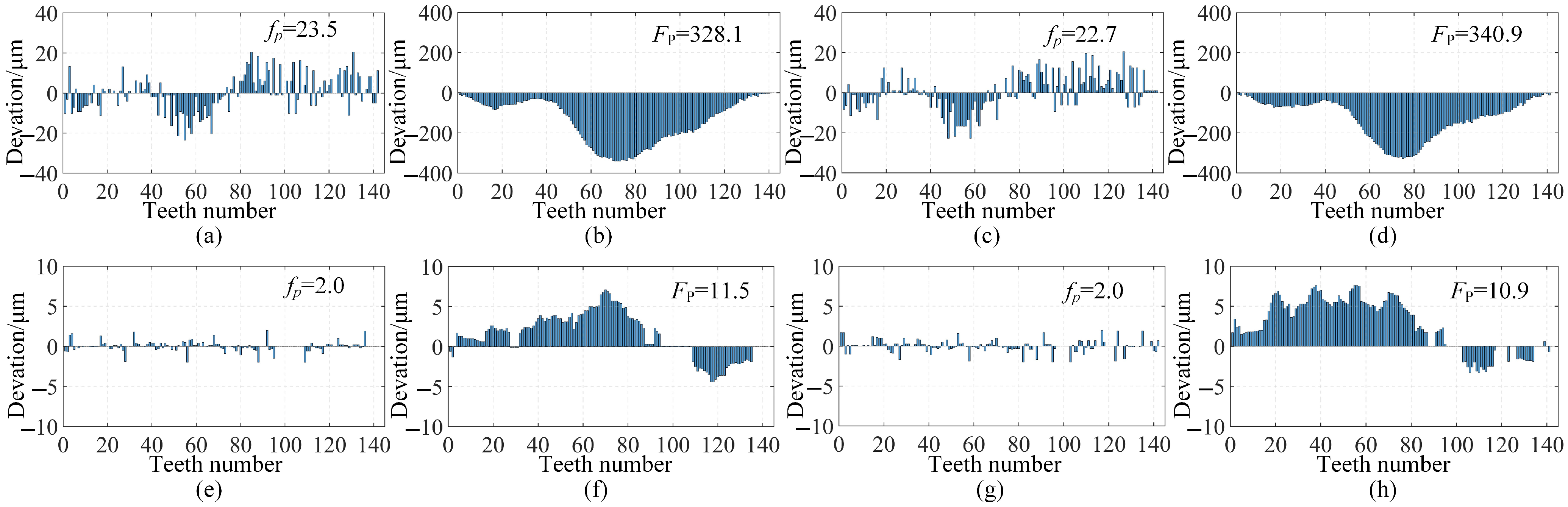
Before compensation for Gear 1, the left flank had a maximum pitch error of 23.5 μm and a cumulative pitch error of 328.1 μm. On the right flank, the two values were 22.7 μm and 340.9 μm. The tooth thickness error was 49.5 μm. After compensation, Gear 1 was ground again and remeasured. The left-flank maximum pitch error was 2 μm, and the cumulative pitch error was 11.5 μm, as shown in Figure 8. The right-flank values were 2 μm and 10.9 μm. The tooth thickness error was reduced to 10.4 μm. The maximum pitch error decreased by 21.5 μm on the left flank and by 20.7 μm on the right flank. The cumulative pitch error decreased by 316.6 μm and 330 μm on the left and right flanks, respectively. The tooth thickness error decreased by 39.1 μm, as shown in Table 2. According to the AGMA 2009-B01 measurement standard, before compensation, the individual pitch accuracy of the face gear was Grade 7, and the cumulative pitch accuracy was Grade 12. After compensation, both the individual pitch accuracy and cumulative pitch accuracy were improved to Grade 3.
Figure 8.
Pitch deviations of Gear 1. Before compensation: (a) individual and (b) cumulative pitch deviations on the left flank; (c) individual and (d) cumulative pitch deviations on the right flank. After compensation: (e) individual and (f) cumulative pitch deviations on the left flank; (g) individual and (h) cumulative pitch deviations on the right flank.
Table 2.
Pitch and tooth thickness error reductions.
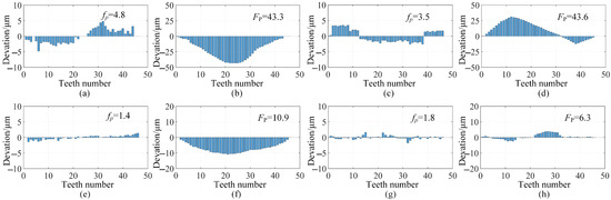
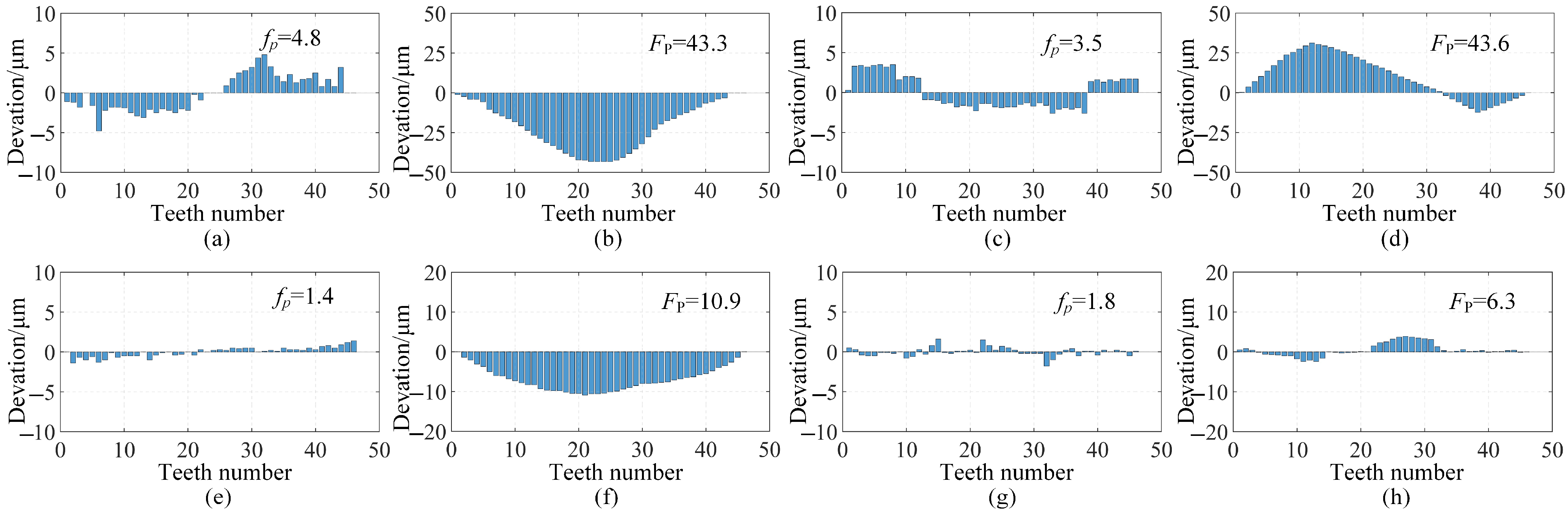
Before compensation for Gear 2, the left flank had a maximum pitch error of 4.8 μm and a cumulative pitch error of 43.3 μm. On the right flank, the two values were 3.5 μm and 43.6 μm. The tooth thickness error was 40.0 μm. After compensation, Gear 2 was ground again and remeasured. The left-flank maximum pitch error was 1.4 μm, and the cumulative pitch error was 10.9 μm, as shown in Figure 9. The right-flank values were 1.8 μm and 6.3 μm. The tooth thickness error was reduced to 9.2 μm. The maximum pitch error decreased by 3.4 μm on the left flank and by 1.7 μm on the right flank. The cumulative pitch error decreased by 32.4 μm and 37.3 μm on the left and right flanks, respectively. The tooth thickness error decreased by 30.8 μm, as shown in Table 2. The individual pitch accuracy and cumulative pitch accuracy of the face gear were Grade 4 and Grade 6 before compensation, respectively. After compensation, both were improved to Grade 3.
Figure 9.
Pitch deviations of Gear 2. Before compensation: (a) individual and (b) cumulative pitch deviations on the left flank; (c) individual and (d) cumulative pitch deviations on the right flank. After compensation: (e) individual and (f) cumulative pitch deviations on the left flank; (g) individual and (h) cumulative pitch deviations on the right flank.
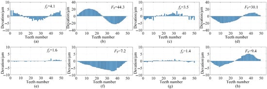
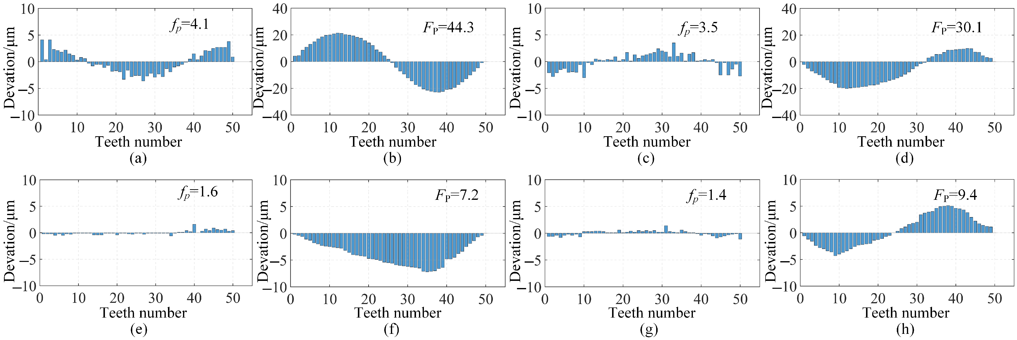
Before compensation for Gear 3, the left flank had a maximum pitch error of 4.1 μm and a cumulative pitch error of 44.3 μm. On the right flank, the two values were 3.5 μm and 30.1 μm. The tooth thickness error was 39.7 μm. After compensation, Gear 3 was ground again and remeasured. The left-flank maximum pitch error was 1.6 μm, and the cumulative pitch error was 7.2 μm as shown in Figure 10. The right-flank values were 1.4 μm and 9.4 μm. The tooth thickness error was reduced to 8.8 μm. The maximum pitch error decreased by 2.5 μm on the left flank and by 2.1 μm on the right flank. The cumulative pitch error decreased by 37.1 μm and 20.7 μm on the left and right flanks, respectively. The tooth thickness error decreased by 30.9 μm, as shown in Table 2. The individual pitch accuracy and cumulative pitch accuracy of the face gear were Grade 4 and Grade 6 before compensation, respectively. After compensation, both were improved to Grade 3.
Figure 10.
Pitch deviations of Gear 3. Before compensation: (a) individual and (b) cumulative pitch deviations on the left flank; (c) individual and (d) cumulative pitch deviations on the right flank. After compensation: (e) individual and (f) cumulative pitch deviations on the left flank; (g) individual and (h) cumulative pitch deviations on the right flank.
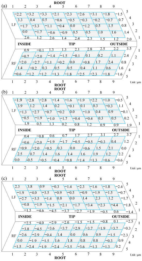
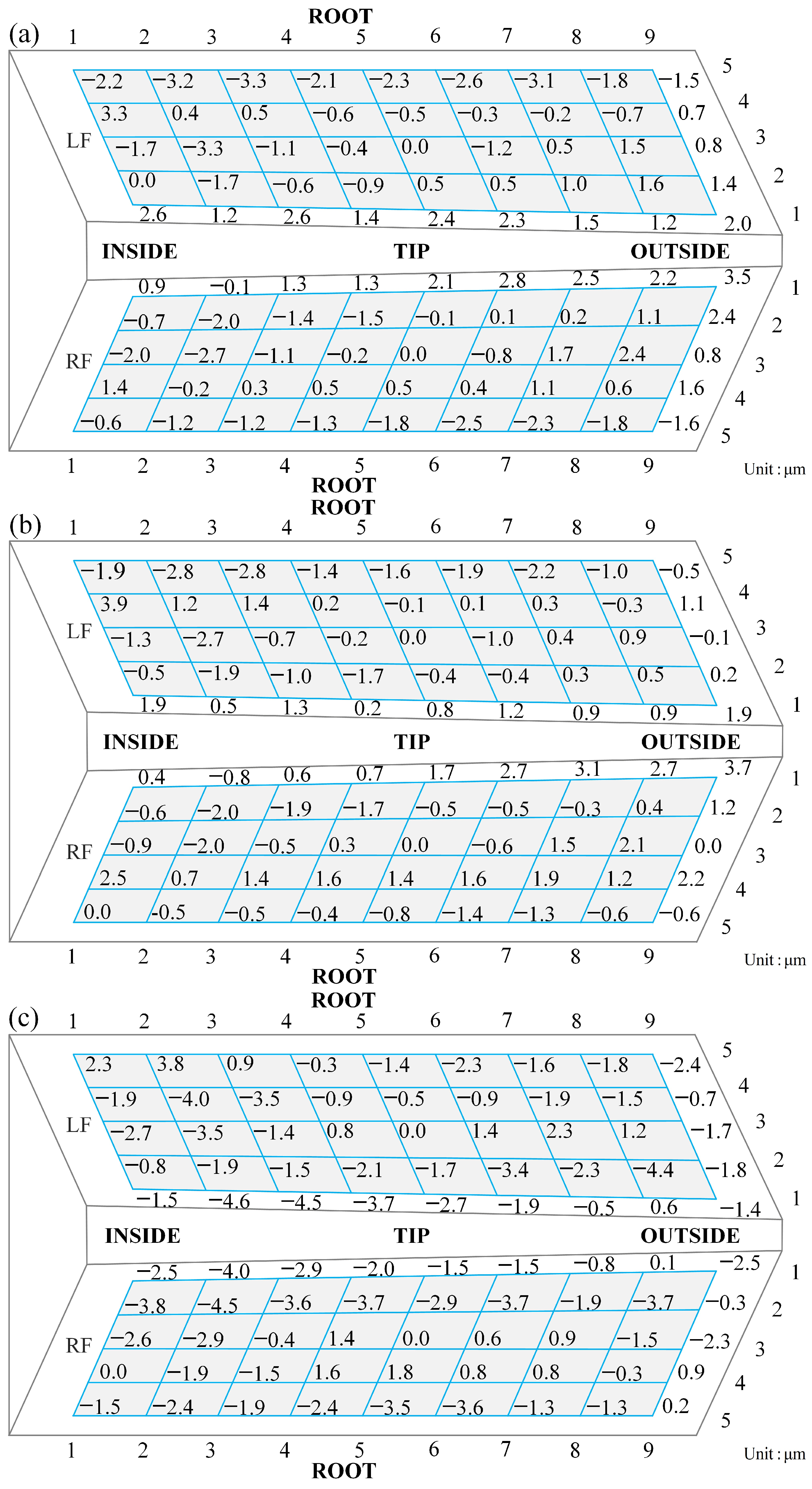
Thus, the same correction model reduced both pitch error and tooth thickness error in the grinding test. Meanwhile, the tooth profile error of the face gear remains well controlled, as shown in Figure 11.
Figure 11.
Tooth profile measurement results for face gears: (a) Gear 1, (b) Gear 2 and (c) Gear 3.
6. Conclusions
This paper proposed a compensation method for pitch and tooth thickness deviations in face gear grinding. The main contributions and conclusions are summarized as follows.
(1) Based on the structural configuration of a CNC face gear grinding machine, the dressing path of the grinding worm using the dressing wheel was planned. In addition, the grinding path of the face gear generated by the grinding worm was established.
(2) An evaluation method for the pitch and tooth thickness errors of the face gear was proposed. The pitch deviation was characterized by both single pitch deviation and cumulative pitch deviation, providing a basis for subsequent error compensation.
(3) A compensation method for pitch and tooth thickness deviations of the face gear was developed. The linkage polynomial method of the CNC machine tool was used to plan the face gear grinding path, thereby compensating for the pitch deviation. Furthermore, a meshing tooth surface mapping method between the grinding worm and the face gear was employed to compensate for the tooth thickness deviation.
(4) Compensation experiments for pitch and tooth thickness deviations of the face gear were conducted. The results showed that both the pitch error and tooth thickness deviation were effectively reduced, verifying the effectiveness of the proposed method.
(5) Pitch deviation and tooth thickness deviation are independent of each other; therefore, tooth thickness deviation compensation does not affect pitch error. During tooth thickness compensation of the face gear, each tooth flank is compensated by the same amount, and the tooth flanks on the same side increase or decrease synchronously. Accordingly, pitch deviation and tooth thickness deviation can be compensated either simultaneously or separately.
It should be noted that the proposed method has only been applied to unmodified spur face gears. For modified face gears or helical face gears, interference may occur between the grinding worm and the face gear tooth surface during pitch and tooth thickness compensation, which may further affect the compensation performance.
Author Contributions
Conceptualization, H.H.; Methodology, H.H.; Software, C.L.; Validation, H.H.; Formal analysis, C.L.; Investigation, H.H.; Resources, Y.Z.; data curation, C.L.; Writing—original draft preparation, H.H. and Y.Z.; Writing—review & editing, H.H. and Y.Z.; Visualization, Y.Z.; Supervision, Y.Z. and J.T.; Project administration, Y.Z. and J.T.; Funding acquisition, Y.Z. and J.T. All authors have read and agreed to the published version of the manuscript.
Funding
This research was funded by the National Natural Science Foundation of China, Grant number U22B2086 and 52575084, Central South University Innovation-Driven Research Program, Grant number 2023CXQD050, the Industry University Research Cooperation Project of China Aviation Engine Group Co., Ltd., under Grant, Grant number HFZL2024CXY020.
Data Availability Statement
The original contributions presented in this study are included in the article. Further inquiries can be directed to the corresponding author.
Conflicts of Interest
The authors declare that the research was conducted in the absence of any commercial or financial relationships that could be construed as a potential conflict of interest.
References
- Litvin, F.L.; Gonzalez-Perez, I.; Fuentes, A.; Vecchiato, D.; Hansen, B.D.; Binney, D. Design, generation and stress analysis of face-gear drive with helical pinion. Comput. Methods Appl. Mech. Eng. 2005, 194, 3870–3901. [Google Scholar] [CrossRef] [Scilit]
- Litvin, F.L.; Fuentes, A.; Howkins, M. Design, generation and TCA of new type of asymmetric face-gear drive with modified geometry. Comput. Methods Appl. Mech. Eng. 2001, 190, 5837–5865. [Google Scholar] [CrossRef] [Scilit]
- Jia, C.; Liu, C.; Yao, L.; Mu, Y.; Fang, Z. An investigation on the lubrication characteristics of asymmetric helical face gear drives An emphasis on balance between pressure angle and contact ratio. Tribol. Int. 2026, 217, 111683. [Google Scholar] [CrossRef] [Scilit]
- Mo, S.; Luo, B.; Song, W.; Zhang, Y.; Cen, G.; Bao, H. Geometry design and tooth contact analysis of non-orthogonal asymmetric helical face gear drives. Mech. Mach. Theory 2022, 173, 104831. [Google Scholar] [CrossRef] [Scilit]
- Xu, B.; Zhu, L.; Gou, X.; Chai, C.; Liu, G.; Zhao, X.; Chen, M.; Liu, Z.; Liu, C.; Liang, D.; et al. Real-time direct measurement and calculation of tooth flank contact temperature for point contact spur-face gear drive. Int. J. Heat Fluid Flow 2026, 120, 110405. [Google Scholar] [CrossRef] [Scilit]
- Le, K.; Wu, Y. Face-gear drive with novel tooth flanks: High-precision CNC skiving simulation and tooth contact analysis. Precis. Eng. 2026, 99, 516–533. [Google Scholar] [CrossRef] [Scilit]
- Mo, S.; Song, W.; Zhu, S.; Feng, Z.; Tang, W.; Gao, H. Complex geometric modeling and tooth contact analysis of a helical face gear pair with arc-tooth. J. Cent. South Univ. 2022, 29, 1213–1225. [Google Scholar] [CrossRef] [Scilit]
- Wang, S.; Ma, Y.; Xiao, Y.; Zhang, L.; Xia, M.; Wang, S. Improved loaded tooth contact analysis model for face gear drives. Appl. Math. Model. 2026, 157, 116877. [Google Scholar] [CrossRef] [Scilit]
- Liu, L.; Wu, S.; Wang, X. Generation and contact of modified non-orthogonal offset face gear drives. Int. J. Mech. Sci. 2025, 300, 110314. [Google Scholar] [CrossRef] [Scilit]
- Xu, Y.; Yang, J.; Gu, R.; Jiang, C.; Deng, J. Numerical Prediction Modeling for Fatigue Experiments on Straight Face Gears Produced via Hot Rolling with Insufficient Information. Machines 2026, 14, 444. [Google Scholar] [CrossRef] [Scilit]
- Wang, S.; Zhou, Y.; Tang, J.; Tang, K.; Li, Z. Digital tooth contact analysis of face gear drives with an accurate measurement model of face gear tooth surface inspected by CMMs. Mech. Mach. Theory 2022, 167, 104498. [Google Scholar] [CrossRef] [Scilit]
- Ma, X.; Cai, Z.; Li, J.; Li, Z.; Li, Z.; Gao, S. Prediction method for residual stress in face gear generating grinding based on a unified thermo-mechanical computational unit with discrete grains. J. Manuf. Process. 2025, 141, 865–884. [Google Scholar] [CrossRef] [Scilit]
- Mu, S.; Yang, Y.; Sun, X.; Dong, Z.; Yan, F.; Liu, Y.; Qu, S.; Pan, F.; Zhang, W.; Zhao, Y. Meshing principle of a constant-transmission ratio hybrid-mismatch conical-surface-enveloping cylindrical worm-Archimedean face worm gear drive. Mech. Mach. Theory 2026, 226, 106493. [Google Scholar] [CrossRef] [Scilit]
- Mo, S.; Song, W.; Zhang, Y.; Yao, B.; Chen, S.; Huang, Y.; Shi, W.; Peng, N.; Houjoh, H.; Zhang, W. An improved modeling and solution method for point contact elastohydrodynamic lubrication of face gear pairs. Tribol. Int. 2026, 214, 111247. [Google Scholar] [CrossRef] [Scilit]
- Mo, S.; Song, W.; Liu, Y.; Zhang, L.; Chen, S.; Man, X.; Hu, W.; Peng, N.; Zhang, W. Coupled modeling of meshing stiffness and mixed elastohydrodynamic lubrication in asymmetric face gear pairs. Tribol. Int. 2026, 222, 112059. [Google Scholar] [CrossRef] [Scilit]
- Ma, X.; Cai, Z.; Yao, B.; Chen, G.; Cai, S.; Liu, W. Prediction model for surface generation mechanism and roughness in face gear grinding. Int. J. Adv. Manuf. Technol. 2022, 120, 4423–4442. [Google Scholar] [CrossRef] [Scilit]
- Li, G.; Wang, Z.; He, K.; Pu, Z.; Zhang, B. Dressing method of worm wheels for grinding face gears based on the principle of virtual phase transition. Int. J. Adv. Manuf. Technol. 2024, 131, 5831–5843. [Google Scholar] [CrossRef] [Scilit]
- Zhou, Y.; Tang, Z.; Shi, X.; Tang, J.; Li, Z. Efficient and accurate worm grinding of spur face gears according to an advanced geometrical analysis and a closed-loop manufacturing process. J. Cent. South Univ. 2022, 29, 1–13. [Google Scholar] [CrossRef] [Scilit]
- Guo, H.; Zhao, N.; Zhang, S.; Zhou, R. Dressing Method with Fewer CNC Axes for Face Gear Grinding Worm with Standard Cone Dressing Wheel. J. Mech. Eng. 2017, 53, 23–29. [Google Scholar] [CrossRef] [Scilit]
- Yan, Y.; Guo, H.; Gu, J.; Zhao, N.; Liu, L. Computerized generation, deviation correction and rapid tooth contact analysis of helical face gear. Mech. Mach. Theory 2024, 203, 105789. [Google Scholar] [CrossRef] [Scilit]
- Xia, M.; Wang, S.; Dong, J.; Xiao, Y.; Kong, W.; Wang, S. A two-stage flank correction method for the continuous generation of face gears. J. Manuf. Process. 2024, 120, 756–777. [Google Scholar] [CrossRef] [Scilit]
- Wang, S.; Xia, M.; Ma, C.; Dong, J.; Wang, S.; Wang, J. A novel flank correction method for face gear ground by CNC worm wheel grinder. Mech. Mach. Theory 2023, 189, 105435. [Google Scholar] [CrossRef] [Scilit]
- Tang, Z.; Zhou, Y.; Wang, S.; Zhu, J.; Tang, J. An innovative geometric error compensation of the multi-axis CNC machine tools with non-rotary cutters to the accurate worm grinding of spur face gears. Mech. Mach. Theory 2022, 169, 104664. [Google Scholar] [CrossRef] [Scilit]
- Liu, J.; Ma, C.; Li, M.; He, J.; Totis, G.; Hua, C.; Cui, G.; Wang, L.; Xue, R.; Tan, Z.; et al. A compressed tensor-based edge-deployable framework for multi-source thermal error compensation in face gear machining. Adv. Eng. Inform. 2025, 68, 103802. [Google Scholar] [CrossRef] [Scilit]
- Ma, C.; You, D.; Liu, J.; Li, M.; He, J.; Totis, G. Topology optimization of cooling elements for worm wheel gear grinding machine tool bed under non-uniform heat sources. Appl. Therm. Eng. 2025, 281, 128739. [Google Scholar] [CrossRef] [Scilit]
- Li, G.; Pu, Z.; He, K.; Wang, Z.; Ning, H.; Zhang, W. Analysis and compensation of installation error of face gear by worm wheel grinding. Comput. Integr. Manuf. Syst. 2025, 31, 452–463. [Google Scholar] [CrossRef]
- Wang, J.; Wang, S.; Ma, C.; Xia, C. Crucial errors identification of worm grinding process of face gears based on tooth flank posture error model and their influences on tooth flank errors. Int. J. Adv. Manuf. Technol. 2022, 119, 6177–6192. [Google Scholar] [CrossRef] [Scilit]
- Wang, J.; Wang, S.; Ma, C.; Wang, S.; Dong, J.; Yang, Y. Identification of crucial geometric errors of face gear grinding machine based on geometric error-tooth surface normal error model considering worm dressing. Mech. Mach. Theory 2022, 176, 105036. [Google Scholar] [CrossRef] [Scilit]
- Yang, H.; Huang, X.; Guo, E. Analysis and Compensation for Pitch Error in Forming Manufacturing Big Gears. Modul. Mach. Tool Autom. Manuf. Tech. 2018, 10, 59–63. [Google Scholar] [CrossRef] [Scilit]
- Zhai, Y.; Guo, X.; Wang, Q. Research on Pitch Error Analysis and Compensation of Large Gear Based on Cross Tooth Indexing Method. Mach. Tool Hydraul. 2022, 50, 49–54. [Google Scholar]
- Zhen, G.; Lian, X.; Jiang, H. Research on pitch error compensation of non-circular gear in electronic gearbox. J. Hefei Univ. Technol. Nat. Sci. 2023, 46, 157–161. [Google Scholar]
- Zhang, M.; Deng, X.; Su, J. Influence of Eccentricity on the Forming Grinding of Cycloidal Gear and Its Compensation. J. Mech. Transm. 2021, 45, 12–18. [Google Scholar]
- Zhang, K.; He, D.; Wang, J.; Lao, Q.; Zeng, L.; Yang, C. Research on Compensation Method of Gear Pitch Error in Hobbing Process Based on Harmonic Decomposition. Tool Eng. 2019, 53, 124–129. [Google Scholar]
- Li, Z.; Fan, J.; Zhu, R. Construction of Tooth Modeling Solutions of Face Gear Drives with an Involute Pinion. Iran. J. Sci. Technol.-Trans. Mech. Eng. 2018, 42, 35–39. [Google Scholar] [CrossRef] [Scilit]
- Wang, J.; Li, Z.; Lv, C. Contact characteristics of a load-capacity-oriented modified tooth flank for face gears under assembly errors. Meccanica 2026, 61, 61–68. [Google Scholar] [CrossRef] [Scilit]
- Guo, H.; Zhang, S.; Wu, T.; Zhao, N. An approximate design method of grinding worm with variable meshing angle and grinding experiments of face gear. Mech. Mach. Theory 2021, 166, 104461. [Google Scholar] [CrossRef] [Scilit]
- Gao, S.; Ma, X.; Cai, Z.; Yao, B.; Li, Z. Prediction of surface topography in face gear grinding based on dynamic contour interferometric sampling method. Int. J. Adv. Manuf. Technol. 2024, 130, 3401–3418. [Google Scholar] [CrossRef] [Scilit]
- Wang, S.; Ren, G.; Xiao, Y.; Dong, J.; Wang, J.; Wang, T. Periodic power variation mechanism in face gear continuous generating grinding. Int. J. Mech. Sci. 2025, 303, 110654. [Google Scholar] [CrossRef] [Scilit]
- Guo, H.; Gonzalez-Perez, I.; Fuentes-Aznar, A. Computerized generation and meshing simulation of face gear drives manufactured by circular cutters. Mech. Mach. Theory 2019, 133, 44–63. [Google Scholar] [CrossRef] [Scilit]
- Yan, Y.; Guo, H.; Sun, L.; Zhao, N.; Teng, W. An approximate grinding and deviation correction method for helical face gear. Int. J. Adv. Manuf. Technol. 2024, 132, 2271–2291. [Google Scholar] [CrossRef] [Scilit]
- Wang, S.; Kong, W.; Dong, J.; Xiao, Y.; Wang, S.; Zhao, Y. Decoupling coupled errors in on-machine face gear metrology. Int. J. Mech. Sci. 2026, 313, 111346. [Google Scholar] [CrossRef] [Scilit]

Disclaimer/Publisher’s Note: The statements, opinions and data contained in all publications are solely those of the individual author(s) and contributor(s) and not of MDPI and/or the editor(s). MDPI and/or the editor(s) disclaim responsibility for any injury to people or property resulting from any ideas, methods, instructions or products referred to in the content. |
© 2026 by the authors. Licensee MDPI, Basel, Switzerland. This article is an open access article distributed under the terms and conditions of the Creative Commons Attribution (CC BY) license.