


Abstract
The disengagement of contact wires in rigid overhead contact systems (ROCS) is a critical hazard to urban rail transit, potentially causing pantograph–catenary collisions, wire breakage, and large-scale catenary failures. To investigate its mechanical mechanism and detection approach, a three-dimensional solid and flexible multibody coupled model of a rigid pantograph–catenary system was established using finite element analysis and multibody dynamics simulation. The effects of train speed, contact force fluctuation, contact wire stress concentration, and disengagement degree on pantograph–catenary dynamic behavior were analyzed. The results show that the standard deviation of contact force at overlapping spans is significantly higher than that in other sections, indicating that overlapping spans are high-risk regions for disengagement. The peak stress of the contact wire is mainly concentrated at registration points and increases with train speed, which may promote abnormal wear and local deformation of the conductor rail jaw. Field-observed environmental degradation factors, such as tunnel water leakage, corrosion, and conductive grease deterioration, may further weaken the clamping performance of the conductor rail. Hazard simulations show that disengagement at overlapping spans deteriorates current collection quality and aggravates carbon strip wear, especially at the beginning of the subsequent overlapping span. Based on onboard inspection equipment, an engineering detection route integrating area-scan imaging, three-dimensional profile scanning, and line-scan imaging is proposed to support the inspection of severe and minor disengagement defects.
1. Introduction
With the rapid development of urban rail transit, Rigid Overhead Contact Systems (ROCS) have been widely implemented in subways and underground sections due to their advantages, such as structural simplicity, high reliability, low maintenance costs, and minimal tunnel space requirements. However, in long-term operational practice, contact wire disengagement has emerged as a significant hazard threatening operational safety. Disengagement refers to the phenomenon where the contact wire partially or completely detaches from the jaw of the conductor rail under the influence of external mechanical forces or the physicochemical environment. Once disengagement occurs, it may cause minor issues such as abnormal pantograph-catenary wear and intense arcing, or in severe cases, lead to catastrophic accidents, including pantograph striking, wire breakage, and large-scale collapse of the catenary network, resulting in grave consequences for the operational safety of rail transit. Currently, research on ROCS is primarily focused on pantograph-catenary current collection performance and abnormal contact wire wear; however, systematic research on the complex failure mechanism of disengagement remains relatively scarce.
Lu [1] applied a multibody system dynamics (MBS) simulation platform to study common failures of rigid overhead contact systems and concluded that contact wire disengagement significantly impacts the contact force, readily generating severe impacts and leading to pantograph-catenary loss of contact. Lu et al. [2] used virtual prototyping technology to simulate the influence of contact wire disengagement on current collection quality and found that such failures locally excite high-frequency components above 11.5 Hz accompanied by significant energy fluctuations. Gao [3] systematically analyzed the causes of ROCS disengagement and proposed that the thermal expansion and contraction of the conductor rail and the longitudinal impact of the pantograph are the primary dynamic causes inducing disengagement. Li [4] explored ROCS disengagement failures and preventive measures and concluded that ensuring a 120 N pre-tension of the contact wire and monitoring a 50 mm displacement can effectively reduce the risk of disengagement. Guan et al. [5] reviewed the research status of ROCS globally and pointed out that fatigue failure accumulated over operational time and uneven component wear are critical factors affecting the system’s current collection reliability. Guan et al. [6] established pantograph-catenary coupled dynamic equations using numerical analysis methods and proved through simulation that abnormal changes in span length and support point stiffness significantly deteriorate dynamic performance and increase failure risks. Tian et al. [7] researched key ROCS technologies in subway active fault zones and verified through simulation and testing that an adjustable suspension structure can effectively resolve geometric deviations and disengagement hazards caused by geological movement. Yang et al. [8] developed a prediction model based on thermal equilibrium and wear mechanisms to study the uneven wear of collector strips in metro ROCS and concluded that the contact wire layout is the main factor leading to excessive wear at strip ends and confirmed that contact force plays a dominant role in wear evolution. Ren and Chen [9] experimentally evaluated the wear mechanism of rigid contact wires using a high-speed sliding electrical contact wear tester and found that the wear rate is inversely proportional to contact pressure and directly proportional to sliding speed, noting that as system stability declines, electrical wear becomes the decisive factor in total wear and failure induction. Hu et al. [10] investigated the influence of arc discharge on the temperature rise and wear behavior of ROCS collector strips using a block-on-ring wear tester and concluded that arc energy is the primary cause of crack propagation and peeling on the strip surface, identifying an inflection point where the wear rate increases sharply at 2.5 × 10⁴ J/min. Bucca and Collina [11] proposed a prediction program combining the wear map concept with dynamic simulation and found that graphite strips cause significantly less wear than copper strips, and that a reduction in contact wire mechanical tension significantly increases wear levels. Benet et al. [12] established a dynamic simulation model for ROCS overlapping spans and concluded that improper overlapping length and gradient settings trigger severe contact force fluctuations, thereby increasing the risk of disengagement and collisions. Zhi et al. [13] established a coupling model considering the entire wear life cycle based on multibody dynamics and energy dissipation theory and concluded that contact pair wear evolution causes dynamic performance to undergo three stages: stability, slow degradation, and rapid degradation, proposing the lateral distribution coefficient of contact force as a key indicator for identifying disengagement hazards. Feng et al. [14] designed and analyzed six new conductor rail structures with large moments of inertia and proved through 3D finite element simulation that increasing the cross-sectional moment of inertia significantly reduces contact wire sag, with the optimal solution reducing maximum static mid-span sag by 28.37%, thereby suppressing disengagement tendencies caused by geometric irregularities at the source.
By synthesizing existing research and conducting an in-depth investigation into the fluctuation patterns of contact force under moving loads, the evolution characteristics of internal stress within the contact wire, and the catalytic effects of environmental factors during long-term service holds significant theoretical value for preventing contact wire disengagement accidents. Concurrently, developing intelligent detection technology based on image recognition to facilitate the transition from “reactive maintenance” to “proactive prevention” is an effective measure to ensure the safe operation of rail transit. Therefore, this paper will first establish a finite element simulation platform to analyze the inducing excitations of abnormal wear and disengagement phenomena. Subsequently, a hazard analysis of disengagement will be conducted based on solid models. Finally, intelligent detection technology for contact wire disengagement based on image recognition will be investigated.
Therefore, this study focuses on the mechanical mechanism and engineering detection route of abnormal wear and contact wire disengagement in rigid overhead contact systems. Pantograph–catenary dynamic simulation, contact wire stress analysis, and onboard inspection technologies are investigated. The main contributions of this study are summarized as follows.
(1) A three-dimensional solid and flexible multibody coupled model of the rigid pantograph–catenary system was established to analyze the relationship among train speed, contact force fluctuation, contact wire stress concentration, and disengagement risk.
(2) The mechanical induction mechanism of contact wire disengagement was analyzed from the perspectives of external dynamic excitation and internal stress response of the contact wire. The overlap span and registration points were identified as high-risk regions.
(3) Simulations under different disengagement degrees and locations were conducted to investigate the influence of disengagement on contact force fluctuation, contact loss, and abnormal wear of carbon contact strips.
(4) Based on onboard inspection equipment, an engineering detection route integrating area-scan imaging, three-dimensional profile scanning, and line-scan imaging was proposed to provide a reference for field inspection of contact wire disengagement defects.
2. Analysis of the Induction Mechanism of Contact Wire Disengagement in Rigid Overhead Contact Systems
2.1. Modeling of the Rigid Pantograph-Catenary System
First, a rigid pantograph-catenary model was established using SolidWorks 2022 3D design software. Subsequently, finite element meshing for each component was performed in HyperMesh 2021, and the Modal Neutral Files were exported; meanwhile, the material properties of all model components were defined [15,16,17,18]. Finally, the model was imported into the Adams simulation environment. A translational joint was applied to the pantograph base, with the simulation displacement defined by the movement of the base.
For the rigid overhead contact system model, the Tianhai pantograph used on Beijing Subway Line 6 was selected as the research object. The Tianhai pantograph is a four-carbon-strip pantograph. The conductor rail parameters used in the simulation were based on those of a specific Beijing subway line, with a span length of 8 m and a stagger of ±200 mm. The material properties of the key components are listed in Table 1, and the masses of various parts are presented in Table 2, where the mass of the conductor rail and contact wire corresponds to a 200 m model.
Table 1.
Key material property values.
Table 2.
The mass of each component.
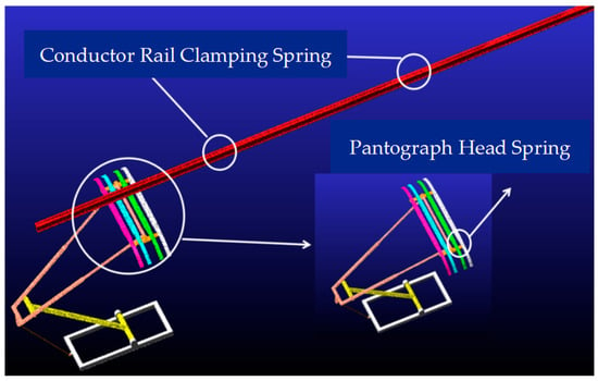
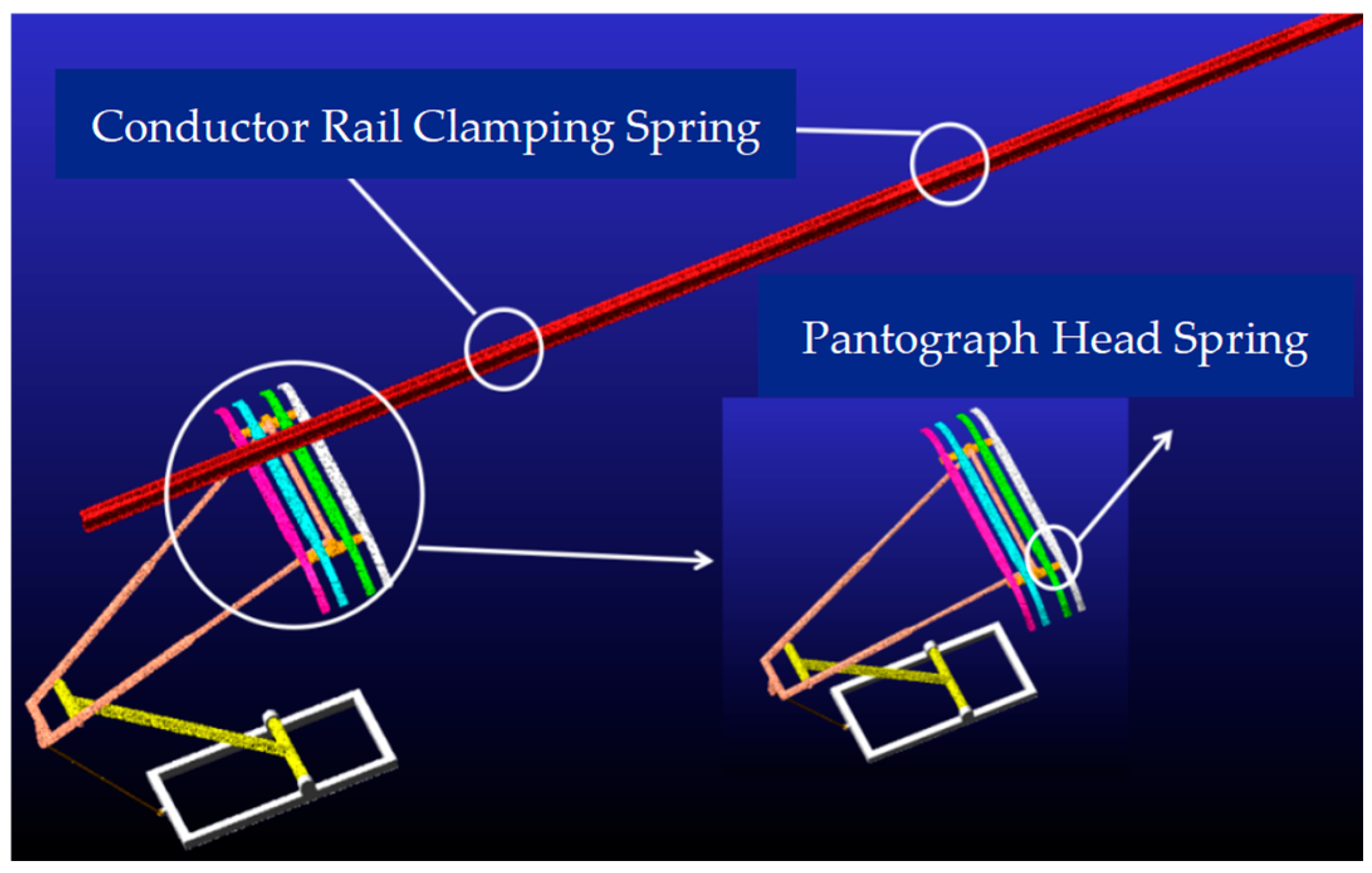
Given that the stress of the pantograph fluctuates during operation, flexible body modeling was applied to components including the collector strips, pantograph head brackets, upper and lower frames, and pull rods. The schematic diagram of the coupled pantograph-ROCS model is shown in Figure 1.
Figure 1.
Pantograph and rigid suspension catenary model.
2.2. Pantograph-Catenary Coupled Operation
Pantograph-catenary coupled operation is the core dynamic inducer of contact wire disengagement in rigid overhead contact systems (ROCS). During train operation, the dynamic interaction between the pantograph and the contact wire is not merely simple physical contact but a complex process of energy exchange and structural response. The impact of this coupling on disengagement is primarily manifested in two dimensions: external excitation and internal response.
Impact effect of dynamic contact force: With the increase in operational speed, the fluctuations of the dynamic contact force applied by the pantograph to the contact wire intensify significantly, leading to a concurrent rise in its standard deviation and peak values. Such violent pressure fluctuations generate powerful instantaneous impact forces when passing through areas of stiffness mutation, such as registration points or span joints. These forces can reach or even exceed the mechanical clamping limit of the conductor rail on the contact wire.
Evolution of internal stress in the contact wire: As a moving load sliding at high speed along the contact wire, the pantograph causes instantaneous stress concentration and alternating cycles within the wire’s internal structure. Long-term exposure to alternating stress not only induces material fatigue but also leads to irreversible micro-deformation of the conductor rail jaw under dynamic loads, thereby gradually weakening its clamping capability.
2.2.1. Contact Force Fluctuations and Abnormal Wear
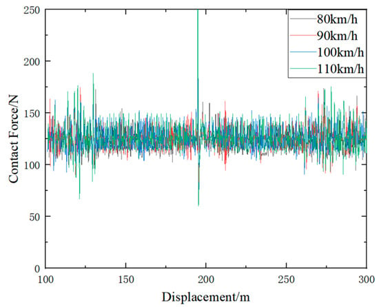
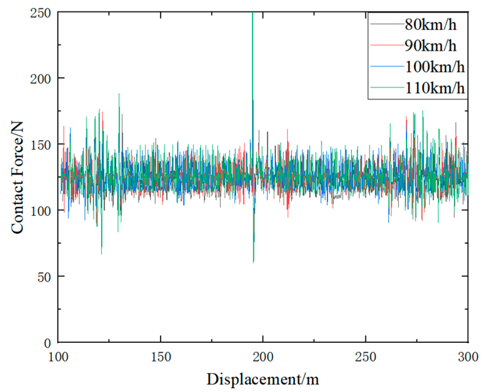
The presence of special structures, such as intermediate joints and overlapping spans, leads to variations in the stiffness uniformity of the overhead contact system and the smoothness of the contact wire. Particularly as the operational speed of metro vehicles increases, the fluctuations in contact force at these special structures become more pronounced. The variations in contact force under different speeds are illustrated in Figure 2. The influence of operating speed on the pantograph–catenary contact force indicators is shown in Table 3.
Figure 2.
Contact Force under the Influence of Operational Speed.
Table 3.
Influence of operating speed on pantograph–catenary contact force indicators.
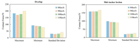
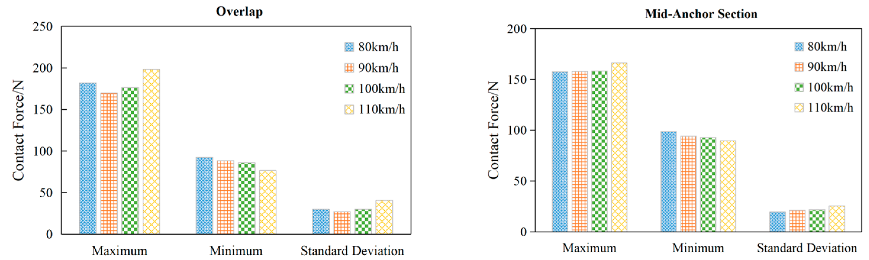
In Figure 2 and Table 3, as the operational speed increases, the maximum contact force generally exhibits an upward trend, while the minimum value decreases slightly, and the standard deviation of the contact force increases significantly. A comparison of the contact force data between the overlapping span and the mid-span is illustrated in Figure 3. The influence of operating speed on the pantograph-catenary contact force indicators at the overlap span and the mid-anchor section is shown in Table 4 and Table 5.
Figure 3.
Comparison of Contact Force Data between Overlaps and Mid-Anchor Sections.
Table 4.
Influence of operating speed on pantograph–catenary contact force indicators at the overlap span.
Table 5.
Influence of operating speed on pantograph–catenary contact force indicators in the mid-anchor section.
As illustrated in Figure 3, the maximum value and standard deviation of the pantograph-catenary contact force at the overlapping span are higher than those at the mid-span at any given speed. Furthermore, the fluctuations in contact force at the overlapping span become more pronounced with increasing speed compared to the mid-span. As the speed escalates to 110 km/h, both the maximum contact force and its standard deviation exhibit a significant increase. It can be inferred that the contact force at the overlapping span demonstrates a higher sensitivity to train speed than at the mid-span, leading to a greater degree of abnormal wear at the overlapping span.
2.2.2. Contact Wire Stress and Disengagement
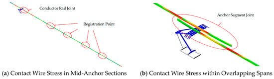
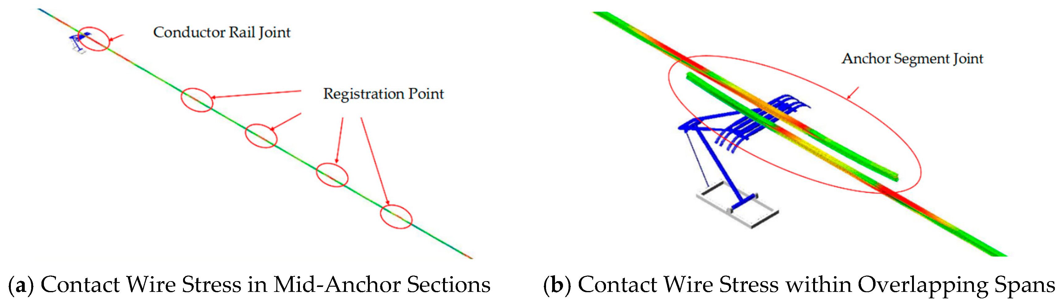
To analyze the stress variations under the action of moving loads, the stress changes in the catenary system during pantograph operation were calculated based on the simulation model established in the preceding section. The stress distribution across the entire catenary line is illustrated in Figure 4, where the color gradient of the contact wire, ranging from dark to light, represents the stress magnitude from high to low.
Figure 4.
Contact Wire Stress.
As observed in Figure 4a, the stress at the registration points is significantly higher than that on either side of these points, while the stress at the intermediate joints is noticeably greater than at the registration points. This is primarily attributed to the structural characteristics of the intermediate joints, which function as stress concentration points. Additionally, the relatively high contact force in these areas directly influences the stress magnitude. Figure 4b indicates that the stress at the overlapping spans is significantly higher than at other locations.
To further analyze the stress variations, this study conducted a statistical analysis of the top 3000 maximum stress values within an anchor section. The peak stress values predominantly occur at the registration points, implying that the maximum stress undergoes periodic variations corresponding to the span length. Consequently, areas of severe wear are more likely to appear at registration points, where the conductor rail is more prone to irreversible plastic deformation, thereby increasing the susceptibility to disengagement.
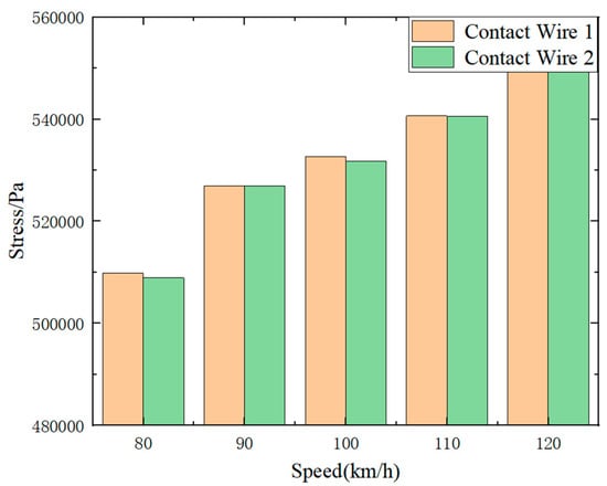
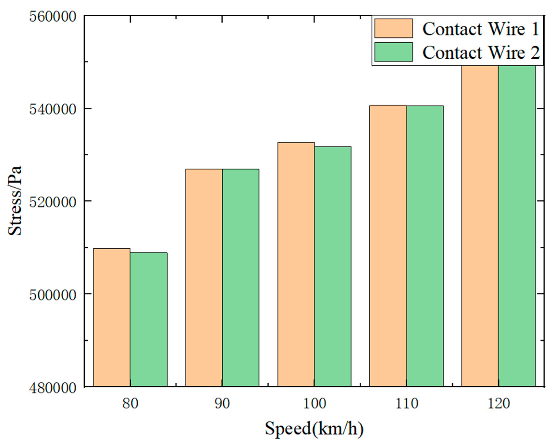
To further examine the influence of various parameter changes on stress, the stress variations relative to operational speed were statistically analyzed, with the maximum stress of each anchor section serving as the primary analytical target. The specific results are presented in Figure 5.
Figure 5.
Peak Stress under Varying Speeds.
As illustrated in Figure 5 and Table 6, the maximum stress on the contact wire increases as the operational speed escalates. This indicates that higher speeds lead to a greater susceptibility to abnormal wear and contact wire disengagement. The underlying mechanism is that elevated speeds result in higher peak contact forces, which in turn increase the surface pressure and consequently the stress during the pantograph-catenary interaction. As a result, the conductor rail jaw becomes more prone to plastic deformation, significantly increasing the likelihood of contact wire disengagement.
Table 6.
Influence of operating speed on the maximum stress value.
2.3. Analysis of Field-Observed Environmental Degradation Factors
It should be noted that the temperature, humidity, and electrochemical corrosion factors discussed in this section are mainly used to explain possible degradation mechanisms of the clamping performance of the conductor rail jaw under long-term service conditions. These factors were not directly incorporated as coupled parameters in the pantograph–catenary dynamic simulation model. The quantitative simulation in this study mainly focuses on contact force fluctuation, contact wire stress concentration, and the influence of disengagement degree on pantograph–catenary dynamic response.
2.3.1. Temperature Factors
Temperature fluctuations serve as a crucial physical factor that induces the displacement of the contact wire inside the conductor rail, ultimately leading to material fatigue and geometric relaxation. Due to the discrepancy in thermal expansion and contraction behaviors between metals, the conductor rail (typically composed of aluminum alloy) and the contact wire (copper) possess different coefficients of linear thermal expansion. Under the influence of ambient temperature differences or Joule heating generated by heavy currents, inconsistent axial expansion and contraction occur between the two components, driving the contact wire to experience longitudinal contraction or expansion within the slot. Prolonged exposure to high-temperature environments or frequent thermal cycling induces minor variations in the elastic modulus of the aluminum alloy conductor rail. These periodic thermal stress fluctuations consequently lead to the gradual relaxation of the initial clamping force at the conductor rail jaw. Simultaneously, elevated temperatures cause a subtle shift in the overall stiffness of the rigid suspension system and increase the mid-span uplift, thereby altering the distribution of the pantograph-catenary dynamic contact force and contact wire stress, which indirectly escalates the risk of disengagement.
2.3.2. Humidity Factors
In recent years, with the continuous rebound of the groundwater table in Beijing, structural water leakage in subways has become increasingly severe. Currently, multiple sections across several lines within the Beijing subway network are located below the groundwater table, with the total length reaching over 300 km, which accounts for nearly half of the entire network. The tunnel water leakage in a typical section of a certain Beijing subway line is illustrated in Figure 6.
Figure 6.
Tunnel Water Leakage on a Specific Line of the Beijing Subway.
The tunnel leakage water contains corrosive substances from the geological strata, directly inflicting corrosion damage on the structural components of the overhead contact system. The typical corrosion of the conductor rail in the Beijing subway network is illustrated in Figure 7.
Figure 7.
Chemical Corrosion of the Conductor Rail.
Media intrusion and interface degradation: The high humidity of the tunnel environment acts as an inducer of electrochemical reactions and a catalyst for the degradation of mechanical properties. Humid air within the tunnel or water seepage from the ceiling easily accumulates at the conductor rail slot, forming a thin electrolytic water film. Furthermore, the interior of the conductor rail is typically coated with conductive or anti-corrosion grease; continuous high humidity or water vapor flushing can lead to the emulsification and loss of these grease components, directly exposing the metal interface and causing abnormal variations in the friction coefficient. The combined effect of humidity and the clamping stress of the conductor rail itself accelerates the microcrack propagation in the metallic material, making the conductor rail more susceptible to plastic deformation when subjected to pantograph impacts.
2.3.3. Chemical Factors
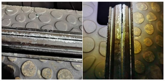
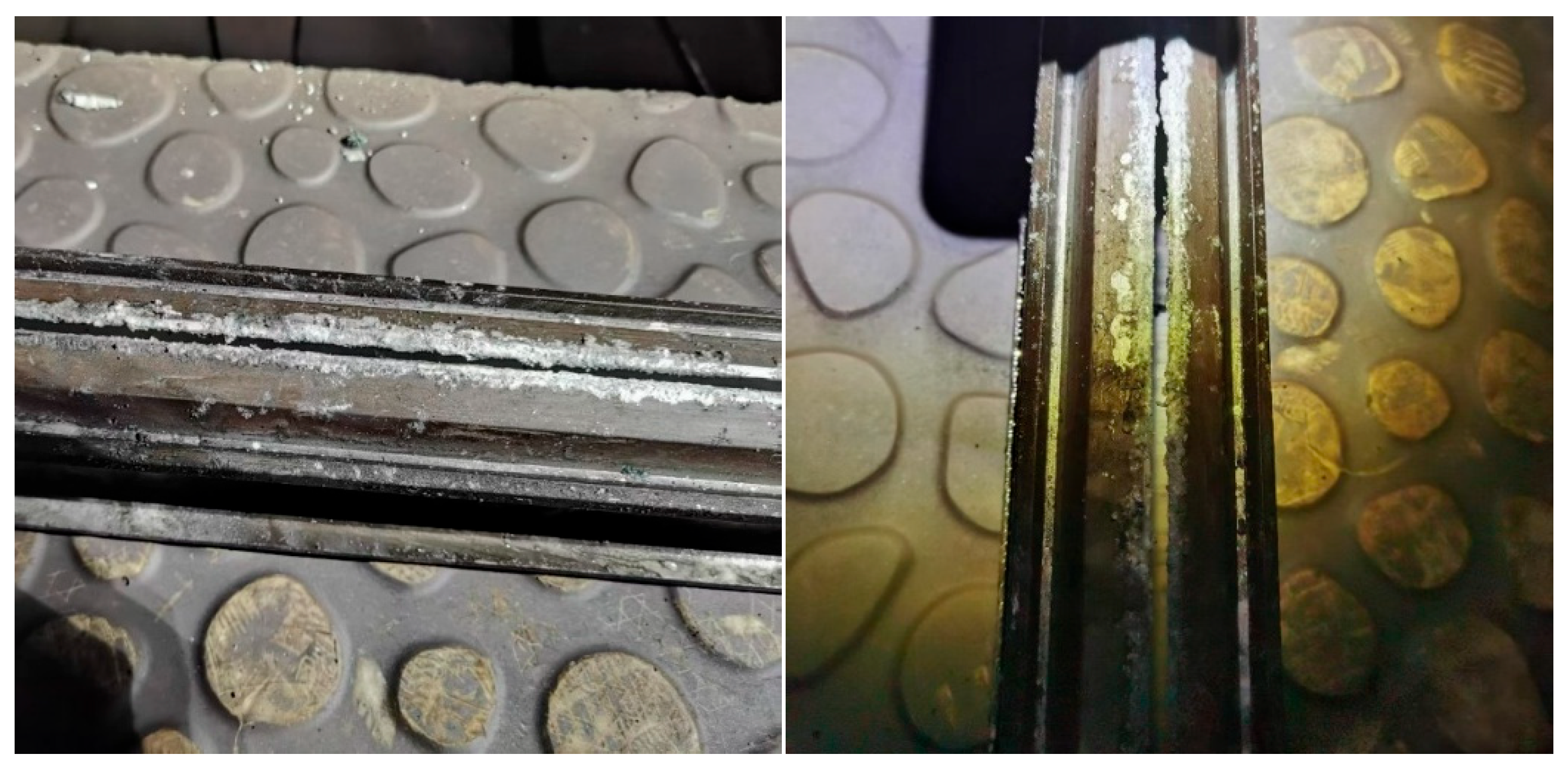
Electrochemical expansion is another critical mechanism leading to contact wire disengagement. Aluminum-copper galvanic reaction: In the presence of moisture at the contact interface, aluminum (the conductor rail), which possesses a lower electrochemical potential, acts as the anode and undergoes an oxidation reaction, while copper (the contact wire), with a higher potential, serves as the cathode. The fundamental reactions are as follows:
The first reaction represents the anodic dissolution of aluminum, in which the aluminum conductor rail loses electrons and forms aluminum ions. The second reaction represents the cathodic oxygen reduction process in a humid and oxygen-containing tunnel environment, where dissolved oxygen consumes the electrons released from the aluminum side and generates hydroxide ions. Subsequently, aluminum ions combine with hydroxide ions to form aluminum hydroxide precipitates. The final reaction summarizes the overall corrosion process of aluminum under humid and aerated conditions.
These reactions may occur when tunnel leakage water or condensed moisture forms a thin electrolyte film between the aluminum conductor rail and the copper contact wire. The generated hydrated aluminum corrosion products can gradually accumulate in the narrow conductor rail jaw and produce a local wedging effect. As a result, the jaw clearance increases, the clamping capacity decreases, and the contact wire becomes more susceptible to disengagement under pantograph-induced dynamic excitation.
The volume of the reaction-generated white corrosion products, such as aluminum hydroxide, is typically several times that of the consumed base metal. The continuous accumulation of these products within the enclosed slot generates a substantial internal expansion pressure. This pressure persistently forces the conductor rail jaw outward, leading to a progressive enlargement of the jaw clearance. When this clearance exceeds the critical clamping threshold of the contact wire shoulder, the contact wire loses its physical constraint and eventually detaches under the dynamic vibrations induced by passing trains. The morphology of the white corrosion products and the associated corrosion phenomenon are illustrated in Figure 8.
Figure 8.
Electrochemical Expansion of the Conductor Rail.
3. Finite Element Simulation-Based Hazard Analysis of Rigid Overhead Contact System Disengagement
3.1. Effects of Disengagement Degree on the Associated Hazards
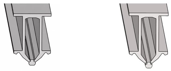
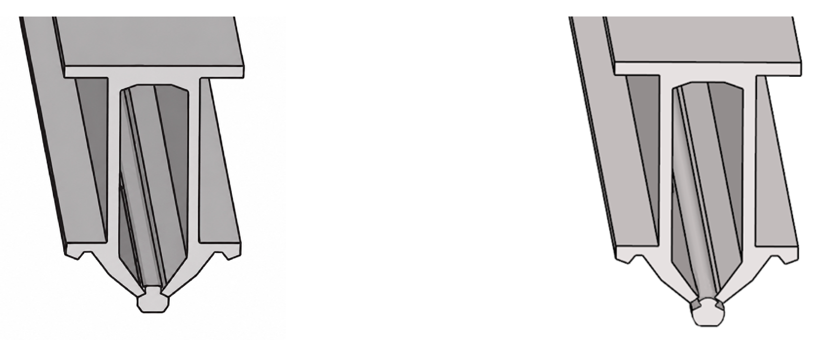
The disengagement scenario was simulated at the overlapping span, and the specific model comparison is illustrated in Figure 9.
Figure 9.
Comparison before and after disengagement.
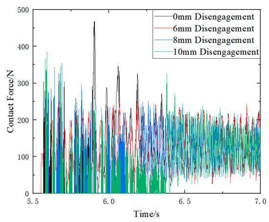
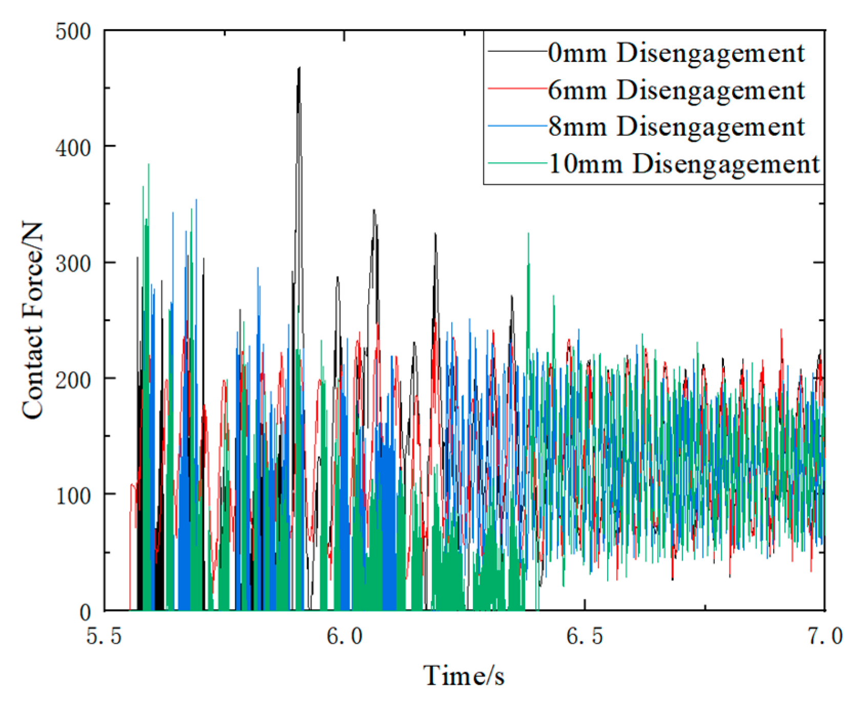
In the simulation, the contact wire was divided into two segments: the first anchor section preceding the disengagement location, and the second anchor section originating from the disengagement point. Because no disengagement occurred in the first anchor section, the experimental groups yielded identical pantograph-catenary contact force results to the control group. Conversely, disengagement was initiated at the beginning of the second anchor section, causing the simulation results of the experimental groups to exhibit significant discrepancies depending on the disengagement severity. Figure 10 and Table 7 illustrates the comparative simulation results of the pantograph-catenary contact force when the train passes through the overlapping span under five disengagement conditions: 0, 0.6, 0.8, and 1 cm. At the overlap span, as the contact wire disengagement amplitude gradually increases, the contact loss rate at the disengagement position increases from 0% at 0 mm to 36.03% at 10 mm. When the disengagement amplitude reaches 6 mm, both the maximum contact force and the standard deviation show relatively large values. Overall, the standard deviation of the contact force and the contact loss rate generally increase with the aggravation of contact wire disengagement.
Figure 10.
Effects of Contact Wire Disengagement Degree on Pantograph-Catenary Contact Force.
Table 7.
Influence of disengagement amplitude on pantograph–catenary contact force.
3.2. Effects of Disengagement Location on the Associated Hazards
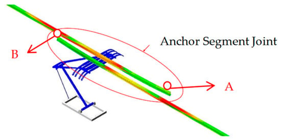
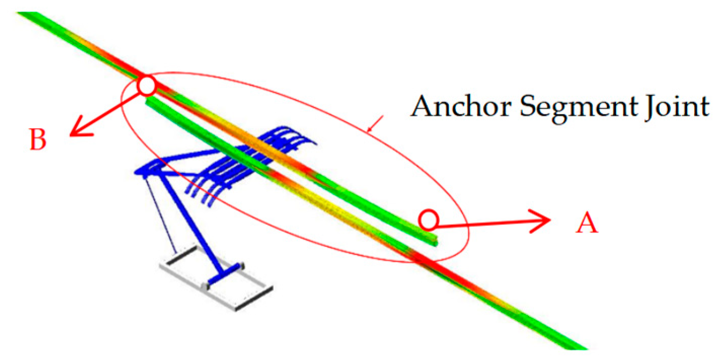
Contact wire disengagement can be classified into disengagement in the same direction as train operation and that in the opposite direction, as exemplified by the disengagement at points A and B in Figure 11.
Figure 11.
Position of Disengagement.
The hazards associated with disengagement vary between the two scenarios. Based on a comparative analysis of these distinct conditions, the following conclusions can be drawn:
The hazard of disengagement at location B is significantly greater than that at location A. Specifically, disengagement at location B is highly prone to inducing extreme pantograph-catenary contact forces, which can easily cause severe wear on the carbon sliders. In contrast, the disengagement scenario at location A increases the standard deviation of the contact force and marginally elevates its peak value, inducing a period of oscillation after the pantograph passes the disengagement point. Nonetheless, both the contact loss rate and the contact loss range for location A remain smaller than those observed in the disengagement scenario at location B.
4. Engineering Detection Route for Contact Wire Disengagement
4.1. Continuous 3D Profile Scanning Technology for Conductor Rails
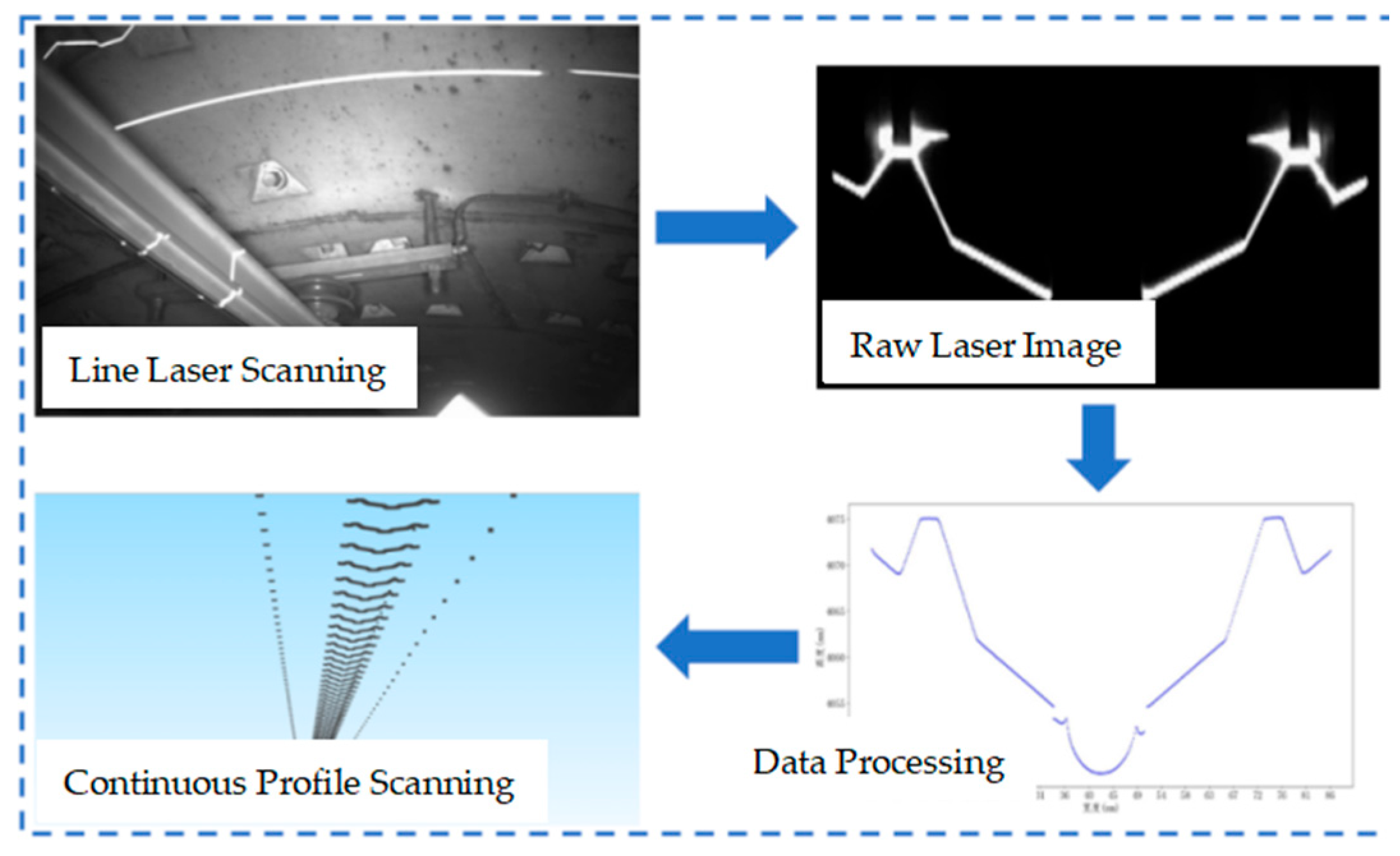
A dedicated research and development (R&D) initiative was carried out to develop a 3D line-laser profiling function for contact wires, leveraging the Type 3B comprehensive inspection train. This function enables the automated detection of contact wire scoring, wear, and disengagement based on the captured geometric profiles. The profile resolution of the contact wire reaches 0.1 mm; the laboratory static detection accuracy for contact wire wear can reach 0.2 mm, while the field measurement accuracy is superior to 0.5 mm.
4.1.1. Catenary Profile Scanning
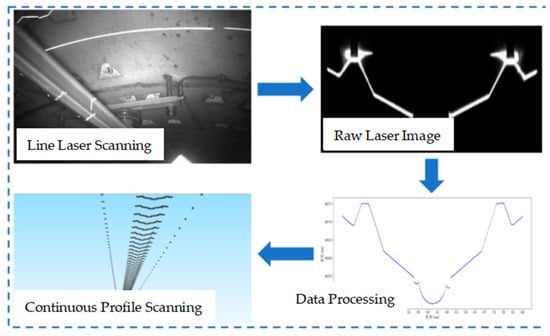
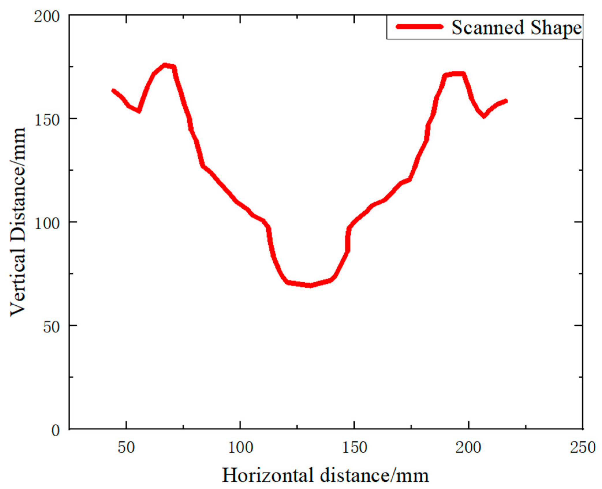
The catenary profile of a specific operational line was comprehensively scanned, and the scanning process is shown in Figure 12. By identifying the clearance between the conductor rail and the contact wire, the detection of severe contact wire disengagement was successfully achieved, followed by further fine-tuning and optimization based on the field measurement results.
Figure 12.
Catenary Profile Scanning Results on a Specific Metro Line.
Continuous 3D profile scanning for conductor rails is capable of acquiring 400 profiles per second, providing high detection accuracy. However, the resulting massive volume of data introduces challenges such as prolonged processing times. Consequently, if this technology is solely deployed to detect catenary disengagement across an entire operational line, it will incur substantial computational overhead and time consumption.
4.1.2. Profile-Based Contact Wire Disengagement Identification
The profile-based identification principle for contact wire disengagement is illustrated in Figure 13. Whether disengagement occurs is determined by evaluating the distance between the bottom-most point of the contact wire and the conductor rail slot. While this method is capable of identifying severe disengagement involving a substantial displacement magnitude, it encounters significant difficulties in detecting minor disengagement characterized by small displacements. Specifically, disengagement increases this reference distance, whereas material wear reduces it. On a specific Beijing subway line, the typical disengagement amount ranges from 1 to 2 mm, which is remarkably close to the magnitude of contact wire wear. Such minor disengagement of 1–2 mm usually corresponds to an early-stage defect, and its influence on pantograph–catenary contact force may not be obvious. Therefore, it is difficult to identify such defects only through contact force variation, which further demonstrates the necessity of image- and profile-based inspection for early detection. Consequently, obscured by the confounding effects of wire wear, minor disengagement becomes exceptionally challenging to isolate and identify. Furthermore, other operational defects such as contact wire scoring and eccentric wear can be effectively identified using the continuous 3D profile scanning technology.
Figure 13.
Profile-Based Principle for Identifying Contact Wire Disengagement.
4.2. High-Definition Continuous Imaging Technology for Conductor Rails
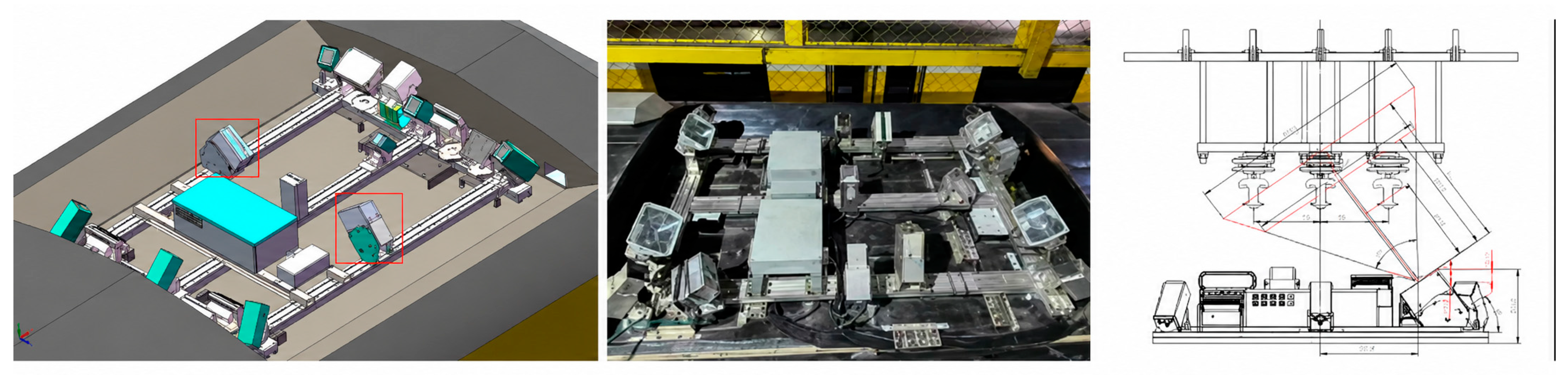
To meet the requirements for continuous conductor rail imaging, a retrofit was performed on the Type 3B comprehensive inspection train to transition the original registration-point-triggered shooting scheme into a continuous capture scheme. This upgrade allows for the preservation of complete, full-line high-definition images of the catenary system, establishing a solid foundation for identifying structural defects such as contact wire disengagement and conductor rail corrosion. The preliminary scheme for the camera retrofit is illustrated in Figure 14.
Figure 14.
Camera Modification for Continuous Conductor Rail Imaging.
4.2.1. Continuous Shooting with Area-Scan Cameras
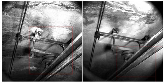
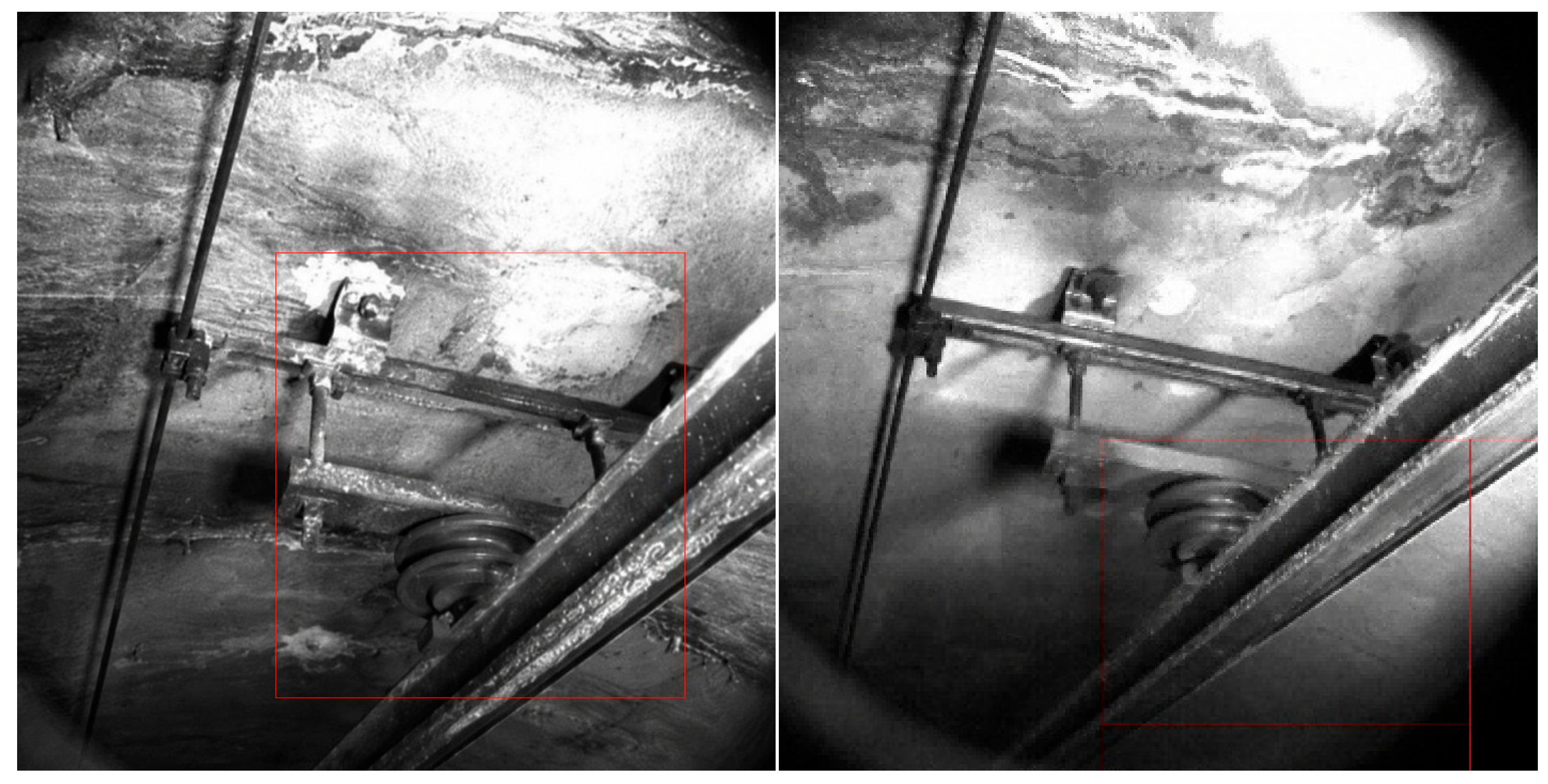
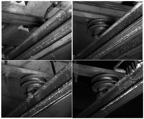
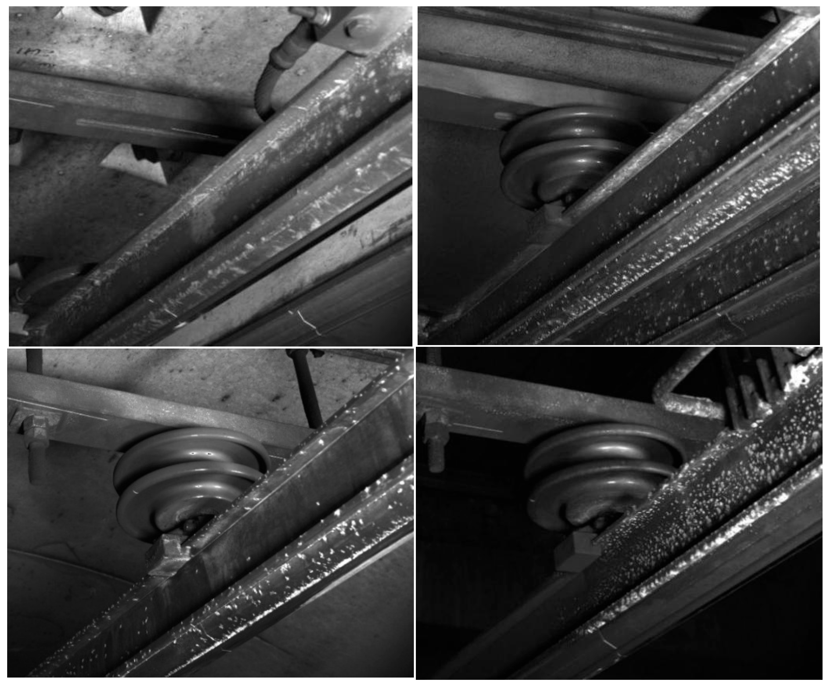
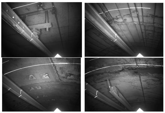
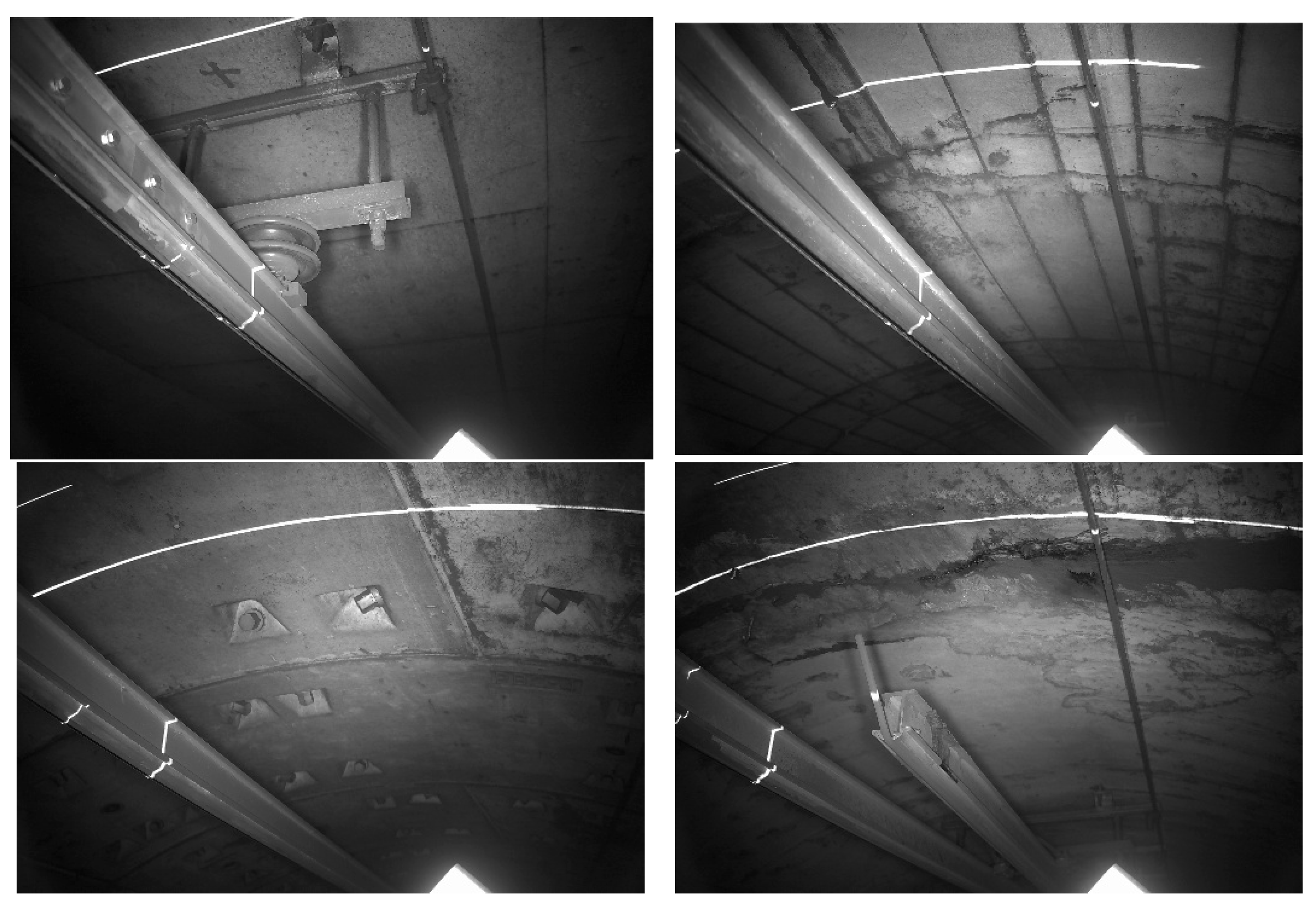
The image captured by the area-scan camera is shown in Figure 15. Due to the single-camera configuration, the imaging quality degrades significantly when the conductor rail is either too close or too far, making it difficult to discern conductor rail disengagement.
Figure 15.
Image Captured by the Area-Scan Camera.
4.2.2. Continuous Shooting with Line-Scan Cameras
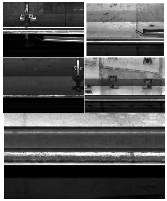
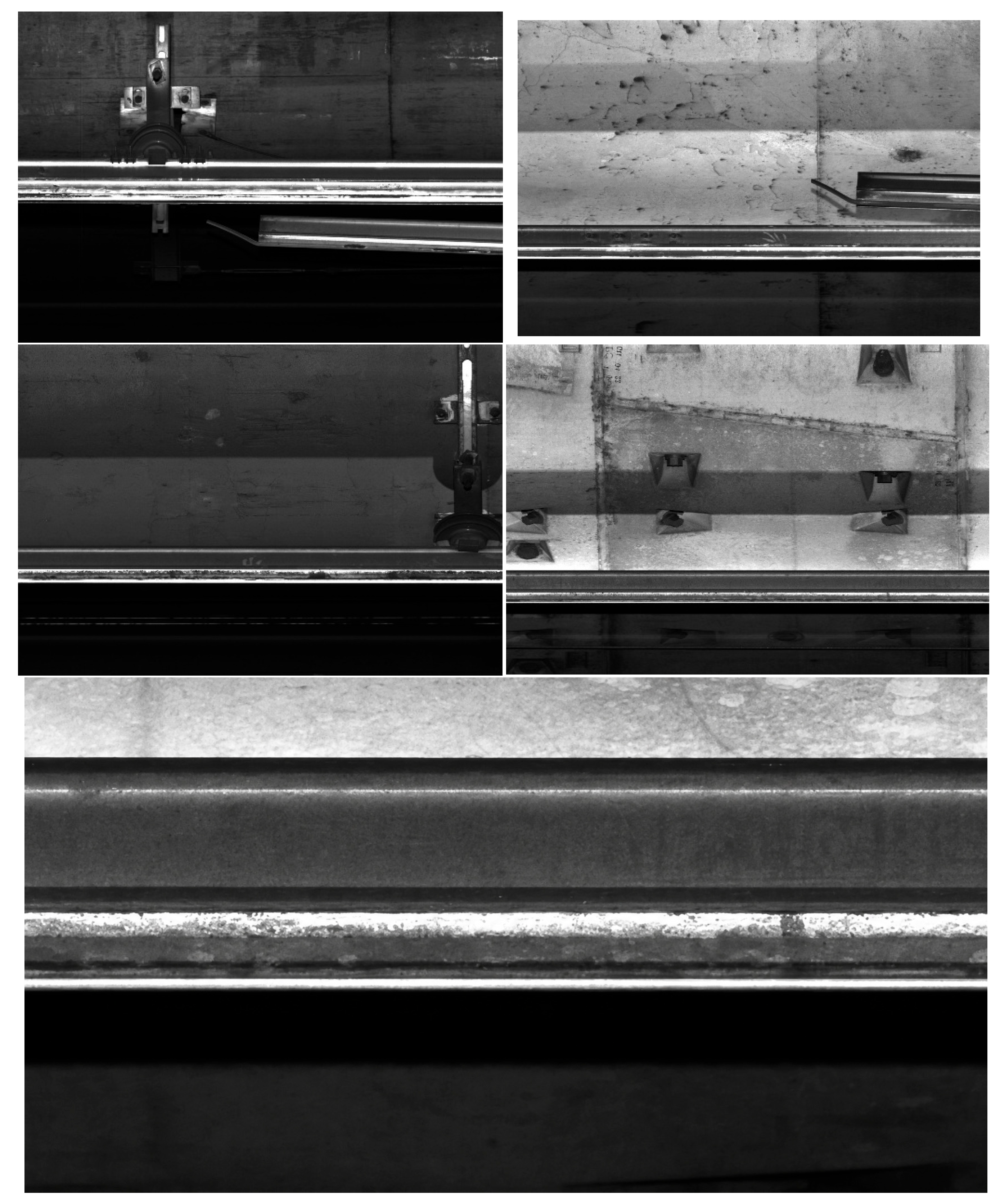
Scanning via dual line-scan cameras yields a conductor rail image with a horizontal resolution of 2048 pixels, as illustrated in Figure 16. The shooting angle of the line-scan cameras can be properly configured for capturing the conductor rail, thereby delivering a relatively high image quality.
Figure 16.
Image Captured by the Line-Scan Camera.
However, the contact wire is typically coated with conductive grease, causing its lateral sides to appear black. Additionally, oxidation layers induced by phenomena such as electric arcing tend to accumulate within the conductor rail slot. Consequently, distinguishing among the grease, the oxidation layer, and the actual disengagement gap based solely on image features poses a certain challenge.
4.3. Engineering Inspection Procedure for Contact Wire Disengagement
For field inspection and maintenance decision-making, a preliminary classification criterion is proposed according to the disengagement amplitude. It should be noted that, from the viewpoint of structural safety of rigid overhead contact systems, the contact wire should be firmly clamped inside the conductor rail jaw. Therefore, any confirmed disengagement should be regarded as a defect. In field maintenance, the severity can be classified according to the disengagement amplitude. When the disengagement amplitude is not greater than 1 mm, it can be regarded as being within the range of normal fluctuation or measurement uncertainty and should be continuously tracked. When the disengagement amplitude is between 1 mm and 3 mm, it can be classified as minor or early-stage disengagement and should be included in the warning list for repeated inspection. When the disengagement amplitude exceeds 3 mm, it can be classified as an obvious disengagement defect and maintenance should be scheduled. When the disengagement amplitude reaches 6 mm or above, the pantograph–catenary dynamic response deteriorates significantly, and the defect should be regarded as a severe disengagement risk requiring priority treatment. This classification criterion is mainly used for engineering inspection and maintenance decision-making and should be further refined with more field inspection data in future work.
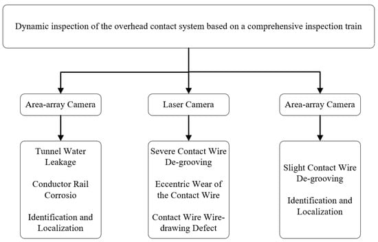
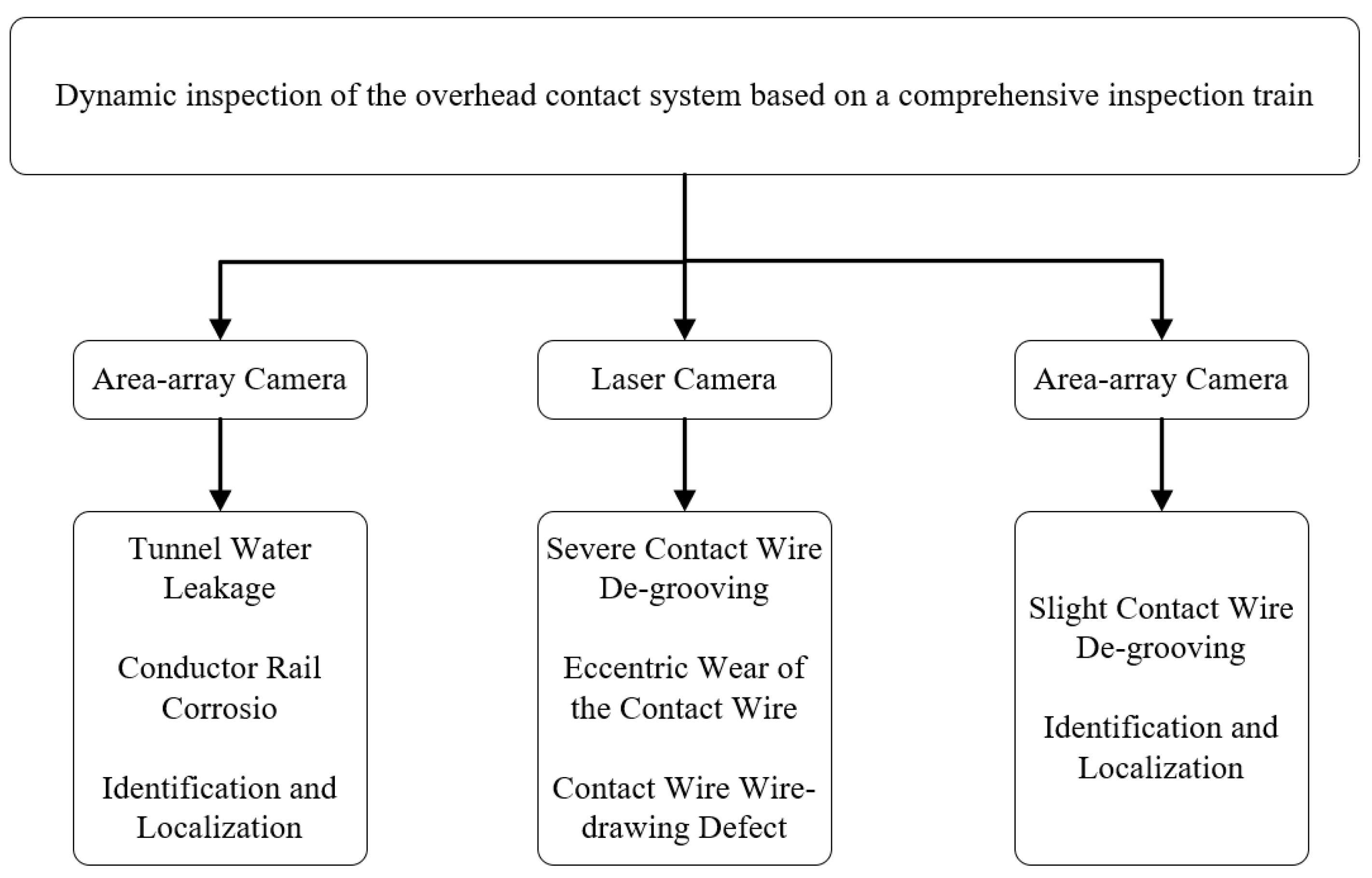
The technical roadmap for contact wire disengagement detection is illustrated in Figure 17. First, sections affected by severe tunnel water leakage and conductor rail corrosion are localized using images acquired by area-scan cameras. Subsequently, the contact wire profiles within these identified sections are analyzed with particular emphasis on specifically identifying severe contact wire disengagement defects (>3 mm). Finally, in conjunction with line-scan camera images, minor contact wire disengagement defects (≤3 mm) are identified.
Figure 17.
Technical Roadmap for Contact Wire Disengagement Detection.
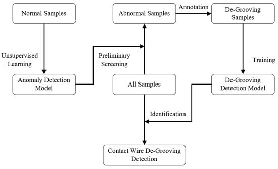
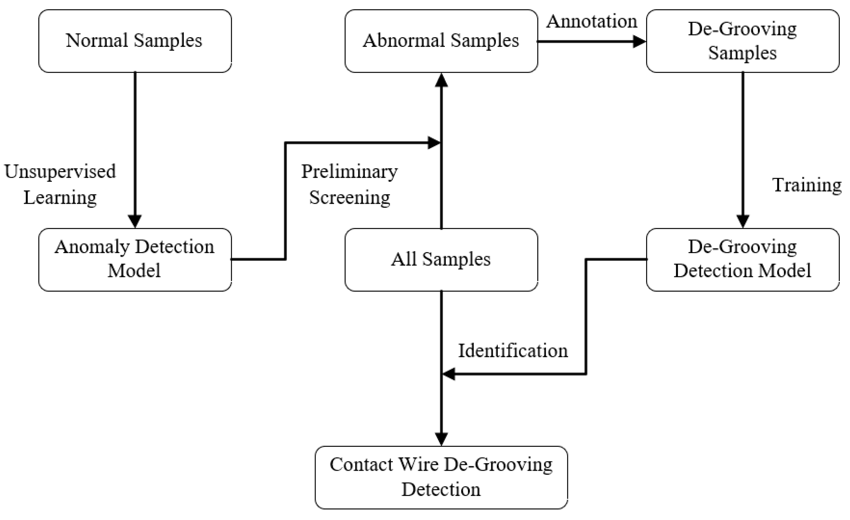
The procedure for identifying minor contact wire disengagement using line-scan cameras is illustrated in Figure 18. For minor disengagement defects, line-scan camera images can be used to assist the screening of the conductor rail jaw region. However, conductive grease, oxidation layers, contact wire wear, and illumination conditions may interfere with the image features, making the automatic identification of minor disengagement defects challenging. Therefore, at the present stage, line-scan images are mainly used for the auxiliary judgment of suspected disengagement sections, which should be further confirmed by manual verification and field inspection results. In future work, an intelligent recognition algorithm can be further trained and quantitatively validated based on the accumulation of a large number of field samples and manual annotations.
Figure 18.
Identification Steps for Minor Contact Wire Disengagement.
On certain operational lines, the disengagement can be subtle, manifesting as a gap of only 1–2 mm. Due to confounding interferences such as conductive grease and oxidation layers, the image-based identification of these minute disengagement gaps poses significant difficulties. Consequently, false positives are inevitable during the initial phase of deployment. Continuous optimization of the identification capability and accuracy will necessitate the accumulation of a substantial volume of field samples through extended engineering applications.
5. Conclusions
Contact wire disengagement in rigid overhead contact systems (OCS) can induce critical issues such as pantograph-catenary arcing, pantograph striking, and severe abnormal wear. To proactively prevent disengagement, a solid-model finite element method (FEM) simulation was first employed to investigate the underlying mechanisms of disengagement generation, followed by a simulation of disengagement scenarios to evaluate the associated hazards, yielding the following conclusions:
During train operation, the standard deviation of the contact force when passing through overlaps is significantly larger than that in other sections. The peak stress of the contact wire primarily occurs at the registration points and increases with train speed. In summary, pantograph–catenary contact force fluctuation and contact wire stress concentration are important mechanical factors inducing contact wire disengagement. Environmental factors such as temperature variation, humidity, and electrochemical corrosion may weaken the clamping performance of the conductor rail jaw during long-term service and thereby increase the risk of disengagement. However, their quantitative influence still requires further experimental investigation and field-data validation. Specifically, disengagement at the overlaps further exacerbates the standard deviation of the contact force, elevates the peak contact force, and accelerates the wear of the carbon sliders.
Based on the above mechanical analysis, an engineering detection route integrating area-scan imaging, three-dimensional profile scanning, and line-scan imaging was further proposed. This route can provide a technical reference for locating severe disengagement defects and assisting the inspection of minor disengagement defects in field applications.
Author Contributions
Conceptualization, C.L. and C.Y.; methodology, C.L.; software, C.L.; validation, Z.G., Z.W. and Q.W.; formal analysis, W.L.; investigation, C.L.; resources, C.L.; data curation, C.Y.; writing—original draft preparation, Z.G.; writing—review and editing, W.L.; visualization, Q.W.; supervision, Z.W.; project administration, W.L.; funding acquisition, Z.G. All authors have read and agreed to the published version of the manuscript.
Funding
This research received no external funding or This research was funded by [Scientific Research and Development Fund Project of China Academy of Railway Sciences Corporation Limited] grant number [2024YJ359].
Data Availability Statement
The authors declare no conflict of interest.
Conflicts of Interest
Author Zhaofeng Gong were employed by the company Power Supply Branch of Beijing Metro Operation Co., Ltd., Beijing 100044, China. Authors Zhiheng Wei and Qihao Wang were employed by the company Urban Rail Transit Center, China Academy of Railway Sciences Co., Ltd., Beijing 100081, China. The remaining authors declare that the research was conducted in the absence of any commercial or financial relationships that could be construed as a potential conflict of interest.
References
- Lu, J. Study on Dynamic Simulation and Characteristics Analysis of Catenary Failures. Doctoral Dissertation, Southwest Jiaotong University, Chengdu, China, 2018. [Google Scholar]
- Lu, J. Study on the Failure of Rigid Catenary Based on the Virtual Prototyping Technology. Railw. Locomot. Car 2018, 38, 66–72. [Google Scholar] [CrossRef]
- Gao, H. Research on Analysis and Solutions for Contact Wire Disengagement in Rigid Catenary Systems. Technol. Wind. 2018, 180. [Google Scholar] [CrossRef]
- Li, Q.X. Analysis and Solution of Contact Wire Disengagement of Rigid Overhead Catenary System. Sci. Technol. Vis. 2017, 217. [Google Scholar] [CrossRef]
- Guan, J.F.; Ouyang, H.X. Review and Prospect of Studies on Rigid Overhead Catenary. Urban Rapid Rail Transit. 2016, 29, 37–43+59. [Google Scholar]
- Guan, J.F.; Wu, J.H.; Dong, L.M. Dynamic coupling equations between pantograph and overhead rigidconductor rail by using numerical method. J. Railw. Sci. Eng. 2016, 13, 362–368. [Google Scholar] [CrossRef]
- Tian, S.P. Research on Key Technology of Overhead Rigid Contact System in Active Fault of Urumqi Subway. Railw. Stand. Des. 2017, 61, 141–145. [Google Scholar] [CrossRef]
- Yang, Z.F.; Huang, Z.W.; Pan, L.; Huang, C.; Xing, T.; Fu, R.; Zhang, H.; Wei, W.; Wu, G. Analysis and Prediction of Uneven Wear in Metro Pantograph-Rigid Catenary System. Tribol. Int. 2024, 198, 109925. [Google Scholar] [CrossRef] [Scilit]
- Ren, W.J.; Chen, G.X. Experimental Study on the Wear Mechanism of the Contact Line in Rigid Pantograph-Catenary Systems. Tribol. Int. 2023, 187, 108739. [Google Scholar] [CrossRef] [Scilit]
- Yan, H.; Huang, P.P.; Cheng, C. Influence of Arc Discharge on the Temperature and Wear Behaviors of the Contact Strip in Pantograph-Rigid Catenary Systems Under AC Conditions. Wear 2024, 546, 205368. [Google Scholar] [CrossRef] [Scilit]
- Bucca, G.; Collina, A. A Procedure for the Wear Prediction of Collector Strip and Contact Wire in Pantograph–Catenary System. Wear 2009, 266, 46–59. [Google Scholar] [CrossRef] [Scilit]
- Benet, J.; Cuartero, F.; Rojo, T.; Tendero, P.; Arias, E. A Dynamic Model for the Study and Simulation of the Pantograph–Rigid Catenary Interaction with an Overlapping Span. Appl. Sci. 2021, 11, 7445. [Google Scholar] [CrossRef] [Scilit]
- Zhi, X.S.; Zhou, N.; Wei, H.F. A Coupled Approach and Analysis to Pantograph-Rigid Catenary System Considering the Contact Pair Wear and System Dynamic Interaction. Mech. Syst. Signal Process. 2025, 239, 113281. [Google Scholar] [CrossRef] [Scilit]
- Feng, X.H.; Gao, S.B. Static and Dynamic Analysis of Conductor Rail with Large Cross-Sectional Moment of Inertia in Rigid Catenary Systems. Energies 2023, 16, 1810. [Google Scholar] [CrossRef] [Scilit]
- Mei, G.M.; Zhang, W.H. Study on Dynamics of Rigid Suspension Catenary. J. China Railw. Soc. 2003, 25, 24–29. [Google Scholar] [CrossRef]
- Zhu, Z.Z. Study on Contact Force Simulation of Rigid Suspension Pantograph-Catenary System Based on Finite Element. Graduation Thesis, Southwest Jiaotong University, Chengdu, China, 2014. [Google Scholar]
- Tian, K. Study on Establishment and Simulation of Metro Pantograph and Rigid Catenary System. Graduation Thesis, Southwest Jiaotong University, Chengdu, China, 2018. [Google Scholar]
- Yu, J.X.; Yu, L.; Feng, C. Study of the Impact of the Inter Locking Joint on the Contact Pressure of Pantograph-Catenary System Based on Simulation Method. Electr. Eng. 2018, 150–153+156. [Google Scholar]

Disclaimer/Publisher’s Note: The statements, opinions and data contained in all publications are solely those of the individual author(s) and contributor(s) and not of MDPI and/or the editor(s). MDPI and/or the editor(s) disclaim responsibility for any injury to people or property resulting from any ideas, methods, instructions or products referred to in the content. |
© 2026 by the authors. Licensee MDPI, Basel, Switzerland. This article is an open access article distributed under the terms and conditions of the Creative Commons Attribution (CC BY) license.