


Abstract
In high-speed machining, linear toolpaths constructed from a series of short line segments are widely used but inevitably introduce tangent and curvature discontinuities at segment junctions, which may cause feedrate fluctuation and contouring error. To address this problem, this study proposes a real-time corner smoothing and feedrate interpolation method based on dual cubic Bézier transition curves and an optimal error assignment model. The main contribution lies in coupling analytical corner rounding with error allocation: the approximation error and maximum curvature of the transition curves are obtained explicitly, while the allowable tolerance is optimally distributed between approximation error and chord error so that the overall trajectory error remains within the prescribed bound. A jerk-limited look-ahead interpolator is then developed through reverse scanning and forward interpolation to satisfy geometric constraints, drive constraints, and feedrate commands. Simulation results for a three-dimensional toolpath show that the approximation error, chord error, and total trajectory error are all constrained within the preset tolerance of 0.05 mm. In the mask-machining case, the proposed method reduces the machining time to 13.9 s, corresponding to reductions of approximately 70% and 25% compared with the method without look-ahead and the method with look-ahead only, respectively. These results indicate that the proposed framework can improve motion smoothness and machining efficiency while maintaining trajectory accuracy.
1. Introduction
In high-speed machining (HSM), toolpaths produced by computer-aided manufacturing (CAM) systems are transformed into discrete “point-to-point” linear trajectories (G01 blocks consisting of short linear segments) to govern machine tool movements [1,2]. This discretization process inevitably introduces tangent and curvature discontinuities at the connections between adjacent segments [3]. Such discontinuities subsequently trigger feedrate fluctuations and contouring errors stemming from these fundamental limitations [4]. Given the continuous advancement of machining technologies in contemporary manufacturing, there is an imperative demand for high-precision interpolation capabilities in CNC systems that can smooth linear toolpaths featuring sharp corners, thereby fulfilling the stringent requirements of high-speed machining operations.
While look-ahead strategies have been integrated into CNC control systems to alleviate frequent acceleration and deceleration cycles of motion axes, the inherent discontinuities within linear segments persist in generating fluctuations in both feedrate and acceleration [5]. These instabilities exert detrimental effects on machining quality and operational efficiency. The application of smooth curves to mitigate sharp corners in linear toolpaths has been validated as an effective strategy for minimizing feedrate oscillations and reducing overall machining duration. Various approaches have been explored to enhance linear toolpath smoothness, including approximation-based smoothing techniques [6,7] and interpolation-based smoothing methods [8,9]. However, only a limited selection of commercial CAD/CAM software platforms, including UG and CATIA, support the generation of parametric-format NC codes, and such parametric codes remain compatible with only a restricted number of commercial CNC systems. As a consequence, the conversion of linear toolpaths into parametric curve representations has garnered considerable research interest.
Existing studies [10,11] indicate that substituting linear toolpaths with parametric curves represents a viable pathway for enhancing both machining efficiency and accuracy. Zhang et al. [12] developed a transitional approach for linear segments utilizing parametric cubic spline curves, establishing the spline curve through analysis of the transitional curve’s preconditions. Yau and Wang [13] introduced a Bézier interpolation technique aimed at mitigating discontinuities, defining a criterion to identify continuous short blocks (CSBs) and approximating these segments with cubic Bézier curves. Nonetheless, the tangent vectors at Bézier curve junctions exhibit discontinuity within the developed approximation algorithm. Linear toolpath interpolation employing B-spline or Non-Uniform Rational B-Spline (NURBS) methodologies has attracted extensive attention from researchers [14,15]. Sun et al. [16] introduced a real-time look-ahead interpolation framework based on dynamic B-spline transitions, where the transition curve is constrained to prevent intersection while maintaining high machining velocity. Tajima and Sencer [17] achieved continuous feedrate motion by directly planning jerk-limited velocity transitions for drives positioned near toolpath sharp corners. Contouring errors at corner locations were managed through the computation of cornering speed and transition duration. The same researchers [18] further developed a trajectory optimization algorithm designed to suppress inertial vibration excitation within machining equipment. Duan and Ji [19] proposed an adaptive NURBS interpolation technique incorporating real-time and flexible S-shaped curve acceleration/deceleration control. Nevertheless, the approximation error proves challenging to guarantee due to the absence of a clear relationship between the approximation error and the smoothed NURBS curve. Error estimation and iterative approximation procedures frequently demand substantial computational time.
Alternative smoothing approaches based on different curve types have also been explored. Tulsyan and Altintas [20] established an algorithm achieving C3 continuity at junctions while adhering to user-specified tolerance limits through parametric position micro-splines. Shi et al. [21] developed a five-axis machining corner smoothing method that rounds corners using pairs of quantic PH curves under constraints of tool tip contour and tool orientation tolerances. Huang et al. [22] presented a corner smoothing approach by constructing B-spline transition curves with seven control points.
From the above studies, it can be observed that B-spline/NURBS-based smoothing methods provide strong geometric representation capabilities, but their approximation error is often controlled through iterative fitting or local adjustment, which may increase computational burden in real-time CNC implementation. PH-curve and micro-spline methods can achieve high-order continuity, yet they usually require more complex curve construction or additional synchronization when tool orientation is involved. Existing look-ahead and S-curve feedrate planning methods improve the velocity profile, but they do not by themselves remove the geometric discontinuities of the original G01 blocks. Therefore, the unresolved issue is not merely to combine smoothing and look-ahead planning, but to establish a real-time scheme in which geometric smoothing, analytical curvature evaluation, and total trajectory-error control are explicitly coupled.
To address the aforementioned challenges, the present work focuses on a corner smoothing algorithm that differs from previous integration-type approaches in the following aspects:
(1) The approximation error and curvature extremum of the dual Bézier transition curves are obtained analytically;
(2) The approximation error and chord error are not treated as two isolated tolerances, but are allocated under a total trajectory-error constraint;
(3) The resulting toolpath achieves G2 continuity at the segment junctions;
(4) The smoothing module is integrated with a jerk-limited bidirectional look-ahead interpolator for online implementation.
This paper presents a real-time corner smoothing methodology founded on the above analytical rounding and optimal error assignment strategy. Compared with methods that only smooth the geometry or only optimize the feedrate profile, the proposed framework uses the analytical curvature and the allocated error bounds as shared constraints between the path-smoothing module and the feedrate interpolator. The remainder of this manuscript is structured as follows: Section 2 details the analytical corner rounding algorithm and the optimal error assignment algorithm. Section 3 describes the jerk-limited bidirectional scanning algorithm integrated within the real-time interpolator. Section 4 presents simulation and experimental results. Section 5 summarizes the contributions and limitations of this work.
2. The Online G2 Continuity Path-Smoothing Algorithm
2.1. Curvature-Continuous Bézier Transition Curves
Geometric continuity serves as a fundamental criterion for assessing the smoothness of piecewise curves at their junction points. Specifically, geometric continuity is employed to smooth piecewise linear toolpaths in this study. First-order geometric continuity, denoted as G1 continuity, requires the continuity of unit tangent vectors, whereas second-order geometric continuity, G2 continuity, ensures the continuity of curvature vectors at joint locations.
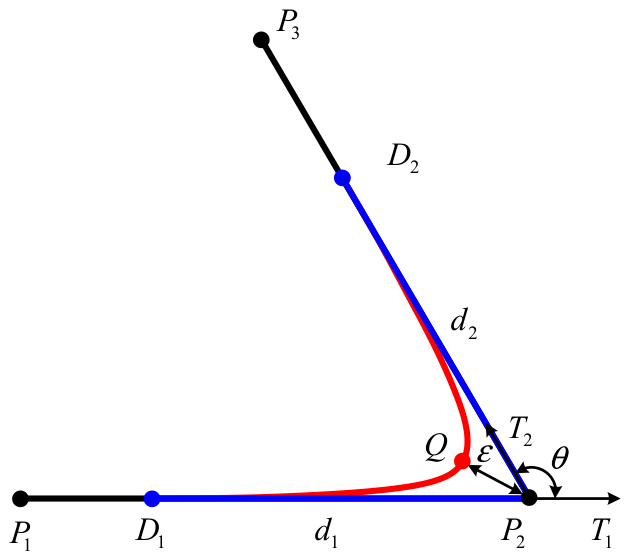
In this paper, a corner rounding strategy is proposed by using a pair of Bézier transition curves, as illustrated in Figure 1. The two adjacent line segments are represented by and . Their respective unit direction vectors are denoted as and , with the angle between them defined as . The two cubic Bézier transition curves, and , are determined by the control point sets and , respectively. The transition lengths and , correspond to the linear segment portions that are replaced by these smoothing curves. At the boundary points and , the unit tangent vectors are and , with both curvatures equal to zero. Moreover, at the connection points and , the unit tangent vectors and curvature values are mutually identical. Consequently, this smoothing approach successfully eliminates both tangency and curvature discontinuities at the corners.
Figure 1.
The definition of a pair of Bézier transition curves.
When the transition lengths are assumed to be equal (), the two cubic Bézier transition curves and are formulated as follows. The detailed mathematical derivation is provided in Appendix A.
where
where
The analytical expression for the corner approximation error is derived using Equation (5). Upon specifying a maximum allowable approximation error of , the transition length is constrained according to Equation (6). Furthermore, the peak curvature of the two transition Bézier curves—which plays a crucial role in velocity planning—is analytically determined via Equation (7). Comprehensive derivations for Equations (5)–(7) are presented in Appendix A.
2.2. Optimal Error Assignment Algorithm
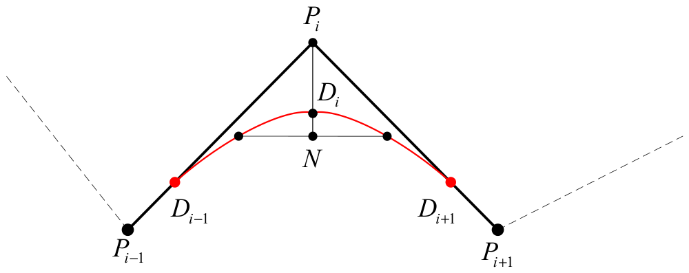
When path-smoothing and parametric interpolation are applied to linear toolpaths, approximation errors and chord errors may arise; their definitions and geometric relationship with the trajectory error are illustrated in Figure 2. These errors constitute the primary contributors to contour deviation. Notably, even when both approximation error and chord error are independently constrained within the specified tolerance limit, the maximum actual trajectory error can exceed the allowable tolerance because the two error components may accumulate in the same direction. To ensure precision while maximizing machining efficiency, an optimal error allocation scheme is derived to distribute the prescribed tolerance between approximation error and chord error.
Figure 2.
The definitions of approximation error and chord error.
Given that the approximation error is defined as , the chord error as , , and , respectively, the maximum trajectory error is required to remain within the allowable tolerance range.
The maximum transitional velocity is expressed as
where represents the interpolation period of the CNC system, and denotes the maximum acceleration capacity of the machine tool.
Based on Equations (6) and (7), lies on , while imposes constraints on the feedrate. Optimizing both and enables higher transition velocities to be achieved. If , . The optimal values of and can be derived as follows:
Based on the optimal error assignment model in Equation (10), the prescribed tolerance is divided into the maximum allowable approximation error and the maximum allowable chord error. The former is used in the path-smoothing process according to Equation (6), while the latter is used in the interpolation process according to Equation (12). In this way, the total trajectory error can be constrained by Equation (8).
2.3. Curvature-Continuous Blocks
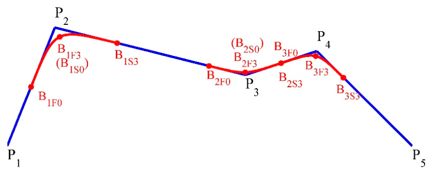
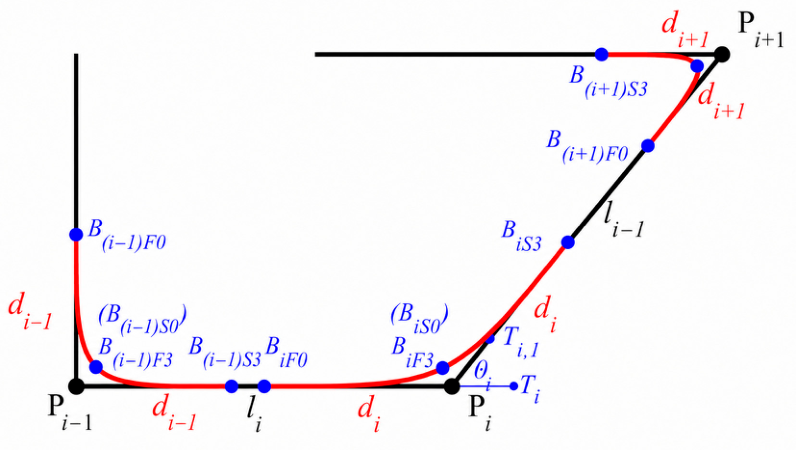
In order to describe the new curvature-continuous path, five types of blocks, Line-Bézier (LB), Bézier-Line-Bézier (BLB), Bézier-Bézier (BB), Bézier-Line (BL), and Line (L), are defined. As shown in Figure 3, four linear segments are taken as an example. A new path, which is composed of cubic Bézier curves (, , , , and ) and lines (, , and ) is then generated. The maximal curvatures occur at these points (, , and ). This means that the feedrate should reach a local minimum at these points. These points divide the smoothed path into several blocks. Line and Bézier curve form LB block. Bézier curve , line and Bézier curve form BLB block. Bézier curve and Bézier curve form BB block. Bézier curve and line form BL block. The junctions of these blocks are both tangent-continuous and curvature-continuous.
Figure 3.
Path-smoothing scheme for four consecutive linear segments.
The proposed methodology offers a significant advantage by effectively eliminating oscillations within the transition Bézier curve pairs and the remaining linear segments. Through the implementation of the oscillation avoidance algorithm, the curvature of the modified toolpath maintains continuity throughout the entire trajectory.
3. The Optimal Feedrate Interpolator with Look-Ahead Function
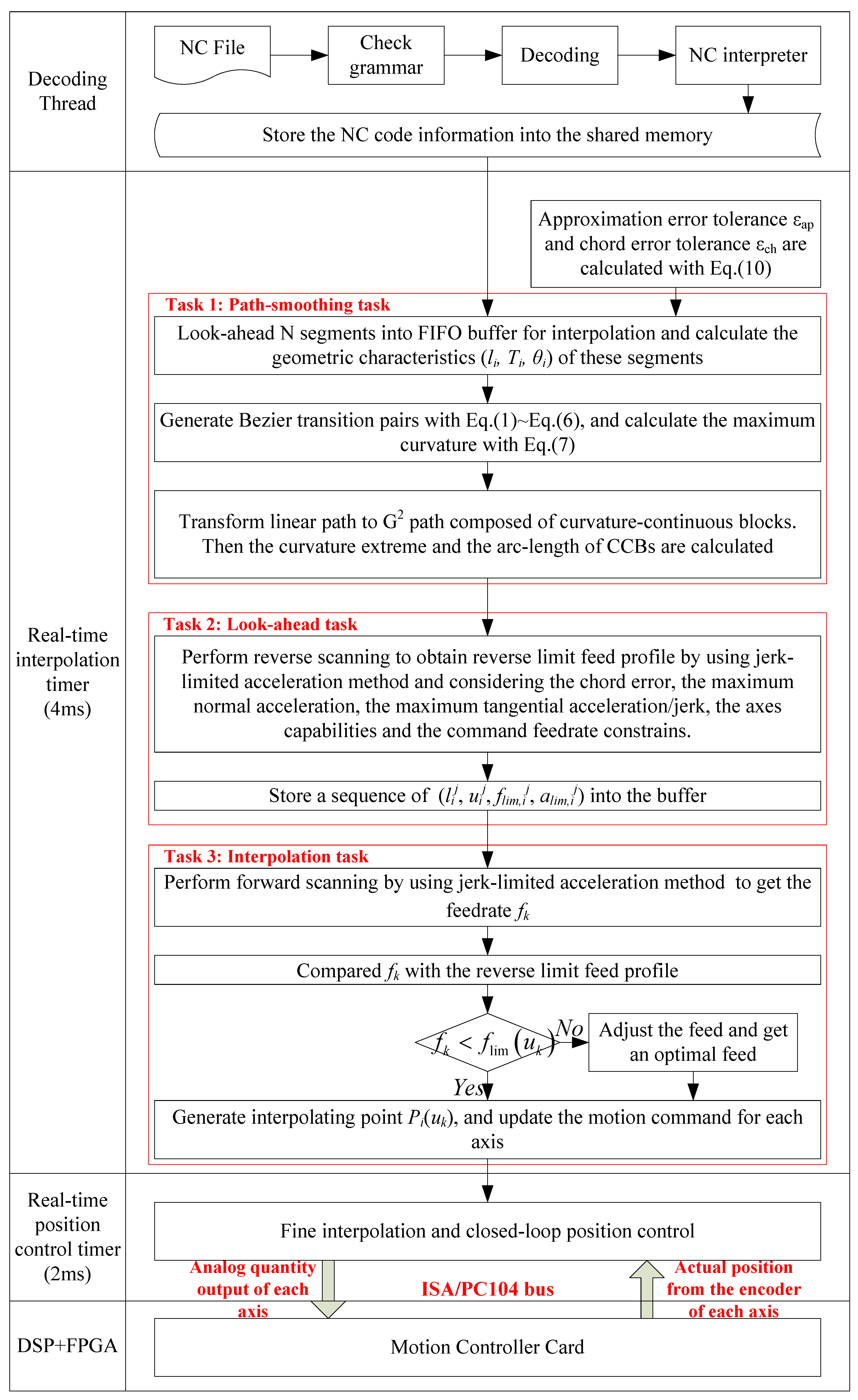
Based on the previously developed path-smoothing algorithm, a real-time optimal feedrate interpolator incorporating a look-ahead function is presented in this section. The interpolator comprises three principal components: the path-smoothing module, the look-ahead module, and the interpolation module.
3.1. Path-Smoothing Task
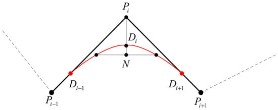
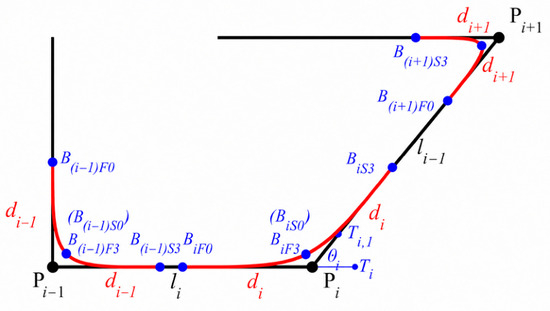
A look-ahead window is implemented in this work. This window encompasses a sequence of linear segments, with the count determined by the computational capability of the CPU. Upon initialization, N linear segments are loaded into the look-ahead FIFO (First-In First-Out) buffer from the shared decoding memory. These linear segments are represented by a point sequence {Pi = (xi, yi, zi), i = 0, 1, ⋯, N}, as illustrated in Figure 4. Then, the geometric characteristics (the lengths ; the unit direction vectors ; the vector angles ) of these linear segments are calculated simultaneously. The path-smoothing methodology described in Section 3 is executed within this window. Subsequently, the linear path is converted into a curvature-continuous trajectory consisting of Bézier transition pairs and linear segments. These Bézier curves and lines form curvature-continuous blocks (CCBs). For example, the ith linear segment is replaced by the ith CCB . The junction of ith CCB and (i + 1)th CCB is the maximum curvature point of the ith Bézier transition pair. The peak curvature and arc length of each newly generated CCB are computed and archived in the buffer, serving as essential inputs for feedrate planning within the look-ahead task. According to Equations (1)–(4), the ith CCB is expressed as .
Figure 4.
Transition Bézier curves to smooth the linear toolpath.
3.2. Look-Ahead Task
During this operation, a reverse scanning procedure is executed, proceeding from the terminal end of the look-ahead window to its initial point. To ensure the tool comes to a complete stop at the window’s endpoint, the terminal velocity is set to zero, and jerk-limited deceleration is applied from the endpoint back toward the start. Multiple constraints are considered, including chord error, maximum normal and tangential acceleration limits, machine axis capabilities, and the commanded feedrate. Two distinct velocity constraints are established:
First, at the peak curvature location of a Bézier transition pair, the minimum feedrate determined by both chord error and normal-acceleration constraints is termed the transitional velocity.
Second, the maximum feasible feedrate is defined by axis capabilities and the commanded feedrate. By intersecting these constraints, the feedrate limitation profile for forward scanning is obtained.
3.2.1. Maximal Transitional Velocity Constraint
When a cutting tool executes linear motion between consecutive interpolated points of a parametric curve, contour errors may arise. As curvature or feedrate increases, chord error correspondingly grows. The minimum radius of curvature is the reciprocal of the maximum curvature in the ith transition Bézier curve.
where represents the interpolation period of the CNC system and denotes the radius of curvature, . The minimum radius of curvature corresponds to the reciprocal of the maximum curvature in the ith transition of the Bézier curve, .
The feedrate is also limited by the maximum normal acceleration and of the machine tool.
Then the maximal transitional velocity at the end of the ith block is restricted by
The transitional feedrate is therefore obtained by combining the chord-error constraint in Equation (12), the normal-acceleration constraint in Equation (13), and the comprehensive limitation in Equation (14).
3.2.2. Maximum Feasible Feedrate Constraint
In high-speed machining operations, a predominant source of positioning error arises when input NC commands exceed the physical limitations of the axis servo systems. To mitigate such errors, machining dynamics are incorporated into the control framework, incorporating velocity and acceleration constraints established as upper bounds for each motion axis.
Arc length on the curve is denoted by , and the speed is parametrically determined by:
where denotes the first derivative of the curve with respect to parameter .
The velocity of the Λ-axis (Λ = X, Y, Z) can be expressed as
where denotes the feedrate of the tool tip point, and denotes the displacement of the Λ-axis. .
The velocity limit for axis Λ is designated as . Axis Λ’s velocity must be constrained by
Consequently, the tool tip feedrate is subject to
Furthermore, the acceleration of axis Λ along the curve can be derived by computing the time derivative of Equation (19).
where , and . These quantities are readily computable, as the first and second derivatives of the curve with respect to parameter can be obtained analytically.
When the Λ-axis acceleration limits are specified within the range from the lower bound to the upper bound, the feedrate and tangential acceleration must satisfy Equation (20). By combining Equations (18) and (20) with the programmed feedrate, the maximum feasible feedrate is obtained from Equation (21).
Considering the feedrate set by the programmer, , the optimized feedrate is determined by following equation:
3.2.3. Reverse Scanning
Upon completion of path smoothing, the original N linear segments are converted into N Curvature-Continuous Bézier (CCB) segments, comprising a combination of lines and Bézier curves. A backward scanning procedure commences from the Nth CCB and progresses toward the first. Multiple constraints are considered in this process, encompassing chord error, peak normal and tangential accelerations, jerk limits, machine axis capabilities, and the commanded feedrate.
During the scanning of the ith CCB, the accumulative arc length, the parameter, the feedrate limitation and the acceleration limitation of the jth sampling period are denoted as (lij, uij, flim,ij, alim,ij).
The specific implementation details of the reverse scanning procedure are outlined below:
Step 1: Let , , , , , , .
Step 2: If , proceed to Step 3; otherwise, proceed to Step 2a.
Step 2a: By employing jerk-limited S-shaped acceleration profiles while incorporating the maximum feasible acceleration constraint, the acceleration at the jth reverse feedrate point is computed as follows:
where the jerk limit Jm is established as a constant value within the CNC system’s control framework.
Step 2b: The jth reverse feedrate is subsequently determined by:
Step 2c: Parametric is approximated using first-order Taylor expansion.
Step 2d: The feedrate constraint , restricted by the chord error, is calculated using Equation (12), and the feedrate constraint , restricted by the maximum normal acceleration, is calculated using Equation (13), and the feedrate constraint , restricted by the axis feedrate/acceleration limits, is calculated using Equation (21).
First, is compared with the feedrate constraints. If , let , and let .
Then, calculate the arc-length increment in the jth sampling period and let . If , let store (lij, uij, flim,ij, alim,ij) into the buffer, and then go to Step 3; otherwise, store (lij, uij, flim,ij, alim,ij) into the buffer, let , and then go to Step 2a.
Step 3: Let . If , go to (2); otherwise, complete the reverse scanning process.
After reverse scanning, the reverse limit feedrate profile is obtained. In the next task, an optimal feedrate profile restricted by the reverse limit feedrate profile is generated.
3.3. Interpolation Task
In this task, the forward pass extends from the initiation to the termination of the look-ahead window. This procedure produces an optimized feedrate profile utilizing jerk-limited acceleration strategies and generates the corresponding interpolation points.
For the kth sampling interval, the sequence number of CCB, curve parameter, feedrate, and acceleration are designated as (i, uk, fk, ak). A detailed description of the forward pass is presented below.
Feedrate initialization begins by assigning as the initial value at the commencement of the entire toolpath. Subsequently, the jerk-limited acceleration approach is employed to determine the feedrate of the kth sampling interval ().
At the accelerating stage, the acceleration at the kth sampling interval is computed as:
At the decelerating stage, the acceleration at the kth sampling interval is computed as:
Then, the feedrate for the kth sampling interval is determined as:
The parameter is calculated based on first-order Taylor’s expansion.
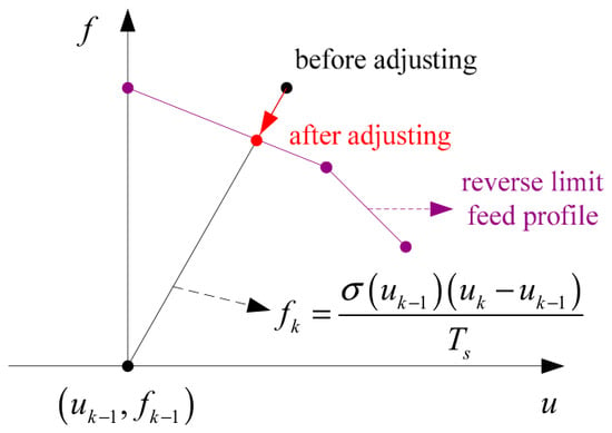
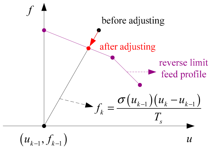
After obtaining , the feedrate is compared with the reverse limit feedrate profile. Two adjacent reverse feedrate points, and (), were selected. Then, the feedrate constraint from the reverse feedrate profile at is assessed as:
Figure 5.
Adjust the optimal feedrate within reverse feedrate limit.
Upon deriving the feedrate and parameter for the current CCB, the interpolation point is computed, and the motion command for each axis is updated accordingly.
4. Simulation and Experimental Validation
4.1. Development of the Corner Smoothing System
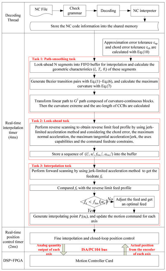
To realize the proposed methodology, an integrated online corner smoothing system was developed in this research. Figure 6 depicts the architectural design of the look-ahead interpolator and motion controller. Both simulation and experimental validation were performed on a three-axis machine tool, model XK714. The proprietary CNC system is PC-based, facilitating convenient installation and execution of the proposed interpolation algorithm. This CNC platform employs the Windows XP operating system combined with Venturecom’s RTX 6.1, enabling real-time computation and multitasking capabilities. As discussed in preceding sections, three critical components must be addressed when implementing the online path-smoothing method for CNC machining: the path-smoothing scheme, the look-ahead function, and the interpolation algorithm. Consequently, the optimal feedrate scheduling interpolator comprises three principal tasks. The first task is the path-smoothing function, which rounds the corners of linear segments using Bézier transition pairs based on the optimal error assignment algorithm. Within the blending algorithm, both approximation error and chord error are constrained simultaneously, while the approximation error and curvature extremum of the Bézier transition pair can be derived analytically.
Figure 6.
System architecture of the proposed interpolator and motion controller.
This produces a sequence of curvature-continuous blocks consisting of residual lines and Bézier transition curves, resulting in a G2-continuous toolpath. The second task is the look-ahead function. Reverse scanning is executed from the look-ahead window’s termination to its initiation, generating the reverse limit feedrate profile. The third task is the interpolation function. Based on the acquired feedrate constraints, forward scanning generates an optimal feedrate profile utilizing the jerk-limited acceleration strategy. Subsequently, interpolation points are generated according to the current displacement to estimate the curve parameter.
4.2. Simulation for the Proposed Interpolator
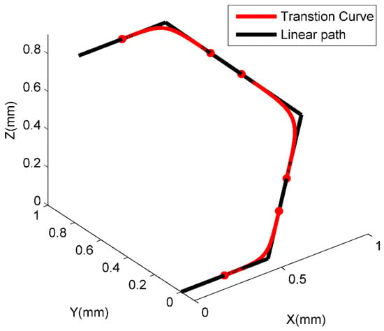
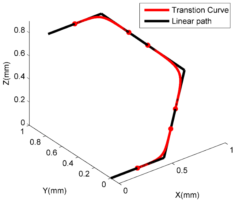
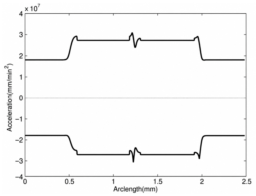
A linear toolpath defined by five points: {(0, 0, 0), (0.5, 0, 0), (1, 0.4, 0.4), (0.6, 0.9, 0.8), (0.1, 0.9, 0.8)} mm serves as the test case, as illustrated in Figure 7. To demonstrate the performance of the proposed interpolator, the position deviation tolerance is set to 0.05 mm, and the sampling period Ts is 0.004 s. To maintain consistency with the sampling period, the dynamic parameters are expressed using seconds as the time unit: the acceleration limits for each axis and the maximum normal acceleration are both constrained to 5000 mm/s2 (equivalent to 1.8 × 107 mm/min2), while the feedrate limitation per axis is set to 100 mm/s (equivalent to 6000 mm/min). The command feedrate is 83.33 mm/s (equivalent to 5000 mm/min). Feedrate values in the figures may also be shown in mm/min for consistency with common CNC display conventions.
Figure 7.
G2 continuous transition curves for 3D linear toolpath.
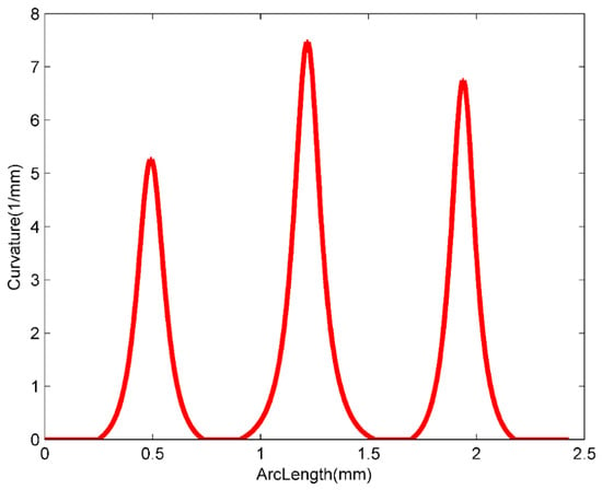
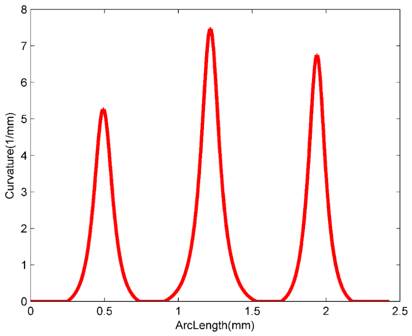
The maximal approximation error and the maximal chord error are calculated by Equation (10). According to , and . The proposed path-smoothing algorithm is applied to the 3D linear toolpath. Three Bézier transition pairs (red line in Figure 7) are obtained at the corners. Figure 8 shows the new toolpath is curvature-continuous.
Figure 8.
Curvature of G2 continuous toolpath.
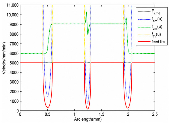
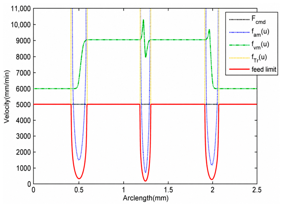
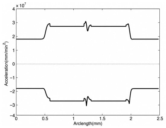
In the simulation, Equation (10) is first used to obtain the optimal allocation of the prescribed tolerance. Then, Equations (12) and (13) are used to calculate the transitional feedrate constrained by chord error and normal acceleration, respectively. The axis velocity and acceleration constraints are evaluated using Equations (18) and (20), and the final feasible feedrate profile is obtained through Equation (21). Figure 9 demonstrates that the generated feedrate remains bounded by both the maximal transitional feedrate profile, fTr(u), and the maximum feasible feedrate profile, facc(u). As illustrated in Figure 10, the actual acceleration is concurrently maintained within the specified acceleration limits.
Figure 9.
Feedrate limit profile of the proposed interpolator.
Figure 10.
Acceleration limit profile of the proposed interpolator.
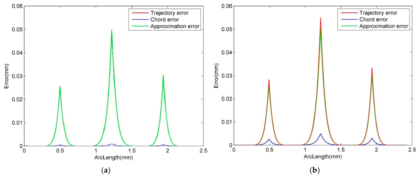
Fourth, the proposed interpolation method is used to interpolate the new G2-continuous toolpath. To further clarify the difference between the proposed method and the method in ref. [19], a direct trajectory-error comparison was conducted using the same specified 3D toolpath. Since the current CNC platform cannot synchronously record complete servo tracking-error data, this comparison was conducted through offline trajectory-error calculation using the same interpolation period, dynamic constraints, and prescribed tolerance. Therefore, the comparison focuses on the geometric and interpolation-induced trajectory errors rather than closed-loop servo tracking errors.
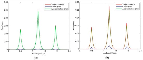
Figure 11 compares the three error profiles generated by the proposed method and the method in ref. [19]. As shown in Figure 11a, the trajectory error, chord error, and approximation error generated by the proposed interpolator are all constrained within the predefined tolerance of 0.05 mm. This result demonstrates the effectiveness of the proposed optimal error assignment algorithm in controlling the total trajectory error.
Figure 11.
Comparison of the three error profiles generated by the proposed method and the method in ref. [19] on the same specified 3D toolpath. (a) Proposed method; (b) method in ref. [19].
In contrast, Figure 11b presents the three error profiles generated by the method in ref. [19]. This method is used here as a representative NURBS interpolation strategy, which focuses on adaptive real-time NURBS interpolation and restricts the chord error and approximation error separately. However, because these two error components are not allocated under a unified trajectory-error model, the accumulated trajectory deviation may exceed the prescribed tolerance in local regions. By comparison, the proposed method uses dual cubic Bézier transition curves with analytical curvature evaluation and assigns the allowable tolerance between the approximation error and chord error through Equation (10). Therefore, the total trajectory error, rather than only the individual error components, can be explicitly controlled.
4.3. Experiment for the Proposed Interpolator
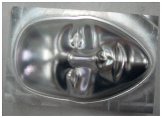
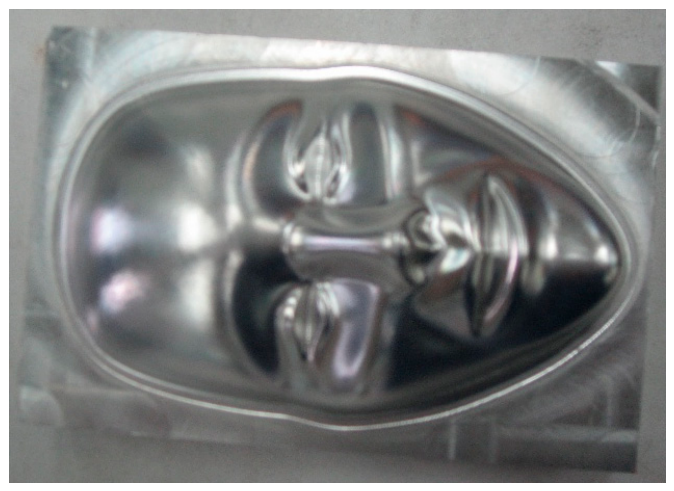
Experimental validation of the proposed interpolator’s advantages is conducted through the machining of a mask component, as illustrated in Figure 12. The workpiece is a rectangular aluminum stock. The machining parameters are configured using seconds as the time unit: the command feedrate is 25 mm/s (1500 mm/min), the maximum acceleration is constrained to 300 mm/s2 (1.08 × 106 mm/min2), the maximum jerk is limited to 3750 mm/s3 (8.1 × 108 mm/min3), and the sampling period Ts is 0.004 s. The look-ahead buffer is set to a maximum of 50 blocks, and the predefined position tolerance is 0.001 mm. Rough machining is performed using a 10 mm diameter flat-end mill, followed by finish machining with a 6 mm diameter ball-end cutter.
Figure 12.
A mask after finish machining.
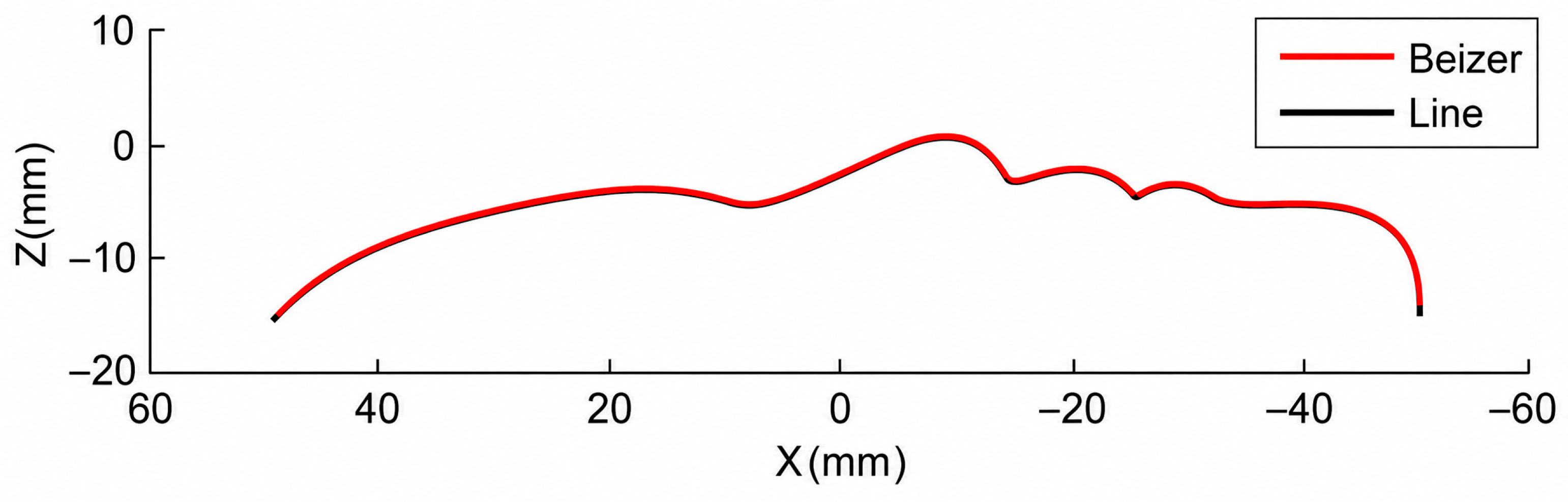
The toolpath to machine the mask is composed of tens of thousands of linear segments. For verification, 225 consecutive linear segments from the mask finish-machining toolpath, shown in Figure 13, are selected. To evaluate performance, three interpolation strategies are tested within the machine tool’s open CNC system, all based on jerk-limited acceleration principles. The first strategy has no look-ahead function and therefore decelerates strongly at each segment junction. The second strategy incorporates look-ahead planning, which improves feedrate scheduling, but it does not eliminate the tangent and curvature discontinuities of the original linear toolpath. The third strategy is the proposed method, which combines look-ahead feedrate planning with G2-continuous corner smoothing.
Figure 13.
G2 continuous transition curves for 225 linear segments of a mask.
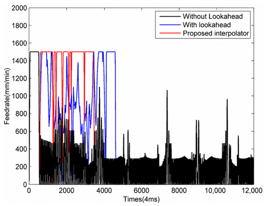
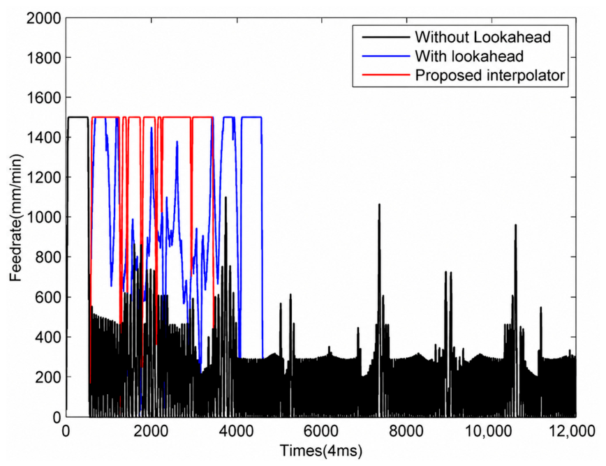
Figure 14 depicts the simulated feedrate profiles generated by these three methods. In the first method, the feedrate at segment junctions drops close to zero but does not become exactly zero because a jerk-limited acceleration/deceleration profile is still imposed by the controller. The incorporation of a look-ahead function in the second method mitigates these cornering speed reductions, thereby significantly reducing machining time compared with the first method, as detailed in Table 1.
Figure 14.
Feedrate profiles corresponding to the three interpolation methods.
Table 1.
Machining time of the three interpolation methods.
However, because the geometric discontinuities of the original G01 blocks remain, noticeable feedrate and acceleration fluctuations still occur. In contrast, the proposed interpolator converts the linear toolpath into a curvature-continuous trajectory, effectively eliminating both tangential and curvature discontinuities. Consequently, the resulting feedrate profile is substantially smoother and tracks the command feedrate of 25 mm/s (1500 mm/min) more closely. As evidenced by Figure 14 and Table 1, the total machining time for the proposed method is 13.9 s, representing reductions of approximately 70% and 25% relative to the first and second methods, respectively.
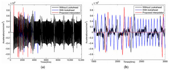
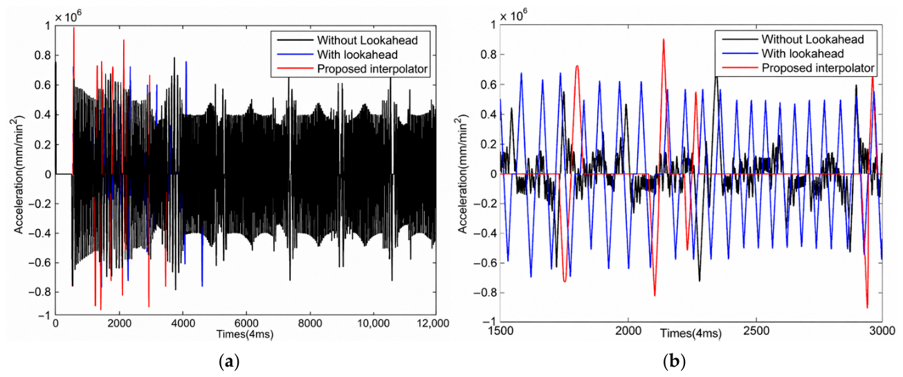
Figure 15 presents the corresponding acceleration profiles. The first method exhibits severe acceleration fluctuations due to the frequent stop-start cycles of the feed motors at every corner. While the look-ahead function in the second method alleviates the frequency of these stop-start events, the underlying discontinuities still induce noticeable acceleration fluctuations. Conversely, the acceleration profile of the proposed third method is markedly smoother, as shown in Figure 15.
Figure 15.
Acceleration profiles corresponding to the three interpolation methods. (a) The whole profiles; (b) profiles from 1500th to 3000th periods.
It should be noted that the present experimental validation is a proof-of-concept verification based on one representative mask-machining toolpath. Since the current open CNC platform cannot synchronously record complete servo tracking-error data, the trajectory-error comparison with the method in ref. [19] was conducted using the same specified 3D path data through offline calculation, as shown in Figure 11. Therefore, the experimental part mainly evaluates the proposed method in terms of feedrate smoothness, acceleration smoothness, and machining time, while the trajectory-error control capability is verified through simulation-based error evaluation. Additional tests involving freeform paths, high-curvature paths, and sharp-corner paths, as well as direct comparisons with commercial CNC smoothing functions, will be conducted in future work when broader machine access and servo data acquisition are available.
5. Summary and Conclusions
In high-precision machining, complex surfaces are predominantly approximated using linear toolpaths composed of G01 blocks. The tangent and curvature discontinuities at segment junctions restrict high-speed, high-accuracy motion and may introduce feedrate fluctuation and contouring error. To address this challenge, this paper presents a real-time corner smoothing methodology integrated with an online analytical feedrate interpolator. The proposed framework comprises a dual cubic Bézier path-smoothing module, an optimal error assignment module, and a jerk-limited look-ahead interpolation module. Based on the simulation and mask-machining validation, the main findings are summarized as follows:
- (1)
- The proposed optimal error assignment model constrains the approximation error, chord error, and total trajectory error within the preset tolerance of 0.05 mm in the three-dimensional simulation case. The comparison with the method in ref. [19] further confirms that the proposed optimal error assignment model provides more explicit control of the total trajectory error than methods that constrain the approximation error and chord error separately.
- (2)
- Compared with the method without look-ahead and the method with look-ahead only, the proposed interpolator generates smoother feedrate and acceleration profiles by removing tangency and curvature discontinuities.
- (3)
- In the mask-machining case, the machining time is reduced to 13.9 s, corresponding to reductions of approximately 70% and 25% relative to the two comparative methods.
- (4)
- The method is suitable for online implementation because the approximation error and maximum curvature of the transition curves are obtained analytically, and the optimal error allocation is calculated before interpolation.
Future work will focus on three aspects. First, more representative toolpaths, including freeform, high-curvature, and sharp-corner paths, will be tested to improve statistical robustness. Second, direct benchmarking against B-spline/NURBS smoothing, S-curve feedrate planning, and available commercial CNC smoothing functions will be conducted when reproducible implementation details and machine access are available. Third, the proposed real-time curvature-continuous transition algorithm will be extended to five-axis NC machining, where the synchronization of position and orientation curves must also be considered.
Author Contributions
H.X. was mainly responsible for experimental data collection and text proofreading of the paper. X.L. was mainly responsible for experimental scheme design and trial result analysis. S.W. proposed the concept of the paper and coordinated the organization of writing work. L.L. was mainly responsible for manuscript writing, proofreading, and experimental result analysis. All authors have read and agreed to the published version of the manuscript.
Funding
This research was funded by the National Nature Science Foundation of China (No. 52075392).
Data Availability Statement
Data used for the paper are currently unavailable.
Conflicts of Interest
The authors declare no conflicts of interest.
Nomenclature
| Symbol | Description | Symbol | Description |
| The i-th point of the original linear toolpath | Radius of curvature of the i-th curve | ||
| The i-th curvature-continuous block or curve segment | Minimum radius of curvature | ||
| Curve parameter | Feedrate along the i-th CCB | ||
| Interpolation period of the CNC system | Displacement of the Λ-axis on the i-th curve | ||
| Maximum normal acceleration capacity of the machine tool | Velocity of the Λ-axis on the i-th curve | ||
| Commanded feedrate specified by the programmer | Acceleration of theΛ-axis on the i-th curve | ||
| Approximation error of the corner transition | Maximum allowable chord error | ||
| Maximum allowable approximation error | Prescribed maximum trajectory tolerance | ||
| Maximum curvature of the transition curve | CCB | Curvature-continuous block |
Appendix A
Detailed processes for deducing G2 Bézier transition algorithm
The two line segments are determined by points , , and . Their unit direction vectors are and , and the angle between the two-unit vectors is . While the two transition lengths are the same () and , the Bézier transition curve is defined as Equation (A3). The approximation error at the segment junction is analytically computed with Equation (A4). When the maximal approximation error is set to , the transition length is restricted by Equation (A5). The maximal curvature in the transition Bézier, which is critical for velocity planning, is also analytically computed with Equation (A6).
Figure A1.
Neighboring line segments smoothed by a cubic Bézier curve.
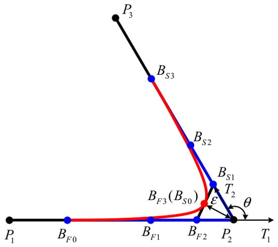
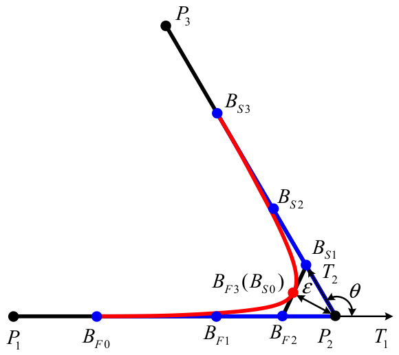
To be convenient for interpolation, the transition Bézier (defined by control points ) is split into two halves at the maximum curvature point. Each half is still a cubic Bézier. The points BF0, BF1, BF2, and BF3 are the control points for the first half; similarly, BS0, BS1, BS2, and BS3 are control points for the second half, as shown in Figure 3.
Substituting Equation (A2) into Equations (A7) and (A8) leads to
References
- Tajima, S.; Sencer, B. Global tool-path smoothing for CNC machine tools with uninterrupted acceleration. Int. J. Mach. Tools Manuf. 2017, 121, 81–95. [Google Scholar] [CrossRef] [Scilit]
- Zhang, Q.; Gao, X.S.; Li, H.B.; Zhao, M.Y. Minimum time corner transition algorithm with confined feedrate and axial acceleration for nc machining along linear toolpath. Int. J. Adv. Manuf. Technol. 2016, 89, 941–956. [Google Scholar] [CrossRef] [Scilit]
- Xu, J.; Li, Y.; Zhou, D.; Chen, J. Research on B-spline smoothing compression and G2-continuous blending algorithm for continuous short line segment tool paths. In 2024 4th International Conference on Electrical Engineering and Mechatronics Technology (ICEEMT); IEEE: New York, NY, USA, 2024; pp. 253–259. [Google Scholar]
- Khoshdarregi, M.R.; Tappe, S.; Altintas, Y. Integrated Five-Axis Trajectory Shaping and Contour Error Compensation for High-Speed CNC Machine Tools. IEEE/ASME Trans. Mechatron. 2014, 19, 1859–1871. [Google Scholar] [CrossRef] [Scilit]
- Hu, Y.; Jiang, X.; Huo, G.; Su, C.; Zhou, S.; Wang, B.; Li, H.; Zheng, Z. A novel feedrate scheduling method with acc-jerk-continuity and round-off error elimination for non-uniform rational B-spline interpolation. J. Comput. Des. Eng. 2023, 10, 294–317. [Google Scholar]
- Beudaert, X.; Pechard, P.Y.; Tournier, C. 5-Axis toolpath smoothing based on drive constraints. Int. J. Mach. Tools Manuf. 2011, 51, 958–965. [Google Scholar] [CrossRef] [Scilit]
- Yang, Z.; Shen, L.Y.; Yuan, C.M.; Gao, X.S. Curve fitting and optimal interpolation for CNC machining under confined error using quadratic B-splines. Comput.-Aided Des. 2015, 66, 62–72. [Google Scholar] [CrossRef] [Scilit]
- Bi, Q.Z.; Shi, J.; Wang, Y.H.; Zhu, L.; Ding, H. Analytical curvature-continuous dual-Bézier corner transition for five-axis linear toolpath. Int. J. Mach. Tools Manuf. 2015, 91, 96–108. [Google Scholar] [CrossRef] [Scilit]
- Tang, P.Y.; Lin, M.T.; Tsai, M.S.; Cheng, C.C. Toolpath interpolation with novel corner smoothing technique. Robot. Comput.-Integr. Manuf. 2022, 78, 102388. [Google Scholar] [CrossRef] [Scilit]
- Hua, L.; Huang, N.; Yi, B.; Zhao, Y.; Zhu, L. Global toolpath smoothing for CNC machining based on B-spline approximation with tool tip position adjustment. Int. J. Adv. Manuf. Technol. 2023, 125, 3651–3665. [Google Scholar] [CrossRef] [Scilit]
- Yang, X.; You, Y. Linear tool path-smoothing method in high-speed machining based on error feasible area and curvature optimization. Appl. Sci. 2022, 12, 9443. [Google Scholar] [CrossRef] [Scilit]
- Zhang, L.B.; You, Y.P.; He, J.; Yang, X.F. The transition algorithm based on parametric spline curve for high-speed machining of continuous short line segments. Int. J. Adv. Manuf. Technol. 2011, 52, 245–254. [Google Scholar] [CrossRef] [Scilit]
- Yau, H.T.; Wang, J.B. Fast Bezier interpolator with real-time lookahead function for high-accuracy machining. Int. J. Mach. Tools Manuf. 2007, 47, 1518–1529. [Google Scholar] [CrossRef] [Scilit]
- Emami, M.M.; Arezoo, B. A look-ahead command generator with control over trajectory and chord error for NURBS curve with unknown arc length. Comput.-Aided Des. 2010, 42, 625–632. [Google Scholar] [CrossRef] [Scilit]
- Nie, M.; Wan, Y.; Zhou, A. Real-Time NURBS Interpolation Under Multiple Constraints. Comput. Intell. Neurosci. 2022, 2022, 7492762. [Google Scholar] [CrossRef] [Scilit]
- Sun, S.; Lin, H.; Zheng, L.; Yu, J.; Hu, Y. A real-time and look-ahead interpolation methodology with dynamic B-spline transition scheme for CNC machining of short line segments. Int. J. Adv. Manuf. Technol. 2016, 84, 1359–1370. [Google Scholar] [CrossRef] [Scilit]
- Tajima, S.; Sencer, B. Kinematic corner smoothing for high speed machine tools. Int. J. Mach. Tools Manuf. 2016, 108, 27–43. [Google Scholar] [CrossRef] [Scilit]
- Sencer, B.; Tajima, S. Frequency Optimal Feedrate Motion Planning in Computer Numerical Controlled Machine Tools for Vibration Avoidance. J. Manuf. Sci. Eng. 2017, 139, 011006. [Google Scholar] [CrossRef] [Scilit]
- Ji, S.; Lei, L.; Zhao, J.; Lu, X.; Gao, H. An adaptive real-time NURBS curve interpolation for 4-axis polishing machine tool. Robot. Comput.-Integr. Manuf. 2021, 67, 102025. [Google Scholar] [CrossRef] [Scilit]
- Tulsyan, S.; Altintas, Y. Local toolpath smoothing for five-axis machine tools. Int. J. Mach. Tools Manuf. 2015, 96, 15–26. [Google Scholar] [CrossRef] [Scilit]
- Shi, J.; Bi, Q.Z.; Zhu, L.M.; Wang, Y. Corner rounding of linear five-axis toolpath by dual PH curves blending. Int. J. Mach. Tools Manuf. 2015, 88, 223–236. [Google Scholar] [CrossRef] [Scilit]
- Huang, N.; Hua, L.; Huang, X.; Zhang, Y.; Zhu, L.; Biermann, D. B-spline-based corner smoothing method to decrease the maximum curvature of the transition curve. J. Manuf. Sci. Eng. 2022, 144, 054503. [Google Scholar] [CrossRef] [Scilit]

Disclaimer/Publisher’s Note: The statements, opinions and data contained in all publications are solely those of the individual author(s) and contributor(s) and not of MDPI and/or the editor(s). MDPI and/or the editor(s) disclaim responsibility for any injury to people or property resulting from any ideas, methods, instructions or products referred to in the content. |
© 2026 by the authors. Licensee MDPI, Basel, Switzerland. This article is an open access article distributed under the terms and conditions of the Creative Commons Attribution (CC BY) license.