


Abstract
This paper presents a deployment-oriented longitudinal platoon-control architecture for connected and autonomous vehicles operating under repeated leader hard-braking, cut-ins, and spatially varying road friction. The proposed stack combines four elements: (i) a lightweight scalar Kalman filter (KF) that smooths a friction-related signal and feeds friction-dependent constraint tightening; (ii) a model predictive control (MPC) backbone whose weights and horizon are selected offline using multi-objective GA/NSGA-II tuning; (iii) a bounded proximal policy optimization (PPO) residual policy, trained with the aid of a learned surrogate model, that refines the MPC command during transient events; and (iv) a command-level safety projection that enforces instantaneous actuation and clearance constraints at the fast control tick. The contribution is therefore not a new MPC formulation or a new reinforcement-learning algorithm in isolation, but an integrated and experimentally characterized control stack that keeps the safety-critical structure explicit while using learning to improve transient behavior. The method is evaluated in a CARLA digital twin of a six-vehicle platoon over a 5 km mixed urban–highway route and is further assessed in hardware-in-the-loop (HIL) on an automotive ECU using a multi-rate ROS 2/AUTOSAR implementation (50 Hz estimation/safety loop, 10 Hz MPC/RL refresh). Across 10 held-out disturbance seeds, the full stack improves spacing regulation, maintains non-amplifying disturbance propagation according to the reported string-stability indices, and reduces a route-normalized positive tractive-energy-at-the-wheels proxy by about 12% relative to Manual MPC and by up to 18% relative to a PID-CACC reference. Because the PID-CACC baseline does not enforce hard constraints and can collide under the tested disturbance suite, the main performance comparison is among collision-free controllers. The friction signal used in CARLA is derived from simulator road-surface annotations before filtering, so the present study should be interpreted as a friction-aware control and integration study rather than a validated onboard friction-estimation result. Likewise, the reported energy metric is an effort proxy and is not a calibrated fuel or battery consumption model.
1. Introduction
Connected and autonomous vehicle platooning can improve road throughput, safety, and energy efficiency by coordinating inter-vehicle spacing and reducing unnecessary acceleration–braking cycles [1,2,3,4,5,6]. Its deployment remains difficult because a longitudinal controller must maintain spacing and string stability while reacting to leader hard-braking, cut-ins, sensing/communication uncertainty, and spatially varying tire–road friction. We use string stability in the operational sense that disturbances should not amplify along the vehicle index: frequency-domain gains should remain below unity over the relevant band, and the time-domain variance ratio should remain below one, where is the spacing error [7,8,9,10,11,12].
The central motivation of this paper is the gap between high-performing learning-based platoon controllers and the auditability required for embedded vehicle control. Pure model-free RL can improve transient behavior, yet it is difficult to certify if it commands acceleration directly. Conversely, constrained MPC supplies an explicit feasibility envelope but can be conservative and sensitive to weight tuning [2,13,14,15,16,17]. This motivates the research question addressed here: can a learned residual improve cut-in and braking transients while an explicit MPC backbone, friction-aware actuation limits, and a fast safety projection retain authority over hard constraints?
We answer this question with a deployment-oriented hierarchical stack. A scalar KF smooths a friction-related signal and uses it only to tighten actuation and clearance constraints; a GA/NSGA-II-tuned MPC provides the conservative acceleration command; a bounded PPO residual improves short transients; and a 50 Hz command-level shield projects the raw MPC + RL proposal onto the instantaneous admissible set. The contribution is therefore not a new MPC formulation, PPO algorithm, lane-change planner, or validated tire-friction estimator. It is the integration and experimental characterization of a safety-filtered residual-learning architecture whose component responsibilities are explicitly separated. Table 1 summarizes the task boundary between controller layers before the table is presented.
Table 1.
Task boundary between the MPC, RL residual, KF, and safety shield. The learned component is a performance-refinement layer, not the safety authority.
The evaluation uses a six-vehicle platoon on a 5 km CARLA mixed urban–highway route with repeated hard-braking, random cut-ins/cut-outs, and friction variation . The complete multi-rate stack is also executed in HIL on an automotive ECU with ROS 2/AUTOSAR timing instrumentation. Across held-out disturbance seeds, the proposed stack is compared with PID-CACC, Manual MPC, and internal ablations that isolate KF tightening, GA tuning, and the PPO residual.
The main contributions are: (i) a friction-as-constraints hierarchical controller with a runtime safety projection; (ii) a fixed disturbance-rich CARLA/HIL evaluation protocol with train/validation/test seed separation; (iii) measured ECU latency/jitter and deadline-miss reporting for the multi-rate implementation; and (iv) ablations that quantify where the learned residual adds value beyond tuned MPC. The study is scoped to longitudinal, single-lane platooning, CARLA actor states provide the kinematic and intruder-distance features, friction observations are derived from simulator road-surface annotations, and the reported efficiency metric is a positive tractive-energy-at-the-wheels proxy rather than calibrated fuel or battery consumption. All computations use SI units.
2. Related Work
2.1. Longitudinal Platoon Control and Constrained MPC
Classical ACC/CACC controllers maintain spacing through feedback and, when available, V2V feedforward. Experimental and traffic-flow studies show that CACC can improve flow characteristics when communication and sensing assumptions hold [4,18], while foundational ACC/CACC analyses define the string-stability requirement that leader or traffic disturbances should not amplify downstream [7,8,9,10,11,12]. Constant-time-headway policies improve this behavior but remain sensitive to sensing noise, delays, actuator limits, communication bursts or dropouts, attacks, and vehicle heterogeneity [6,11,19,20,21,22,23,24]. These limitations motivate constrained controllers that can explicitly encode clearance, comfort, actuation, and communication assumptions.
MPC is well suited to this role because it optimizes spacing, relative velocity, and control effort over a finite horizon while enforcing safety and actuation bounds. Prior platooning MPC studies have addressed fuel-efficient look-ahead coordination, tube/robust MPC, data-driven predictive control, switching-topology platoons, and distributed receding-horizon string-stability analysis [2,13,15,16,17,25]. Recent vehicle-control MPC work likewise emphasizes the trade-off between tracking accuracy and real-time feasibility, including computationally efficient path-tracking formulations [26]. However, MPC performance depends on prediction fidelity, horizon length, weight selection, and solver timing; parameter-space robust-control ideas and modern automatic tuning studies motivate systematic controller-parameter selection rather than purely manual calibration [14,27,28,29,30]. The present work therefore uses MPC as the conservative backbone and selects its weights/horizon offline with a multi-objective GA/NSGA-II procedure rather than relying only on manual tuning.
2.2. Learning-Enhanced and Safety-Filtered Platooning
Deep RL, supervised RL, Dyna-style/model-based learning, and MARL have been used for CACC/platooning because learned policies can improve transient behavior under nonlinear disturbances, traffic oscillations, ramp regions, and mixed traffic interactions [1,31,32,33,34,35,36,37]. Interaction-aware trajectory-prediction studies further show that deep models can capture heterogeneous driving styles relevant to cut-ins [38]. Nevertheless, pure black-box policies are difficult to certify when their action directly commands acceleration. Hybrid model-based/learning designs address this concern by assigning feasibility to constrained control and performance refinement to learning, with safety-filtering concepts related to control-barrier-function and safe-RL formulations [39,40,41,42]. Our PPO component follows this conservative pattern: it is a bounded residual, not a replacement for MPC, and all raw MPC + RL commands are checked by a 50 Hz safety projection.
2.3. Cut-Ins, Lane-Change Planning, Tire–Road Interaction, and Command Shaping
The present controller is longitudinal. Cut-ins are exogenous lateral disturbances, and the platoon reacts only after an intruder is selected as the closest in-lane forward vehicle. Lane-change planners such as the hybrid Bezier/RRT approach of Skackauskas et al. treat a different problem—generating feasible lateral maneuvers under geometry and surrounding-vehicle constraints [43]. Our contribution is complementary: it evaluates how a constrained longitudinal platoon controller absorbs such lateral disturbances without collision or downstream amplification.
Friction modeling has a similar boundary. Tire–road interaction depends on load, inflation, deformation, pavement condition, slip, temperature, and contact mechanics; the tire simulation work of Karpenko et al. illustrates why real friction estimation requires validation against measurable vehicle/tire responses [44]. Accordingly, the CARLA road-surface annotation used here is treated only as a simulated friction-related observation for constraint tightening, not as a validated onboard friction-estimation result. Finally, low-complexity input-shaping or command-filtering methods can reduce known oscillatory modes with little computation [45,46,47]. They are valuable alternatives or auxiliary filters, but they do not by themselves provide the clearance, TTC-surrogate, and friction-coupled actuation constraints required in the disturbance-rich setting studied here.
Table 2 summarizes the related-work positioning before the table is presented.
Table 2.
Related-work positioning. The table clarifies that the novelty of this paper is an integrated deployment-oriented control stack rather than a new MPC, PPO, lane-change-planning, or friction-estimation algorithm.
2.4. Scientific Positioning of the Present Study
The closest antecedents are constrained MPC platoon controllers with explicit safety structure [2,13,15,17] and DRL/MARL CACC controllers that optimize multi-objective rewards without the same hard command-level projection [1,33,36,37]. The present paper does not claim a new MPC formulation, PPO algorithm, lane-change planner, or validated tire-friction estimator. Its contribution is the integrated, auditable allocation of responsibilities: friction information tightens constraints; MPC supplies the conservative command; PPO adds a bounded transient residual; the fast shield admits only feasible commands when the projection problem is feasible; and the complete multi-rate stack is evaluated with ablations, held-out disturbance seeds, and ECU timing measurements.
3. System Overview
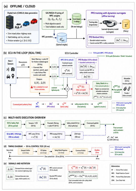
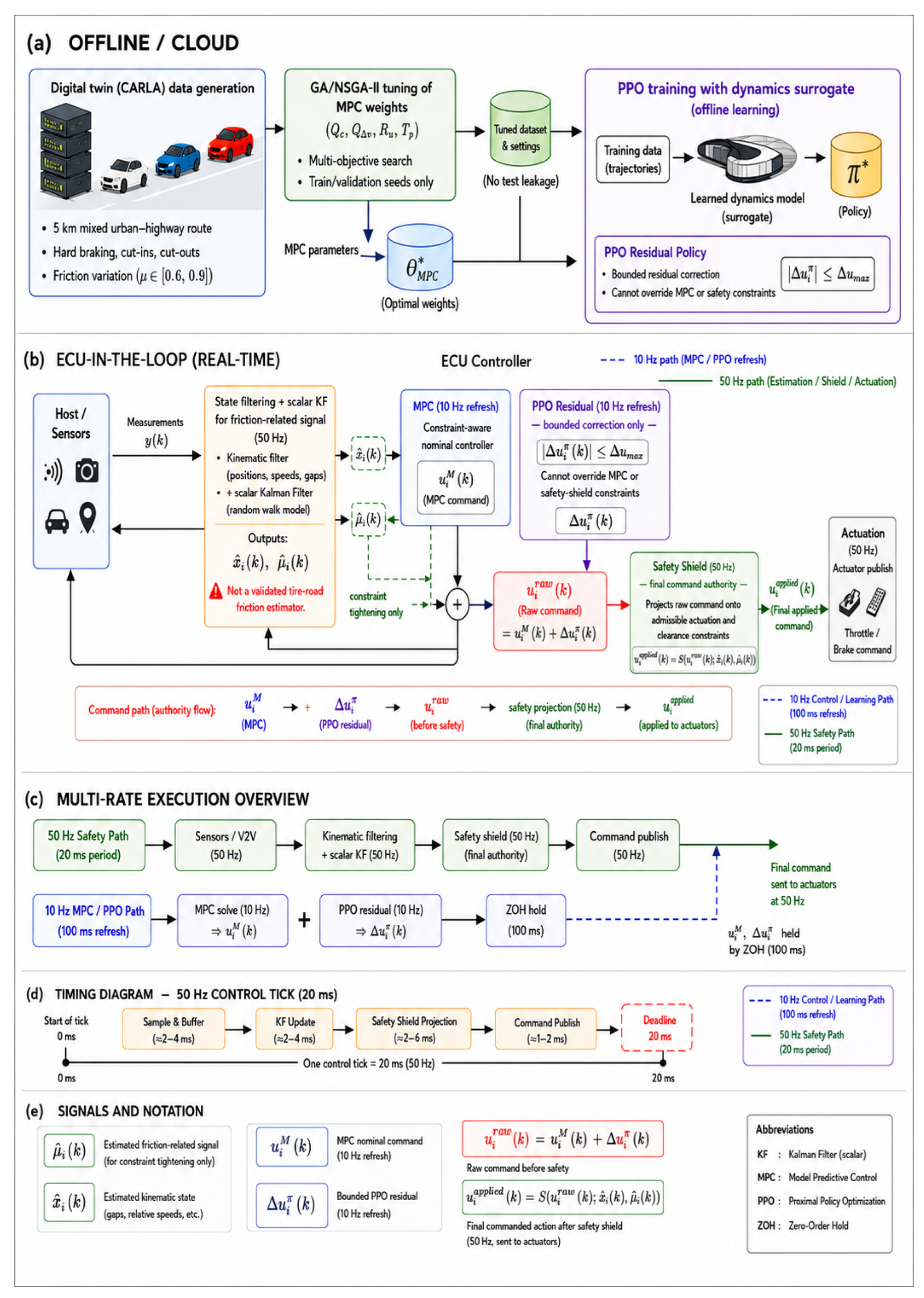
Figure 1 summarizes the offline and online pipeline.
Figure 1.
Overall architecture and multi-rate execution of the proposed safety-filtered residual-learning controller. (a) Offline/cloud workflow for CARLA data generation, GA/NSGA-II tuning of MPC weights, and PPO residual-policy training with a learned dynamics surrogate. (b) Real-time ECU-in-the-loop control architecture. The MPC provides the nominal command , the PPO policy supplies only a bounded residual correction , and the raw command is projected by the 50 Hz safety shield before actuation. The safety shield is the final command authority. (c) Multi-rate execution structure separating the 50 Hz estimation/safety/actuation path from the 10 Hz MPC/PPO refresh path. (d) Timing diagram for one 20 ms control tick. (e) Signal notation used throughout the controller. The KF-smoothed friction-related signal is used only for constraint tightening and should not be interpreted as a validated onboard tire-road friction estimator.
Offline, representative CARLA disturbance seeds are used to tune the MPC parameters by GA/NSGA-II and to train the PPO residual with surrogate-augmented rollouts. Online, each follower ECU receives/filters kinematic data, updates the friction KF, refreshes MPC and PPO commands at 10 Hz, and applies a 50 Hz safety projection before publishing the longitudinal command. The six vehicles are denoted , with as the externally driven leader and , , controlled by the proposed follower stack. The desired spacing policy is
where r is standstill distance and h is the time headway. Each follower uses the filtered state , the friction estimate , and the nearest in-lane forward object (nominal predecessor or cut-in intruder). The MPC output is the primary constrained command. The PPO policy proposes only a bounded residual, giving
and the residual is held by zero-order hold between 10 Hz refreshes. We log , , , the applied command, and shield activation so that the incremental role of learning is auditable.
3.1. Command-Level Safety Projection
At every 50 Hz control tick, the raw proposal is passed through a scalar projection
implemented as the one-step QP
Here and with ms. The index is the closest in-lane forward vehicle at the current tick. Because all constraints in (4) are affine in the scalar command u, the admissible set is an interval and the projection can be implemented equivalently as a scalar clipping operation,
where
If the QP is feasible and the raw command already satisfies the inequalities, the shield is an identity map. If the current state is already infeasible (e.g., an abrupt cut-in produces ), the deterministic fallback is applied and the event is logged. This fallback is a damage-limiting emergency action and does not by itself guarantee that feasibility is immediately restored. The shield is therefore a one-step input-feasibility contract rather than an infinite-horizon invariance theorem; chattering is monitored through shield activation fraction, acceleration standard deviation, jerk, and peak deceleration in Section 6.
3.2. Communication and Real-Time Schedule
Followers use local kinematics and, when available, V2V predecessor acceleration. Missing predecessor acceleration is handled by a constant-velocity preview ; hard constraints remain enforced by MPC and the shield. The HIL prototype runs as ROS 2 nodes on an automotive ECU. Sensor buffering, kinematic filtering, the friction KF, safety projection, and command publication execute at 50 Hz, while MPC and PPO inference refresh at 10 Hz. Table 3 gives the schedule. Policy and surrogate training are offline only.
Table 3.
Multi-rate schedule and signal exchange.
All reported latency and jitter values are wall-clock ECU measurements. The current prototype solves the convex MPC QP with warm-started SLSQP for engineering convenience; the formulation is solver-agnostic and intended to transfer directly to embedded QP solvers such as OSQP, qpOASES, acados, or generated code.
4. Methodology
This section gives the mathematical model used online and the offline procedures used for tuning and training. Details that are not required to interpret the main results are summarized in the reproducibility manifest.
4.1. Vehicle Model and Friction Filtering
Following standard longitudinal vehicle-dynamics and propulsion-modeling practice [48,49], the longitudinal point-mass model is
with friction-limited acceleration enforced through explicit bounds defined below. For inter-vehicle control, we use the state , where and . The continuous kinematics are and .
Motivated by Kalman-filter and adaptive-filter uses in vehicle estimation and CACC robustness [23,50,51], the friction-related observation is filtered with a scalar random-walk KF,
where is derived from CARLA road-surface annotation in this study. The update is
We use , , and at 50 Hz. With these values, the steady-state gain is about 0.181, giving an effective response time of approximately 0.10 s and a 95% step settling time of approximately 0.30 s. This quantifies smoothing and delay only; it is not a claim of real-vehicle friction-identification accuracy. Before constraint use, the filtered value is saturated to the physically admissible interval,
where subsequent notation writes for the clipped value. The friction-dependent acceleration limits used by both MPC and the 50 Hz shield are
where and are the calibrated braking and propulsion acceleration limits, and are friction-utilization factors, and g is gravitational acceleration.
4.2. MPC Formulation and GA/NSGA-II Tuning
At each 10 Hz refresh, the MPC predicts with s over steps. The discrete prediction model is
The QP cost is
subject to the model, speed limits, and the hard constraints
where the TTC-surrogate threshold tightens on low-friction segments,
For the reported experiments, is frozen at the current filtered friction value over each MPC horizon and updated at the next controller refresh. The solver is warm-started by shifting the previous solution, capped to respect the 10 Hz refresh budget, and only the first control value is applied before the next refresh. Table 4 lists the fixed controller and safety-constraint parameters used in the reported experiments.
Table 4.
Core controller and safety-constraint parameters used in the reported experiments. Controller-specific headways are selected per controller on validation seeds.
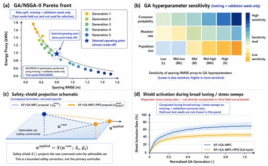
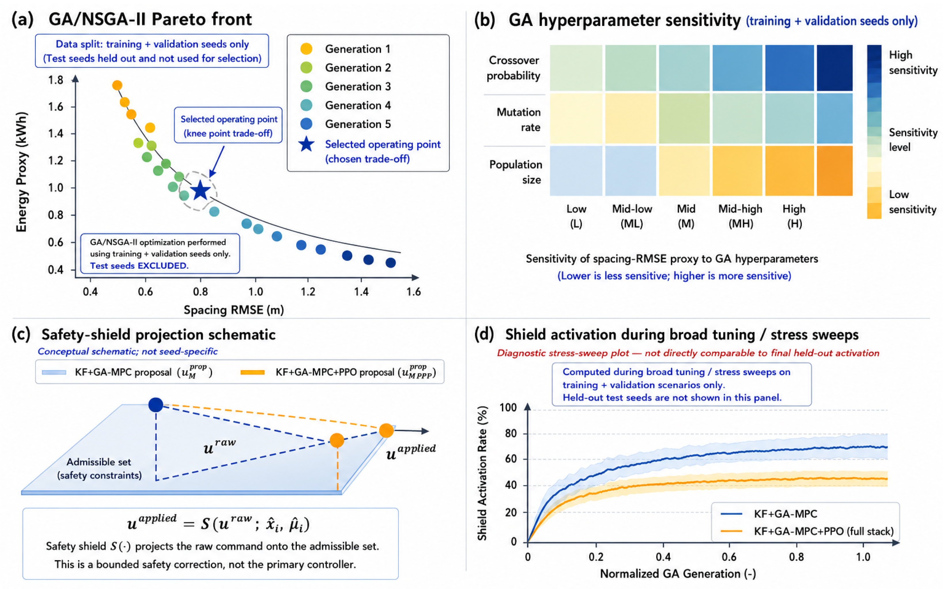
GA/NSGA-II tuning selects , , , , and using training/validation seeds and two competing objectives: spacing error and the tractive-energy proxy. Figure 2 shows the final trade-off. The selected validation operating point uses , , , s, and ; these values are fixed for the held-out test seeds.
Figure 2.
GA/NSGA-II tuning, sensitivity analysis, and safety-shield projection concept. (a) Pareto front used to select the operating point for the MPC tuning problem. The selected knee-point trade-off is computed using training and validation seeds only; held-out test seeds are excluded from GA/NSGA-II selection. (b) Sensitivity of the spacing-RMSE proxy to GA hyperparameters over the training/validation tuning set. (c) Conceptual safety-shield projection from the raw proposed command to the admissible applied command . The projection is a bounded safety correction and is not the primary controller. (d) Shield-activation behavior during broad tuning/stress sweeps. This panel is a diagnostic sweep over training/validation scenarios and is not directly comparable to the final held-out shield-activation rate reported in the evaluation results.
4.3. Residual PPO and Surrogate Training
The residual policy observes and outputs m/s2. The raw command is always shielded by Equation (3). At the 10 Hz MPC/RL refresh, the per-step reward is
where is the finite-difference jerk at the RL refresh, , and . The string-stability shaping term activates only during substantial upstream braking and penalizes follower over-braking relative to the nearest forward vehicle. The reward weights are reported in Table 5; they are fixed using training/validation seeds only, with all held-out test seeds excluded from reward, MPC, and policy-checkpoint selection.
Table 5.
PPO residual reward coefficients used in Equation (17). These weights define a validation-selected engineering reward for residual performance refinement; hard safety remains enforced by MPC constraints and the 50 Hz shield.
The surrogate model predicts one-step transitions for additional Dyna-style rollouts; its use is reduced as real simulator data become available, and online HIL runs execute only the trained forward policy. The surrogate-learning role is consistent with neural surrogate models and recurrent/dynamical forecasting approaches used to accelerate analysis or model-based learning [3,37,52].
4.4. Baseline Controllers for Comparison
We compare five controllers: PID-CACC, Manual MPC, GA-MPC, GA+KF, and the proposed KF+GA-MPC+PPO. PID-CACC is included as an interpretable classical reference, reflecting the long ACC/CACC and experimental platooning literature [4,10,18], but it lacks hard constraints and can collide in the most severe tests. The main performance comparisons are therefore interpreted primarily among collision-free constrained variants. All controllers use the same scenario seeds, route, vehicle model, and evaluation metrics.
5. Experimental Setup
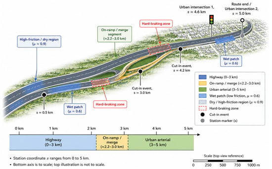
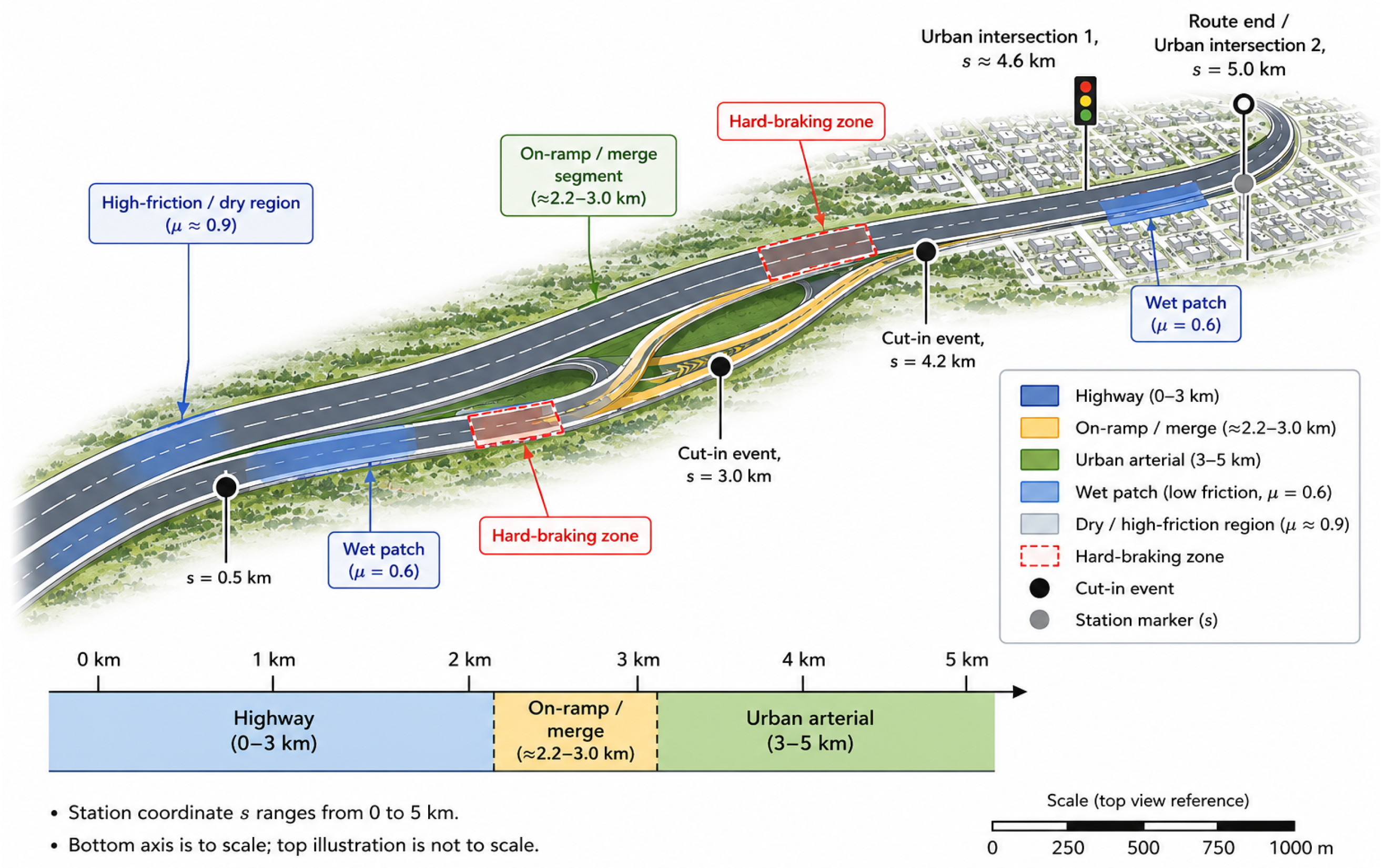
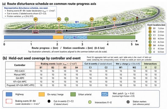
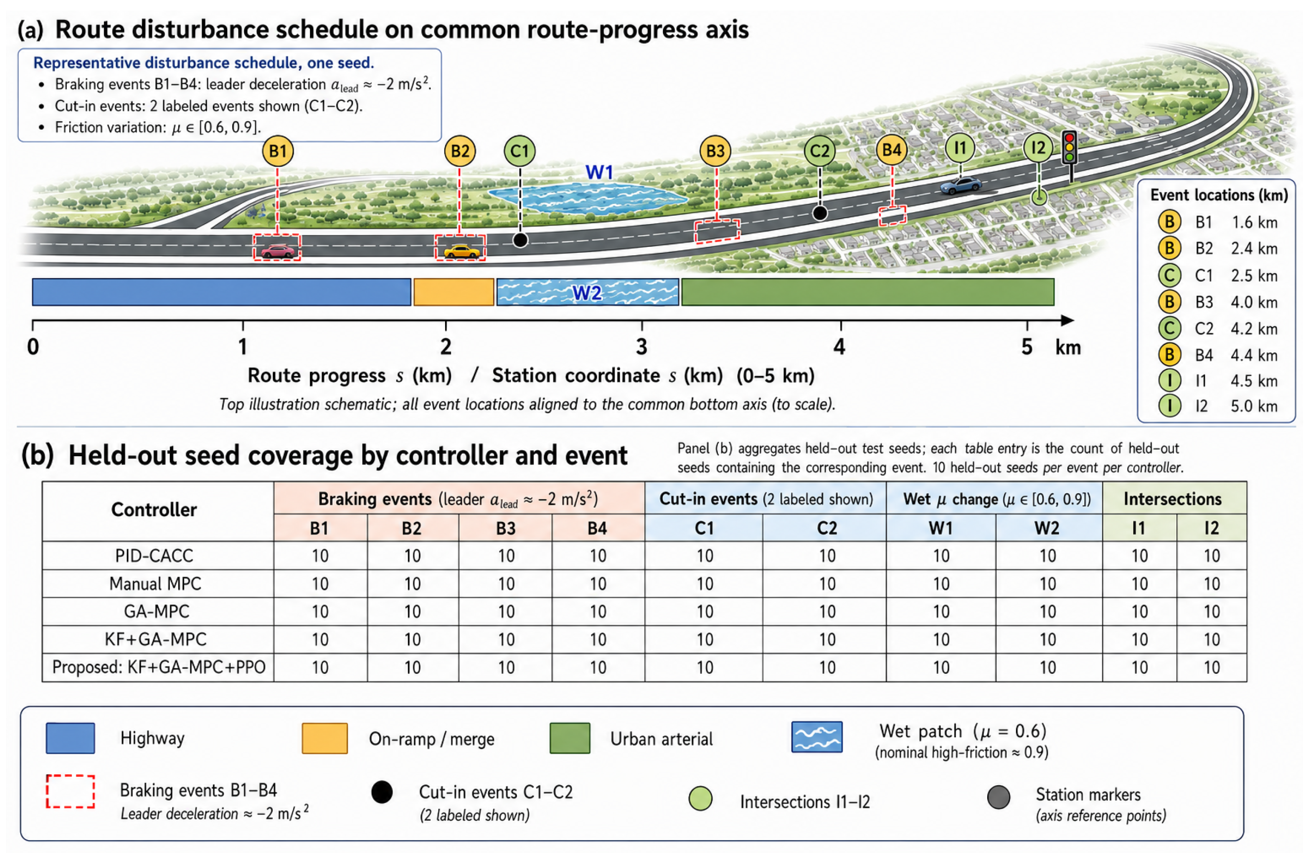
The evaluation combines CARLA simulation [53] with ECU HIL execution. CARLA supplies the road, traffic actors, disturbance schedule, road-surface annotation, and vehicle states transmitted to the ECU. The ECU executes the multi-rate controller and returns acceleration commands to the simulator. The 5 km route contains a 3 km highway/on-ramp segment and a 2 km urban segment with intersections. Each run uses a six-vehicle platoon, approximately eight random cut-in/cut-out maneuvers, four leader hard-braking events up to m/s2, and road-friction patches with . The software stack used CARLA (https://carla.org/, accessed on 12 May 2026), ROS 2 (https://docs.ros.org/, accessed on 12 May 2026), AUTOSAR (https://www.autosar.org/, accessed on 12 May 2026), Python (https://www.python.org/, accessed on 12 May 2026), and SciPy (https://scipy.org/, accessed on 12 May 2026); exact version identifiers were unavailable, so website/access-date information is provided. Figure 3 and Figure 4 show the route layout, disturbance schedule, and held-out seed coverage.
Figure 3.
CARLA evaluation route and spatial disturbance layout. The route spans a 5 km mixed corridor consisting of a highway segment, an on-ramp/merge section, and an urban arterial segment. Cut-in event locations, hard-braking zones, wet low-friction patches, and dry/high-friction regions are marked on the route schematic. The bottom station-coordinate axis provides the quantitative route scale from to 5 km; the upper route illustration is schematic and not drawn to scale. Wet patches correspond to low-friction regions with , while dry/nominal segments correspond to higher-friction operation, approximately .
Figure 4.
Route disturbance schedule and held-out seed coverage. (a) Representative disturbance schedule shown on a common route-progress axis, where all event locations are aligned to the station coordinate s over the 0–5 km route. Braking events B1–B4 correspond to leader deceleration disturbances of approximately ; C1–C2 denote the two labeled cut-in events; W1–W2 denote wet/friction-change regions; and I1–I2 denote urban intersection events. The friction range over the route is . (b) Held-out seed coverage by controller and event. Each entry denotes the number of held-out test seeds containing the corresponding event for the specified controller. Panel (a) is a representative one-seed schedule, while panel (b) aggregates held-out test seed coverage.
5.1. Signals, Assumptions, and Seed Split
Table 6 clarifies which signals are idealized in this CARLA/HIL study. Training, validation, and test seeds are separated before controller selection. The reported values use held-out seeds (15–24); no reward weights, MPC parameters, or policy checkpoints are selected using these test outcomes.
Table 6.
Controller input signals and observability assumptions in the HIL experiments.
5.2. Metrics
Spacing error is . Let denote the number of controlled followers and L the route length. The reported mean positive spacing-error exposure is
which has units of meters. We also compute a route-normalized positive-spacing exposure,
which has units of seconds and is used only as a spacing-exposure diagnostic, not as an energy metric. String stability is evaluated with the spacing-error variance ratio and diagnostic frequency-domain gains. For vehicle i, the distance-normalized positive tractive-energy-at-the-wheels proxy is
with the per-vehicle platoon mean for vehicles. Values are converted to kWh/km in the tables. The road-load force is
The nominal parameters are listed in Table 7. This proxy ranks controllers under a common road-load model and is not a calibrated fuel or battery-energy estimate.
Table 7.
Nominal road-load parameters used in the tractive-energy proxy.
Safety metrics use the clearance margin above the hard minimum, , and TTC-surrogate definitions
Control smoothness is measured using acceleration standard deviation, jerk, and peak cut-in deceleration. ECU timing is measured by timestamping each 50 Hz callback from message latch through command publication; we report mean latency, 99th percentile latency, jitter, and deadline-miss rate. Table 8 reports the corresponding safety KPIs across the held-out test seeds.
Table 8.
Safety KPIs across controllers on the held-out test seeds (, seeds 15–24). Values are mean ± std; is the minimum margin above , not the absolute bumper gap. Shield projection applies only to shielded variants.
6. Results
We first present high-level outcomes and then delve into specific metrics.
Unless otherwise stated, all quantitative KPIs in this section are aggregated across the five followers and then averaged over the held-out test set (Section 5). For the energy-proxy totals reported below, we additionally report the sum across all six vehicles to provide a fleet-level proxy.
6.1. Comparison Summary
Table 9 summarizes key metrics across controllers (including the selected time headway), showcasing the improvements of our proposed method:
Table 9.
Performance comparison summary (seed-averaged means over ; dispersion is reported in detailed KPI tables/figures).
6.2. Interpretation Under Common Random Numbers
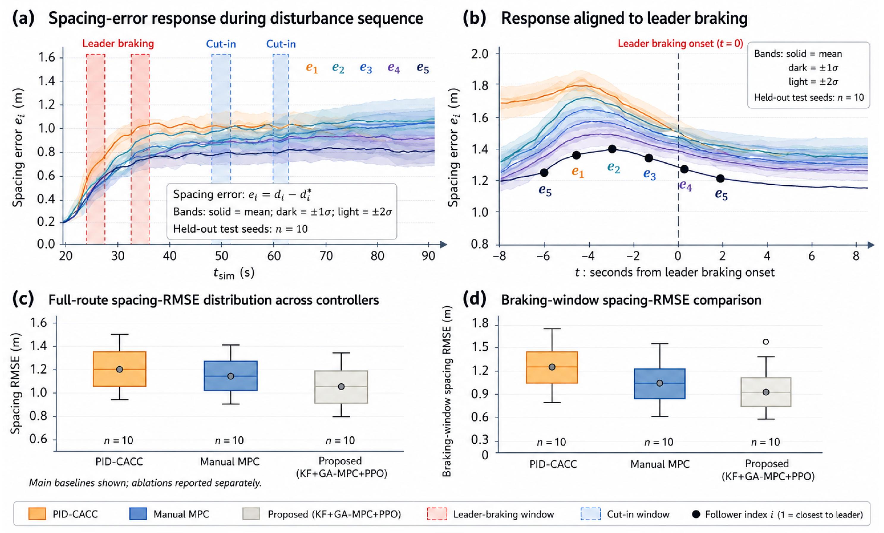
Each controller is evaluated on the same fixed held-out seed set (Section 5), so the principal controller comparisons are paired by construction. Accordingly, we interpret the evidence using the combination of seed-averaged summary tables and the run-level distributions in Figure 5, Figure 6 and Figure 7, rather than relying on a single headline mean. The qualitative ordering is consistent across these views: the proposed stack improves transient tracking and the tractive-energy proxy relative to Manual MPC while preserving the hard-safety margins reported in Table 8.
Figure 5.
Spacing-error response and RMSE comparison over held-out evaluation seeds. The spacing error is defined as , where is the realized inter-vehicle gap and is the desired time-headway gap. (a) Follower-level spacing-error response during a representative disturbance sequence for the proposed controller. Leader-braking and cut-in windows are marked by shaded vertical regions. (b) Event-aligned response relative to leader-braking onset, showing the mean response and uncertainty bands across held-out test seeds. Solid curves denote the mean, darker shaded bands denote , and lighter outer bands denote . (c) Full-route spacing-RMSE distribution across the main controller baselines. (d) Braking-window spacing-RMSE comparison. Panels (a,b) emphasize downstream follower propagation for the proposed controller, while panels (c,d) summarize controller-level distributions over held-out test seeds. Ablation results are reported separately.
Figure 6.
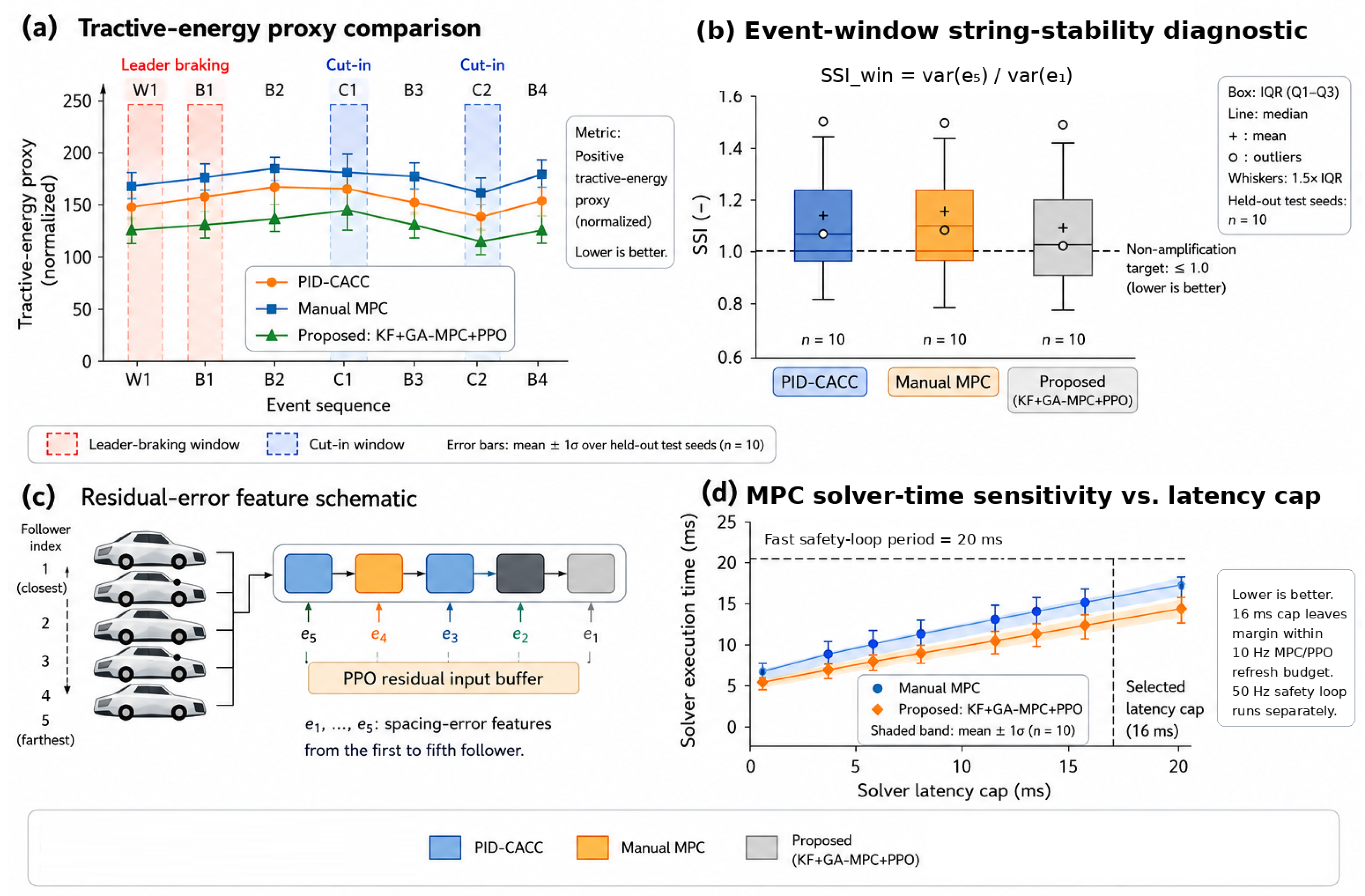
Route-level performance, event-window string-stability diagnostics, feature schematic, and timing summaries for the held-out evaluation runs. (a) Positive tractive-energy proxy across the event sequence; markers denote the mean and error bars denote over held-out seeds. Leader-braking and cut-in windows are highlighted by red and blue dashed boxes, respectively. (b) Event-window string-stability diagnostic computed over selected disturbance windows; values below one indicate non-amplifying downstream error propagation within the local window. Route-level SSI values used for the headline comparison are reported separately in Table 9. (c) Schematic of the residual-policy spacing-error input buffer, using follower spacing-error features . (d) MPC solver-time sensitivity versus latency cap. The selected solver cap is marked at 16 ms; MPC/PPO commands are refreshed at 10 Hz, while the 50 Hz safety loop runs separately.
Figure 7.
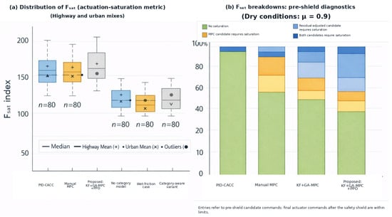
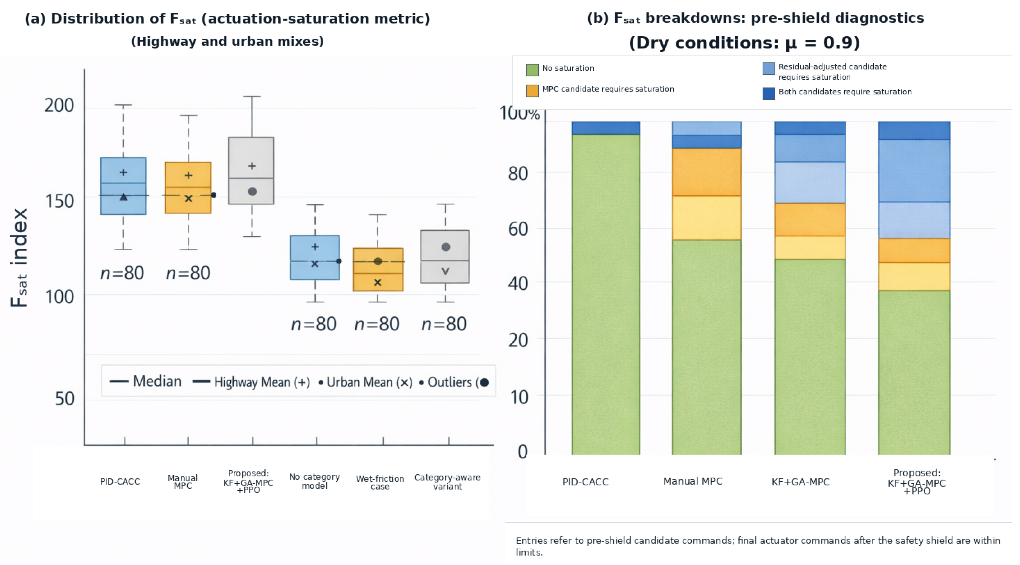
Saturation and pre-shield feasibility diagnostics. (a) Distribution of the actuation-saturation index over highway and urban mixtures, with boxplots summarizing the run-level distributions. Median lines, highway means, urban means, and outliers are indicated in the legend; where two yellow tones appear, the legend distinguishes the corresponding highway and urban summary markers. (b) Pre-shield candidate-command breakdown under dry conditions with . Stacked bars classify whether the nominal MPC candidate, the residual-adjusted candidate, both candidates, or neither candidate require saturation before safety projection. Entries refer to pre-shield candidate commands; final actuator commands after the safety shield remain within the admissible limits.
6.3. Headline Findings
Across the 10 held-out disturbance seeds, the proposed controller reduces the downstream spacing-error peak from 0.6 m (Manual MPC) to 0.4 m, reduces the string-stability variance ratio from 1.10 to 0.78, and reduces the route-normalized positive tractive-energy proxy from 0.110 to 0.097 kWh/km. At the same time, the constraint-aware controllers record zero collisions and zero measured distance/TTC-surrogate violations in Table 8. These values are the specific data basis for the conclusions drawn in Section 8.
6.4. Incremental Role and Interpretability of the PPO Residual
Residual-Policy Role
The learned policy is not a second primary controller. The carefully tuned MPC-only comparator in our ablation set is the GA+KF variant, which keeps the GA/NSGA-II-tuned MPC and friction-aware constraint tightening but removes the PPO residual. Comparing GA+KF with the full proposed KF+GA-MPC+PPO stack therefore isolates the added value of learning more directly than comparing only against Manual MPC.
The observed contribution of the residual is transient and regime-dependent. During leader braking, the residual typically biases the command toward slightly earlier deceleration or reduced propulsion, which creates a small temporary positive spacing error and reduces downstream amplification. During cut-ins, the intruder-distance feature allows the residual to reduce the tendency to wait until the gap has already collapsed; this reduces peak cut-in braking and the subsequent acceleration needed to close the gap. During steady cruising, the residual is small and the MPC dominates. This behavior is consistent with Table 9 and Figure 5; the dedicated quantitative ablation metrics are reported later in the ablation-study subsection. The proposed KF+GA-MPC+PPO stack has lower peak cut-in deceleration, lower acceleration standard deviation, and lower energy-proxy values than the MPC-only baselines, while Table 8 shows that the safety margins are not degraded.
The residual is also interpretable at the signal level. For each evaluation, run we retain the tuple at the 10 Hz refresh and the applied command at the 50 Hz actuator tick. Thus, the learned policy can be inspected by event window: negative before a cut-in indicates anticipatory easing; negative during leader braking indicates extra damping; positive after the disturbance indicates controlled recovery. Importantly, the shield-projection log verifies whether the residual approaches the admissible-set boundary. On the held-out tests the projection fraction remains near zero for the tuned proposed KF+GA-MPC+PPO stack (Table 8), which indicates that the learned residual improves behavior mainly inside the MPC-feasible region rather than by relying on frequent safety-filter intervention.
6.5. Overview of Platoon Behavior
Figure 5 summarizes spacing-error trajectories for the five followers under leader braking, aggregated over the held-out test seeds (mean ± std).
The key insight is that the combination of MPC and RL (with string stability constraints and learned behavior) prevents the accordion effect. The learned residual tends to create a small transient positive spacing error (i.e., slightly larger realized gaps than ) around sharp leader decelerations, which gives downstream vehicles additional braking margin without permanently increasing the nominal headway.
We also observed that during cut-in events, the RL-enhanced controller reacted more gracefully. For example, when a cut-in occurred between and , the baseline controllers often responded late, causing to brake hard and then accelerate to close the gap after the cut-in left. Our controller, thanks to the intruder-distance feature and the RL residual policy, would slightly adjust speed earlier, allowing the cut-in to merge with less disturbance.
Across the held-out seeds, route completion times are similar across controllers, indicating that the proposed controller does not trade substantial travel-time delay for improved safety margins during sharp transients.
Next, we quantify energy consumption differences.
6.6. Tractive-Energy Proxy
Figure 6a and Table 10 compare the route-normalized tractive-energy proxy (Section 5) of the platoon under each controller (average over 10 runs). Our approach yields the lowest proxy values, about 12% lower than Manual MPC and up to 18% lower than PID-CACC under the proxy definition used. Because PID-CACC can terminate early due to collisions in this stress suite (Table 8), we treat the PID-CACC energy number as a coarse reference; the collision-free comparisons are the primary basis for efficiency claims. Because the metric is a wheel-energy proxy (positive tractive energy), we interpret these results as improved longitudinal smoothness/reduced positive tractive effort, rather than calibrated fuel savings.
Table 10.
Distance-normalized positive tractive-energy proxy (kWh/km; Equation (20)) for the 5 km route, reported per vehicle and summed over the full six-vehicle platoon. Values are means over held-out seeds. This is an energy-at-the-wheels effort proxy, not a calibrated fuel or battery-energy model.
One observation in low-friction segments is that baseline controllers may induce more frequent brake–accelerate cycling after disturbances, increasing positive tractive effort when re-closing gaps. Our KF tightens feasible braking/traction limits and, together with MPC/RL, reduces aggressive oscillations, which is reflected in the proxy distributions.
Distributional Energy-Proxy Behavior
In addition to the route-normalized aggregate proxy values reported in Table 10, we inspected the run-level distributions of the instantaneous tractive-power proxy and the per-vehicle proxy totals. The proposed controller reduces high-demand transients and yields consistently lower proxy usage across the platoon, with the largest improvements typically observed for downstream vehicles.
6.7. Safety and Constraint Compliance
- Interpretation note. The PID-CACC baseline does not include explicit state/input constraints or a safety filter; under the disturbance suite it can violate the minimum-gap requirement and collide (Table 8). We therefore include PID-CACC safety KPIs primarily as a reference for non-constraint-aware CACC behavior and focus the fine-grained safety-margin comparison among the constraint-aware MPC/shielded variants.
Figure 7 analyzes saturation and feasibility behavior using , decomposing whether limitations arise from friction/actuation regulation versus MPC/RL proposal violations.
6.8. Safety Events and KPI Exceedances
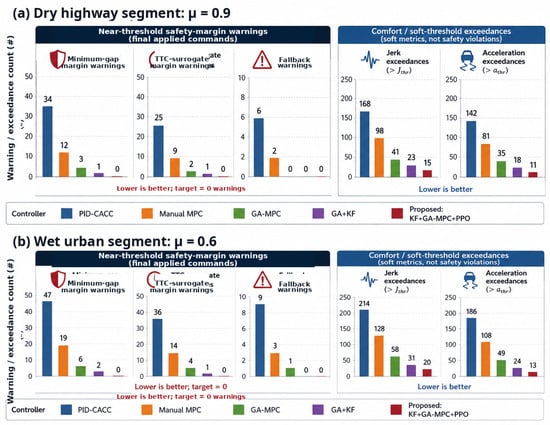
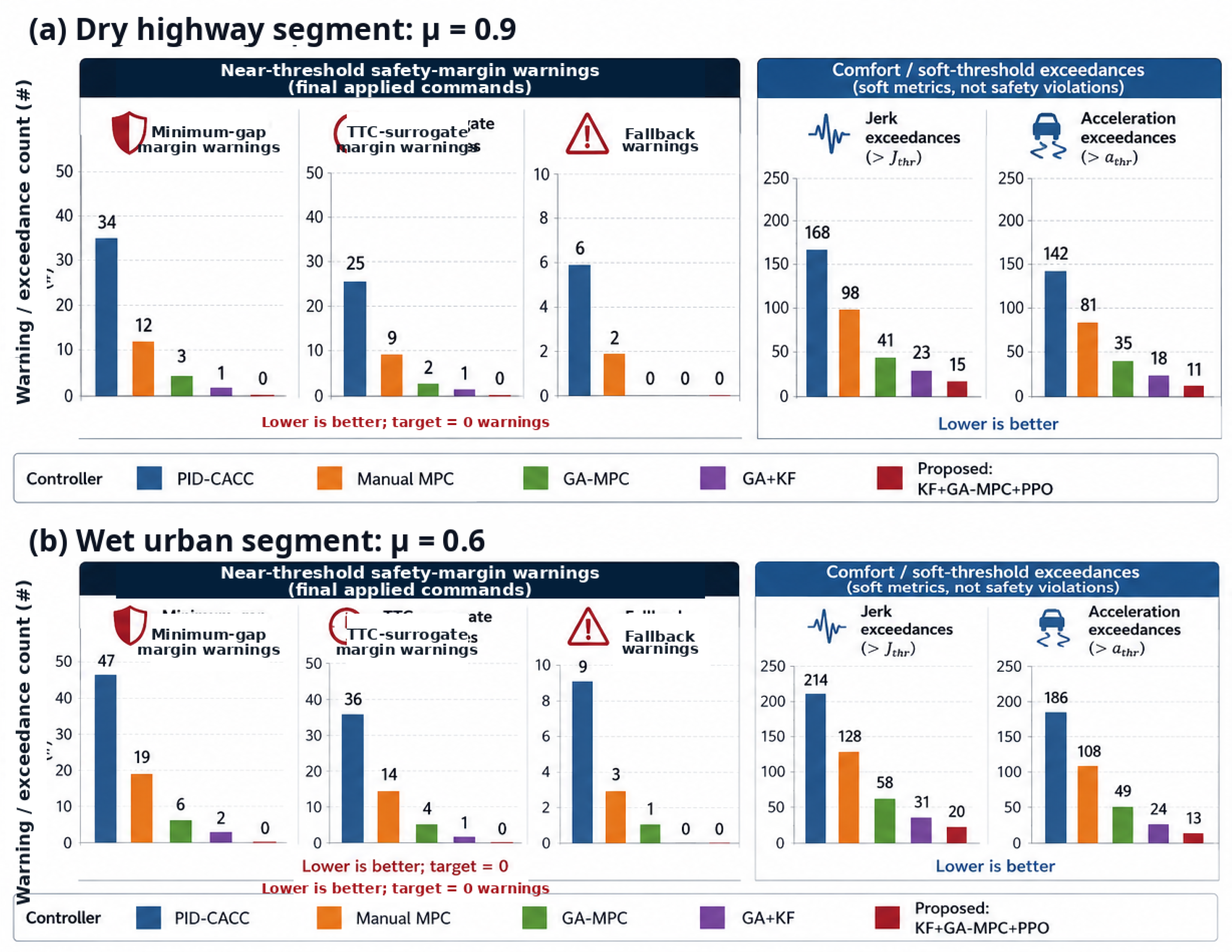
Figure 8 reports friction-regime-specific warning and comfort-exceedance counts, separating near-threshold safety-margin warnings from comfort-related soft-threshold diagnostics.
Figure 8.
Friction-regime-specific warning and comfort-exceedance counts over the held-out evaluation runs. (a) Dry highway segment with . (b) Wet urban segment with . (Left) panels report near-threshold safety-margin warnings under the final applied commands, including minimum-gap-margin, TTC-surrogate-margin, and fallback-warning counts. These warning counts are diagnostic indicators of proximity to the safety boundary and are distinct from the formal distance/TTC violations reported in Table 8. (Right) panels report comfort-related soft-threshold exceedances for jerk and acceleration; these are diagnostic smoothness metrics and are not safety violations. The symbol “#” denotes the count of warning/exceedance events; lower counts are better.
6.9. Robustness Across Regimes
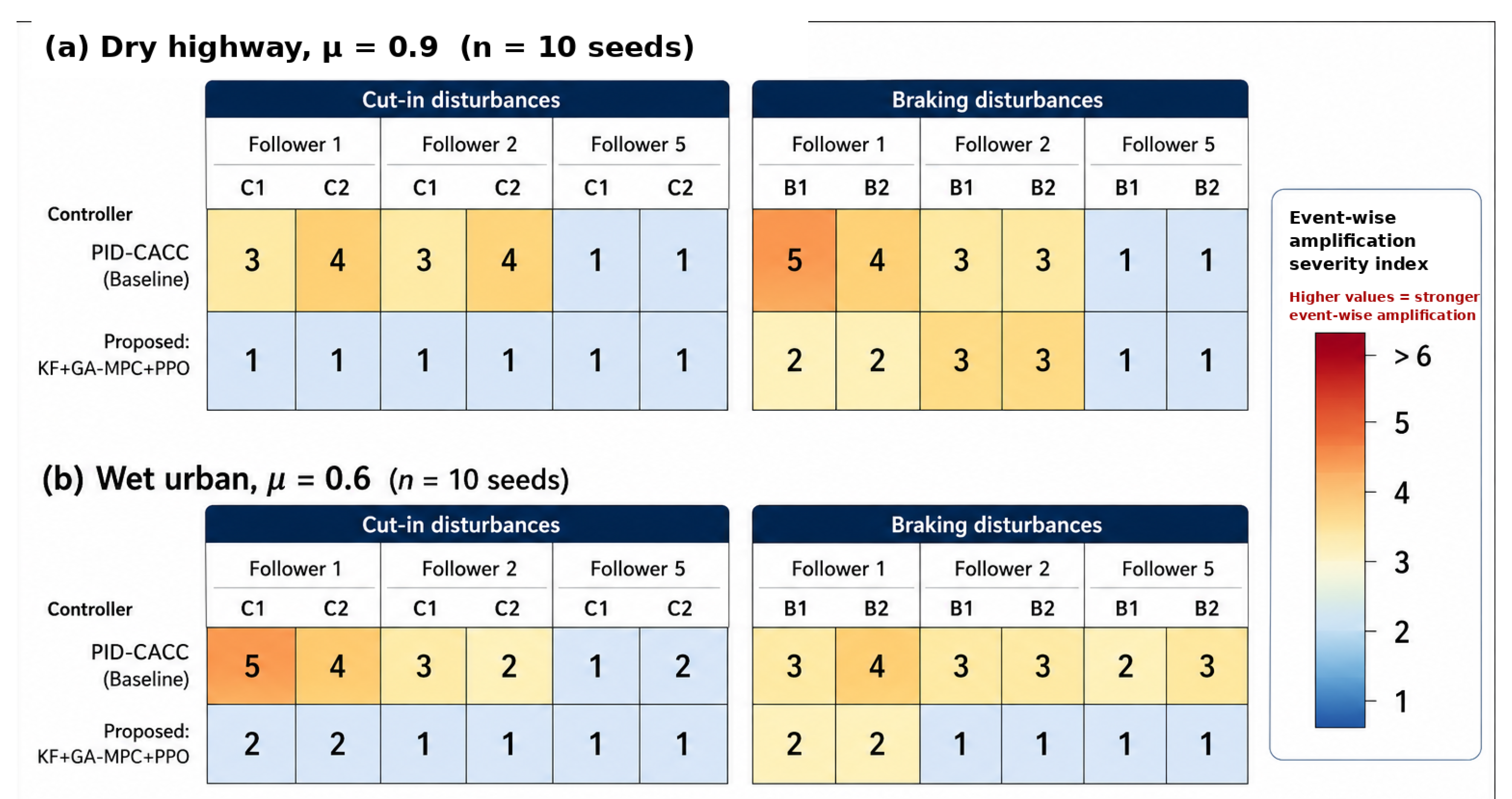
Figure 9 summarizes robustness over friction and disturbance intensity; qualitative CARLA snapshots illustrate matched operating conditions for the same regimes.
Figure 9.
Event-wise disturbance-amplification diagnostic for selected followers over the held-out evaluation seeds. (a) Dry highway segment with . (b) Wet urban segment with . Cells report an event-wise amplification severity index for two cut-in windows (C1–C2) and two braking windows (B1–B2), evaluated for Followers 1, 2, and 5. Lower values indicate weaker downstream amplification, whereas higher values indicate stronger event-wise amplification. The heatmap is used as a diagnostic comparison between PID-CACC and the proposed KF+GA-MPC+PPO controller; formal string-stability metrics are reported separately.
6.10. String Stability Metrics
To complement the time-domain string-stability index reported elsewhere in this section, we also estimate a frequency-domain disturbance gain from the leader’s longitudinal velocity to each follower’s longitudinal velocity. For each run and follower i, we form de-meaned signals (leader) and (follower), sampled at 50 Hz. We then compute a nonparametric frequency response estimate using Welch’s method: we estimate the cross power spectral density and the auto power spectral density (Hann window, 50% overlap; default window length 512 samples), and define the FRF magnitude
We evaluate the non-amplification condition over the band Hz, which captures the dominant braking/cut-in transients in our disturbance suite. Across seeds, we summarize each controller by the median and interquartile range of the per-run peak gain for each follower.
Consistent with the time-domain variance-ratio index, the PID-CACC baseline exhibits downstream amplification (peak gains exceeding unity for the last vehicles), while the proposed controller maintains peak gains at or below unity across the band for all followers under the tested scenarios, indicating string-stable disturbance attenuation.
6.11. Spacing and Headway Regulation
We define steady-state spacing error as the residual tracking error to the constant-time-gap policy during constant-speed cruising (excluding disturbance windows). Across controllers, the residual bias remains small (within m): PID-CACC achieves near-zero bias due to integral action, while MPC-based controllers achieve comparable bias through explicit reference tracking; the bounded residual policy does not introduce a systematic offset.
6.12. Cut-In Handling
We analyzed a representative highway cut-in event in which a non-platoon vehicle inserted between and while the platoon was cruising at 100 km/h. This maneuver produces an abrupt reduction in the available gap for and can trigger large transient braking and disturbance amplification if not handled carefully.
In our stack, cut-in robustness is achieved by coupling (i) friction-adaptive actuation bounds (15b) so that commanded longitudinal forces remain feasible on low- patches, (ii) a relative-acceleration mismatch constraint (15e) that suppresses aggressive follower–predecessor acceleration differences, and (iii) the command-level safety shield (3) and (4) that projects the combined MPC + RL command onto the safe set when the raw proposal would violate hard constraints.
For evaluation, we focus on transient safety and recovery, reporting (a) minimum realized gap, (b) minimum time-to-collision (TTC) surrogate, (c) peak deceleration magnitude, and (d) the time to return within a tolerance band around the desired headway after the intruder has merged. These quantities complement the steady-state and string-stability metrics reported elsewhere in this section.
6.13. Control Effort and Comfort
We computed the standard deviation of acceleration, which we use as a compact measure of ride oscillation. For , the worst-case vehicle, we obtained:
- PID-CACC: over the run.
- Manual MPC: .
- Proposed: KF+GA-MPC+PPO: .
6.14. Computational Performance and Latency
6.14.1. What Is Measured (And Where)
All latency/jitter values in this subsection are wall-clock measurements on the ECU using a monotonic timer, per the definitions in Section 5. Specifically, the reported loop latency is measured from entry of the 50 Hz control callback to completion of actuation-command publication. These values therefore capture ECU-side computation (KF update, command fusion, and any 10 Hz refresh work that coincides with the tick) plus ROS 2 executor overhead, but exclude simulator and network delay.
6.14.2. Results and Deadline Compliance
Figure 6d summarizes the ECU execution-time/latency-budget relationship for the proposed RL-enhanced MPC controller at 50 Hz. Over the trace, the mean loop latency is ms with execution-time jitter (standard deviation) ms, and the maximum observed loop latency is ms, all below the 20 ms real-time deadline implied by the 50 Hz control period. This leaves a measured worst-case fast-loop margin of ms. The MPC optimization and RL inference execute as separate 10 Hz tasks (Table 3) with a 100 ms period; thus their solve times are assessed against the 100 ms refresh budget, while reports the fast 50 Hz estimation/safety loop latency. The measured MPC worst case is 26.29 ms, leaving a 73.71 ms margin relative to the 10 Hz refresh period. We observed zero deadline misses (i.e., ms never occurred in the logged runs). Table 11 summarizes these timing statistics and explicitly reports the margins.
Table 11.
HIL real-time statistics for ECU timing. ECU loop latency and jitter are measured on the ECU using monotonic wall-clock timestamps, .
6.15. Ablation Study
Table 12 supplements the safety KPIs in Table 8 with quantitative ablation metrics on the same held-out test seeds. The comparison isolates the effect of GA tuning, KF-based friction tightening, and the PPO residual while keeping the scenario generator, seed partition, and reporting protocol fixed.
Table 12.
Quantitative ablation summary on the held-out test seeds (). Tracking, string-stability, and energy-proxy values are seed-averaged means; safety margins are reported as mean ± std and correspond to the same definitions as Table 8. Lower values are better for , variance ratio, and ; higher values are better for and TTCmin.
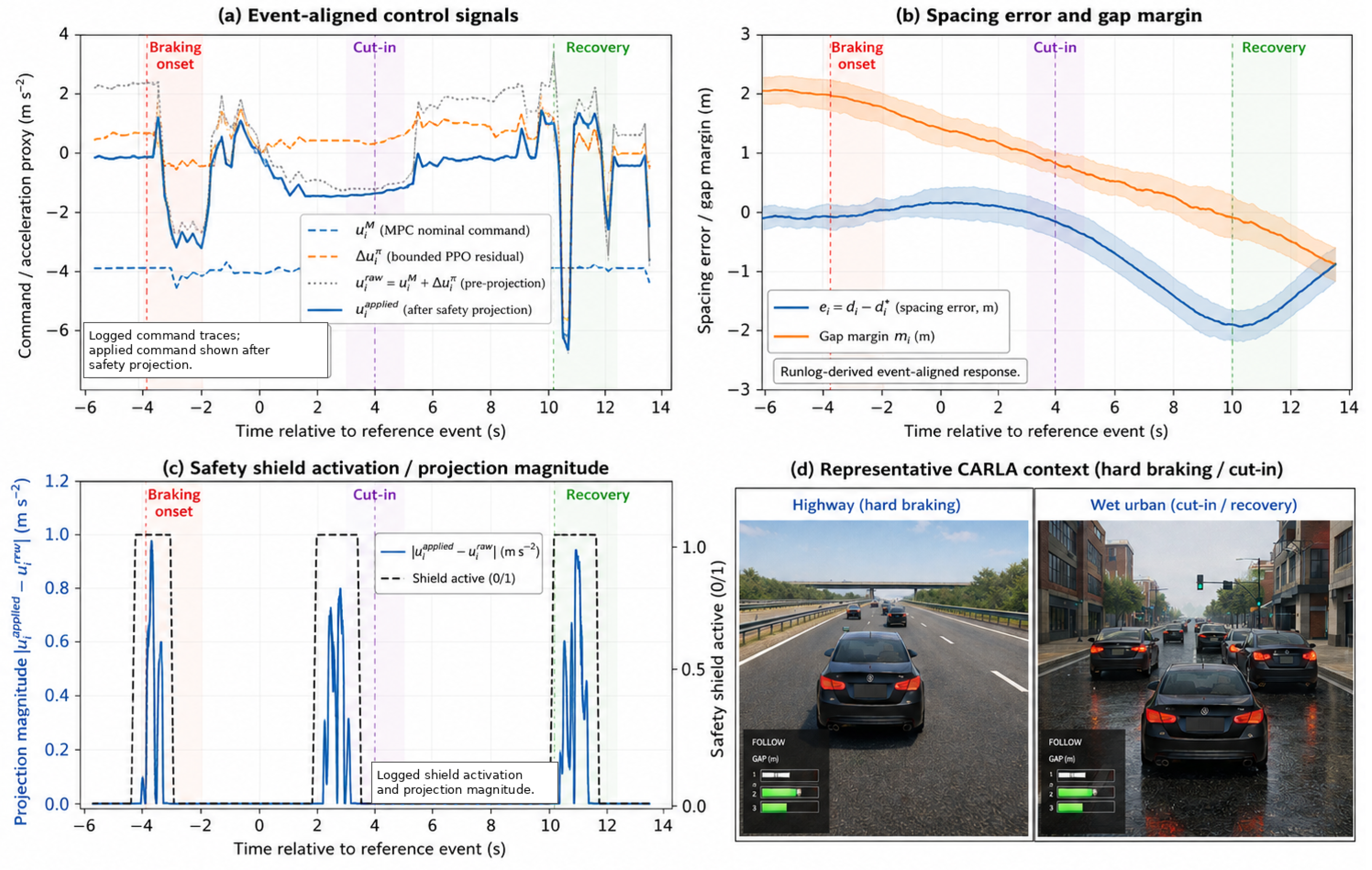
Figure 10 provides event-aligned logs for a representative held-out disturbance sequence, including command decomposition and safety-shield activity.
Figure 10.
Event-aligned logged behavior of the proposed KF+GA-MPC+PPO controller during a representative held-out disturbance sequence. (a) Command decomposition showing the MPC command , bounded PPO residual , raw command , and applied command . (b) Spacing response with and logged gap margin . (c) Safety-shield activity, reported by projection magnitude and the binary shield-active flag. (d) Representative CARLA context for the hard-braking, cut-in, and recovery intervals.
To isolate the contribution of each component, we evaluate ablations that remove one module at a time while holding the scenario generator, seed partition, and reporting protocol fixed. The ablation variants correspond to the standardized nomenclature used throughout the paper: Naive MPC weights, GA-MPC, GA+KF, and proposed KF+GA-MPC+PPO. In summary, removing the PPO residual policy increases the route-normalized tractive-energy proxy and slightly worsens spacing tracking, while removing friction estimation degrades robustness in low- segments due to mismatched actuation limits. Finally, omitting GA-based tuning yields an MPC configuration that can violate string-stability criteria (variance ratio and frequency-domain gain exceeding unity).
- Without PPO residual (GA+KF only): Energy-proxy and spacing metrics degrade modestly relative to the proposed KF+GA-MPC+PPO stack, consistent with the role of the bounded residual in damping post-disturbance oscillations.
- Without KF (GA-MPC with fixed limits): In low-friction segments, the controller becomes either overly aggressive or overly conservative depending on the assumed , leading to larger tracking transients and increased reliance on conservative margins.
- Without GA tuning (naive MPC weights): The resulting controller exhibits poorer disturbance attenuation and can become string unstable under the disturbance suite.
7. Discussion
The results suggest that combining model-based structure (explicit dynamics, constraints, and receding-horizon optimization) with learning components can improve platoon performance under mixed disturbances, while preserving a safety-oriented execution stack suitable for embedded deployment. This section summarizes practical implications and clarifies what the experiments do and do not establish.
7.1. Robustness and Adaptability
Two mechanisms drive robustness in our experiments: (i) constraint-aware planning via MPC (including friction-tightened actuation bounds), and (ii) data-driven residual shaping via PPO. The MPC layer provides a transparent place to encode hard constraints (minimum clearance, TTC surrogates, and actuation limits) and to regularize aggressiveness. The KF provides a simple way to inject friction information into the constraint set rather than relying on the controller to infer friction implicitly from tracking error. In this work, friction observations are derived from simulator road-surface annotations before filtering; in deployment they would have to come from slip-/model-based estimators or sensor-fusion pipelines built from onboard signals rather than map labels. We therefore treat the current module as a friction-aware signal filter in simulation, not as a validated onboard friction estimator. Because is used primarily to tighten bounds, moderate estimation error tends to bias the controller toward conservatism rather than unsafe aggressiveness.
Across the held-out disturbance seeds, the proposed KF+GA-MPC+PPO stack reduces oscillatory brake–accelerate cycles after leader braking and cut-ins. We interpret this as improved damping of disturbance propagation rather than a change in the nominal spacing policy: headway parameters are fixed per controller, but the learned residual can temporarily bias longitudinal commands so that realized gaps become slightly larger than during sharp transients, providing additional braking margin before closing the gap again.
A complementary fairness view is to compare controllers at a matched time headway across methods. Because headway is part of each controller’s spacing policy and different controllers can have different best-operating points, we report each method at its validated operating point (Section 5 and Table 9). A headway-matched sweep would yield throughput–stability trade-off curves and is a useful complement for future work.
Finally, while we report safety events (collisions and constraint-infeasible fallbacks), the shield itself provides an additional diagnostic signal: the rate and magnitude of command projections. These can be logged to quantify how often the raw (MPC+RL) proposal approaches constraint boundaries and to localize which disturbance types drive interventions.
7.2. Energy-Proxy Behavior
The reported reductions refer to a tractive-energy-at-the-wheels proxy (Section 5), not a calibrated fuel or battery-energy model. Consequently, we interpret improvements conservatively: lower positive tractive energy indicates smoother longitudinal profiles and reduced re-acceleration after disturbances, which is directionally consistent with improved efficiency but does not, by itself, quantify fuel savings. A more direct validation would combine either (i) a calibrated powertrain/fuel model, or (ii) measured energy consumption in a real vehicle or high-fidelity powertrain co-simulation, while preserving the same disturbance generator and safety constraints.
7.3. Architecture Complexity and Control-Strategy Trade-Offs
The proposed architecture is intentionally more complex than PID/CACC, input shaping, or a single manually tuned MPC. The benefit of the added complexity is modular separation of responsibilities: MPC handles prediction and constraints; KF provides friction-dependent bound tightening; PPO contributes bounded transient refinement; and the shield enforces a fast command-level admissibility check. The cost is a larger validation burden, more software interfaces, and the need to log and test each module separately.
In applications where the disturbance spectrum is narrow and the dominant oscillation modes are well identified, low-complexity feedforward filters or input shapers can be attractive because they add little computation and are straightforward to certify. In the present platooning scenario, however, the main challenge is not a single fixed flexible mode; it is the simultaneous presence of hard clearance constraints, time-varying friction, cut-ins, and leader braking. For that reason, we view command shaping and feedforward filtering as complementary rather than competing replacements: they could smooth the reference or MPC command, while the constrained MPC and shield would still be required to enforce clearance and actuation limits. This discussion also clarifies the practical design trade-off: the proposed stack is justified when disturbance diversity and safety constraints dominate, whereas simpler command-shaping solutions may be preferable for systems with known oscillatory modes and less stringent state constraints.
7.4. Hardware-in-the-Loop and Deployment Considerations
The HIL experiments demonstrate that a multi-rate design can accommodate optimization and inference within realistic embedded timing. The 50 Hz tick (KF update and safety projection) isolates fast safety-critical enforcement from the slower 10 Hz MPC/RL refresh. Although our prototype MPC solver uses Python (https://www.python.org/, accessed on 12 May 2026) and SciPy (https://scipy.org/, accessed on 12 May 2026) on the ECU, the measured margins (Section 6) indicate that an embedded-focused QP solver (or code generation) could further reduce jitter and improve worst-case determinism. This suggests that the architecture is practical on contemporary embedded platforms, provided that solver and middleware choices are made with real-time determinism in mind.
7.5. Limitations and Future Work
This study is intentionally scoped to longitudinal platooning under a specific CARLA route and disturbance generator. The results are therefore a controlled HIL/simulation assessment of the proposed control stack, not a claim of field-ready autonomy. The following limitations are deployment-relevant rather than merely cosmetic:
- Lateral planning and cut-in origin: the controller does not plan lane changes, negotiate merges, or generate obstacle-avoidance trajectories. Cut-ins are exogenous disturbances, and the platoon responds only through longitudinal acceleration. Coupling this longitudinal controller to a validated lane-change planner and predictor, such as the hybrid path-planning family represented by [43], is a necessary step before multi-lane deployment.
- Sensing, association, and friction realism: most inputs are derived from CARLA kinematic states (idealized sensing), and friction is derived from road-surface annotations before filtering. A real vehicle would require perception-based lane association during cut-ins, robust object tracking, V2V dropout handling, and an onboard friction estimator grounded in measurable tire/vehicle responses. Candidate deployment routes include slip-ratio/longitudinal-force observers, wheel-speed and IMU fusion, tire model residuals, and map/weather priors. Estimation delay and bias would have to be propagated into the constraint-tightening margin; conservative lower-confidence bounds on are preferable to point estimates when safety is the priority. The tire-load and inflation sensitivity emphasized in [44] illustrate why simulator surface labels alone cannot validate friction estimation.
- Baseline comparability and headway: time headway h is tuned per controller within a shared discrete set. Although this reflects common practice (headway is part of the policy), headway-matched comparisons would further isolate control-law benefits and quantify throughput trade-offs.
- Model and actuation fidelity: we use a simplified longitudinal model and do not explicitly model drivetrain lag, brake dynamics, actuator saturation transients, road grade, or heterogeneous vehicle parameters. Robustness to vehicle heterogeneity, grades, and actuator delays should be quantified.
- Learning safety guarantees: the learned residual is empirically safe under the tested scenarios, but we do not provide formal guarantees of stability or constraint satisfaction for the learned component beyond the command-level safety filter. The shield provides an instantaneous admissibility contract when feasible, not an unbounded-horizon invariance proof.
- Energy and comfort metrics: the energy proxy is not a calibrated fuel model, and comfort is summarized via longitudinal acceleration and jerk. Future work should incorporate calibrated powertrain models (or measured consumption) and broader comfort metrics.
- System complexity: the hierarchical stack improves modularity and safety auditing but increases implementation complexity relative to PID, feedforward filters, or a single MPC. Deployment should therefore include module-level tests, interface-fault injection, logging of residual and shield activity, and fallback modes that degrade gracefully to MPC-only operation.
- Solver determinism and certification path: SLSQP provides a convenient prototype solver but is not a hard real-time QP solver. Production deployment should use an embedded solver, generated code, explicit middleware timing budgets, fault handling for infeasible states, and a safety-case argument consistent with automotive validation practice.
7.6. Generality of the Approach
Although we focus on platooning, the overall pipeline—online parameter tracking (KF), offline multi-objective weight selection (GA/NSGA-II), and a learned residual policy trained with a surrogate—is applicable to other constrained automotive control problems (e.g., eco-driving MPC, adaptive cruise control with heterogeneous traffic, or motion control with uncertain friction). The key architectural idea is to keep constraints and safety enforcement explicit while using learning primarily to refine performance in disturbance-rich regimes where hand-tuning becomes brittle. A similar separation between cooperative task behavior and local control has appeared in broader multi-agent autonomy contexts, including UAV swarm coordination, although the vehicle-platooning constraints considered here are different [54].
8. Conclusions
This paper presented a safety-filtered residual-learning architecture for longitudinal autonomous-vehicle platooning under hard braking, cut-ins, and varying road friction. The proposed stack keeps safety-critical structure explicit: a scalar KF supplies friction-dependent constraint tightening, a GA/NSGA-II-tuned MPC computes the conservative command, a bounded PPO residual improves transient behavior, and a 50 Hz command-level projection admits only commands inside the instantaneous admissible set when the projection problem is feasible.
The held-out CARLA/HIL evaluation shows that the full stack improves spacing regulation and the tractive-effort proxy relative to Manual MPC while retaining zero collisions, zero distance/TTC-surrogate violations, non-amplifying disturbance propagation, and zero 50 Hz deadline misses in the reported tests. The ablations indicate that GA tuning improves the MPC operating point, KF tightening increases robustness on low-friction patches, and the PPO residual mainly contributes during cut-in and post-braking recovery by reducing late braking and re-acceleration.
The conclusions are bounded by the stated assumptions: the study addresses longitudinal single-lane platooning; CARLA actor states provide the kinematic and cut-in features; the friction signal is simulator-annotation based; and the energy result is a tractive-effort proxy rather than a calibrated consumption model. Future work should replace the idealized signals with perception and onboard friction estimation, test packet loss and actuator delays, use deployment-grade embedded QP solvers, extend the architecture to multi-lane/lateral coordination, and validate larger heterogeneous platoons under broader traffic and weather conditions.
Author Contributions
Conceptualization, A.S.A., A.M.G. and A.A.-S.; methodology, all authors; software, A.S.A.; validation, all authors; formal analysis, all authors; investigation, all authors; data curation, A.S.A.; writing—original draft preparation, A.S.A.; writing—review and editing, all authors; supervision, A.M.G. and A.A.-S. All authors have read and agreed to the published version of the manuscript.
Funding
This research funding by Ongoing Research Funding program, (ORF-2026-1302), King Saud University, Riyadh, Saudi Arabia.
Data Availability Statement
The manuscript documents the train/validation/test seed split, principal controller hyperparameters, and KPI definitions used to produce the reported results. A structured reproducibility manifest accompanies this submission. Processed simulation outputs, controller configuration files, and post-processing scripts supporting the reported findings are available from the corresponding authors upon reasonable request for scholarly verification.
Conflicts of Interest
The authors declare no conflicts of interest.
References
- Mirwald, J.; Ultsch, J.; de Castro, R.; Brembeck, J. Learning-Based Cooperative Adaptive Cruise Control. Actuators 2021, 10, 286. [Google Scholar] [CrossRef] [Scilit]
- Turri, V.; Besselink, B.; Johansson, K.H. Cooperative Look-Ahead Control for Fuel-Efficient and Safe Heavy-Duty Vehicle Platooning. IEEE Trans. Control Syst. Technol. 2017, 25, 12–28. [Google Scholar] [CrossRef] [Scilit]
- Liu, T.; Meidani, H. Neural Network Surrogate Models for Aerodynamic Analysis in Truck Platoons: Implications on Autonomous Freight Delivery. Int. J. Transp. Sci. Technol. 2024, 16, 234–243. [Google Scholar] [CrossRef] [Scilit]
- van Arem, B.; van Driel, C.J.G.; Visser, R. The Impact of Cooperative Adaptive Cruise Control on Traffic-Flow Characteristics. IEEE Trans. Intell. Transp. Syst. 2006, 7, 429–436. [Google Scholar] [CrossRef] [Scilit]
- Guanetti, J.; Kim, Y.; Borrelli, F. Control of Connected and Automated Vehicles: State of the Art and Future Challenges. Annu. Rev. Control 2018, 45, 18–40. [Google Scholar] [CrossRef] [Scilit]
- Jia, D.; Lu, K.; Wang, J.; Zhang, X.; Shen, X. A Survey on Platoon-Based Vehicular Cyber-Physical Systems. IEEE Commun. Surv. Tutor. 2016, 18, 263–284. [Google Scholar] [CrossRef] [Scilit]
- Swaroop, D.; Hedrick, J.K. String Stability of Interconnected Systems. IEEE Trans. Autom. Control 1996, 41, 349–357. [Google Scholar] [CrossRef] [Scilit]
- Liang, C.Y.; Peng, H. String Stability Analysis of Adaptive Cruise Controlled Vehicles. JSME Int. J. Ser. C Mech. Syst. Mach. Elem. Manuf. 2000, 43, 671–677. [Google Scholar] [CrossRef] [Scilit]
- Gunter, G.; Janssen, C.; Barbour, W.; Stern, R.E.; Work, D.B. Model-Based String Stability of Adaptive Cruise Control Systems Using Field Data. IEEE Trans. Intell. Veh. 2020, 5, 90–99. [Google Scholar] [CrossRef] [Scilit]
- Rajamani, R.; Zhu, C.Y. Semi-Autonomous Adaptive Cruise Control Systems. IEEE Trans. Veh. Technol. 2002, 51, 1186–1192. [Google Scholar] [CrossRef] [Scilit]
- Seiler, P.; Pant, A.; Hedrick, J.K. Disturbance Propagation in Vehicle Strings. IEEE Trans. Autom. Control 2004, 49, 1835–1842. [Google Scholar] [CrossRef] [Scilit]
- Stankovic, S.S.; Stanojevic, M.J.; Siljak, D.D. Decentralized Overlapping Control of a Platoon of Vehicles. IEEE Trans. Control Syst. Technol. 2000, 8, 816–832. [Google Scholar] [CrossRef] [Scilit]
- Dunbar, W.B.; Caveney, D.S. Distributed Receding Horizon Control of Vehicle Platoons: Stability and String Stability. IEEE Trans. Autom. Control 2012, 57, 620–633. [Google Scholar] [CrossRef] [Scilit]
- Stenger, D.; Ritschel, R.; Krabbes, F.; Vosswinkel, R.; Richter, H. What Is the Best Way to Optimally Parameterize the MPC Cost Function for Vehicle Guidance? Mathematics 2023, 11, 465. [Google Scholar] [CrossRef] [Scilit]
- Feng, S.; Song, Z.; Li, Z.; Zhang, Y.; Li, L. Robust Platoon Control in Mixed Traffic Flow Based on Tube Model Predictive Control. IEEE Trans. Intell. Veh. 2021, 6, 711–722. [Google Scholar] [CrossRef] [Scilit]
- Wang, P.; Deng, H.; Zhang, J.; Wang, L.; Zhang, M.; Li, Y. Model Predictive Control for Connected Vehicle Platoon Under Switching Communication Topology. IEEE Trans. Intell. Transp. Syst. 2022, 23, 7817–7830. [Google Scholar] [CrossRef] [Scilit]
- Lan, J.; Zhao, D.; Tian, D. Data-Driven Robust Predictive Control for Mixed Vehicle Platoons Using Noisy Measurement. IEEE Trans. Intell. Transp. Syst. 2023, 24, 6586–6596. [Google Scholar] [CrossRef] [Scilit]
- Ploeg, J.; Scheepers, B.T.M.; van Nunen, E.; van de Wouw, N.; Nijmeijer, H. Design and Experimental Evaluation of Cooperative Adaptive Cruise Control. In Proceedings of the 14th IEEE International Intelligent Transportation Systems Conference (ITSC), Washington, DC, USA, 5–7 October 2011; pp. 260–265. [Google Scholar] [CrossRef] [Scilit]
- Xing, H.; Ploeg, J.; Nijmeijer, H. Compensation of Communication Delays in a Cooperative ACC System. IEEE Trans. Veh. Technol. 2020, 69, 1177–1189. [Google Scholar] [CrossRef]
- Song, X.; Chen, L.; Wang, K.; He, D. Robust Time-Delay Feedback Control of Vehicular CACC Systems with Uncertain Dynamics. Sensors 2020, 20, 1775. [Google Scholar] [CrossRef] [Scilit]
- Patel, C.; Harri, J.; Bonnet, C. Centralized Model Predictive CACC Control Robust to Burst Communication Errors. In Proceedings of the 88th IEEE Vehicular Technology Conference (VTC-Fall), Chicago, IL, USA, 27–30 August 2018; pp. 1–7. [Google Scholar] [CrossRef] [Scilit]
- Gao, F.; Li, S.E.; Zheng, Y.; Kum, D. Robust Control of Heterogeneous Vehicular Platoon with Uncertain Dynamics and Communication Delay. IET Intell. Transp. Syst. 2016, 10, 503–513. [Google Scholar] [CrossRef] [Scilit]
- Wu, C.; Lin, Y.; Eskandarian, A. Cooperative Adaptive Cruise Control with Adaptive Kalman Filter Subject to Temporary Communication Loss. IEEE Access 2019, 7, 93558–93568. [Google Scholar] [CrossRef] [Scilit]
- Li, S.; Chen, C.; Zheng, H.; Wang, J.; Xu, Q.; Wang, J.; Li, K. Mixed Platoon Control under Noise and Attacks. arXiv 2024. [Google Scholar] [CrossRef] [Scilit]
- Hu, M.; Li, C.; Bian, Y.; Zhang, H.; Qin, Z.; Xu, B. Fuel-Economy-Oriented Vehicle Platoon Control Using Economic Model Predictive Control. IEEE Trans. Intell. Transp. Syst. 2022, 23, 20836–20849. [Google Scholar] [CrossRef] [Scilit]
- Jin, L.; Qiu, N.; Tian, D.; Zhang, Q.; Teng, F.; Jin, B.; Xiao, F. MPC-Based Path Tracking Strategy for 4WID&4WIS Vehicles Using B-Spline Approximation and State-Dependent Reference. Control Eng. Pract. 2025, 165, 106546. [Google Scholar] [CrossRef] [Scilit]
- Ackermann, J. Robust Control: The Parameter Space Approach, 2nd ed.; Springer: London, UK, 2002. [Google Scholar] [CrossRef] [Scilit]
- Deb, K.; Pratap, A.; Agarwal, S.; Meyarivan, T. A Fast and Elitist Multiobjective Genetic Algorithm: NSGA-II. IEEE Trans. Evol. Comput. 2002, 6, 182–197. [Google Scholar] [CrossRef] [Scilit]
- Prastiyanto, D.; Apriaskar, E.; Ibrahim, R.F.; Rumanda, A.; Manaf, A.A.; Amelia, I. Adaptive Cruise Control Tuned by Genetic Algorithm for Safe Distance of Automated Vehicle. IOP Conf. Ser. Earth Environ. Sci. 2023, 1203, 012026. [Google Scholar] [CrossRef] [Scilit]
- Sorourifar, F.; Makrygirgos, G.; Mesbah, A.; Paulson, J.A. A Data-Driven Automatic Tuning Method for MPC under Uncertainty Using Constrained Bayesian Optimization. IFAC-PapersOnLine 2021, 54, 243–250. [Google Scholar] [CrossRef] [Scilit]
- Lin, Y.; McPhee, J.; Azad, N.L. Comparison of Deep Reinforcement Learning and Model Predictive Control for Adaptive Cruise Control. IEEE Trans. Intell. Veh. 2021, 6, 221–231. [Google Scholar] [CrossRef] [Scilit]
- Liu, T.; Lei, L.; Zheng, K.; Zhang, K. Autonomous Platoon Control with Integrated Deep Reinforcement Learning and Dynamic Programming. IEEE Internet Things J. 2023, 10, 5476–5489. [Google Scholar] [CrossRef] [Scilit]
- Peake, A.; McCalmon, J.; Raiford, B.; Liu, T.; Alqahtani, S. Multi-Agent Reinforcement Learning for Cooperative Adaptive Cruise Control. In Proceedings of the 32nd IEEE International Conference on Tools with Artificial Intelligence (ICTAI), Baltimore, MD, USA, 9–11 November 2020; pp. 15–22. [Google Scholar] [CrossRef] [Scilit]
- Chen, J.; Zhou, Z.; Duan, Y.; Yu, B. Research on Reinforcement-Learning-Based Truck Platooning Control Strategies in Highway On-Ramp Regions. World Electr. Veh. J. 2023, 14, 273. [Google Scholar] [CrossRef] [Scilit]
- Wei, S.; Zou, Y.; Zhang, T.; Zhang, X.; Wang, W. Design and Experimental Validation of a Cooperative Adaptive Cruise Control System Based on Supervised Reinforcement Learning. Appl. Sci. 2018, 8, 1014. [Google Scholar] [CrossRef] [Scilit]
- Li, M.; Cao, Z.J.; Li, Z. A Reinforcement Learning-Based Vehicle Platoon Control Strategy for Reducing Energy Consumption in Traffic Oscillations. IEEE Trans. Neural Netw. Learn. Syst. 2021, 32, 5309–5322. [Google Scholar] [CrossRef] [Scilit]
- Zou, Y.; Jin, L.; Xiong, X. Dyna-Style Learning with a Macroscopic Model for Vehicle Platooning in Mixed-Autonomy Traffic. arXiv 2024. [Google Scholar] [CrossRef] [Scilit]
- Zhang, Q.; Xing, Y.; Wang, J.; Fang, Z.; Liu, Y.; Yin, G. Interaction-Aware and Driving Style-Aware Trajectory Prediction for Heterogeneous Vehicles in Mixed Traffic Environment. IEEE Trans. Intell. Transp. Syst. 2025, 26, 10710–10724. [Google Scholar] [CrossRef] [Scilit]
- Chu, T.; Kalabic, U. Model-Based Deep Reinforcement Learning for CACC in Mixed-Autonomy Vehicle Platoon. In Proceedings of the 58th IEEE Conference on Decision and Control (CDC), Nice, France, 11–13 December 2019; pp. 6767–6772. [Google Scholar] [CrossRef] [Scilit]
- Zhao, R.; Wang, K.; Che, W.; Li, Y.; Fan, Y.; Gao, F. Adaptive Cruise Control Based on Safe Deep Reinforcement Learning. Sensors 2024, 24, 2657. [Google Scholar] [CrossRef] [Scilit]
- Schulman, J.; Wolski, F.; Dhariwal, P.; Radford, A.; Klimov, O. Proximal Policy Optimization Algorithms. arXiv 2017. [Google Scholar] [CrossRef] [Scilit]
- Ames, A.D.; Xu, X.; Grizzle, J.W.; Tabuada, P. Control Barrier Function Based Quadratic Programs for Safety Critical Systems. IEEE Trans. Autom. Control 2017, 62, 3861–3876. [Google Scholar] [CrossRef] [Scilit]
- Skackauskas, P.; Karpenko, M.; Prentkovskis, O. Design and Implementation of a Hybrid Path Planning Approach for Autonomous Lane Change Manoeuvre. Int. J. Automot. Technol. 2024, 25, 83–95. [Google Scholar] [CrossRef] [Scilit]
- Karpenko, M.; Prentkovskis, O.; Skackauskas, P. Numerical Simulation of Vehicle Tyre under Various Load Conditions and Its Effect on Road Traffic Safety. Promet–Traffic Transp. 2024, 36, 1–11. [Google Scholar] [CrossRef] [Scilit]
- Singer, N.C.; Seering, W.P. Preshaping Command Inputs to Reduce System Vibration. ASME J. Dyn. Syst. Meas. Control 1990, 112, 76–82. [Google Scholar] [CrossRef] [Scilit]
- Singhose, W. Command Shaping for Flexible Systems: A Review of the First 50 Years. Int. J. Precis. Eng. Manuf. 2009, 10, 153–168. [Google Scholar] [CrossRef] [Scilit]
- Mohamed, Z.; Martins, J.M.; Tokhi, M.O.; Sa da Costa, J.; Botto, M.A. Vibration Control of a Very Flexible Manipulator System. Control Eng. Pract. 2005, 13, 267–277. [Google Scholar] [CrossRef] [Scilit]
- Rajamani, R. Vehicle Dynamics and Control, 2nd ed.; Springer: Boston, MA, USA, 2012. [Google Scholar] [CrossRef] [Scilit]
- Guzzella, L.; Sciarretta, A. Vehicle Propulsion Systems: Introduction to Modeling and Optimization, 3rd ed.; Springer: Berlin/Heidelberg, Germany, 2013. [Google Scholar] [CrossRef] [Scilit]
- Best, M.C.; Newton, A.P.; Tuplin, S. The Identifying Extended Kalman Filter: Parametric System Identification of a Vehicle Handling Model. Inst. Mech. Eng. Part K. J. Multi-Body Dyn. 2007, 221, 87–98. [Google Scholar] [CrossRef] [Scilit]
- Tian, M.; Zhang, Q.; Tian, D.; Jin, L.; Li, J.; Xiao, F. Pre-Stability Control for In-Wheel-Motor-Driven Electric Vehicles with Dynamic State Prediction. IEEE Trans. Intell. Veh. 2024, 9, 4541–4554. [Google Scholar] [CrossRef] [Scilit]
- Vlachas, P.R.; Pathak, J.; Hunt, B.R.; Sapsis, T.P.; Girvan, M.; Ott, E.; Koumoutsakos, P. Backpropagation Algorithms and Reservoir Computing in Recurrent Neural Networks for the Forecasting of Complex Spatiotemporal Dynamics. Neural Netw. 2020, 126, 191–217. [Google Scholar] [CrossRef] [Scilit] [PubMed]
- Dosovitskiy, A.; Ros, G.; Codevilla, F.; Lopez, A.; Koltun, V. CARLA: An Open Urban Driving Simulator. Proc. Conf. Robot. Learn. CoRL 2017, 78, 1–16. [Google Scholar]
- Vincent, P.; Rubin, I. A Framework and Analysis for Cooperative Search Using UAV Swarms. In Proceedings of the ACM Symposium on Applied Computing; Association for Computing Machinery: New York, NY, USA, 2004; pp. 79–86. [Google Scholar] [CrossRef] [Scilit]

Disclaimer/Publisher’s Note: The statements, opinions and data contained in all publications are solely those of the individual author(s) and contributor(s) and not of MDPI and/or the editor(s). MDPI and/or the editor(s) disclaim responsibility for any injury to people or property resulting from any ideas, methods, instructions or products referred to in the content. |
© 2026 by the authors. Licensee MDPI, Basel, Switzerland. This article is an open access article distributed under the terms and conditions of the Creative Commons Attribution (CC BY) license.