


Abstract
Electro-hydraulic servo systems are widely used in industrial machinery and automation due to their high power density and fast dynamic response; however, their achievable positioning accuracy is often limited by nonlinear friction effects. In many robust control strategies, including sliding mode control and its multi-surface variants, friction is commonly treated as a lumped bounded disturbance. This simplification neglects the dynamic and operating condition-dependent nature of friction, leaving the practical value of explicit friction compensation insufficiently clarified, especially for electro-hydraulic actuators operating near their bandwidth limits. This paper presents an experimental evaluation of LuGre-based dynamic friction compensation integrated into a multi-surface sliding mode control framework for electro-hydraulic actuators. Rather than proposing a new control methodology, the study focuses on clarifying, from a control-oriented mechanical engineering perspective, how friction compensation influences closed-loop tracking performance under different operating regimes. The proposed scheme is implemented on a laboratory-scale electro-hydraulic test bench and evaluated using step and sinusoidal reference motions over a wide range of excitation frequencies, from low-speed operation to the practical bandwidth limit of the actuator. Comparative experiments with a conventional proportional–integral–derivative controller and a multi-surface sliding mode controller without friction compensation are conducted to isolate the effect of explicit friction modeling. The experimental results reveal a strongly frequency-dependent influence of friction on tracking performance. At low excitation frequencies (e.g., 0.1 Hz), friction compensation provides only marginal improvement in root mean square (RMS) tracking errors. In contrast, as the excitation frequency approaches the actuator bandwidth limit (1 Hz), explicit LuGre-based friction compensation reduces the relative RMS tracking error by approximately 57% compared with the baseline MSSM controller and by up to 82% relative to a conventional PID controller. These results demonstrate that the effectiveness of friction compensation is highly dependent on operating conditions, providing experimentally grounded guidance for the design of control strategies for bandwidth-limited electro-hydraulic machines.
1. Introduction
Electro-hydraulic servo systems are widely employed in industrial machinery and automation applications, such as construction equipment, robotic manipulators, tunneling machines, and large-scale manufacturing systems, due to their high power density, large force capability, and fast dynamic response [1,2,3,4,5]. In these machine-based applications, precise and repeatable position control of hydraulic actuators is essential to ensuring operational stability, mechanical reliability, and control accuracy. However, achieving high-performance control of electro-hydraulic systems remains challenging due to strong nonlinearities, parameter variations, external disturbances, and inherent actuator bandwidth limitations. To address these challenges, a wide range of nonlinear control strategies has been developed, including adaptive control, backstepping-based designs, and observer-based compensation methods [3,6,7,8]. Among robust nonlinear control approaches, sliding mode control (SMC) has received sustained attention due to its inherent robustness against uncertainties and disturbances in hydraulic systems [9,10,11]. To further improve convergence properties and alleviate chattering, advanced variants such as dynamic sliding mode control and multiple-surface sliding mode (MSSM) control have been proposed [12,13]. In particular, MSSM control employs a hierarchical organization of sliding surfaces that allows for structured regulation of system states while maintaining robustness to mismatched uncertainties and suitability for real-time implementation in electro-hydraulic actuators.
Despite the robustness offered by SMC- and MSSM-based control frameworks, friction remains one of the dominant mechanical factors limiting positioning performance in electro-hydraulic actuators. Friction in hydraulic cylinders arises from complex interactions among seals, lubricant properties, pressure distribution, and mechanical loading, resulting in nonlinear phenomena such as static friction, Coulomb friction, the Stribeck effect, hysteresis, and velocity-dependent viscous friction [14,15]. These effects are particularly detrimental near velocity reversals and during fast cyclic motion, where friction-induced nonlinearities become comparable to actuator dynamics. Experimental investigations on hydraulic cylinders have demonstrated that friction characteristics depend strongly on operating conditions, including piston velocity, oil viscosity, motion direction, and load variations [15,16,17]. Notably, studies by Tran et al. reported detailed measurements of dynamic friction behaviors—such as breakaway effects, friction lag, and asymmetric friction between extension and retraction strokes—revealing that friction dynamics become increasingly influential as motion speed increases [16,17]. These observations indicate that, from a mechanical system perspective, the impact of friction on closed-loop control performance is highly operating regime-dependent.
In many practical control implementations for electro-hydraulic systems, friction is commonly lumped together with other uncertainties and treated as an unstructured bounded disturbance [6,7,8,18]. This control-oriented simplification facilitates controller synthesis and stability analysis but neglects the dynamic and rate-dependent nature of friction. As a result, control gains may become overly conservative, and tracking performance may degrade when friction-related dynamics approach the bandwidth of the actuator and fluid power system. Similar assumptions are often adopted in MSSM-based designs, where friction effects are handled implicitly rather than explicitly modeled and compensated within the control structure. The importance of explicit friction modeling and compensation in mechanical control systems has long been recognized. Seminal work by Armstrong-Helouvry and co-workers demonstrated that friction compensation based on dedicated friction models can significantly improve tracking accuracy and control smoothness [14,19]. Consequently, various friction models have been developed, including Coulomb and viscous models, the Dahl model, Stribeck-type formulations, elastoplastic single-state models, the LuGre friction model, the Leuven integrated friction model, and generalized Maxwell slip models [19,20,21,22,23]. From a control-oriented perspective, simple static or quasi-static friction models are insufficient to represent rate-dependent friction memory effects that arise during cyclic motion, while highly detailed friction frameworks such as generalized Maxwell slip or Leuven models introduce increased complexity and identification effort that may hinder practical real-time implementation. In contrast, the LuGre friction model [23] provides a balanced dynamic representation that captures key friction behaviors with a compact and computationally efficient structure, making it a suitable and representative choice for control-oriented experimental studies. For hydraulic actuators, experimental studies have demonstrated that the LuGre model and its extensions can reproduce both steady-state and transient friction behaviors when parameters are appropriately identified from experimental data [16,17,24].
However, existing studies have largely focused either on friction modeling or on control law development in isolation. There remains a lack of systematic experimental investigations that explicitly assess how dynamic friction compensation affects closed-loop positioning performance of electro-hydraulic actuators across different operating regimes. In particular, it is still unclear under which conditions explicit friction compensation provides meaningful performance benefits and when robust control strategies that treat friction as a bounded disturbance are sufficient. This lack of clarity is especially relevant for electro-hydraulic machines operating near their practical bandwidth limits, where actuator dynamics and friction-related effects interact strongly.
Motivated by this gap, the present study investigates the integration of LuGre-based dynamic friction estimation into a multi-surface sliding mode control framework for electro-hydraulic actuators from a control-oriented mechanical engineering perspective. Rather than proposing a new control methodology, the objective is to experimentally clarify the mechanical conditions under which friction compensation improves closed-loop tracking performance. The proposed control scheme is implemented on a laboratory-scale electro-hydraulic test bench and evaluated under step and sinusoidal reference motions over a wide range of excitation frequencies. Comparative experiments with a conventional proportional–integral–derivative controller and an MSSM controller without friction compensation are conducted to isolate the specific influence of explicit friction modeling, particularly as the excitation frequency approaches the practical bandwidth limit of the actuator.
The main contributions of this work are summarized as follows. First, an experimental evaluation of LuGre-based dynamic friction compensation integrated within a multi-surface sliding mode control framework is presented for an electro-hydraulic actuator system, implemented and validated on a laboratory-scale mechanical test bench. Second, the frequency-dependent influence of friction on closed-loop tracking performance is experimentally quantified, highlighting how friction-related dynamics become increasingly significant as operation approaches actuator bandwidth limitations. Third, the results demonstrate that explicit friction compensation yields only marginal benefits under low-speed operating conditions but becomes critical during high-speed cyclic motion, where rate-dependent friction effects dominate tracking errors. Finally, the study provides mechanically grounded insight that assists control engineers in deciding when explicit friction modeling is justified for electro-hydraulic machines and when simpler robust control strategies remain sufficient.
2. Modelling of Electro-Hydraulic Servo System
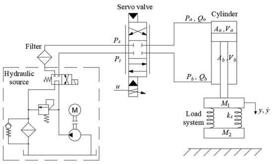
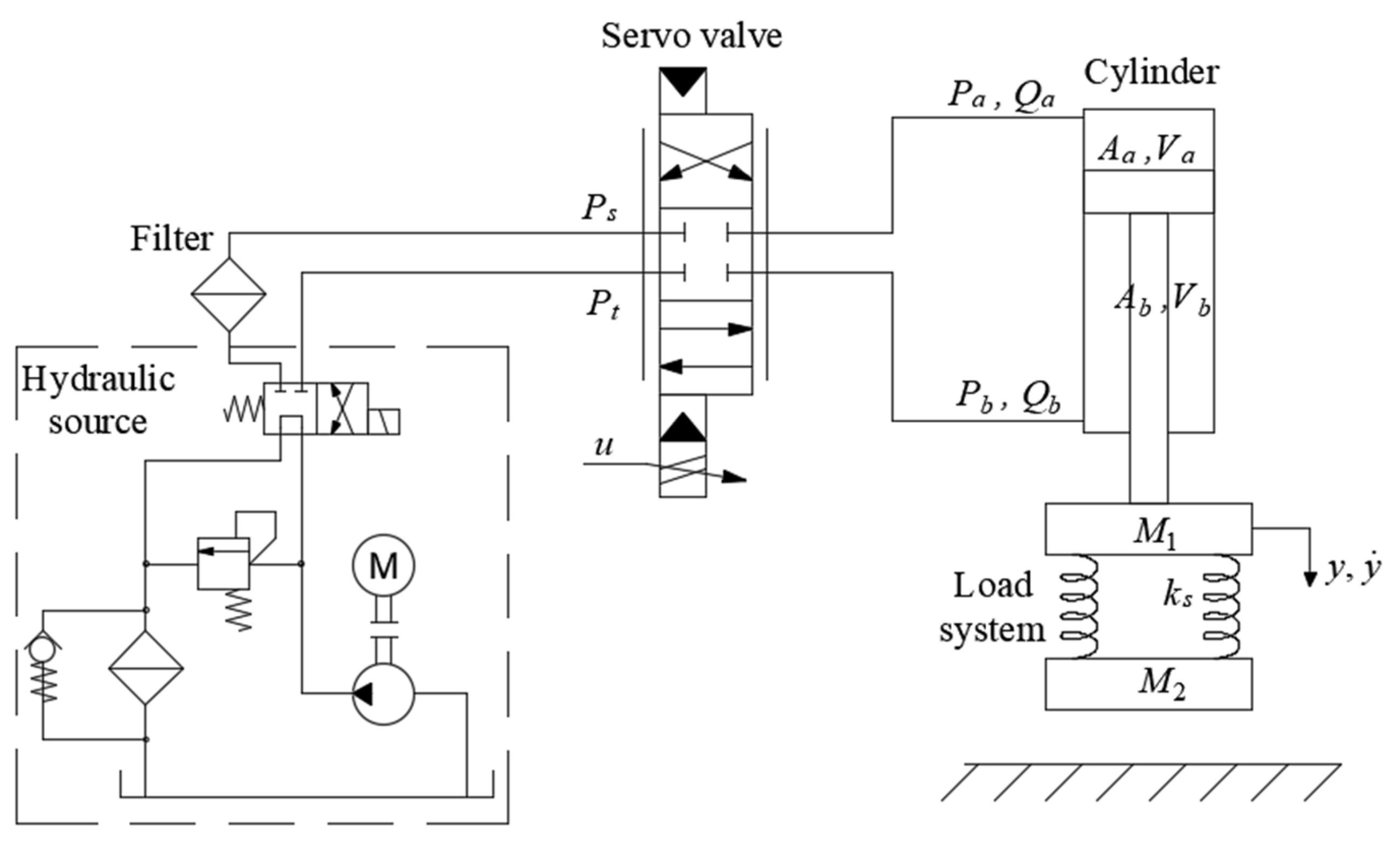
Figure 1 illustrates the schematic configuration of the electro-hydraulic servo cylinder system. The system consists of a vertically oriented, double-acting hydraulic cylinder, whose piston is mechanically coupled to a load assembly comprising two masses, M1 and M2, connected via two linear springs with a total equivalent stiffness denoted by ks. An electro-hydraulic servo valve is employed to regulate the flow of pressurized oil into and out of the cylinder chambers, thereby controlling the motion of the piston. The hydraulic oil is supplied from a standard source at a constant pressure Ps. The servo valve is actuated by an electrical input signal u, which determines the valve opening and consequently, the flow rate. For control-oriented modeling, the dominant mechanical and hydraulic dynamics of the system are considered, while secondary effects are either neglected or treated as bounded uncertainties in a simplified manner.
Figure 1.
Hydraulic servo cylinder system.
This section presents a simplified dynamic model of the electro-hydraulic servo system considered in this study. The model is developed with the primary objective of controller design and experimental implementation rather than high-fidelity system simulation. Modeling assumptions are introduced to balance analytical tractability and practical relevance for real-time control applications.
To facilitate real-time controller implementation, the high-frequency dynamics of the servo-valve spool are neglected, and the valve flow is approximated by a quasi-static nonlinear relationship. This control-oriented assumption is commonly adopted in electro-hydraulic control studies, where the dominant dynamics are governed primarily by actuator mechanics and fluid compressibility. In the present study, the experimental excitation frequencies are limited to 0.1–1 Hz, under which the system performance is mainly constrained by practical flow-rate and actuator bandwidth limitations. From a mechanical system perspective, the investigated excitation frequencies are well below the dominant spool and valve dynamics, such that the control-oriented approximation captures the actuator behavior relevant to closed-loop positioning performance. Accordingly, residual effects associated with neglected valve spool dynamics are treated as bounded uncertainties within the control design. Under this assumption, the corresponding flow control equation is given by:
where Qa and Qb denote the flow rates entering the upper and lower chambers of the hydraulic cylinder, respectively. The parameter cd is the discharge coefficient associated with the valve orifice, w is the circumferential width of the rectangular port machined into the valve sleeve, kv is the valve spool position gain, and ρ is the hydraulic oil density. Pa and Pb are the pressures in the upper and lower chambers of the hydraulic cylinder while Pt is the pressure at tank port of the servo valve.
Assuming that internal flow leakage within the hydraulic cylinder is sufficiently small compared with the commanded flow, the leakage effect is neglected for control-oriented modeling purposes. Any residual leakage and unmodeled hydraulic losses are treated as bounded disturbances in the control design. Under this assumption, the continuity equations governing the flow dynamics in the upper and lower chambers can be expressed as follows:
where and denote the total volumes of the upper and lower chambers, respectively, and Va0 and Vb0 represent the dead volumes of oil at the extremities of both chambers of the cylinder. and are the piston areas on each side, respectively. y and are the position and velocity of the piston, l is the piston stroke and is the effective bulk modulus of the hydraulic oil.
The equation describing the force equilibrium on the load piston assembly is formulated as follows:
where the effective mass M is defined as when and when . Here, M1 denotes the combined mass of the piston, the upper mass, and the spring assembly, while M2 represents the lower mass. The external load force fl is given by when and when , where g is the gravitational acceleration and is the equivalent spring stiffness. The term denotes the friction force arising from the hydraulic cylinder.
To represent the dominant friction phenomena observed in the hydraulic cylinder, the dynamic LuGre friction model [23] is adopted in this study. The model provides a favorable balance between descriptive capability and computational efficiency, making it well suited for real-time friction compensation in electro-hydraulic servo applications. Previous experimental investigations on hydraulic cylinders have shown that the LuGre framework can reproduce key steady-state and transient friction characteristics observed in practice—such as breakaway behavior and rate-dependent friction effects—when appropriate parameters are identified [16,17]. These empirical observations provide experimental motivation for selecting the LuGre model in the present study to support friction compensation under realistic operating conditions.
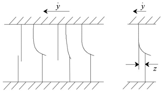
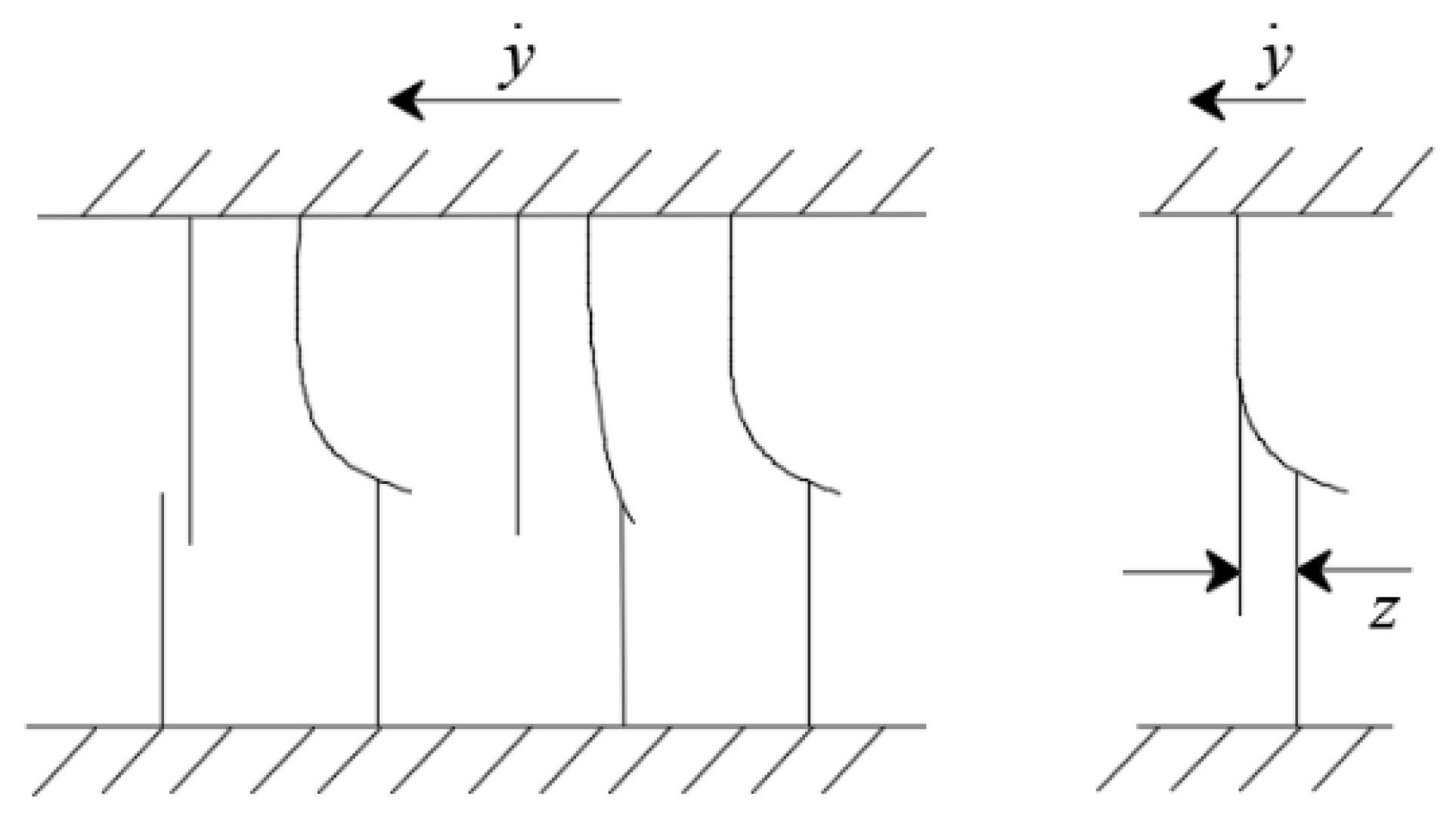
The LuGre model is based on the concept of bristle deformation, as illustrated in Figure 2. In this representation, the contact between surfaces is modeled using rigid asperities on one side and elastic bristles on the other. The internal state variable z representing the average deflection of the bristle-like elements evolves according to the following dynamic equation:
where denotes the stiffness of the elastic bristles. The Stribeck function is defined as
where denotes the Coulomb friction force, represents the static friction force, is the characteristic Stribeck velocity and n is a positive exponent shaping the Stribeck curve.
Figure 2.
Schematic representation of the bristle model.
The friction force is formulated as a function of the internal state variable z, as follows:
where and denote the micro-viscous and viscous friction coefficients, respectively. The first two terms in Equation (6) represent the resistive force associated with elastic bristle deformation and its internal dynamics, while the third term accounts for the viscous friction effect.
Under steady-state conditions, the friction force can be expressed as:
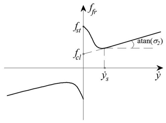
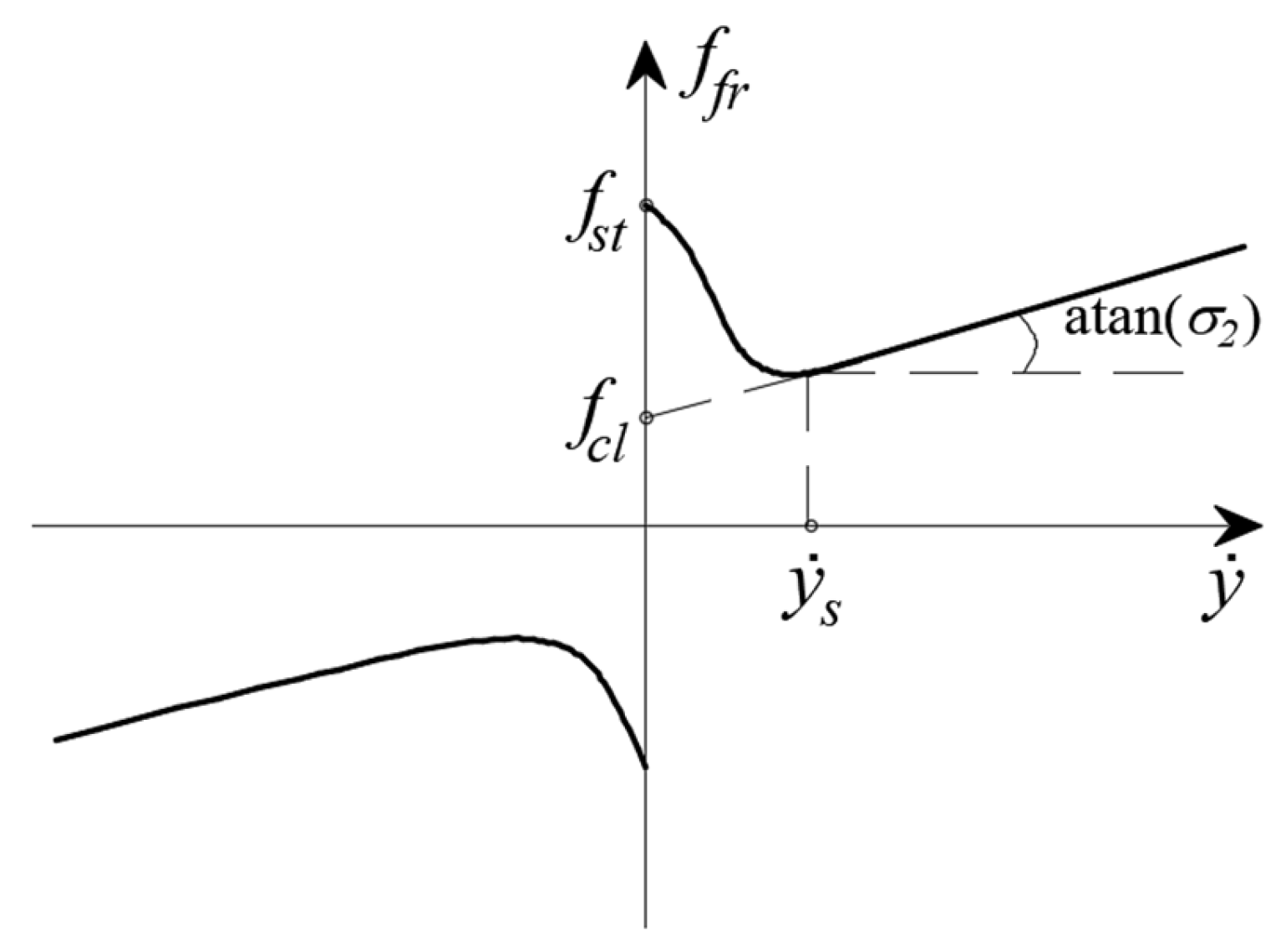
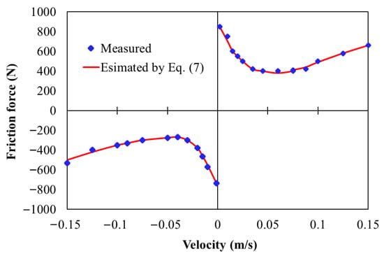
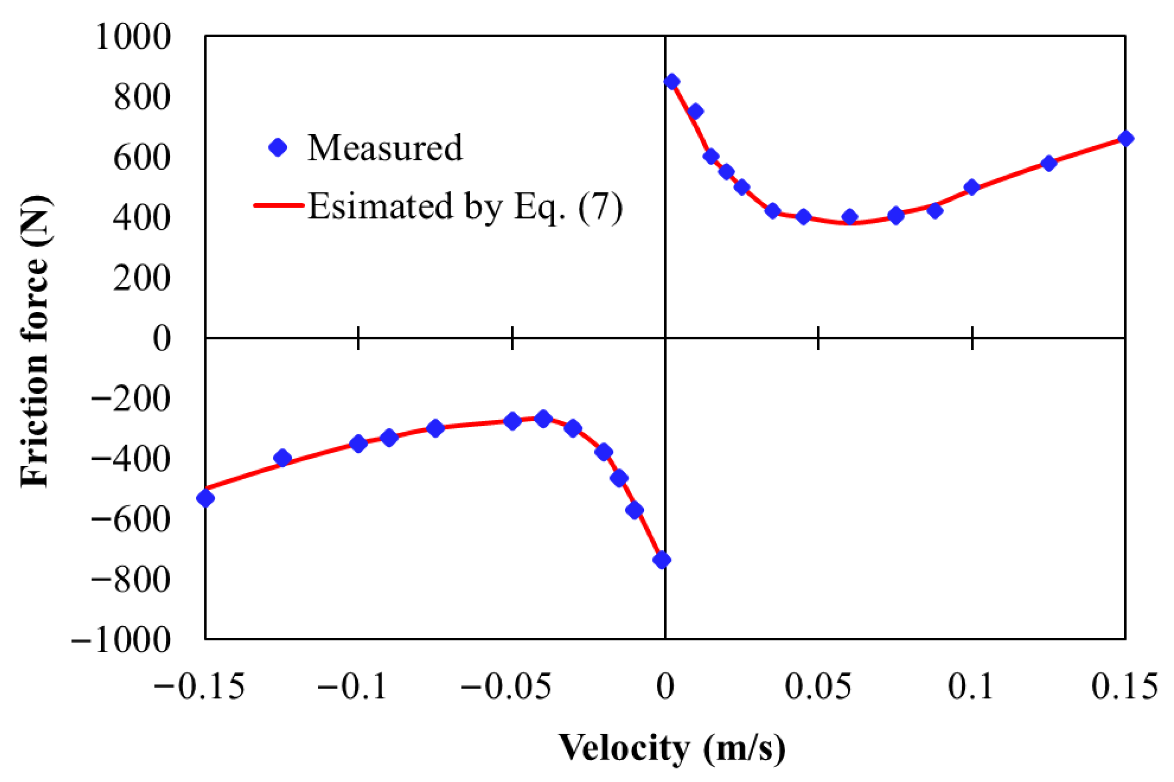
The steady-state characteristics of the friction force are illustrated in Figure 3, showing its variation with respect to the piston velocity. The figure reveals a nonlinear relationship in which the friction force decreases as the velocity increases, reflecting the typical Stribeck effect. This behavior indicates a transition from static-dominated to kinetic friction regimes, which is important for representing friction characteristics in motion control systems.
Figure 3.
Steady-state friction characteristics.
An experimental parameter identification procedure is employed for the LuGre friction model to support accurate friction compensation in the control design. The identification strategy follows the experimental approach reported in [17], where steady-state and dynamic friction characteristics of hydraulic cylinders were systematically characterized under controlled operating conditions. This procedure is designed to ensure consistency between the friction model and the physical system for control implementation, rather than to provide a comprehensive investigation of friction parameter estimation accuracy.
In this approach, the static parameters defined in Equation (7)—including the Coulomb friction force , the static friction force , the Stribeck velocity , the component n, and the viscous friction coefficient , are identified using the least-squares method. This identification is based on steady-state friction characteristics obtained from experimental measurements. Specifically, the hydraulic cylinder is driven at constant velocities, and the corresponding steady-state friction forces are recorded. These data points are then used to fit the static friction curve, minimizing the squared error between the measured and modeled friction forces.
The bristle stiffness parameter, , as specified in Equation (6), plays a crucial role in determining both the magnitude of the break-away friction force and the transient response of friction during velocity reversals. An increase in, , leads to a higher break-away force level and a faster force build-up, directly influencing the dynamic behavior of friction compensation. In this study, is identified using a quantitative experimental–simulation matching procedure rather than subjective tuning. Specifically, is selected by minimizing a mismatch criterion that combines (i) the relative error in the peak break-away friction force and (ii) the relative error in the rise time of the friction response under sinusoidal velocity excitation. This approach is consistent with control-oriented identification practices reported for hydraulic cylinders (e.g., [17]) and provides a reproducible and mechanically motivated basis for selecting suitable for real-time friction compensation.
The selection of adheres to the passivity constraint inherent in the LuGre friction formulation, as outlined below:
By synthesizing the relationships expressed in Equations (1) through (3), the dynamic model of the electro-hydraulic servo system can be expressed as:
By setting , and , Equation (9) can be reformulated into the following state-space representation:
where denotes the state vector of the system, and
Equations (10)–(12) indicate that the dynamics of the investigated electro-hydraulic servo system are strongly nonlinear, primarily due to the compressibility of the hydraulic fluid and the nonlinear flow–pressure characteristics of the servo valve. In addition, the system is subject to parameter uncertainties, including variations in the effective bulk modulus, valve flow coefficients, and load inertia. The presence of nonlinear friction forces further contributes to the complexity of the system dynamics. As a result, the combined effects of nonlinear dynamics, parameter uncertainties, and friction provide strong motivation for the use of robust nonlinear control approaches suitable for practical electro-hydraulic positioning applications.
3. Control Strategy
3.1. Controller Design
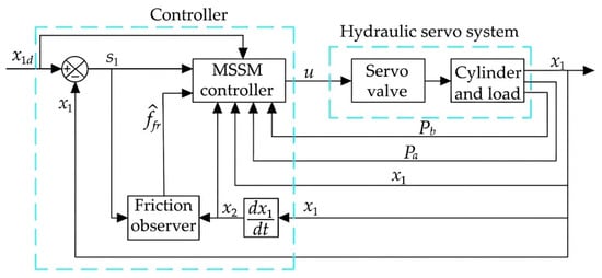
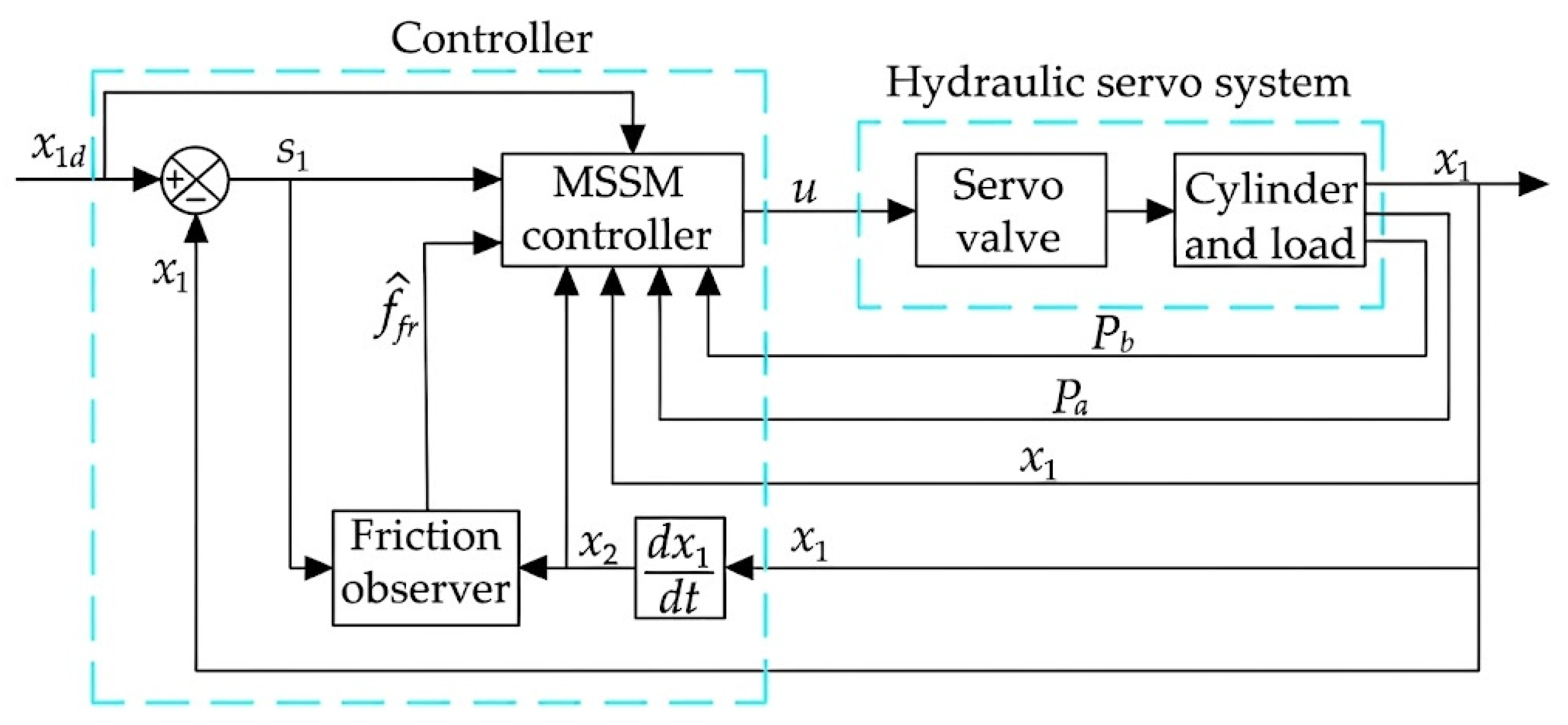
This section presents the design of a nonlinear control framework aimed at achieving reliable position tracking of an electro-hydraulic actuator under practical operating conditions. Accordingly, a control structure integrating a multi-surface sliding mode formulation with friction compensation based on the LuGre friction model is developed. The overall control architecture is illustrated in Figure 4. The multi-surface sliding mode (MSSM) structure is adopted to address the inherent nonlinearities, parameter uncertainties, and mismatched disturbances encountered in electro-hydraulic servo systems. By employing a hierarchical sliding-surface formulation, the MSSM approach enables structured regulation of position, velocity, and force-related dynamics while maintaining stable tracking behavior within predefined boundary layers under varying operating conditions. Such a formulation is particularly suitable for electro-hydraulic actuators, where robustness and real-time implementability are primary design considerations. To mitigate the influence of frictional forces arising from the hydraulic cylinder, a friction estimation mechanism based on the LuGre model is incorporated into the control framework as a compensation term. As discussed in Section 2, the LuGre model provides an efficient and mechanically consistent representation of dominant friction characteristics relevant to electro-hydraulic systems, while remaining compatible with real-time implementation. The integration of friction estimation enables dynamic compensation of friction-related effects during operation, thereby improving tracking performance, particularly under operating conditions where friction dynamics become significant. The proposed control design emphasizes robustness and implementation simplicity to facilitate experimental validation on the electro-hydraulic test bench, rather than introducing additional controller complexity.
Figure 4.
Control system diagram.
For control design and experimental implementation, the following assumptions are introduced to characterize typical operating conditions of the electro-hydraulic servo system.
Assumption 1.
The mass load acting on the piston is bounded, such that , where and denote the minimum and maximum effective load corresponding to the operating conditions of the experimental setup.
Assumption 2.
The piston velocity remains within a finite range given by , where represents the maximum admissible piston velocity determined by actuator capability and safety constraints.
Assumption 3.
The friction force generated within the hydraulic cylinder is bounded as: , where denotes the upper bound of the friction force under normal operating conditions. This bound is determined based on experimentally identified steady-state friction characteristics, including the static friction level obtained from low-velocity measurements.
Assumption 4.
The pressures in both actuator chambers remain within prescribed limits: , where and are denoted as the pressure at tank port of the servo valve and the hydraulic supply pressure, respectively.
It is emphasized that the assumptions introduced above do not represent abstract theoretical conditions but instead reflect the physically realizable operating envelopes of the experimental electro-hydraulic test bench. The effective load mass is determined by the mechanical configuration of the hydraulic cylinder, springs, and attached loads. The piston velocity and chamber pressures are inherently constrained by servo valve characteristics, hydraulic supply pressure, flow capacity, and safety limitations of the experimental setup. In addition, the admissible friction force bound is supported by the experimental identification results presented in Section 4.2. These operating bounds are introduced to facilitate a control-oriented Lyapunov analysis and to ensure bounded closed-loop behavior within physically realizable operating conditions. Accordingly, the stability analysis aims to establish practical stability and bounded tracking performance of the experimental system, rather than global stability under idealized or arbitrary conditions.
Based on these operating assumptions, conservative bounds on the nonlinear function f(x, t) are obtained for control design purposes as follows:
In Equation (12), the input-related function g(x,t) is assumed to vary within known bounds that characterize typical operating conditions of the electro-hydraulic system, i.e., , with its extremal values defined as follows:
A nominal value is introduced to represent typical system behavior under the operating conditions considered. Based on this nominal value, the corresponding deviation of with respect to is conservatively bounded for control design purposes as where denotes a bound reflecting practical operating limits rather than exact uncertainty knowledge.
The above bounds characterize the admissible variation in the system nonlinearities under the operating conditions considered. These conservative bounds are subsequently employed to support the sliding-surface design and controller formulation, with the objective of achieving stable tracking behavior in practical electro-hydraulic applications.
To formulate the control law for practical implementation, the following design steps are considered.
Step 1: The piston position tracking error is first defined as , and the corresponding sliding surface is introduced as . For subsequent controller formulation, the time derivative of this sliding surface is expressed as:
To shape the evolution of the position tracking error and support the hierarchical sliding-surface design of the MSSM framework, a virtual desired velocity x2d is introduced. Accordingly, the desired velocity x2d is chosen as
where denotes the boundary-layer parameter associated with the sliding surface which is introduced to mitigate chattering and facilitate practical implementation. The coefficient is a strictly positive design parameter selected to regulate the convergence behavior of the position tracking error under experimental operating conditions.
Based on the introduced virtual desired velocity, the piston velocity tracking error is considered next, and the corresponding sliding surface is introduced as . With the definition of the virtual desired velocity in (16), the position-level sliding surface dynamics can be expressed in terms of the second sliding surface. By combining Equations (15) and (16), the following relationship is obtained:
Step 2: To further develop the hierarchical sliding-surface formulation, the dynamics of the second sliding surface are considered. By incorporating the system dynamics in Equation (10) and the virtual desired velocity defined in Equation (16), the time derivative of s2 can be expressed as
To support force-level regulation within the MSSM framework, a virtual desired force variable is introduced, and the force-level sliding surface is defined as where the virtual desired force x3d is chosen as
where denotes the boundary-layer parameter associated with the sliding surface s2, which is introduced to smooth the control action and facilitate practical implementation. The coefficient is a strictly positive design parameter selected to regulate the convergence behavior of the force-level tracking error under experimental operating conditions. The estimated friction force is obtained using the LuGre friction model and is expressed as
The estimated bristle deformation evolves according to
where is a strictly positive design parameter selected to ensure stable friction estimation behavior in the presence of modeling uncertainties.
To characterize the evolution of the friction estimation error, the dynamics of the estimated bristle deformation are considered. By combining the LuGre friction model dynamics in Equation (4) with the estimation law in Equation (21), the time evolution of the estimated bristle deformation can be expressed as
Equation (22) describes the update law of the estimated friction state used for model-based friction compensation during control implementation. Based on the definitions of the velocity-level and force-level sliding surfaces, the time evolution of the second sliding surface can be expressed by combining Equations (18) and (19) as
This expression highlights how the force-level sliding surface and the friction compensation term jointly influence the evolution of the velocity-level tracking error under practical operating conditions.
Step 3: To complete the hierarchical sliding-surface formulation and derive the control law for practical implementation, the dynamics of the force-level sliding surface are considered. By incorporating the system dynamics in Equation (10), the time derivative of the third sliding surface can be expressed as
To evaluate the time derivative of the virtual desired force, the expression of is obtained by combining Equations (18) and (19) as
For clarity in the subsequent control design, the above expression is separated into a known component and an uncertainty-related component, such that
where the known component is constructed based on available reference signals and measurable state variables, while captures the influence of friction estimation uncertainty.
Based on the above formulation, the control law of the proposed scheme is expressed as
where denotes the boundary layer parameter associated with the sliding surface , introduced to smooth the control action, and is a strictly positive design parameter selected to regulate the convergence behavior of the force-level tracking error under practical operating conditions.
By substituting Equations (26) and (27) into Equation (24), the resulting closed-loop dynamics of the third sliding surface can be expressed as
To facilitate the subsequent stability analysis, conservative bounds on the terms and are considered under practical operating conditions. Based on the above expression, a conservative bound on the time derivative of the virtual desired velocity can be established as
Based on the bound of conservative bounds on the time derivative of the virtual desired force defined in Step 2 can be established. Accordingly, the known component of satisfies
In the nominal case without friction estimation error, the uncertainty-related component of the virtual desired force derivative vanishes, yielding
Equation (31) corresponds to the nominal compensation case in which the friction force is assumed to be accurately estimated, and its dynamic variation is effectively compensated by the LuGre-based friction estimation mechanism. In this case, the uncertainty-related component of the virtual desired force dynamics vanishes, although the physical friction force itself remains nonzero. This nominal analysis is adopted to clarify the structure of the closed-loop dynamics, while in practical implementations residual friction estimation errors are bounded and handled by the robustness of the sliding-mode control terms.
The bounds in Equations (29)–(31) characterize admissible operating limits and are employed in the subsequent Lyapunov-based analysis to establish sufficient stability conditions for practical electro-hydraulic positioning applications. Given the presence of actuator bandwidth limitations, unmodeled dynamics, and uncertainties in friction estimation, the control objective is formulated in terms of practical stability and ultimate boundedness, which represent appropriate and sufficient performance criteria for electro-hydraulic actuator control in experimental environments.
3.2. Stability Analysis
This section investigates the stability properties of the closed-loop electro-hydraulic actuator system under the proposed control scheme. The objective of this analysis is not to establish global asymptotic stability under idealized conditions, but rather to demonstrate practical stability and bounded tracking performance that are suitable for electro-hydraulic actuator control in experimental environments. This stability notion is appropriate given the presence of actuator bandwidth limitations, unmodeled dynamics, and bounded uncertainties associated with friction estimation and hydraulic nonlinearities. To this end, a Lyapunov-based analysis is carried out to assess the boundedness of the hierarchical sliding-surface variables and the friction estimation error. The following Lyapunov candidate function is considered:
where the Lyapunov function incorporates the position, velocity, and force-level sliding surfaces, as well as the internal friction estimation error state. This structure reflects the hierarchical nature of the multi-surface sliding mode control framework and the integration of dynamic friction compensation.
The time derivative of the Lyapunov function along the closed-loop system trajectories is given by
By substituting the sliding-surface dynamics derived in Equations (17), (21), (23) and (28) into (33), the time derivative of the Lyapunov function can be expressed as
To ensure negative semi-definiteness of the Lyapunov derivative, the control gains are selected according to the following conditions:
where , , , and are positive design constants. These selections are made to balance robustness and smoothness of the control action under practical operating conditions rather than to achieve aggressive theoretical convergence rates. By applying the parameter selections in (35) and considering the following bounded conditions on the friction terms and reference signals, , the time derivative of the Lyapunov function satisfies
If the boundary-layer parameters are selected such that , , , then the Lyapunov derivative can be further bounded as
This result indicates that all sliding-surface variables , , and , as well as the friction estimation error , remain bounded and converge to neighborhoods determined by the selected boundary layers determined by , , and . Consequently, the piston position tracking error is ultimately bounded around the desired trajectory. This stability behavior is characteristic of quasi-sliding-mode implementations with boundary layers and is sufficient for reliable electro-hydraulic actuator control in experimental environments where actuator saturation, bandwidth limitations, and unmodeled dynamics are unavoidable. Therefore, the proposed control scheme guarantees practical stability and bounded tracking performance of the electro-hydraulic system under physically realizable operating conditions, which aligns with the control objectives of industrial electro-hydraulic machines rather than idealized theoretical systems.
4. Experimental Evaluation
4.1. Experimental System
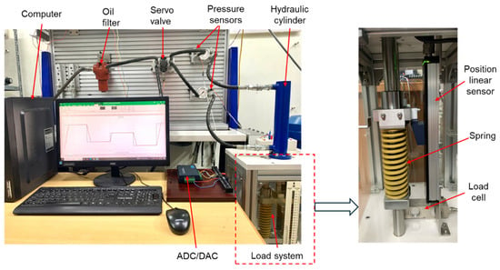
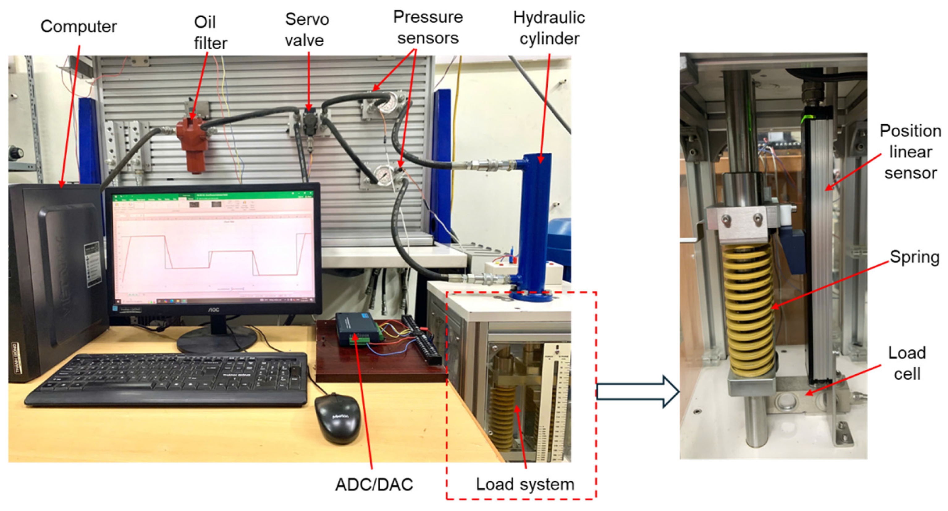
Experimental validation of the proposed control scheme was conducted using the electro-hydraulic actuator test platform shown in Figure 5. The system comprised a vertically mounted double-acting hydraulic cylinder driven by a 4/3 electro-hydraulic servo valve (Bosch Rexroth 4WSE2EM6, Bosch Rexroth AG, Lohr am Main, Germany), which is representative of actuator configurations commonly encountered in industrial electro-hydraulic machines. The servo valve was a two-stage valve with mechanical feedback, rated for a maximum operating pressure of 210 bar and a nominal flow rate of 10 L/min (±10% tolerance at a pressure drop of 70 bar). This flow capacity, together with the available hydraulic supply, constitutes a primary constraint on the achievable dynamic performance of the actuator. The hydraulic cylinder was mechanically coupled to a load system enclosed in a protective frame, as illustrated in the enlarged view of Figure 5. The load system consisted of a coaxially mounted compression spring, such that the external load acting on the piston varies with its displacement. As a result, changes in reference amplitude led to different operating positions and effective load levels, introducing position-dependent load variation that is representative of practical electro-hydraulic applications involving elastic or compliant loads.
Figure 5.
Image of the experimental system setup.
Piston displacement was measured using a high-precision linear position sensor (Novotechnik TF10200, Novotechnik Messwertaufnehmer OHG, Ostfildern, Germany) with sub-micrometer resolution (<1 µm) and a linearity of ±0.025% of full scale. Piston velocity and acceleration were obtained via numerical differentiation of the measured position signal. Chamber pressures in both cylinder chambers were measured using IFM PU8500 pressure sensors (IFM PU8500, IFM electronic GmbH, Essen, Germany) with a measuring range of 0–400 bar, an accuracy of ±0.8% of full scale, and a typical response time of approximately 2 ms. All sensor signals were acquired through an Advantech USB-4711A (Advantech Co., Ltd., Taipei, Taiwan) data acquisition module, providing 16 analog input channels with 12-bit resolution at a maximum aggregate sampling rate of 150 kS/s, as well as 12-bit analog output channels for control signal generation. As shown in the magnified view of Figure 5, a load cell was installed on the experimental test rig as part of the general laboratory setup for other studies. It is noted that the load cell was not used for data acquisition or analysis in the present work and did not contribute to the results reported in this paper.
The control algorithm was implemented in Microsoft Visual Studio (Visual Studio 2022, Microsoft Corp., Redmond, WA, USA) with a sampling interval of 5 ms, and the control signal was transmitted to the servo valve through the same data acquisition interface. Table 1 summarizes the key physical parameters of the experimental system. It is noted that the experimental platform is subject to practical limitations, including the flow-rate constraint of the servo valve, the elastic load characteristics, and the hydraulic supply capacity. These physical constraints impose an upper bound on the achievable tracking performance, particularly at higher excitation frequencies. Accordingly, the experimental evaluations are conducted over a frequency range of 0.1–1 Hz, spanning from quasi-static operation to the practical bandwidth limit of the electro-hydraulic actuatorunder load. Importantly, these limitations are explicitly accounted for in the control design and stability analysis presented in Section 3.1 and Section 3.2, ensuring consistency between the experimental system characteristics and the adopted control objectives.
Table 1.
Parameters of the hydraulic servo system.
4.2. Parameter Identification of the LuGre Friction Model
The parameters of the LuGre friction model were identified experimentally following the procedure described in Section 2 and subsequently incorporated into the control scheme for experimental evaluation. The objective of this identification is not to obtain a highly detailed friction model, but to determine representative parameter values corresponding to the operating conditions of the electro-hydraulic actuator used in the experiments. During the identification procedure, the hydraulic cylinder velocity was regulated using a proportional–integral (PI) controller with gains KP = 0.3 and KI = 0.1. This velocity control configuration enabled stable and repeatable piston motion over the investigated operating range, allowing steady-state friction characteristics to be reliably measured at discrete constant-velocity points.
Figure 6 presents the experimentally measured steady-state friction characteristics together with the model-based estimation obtained from Equation (7) using a least-squares fitting procedure. Positive velocities correspond to the extension stroke, while negative velocities correspond to piston retraction. The static LuGre parameters were identified by fitting the measured friction force data at discrete, constant-velocity operating points. The friction force was recorded at discrete piston velocity points versus the operating velocity range . Using the steady-state friction data shown in Figure 6, the static parameters of the LuGre friction model were identified by fitting Equation (7) to the measured friction characteristics via a least-squares procedure. For the positive velocity direction (extension stroke), the identified parameters are: = 920 N, = 220 N, , = 500 Ns/m, and n = 1.12. For the negative velocity direction (retraction stroke), the corresponding parameters are: = 800 N, = 180 N, , = 480 Ns/m, and n = 1.2. The quality of the steady-state fit was evaluated using the RMS error between the measured and modeled friction forces. The normalized RMS error was approximately 4.2% of the maximum steady-state friction force for the extension stroke and 3.6% for the retraction stroke, indicating a satisfactory representation of the dominant steady-state friction behavior for control-oriented modeling.
Figure 6.
Steady-state friction characteristics: experimental data versus model estimation based on Equation (7).
These experimental results reveal a noticeable asymmetry in both static friction and Coulomb friction levels between the extension and retraction motions of the hydraulic cylinder. Such asymmetry can be attributed to differences in seal deformation, pressure distribution, and mechanical loading conditions during bidirectional operation. Moreover, the relatively large static friction forces—on the order of 800–900 N—indicate that friction represents a significant disturbance relative to the available actuator force, particularly during low-velocity operation and near velocity reversals. This observation underscores the practical relevance of incorporating explicit friction compensation in the control scheme evaluated in the subsequent experimental studies.
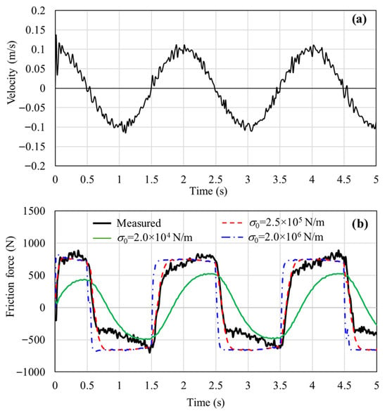
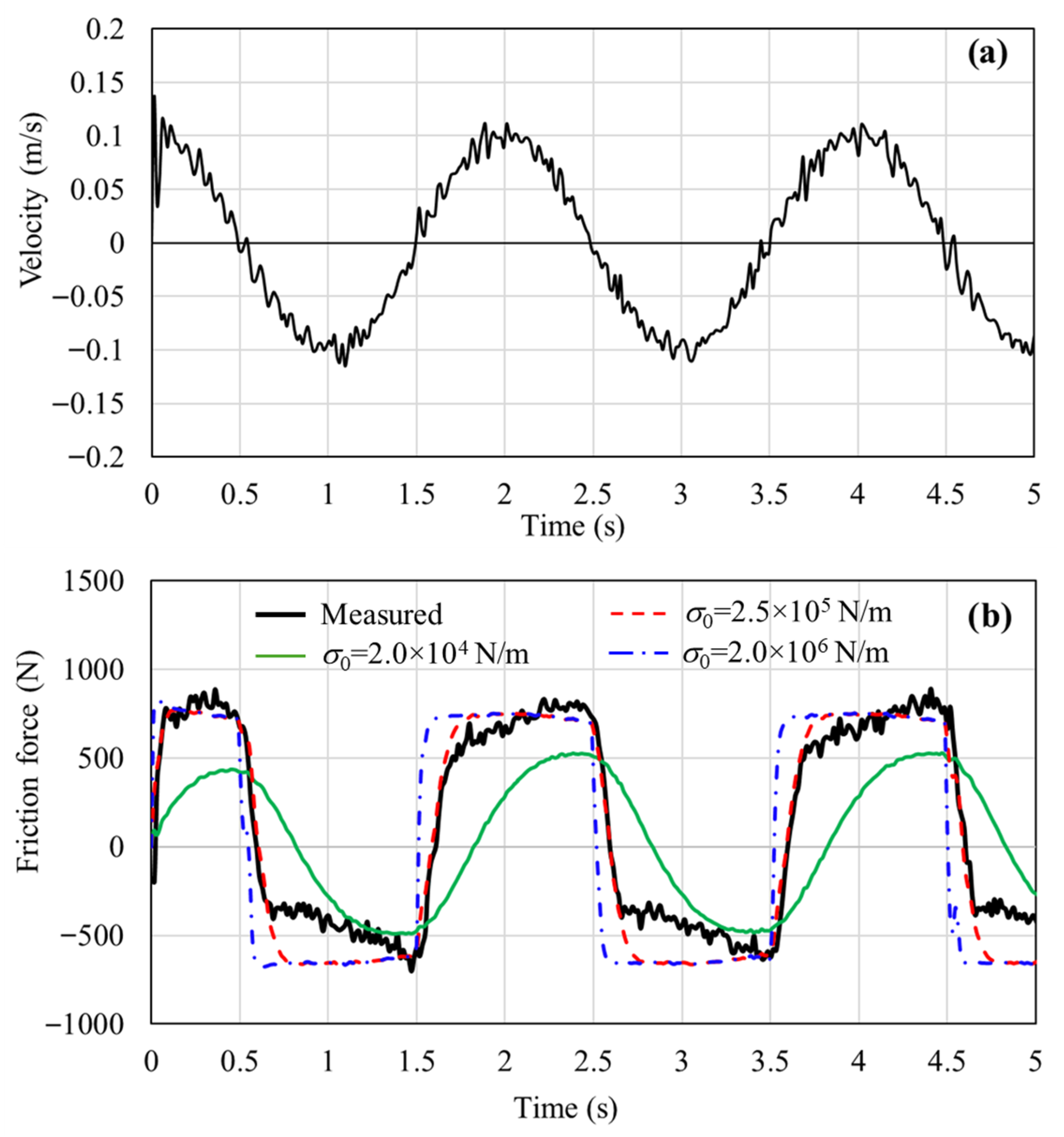
Figure 7 compares the experimentally measured friction force with the friction force simulated using the dynamic LuGre model under a sinusoidal piston velocity excitation, as shown in Figure 7a. Numerical simulations were performed in MATLAB/Simulink (R2018a) using different candidate values of the bristle stiffness parameter , which plays a key role in determining both the magnitude of the break-away friction force and the transient friction response during velocity reversals. Following the identification criterion described in Section 2, was determined using a quantitative experimental–simulation matching procedure. Specifically, for each candidate value of , a mismatch index was evaluated by combining (i) the relative error in the peak break-away friction force and (ii) the relative error in the rise time of the friction response under sinusoidal velocity excitation. Among the examined candidates, = 2.5 × 10⁵ N/m yielded the minimum overall mismatch. Using this value, the overall mismatch index was approximately 4.2% for the extension motion and 4.55% for the retraction motion, indicating a satisfactory representation of the dominant dynamic friction behavior for control-oriented purposes. Accordingly, = 2.5 × 10⁵ N/m was adopted as the representative bristle stiffness parameter for the hydraulic cylinder under investigation. Additional simulation studies conducted under different piston velocities and load conditions confirmed that this value of consistently captures the essential features of dynamic friction relevant to real-time friction compensation. Therefore, the selected σ0 represents a pragmatic compromise between modeling fidelity and real-time suitability, in line with the control-oriented objectives of this study.
Figure 7.
Experimental and simulated dynamic friction responses under sinusoidal piston velocity excitation: (a) piston velocity; (b) friction force for different values of the bristle stiffness parameter .
Based on the passivity condition defined in Equation (8), the micro-viscous friction coefficient was constrained to a bounded interval. The steady-state friction parameters and were identified separately for the positive and negative motion directions from the experimental friction characterization (Figure 6). Substituting the identified parameters into Equation (8) yields direction-dependent upper bounds for with a wider admissible range obtained for the positive motion direction (). Simulation results revealed that variations in σ1 within this admissible range exert minimal influence on the overall dynamic friction characteristics of the system. Consequently, a representative value of = 10 Ns/m was adopted for the experimental implementation, which satisfies the passivity condition for both motion directions.
With the identified parameters, the LuGre model can reproduce the dominant steady-state and transient friction characteristics observed in the hydraulic cylinder, including breakaway behavior and rate-dependent friction effects under time-varying velocity conditions. These friction characteristics provide a physically meaningful basis for interpreting the experimental control results presented in Section 4.3, where the influence of dynamic friction becomes increasingly apparent as the excitation frequency increases.
4.3. Evaluation Results
This section presents an experimental comparison of the proposed multiple-surface sliding mode controller with friction compensation (MSSM-FC) and two baseline controllers: a conventional proportional–integral–derivative (PID) controller and a multiple-surface sliding mode controller without friction compensation (MSSM). All experiments were conducted under identical reference trajectories and operating conditions to isolate the effect of explicit friction compensation on the tracking performance of the electro-hydraulic actuator. To ensure consistency with the experimental evaluation framework adopted in this study, tracking performance is evaluated primarily using the root-mean-square (RMS) position tracking error. This metric reflects cumulative tracking accuracy over an entire motion cycle and is less sensitive to transient outliers than peak error measures, making it particularly suitable for assessing electro-hydraulic actuators operating under friction and bandwidth limitations. Peak tracking errors are reported only as supplementary indicators to characterize worst-case deviations. Percentage performance improvements discussed in this section therefore refer to the relative reduction in RMS tracking error with respect to the baseline controllers. Controller parameters for all three controllers were initially selected through simulation using identical reference signals and subsequently fine-tuned experimentally to ensure stable operation and smooth control action under practical operating constraints, rather than to achieve aggressive performance optimization. The final controller parameters used in the experimental evaluation are summarized in Table 2. For the MSSM and MSSM-FC controllers, identical MSSM structural parameters and boundary-layer settings were used, such that the inclusion of the LuGre-based friction compensation term represents the only structural difference between the two control schemes.
Table 2.
Parameters of the three controllers.
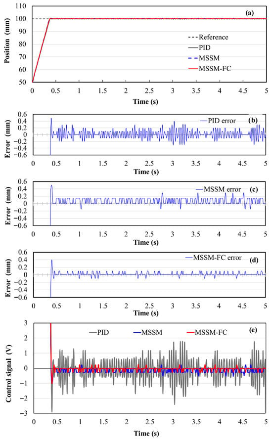
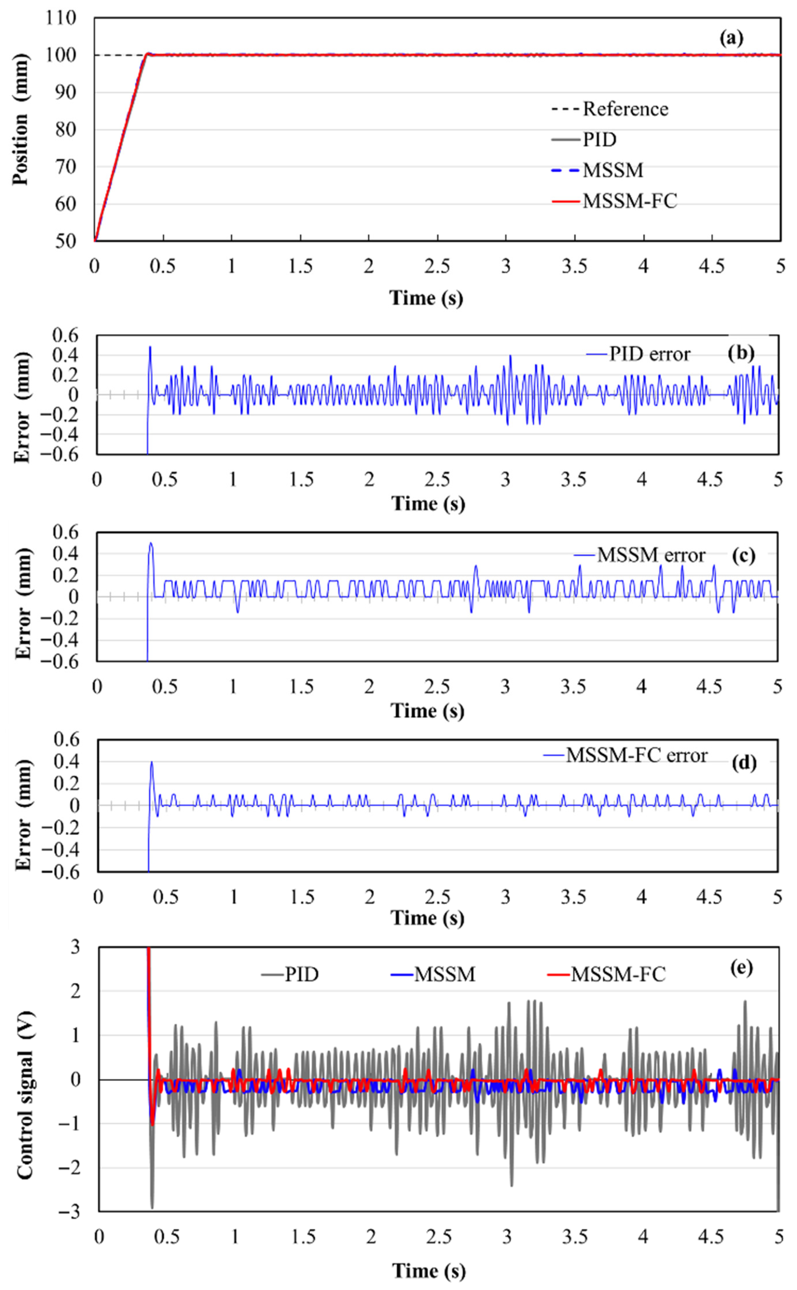
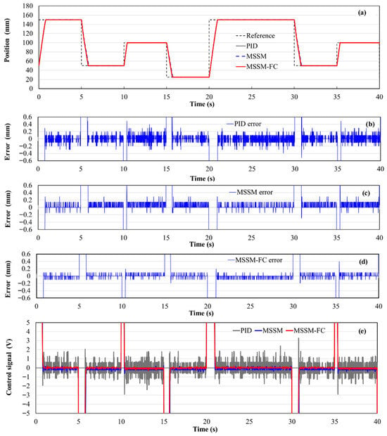
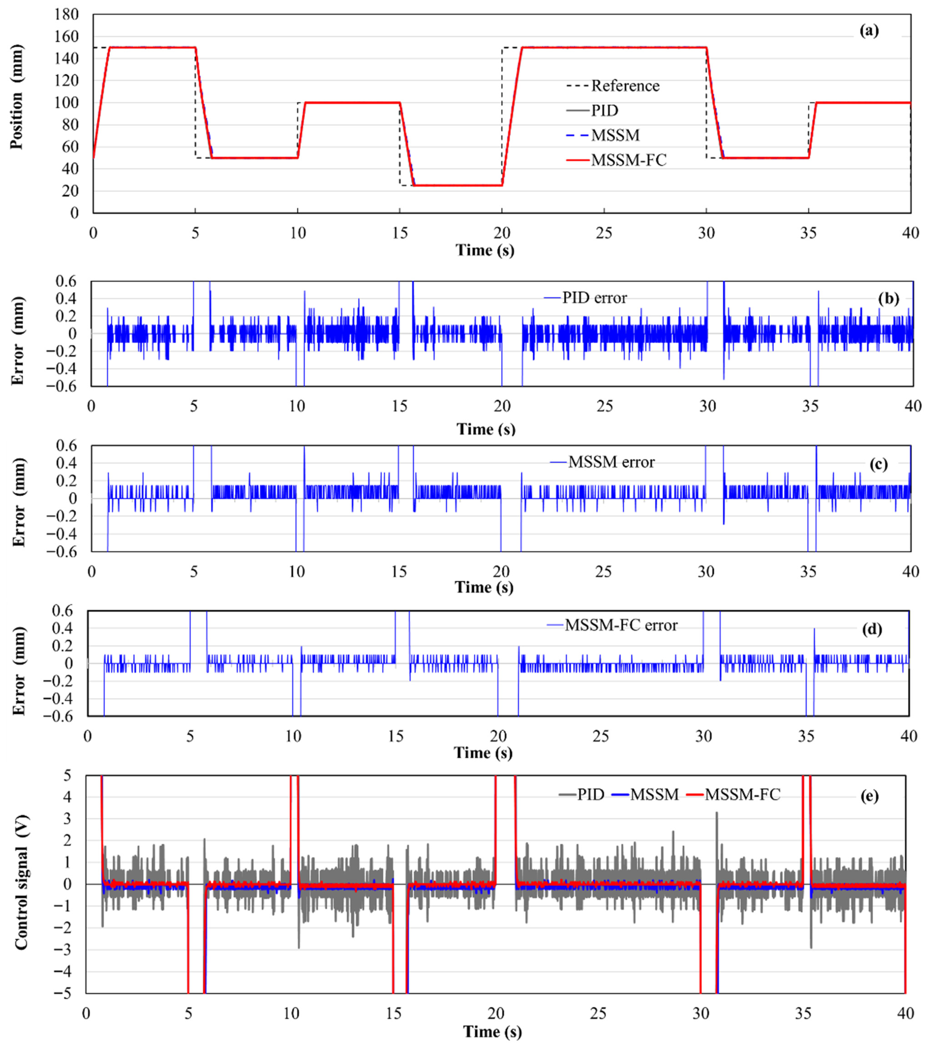
Figure 8 shows the experimental responses of the three controllers to a step position command with an amplitude of 100 mm. All controllers achieve similar transient responses with a settling time of approximately 0.406 s, which corresponds to the maximum achievable speed of the experimental system and is primarily constrained by the hydraulic flow capacity. Under this condition, no meaningful difference in transient speed can be attributed to controller structure. In steady state, however, clear differences in positioning accuracy are observed. The maximum steady-state position error is approximately 0.40 mm for the PID controller, 0.30 mm for the MSSM controller, and 0.10 mm for the proposed MSSM-FC controller. These results indicate that static friction and breakaway effects remain significant even at near-zero velocity and introduce a nonlinear dead zone when friction is not explicitly compensated. By incorporating dynamic friction estimation, the MSSM-FC controller effectively mitigates this effect and improves steady-state positioning accuracy. The corresponding control inputs shown in Figure 8e further reveal smoother actuator commands for the MSSM-FC controller, which is beneficial for practical implementation.
Figure 8.
Experimental responses of PID, MSSM, and MSSM-FC controllers to a step position input: (a) piston position tracking; (b–d) control errors of PID, MSSM, and MSSM-FC controllers, respectively; (e) servo valve control signal.
Figure 9 extends the step response comparison to different displacement amplitudes and motion directions. Across the tested range, the MSSM-FC controller consistently maintains low steady-state errors, whereas the PID and MSSM controllers exhibit larger variations depending on the displacement amplitude and direction of motion. This behavior is consistent with the experimentally observed asymmetric and position-dependent friction characteristics and indicates that explicit friction compensation effectively mitigates breakaway and dead-zone effects under quasi-static operating conditions. The results further demonstrate that the proposed controller preserves steady-state positioning accuracy across varying operating conditions, without sensitivity to motion direction or displacement amplitude.
Figure 9.
Experimental responses of PID, MSSM, and MSSM-FC controllers under various step position inputs: (a) piston position tracking; (b–d) control errors corresponding to PID, MSSM, and MSSM-FC controllers, respectively; (e) servo valve control signal.
It should be noted that, due to the presence of elastic elements in the load assembly, the external load acting on the piston is inherently position-dependent. As a result, changing the displacement amplitude leads to different piston operating positions and thus different equivalent load levels experienced by the actuator. The consistent tracking performance observed in Figure 9 indicates that the proposed MSSM-FC controller maintains bounded tracking accuracy despite position-dependent load variations. From a control-oriented perspective, these results provide experimental evidence of practical robustness with respect to operating condition variations associated with both friction asymmetry and load changes induced by piston position.
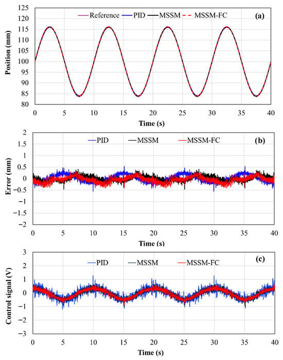
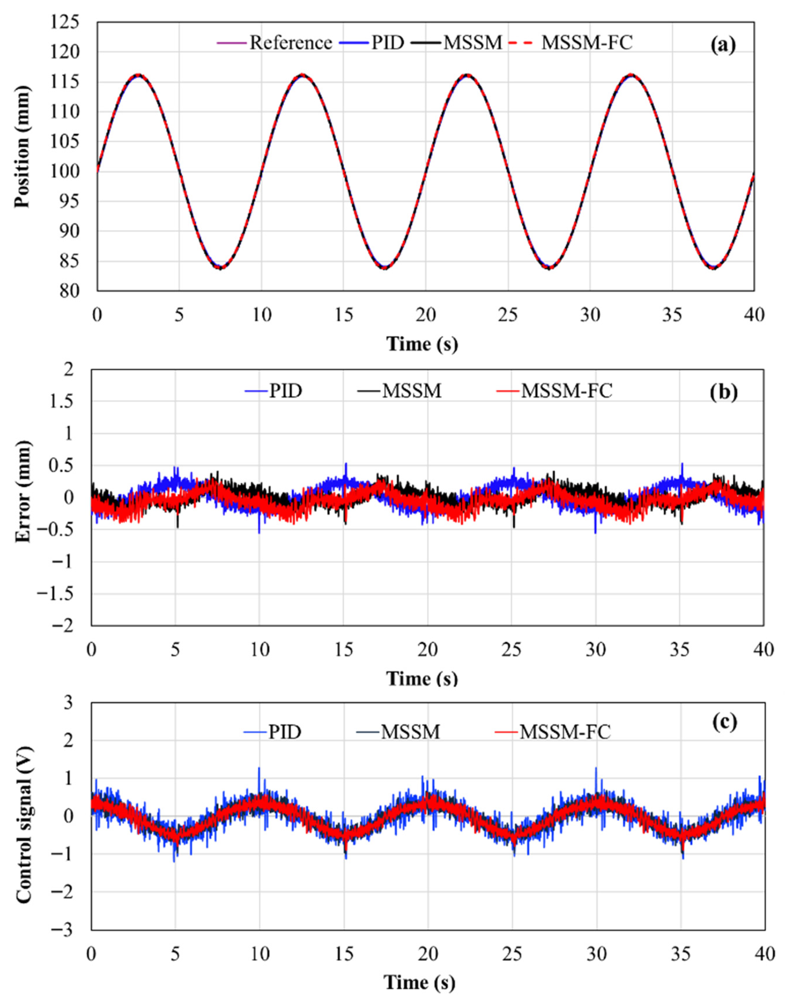
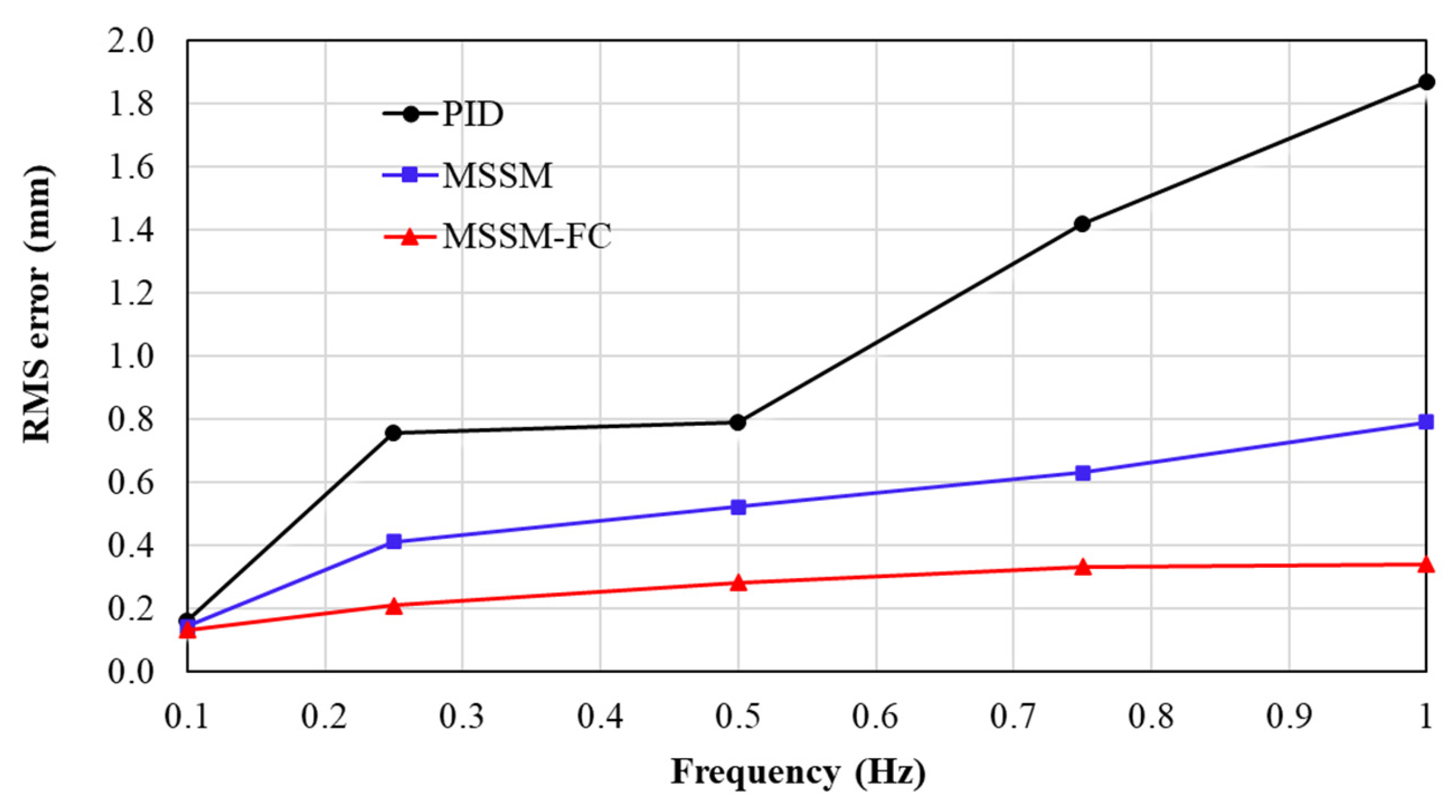
Figure 10 presents the experimental results for sinusoidal position tracking at a low excitation frequency of 0.1 Hz. Under this operating condition, piston velocities are small, and friction dynamics exert a limited influence on the overall closed-loop behavior, while position-dependent load variations are present due to the elastic elements of the mechanical system. The RMS tracking errors corresponding to this case are 0.16 mm for the PID controller, 0.14 mm for the MSSM controller, and 0.13 mm for the MSSM-FC controller. These results correspond to an RMS-error reduction of approximately 7% relative to the MSSM controller and about 19% relative to the PID controller. Although the improvement relative to the PID controller appears noticeable, the additional benefit of explicit friction compensation beyond robust MSSM control remains limited at this low excitation frequency. This indicates that, under slow-motion operating conditions, friction primarily behaves as a bounded disturbance, and its dynamic effects are relatively weak. Consequently, robust sliding mode control without explicit friction modeling already provides satisfactory RMS tracking performance, and explicit friction compensation yields only marginal additional improvement over MSSM.
Figure 10.
Experimental evaluation of the three controllers under a sinusoidal position reference x1d = 100 + 16sin(2πft) mm, with frequency f = 0.1 Hz: (a) piston position response; (b) tracking error; (c) control input to the servo valve.
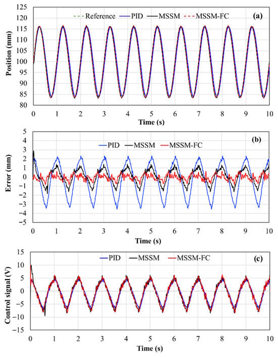
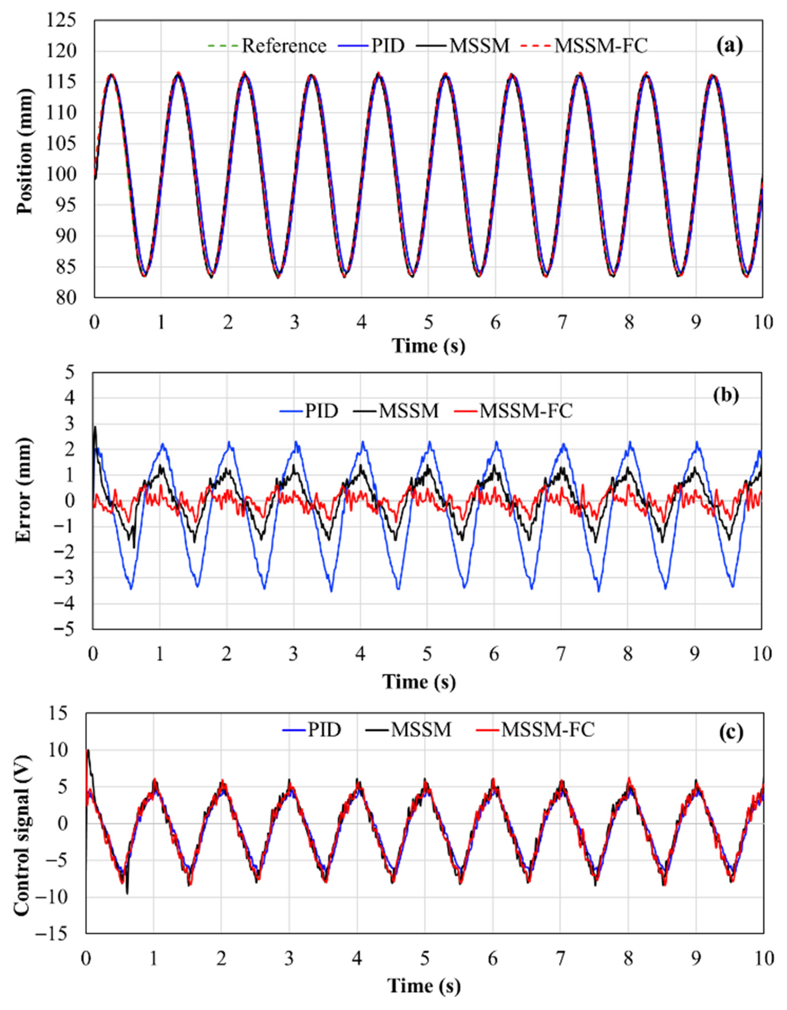
The influence of friction compensation becomes substantially more pronounced as the excitation frequency increases. Figure 11 shows the tracking performance for sinusoidal motion at 1 Hz, which approaches the practical bandwidth limit of the electro-hydraulic actuator used in the experiments. At this operating condition, the RMS tracking error of the proposed MSSM-FC controller is 0.34 mm, compared with 0.79 mm for the MSSM controller and 1.87 mm for the PID controller. These values correspond to RMS-error reductions of approximately 57% relative to MSSM and 82% relative to PID, demonstrating a significant advantage of explicit dynamic friction compensation during high-speed cyclic motion, where both velocity-dependent friction dynamics and position-dependent load variations are simultaneously present. Detailed inspection of the tracking error waveforms reveals that the dominant error contributions of the PID and MSSM controllers occur during high-velocity segments of motion, particularly near velocity reversals where rate-dependent friction hysteresis and breakaway effects dominate. By explicitly estimating and compensating these friction dynamics using the LuGre model, the MSSM-FC controller effectively suppresses these error components, resulting in markedly improved cumulative tracking accuracy.
Figure 11.
Experimental evaluation of the three controllers under a sinusoidal position reference x1d = 100 + 16sin(2πft) mm, with frequency f = 1 Hz: (a) piston position response; (b) tracking error; (c) control input to the servo valve.
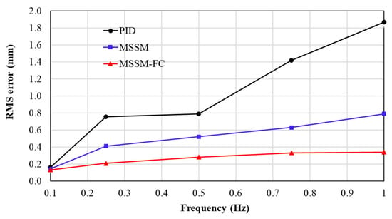
Table 3 summarizes the peak and RMS tracking errors of the three controllers over excitation frequencies ranging from 0.1 Hz to 1 Hz. For a clearer visualization of the frequency-dependent trend, Figure 12 plots the RMS tracking error as a function of excitation frequency for the three controllers based on the data reported in Table 3. As the excitation frequency increases, tracking errors grow for all controllers due to the combined influence of actuator bandwidth limitations and velocity-dependent friction dynamics. However, the rate at which the RMS tracking error increases with frequency is noticeably lower for the MSSM-FC controller. Across the entire frequency range considered, the MSSM-FC controller consistently achieves the lowest RMS error levels, with its performance advantage becoming more pronounced as the excitation frequency approaches the practical bandwidth limit of the electro-hydraulic actuator. These results indicate that dynamic friction effects, which are relatively insignificant during low-speed motion, progressively become a dominant source of cumulative tracking error as piston velocity increases. Consequently, the influence of friction can no longer be adequately treated as a simple bounded disturbance under high-frequency or cyclic operating conditions.
Table 3.
Peak position errors and RMS position errors of the three controllers with the sinusoidal position input x1d = 100 + 16sin(2πft) m at various frequencies.
Figure 12.
RMS position tracking error versus excitation frequency for the PID, MSSM, and MSSM-FC controllers (data extracted from Table 3).
Overall, the experimental results demonstrate that the effectiveness of explicit friction compensation is strongly dependent on the operating regime. At low excitation frequencies, where piston motion is slow and friction dynamics are weak, explicit friction compensation provides only limited improvement over robust sliding mode control without friction modeling. In contrast, as the excitation frequency approaches the practical bandwidth limit of the electro-hydraulic system, rate-dependent friction dynamics become comparable to actuator dynamics and emerge as a key limitation on tracking performance.
From a control-oriented perspective, these findings indicate that treating friction solely as an unstructured bounded disturbance may be insufficient for high-speed or cyclic positioning applications. Explicit friction modeling and compensation become necessary to maintain acceptable RMS tracking performance under such conditions, whereas simpler robust control strategies remain sufficient for low-speed operation. This experimentally grounded clarification of when friction compensation is beneficial and when it represents unnecessary complexity constitutes a key contribution of the present study and provides practical guidance for controller selection in electro-hydraulic positioning systems.
5. Conclusions
This paper has presented an experimental evaluation of explicit dynamic friction compensation for electro-hydraulic actuators operating under practical bandwidth constraints. A multi-surface sliding mode control framework integrated with a LuGre-based friction estimation mechanism was implemented on a laboratory-scale electro-hydraulic servo system and evaluated under step and sinusoidal reference motions over a range of excitation frequencies. The experimental results show that the influence of friction on closed-loop positioning performance is strongly dependent on the operating regime.
At low excitation frequencies, where piston velocities are small and friction dynamics are relatively weak, robust multi-surface sliding mode control without explicit friction modeling is sufficient to maintain bounded RMS tracking errors, and friction compensation yields only marginal additional benefit. In contrast, as the excitation frequency approaches the practical bandwidth limit of the electro-hydraulic system, rate-dependent friction phenomena—such as hysteresis, breakaway effects, and friction lag—become comparable to actuator dynamics and emerge as a dominant limitation on tracking accuracy. Under these high-speed or cyclic operating conditions, the proposed LuGre-based friction compensation integrated within the MSSM framework achieves substantial reductions in RMS tracking error, exceeding 50% relative to an MSSM controller without friction compensation and more than 80% compared with a conventional PID controller, while preserving closed-loop stability and smooth control action.
From a control-oriented mechanical engineering perspective, the results further indicate practical robustness with respect to variations in operating regimes, including excitation frequency and position-dependent load effects, which are sufficient for bandwidth-limited electro-hydraulic positioning applications. Overall, these findings highlight that friction compensation is not universally beneficial across all operating conditions of electro-hydraulic machines. Its effectiveness becomes significant primarily during high-speed or cyclic motion near actuator bandwidth limits, whereas under low-speed or quasi-static operation, simpler robust control strategies may already provide adequate accuracy. A limitation of the present study is that the experimental comparison focuses on PID and MSSM baselines to isolate the specific contribution of explicit LuGre-based friction compensation within a consistent control structure. Comprehensive benchmarking against advanced electro-hydraulic control strategies, such as adaptive robust control or disturbance observer-based schemes, is identified as an important direction for future work.
Author Contributions
Conceptualization, B.T.X.; methodology, B.T.X., P.P.P. and H.N.N.; software and validation, P.P.P. and H.N.N.; formal analysis, B.T.X., P.P.P. and H.N.N.; writing—original draft preparation, P.P.P.; writing—review and editing, B.T.X. and H.N.N.; project administration and funding acquisition B.T.X. All authors have read and agreed to the published version of the manuscript.
Funding
This research was funded by the Ministry of Education and Training, grant number B2024-BKA-14.
Data Availability Statement
Data is contained within the article.
Conflicts of Interest
The authors declare no conflicts of interest.
Abbreviations
The following abbreviations are used in this manuscript:
| MSSM | Multiple-surface sliding mode |
| MSSM-FC | Multiple-surface sliding mode controller with friction compensation |
| PI | Proportional—Integral |
| PID | Proportional—Integral—Derivative |
| SMC | Sliding mode control |
| RMS | Root mean square |
References
- Lee, S.U.; Chang, P.H. Control of a heavy-duty robotic excavator using time delay control with an integral sliding surface. Control Eng. Pract. 2002, 10, 697–711. [Google Scholar] [CrossRef] [Scilit]
- Wu, M.C.; Shih, M.C. Simulated and experimental study of hydraulic anti-lock braking systems using sliding mode PWM control. Mechatronics 2003, 13, 331–351. [Google Scholar] [CrossRef] [Scilit]
- Li, G.; Khajepour, A. Robust control of a hydraulically driven flexible arm using backstepping technique. J. Sound Vib. 2005, 280, 759–775. [Google Scholar] [CrossRef] [Scilit]
- Raade, J.W.; Kazerooni, H. Analysis and design of a novel hydraulic power source for mobile robots. IEEE Trans. Autom. Sci. Eng. 2005, 2, 226–232. [Google Scholar] [CrossRef]
- Wang, L.; Gong, G.; Yang, H.; Zhang, L.; Liu, Z. Development of a high-speed segment erecting system for shield tunneling machines. IEEE/ASME Trans. Mechatron. 2013, 18, 1713–1723. [Google Scholar] [CrossRef] [Scilit]
- Guan, C.; Pan, S. Adaptive sliding-mode control of an electro-hydraulic system with nonlinear unknown parameters. Control Eng. Pract. 2008, 16, 1275–1284. [Google Scholar] [CrossRef] [Scilit]
- Guo, K.; Wei, J.; Fang, J.; Wang, Y.; Liu, Y. Position tracking control of an electro-hydraulic single-rod actuator based on an extended disturbance observer. Mechatronics 2015, 27, 47–56. [Google Scholar] [CrossRef] [Scilit]
- Shen, W.; Huang, H.; Wang, J. Robust backstepping sliding-mode controller for an electro-hydraulic servo system. Asian J. Control 2019, 21, 302–311. [Google Scholar] [CrossRef] [Scilit]
- Liu, Y.; Handroos, H. Sliding-mode control for a class of hydraulic position servo systems. Mechatronics 1999, 9, 111–123. [Google Scholar] [CrossRef] [Scilit]
- Al-Samarraie, A.S.; Mahdi, S.; Mohammadridha, T.; Alkhayyat, A.; Al-Akaidi, M. Sliding-mode control for electro-hydraulic servo systems. Eng. J. 2015, 15, 1–10. [Google Scholar]
- Sun, C.; Dong, X.; Wang, M.; Li, J. Sliding mode control of electro-hydraulic position servo system based on adaptive reaching law. Appl. Sci. 2022, 12, 6897. [Google Scholar] [CrossRef] [Scilit]
- Tang, R.; Zhang, Q. Dynamic sliding-mode control scheme for electro-hydraulic position servo systems. Procedia Eng. 2013, 24, 28–32. [Google Scholar] [CrossRef] [Scilit]
- Tsai, Y.-T.; Huang, A.C. Multiple-surface sliding controller design for pneumatic servo systems. Mechatronics 2008, 18, 506–512. [Google Scholar] [CrossRef] [Scilit]
- Armstrong-Helouvry, B. Control of Machines with Friction; Kluwer Academic Publishers: Dordrecht, The Netherlands, 1991. [Google Scholar]
- Yanada, H.; Sekikawa, Y. Modeling of dynamic behaviors of friction. Mechatronics 2008, 18, 330–339. [Google Scholar] [CrossRef] [Scilit]
- Tran, X.B.; Matsui, A.; Yanada, H. Effects of viscosity and oil type on dynamic friction behavior of hydraulic cylinders. Trans. JFPS 2010, 41, 28–35. [Google Scholar]
- Tran, X.B.; Hafizah, N.; Yanada, H. Modeling of dynamic friction behaviors of hydraulic cylinders. Mechatronics 2012, 22, 65–75. [Google Scholar] [CrossRef] [Scilit]
- Pan, C.; Wang, Y.; Yang, S.X.; Li, Z.; Xiao, J. Compensation function observer-based backstepping sliding-mode control of uncertain electro-hydraulic servo systems. Machines 2024, 12, 719. [Google Scholar] [CrossRef] [Scilit]
- Armstrong-Helouvry, B.; Dupont, P.; Canudas-de-Wit, C. A survey of models, analysis tools and compensation methods for the control of machines with friction. Automatica 1994, 30, 1083–1138. [Google Scholar] [CrossRef] [Scilit]
- Lampaert, V.; Swevers, J.; Al-Bender, F. Modification of the Leuven integrated friction model structure. IEEE Trans. Autom. Control 2002, 47, 683–687. [Google Scholar] [CrossRef] [Scilit]
- Dupont, P.; Hayward, V.; Armstrong, B.; Altpeter, F. Single-state elastoplastic friction models. IEEE Trans. Autom. Control 2002, 47, 787–799. [Google Scholar] [CrossRef]
- Al-Bender, F.; Lampaert, V.; Swevers, J. The generalized Maxwell-slip model. IEEE Trans. Autom. Control 2005, 50, 1883–1887. [Google Scholar] [CrossRef] [Scilit]
- Canudas-de-Wit, C.; Olsson, H.; Åström, K.J.; Lischinsky, P. A new model for control of systems with friction. IEEE Trans. Autom. Control 1995, 40, 419–425. [Google Scholar] [CrossRef] [Scilit]
- Liao, J.; Zhou, F.; Zheng, J. Improved parameter identification for friction model in electro-hydraulic systems. Sensors 2023, 23, 2076. [Google Scholar] [CrossRef] [Scilit]

Disclaimer/Publisher’s Note: The statements, opinions and data contained in all publications are solely those of the individual author(s) and contributor(s) and not of MDPI and/or the editor(s). MDPI and/or the editor(s) disclaim responsibility for any injury to people or property resulting from any ideas, methods, instructions or products referred to in the content. |
© 2026 by the authors. Licensee MDPI, Basel, Switzerland. This article is an open access article distributed under the terms and conditions of the Creative Commons Attribution (CC BY) license.