


Abstract
Inspection inside small-diameter pipelines is difficult because the narrow interior space limits the field of view of onboard cameras. Even when a crack is successfully detected, it may still appear near the image boundary rather than in a suitable position for observation. To address this issue, this study proposes a vision-guided active crack alignment framework for small-diameter pipe inspection robots. The proposed framework uses a YOLOv5s detector to identify the crack region and extract the center of the detected bounding box. The positional difference between the crack center and the image center is defined as the image-plane alignment error. After low-pass filtering, this error is converted into actuator-side reference input through a pixel-to-motor mapping, and a PID-based closed-loop controller is used to regulate a local camera adjustment mechanism so that the detected crack region moves toward the image center. The framework is evaluated mainly through simulation, including controller comparison, different initial offset conditions, parameter sensitivity analysis, robustness tests under visual fluctuation and mapping uncertainty, and an ablation study. The controller comparison shows that all tested PID-based controllers achieve stable convergence, while the fuzzy PID controller provides the best overall performance among the tested cases in terms of settling time, steady-state error, and RMS error. The framework also remains stable under different crack positions and moderate uncertainty conditions. In addition, a preliminary laboratory-scale physical consistency test is conducted to examine whether the convergence tendency observed in simulation can also be reproduced under real visual feedback and actuator response. The preliminary physical results show a convergence tendency consistent with the simulation trend, thereby providing initial support for the practical implementability of the proposed detection-driven alignment concept. Complete integration with an in-pipe robot platform and validation under realistic pipe environments remain future work.
1. Introduction
Small-diameter pipelines are used in many industrial and infrastructure systems, and cracks that develop during long-term service can affect their safety and reliability [1,2]. However, inspecting the inside of such pipelines is not straightforward. Because the internal space is narrow and the observable area is limited, it is difficult to obtain a clear and stable view of the pipe wall [2,3]. For this reason, manual inspection is inefficient in many cases, and robot-based visual inspection has become an important approach.
Compared with crack inspection in open environments, inspection inside small-diameter pipelines is subject to much stricter geometric limitations. The pipe diameter restricts the camera position, viewing direction, and available adjustment space [3]. At the same time, crack targets are often thin, locally irregular, and visually weak, and their appearance in the image can be influenced by wall texture, reflection, noise, and partial occlusion [4]. As a result, even when a crack is detected successfully, it may still appear near the image edge rather than in a favorable observation region [5,6,7,8]. Therefore, successful detection alone does not necessarily guarantee satisfactory visual inspection quality.
Existing studies on pipeline inspection have mainly focused on robotic platforms, in-line inspection systems, and related monitoring technologies [9,10,11]. In parallel, many vision-based studies have focused on crack recognition and localization performance in broader inspection contexts, including civil infrastructure, tunnel inspection, and remote sensing applications [12,13,14,15]. However, relatively limited attention has been given to how crack detection output can be further used to guide camera viewpoint adjustment in narrow-field-of-view pipe inspection [16,17,18,19,20]. This limitation motivates the need to consider not only crack detection itself, but also detection-driven observation-position adjustment.
Recent progress in this field can be broadly viewed from three related aspects. First, in-pipe inspection robots have been developed with various locomotion mechanisms and sensor-carrying structures to improve mobility and adaptability in confined pipeline environments [21,22,23]. Second, vision-based crack detection methods, especially deep-learning-based object detection and segmentation models, have improved the ability to identify and localize crack regions from inspection images [24,25]. Third, visual servo methods and PID-based/fuzzy control strategies have been widely used for image-feedback-based positioning, target regulation, and servo motion control in robotic systems [26,27,28]. However, these research directions are often treated separately. In many pipeline inspection studies, the camera is mainly used as a passive sensing unit, while in many crack detection studies, the detector output is regarded as the final inspection result. Therefore, the use of crack localization output as feedback information for local camera-viewpoint adjustment in small-diameter pipe inspection remains insufficiently explored.
Based on the above considerations, this study addresses a practical but insufficiently studied problem in narrow-field-of-view pipe inspection: how to use crack detection output not only for target recognition, but also for active observation-position adjustment after detection.
Different from conventional crack inspection studies that mainly emphasize recognition accuracy, and different from general visual servo studies developed for less constrained scenarios, the present work focuses on detection-driven crack-centering behavior under the geometric and observational limitations of small-diameter pipelines.
The effectiveness of the proposed framework is evaluated mainly at the method level through simulation under representative initial offsets, controller settings, parameter variations, and uncertainty-related conditions. The purpose of the simulation is to examine whether crack-detection output, image-plane error construction, filtering, pixel-to-motor mapping, and closed-loop actuation can be connected into a stable crack-centering process under small-diameter pipe inspection assumptions. In addition, a preliminary physical consistency test is included to examine whether the convergence tendency predicted in the simulation can also be observed under real visual feedback and actuator response. This preliminary test is not intended to represent a complete in-pipe system-level validation; rather, it provides initial support for the practical implementability of the proposed detection-driven alignment concept. More complete integration with an in-pipe robot platform and validation under realistic pipe environments remain important future work.
The main contributions of this study are summarized as follows:
- (1)
- This study formulates a crack-centered observation problem that arises after crack detection in narrow-field-of-view small-diameter pipe inspection. Instead of treating crack detection as the final output, the detected crack location is further used as feedback information for active observation-position adjustment.
- (2)
- A detection-driven visual alignment framework is proposed by connecting crack-region detection, image-plane error construction, low-pass filtering, pixel-to-motor mapping, and closed-loop camera adjustment. The framework provides a method-level connection between visual perception output and actuator-side viewpoint regulation.
- (3)
- The proposed framework is evaluated through structured simulation studies, including controller comparison, initial offset variation, parameter sensitivity, robustness to visual and mapping uncertainties, and component ablation. A preliminary physical consistency test is further included to examine whether the simulated convergence tendency can be reproduced under real visual feedback and actuator response, while complete in-pipe system-level validation is left for future work.
2. Related Work
Existing studies related to this work can be broadly grouped into three directions: in-pipe robotic platforms, vision-based crack detection, and visual servo control for target positioning. These studies provide the technical background for the present work, but they have usually been developed from different perspectives. Therefore, it is still necessary to examine how these directions can be connected for crack-centered observation in confined small-diameter pipe environments.
A large number of in-pipe robotic platforms have been developed for inspection in confined pipeline environments, including wheeled, legged, crawling, and earthworm-inspired mechanisms [29,30,31,32,33]. These studies mainly address issues such as locomotion in narrow spaces, environmental adaptability, and sensor carrying capability. Their contributions are important because they provide the physical basis for automated inspection inside pipelines. However, most of these works focus primarily on mobility and platform realization.
Vision-based crack detection has also been widely studied in recent years. Deep-learning-based methods, including YOLO, Faster R-CNN, Mask R-CNN, and related models, have shown strong performance in crack and defect detection tasks across roads, tunnels, bridges, pipelines, and industrial components [34,35]. These studies mainly emphasize detection accuracy, localization quality, and recognition robustness under different imaging conditions. However, in many cases, the detector output is used only to indicate the presence and position of a crack in the current frame.
Visual servo control offers a natural way to regulate motion according to image feedback and has been studied in robotic manipulation, aerial systems, medical robotics, and target-tracking applications [36,37,38,39,40]. More broadly, recent studies on robotic control and dynamic modeling also provide useful background for motion regulation and system design in practical robotic applications [41,42]. Nevertheless, most existing visual servo studies have been developed for relatively open or more general robotic scenarios. Their direct application to narrow small-diameter pipe environments is not straightforward, because such environments involve restricted camera placement, limited adjustment range, and unstable visual conditions.
The studies reviewed above provide useful foundations from the aspects of robotic platforms, crack recognition, and image-based motion regulation. However, regarding the specific problem considered here, an important gap still remains. In narrow-field-of-view pipe inspection, successful crack detection does not necessarily mean that the detected region appears in a suitable position for stable observation, measurement, or subsequent inspection actions. Meanwhile, existing visual servo studies have rarely been developed with crack-centered observation in highly confined pipe environments as the primary objective.
Therefore, an important gap remains in how crack localization output can be directly used to support closed-loop viewpoint adjustment for target-centered observation in confined pipe environments. This gap motivates the development of the detection-driven alignment framework investigated in the present study.
3. Proposed Method
3.1. Overall Architecture and Intended Physical Implementation
The proposed method is designed to guide a detected crack region toward a desired observation position in the image plane under small-diameter pipe inspection conditions. In the scenario considered, the inspection environment is characterized by a confined pipe-wall space, a narrow camera field of view, and a limited range for local viewpoint adjustment. Therefore, even when a crack is detected successfully, it may still appear away from the image center and remain in an unfavorable observation position. To address this problem, a vision-guided active crack alignment framework is established in this study.
The intended physical implementation is a compact two-axis camera adjustment platform mounted at the front part of a small-diameter in-pipe inspection robot. In this configuration, the proposed visual servo loop does not directly control the locomotion of the whole robot body. Instead, it regulates the local viewpoint of the onboard camera. The horizontal adjustment is intended to be realized through a servo-driven push-rod mechanism, while the vertical adjustment is realized through a slide-rail-based camera support. The camera captures images of the inner pipe wall, and the detected crack position is used as feedback information for local viewpoint correction.
As shown in Figure 1, the proposed framework consists of three main functional layers: visual perception, alignment decision, and motion control and actuation. The inspection environment and physical response are also shown to clarify the operating conditions and the closed-loop feedback process. In the visual perception layer, the onboard camera acquires image frames from the inner pipe-wall environment. A YOLOv5s crack detector is used as the front-end visual module to identify the crack region in each frame. After a valid crack detection is obtained based on the detector confidence output, the center of the detected bounding box is extracted as the visual target for the subsequent alignment process. Therefore, the output of this layer is not only a crack detection result, but also the image-plane target position used for closed-loop control.
Figure 1.
System-level working principle and closed-loop architecture of the proposed local crack-alignment module under small-diameter pipe inspection conditions.
In the alignment decision layer, the detected crack center is compared with the image center. The horizontal and vertical image-plane errors are then calculated and processed through low-pass filtering to reduce the influence of frame-to-frame visual fluctuation. The filtered error is further converted into actuator-side reference quantities through a pixel-to-motor mapping. This mapping is treated as a local calibration relationship between image-plane deviation and camera-platform adjustment demand within the limited operating range.
In the motion control and actuation layer, the controller generates bounded reference updates according to the mapped error. These commands are transmitted through the communication and drive unit to the servo motors, which drive the two-axis camera adjustment platform. The resulting camera-platform motion changes the viewpoint of the onboard camera, and a new image frame is then acquired for the next control cycle. Through this repeated process, crack detection, error computation, mapping, actuation, and visual feedback form a closed-loop alignment process.
It should be noted that the scope of the present study is limited to the local visual crack-alignment module. The proposed control loop is intended to regulate the viewpoint of the onboard camera through a compact two-axis adjustment mechanism, rather than to control the locomotion, anchoring, or whole-body posture of the in-pipe robot. Therefore, robot locomotion control and complete robot-level integration are not included in the present framework and remain future work.
For clarity, the main symbols and abbreviations used in the following sections are summarized in Abbreviations.
3.2. Configuration and Motion Mechanism of the Visual-Servo Control Platform
The structure of the visual-servo control platform is shown in Figure 2. The visual-servo control platform is mainly composed of servo-driven motors, a miniature industrial camera, a communication unit, a control unit, and the slide-rail and push-rod mechanisms used as the camera carrier.
Figure 2.
The structure of the visual-servo control platform.
In the intended system, the in-pipe robot acts as the carrier of the visual-servo control platform during crack inspection. The visual-servo control platform is connected to the head part of the robot through an additional connecting rod. Therefore, when the robot advances inside the pipe, the platform moves together with the robot toward an approximate observation position. The robot considered in this study is an earthworm-inspired in-pipe robot with five body segments. Its locomotion is achieved through an alternating anchoring and propulsion mechanism. First, the anchoring claws at the head segment expand and press against the inner pipe wall, and the actuators installed in the body drive the remaining four segments forward. After this propulsion step is completed, the anchoring claws at the tail segment expand and fix the rear part of the robot, and the body actuators then drive the front four segments forward. By repeating this sequence, the robot realizes stepwise forward locomotion inside the pipe. The mechanical structure of the in-pipe robot is shown in Figure 3.
Figure 3.
Mechanical structure of the in-pipe robot.
In the present framework, the locomotion control of the robot and the crack-alignment control of the visual-servo control platform are treated as control-decoupled processes. Since image acquisition and crack alignment are triggered after each locomotion step, rather than during the large-amplitude earthworm-like body motion, the locomotion of the robot does not directly disturb the image sampling process of the visual-servo control platform. After the robot completes one locomotion step and reaches an approximate observation position, the communication module sends a command to the visual-servo control platform to acquire an image using the onboard camera. If a crack is detected, the center of the detected crack region is compared with the image center to calculate the image-plane alignment error. This error is then processed through filtering, pixel-to-motor mapping, and closed-loop control. The resulting commands drive the slide-rail and push-rod mechanisms of the visual-servo control platform to perform two-axis local crack alignment. After the alignment motion is completed, the camera captures another image to confirm the aligned observation result. In this way, the robot provides global transport and coarse positioning, whereas the visual-servo control platform performs local camera-viewpoint adjustment. Therefore, in this study, the two systems are mechanically connected but controlled in a decoupled manner. Representative motion states of the visual-servo control platform are shown in Figure 4.
Figure 4.
Representative motion states of the visual-servo control platform: (a) initial state; (b) horizontal camera movement for alignment; (c) vertical camera movement for alignment.
Accordingly, the present study focuses on the local visual-servo alignment process after coarse robot positioning, while the detailed locomotion control and whole-body posture coordination of the in-pipe robot are outside the scope of this work.
3.3. Visual Target Representation
In the proposed framework, the crack position in the image is represented by the center of the detected bounding box. Once a crack is detected in the current frame, the coordinates of the box center are extracted and used as the visual target for the subsequent alignment process. This treatment is simple and consistent with the purpose of the present study, because the main concern here is not detailed crack shape analysis, but the position of the detected crack region in the image.
In this study, the desired observation position is taken as the image center. In a narrow pipe environment, the central area of the image generally offers a more stable view than regions close to the image boundary. For this reason, the alignment task is defined as moving the detected crack center toward the image center.
Let the current image frame be denoted by IK, where k is the frame index. Let the image width and height be denoted by W and H. The image center is defined as
If the crack detector returns a valid bounding box in frame IK, the box is written as
and the center of the detected crack region is obtained as
Based on these two points, the crack position in the image can be compared with the desired observation position, which provides the basis for the subsequent error definition.
3.4. Error Filtering and Mapping
Once the crack center and the image center are defined, the alignment process can be described in the two-dimensional image coordinate system. In this study, the image coordinate origin is located at the upper-left corner of the image. The positive x direction is defined from left to right, and the positive y direction is defined from top to bottom. Under this convention, the image center and the detected crack center can be directly compared in the image plane.
The image-plane alignment error at frame k is defined as the positional difference between the desired observation position and the detected crack center
where ex,k and ey,k denote the horizontal and vertical alignment errors, respectively. According to this definition, a positive horizontal error means that the detected crack center is located to the left of the image center, while a negative horizontal error means that it is located to the right. Similarly, a positive vertical error means that the detected crack center is located above the image center, while a negative vertical error means that it is located below the image center. Therefore, the sign of the error indicates the required correction direction in the image plane.
In practice, the detected crack position may fluctuate slightly from frame to frame because of image noise, local texture interference, reflection, and detection variation. If the raw error is used directly, the control input may become too sensitive to these small changes. To reduce this effect, first-order low-pass filtering is applied to the image-plane error vector
where α is the filter coefficient. A larger α gives stronger smoothing but may delay the response, whereas a smaller α allows faster response but transmits more frame-to-frame detection fluctuation to the control side. In this study, the filtering step is introduced not only for numerical smoothness, but also to reduce the direct influence of detector-side localization fluctuation on the actuator-side reference update.
Since the filtered error is still expressed in pixel units, it cannot be used directly as the actuator-side motion command. Therefore, a pixel-to-motor mapping is introduced to convert the filtered image-plane error into motor-side reference quantities
where q* denotes the mapped reference quantity vector for the horizontal and vertical directions, and K denotes the corresponding mapping gains. The diagonal form of K indicates that the horizontal and vertical channels are treated as two independent local adjustment directions in the present framework. If the actual motor rotation direction is opposite to the defined image-plane correction direction, the sign difference can be absorbed into the corresponding mapping gain.
In the intended physical implementation, the horizontal channel corresponds to the push-rod-based camera adjustment, while the vertical channel corresponds to the slide-rail-based camera adjustment. Therefore, the mapping gains represent local calibration coefficients between image-plane deviation and camera-platform adjustment demand. They should not be interpreted as universal physical constants, but as calibration-related parameters determined by the camera placement, adjustment mechanism, and operating range.
The linear mapping adopted in this study is a local first-order approximation within the limited viewpoint adjustment range considered here. This assumption is reasonable for the present method-level evaluation because the objective is to examine whether crack-detection output can be transformed into stable local camera-centering behavior, rather than to establish a complete geometric or kinematic model of the entire in-pipe robot. Possible deviations from this simplified mapping are further considered later through mapping-gain sensitivity and mapping-uncertainty tests.
3.5. Closed-Loop Controller Design
In the proposed framework, the controller is introduced as the regulation module that converts the mapped actuator-side reference quantity into camera-platform adjustment commands. The objective of the controller is not to develop a new control theory, but to examine how different PID-based regulation strategies influence crack-centering behavior under the same detection-driven alignment framework. For this reason, three controller variants are considered in this study: a conventional PID controller, a gain-scheduled PID controller, and a fuzzy PID controller.
The conventional PID controller is used as the baseline because of its simple structure, clear physical meaning, and common use in practical servo systems. It should be emphasized that the conventional PID controller is not considered inadequate in this study. Under nominal conditions, a well-tuned fixed PID controller can already provide stable convergence and is therefore suitable as the reference controller.
However, the present alignment task is driven by detector-derived image-plane errors rather than directly measured mechanical displacement. The feedback signal may be affected by frame-to-frame crack localization fluctuation, image disturbance, and uncertainty in the pixel-to-motor mapping. Under such conditions, a fixed gain set selected for one nominal condition may not always provide the same balance between fast large-error correction and smooth near-target regulation under different operating conditions.
Optimization-based PID tuning could also be applied if a specific objective function and operating condition were predefined. Nevertheless, the objective of this study is not to obtain a globally optimal PID controller for one particular simulation case, but to evaluate whether a lightweight detection-driven alignment framework can remain stable under representative initial offsets and uncertainty conditions. Therefore, the fuzzy PID controller is introduced as a bounded and interpretable gain-adaptive extension of the same nominal PID basis, rather than as a globally optimal controller.
To examine whether limited gain adaptation is beneficial, two adaptive PID-based variants are introduced. The gain-scheduled PID controller changes the PID gains according to predefined error-level intervals, whereas the fuzzy PID controller applies Sugeno-type fuzzy gain corrections according to the current filtered error magnitude and its frame-to-frame change-rate magnitude. All three controllers are constructed from the same nominal PID basis so that the comparison focuses on the effect of the adaptation mechanism, rather than on independently optimized parameter sets.
For the conventional PID controller, the mapped reference quantity is denoted as . In vector form, the control output is written as
where Kp, Ki, and Kd are diagonal gain matrices for the horizontal and vertical adjustment channels. In the present framework, the diagonal form indicates that the two image-plane directions are regulated independently within the same two-dimensional alignment formulation. The controller output is then used to update the camera-platform reference under the bounded increment constraint introduced later in the simulation setting.
The gain-scheduled PID controller retains the same PID structure, but the gain values are selected according to the current alignment error level. Its control law is expressed as
where is the scheduling variable. In this study, is defined according to the magnitude of the filtered alignment error or the mapped reference quantity. The basic design idea is to use relatively stronger gains when the crack is far from the image center and milder gains when the crack approaches the target region. This setting helps reduce unnecessary oscillation near the desired observation position while preserving sufficient correction ability during the large-error stage.
In this study, the scheduling thresholds were selected according to the representative error scale used in the alignment task. Since the controller-comparison case starts from an initial offset of (70, 70) px, the initial resultant error is approximately 99 px. Therefore, the alignment process was divided into three practical stages: a large-error stage, an intermediate correction stage, and a near-target stage. The thresholds of 50 px and 20 px were used to separate these stages. When the error is larger than 50 px, the controller keeps relatively stronger gains to maintain correction ability. When the error decreases to the range between 20 px and 50 px, the gains are reduced to moderate values. When the error becomes smaller than 20 px, milder gains are used to avoid unnecessary near-target fluctuation.
It should also be noted that the gain-scheduled PID controller uses a piecewise parameter-switching structure. Therefore, discontinuous gain changes may occur when the scheduling variable crosses the predefined thresholds. Although this structure is simple and reproducible, it may reduce response smoothness around the threshold boundaries. This limitation is one of the motivations for further introducing the fuzzy PID controller, in which overlapping membership functions and weighted-average defuzzification provide smoother bounded gain correction.
The fuzzy PID controller is further introduced as a simplified zero-order Sugeno-type fuzzy gain-adaptive PID controller to provide bounded gain adaptation around the same nominal PID basis.
Different from the gain-scheduled PID controller, which switches gains only according to predefined error intervals, the fuzzy PID controller uses continuous membership functions to describe the current error condition and error change rate condition. Therefore, the gain adjustment can be expressed through fuzzification, rule inference, and defuzzification processes.
In the present study, the fuzzy inputs are defined from the filtered image-plane alignment error introduced in Section 3.4. Specifically, the current filtered error magnitude and its frame-to-frame change-rate magnitude are used as the two input variables
where represents the current magnitude of the filtered image-plane alignment error, and represents the magnitude of the frame-to-frame change rate of the filtered alignment error. Since the mapped reference quantity is obtained from the filtered error through the pixel-to-motor mapping, these two variables also reflect the actuator-side adjustment demand and its variation.
For fuzzification, three membership functions are defined for each input variable. For the filtered error magnitude , the fuzzy sets are defined as small, medium, and large. The small and large sets are represented by trapezoidal membership functions, while the medium set is represented by a triangular membership function. Similarly, for the error-change-rate magnitude , three fuzzy sets are defined as small, medium, and large, with the same trapezoidal–triangular–trapezoidal structure. The membership regions are selected according to the representative error ranges and change-rate ranges used in the controller-comparison setting. The numerical parameters of these membership functions are illustrated in Figure 5 and summarized in Section 5.2 together with the controller-comparison setting.
Figure 5.
Membership functions used in the fuzzy PID controller. (a) Membership functions for the filtered alignment-error magnitude ; (b) membership functions for the error-change-rate magnitude .
It should be noted that the fuzzy structure used in this study is a simplified decoupled Sugeno-type gain-adaptation structure. The filtered error magnitude is mainly used to adjust the proportional and integral gains, whereas the error-change-rate magnitude is used to adjust the derivative gain. This design was adopted to keep the controller lightweight, interpretable, and reproducible for the present visual alignment task, rather than to construct a high-dimensional fuzzy rule matrix.
As shown in Figure 5, the filtered error magnitude and the error-change-rate magnitude are fuzzified using three membership functions, namely small, medium, and large. For both inputs, the small and large regions are represented by trapezoidal membership functions, whereas the medium region is represented by a triangular membership function. The overlap between adjacent membership functions allows the gain corrections to change smoothly instead of switching abruptly to a single threshold.
The fuzzy rule base is constructed according to a simple control-oriented principle. When the error magnitude is large, a positive correction is added to the proportional gain to improve the early-stage response, while the integral correction is reduced to avoid excessive accumulation. When the error magnitude becomes small near the target, the proportional correction is weakened, and the integral correction is slightly increased to reduce the residual error. For the derivative gain, a larger correction is assigned when the error-change-rate magnitude is large, so that rapid variation can be suppressed and convergence smoothness can be improved.
For the inference step, each activated fuzzy rule produces a singleton gain-correction output. The firing strength of each rule is determined by the membership degree of the corresponding input fuzzy set. The final gain correction is then obtained by weighted-average defuzzification.
A zero-order Sugeno inference mechanism is adopted in this study. The antecedent part of each rule is evaluated by the membership degree of the corresponding input variable, while the consequent part is represented by a singleton gain-correction output. The fuzzy outputs are the bounded corrections to the nominal PID gains, namely , , and . The final correction values are obtained through weighted-average defuzzification
where and denote the membership degrees of and for the j-th fuzzy set, respectively. In this study, j = 1, 2, and 3 correspond to the small, medium, and large fuzzy sets, respectively. The terms , , and denote the singleton gain-correction outputs assigned by the corresponding fuzzy rules. In this way, the fuzzy PID controller provides continuous gain correction while keeping the correction range bounded and reproducible. The adjusted PID gains are then written as
where , , and are the nominal PID gains. The non-negative constraint on is used to avoid an invalid negative integral gain. The corresponding fuzzy PID control law is then written as
For comparative consistency, the conventional PID, gain-scheduled PID, and fuzzy PID controllers are all derived from the same nominal PID basis. The fixed PID controller uses the nominal gains directly. The gain-scheduled PID controller selects gains from predefined error-level intervals around the nominal setting. The fuzzy PID controller applies bounded gain corrections around the same nominal values. Therefore, the comparison is intended to examine the influence of the adaptation mechanism itself, rather than to compare unrelated controllers tuned independently by different procedures.
3.6. Alignment Completion Criteria
The alignment process is regarded as complete when the detected crack center enters a predefined neighborhood around the image center and remains within that range. Since the present study considers two-dimensional image-plane alignment, the completion condition is defined with respect to both directional errors.
Using the filtered error vector introduced in Section 3.4, the alignment completion condition is written as
where εx and εy denote the allowable tolerances in the horizontal and vertical directions, respectively. When both conditions are satisfied, the crack region is considered to have reached the desired observation neighborhood in the image plane. For a more compact description, the resultant alignment error can also be written as
where rk represents the overall distance between the current crack position and the desired image center in the two-dimensional image plane.
In the present study, the directional tolerances are used to define the alignment completion condition, while the resultant error is used as a supplementary quantity for evaluating the convergence process. In this way, the two-dimensional alignment behavior can be examined from both the channel-wise and overall viewpoints.
3.7. Front-End Crack Detector
To provide the crack-region input required by the proposed framework, a pretrained YOLOv5s detector was used as the front-end visual module. In the present study, its role was to identify the crack region and provide the center of the detected bounding box as the visual feature for the subsequent alignment process. Accordingly, the detector output was not treated merely as a recognition result, but as the immediate source of the image-plane alignment error used in the closed-loop framework.
A brief summary of the dataset and training setting is given in Table 1, representative crack images are shown in Figure 6, and the corresponding training curves are shown in Figure 7. The detector was trained for 200 epochs using a single crack class with an input resolution of 640 × 640. The dataset consisted of 555 training images, 135 validation images, and 68 test images. As shown in Figure 7, both the training and validation losses decreased steadily, while precision, recall, and mAP improved progressively during training.
Table 1.
Configuration of the crack detection dataset and training setting.
Figure 6.
Representative crack images in the dataset.
Figure 7.
Training curves of the YOLOv5s crack detector.
For validation and metric calculation, the default YOLOv5 validation thresholds were used, with a confidence threshold of 0.001 and an NMS IoU threshold of 0.6. For the subsequent detection stage used to obtain the crack bounding-box center, the default YOLOv5 detection thresholds were used, with a confidence threshold of 0.25 and an NMS IoU threshold of 0.45. These results indicate that the detector achieved stable training convergence and sufficient crack localization capability for the present alignment study. Detector-side fluctuation is further considered in the later robustness cases, while more complete continuous-sequence evaluation remains future work.
4. Simulation Model and Evaluation Design
4.1. Simulation Assumptions and Parameter Basis
The main validation in this study is carried out through simulation. However, the simulation settings are not selected in a purely abstract manner. Instead, the principal parameters are chosen with reference to the intended visual servo platform for small-diameter pipe inspection, so that the simulation remains connected to a practically meaningful application background. In this way, the simulation framework is used for method-level evaluation under hardware-related parameter assumptions.
In the visual part, the simulation follows the image-plane alignment process described in Section 3. The crack position is represented by the center of the detected bounding box, and the desired observation position is defined as the image center. The image resolution is set to 640 × 640 px, which is consistent with the detector input setting used in this study. The control process is updated frame by frame, and the image acquisition and controller update interval is taken as 0.05 s. Under this setting, the simulation focuses on the alignment behavior after crack detection rather than on redesigning the detector itself. The hardware components used as the actuator and camera background are shown in Figure 8, including the InnoMaker 2.0 UVC image acquisition camera (InnoMaker, Shenzhen, China) and the DYNAMIXEL XL330-M288-T servo motor (ROBOTIS Co., Ltd., Seoul, Republic of Korea).
Figure 8.
(a) InnoMaker 2.0 UVC image acquisition camera (InnoMaker, Shenzhen, China); (b) DYNAMIXEL XL330-M288-T servo motor (ROBOTIS Co., Ltd., Seoul, Republic of Korea).
In the actuation part, the simulation is established with reference to the DYNAMIXEL XL330-M288-T servo motor used as the intended actuator background. The actuator side is modeled as a two-channel camera adjustment mechanism corresponding to the horizontal and vertical image-plane directions. Since practical motion cannot increase without limit in a single update step, a maximum increment constraint is imposed in the simulation. Based on the motor resolution and the selected safe motion range per frame, the allowable increment is limited to 30 ticks in each update step. This treatment helps keep the simulated camera adjustment within a practically acceptable range.
In the simulation, the pixel-to-motor conversion follows the mapping form defined in Section 3.4. In this study, the mapping gains are treated as calibration-related parameters that represent the approximate conversion from image-plane deviation to actuator-side motion demand within the intended adjustment range. They are not interpreted as universal physical constants, but as practical coefficients for examining the closed-loop alignment behavior of the proposed framework.
As listed in Table 2, the main simulation settings are linked either to the method definition or to the intended platform background. Among them, the image resolution and update interval define the visual-control cycle, whereas the motor resolution and increment limit determine the practical range of actuator-side motion in each update. The mapping gains are treated as calibration-related parameters, and their roles in the alignment process are examined later through the simulation study.
Table 2.
Main simulation assumptions and parameter basis.
4.2. Simulation Scenarios
The simulation study was conducted under several representative conditions rather than only one nominal case. These conditions included a baseline case, controller comparison, different initial offset settings, parameter sensitivity cases, uncertainty-related robustness cases, and ablation configurations. Together, they were designed to evaluate the proposed crack alignment framework from the aspects of basic convergence behavior, controller influence, response to different crack positions, sensitivity to key parameters, robustness under disturbed conditions, and the contribution of the main framework components.
In all cases, the same basic process of crack detection output, error processing, mapping, and closed-loop adjustment was retained unless the corresponding component was intentionally modified for sensitivity or ablation analysis. This ensured that the simulation results could be compared under a common framework.
In addition to the above simulation cases, the nominal PID parameters used as the reference controller in this study were selected based on a simple upper-bound design consideration together with preliminary tuning. Since the actuator-side update was limited by the maximum allowable increment in each control step, the proportional gain was first constrained so that the initial controller output would remain within the predefined safe range under a relatively large image-plane error.
In the present study, a directional initial error magnitude of 100 px was taken as a conservative upper-bound reference, and the maximum allowable increment was limited to ∆qmax = 30 ticks. Based on this condition, the proportional gain was first constrained by the corresponding upper-bound relation. Since Kp should remain below 0.30 ticks/px under this reference condition, Kp = 0.20 was selected as a conservative proportional gain to provide sufficient correction ability while avoiding immediate saturation of the actuator increment.
After Kp was determined, Ki and Kd were tuned sequentially under the same nominal condition. First, Ki was initialized as zero and then gradually increased to reduce the residual steady-state error. The value of Ki was kept small because excessive integral action may accumulate error during the large-error stage and cause unnecessary oscillation near the target region. Based on this consideration, Ki = 0.001 was selected as the smallest value that reduced the residual error without introducing visible overshoot or slow oscillation.
The derivative gain was then introduced to improve the damping of the transient response. Kd was gradually increased from zero while observing the settling time, RMS error, and overshoot behavior. A large derivative gain may amplify frame-to-frame variation in the detector-derived error, whereas an excessively small derivative gain provides little damping effect. Therefore, Kd = 0.010 was selected as a moderate value that improved the smoothness of convergence without making the controller overly sensitive to visual fluctuation.
Through this sequential tuning procedure, the final nominal PID parameters were determined as Kp = 0.20, Ki = 0.001, and Kd = 0.010. These values were fixed as the common baseline PID setting in the subsequent controller comparison and nominal alignment simulations, and were not re-optimized for individual test cases.
5. Simulation Results and Evaluation
5.1. Baseline Alignment Performance
Before comparing different controller variants and disturbed conditions, the basic alignment behavior of the proposed method was first examined under a nominal simulation setting. The purpose of this baseline case was to check whether the full crack alignment loop could guide the detected crack region toward the desired image position under standard conditions.
In the baseline simulation, the initial image-plane offset of the crack target was set to (70, 70) px relative to the image center. It should be noted that these initial offsets are defined in the image plane and expressed in pixels; they should not be interpreted as physical displacements in millimeters inside the pipe. The relationship between image-plane deviation and actuator-side adjustment is handled through the pixel-to-motor mapping introduced in Section 3.4. The PID controller was used as the reference controller in this case, with the gain matrices as
The image acquisition and controller update interval was set to 0.05 s, the filter coefficient was set to α = 0.35, and the maximum actuator increment in each update step was limited to 30 ticks. All other settings were kept at their nominal values.
Under this condition, the crack detection output, image-plane error processing, pixel-to-motor mapping, and closed-loop adjustment were all activated according to the method described in Section 3 and Section 4. The alignment response was evaluated mainly by the resultant image-plane error rk defined in Section 3.6. In the quantitative evaluation throughout Section 5, the settling time Ts was defined as the first time at which rk became smaller than 3 px and remained within this range until the end of the simulation.
As shown in Figure 9, the resultant image-plane error decreases continuously from the initial state and gradually approaches a small neighborhood around zero. No divergence or severe oscillation is observed during the adjustment process. This indicates that, under the nominal setting, the proposed framework can convert the crack detection result into stable viewpoint adjustment and drive the detected crack region toward the desired observation position. The quantitative baseline alignment performance is summarized in Table 3.
Figure 9.
Baseline convergence of the resultant image-plane error under nominal conditions.
Table 3.
Baseline alignment performance under nominal simulation conditions.
The baseline result shows that the proposed method achieves stable convergence within a reasonable settling time and with a small final residual error. The RMS error remains at an acceptable level over the whole adjustment process, and no evident overshoot is observed in the resultant response. These results confirm that the full method, including error filtering, mapping, and closed-loop control, works as intended under the reference condition.
5.2. Controller Comparison Alignment Performance
For a fair comparison, all controller variants were established from the same nominal PID setting used in the baseline case. The nominal gains were first determined for the conventional PID controller under the actuator increment constraint and then used as the common reference basis for the other two controller variants. Therefore, the comparison was intended to examine the effect of the controller adaptation mechanism itself, rather than to compare independently optimized controllers with unrelated parameter sets.
To improve reproducibility, the controller parameters and gain-adjustment rule base used in this comparison are summarized explicitly in Table 4. In addition, the membership-function parameters of the fuzzy PID controller are specified before the rule-based table. The conventional PID controller uses the nominal gains directly, the gain-scheduled PID controller switches gain according to predefined error-level intervals, and the fuzzy PID controller applies Sugeno-type fuzzy gain corrections according to the filtered error magnitude and error-change-rate magnitude.
Table 4.
Controller parameter settings and simplified Sugeno-type fuzzy gain-adjustment rule base used in the comparison.
The threshold values and gain-correction ranges were selected based on the scale of the representative alignment error and the actuator increment constraint. In the controller-comparison case, the initial offset is (70, 70) px, corresponding to an initial resultant error of approximately 99 px. Therefore, the alignment process was divided into three practical stages: a large-error stage, an intermediate correction stage, and a near-target stage. The gain corrections were then selected around the nominal PID values through preliminary simulation adjustment, while keeping the controller output within the allowable actuator increment range and preventing the integral gain from becoming negative. After these parameters were determined, they were fixed for all controller-comparison simulations and were not re-optimized for individual cases.
For the gain-scheduled and fuzzy PID controllers, the rule variables follow the definitions given in Section 3.5. Specifically, the gain-scheduled PID controller uses the filtered alignment-error magnitude e defined in Equation (9) as the scheduling variable, while the fuzzy PID controller uses both the filtered alignment-error magnitude e and its frame-to-frame change-rate magnitude de as the fuzzy input variables.
For the fuzzy PID controller, the same variables are used as the fuzzy inputs. The membership functions shown in Figure 5 are defined as follows. For , the small, medium, and large sets are represented by trapezoidal membership function [0, 0, 20, 35], triangular membership function [20, 50, 80], and trapezoidal membership function [50, 80, 120, 120], respectively. For , the small, medium, and large sets are represented by trapezoidal membership function [0, 0, 15, 25], triangular membership function [15, 40, 65], and trapezoidal membership function [40, 65, 120, 120], respectively. The corresponding singleton outputs for the zero-order Sugeno inference are summarized in Table 4.
The fuzzy rule base was designed according to a simple control-oriented principle. In the large-error stage, the proportional correction is increased to improve the early response, while the integral correction is reduced to avoid excessive accumulation. In the near-target stage, the proportional correction is weakened, and the integral correction is slightly increased to reduce the residual error. The derivative correction is determined by d_e; when the frame-to-frame error change rate is large, a larger derivative correction is applied. For the fuzzy PID controller, these singleton outputs are combined through the weighted-average defuzzification process defined in Section 3.5.
Under the parameter settings summarized in Table 4, the alignment response was evaluated mainly by the resultant image-plane error rk, while the quantitative comparison was carried out in terms of settling time, steady-state error, RMS error, and overshoot.
As shown in Figure 10a, the conventional PID controller keeps fixed gains throughout the alignment process, whereas the gain-scheduled PID controller changes its gains according to predefined error-level intervals. The fuzzy PID controller applies bounded gain corrections around the same nominal PID basis. In the large-error stage, the fuzzy PID controller increases the proportional gain and reduces the integral gain to improve the initial response while avoiding excessive accumulation. As the error approaches the near-target stage, the proportional gain returns to the nominal value, and the integral gain is slightly increased to reduce the residual error. In the nominal controller-comparison case, the derivative gain of the fuzzy PID controller remains close to the nominal value because the filtered-error change rate does not strongly activate the derivative correction rule.
Figure 10.
(a) Time variation in PID gains under different controller variants; (b) comparison of resultant image-plane error convergence under different controller variants.
The gain-scheduled PID controller may introduce discontinuous gain changes at the predefined threshold boundaries. This characteristic can make the response less smooth when the alignment error crosses different error regions. In contrast, the fuzzy PID controller uses overlapping membership functions and weighted-average defuzzification, so the gain correction changes more smoothly around the same nominal PID basis. This is one reason why the fuzzy PID controller was more suitable as the default controller in the subsequent simulations.
Figure 10b and Table 5 show that all three controller variants remain convergent under the common simulation setting.
Table 5.
Comparison of alignment performance under different controller variants.
It should also be noted that the gain-scheduled PID controller did not outperform the conventional PID controller in this comparison. Although the gain-scheduled PID controller introduces adaptation through predefined error-level intervals, its piecewise switching structure may reduce response smoothness when the error crosses the threshold boundaries. In addition, the reduced gains in the intermediate and near-target regions may slow down final convergence and increase the residual error under the present parameter setting. Therefore, this result does not indicate that gain adaptation is always beneficial; rather, it suggests that a simple threshold-based adaptation strategy may not necessarily provide a better balance between fast correction and near-target regulation.
By contrast, the fuzzy PID controller achieved the best overall result among the tested controllers. It reduced the settling time to 14.60 s, while also giving the smallest steady-state resultant error and RMS error. This result indicates that a lightweight fuzzy gain adjustment can improve the balance between early-stage responsiveness and near-target regulation under the present framework. Compared with the gain-scheduled PID controller, which changes gains only according to predefined error-level intervals, the fuzzy PID controller introduces smoother bounded online corrections based on both the current error condition and its frame-to-frame change rate. Under the tested settings, this allows the controller to respond more flexibly during both the large-error and near-target stages of the alignment process.
It should be noted that the conventional PID controller also achieved stable convergence under the nominal comparison conditions. Therefore, the result does not indicate that a fixed PID controller is unsuitable for the proposed framework. Instead, the comparison shows that the fuzzy PID controller provides a modest but consistent improvement in settling time, steady-state error, and RMS error under the same nominal PID basis. For this reason, the fuzzy PID controller was selected as the default controller in the following simulations, not because the conventional PID failed, but because the fuzzy gain-adaptation mechanism provided a better balance between early-stage correction and near-target regulation in the tested cases.
5.3. Alignment Performance Under Different Initial Offset Conditions
Based on the controller comparison presented in Section 5.2, the fuzzy PID controller was selected as the default controller for the subsequent simulations. This choice was made because, among the tested controller variants, the fuzzy PID controller showed the shortest settling time together with the smallest steady-state resultant error and RMS error under the same initial condition.
Using this controller setting, further simulations were carried out under different initial offset conditions in order to examine how the proposed crack alignment method responds to different crack positions in the image plane. In this part, the controller form, update interval, filter coefficient, mapping structure, and actuator increment limit were kept unchanged, and only the initial crack position was varied.
To cover representative image-plane conditions, the tested cases included single-axis offsets, symmetric offsets, asymmetric offsets, and sign-varied offsets. Specifically, the initial offset groups summarized in Table 6 were considered.
Table 6.
Representative two-dimensional initial offset groups.
These cases were selected to represent different crack distributions relative to the image center while remaining within a practically reasonable range for the present alignment task.
Figure 11 and Table 7 show that the proposed method maintains stable convergence under all tested initial offset conditions when the fuzzy PID controller is used. In every case, the resultant image-plane error decreases continuously, and no evident overshoot is observed. This indicates that the crack alignment framework can guide the detected crack region toward the desired image position from different initial locations in the image plane.
Figure 11.
Comparison of resultant image-plane error convergence under different initial offset conditions.
Table 7.
Alignment performance under different initial offset conditions using the fuzzy-PID controller.
The quantitative results also show a clear dependence on the initial offset structure. The single-axis cases, namely Group 1 and Group 2, give the shortest settling time and the smallest RMS error. This is reasonable because the alignment process is dominated mainly by one direction, so the overall correction path is relatively short.
The asymmetric two-axis cases, namely Group 4 and Group 5, show intermediate behavior. Their settling time and RMS error are slightly larger than those of the single-axis cases, but still smaller than those of the equal two-axis offset cases. This reflects the fact that both channels participate in the adjustment, while the overall initial deviation remains smaller than that of the (70, −70).
The largest settling time and RMS error appear in Group 3, Group 6, Group 7 and Group 8. These four cases start with the largest resultant error and therefore exhibit longer settling times and higher RMS errors.
It should also be noted that several groups exhibit identical quantitative results. This is because the present simulation uses the same controller structure and the same parameter setting in the horizontal and vertical directions, while the resultant error is evaluated from the overall two-dimensional deviation. Under this symmetric setting, cases with equivalent offset magnitude and distribution naturally lead to the same convergence indices. Overall, these results show that the proposed method is not limited to a single nominal starting condition. Instead, it can maintain stable crack-centering behavior over a wider range of initial crack positions, while the transient response changes in a physically reasonable way with the initial offset pattern.
5.4. Sensitivity to Key Parameters
After examining the effect of different initial offsets, a parameter sensitivity study was carried out under the default fuzzy PID setting. The purpose of this part was to examine how the alignment behavior changed when several key parameters in the proposed method were varied within a reasonable range. Three representative factors were examined: the filter coefficient, the pixel-to-motor mapping gain, and the maximum actuator increment per update step.
Figure 12 and Table 8 show that the proposed method remains convergent for all tested filter coefficients. Under the present Sugeno-type fuzzy PID setting, the influence of the filter coefficient is relatively moderate, and no divergence or overshoot is observed in any case. When α = 0.8, the controller achieves the shortest settling time and the smallest steady-state error, although its RMS error is slightly larger than those of the other two cases. When α = 0.05, the RMS error becomes the smallest, but the final residual error is relatively larger. The nominal setting α = 0.35 gives an intermediate response among the tested cases and is therefore retained as the default value in the subsequent simulations for consistency with the controller-comparison condition.
Figure 12.
Resultant image-plane error convergence under different filter coefficients.
Table 8.
Alignment performance under different filter coefficients using the fuzzy-PID controller.
Figure 13 and Table 9 show that the mapping gain has a more direct influence on the alignment response than the filter coefficient. A smaller gain leads to slower convergence and larger residual error, whereas a larger gain improves responsiveness but slightly reduces final accuracy. Among the tested parameters, the mapping gain therefore plays the most direct role in determining convergence speed and practical alignment quality.
Figure 13.
Resultant image-plane error convergence under different mapping gains.
Table 9.
Alignment performance under different mapping gains using the fuzzy-PID controller.
By contrast, varying the maximum increment limit from 20 to 40 ticks produces only minor changes in the quantitative indices, as summarized in Table 10. This indicates that the alignment response is not strongly sensitive to moderate variation in the increment limit under the present fuzzy PID setting and nominal mapping condition. For this reason, no separate convergence figure is provided for this parameter.
Table 10.
Alignment performance under different maximum increment limits using the fuzzy-PID controller.
Overall, the sensitivity study shows that the proposed crack alignment method does not depend on only one narrowly selected parameter set. Among the tested parameters, the mapping gain has the most direct influence on convergence speed and final alignment quality, while the filter coefficient mainly affects the trade-off between smoothness and responsiveness. By contrast, the maximum increment limit has only a limited effect within the tested range. These results support the nominal parameter settings adopted in the present study.
5.5. Robustness to Vision and Mapping Uncertainties
After examining the sensitivity to selected parameters, robustness was further evaluated under disturbance-related conditions. The purpose of this part was to examine whether the proposed crack alignment method could still maintain stable convergence when the visual error and the pixel-to-motor mapping were affected by uncertainty.
In this study, the fuzzy PID controller selected in Section 5.2 was retained as the default controller. The initial image-plane offset was fixed at (70, 70) px, and the remaining nominal settings were kept unchanged. Three disturbed cases were considered in addition to the nominal case: visual fluctuation, mapping uncertainty, and their combined effect.
Visual fluctuation was introduced to represent frame-to-frame variation in the detected crack position caused by image noise, local texture interference, reflection, and detector-side instability. Under this condition, the image-plane error used for control was allowed to vary around its nominal trend. In this way, the visual fluctuation case serves as a method-level approximation of how detector-side variation may propagate into the closed-loop alignment response.
Mapping uncertainty was introduced to represent deviation in the conversion from image-plane error to actuator-side reference. This condition was used to describe a possible mismatch between the assumed mapping gain and the actual response of the adjustment mechanism.
In the combined case, visual fluctuation and mapping uncertainty were applied simultaneously. This case was used to examine whether the proposed method could still preserve the overall convergence tendency when both sources of uncertainty were present.
To improve reproducibility, the numerical disturbance settings used in the robustness evaluation are summarized in Table 11. In the visual fluctuation case, zero-mean Gaussian noise was added independently to the measured horizontal and vertical image-plane errors at each update step. The standard deviation of the noise was set to 1.5 px. In the mapping uncertainty case, the actuator-side control increment was multiplied by a mapping gain scale of 0.90, while the nominal case used a scale of 1.00. This setting was used to represent a moderate mismatch between the assumed pixel-to-motor conversion and the actual camera-platform response. In the combined disturbance case, the same visual fluctuation and mapping uncertainty settings were applied simultaneously. The random seeds were fixed to make the disturbance cases reproducible.
Table 11.
Disturbance settings used in the robustness evaluation.
Figure 14 and Table 12 show the alignment response under nominal and uncertainty-related conditions. In all tested cases, the resultant image-plane error continues to decrease and finally approaches a small neighborhood around zero. This indicates that the proposed crack alignment framework preserves its basic convergence capability even when visual fluctuation and mapping uncertainty are introduced.
Figure 14.
Resultant image-plane error convergence under nominal and uncertainty-related conditions.
Table 12.
Robustness evaluation under nominal and uncertainty-related conditions.
Compared with the nominal case, the visual fluctuation case shows a slightly longer settling time and a larger steady-state resultant error. A small overshoot also appears in this condition. This result is reasonable because frame-to-frame fluctuation in the detected crack position directly affects the error signal used for control, leading to mild local variation in the alignment response.
The mapping uncertainty case also remains convergent, but its RMS error is noticeably larger than that of the nominal case. This suggests that uncertainty in the image-to-actuator conversion affects the overall correction quality throughout the alignment process, even when no evident overshoot is introduced.
The combined disturbance case gives the least favorable performance among the tested conditions. In this case, the settling time becomes the longest, the steady-state error and RMS error are the largest, and a more visible overshoot appears. Even so, the resultant error still decreases overall and converges toward the target region. This shows that, although the alignment quality deteriorates under combined uncertainty, the proposed framework remains workable under the tested disturbance level.
Overall, these results indicate that moderate visual fluctuation and mapping mismatch mainly affect transient quality and final residual error rather than destroying convergence itself. From a practical viewpoint, this is important because such non-ideal factors are difficult to avoid completely in real inspection environments.
5.6. Ablation Study
In addition to the controller comparison, parameter sensitivity analysis, and robustness evaluation, an ablation study was carried out to examine the role of the main components in the proposed crack alignment method. The purpose of this part was to determine whether the full framework provides practical benefit compared with simplified variants.
Three configurations were considered in this study. The first was the full method, in which image-plane error filtering, the nominal pixel-to-motor mapping, and closed-loop fuzzy PID regulation were all retained. The second configuration removed the filtering step, so that the controller acted directly on the raw image-plane error. The third configuration retained filtering but replaced the nominal mapping with a simplified unit-gain mapping, in order to examine the contribution of the standard image-to-actuator conversion setting.
For fair comparison, the same initial condition and the same default controller were used in all ablation cases. The initial image-plane offset was fixed at (70, 70) px, and the update interval and actuator increment limit were kept unchanged. In this way, the difference in alignment behavior could be attributed mainly to the removed or simplified component itself.
Figure 15 and Table 13 show the ablation comparison under the three tested method configurations. Among them, the full method gives the best overall result, with the shortest settling time, the smallest steady-state resultant error, and the lowest RMS error. This indicates that the complete framework provides the most balanced alignment performance under the tested conditions.
Figure 15.
Ablation comparison of the resultant image-plane error convergence under different method configurations.
Table 13.
Ablation comparison under different method configurations.
When the filtering step is removed, the resultant error still shows an overall decreasing tendency, indicating that the closed-loop alignment process does not diverge. However, this case does not satisfy the strict settling-time criterion within the simulation duration, as shown by the N/A value of Ts in Table 13. In addition, the steady-state error and overshoot become larger than those of the full method. This result suggests that the filtering step helps suppress frame-to-frame fluctuation in the visual feedback and improves the smoothness and stability of the crack-centering process.
The simplified mapping case shows the largest performance degradation among the tested configurations. Compared with the full method, it gives a clearly longer settling time, a much larger final residual error, and a higher RMS error. This result indicates that the nominal mapping setting is important for maintaining an appropriate relation between the image-plane error and the actuator-side correction.
Overall, the ablation study shows that the main components retained in the proposed method are not redundant. Filtering contributes to response smoothness, while the nominal mapping plays a more direct role in maintaining effective alignment quality. These results support the use of the full method as the default configuration in the present study.
5.7. Preliminary Experimental Validation of the Simulated Convergence Trend
To examine whether the convergence tendency predicted by the simulation can also be observed under real visual feedback and actuator response, a preliminary experimental validation was conducted using a laboratory-scale camera adjustment platform. This experiment was intended to check the practical observability of the core detection-driven alignment logic, rather than to fully validate the final integrated in-pipe robotic system. Consistent with the system description in Section 3.2, this physical validation focused on the local camera-viewpoint adjustment module after coarse robot positioning, rather than on the locomotion, anchoring, or whole-body posture behavior of the complete in-pipe robot. The hardware-related parameters and control settings used for the visual-servo platform, including the actuator specification, update interval, motor resolution, maximum increment constraint, mapping assumption, and filter coefficient, are consistent with those summarized in Table 2 of Section 4.1.
As shown in Figure 16, the experimental platform was constructed to reproduce the principal sensing–control–actuation loop of the proposed method under real conditions. The setup consisted of an image acquisition camera, a YOLOv5s-based crack detection module, a camera adjustment mechanism, a servo motor, and the corresponding communication and control units. More specifically, the visual feedback was obtained using an InnoMaker 2.0 UVC camera (InnoMaker, Shenzhen, China), and the actuation was provided by a DYNAMIXEL XL330-M288-T servo motor (ROBOTIS Co., Ltd., Seoul, Republic of Korea). The motor was connected to the control PC through the U2D2 interface and the PHB communication board (ROBOTIS Co., Ltd., Seoul, Republic of Korea). The YOLOv5s detector and the fuzzy PID controller were executed on the host PC. The detected crack-center position was extracted from each acquired frame, and the resulting image-plane error was converted into a bounded motor reference increment before being transmitted to the servo motor. The setup was sufficient for examining whether the proposed image-plane crack alignment logic remained observable when simulation-side modules were replaced by physical counterparts. During each test, the image sequence was processed frame by frame, the center of the detected crack region was extracted from the detector output, and the image-plane error was defined in the same manner as in the simulation framework. Based on this error, the fuzzy PID controller generated actuator-side reference increments to regulate camera motion and drive the crack region toward the desired image position.
Figure 16.
Physical validation platform for visual-servo crack alignment.
The experimental procedure was as follows. First, the camera and crack target were arranged so that the detected crack center had a non-zero initial offset from the image center. Second, the camera captured the image frame, and the YOLOv5s detector extracted the crack bounding box and its center position. Third, the image-plane error was calculated and filtered using the same definition as in the simulation. Fourth, the fuzzy PID controller generated the actuator-side update command under the same bounded-increment principle. Finally, the servo-driven camera adjustment changed the viewpoint, and the next image frame was acquired for the following control cycle.
Figure 17 shows representative image frames recorded during the preliminary physical crack-alignment process. The detected crack region is marked by the bounding box, and the camera viewpoint is gradually adjusted according to the visual feedback. It should be noted that the numerical value displayed in the upper-left corner of each frame represents only the x-direction image-plane error used for real-time monitoring, whereas the quantitative comparison was conducted using the synthesized resultant error. This value should not be confused with the synthesized resultant error used for the final quantitative comparison. In the present study, the final experimental response was evaluated using the synthesized resultant error, as shown later in Figure 18 and Table 14.
Figure 17.
Sequential images of the preliminary physical crack-alignment process.
Figure 18.
Comparison of the synthesized error convergence between the simulation and the preliminary experimental tests.
Table 14.
Comparison of simulation and preliminary experimental results under the same initial offset condition.
Before each test, the crack target was intentionally placed away from the image center so that a non-zero initial image-plane deviation was introduced. After the system was activated, the crack detector first identified the crack region, and the image-plane error was calculated from the positional difference between the crack center and the image center. In the present preliminary experiment, the two-dimensional alignment task was implemented using the same two-axis image-plane formulation as in the simulation. The horizontal and vertical image-plane errors were calculated from the detected crack center and mapped into actuator-side reference quantities within the same control cycle. Although the two channels were modeled as independent local adjustment directions, they were treated as a combined two-dimensional alignment process for evaluation. For unified comparison with the simulation results, the experimental response was evaluated using the synthesized resultant error.
Figure 18 and Table 14 compare the fuzzy PID simulation result with two preliminary experimental tests under the same initial image-plane offset condition. In all three cases, the synthesized image-plane error decreases continuously with time and finally approaches a small neighborhood around zero. This indicates that the convergence tendency predicted by the simulation is also preserved in the preliminary physical tests.
The simulation case gives the shortest settling time and the smallest residual fluctuation, which is reasonable because the simulation is based on an idealized closed-loop setting without the full influence of practical sensing and actuation disturbances. By contrast, the two experimental tests show slightly longer settling times and small differences in steady-state error and RMS error. These differences are acceptable and can be attributed to practical factors such as image noise, frame-to-frame crack localization fluctuation, actuator response variation, communication delay, and minor mismatch between the assumed mapping relation and the actual hardware behavior.
Even with these differences, the overall response trends remain close. In particular, all three curves show smooth error decay without divergence, and the quantitative indices remain of the same order. From this viewpoint, the experimental results provide preliminary behavioral-level support for simulation-based analysis and suggest that the proposed crack alignment framework can maintain a consistent convergence tendency under real visual feedback and actuator motion. It should also be noted that a complete visual recording of the real alignment process was not included in the present study. Due to the confined 40 mm pipe diameter and the compact size of the robot platform, clear and continuous external observation of the actual alignment motion was difficult during the experiment.
It should be emphasized that this experiment was not intended to reproduce all physical conditions of an actual in-pipe inspection task. Effects such as pipe-wall curvature, illumination variation, robot-body vibration, anchoring motion, and mechanical coupling between multiple robot modules were not included in this preliminary setup. Therefore, the purpose of the experiment was limited to verifying whether the simulated convergence tendency could still be observed when the visual feedback and actuator response were implemented with real hardware.
6. Discussion
The results indicate that the proposed framework can use crack detection output to support closed-loop visual alignment in narrow-field-of-view small-diameter pipe inspection. Under the tested conditions, the detected crack region can be guided toward the image center from different initial positions, which supports the feasibility of the crack-centering concept considered in this study. From a practical viewpoint, this is meaningful because visual inspection quality in confined pipe environments depends not only on whether a crack is detected, but also on whether it can be brought to a more favorable observation position.
Among the tested controllers, the fuzzy PID controller provided the best overall performance under the present settings. This suggests that limited online gain adjustment is helpful for balancing early-stage responsiveness and near-target regulation in the proposed framework. In contrast to the gain-scheduled PID controller, whose gains are switched according to predefined error intervals, the fuzzy PID controller applies smoother bounded corrections around the same nominal PID basis using both the current error condition and its frame-to-frame change. This makes the control adaptation less coarse and more responsive to the instantaneous alignment state, which is consistent with the improved settling time, steady-state error, and RMS error observed in the simulations. The parameter sensitivity analysis further indicates that the mapping gain has a more direct influence on convergence speed and final alignment quality than the filter coefficient, while the maximum increment limit has only a limited effect within the tested range. These observations help clarify which parameters are most important for practical tuning of the method. This also suggests that, although the mapping layer is simplified in linear form, its role in the proposed framework is both practically important and quantitatively interpretable, which is why its variation and uncertainty were explicitly examined in the present study.
Another important point is the level of detector–controller coupling examined in the present study. Because the framework directly uses the center of the detected crack region as the visual feature for control, detector-side fluctuation can directly influence the alignment response. In the current work, this issue was considered at the method level through crack-center-based error construction, low-pass filtering, and robustness cases with visual fluctuation and mapping uncertainty. However, a more complete end-to-end evaluation under continuous image sequences, intermittent detection degradation, confidence variation, and partial crack visibility has not yet been fully established and should be addressed in future work.
The preliminary physical validation further supports the behavioral consistency of the proposed framework. The sequential images of the physical alignment process show that the detected crack region can be gradually moved toward the desired observation region under real visual feedback and actuator motion. It should be noted that the numerical value displayed in the upper-left corner of the sequential images represents only the x-direction image-plane error used for real-time monitoring, whereas the quantitative comparison was conducted using the synthesized resultant error. The comparison between simulation and the two preliminary physical tests shows that the overall convergence trend is preserved, although the physical tests exhibit slightly longer settling times and larger residual errors. These differences are reasonable because the physical setup includes practical effects such as image noise, frame-to-frame localization fluctuation, actuator response variation, communication delay, and mapping mismatch. Therefore, the preliminary experiment should be interpreted as behavioral-level support for the proposed detection-driven alignment concept, rather than as complete validation of an integrated in-pipe inspection system.
The present study also has several limitations. The main validation in this study was conducted through simulation, while the physical verification was limited to a preliminary experiment with a small number of repeated cases. Therefore, the current results should be interpreted primarily as evidence for the feasibility of the proposed alignment method, rather than as full validation of an integrated in-pipe robotic inspection system. Even so, the preliminary physical consistency check is still meaningful because it shows that the principal convergence behavior predicted by simulation is not lost when the closed-loop system is implemented with real visual feedback and actuator motion. In actual pipe inspection, additional factors such as illumination variation, communication delay, actuator nonlinearity, structural compliance, and mechanical coupling may further influence the alignment behavior. These factors were not fully addressed here and remain important topics for future system-level experiments.
7. Conclusions
This paper presented a vision-guided active crack alignment framework for narrow-field-of-view small-diameter pipe inspection. In the proposed framework, the center of the detected crack region is used to construct the image-plane alignment error, which is then filtered, mapped into the actuator-side reference input, and regulated through a PID-based closed-loop controller to drive the crack region toward the image center. The intended implementation is a local two-axis camera adjustment module mounted on an in-pipe robot, where the robot provides coarse transport and the visual-servo platform performs local viewpoint adjustment.
The simulation results showed that the proposed framework can achieve stable crack-centering behavior under representative initial conditions and controller settings. The controller comparison showed that the conventional PID, gain-scheduled PID, and fuzzy PID controllers all maintained convergence under the common simulation setting. Among them, the fuzzy PID controller provided the best overall performance in terms of settling time, steady-state error, and RMS error under the same nominal PID basis. The parameter sensitivity, robustness, and ablation studies further indicated that the proposed framework does not depend on only one narrowly selected parameter set, and that the filtering and mapping components contribute to stable and effective alignment behavior.
A preliminary physical consistency test was also conducted using a laboratory-scale visual-servo platform. The sequential physical images and the quantitative comparison based on the synthesized resultant error showed that the convergence tendency predicted by simulation was also observed under real visual feedback and actuator response. These results provide initial behavioral-level support for the practical implementability of the proposed detection-driven alignment concept.
Nevertheless, the present study remains a method-level investigation. The physical validation was limited to a preliminary setup and a small number of repeated tests, and complete in-pipe system-level validation has not yet been performed. Future work will therefore focus on integrating the proposed framework with the final in-pipe robot platform, improving two-axis physical validation, and evaluating the system under realistic pipe-wall imaging conditions, detector-side variations, mechanical constraints, robot-body motion, and more complex crack patterns.
Supplementary Materials
The following supporting information can be downloaded at: https://www.mdpi.com/article/10.3390/machines14050516/s1, Supplementary File S1: Dataset and processed result files used to support the main results of this study.
Author Contributions
Conceptualization, Y.S.; Methodology, Y.S.; Software, Y.S.; Validation, Y.S.; Formal analysis, Y.S.; Resources, N.H.; Data curation, Y.S.; Writing—original draft, Y.S.; Writing—review and editing, M.M., N.H. and Y.F.; Visualization, Y.S.; Supervision, M.M., N.H. and Y.F.; Project administration, M.M.; Funding acquisition, M.M. All authors have read and agreed to the published version of the manuscript.
Funding
This research was supported by JKA and its promotion funds from KEIRIN RACE. The APC was funded by JKA Foundation: 2025M-324.
Data Availability Statement
The minimal processed dataset supporting the findings of this study is available in the Supplementary Materials. The original crack image dataset analyzed in this study is publicly available from Roboflow Universe at: https://universe.roboflow.com/masimba/pipeline-crack-detection/browse?queryText=&pageSize=50&startingIndex=0&browseQuery=true (accessed on 5 May 2026).
Acknowledgments
During the preparation of this manuscript, the authors used ChatGPT 5.5 (OpenAI) only for language translation and editing assistance. The authors reviewed and edited the output and take full responsibility for the content of this publication.
Conflicts of Interest
The authors declare no conflicts of interest. The funders had no role in the design of the study; in the collection, analyses, or interpretation of data; in the writing of the manuscript; or in the decision to publish the results.
Abbreviations
| Symbol/Abbreviation | Meaning |
| Ik | Image frame at time step k |
| W, H | Image width and height |
| Cimg | Image center |
| Bk | Detected crack bounding box at frame k |
| Ccrack,k | Center of the detected crack region |
| ek | Image-plane alignment error vector |
| ex,k, ey,k | Horizontal and vertical image-plane errors |
| Filtered image-plane error vector | |
| α | Low-pass filter coefficient |
| Mapped actuator-side reference quantity | |
| Kx, Ky | Pixel-to-motor mapping gains |
| Kp, Ki, Kd | Proportional, integral, and derivative gains |
| Kp, Ki, Kd | Fuzzy PID gain corrections |
| e | Filtered alignment-error magnitude used as a rule variable |
| de | Frame-to-frame change-rate magnitude of the filtered error |
| rk | Resultant image-plane alignment error |
| Maximum actuator increment per update | |
| PID | Proportional–Integral–Derivative controller |
| GS-PID | Gain-scheduled PID controller |
| Fuzzy PID | PID controller with bounded fuzzy gain corrections |
| YOLOv5s | Crack detection model used as the visual front-end |
| RMS | Root mean square error |
| Ts | Settling time |
References
- Zvirko, O.; Venhryniuk, O.; Nykyforchyn, H. The effect of long-term operation on fatigue and corrosion fatigue crack growth in structural steels. Procedia Struct. Integr. 2023, 51, 24–29. [Google Scholar] [CrossRef] [Scilit]
- Ma, Q.; Liang, W.; Zhou, P. A review on pipeline in-line inspection technologies. Sensors 2025, 25, 4873. [Google Scholar] [CrossRef] [Scilit]
- Xing, Q.; Zhao, X.; Song, K.; Jiang, J.; Wang, X.; Huang, Y.; Wei, H. Rotary Panoramic and Full-Depth-of-Field Imaging System for Pipeline Inspection. Sensors 2025, 25, 2860. [Google Scholar] [CrossRef] [Scilit]
- Ghavamian, A.; Mustapha, F.; Baharudin, B.H.T.; Yidris, N. Detection, localisation and assessment of defects in pipes using guided wave techniques: A review. Sensors 2018, 18, 4470. [Google Scholar] [CrossRef] [Scilit]
- Mills, G.H.; Jackson, A.E.; Richardson, R.C. Advances in the inspection of unpiggable pipelines. Robotics 2017, 6, 36. [Google Scholar] [CrossRef] [Scilit]
- Barazzetti, L.; Scaioni, M. Crack measurement: Development, testing and applications of an automatic image-based algorithm. ISPRS J. Photogramm. Remote Sens. 2009, 64, 285–296. [Google Scholar] [CrossRef] [Scilit]
- Mohan, A.; Poobal, S. Crack detection using image processing: A critical review and analysis. Alex. Eng. J. 2018, 57, 787–798. [Google Scholar] [CrossRef] [Scilit]
- Tian, F.; Zhao, Y.; Che, X.; Zhao, Y.; Xin, D. Concrete crack identification and image mosaic based on image processing. Appl. Sci. 2019, 9, 4826. [Google Scholar] [CrossRef] [Scilit]
- Ma, Q.; Tian, G.; Zeng, Y.; Li, R.; Song, H.; Wang, Z.; Gao, B.; Zeng, K. Pipeline in-line inspection method, instrumentation and data management. Sensors 2021, 21, 3862. [Google Scholar] [CrossRef] [Scilit]
- Adegboye, M.A.; Fung, W.K.; Karnik, A. Recent advances in pipeline monitoring and oil leakage detection technologies: Principles and approaches. Sensors 2019, 19, 2548. [Google Scholar] [CrossRef] [Scilit]
- Ogai, H.; Bhattacharya, B. Pipe Inspection Robots for Structural Health and Condition Monitoring; Springer: New Delhi, India, 2018; Volume 89. [Google Scholar] [CrossRef] [Scilit]
- Smagulova, K.; Elsheikh, A.; Silva, D.A.; Fouda, M.E.; Eltawil, A.M. Efficient and real-time perception: A survey on end-to-end event-based object detection in autonomous driving. Front. Robot. AI 2025, 12, 1674421. [Google Scholar] [CrossRef] [Scilit]
- Dai, R.; Wang, R.; Shu, C.; Li, J.; Wei, Z. Crack detection in civil infrastructure using autonomous robotic systems: A synergistic review of platforms, cognition, and autonomous action. Sensors 2025, 25, 4631. [Google Scholar] [CrossRef] [Scilit]
- Tian, L.; Li, Q.; He, L.; Zhang, D. Image-range stitching and semantic-based crack detection methods for tunnel inspection vehicles. Remote Sens. 2023, 15, 5158. [Google Scholar] [CrossRef] [Scilit]
- Wang, C.; Tang, J. Reliable crack evolution monitoring from UAV remote sensing: Bridging detection and temporal dynamics. Remote Sens. 2025, 18, 51. [Google Scholar] [CrossRef] [Scilit]
- Zhang, Z.; Shen, Z.; Liu, J.; Shu, J.; Zhang, H. A binocular vision-based crack detection and measurement method incorporating semantic segmentation. Sensors 2023, 24, 3. [Google Scholar] [CrossRef] [Scilit]
- Jin, T.; Ye, X.W.; Que, W.M.; Wang, M.Y. Automatic detection, localization and quantification of structural cracks combining computer vision and crowd sensing technologies. Constr. Build. Mater. 2025, 476, 141150. [Google Scholar] [CrossRef] [Scilit]
- Xu, Z.; Wang, Y.; Hao, X.; Fan, J. Crack detection of bridge concrete components based on large-scene images using an unmanned aerial vehicle. Sensors 2023, 23, 6271. [Google Scholar] [CrossRef] [Scilit]
- Liu, Y.F.; Nie, X.; Fan, J.S.; Liu, X.G. Image-based crack assessment of bridge piers using unmanned aerial vehicles and three-dimensional scene reconstruction. Comput. Aided Civ. Infrastruct. Eng. 2020, 35, 511–529. [Google Scholar] [CrossRef] [Scilit]
- Azouz, Z.; Honarvar Shakibaei Asli, B.; Khan, M. Evolution of crack analysis in structures using image processing technique: A review. Electronics 2023, 12, 3862. [Google Scholar] [CrossRef] [Scilit]
- Verma, A.; Kaiwart, A.; Dubey, N.D.; Naseer, F.; Pradhan, S. A review on various types of in-pipe inspection robot. Mater. Today Proc. 2022, 50, 1425–1434. [Google Scholar] [CrossRef] [Scilit]
- Nayak, A.; Pradhan, S.K. Design of a new in-pipe inspection robot. Procedia Eng. 2014, 97, 2081–2091. [Google Scholar] [CrossRef] [Scilit]
- Gargade, A.A.; Ohol, S.S. Development of in-pipe inspection robot. IOSR J. Mech. Civ. Eng. 2016, 13, 64–72. [Google Scholar] [CrossRef] [Scilit]
- Hsieh, Y.-A.; Tsai, Y.J. Machine learning for crack detection: Review and model performance comparison. J. Comput. Civ. Eng. 2020, 34, 04020038. [Google Scholar] [CrossRef] [Scilit]
- Khan, S.; Jan, A.; Seo, S. Structural crack detection using deep learning: An in-depth review. Korean J. Remote Sens. 2023, 39, 371–393. [Google Scholar] [CrossRef]
- Hao, T.; Xu, D.; Qin, F. Image-based visual servoing for position alignment with orthogonal binocular vision. IEEE Trans. Instrum. Meas. 2023, 72, 5019010. [Google Scholar] [CrossRef] [Scilit]
- Fu, G.; Fang, L.; Liu, L.; Zhu, X.; Wang, Y. An image-based visual servoing control method for UAVs based on fuzzy logic. Adv. Mech. Eng. 2023, 15, 16878132231167238. [Google Scholar] [CrossRef] [Scilit]
- Pillai, R.R.; Murali, G. Modified PID like fuzzy servo control applied to smart actuator based miniature parallel robot. J. Intell. Fuzzy Syst. 2021, 41, 735–755. [Google Scholar] [CrossRef] [Scilit]
- Shi, Y.; Mizukami, M.; Hanajima, N.; Fujihira, Y. Visual Servo Control for Crack Detection of Worm-Inspired Micro-Robot inspecting in a 30 mm Diameter Pipeline. In 2025 IEEE 7th Advanced Information Management, Communicates, Electronic and Automation Control Conference (IMCEC); IEEE: Piscataway, NJ, USA, 2025; Volume 7, pp. 229–234. [Google Scholar] [CrossRef] [Scilit]
- Matsuura, A.; Domon, A.; Mizukami, M.; Hanajima, N.; Fujihira, Y. Miniaturized Leg Adsorption Mechanisms of a Small Hexapod Mobile Robot for Inspecting Narrow Spaces on Walls and in Pipes. In 2023 IEEE 19th International Conference on Automation Science and Engineering (CASE); IEEE: Piscataway, NJ, USA, 2023; pp. 1–6. [Google Scholar] [CrossRef] [Scilit]
- Mizukami, M.; Yamaguchi, M.; Murata, H.; Hirata, A. Small pipe inspection robots with wireless communication using microwave guided modes propagating along a pipe wall. In 2023 IEEE International Conference on Systems, Man, and Cybernetics (SMC); IEEE: Piscataway, NJ, USA, 2023; pp. 3571–3576. [Google Scholar] [CrossRef] [Scilit]
- Tavakoli, M.; Marques, L.; De Almeida, A.T. Development of an industrial pipeline inspection robot. Ind. Robot Int. J. 2010, 37, 309–322. [Google Scholar] [CrossRef] [Scilit]
- Song, H.; Ge, K.; Qu, D.; Wu, H.; Yang, J. Design of in-pipe robot based on inertial positioning and visual detection. Adv. Mech. Eng. 2016, 8, 1687814016667679. [Google Scholar] [CrossRef] [Scilit]
- Kulambayev, B.; Nurlybek, M.; Astaubayeva, G.; Tleuberdiyeva, G.; Zholdasbayev, S.; Tolep, A. Real-time road surface damage detection framework based on mask R-CNN model. Int. J. Adv. Comput. Sci. Appl. 2023, 14. [Google Scholar] [CrossRef] [Scilit]
- Pandey, V.; Mishra, S.S. A review of image-based deep learning methods for crack detection. Multimed. Tools Appl. 2025, 84, 35469–35511. [Google Scholar] [CrossRef] [Scilit]
- Nazari, A.A.; Zareinia, K.; Janabi-Sharifi, F. Visual servoing of continuum robots: Methods, challenges, and prospects. Int. J. Med. Robot. Comput. Assist. Surg. 2022, 18, e2384. [Google Scholar] [CrossRef] [Scilit]
- Jabbari Asl, H.; Oriolo, G.; Bolandi, H. Output feedback image-based visual servoing control of an underactuated unmanned aerial vehicle. Proc. Inst. Mech. Eng. Part I J. Syst. Control Eng. 2014, 228, 435–448. [Google Scholar] [CrossRef] [Scilit]
- Wang, F.; Ren, B.; Liu, Y.; Cui, B. Tracking moving target for 6 degree-of-freedom robot manipulator with adaptive visual servoing based on deep reinforcement learning PID controller. Rev. Sci. Instrum. 2022, 93, 045108. [Google Scholar] [CrossRef] [Scilit]
- Luo, J.; Zhang, Z.; Wang, Y.; Feng, R. Robot Closed-Loop Grasping Based on Deep Visual Servoing Feature Network. Actuators 2025, 14, 25. [Google Scholar] [CrossRef] [Scilit]
- Dong, G.; Zhu, Z.H. Position-based visual servo control of autonomous robotic manipulators. Acta Astronaut. 2015, 115, 291–302. [Google Scholar] [CrossRef] [Scilit]
- Miao, H.; Hou, H.; Zhu, Z.; Chao, Z.; Zhang, R. GT-TD3: A Kinematics-Aware Graph-Transformer Framework for Stable Trajectory Tracking of High-Degree-of-Freedom (DOF) Manipulators. Machines 2026, 14, 397. [Google Scholar] [CrossRef] [Scilit]
- Maroșan, I.-A.; Racz, S.-G.; Breaz, R.-E.; Bârsan, A.; Gîrjob, C.-E.; Crenganiș, M.; Biriș, C.-M.; Chicea, A.-L. Constrained Multibody Dynamic Modeling and Power Benchmarking of a Three-Omni-Wheel Mobile Robot. Machines 2026, 14, 398. [Google Scholar] [CrossRef] [Scilit]
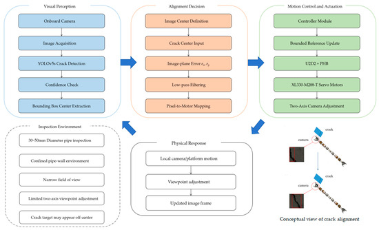
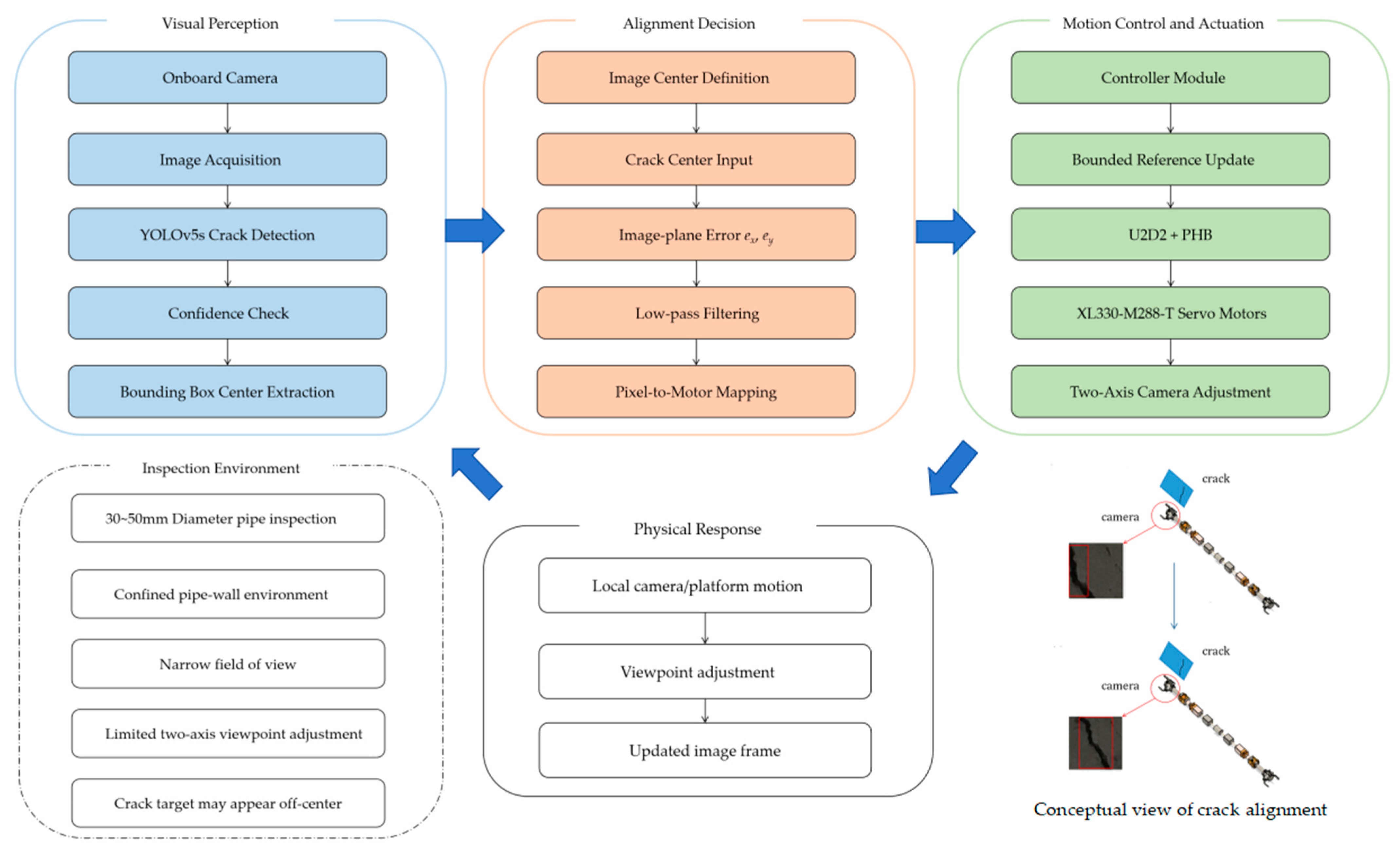
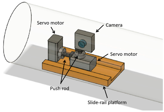
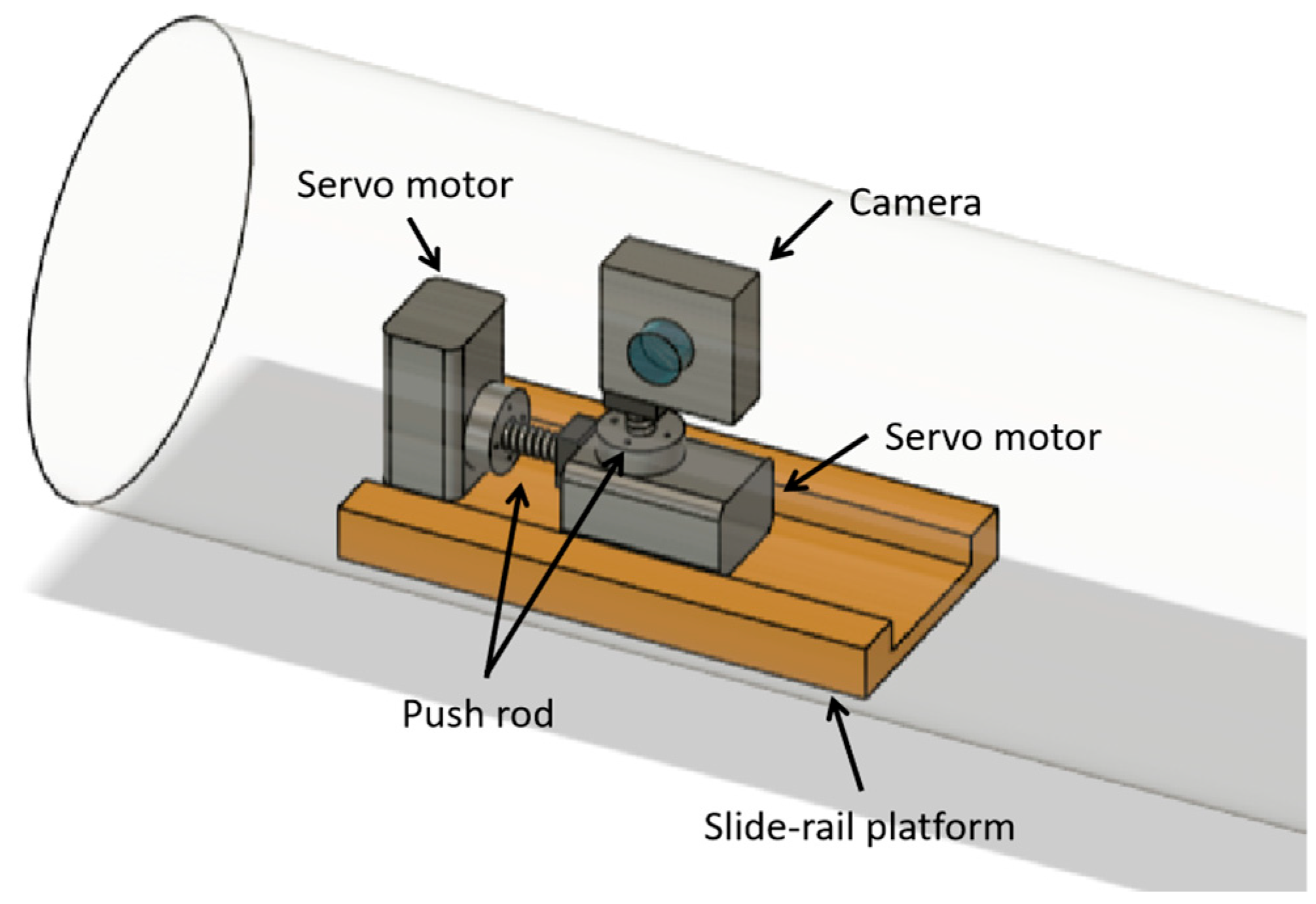
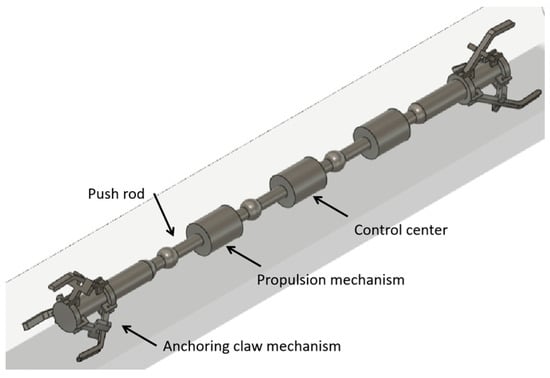
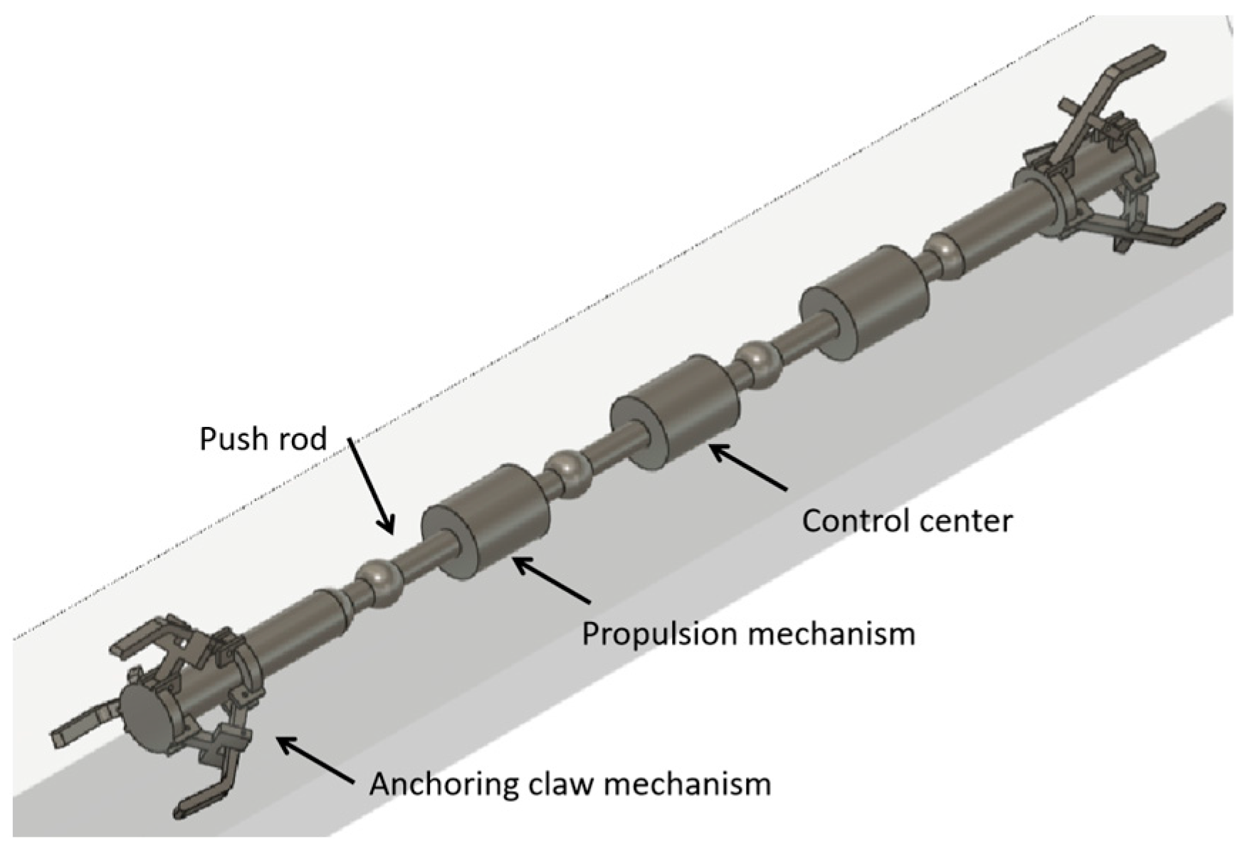
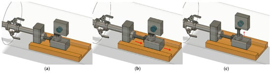
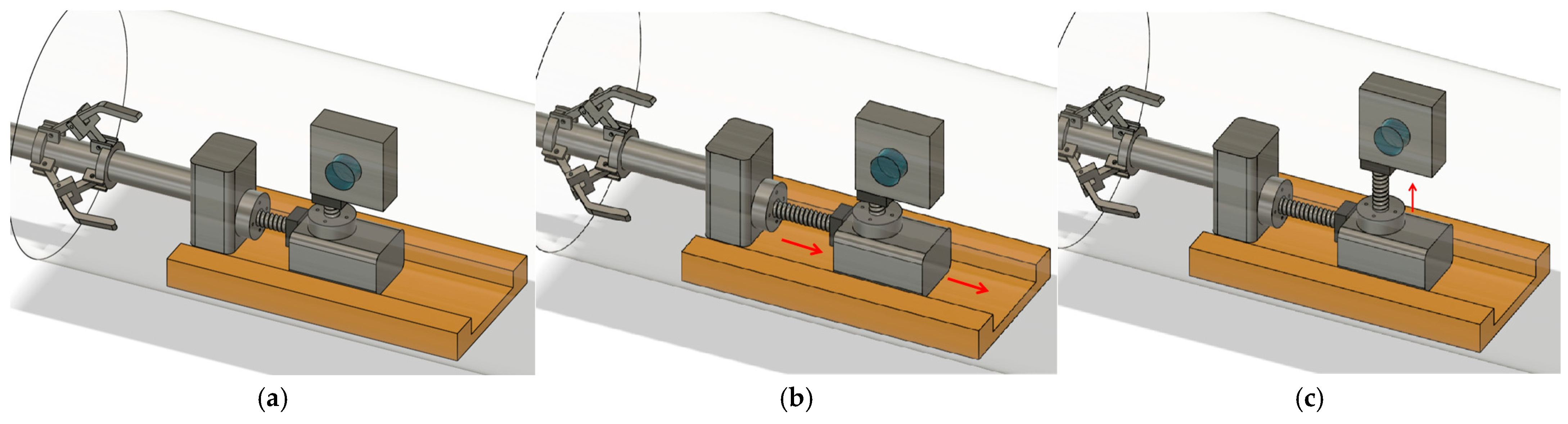
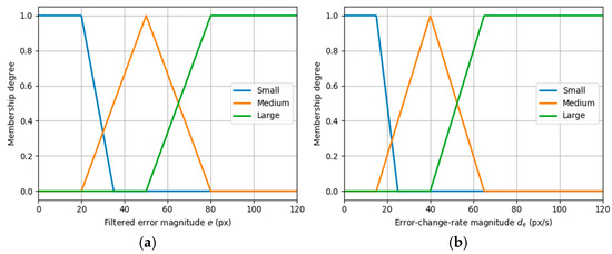
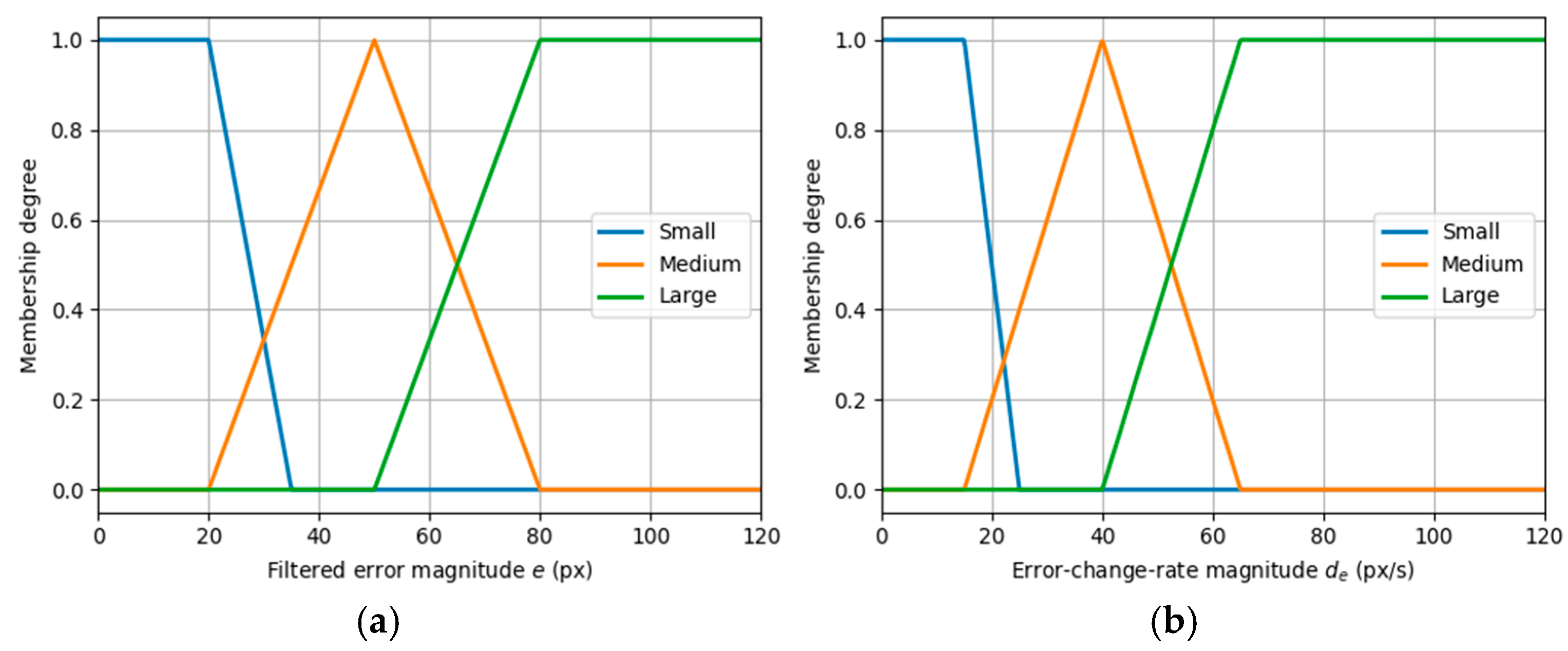
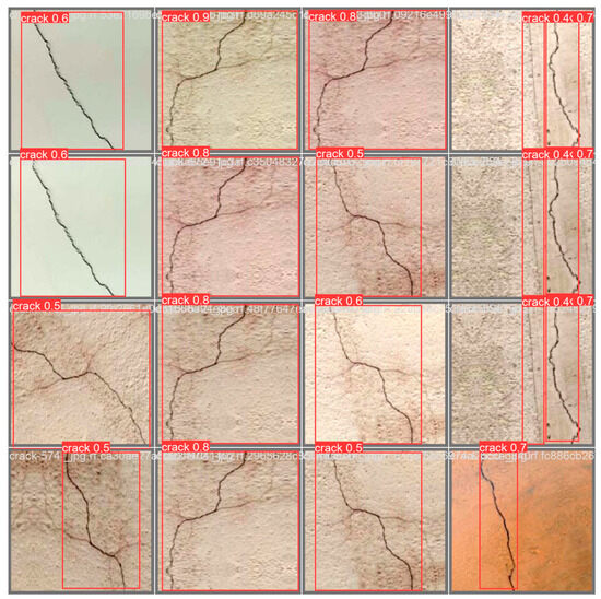
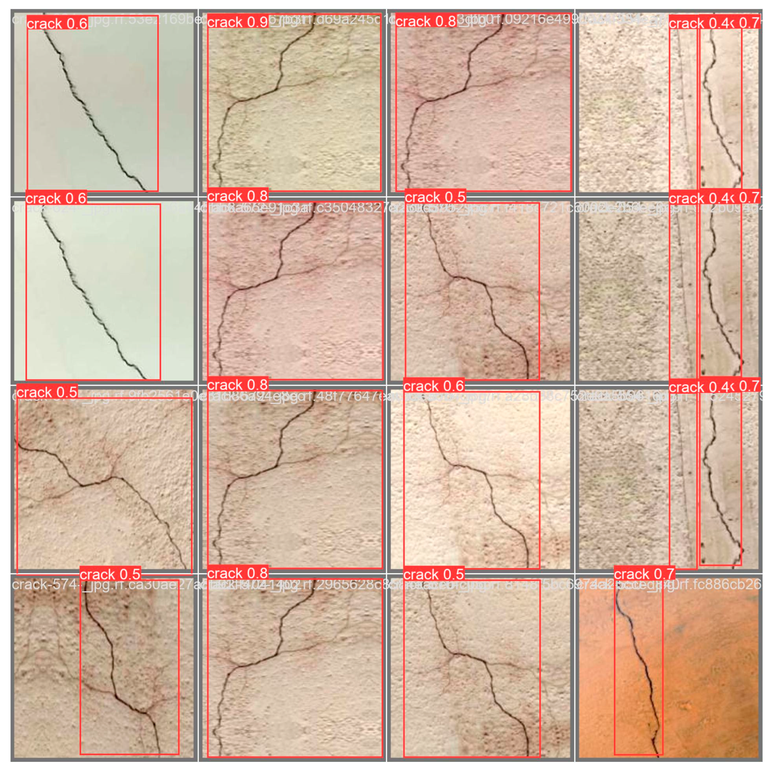
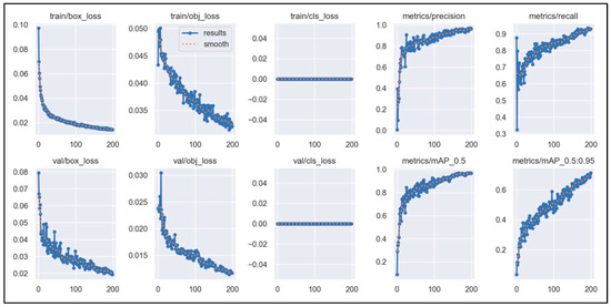
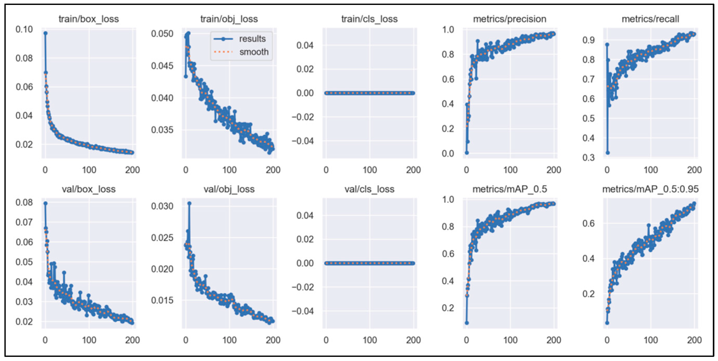
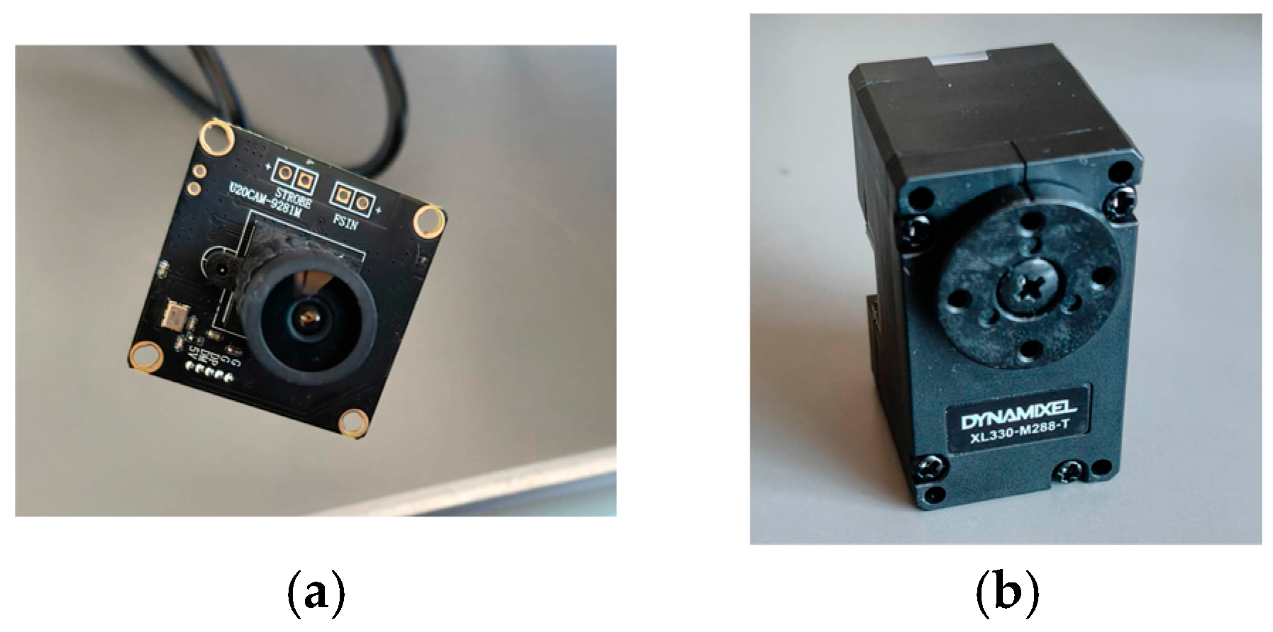
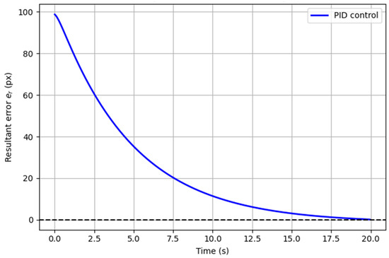
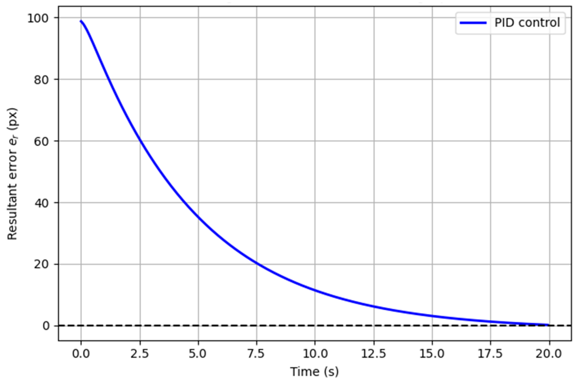
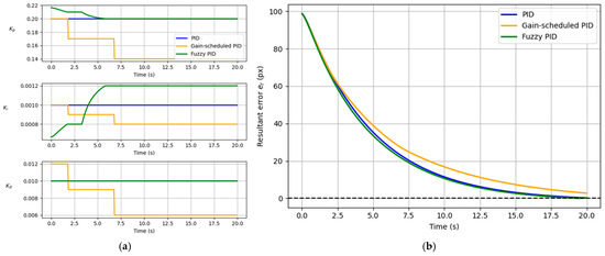
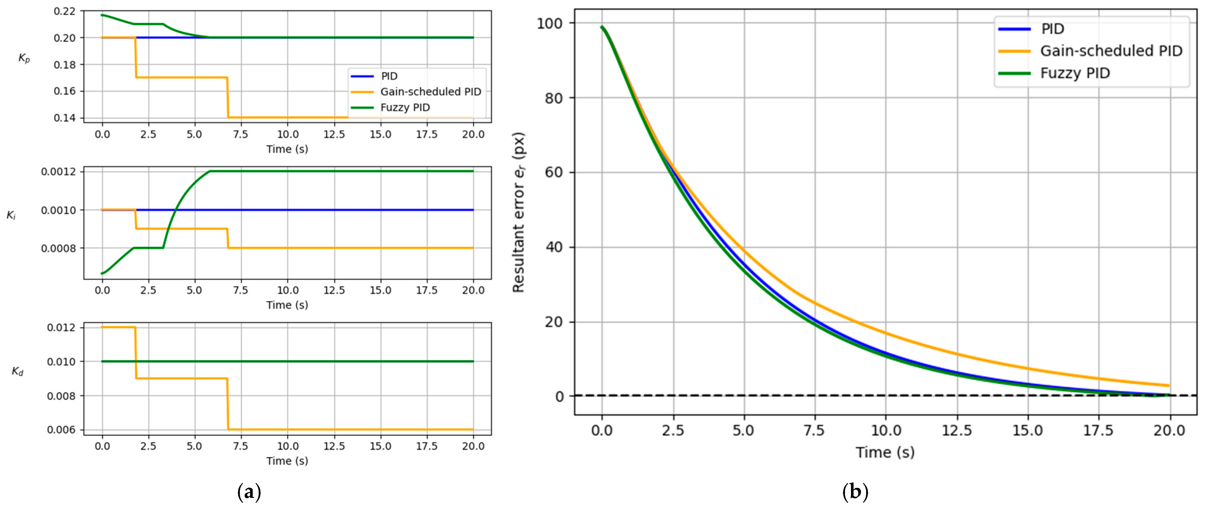
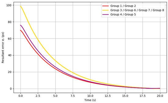
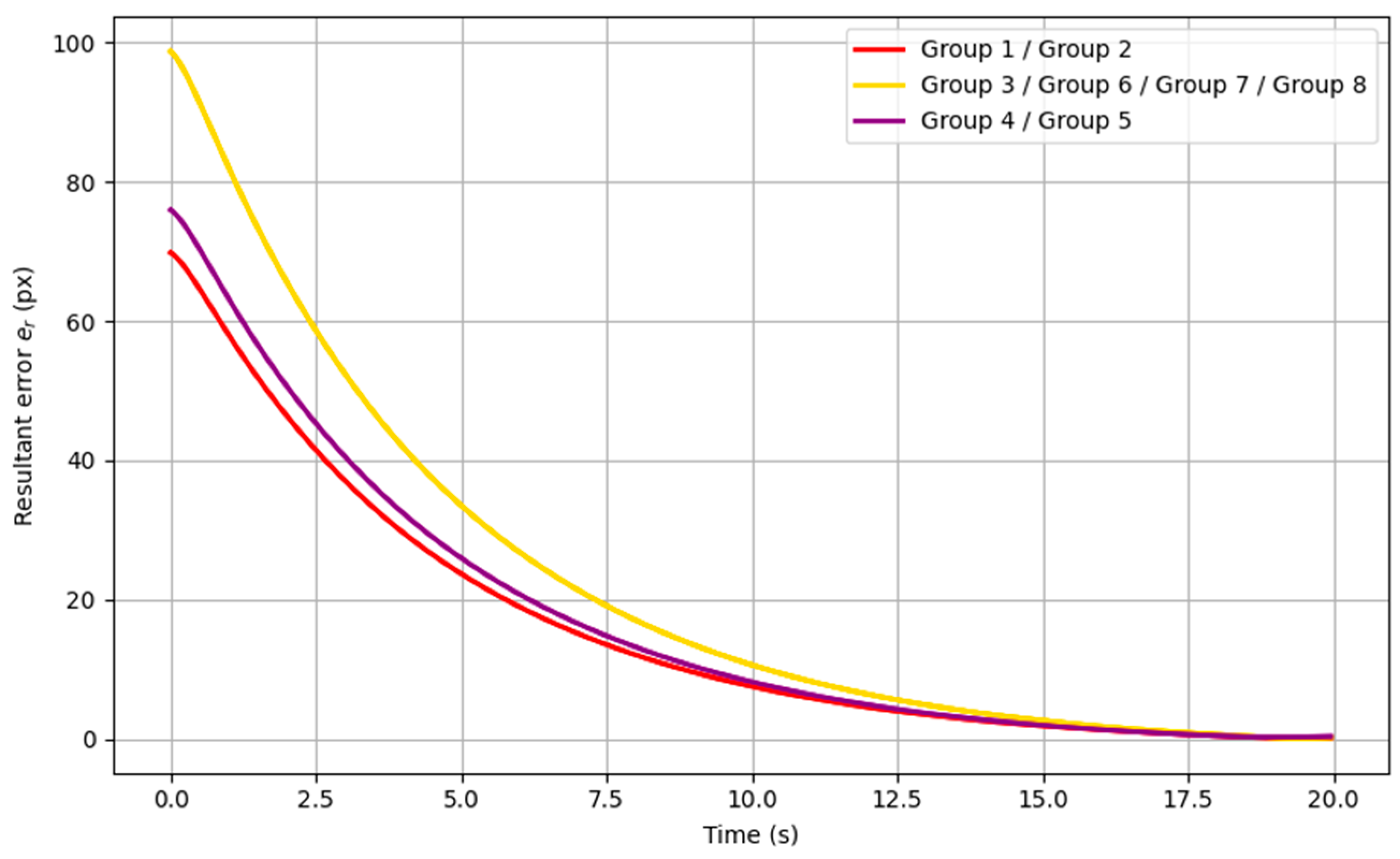
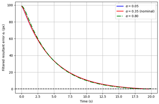
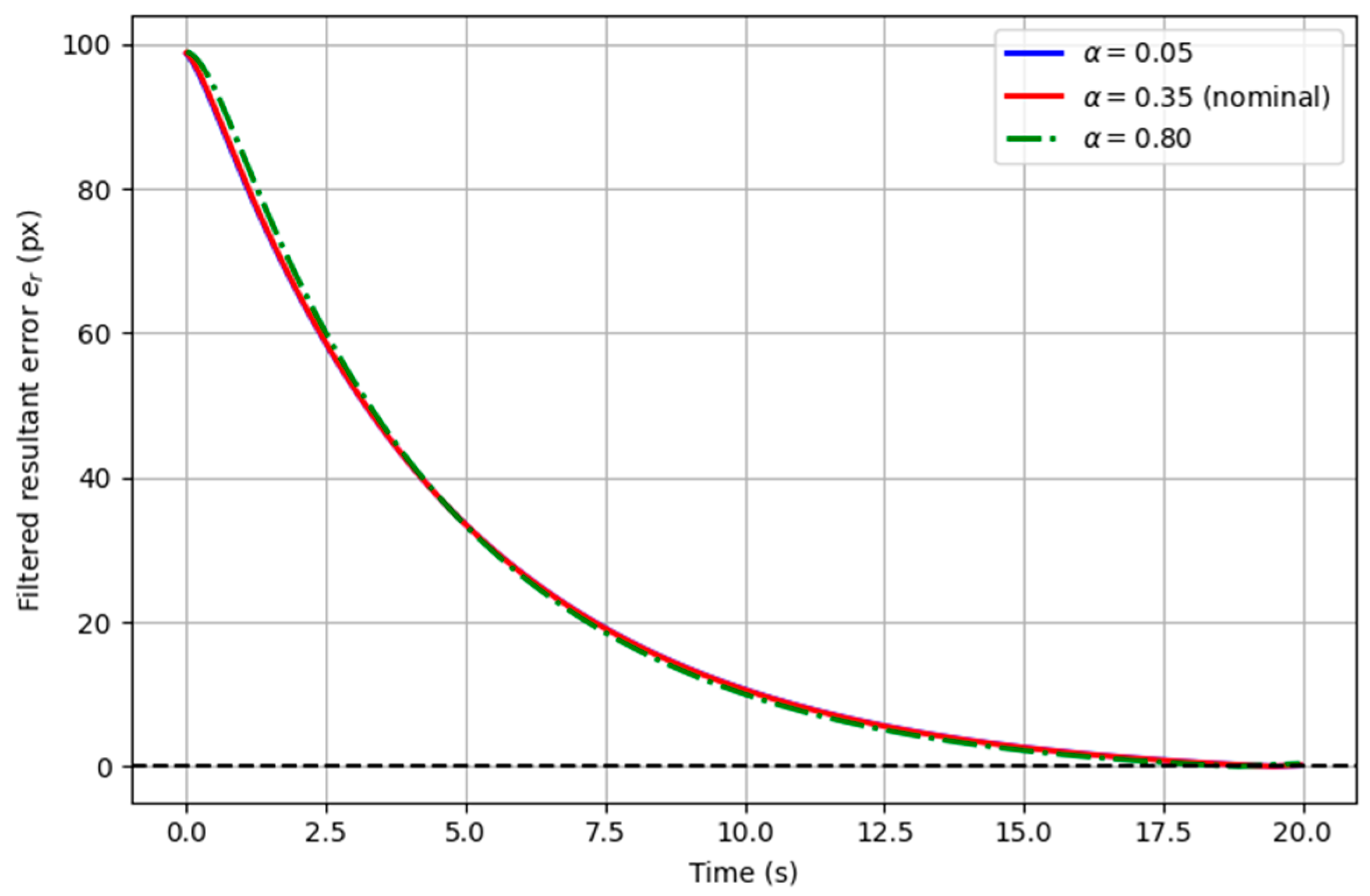
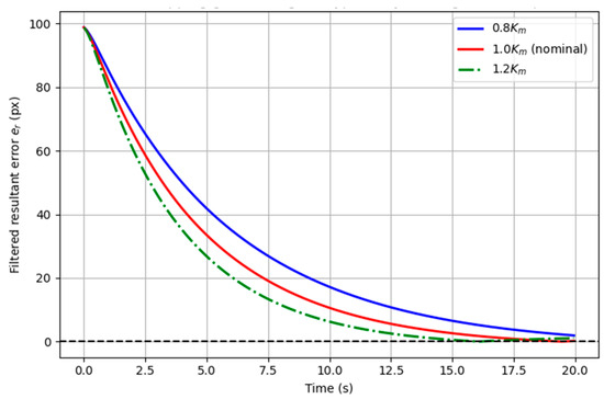
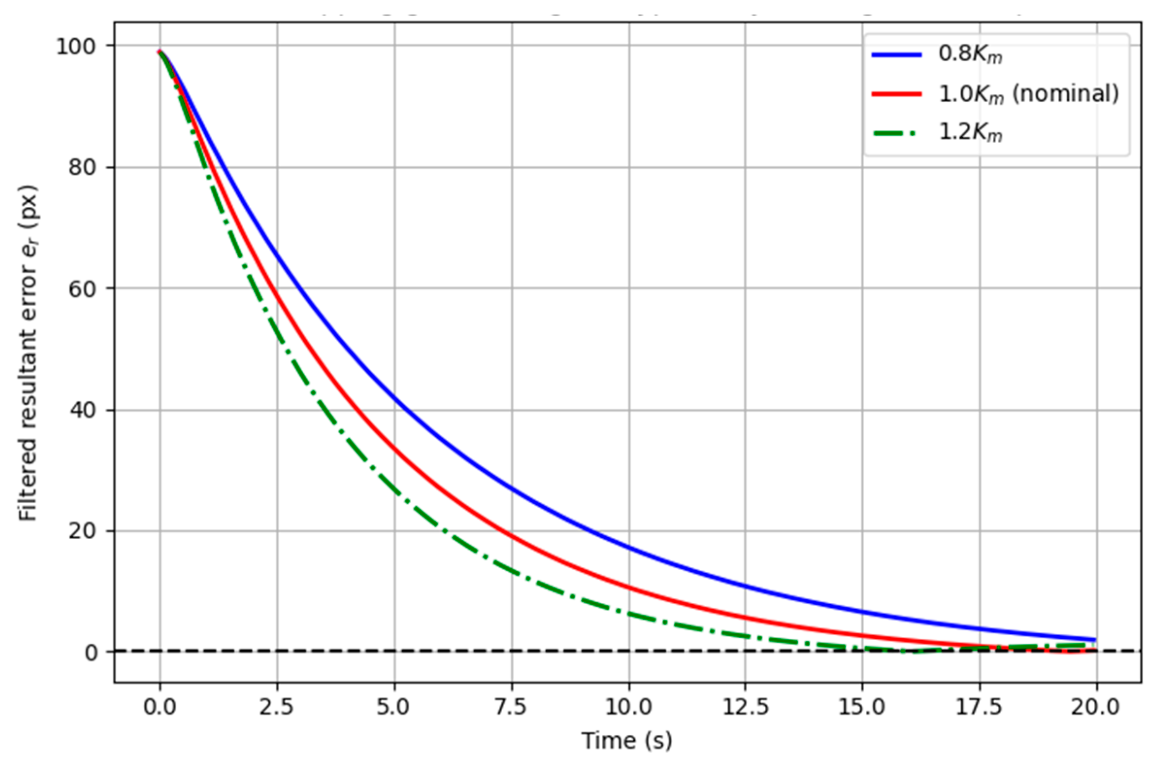
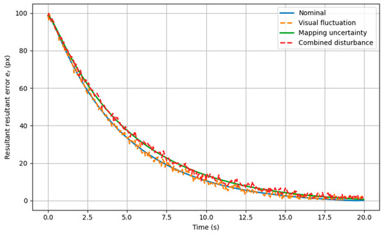
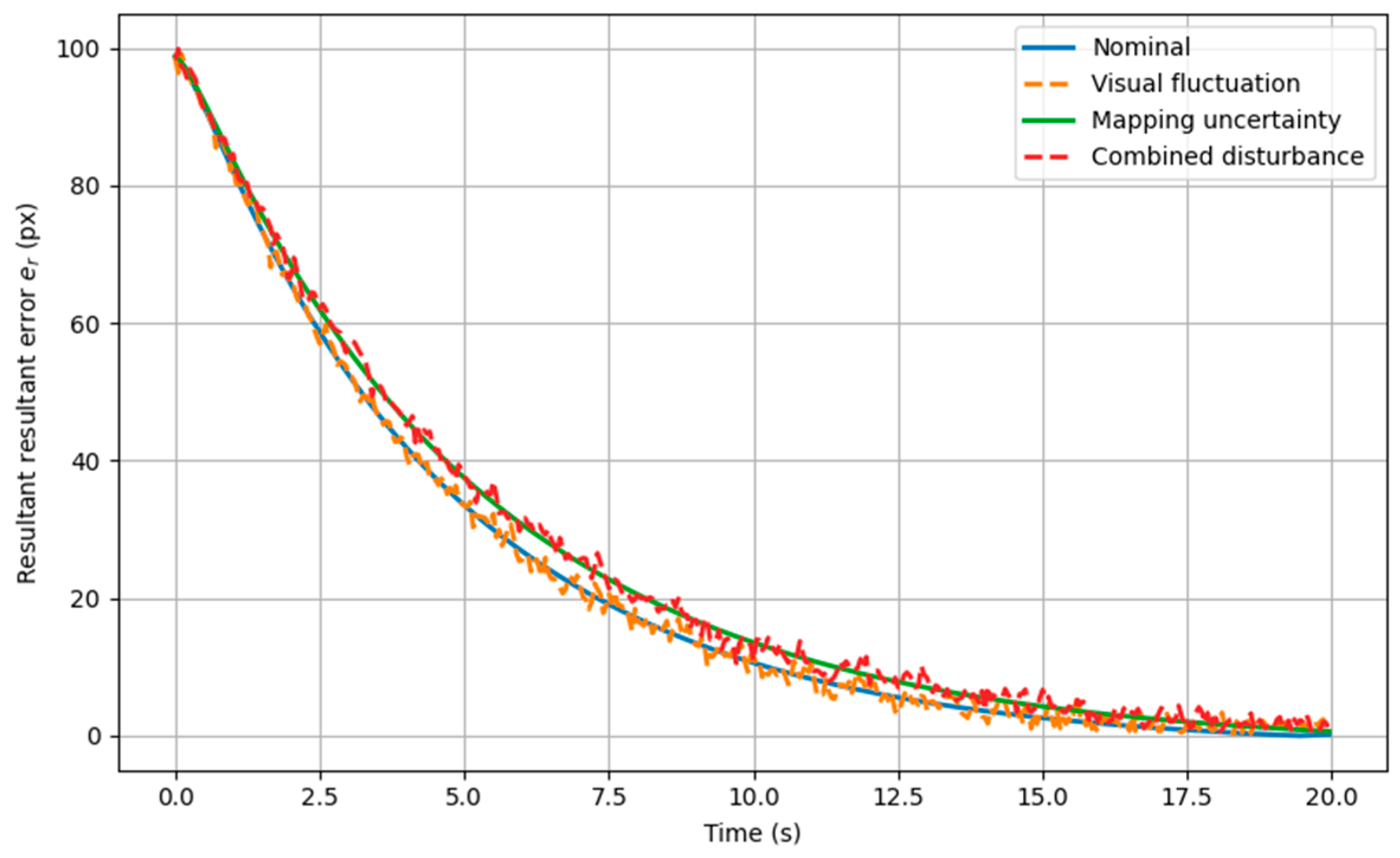
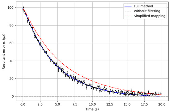
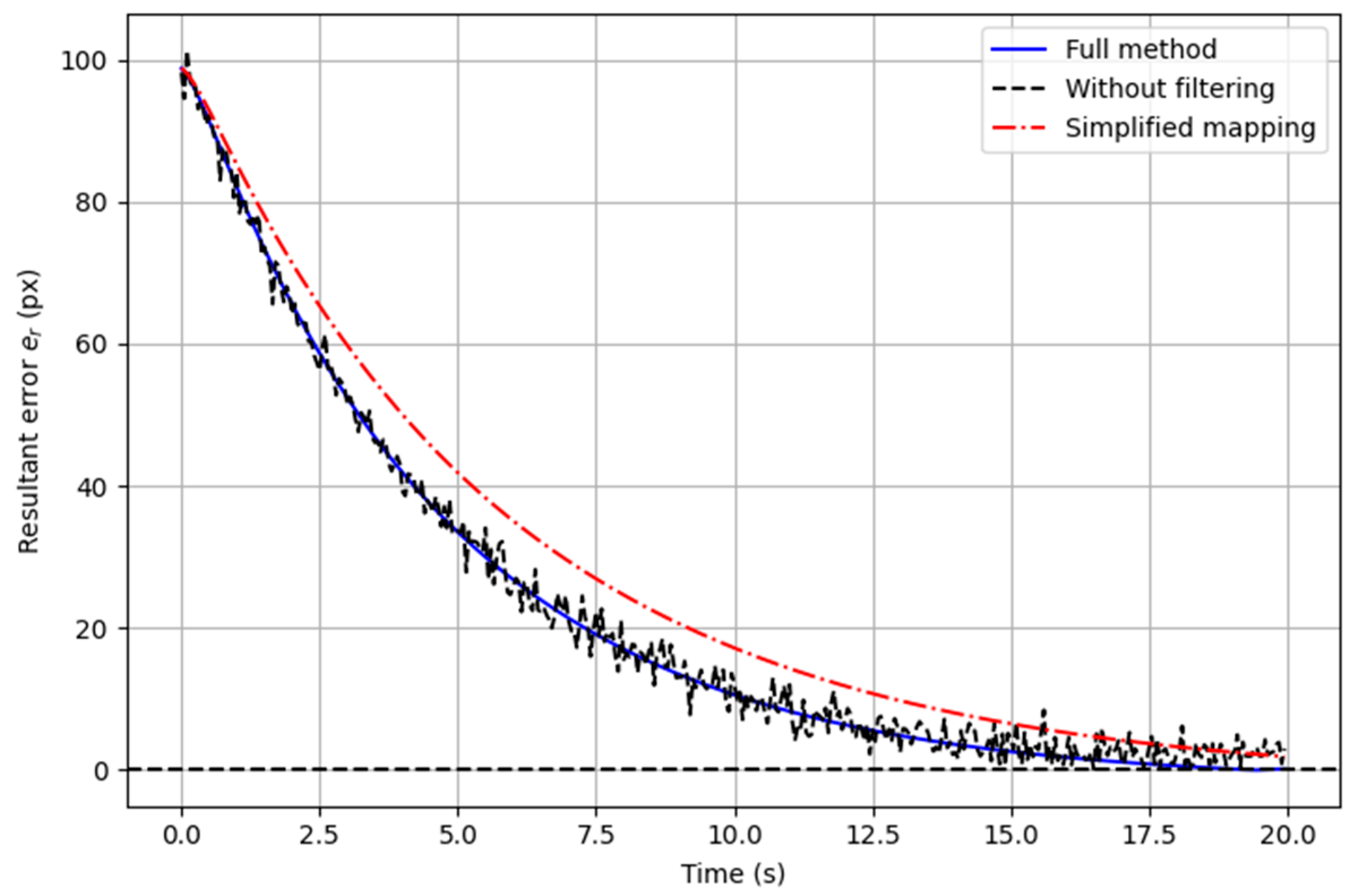
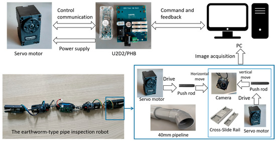
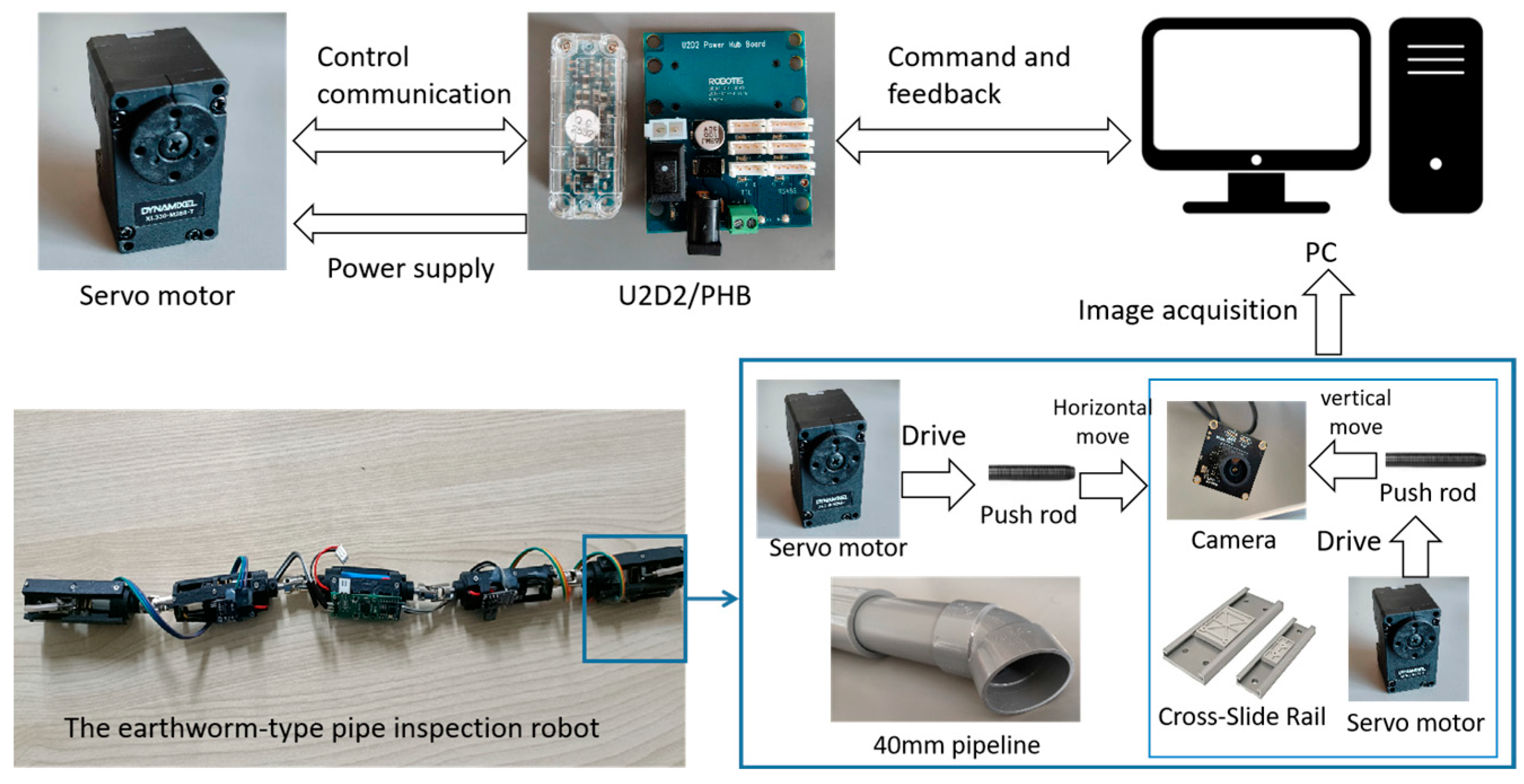
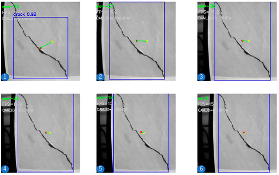
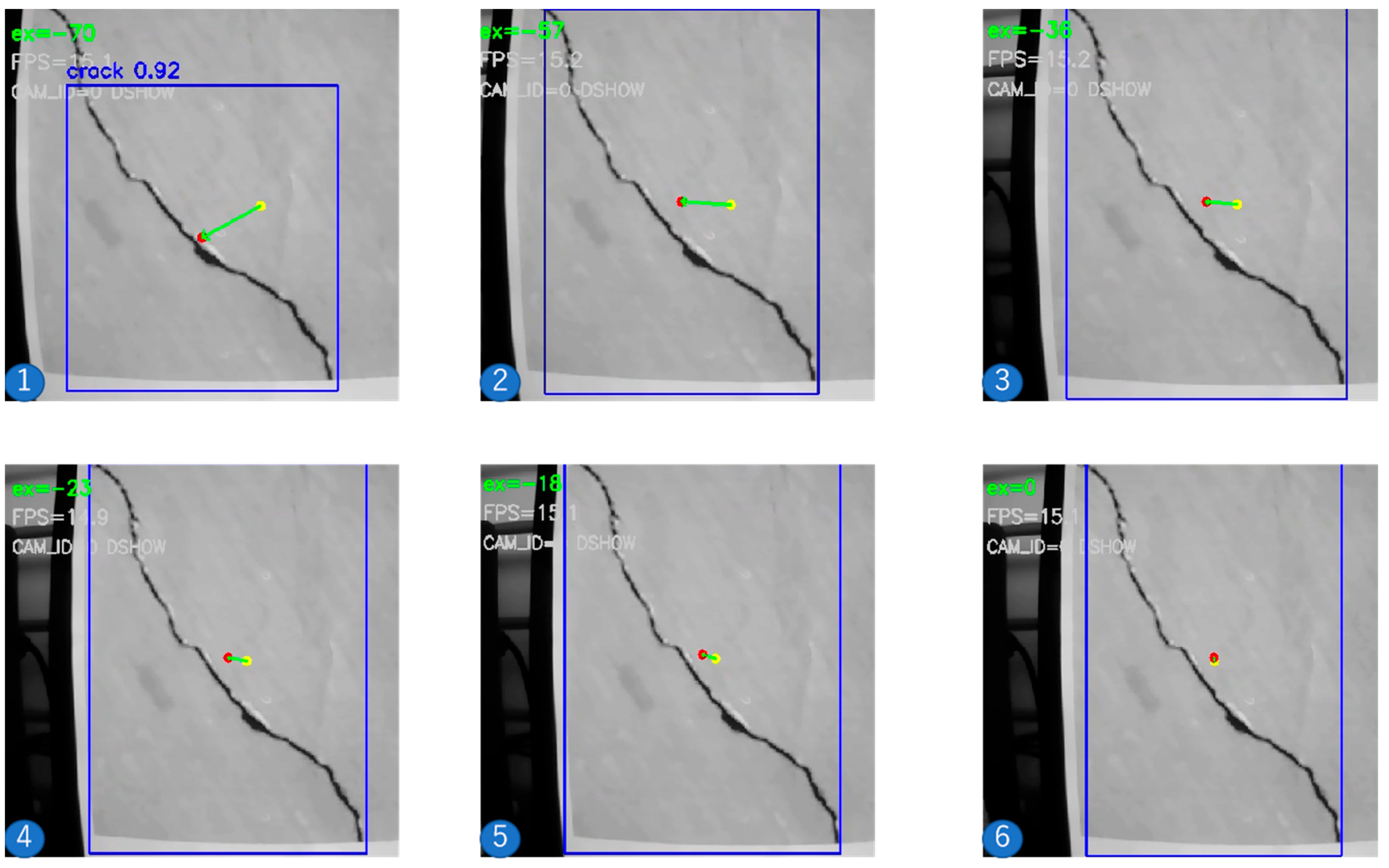
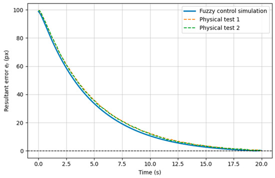
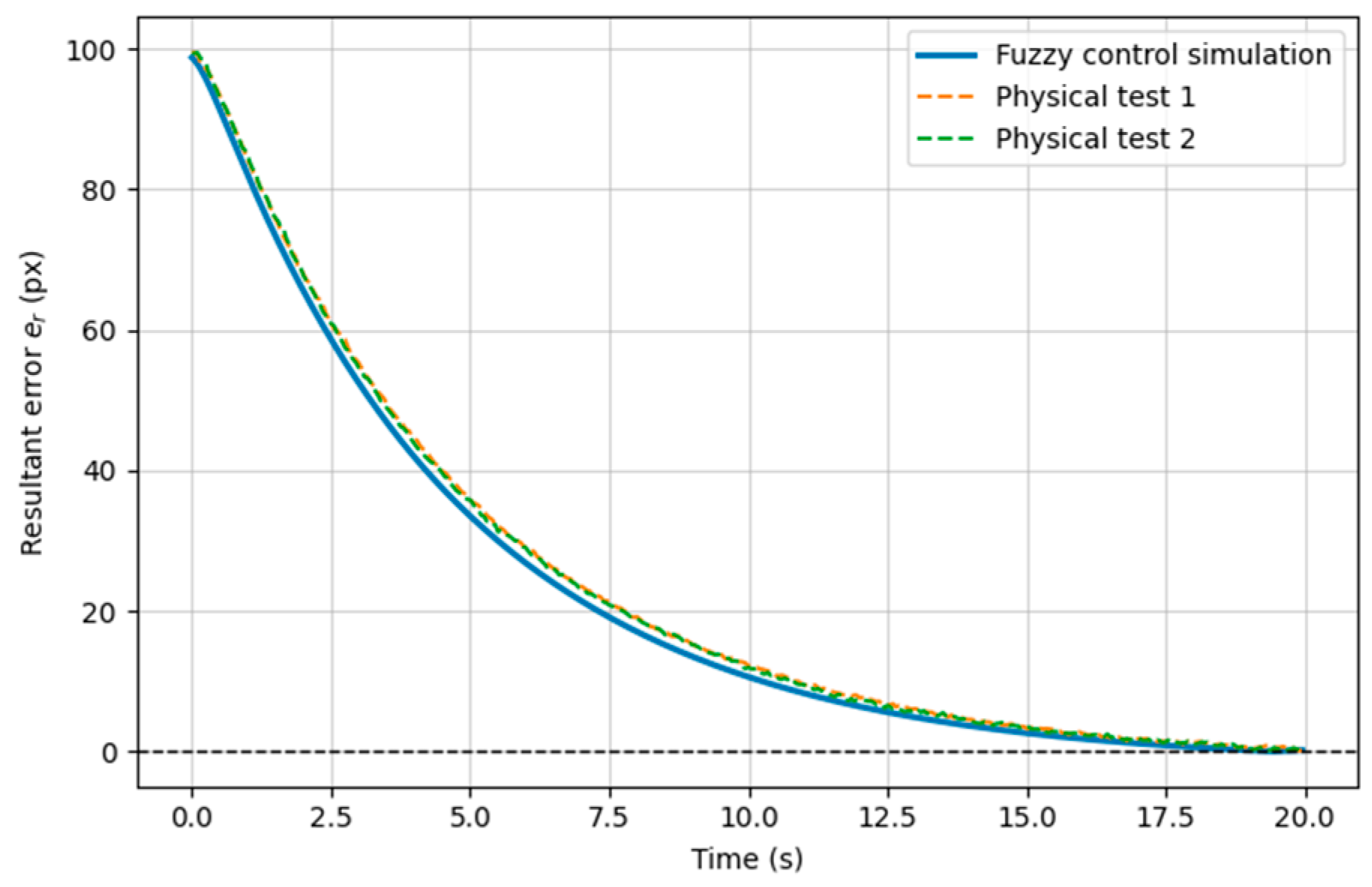

Disclaimer/Publisher’s Note: The statements, opinions and data contained in all publications are solely those of the individual author(s) and contributor(s) and not of MDPI and/or the editor(s). MDPI and/or the editor(s) disclaim responsibility for any injury to people or property resulting from any ideas, methods, instructions or products referred to in the content. |
© 2026 by the authors. Licensee MDPI, Basel, Switzerland. This article is an open access article distributed under the terms and conditions of the Creative Commons Attribution (CC BY) license.