


Abstract
This study presents experimental modal analysis of an ultra-lightweight composite structure representative of UAV application and to evaluate the suitability of different testing approaches for reliable identification of its dynamics characteristics. The investigated structure is a winglet made of carbon fiber reinforced polymer (CFRP) with a lightweight foam core. The experiment was based on impact hammer excitation combined with triaxial accelerometer measurements. Modal tests were performed under three different boundary conditions: free–free suspension using elastic cords, free–free approximation using compliant foam support, and fixed conditions reflecting the operational mounting of the winglet. The results confirm that boundary conditions constitute the dominant factor governing the dynamic response. Transition from free–free to fixed support shifted the dominant bending modal frequency from 331.5 Hz (single-sided response) and 329.9 Hz (double-sided response) 421.2 Hz in the fixed configuration, demonstrating a frequency increase of nearly 27%. Reciprocity and double-sided measurements revealed measurable frequency deviations (e.g., 116.3 Hz to 117.6 Hz) attributed to accelerometer mass loading and geometric misalignment. The 1 g triaxial accelerometer mass was shown to be non-negligible relative to the modal mass of the structure, producing observable shifts in higher-order modes.
1. Introduction
The proliferation of unmanned aerial vehicles (UAVs) marks a significant transition in modern transport. So-called drones extend their presence to military applications [1,2], large-area surveillance [3] and cargo delivery [4,5]. A key operational requirement for mini and small UAV platforms is maximizing flight endurance and operational range [6]. This requires usage of ultra-lightweight and structurally efficient materials. Consequently, advanced composites, particularly those based on carbon fiber (CFRP) have become the material of choice due to their superior strength-to-weight ratio and fatigue resistance compared to traditional metallic alloys [7]. To further optimize structural performance and increase bending stiffness while maintaining minimal mass, manufacturers frequently employ sandwich composite structures. These systems typically consist of high-stiffness CFRP face sheets separated by a lightweight, low-density foam core. These materials are widely used in components like winglets, which are essential devices added to the wingtips. These components primarily function by reducing induced drag and enhance the effective aspect ratio, thereby contributing directly to improved fuel efficiency and extended operational range [8]. As UAV structures continue to decrease in mass and structural stiffness, their dynamic behavior becomes an increasingly critical design consideration. Lightweight composite components are inherently more susceptible to vibration-related phenomena, including aeroelastic instabilities such as flutter. Reliable identification of their modal properties is therefore a prerequisite for any credible dynamic or aeroelastic assessment, particularly in the early stages of design, where simplified analytical or low-order numerical models are commonly employed [9].
Maharudra et al. [10] investigated the vibration behavior of laminated composite panels with varying thickness and boundary conditions using a higher-order shear deformation theory. Their results showed that boundary conditions have a significant influence on natural frequencies for thin plate configurations, whereas this effect becomes negligible for thick plates. Their study was conducted through numerical simulations. Guo et al. [11] investigated the effect of boundary conditions on the vibration characteristics of sandwich plates with periodic cores using a theoretical and finite element approach. They showed that varying the stiffness of boundary constraints influences the vibration band structure and band-gap characteristics of the plate. Erkliğ et al. [12] analyzed the influence of boundary conditions on the free vibration and damping characteristics of hybrid laminated composite plates composed of carbon, Kevlar and S-glass fibers. Their experimental and finite element results revealed that boundary constraints significantly affect both natural frequencies and damping behavior, with distinct differences observed between clamped, simply supported and free-edge configurations. The study employed experimental modal testing based on impact hammer excitation and accelerometer response measurements. Qu et al. [13] investigated modal testing methods for honeycomb sandwich panels subjected to conditions relevant for aerospace applications, such as noise loads and elevated temperatures. Four excitation approaches were compared: impact hammer excitation, transient excitation, pulse sequence excitation, and random noise excitation. The study demonstrated that all four methods can provide effective modal measurement results. The experimental campaign was conducted on sandwich specimens of relatively large dimensions and mass, and the primary focus was placed on high-temperature testing conditions. Karpenko et al. [14] examined the modal response of extruded polystyrene foam embedded in composite panels, combining experimental micro-vibration measurements with finite element simulations. The study highlighted low-frequency resonances and confirmed close agreement between numerical and experimental results, emphasizing the importance of accurately characterizing lightweight materials for dynamic and aeroelastic assessments in small aircraft structures. During the experiment, a piezoelectric micro-actuator was used to excite controlled vibrations in XPS samples, while the dynamic surface response was captured using a laser scanning vibrometer. Zhang et al. [15] conducted an experimental and numerical investigation of the thermal–vibration behavior of lattice-structured air rudders subjected to combined thermal gradients and dynamic excitation. Modal characteristics under elevated temperatures were identified using non-contact scanning laser Doppler vibrometry with usage of an electromagnetic vibrator to excite the structure. Qaumi and Hashemi [16] performed combined experimental and numerical modal analyses of an experimental rocket aerostructure in order to assess and calibrate finite element models used in the design process. Excitation was provided by a hammer tap test, and the structural response was measured using laser Doppler vibrometers. Chuang and Kim [17] investigated the influence of uniaxial static loading on the dynamic behavior of unidirectional carbon-based composite (UCBC) structures. Their study demonstrated that static preload can significantly modify modal parameters. Uniaxial accelerometers were attached to the specimens, and excitation was provided using a modal impact hammer.
A similar sensitivity for dynamic behaviour has also been reported in the automotive sector for ultra-lightweight sandwich composite structures [18]. In a recent investigation of a photovoltaic roof for a solar racing vehicle, a large composite sandwich panel was analysed under free–free, constrained and pre-loaded conditions. The study demonstrated that gravity effects, constraint modelling and additional mass contributions significantly influenced the identified natural frequencies and modal mass participation, despite the structure being primarily designed for stiffness-to-weight optimization.
Although the cited studies provide valuable insight into the vibration behavior of composite and sandwich structures, the majority focus either on numerical simulations or on laboratory-scale specimens characterized by relatively high mass and stiffness. Systematic experimental investigations addressing the reliability of modal testing in ultra-lightweight aerospace components remain limited. In particular, the combined influence of support compliance, excitation strategy, and accelerometer mass loading on the identified modal parameters of very low-mass sandwich elements has not been comprehensively quantified.
Despite the extensive range of materials, structural configurations, and testing approaches reported in the literature, no unified guidelines exist for experimental modal analysis of ultra-lightweight composite components used in mini and micro UAVs. Previous studies have explored various boundary conditions and measurement systems; however, the sensitivity of identified modal characteristics to realistic support configurations in extremely low-mass structures remains largely unaddressed.
This issue becomes especially critical for externally mounted components such as winglets, which are located at the wingtip where bending and torsional deformation amplitudes reach their maximum. Due to their position at the end of the lifting surface, winglets can significantly influence the global dynamic behavior of the wing through their mass distribution, stiffness contribution, and aerodynamic interaction. Even minor variations in attachment compliance or local stiffness may result in measurable shifts of modal properties within frequency ranges relevant to aeroelastic stability.
The present study advances existing research by addressing three key aspects that are often neglected in experimental modal analyses of ultra-lightweight composite UAV components. First, roving accelerometer measurements were conducted on both sides of the winglet to capture full 3D mode shapes, providing a more complete representation of structural dynamics. Second, the influence of measurement-induced mass loading on the identified modal parameters was systematically evaluated, ensuring that the extremely low mass of the winglet does not compromise the accuracy of the results. Third, multiple support conditions—including elastic cord and compliant foam free–free suspensions, as well as rigidly fixed clamping—were compared to quantify their impact on modal frequencies, mode shapes, and effective mass participation. By combining these elements, this work provides practical guidance for reliable modal testing and sets a benchmark for experimental characterization of ultra-lightweight sandwich structures relevant to aeroelastic and flutter assessments.
2. Materials and Methods
The study is based on experimental vibration testing conducted to characterize the dynamic response of a composite winglet used in a mini-UAV platform. The component is manufactured as a sandwich structure with carbon fiber skins and a lightweight foam core, which results in a stiff but low-mass configuration typical for small, unmanned aircraft. Due to the low mass and high compliance of such thin-walled composite assemblies, their dynamic response is highly sensitive to boundary conditions, excitation methods and measurement-induced mass-loading effects.
2.1. Design of the Winglet
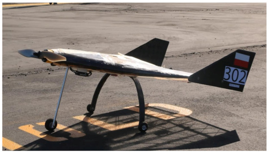
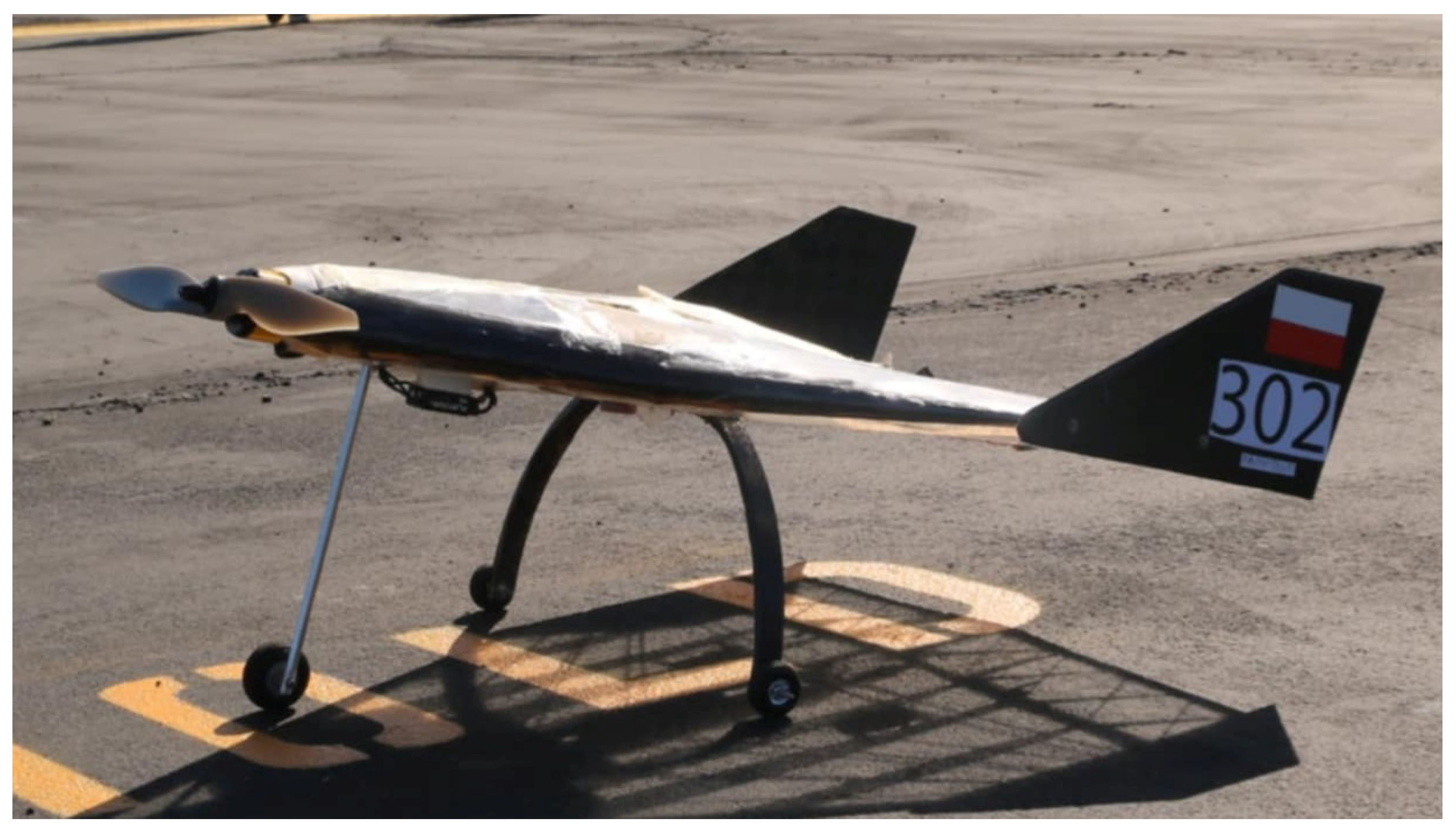
The winglet examined in this study is part of a micro-class UAV (Figure 1) designed by the team from Wrocław University of Science and Technology for the SAE Aero Design 2024 competition [19]. The aircraft follows a flying-wing configuration with a highly swept, delta-type planform, resulting in a wingspan of 0.6 m and an empty mass of approximately 1.5 kg, fully complying with the dimensional limitations defined in the SAE ruleset. A key advantage of delta wings is the sustained attachment of the flow over the wing surface at high angles of attack, which postpones stall onset and leads to improved lift characteristics and overall aerodynamic performance [20].
Figure 1.
Micro-class UAV designed by the Wrocław University of Science Technology student team for SAE Aero Design 2024.
In the micro category, aerodynamic efficiency is a key performance factor due to the strict take-off and payload constraints. For this reason, small tip devices were incorporated into the design to mitigate wingtip vortex formation and improve overall lift-to-drag characteristics. In addition, the winglet contributes to the control of leading-edge vortex development by limiting outward convection towards the wingtip, thereby promoting a more effective utilization of the lifting surface. The composite winglet analysis in the present work is one of these components and serves as an externally mounted aerodynamic extension at the wingtip.
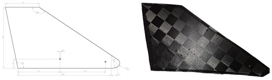
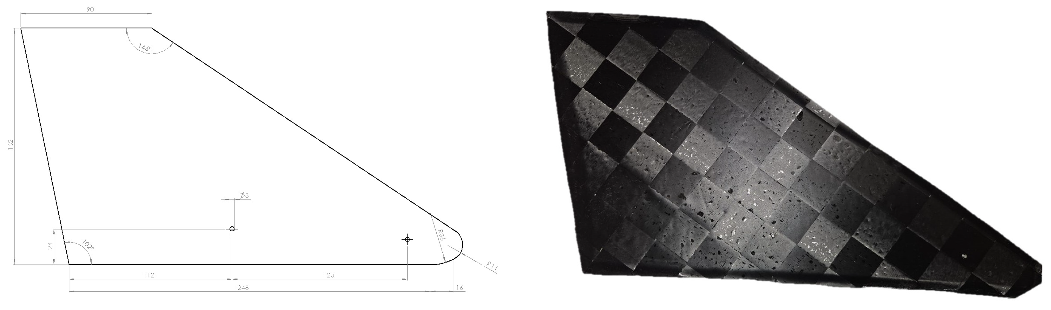
The geometric layout as well as the physical model of the winglet is presented in Figure 2, showing all relevant dimensions. This component was designed to enhance aerodynamic performance by reducing drag and improving directional stability at the wingtips, and providing a secondary contribution to lift through the modification of local flow structures. While these design choices were made to optimize flight efficiency, the present study focuses exclusively on the dynamic characteristics of the winglet itself. Consequently, the discussion does not elaborate further on the aerodynamic rationale or detailed geometric optimization, as these aspects are outside the scope of this work. The wingtip is mounted to the wing using screws inserted through the 2 holes indicated in Figure 2.
Figure 2.
Geometry of the winglet. All dimensions in millimeters.
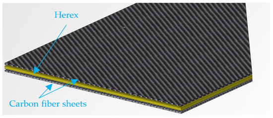
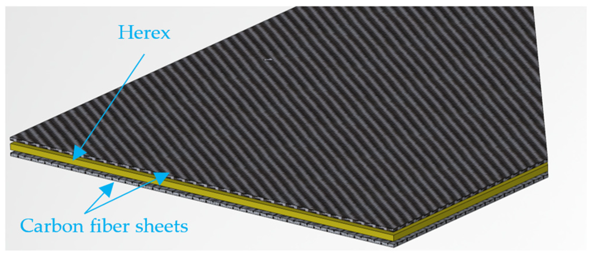
The winglet is constructed as a sandwich structure, consisting of CFRP face sheets made from Aspro spread tow A-80 fabric arranged in a ±45° lay-up and a 2 mm Herex foam core (Figure 3). The CFRP skins provide high bending stiffness and strength, while the foam core maintains the shape and contributes to overall structural rigidity with minimal mass. The component was manufactured using a combination of hand lay-up for the CFRP layers and vacuum bagging techniques to consolidate the sandwich assembly. The winglet weight is 14 g. This manufacturing approach was selected to ensure repeatable laminate quality suitable for lightweight UAV structures. The material properties of the CFRP skins and the foam core are summarized in Table 1 and were taken from previous experimental characterization and validated reference data.
Figure 3.
Sandwich structure of the winglet studied in this work.
Table 1.
Material properties based on previous work [21].
2.2. Experimental Campaign
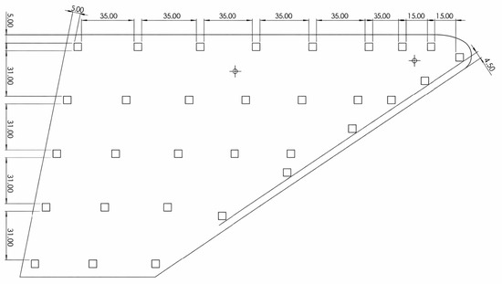
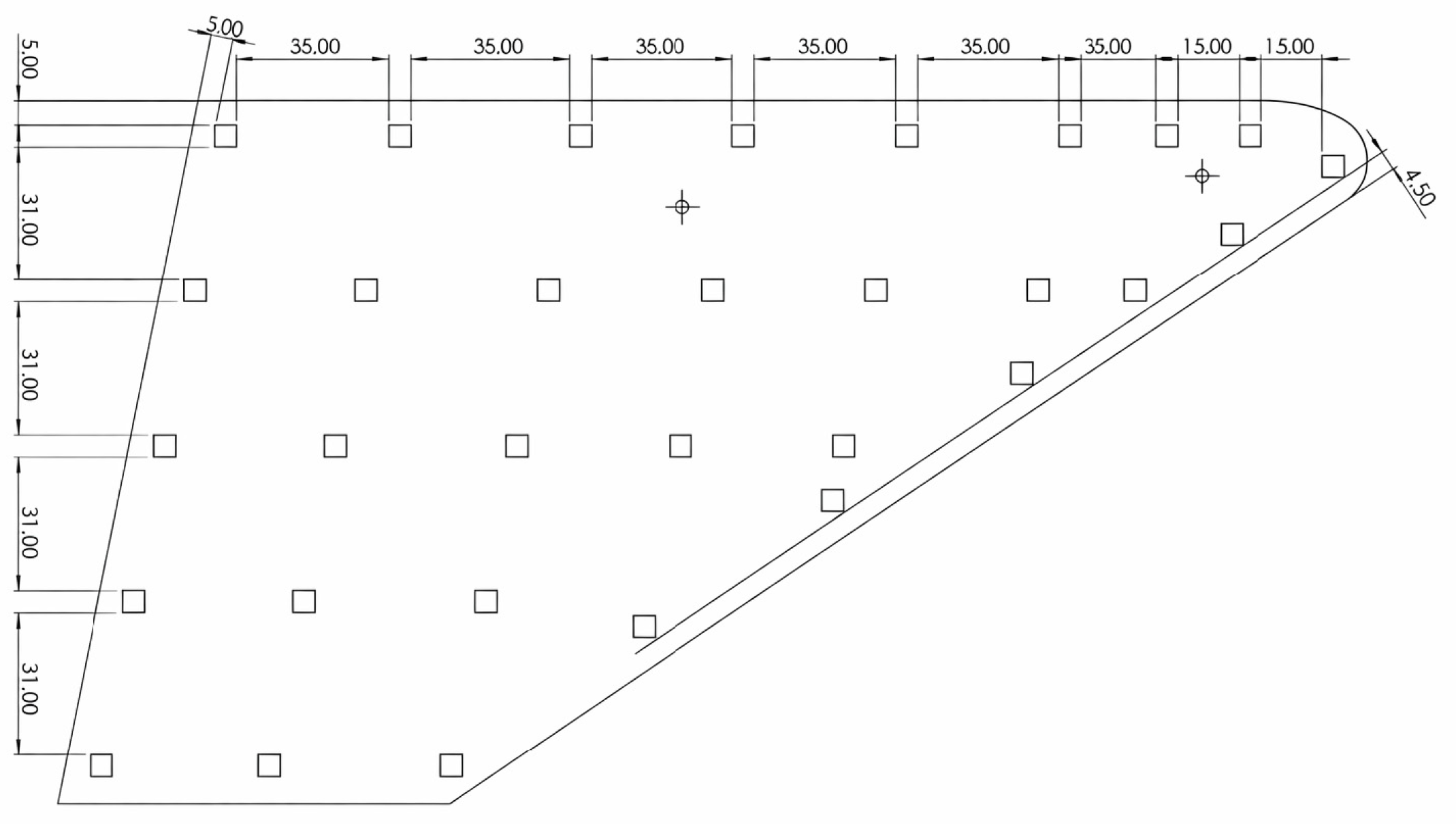
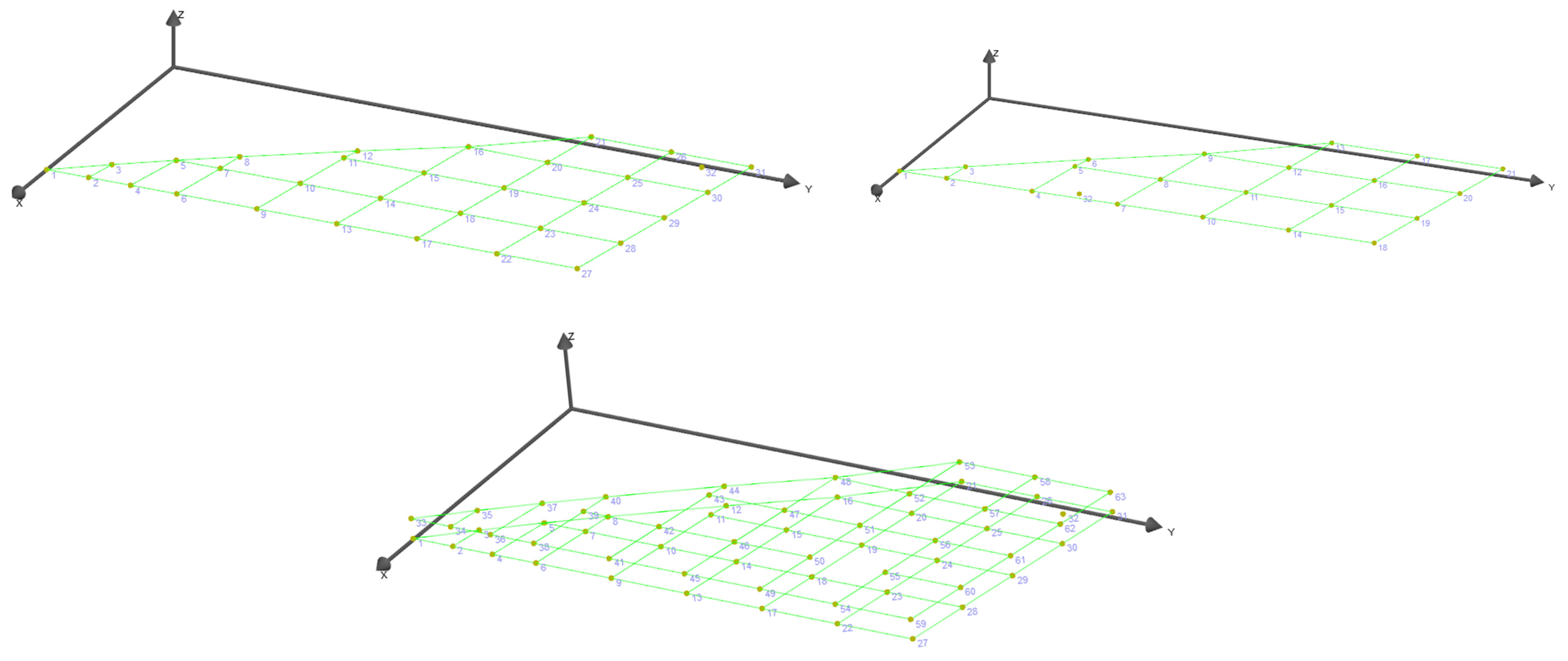
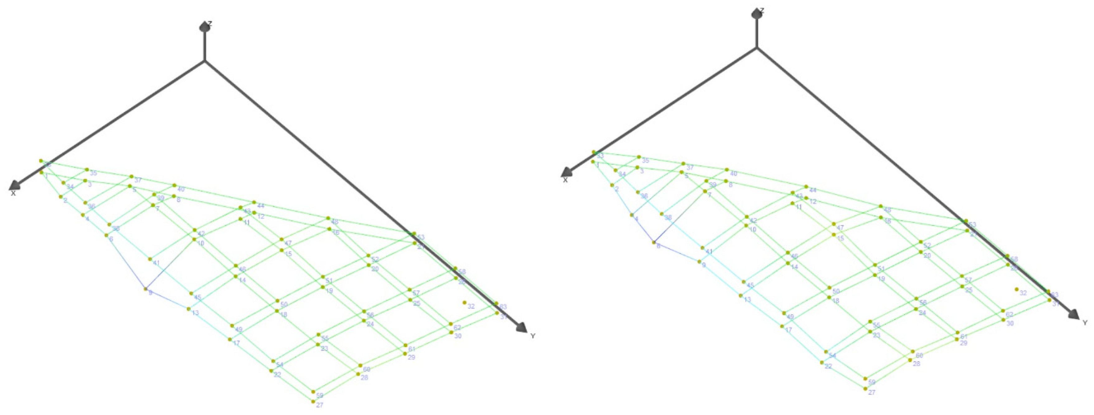
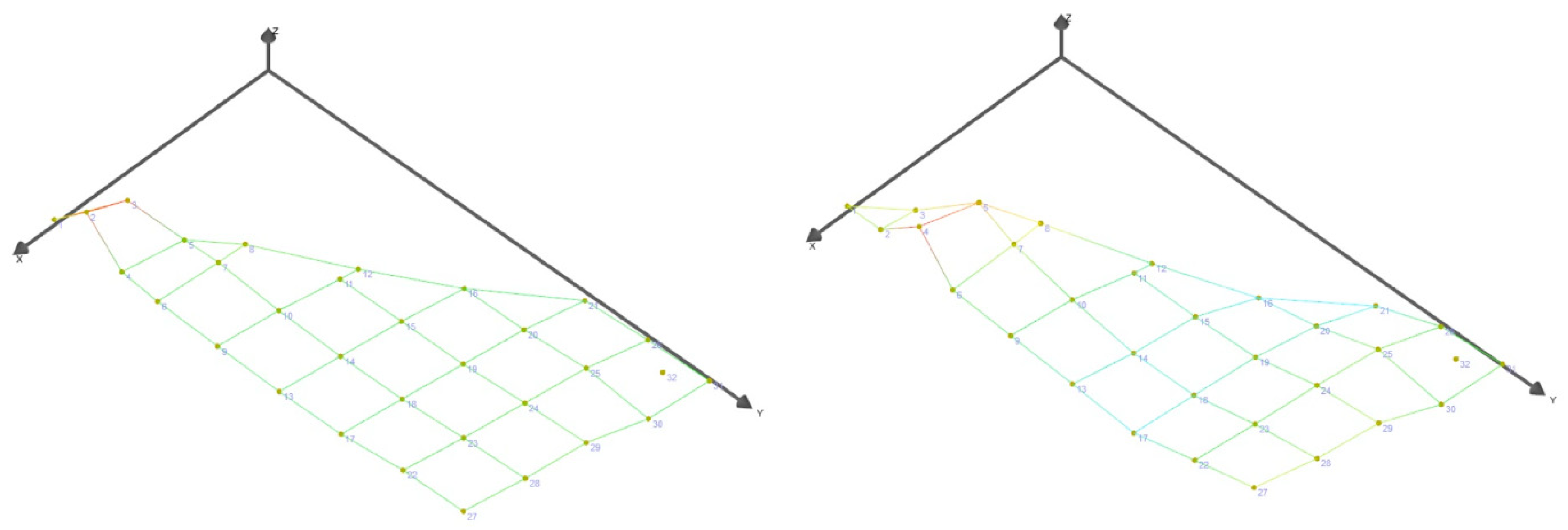
The experimental investigation was structured as a series of modal tests conducted under three different boundary condition configurations in order to assess their influence on the identified dynamic characteristics of a lightweight composite winglet. Due to the sandwich configuration of the structure (CFRP–Herex–CFRP), an additional measurement procedure was incorporated into the experimental campaign. In this procedure, response points were placed on both sides of the winglet (i.e., on each CFRP face sheet) to enable detailed assessment of the natural frequencies, global and local mode shapes, and the corresponding modal displacements. The measurement points shown in Figure 4 and Figure 5 were mirrored on the opposite side of the winglet to permit direct, point-to-point comparison between the two outer skins. The actual distance between the two measurement surfaces presented in Figure 5 was defined by the thickness of the test sample; however, to improve the quality of presentation, the distance between the two sides of the test surfaces was scaled in the modal geometry model.
Figure 4.
Measurements points. All dimensions in millimeters.
Figure 5.
Measurement points located on one side and on both sides of the winglet.
The approach presented above applies for sandwich structures, as the two CFRP face sheets may exhibit out-of-phase motion in some mode shapes, especially at higher frequencies where the mode shape is more complex. An antisymmetric response of the two face sheets cannot be detected if measurements are taken only at one side of the structure. Measurements on both sides of the composite should provide more information on the vibrational behavior of the composite sandwich and allow for accurate identification of both global and local sheet modal phenomena. A comparison between the results obtained from the single-sided and double-sided analyses should highlight the potential practical implications and inform directions for future work.
Consideration of the previously discussed testing approaches should reflect the practical challenges encountered during modal testing of low-mass sandwich structures and provide a basis for formulating recommendations regarding suitable testing configurations for UAV components.
2.3. Free–Free Suspension Using Elastic Cords
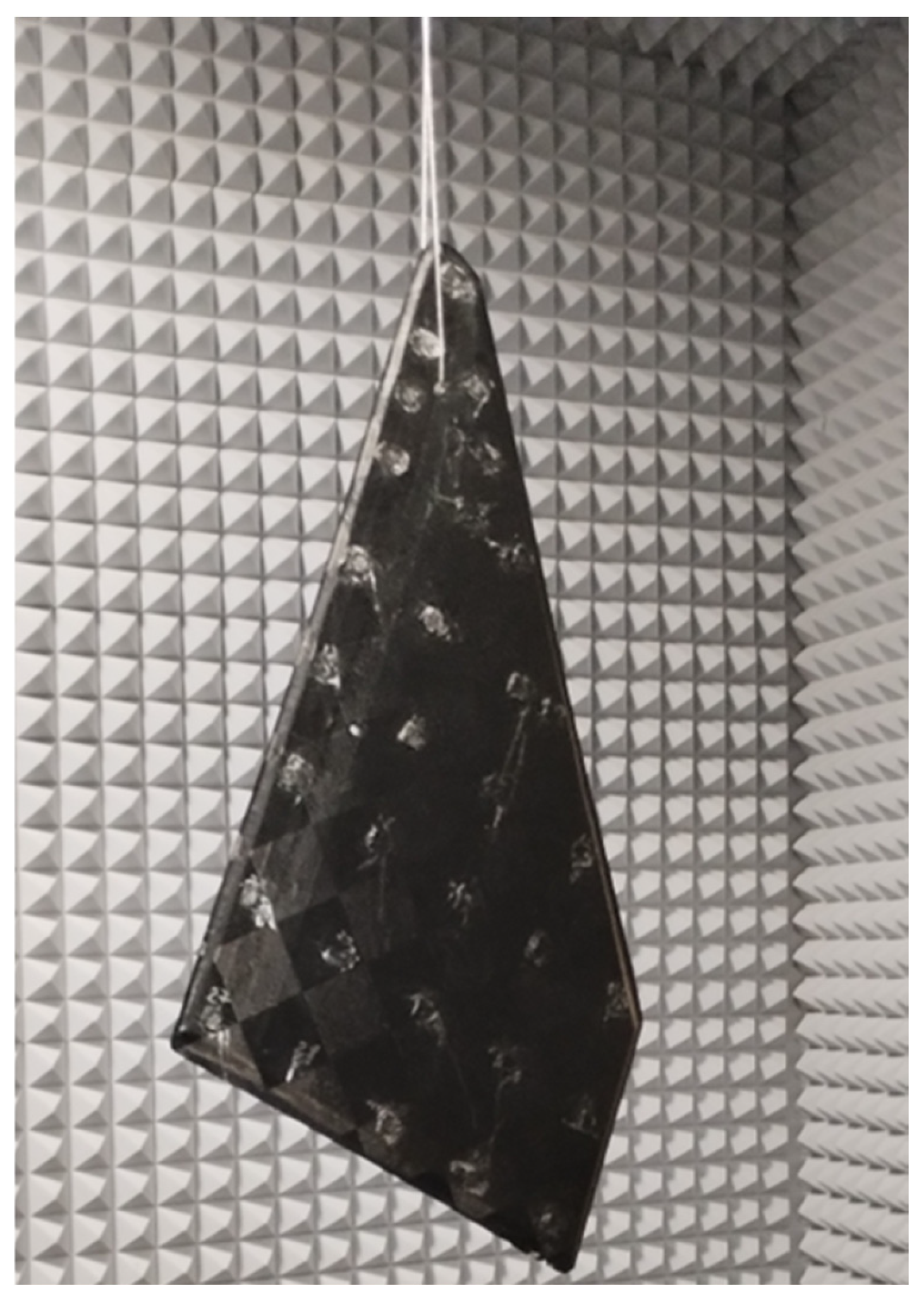
In the first configuration, the winglet was tested under nominal free–free boundary conditions by suspending it using soft elastic cords (Figure 6). The stiffness of the suspension was estimated to be 100 N/m, which, in combination with the mass of the winglet, resulted in suspension frequency of 13.5 Hz. This setup minimizes constraint forces and stiffness contributions from the supports, allowing the intrinsic dynamic behavior of the structure to be captured. Such a configuration is commonly regarded as the reference condition for experimental modal analysis, as it enables direct comparison with numerical models formulated under unconstrained conditions.
Figure 6.
Free–free suspension of the winglet using elastic cords.
2.4. Free–Free Approximation Using Flexible Foam Support
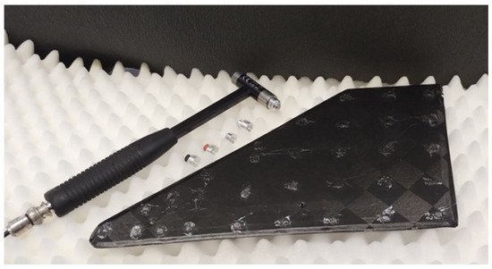
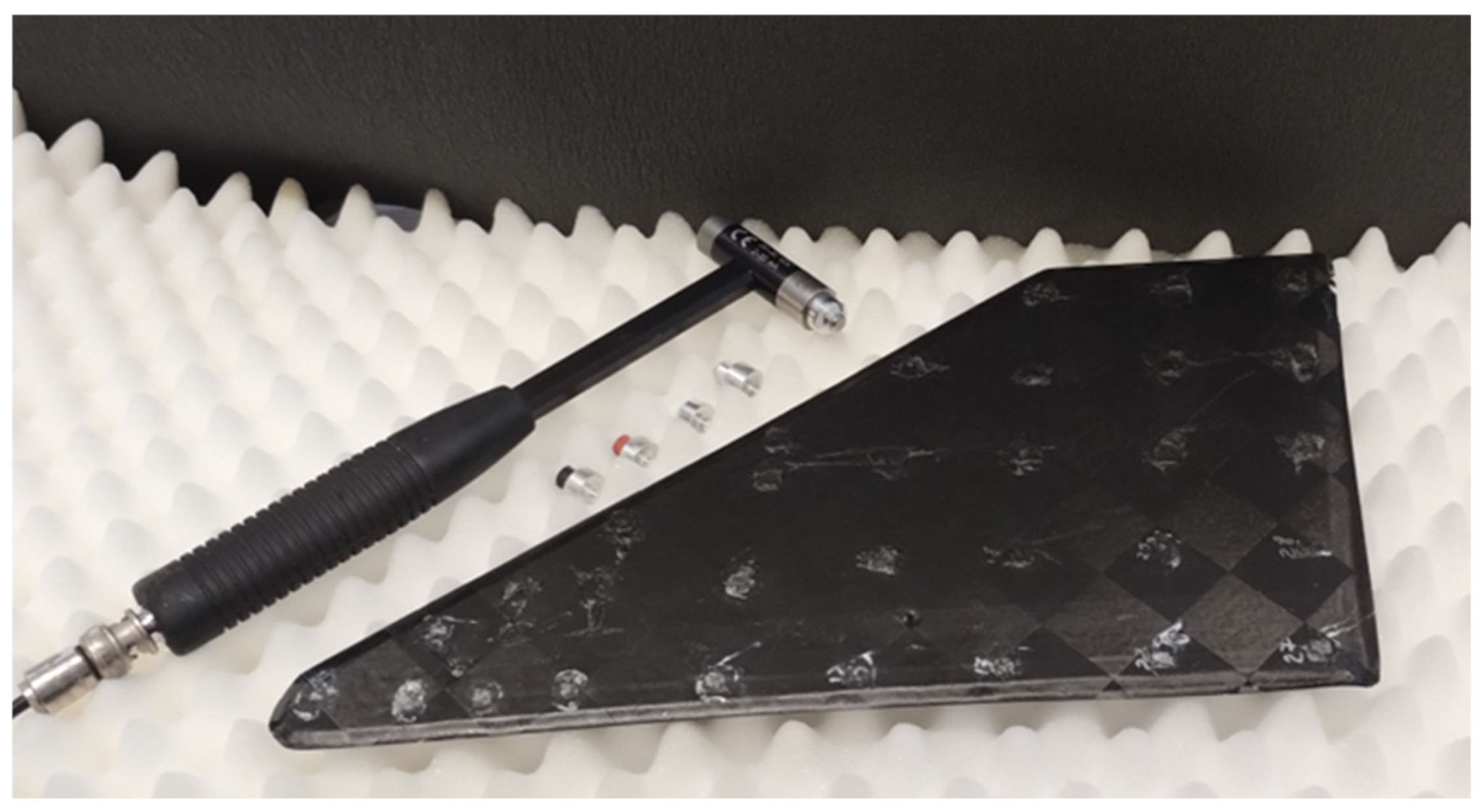
In the second configuration, the winglet was placed on a soft, highly compliant prismatic patterned foam sheet (Figure 7). Prism foam pads are commonly used in modal testing to provide minimal reaction forces, thereby approximating free–free boundary conditions while offering stable and practical testing arrangement. This setup reflects a commonly used alternative in laboratory environments.
Figure 7.
Winglet supported on a soft prismatic foam, with modal hammer with interchangeable impact tips.
2.5. Fixed Boundary Conditions
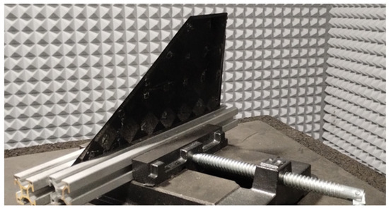
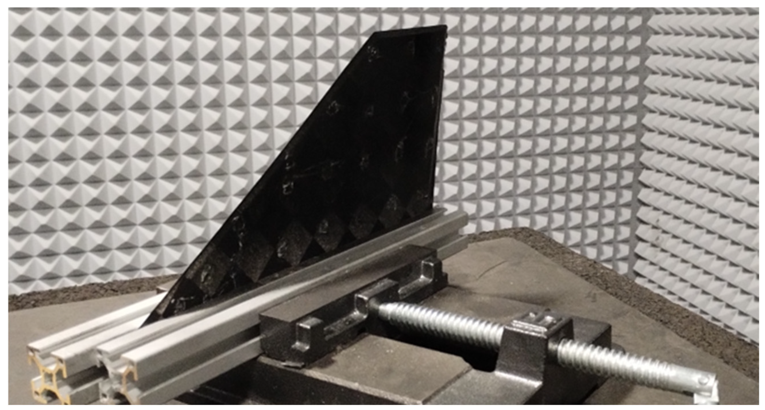
In the third configuration, the winglet was tested under fixed boundary conditions by rigidly clamping it at the mounting interface (Figure 8), reproducing the operational attachment to the wing structure. This configuration represents an approximation of the in-service condition of the component and allows the assessment of how boundary constraints alter the natural frequencies and mode shapes relative to the free–free cases. The comparison between fixed and free–free results provides insight into the role of mounting stiffness and load transfer on the dynamic response of wingtip devices in UAV applications.
Figure 8.
Winglet rigidly clamped.
For all test configurations, frequency response functions (FRFs) were computed from the measured force and acceleration signals. The resulting FRFs were subsequently used for modal parameter identification, including natural frequencies and corresponding mode shapes. The adopted measurement grid and testing procedure were designed to ensure sufficient spatial resolution and data consistency for reliable comparison between experimental configurations as well as with the numerical modal analysis.
2.6. Impact Test—Preliminary Results
The modal impact hammer presented in Figure 7 can be equipped with various interchangeable impact tips: hard stainless steel, medium-hard aluminum, medium-hard polymer, soft elastomer, and super-soft elastomer. Tip material influences the contact duration and thus the usable excitation bandwidth. Hard tips provide short contact time and input a spectrum at higher frequencies, whereas soft rubber tips increase contact time at impact in what can lead to insufficient excitation at higher-order modes.
Preliminary impact tests indicated that the hard aluminum tip provided the best quality of excitation. To obtain broadband excitation of the CFRP plate while minimizing the risk of surface damage, the structure was excited using a modally tuned impact hammer equipped with an aluminum tip, which delivers the broad range input without high impact forces as in the case of stainless-steel tips, which increase local contact stresses and thus the risk of surface damage or delamination [22,23].
The lightweight nature of the CFRP wing structure initially suggested the use of a low-mass miniature impact hammer. However, preliminary impact testing showed that the structure failed to provide a reliable accelerometer response due to insufficient energy transfer. To address this issue, an additional 25 g extender mass was added to the modal hammer to increase the impact amplitude and achieve broad, stable excitation across the frequency range of interest. In all configurations, the winglet was excited using a modal impact hammer (PCB 086C01, PCB Piezotronics, New York, NY, USA), using a roving accelerometer method, where the excitation point was constant during each test set.
For each measurement point, three consecutive hammer impacts were applied, and the corresponding frequency response functions were averaged to improve the repeatability of the identified modal parameters. The structural response was measured using a miniature triaxial piezoelectric accelerometer (PCB 356A03, PCB Piezotronics, New York, NY, USA) [24], sequentially repositioned to predefined measurement locations distributed over the winglet surface (Figure 4). Frequency response functions (FRFs) were computed from the acquired force and acceleration signals and subsequently used for modal parameter identification, including natural frequencies and corresponding mode shapes. The analog channel sampling rate was 10 kHz, and the frequency resolution was set to 0.5 Hz at 10,000 spectral lines with 2 s of data acquisition. A force window was applied to the excitation channel, with a width of 5% of the acquired time data, while no windowing was used for the response channels. All tests were conducted at an ambient temperature of 22 ± 1 °C, relative humidity of 45–50%, and negligible environmental vibration levels. Coherence plots were analyzed during the tests; after each impact (the second and third impacts), if the coherence plot showed values lower than 0.95 at given frequencies or over a broader frequency range, the measurement was rejected. Causes of low coherence were investigated if the low coherence occurred outside the antiresonances.
The use of a 1 gm triaxial miniature accelerometer on lightweight structures introduces added mass and can measurably influence the systems response. A non-contact response measurement method, such as Laser Doppler Vibrometry (LDV), avoids accelerometer-induced mass loading, unfortunately its application to structures tested under free–free boundary conditions presents several methodological challenges. In some cases, the test object is supported on elastic bands (e.g., soft foam or elastic cords) to approximate a free–free-support condition. Relative motion of the test object in regard to the LDV unit can disrupt vibrometer signal stability, especially in the case of CFRP low-reflective and curved surfaces. Although vibrometry is advantageous for eliminating mass-loading effects, careful environmental isolation, optical target preparation, and stabilization of the free–free-support system are essential to ensure measurement integrity.
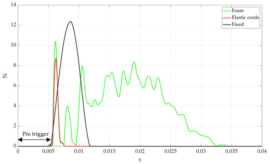
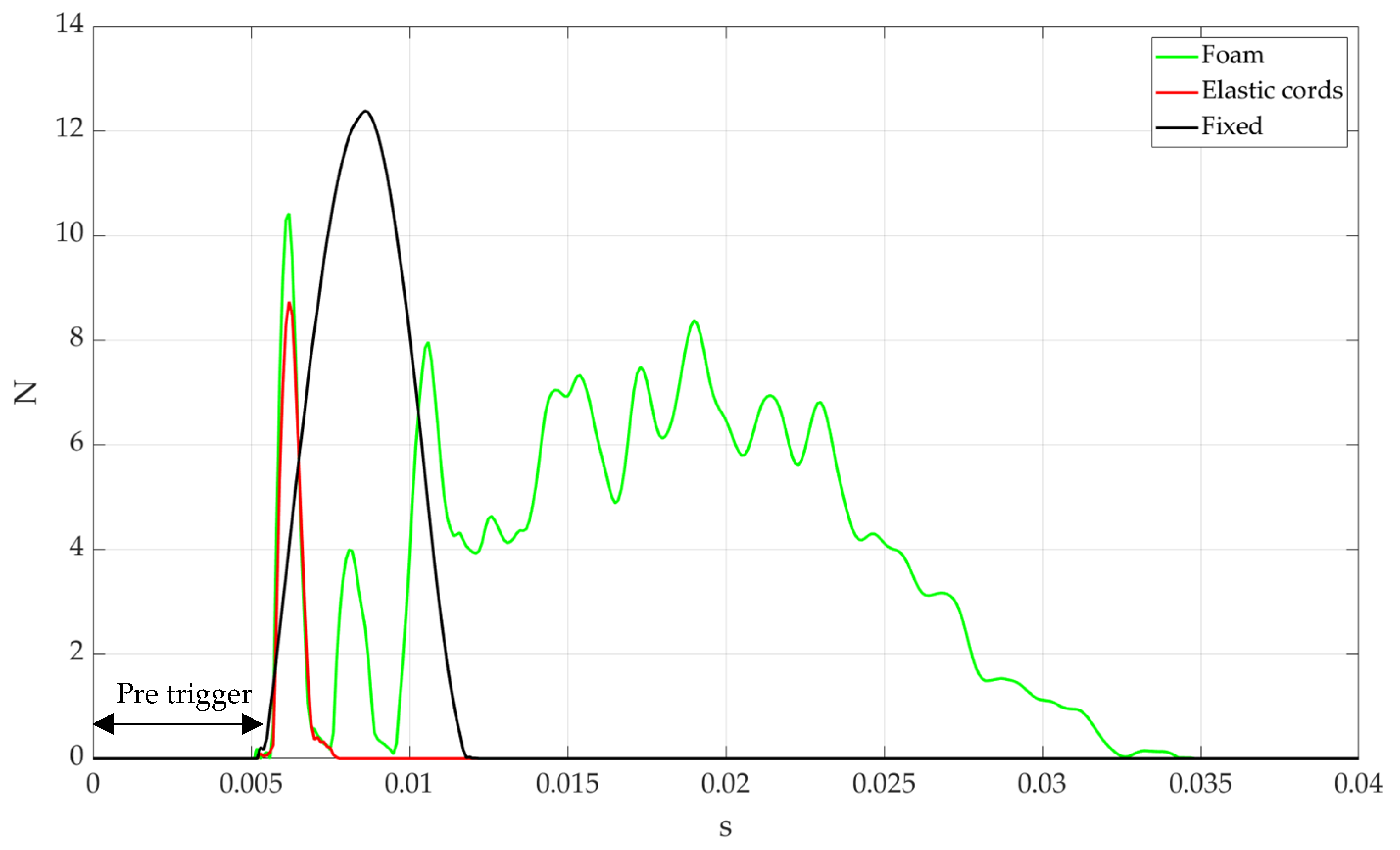
For this preliminary research stage, the 1 gm triaxial accelerometer was selected to measure the structural responses. This choice provides stable and repeatable measurements without the optical alignment challenges and relative displacement of the sample–LDV unit. It is worth noting that the authors explicitly acknowledge and account for the potential influence of the accelerometer on the measured dynamic response. The use of a triaxial sensor allowed the simultaneous acquisition of acceleration components in three orthogonal directions, enabling the identification of both bending- and torsion-dominated vibration modes. Particular attention was paid to maintaining consistent sensor orientation and attachment conditions during the measurements, as the low mass of the structure makes the results sensitive to local mass perturbations. During the initial phase of each test configuration—each support condition of the winglet—the modal hammer force–time signal and power spectrum density were analyzed to verify the quality of the system excitation. Figure 9 presents the excitation forces recorded at the impact–hammer force sensor during excitation achieved at each support condition.
Figure 9.
Measured impact–hammer force signals for the different winglet support conditions.
In the case of the soft foam support, it was impossible to achieve good-quality excitation, as numerous impacts are visible. The prismatic patterned foam used for support created a strong damping support condition that prevented efficient force transmission from the impact hammer. The prism patterning of the foam introduces numerous small contact points with the test object, which increase energy dissipation during impact. As a result, when the hammer strikes the structure, a significant portion of the input energy was absorbed or redirected by the deformable foam instead of being transmitted into the structure. This led to multiple hammer impacts, extended contact durations, and a significant reduction in mid- and high-frequency content. In the case of the fixed support, it was possible to introduce a single-impact excitation, although much effort was needed to prevent double impacts in free-hand operation. The excitation impulse is also wider than in the case of the free–free condition achieved by means of elastic cords.
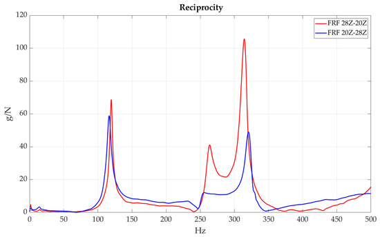
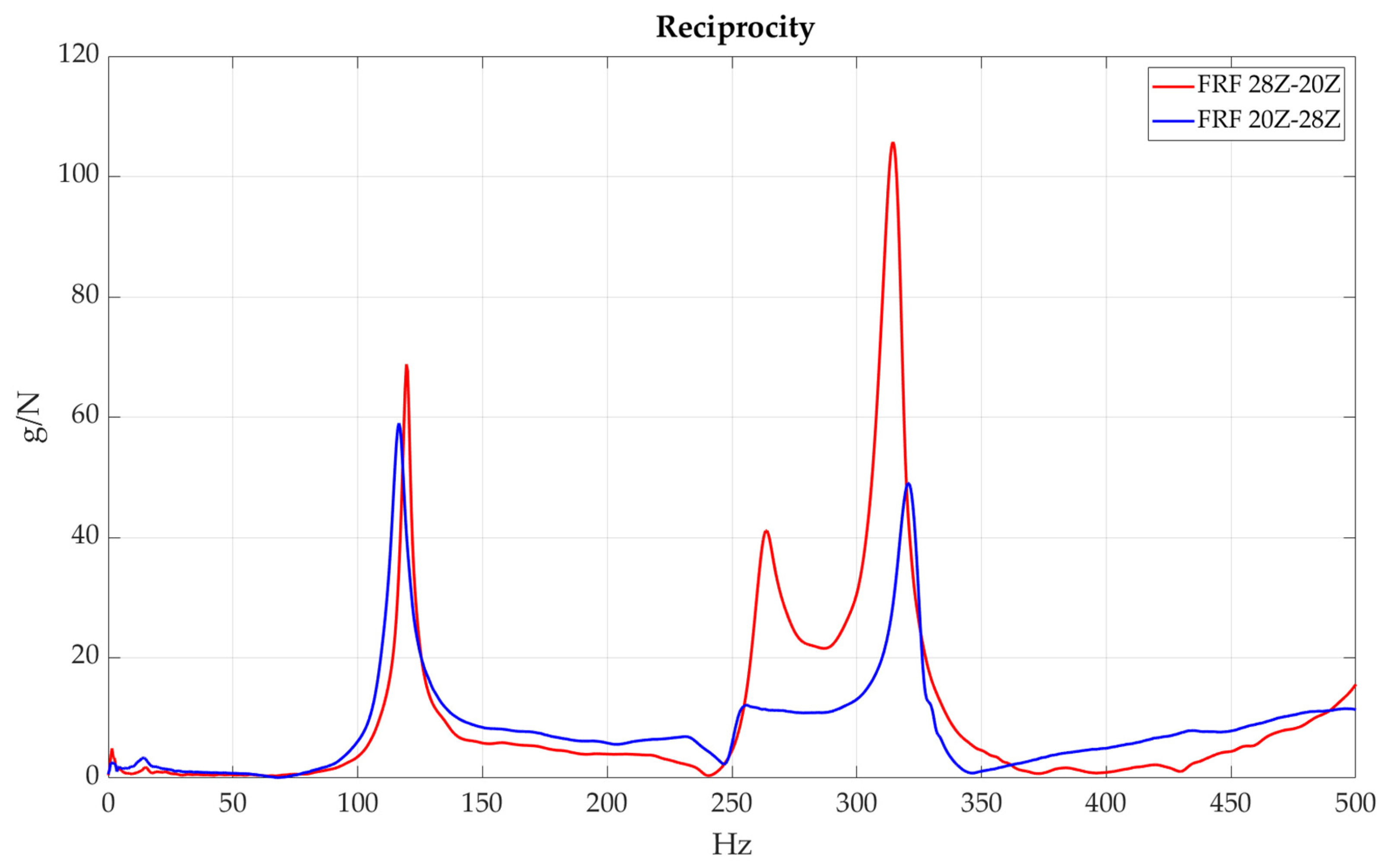
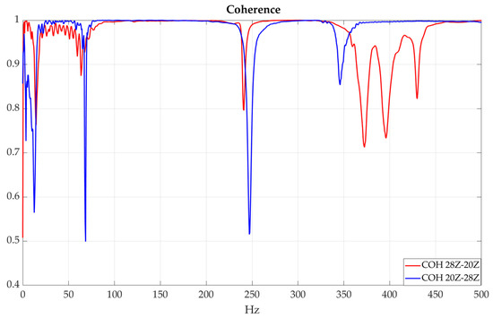
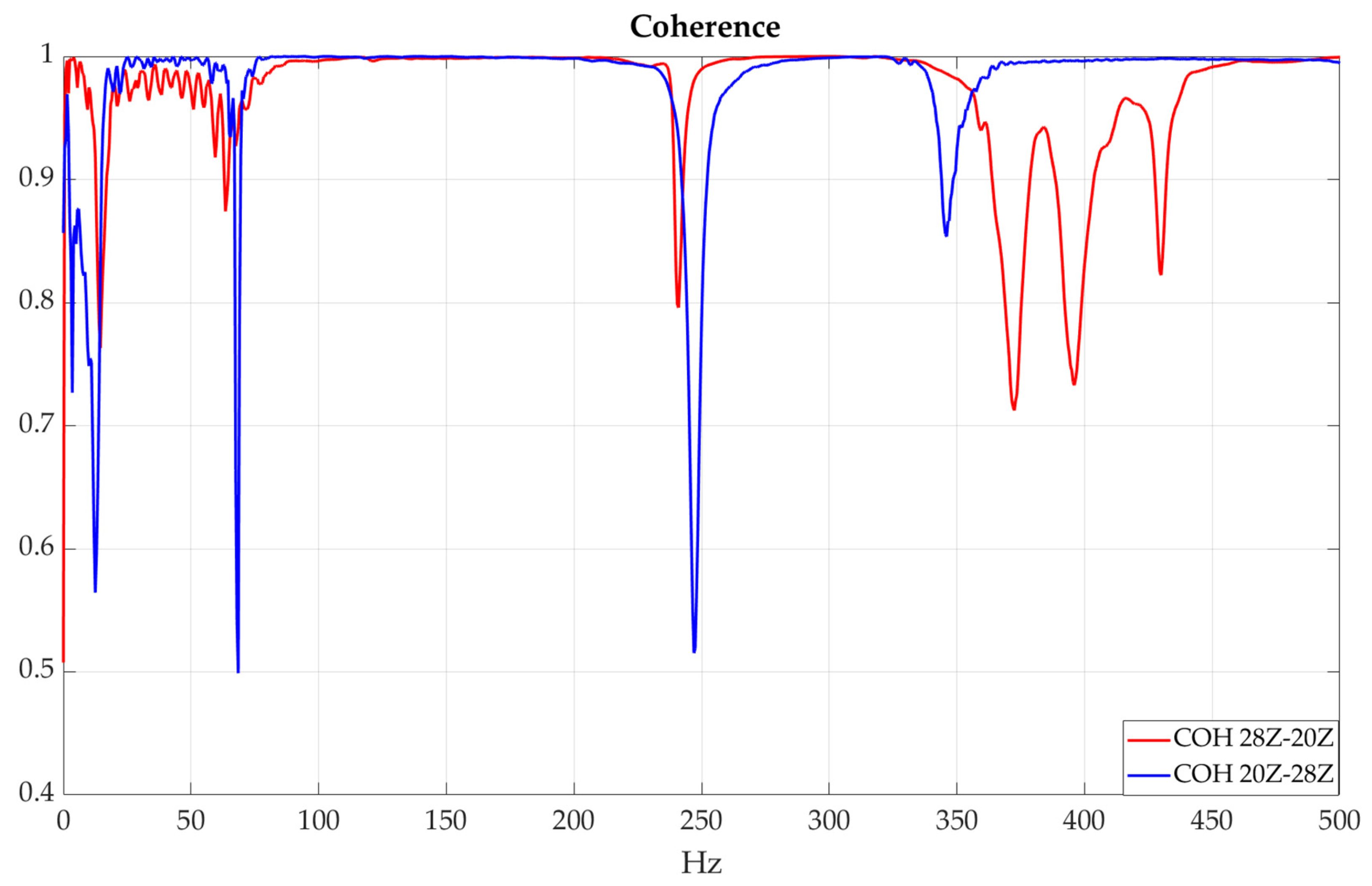
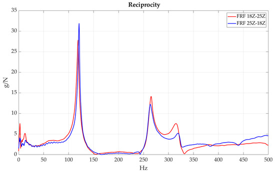
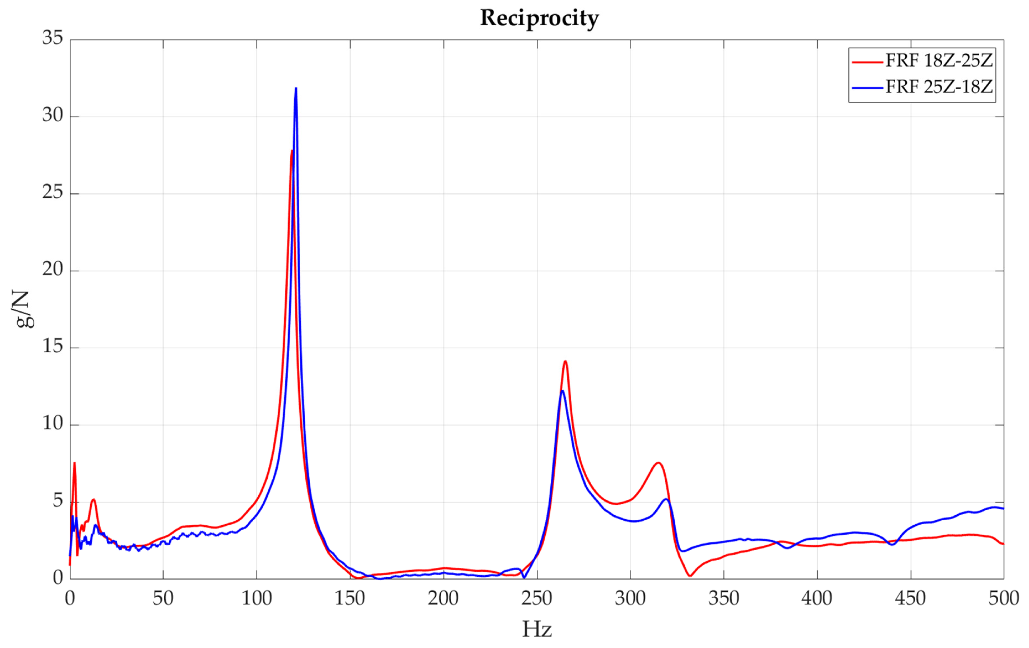
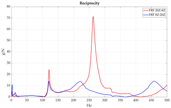
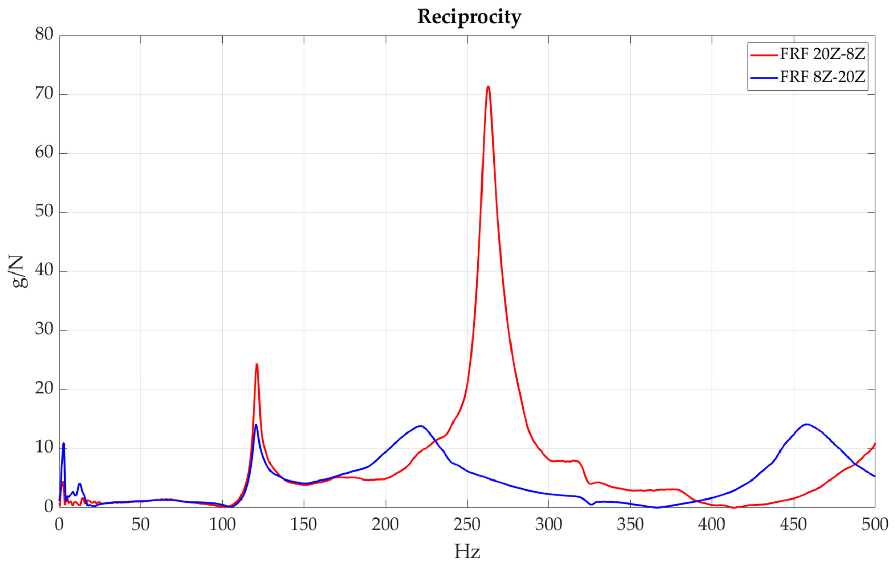
Reciprocity analysis was used to verify the linearity and stability of the test setup in the free–free-support condition. FRFs obtained for point A (driving point) to point B (response) were compared to the FRFs obtained in the reverse direction, point B (driving point) to point A (response). Three pairs of points (28–20, 18–25, 20–8) were analyzed for the free–free elastic band support condition. In all analyzed cases (firstly on Figure 10), the reciprocity test reveals differences in FRF amplitude and frequency. Additionally, coherence reciprocity between points 28 and 20 was evaluated and is presented in Figure 11. All analyses case as well presented in Figure 12 and Figure 13.
Figure 10.
FRF reciprocity comparison—Points 28 and 20, Z axis.
Figure 11.
Coherence reciprocity comparison—Points 28 and 20, Z axis.
Figure 12.
FRF reciprocity comparison—Points 18 and 25, Z axis.
Figure 13.
FRF reciprocity comparison—Points 8 and 20, Z axis.
It can be stated that the main reason for the identified non-reciprocity is the mass loading caused by the roving accelerometer. Although the main acceleration peaks are still visible in the spectrum, frequency shifts are visible. The modal mass at resonances, which is the effective mass associated with a vibration mode at the measurement point, is comparable with the accelerometer mass, causing visible mass loading. Another point to consider in the case of non-reciprocity are double hammer impacts, unstable boundary conditions, structural nonlinearities, and delamination. The first two causes can be deemed irrelevant—double-hit warning conditions were set for the measuring system and each hammer hit was thoroughly investigated for double impact. The support condition was not modified throughout the test procedure. Structural nonlinearities due to matrix micro-cracking or delaminations cannot be outruled nor confirmed, as mass loading due to the roving accelerometer is surely present in the system.
Despite the visible non-reciprocity and test setup limitations, the experimental testing was conducted due to the preliminary nature of the research, where the main objective is to assess the usefulness of the test setup, excitation method, and data acquisition. Further structural testing was conducted to explore limitations and challenges in structural testing of lightweight composite structures. At this point, it is already clear that future work should incorporate reduced mass loading, refined support conditions, and further analysis of structural nonlinearities due to the anisotropic nature of CFRP.
3. Results
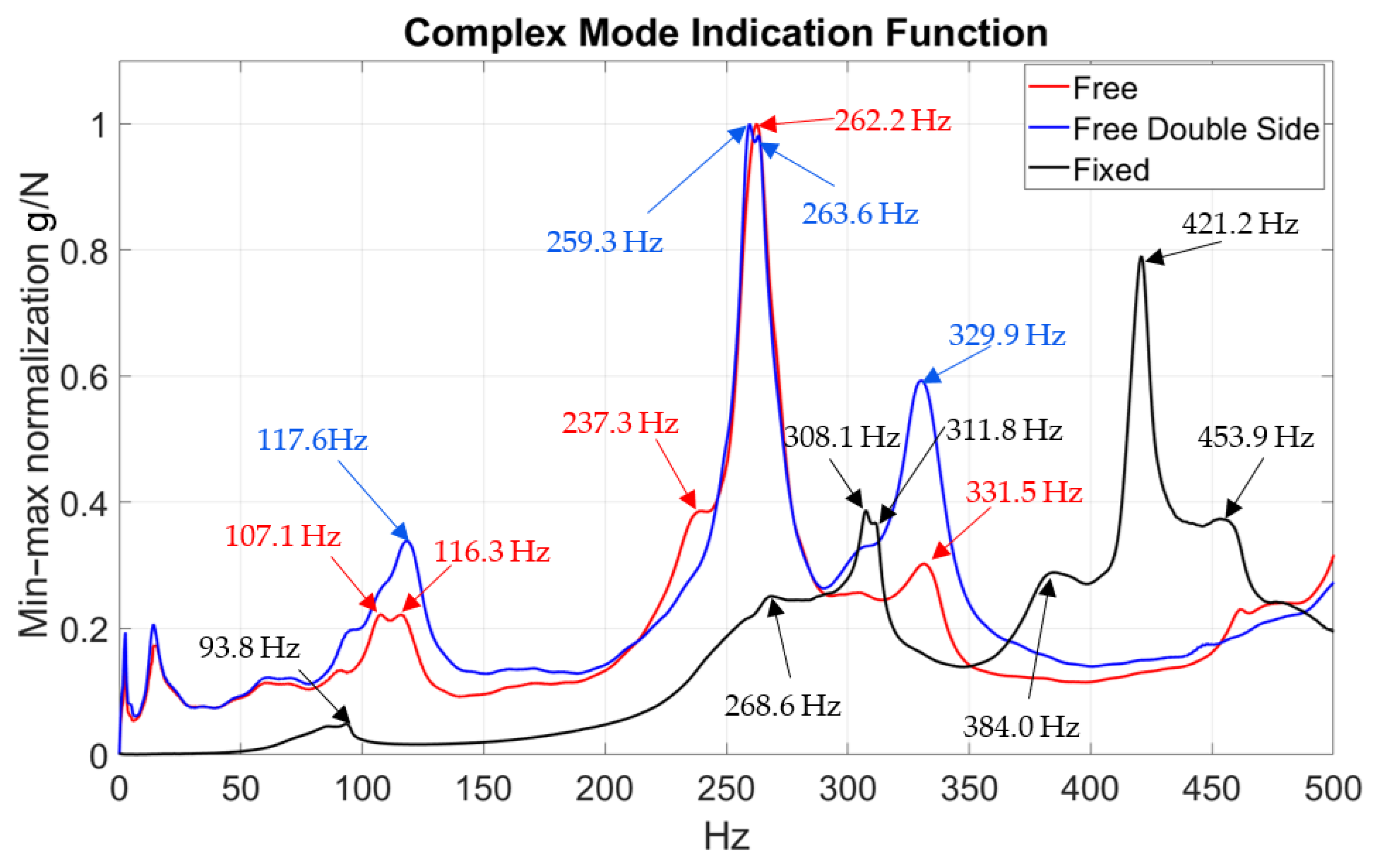
Singular value decomposition of the FRF matrix was implemented to compute the complex mode indicator function (CMIF) for each test setup. At each instance, the number of FRFs is different due to the number of response points. Dominant singular values at modal frequencies become numerically larger as the number of response points, and thus the number of FRFs, increases. In order to compare the CMIF functions calculated for each test condition, a max–min normalization was conducted to improve the visual representation of the data. This normalization ensures that the comparison emphasizes changes in modal frequency content rather than amplitude differences caused by different numbers of FRFs used in the CMIF computation. Each CMIF was normalized with a standard min–max scaling where the min(x) and max(x) are the minimum and maximum CMIF values for each respective support condition (free–free, foam supported, and fixed). This procedure scales each CMIF curve to the range 0–1, enabling all boundary condition results to be shown in a single figure without introducing misleading amplitude differences.
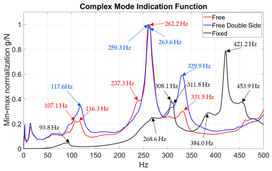
As visible in Figure 14, in the case of the free–free condition, the CMIF function peaks around 260 Hz for both free test conditions. The introduction of additional response points at the CFRP—measurements conducted on both sides of the winglet—did influence the shape of the CMIF function. At the dominant peak, it splits into two sub-peaks in the case of the double-sided test setup. Further investigation of the mode shapes occurring at the two sub-peaks reveals a similar mode shape (Figure 15), and the Modal Assurance Criterion of those two modes equals 0.57, which indicates one mode obtained under altered measurement conditions, such as mass loading and changes in local bending curvature.
Figure 14.
Complex mode indicator function at various support conditions.
Figure 15.
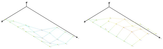
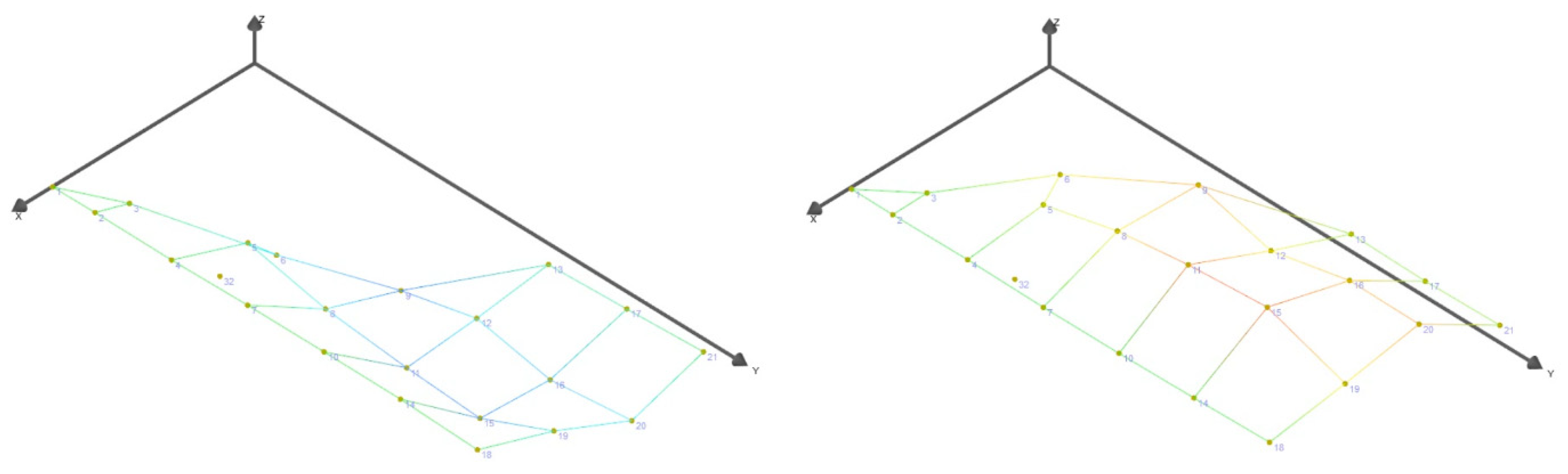
Mode shapes at two sub-peaks: 259.3 Hz and 263.6 Hz.
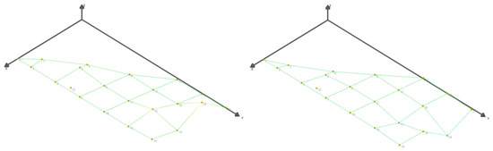
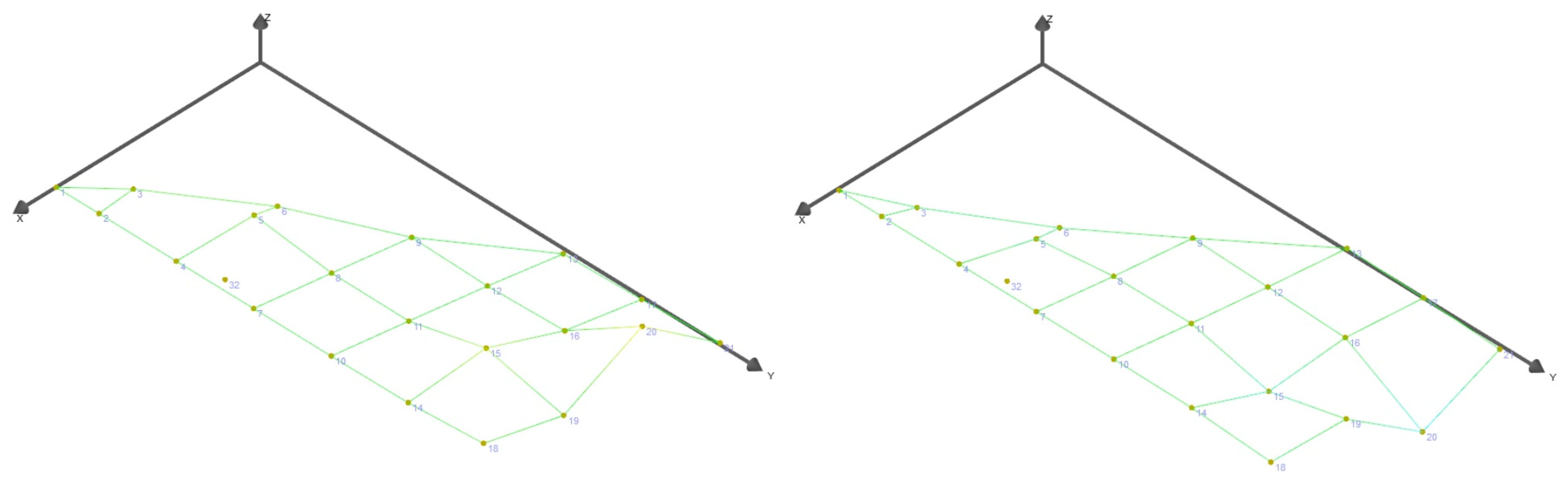
The main displacement occurs alongside the longer side of the winglet, while no visible vibration occurs at other points of the object. The remaining regions behave quasi-rigidly due to higher local stiffness and geometric constraint. The first two modes visible below 50 Hz in the case of both free conditions represent rigid-body motion caused by the stiffness of the elastic cords and their length. In the case of the single-sided free-support condition, two modes are consequently present at 107.1 Hz and 116.3 Hz. At first glance, both identified mode shapes are similar (Figure 16), but detailed analysis of the mode-shape animation shows a more complex shape occurring at 116.3 Hz, where displacement is visible not only at the tip of the winglet but also at the opposite edge. This is a bending mode. The MAC value for those two modes is equal to 0.19, also indicating two separate modes.
Figure 16.
Mode shapes at 107.1 Hz and 116.3 Hz.
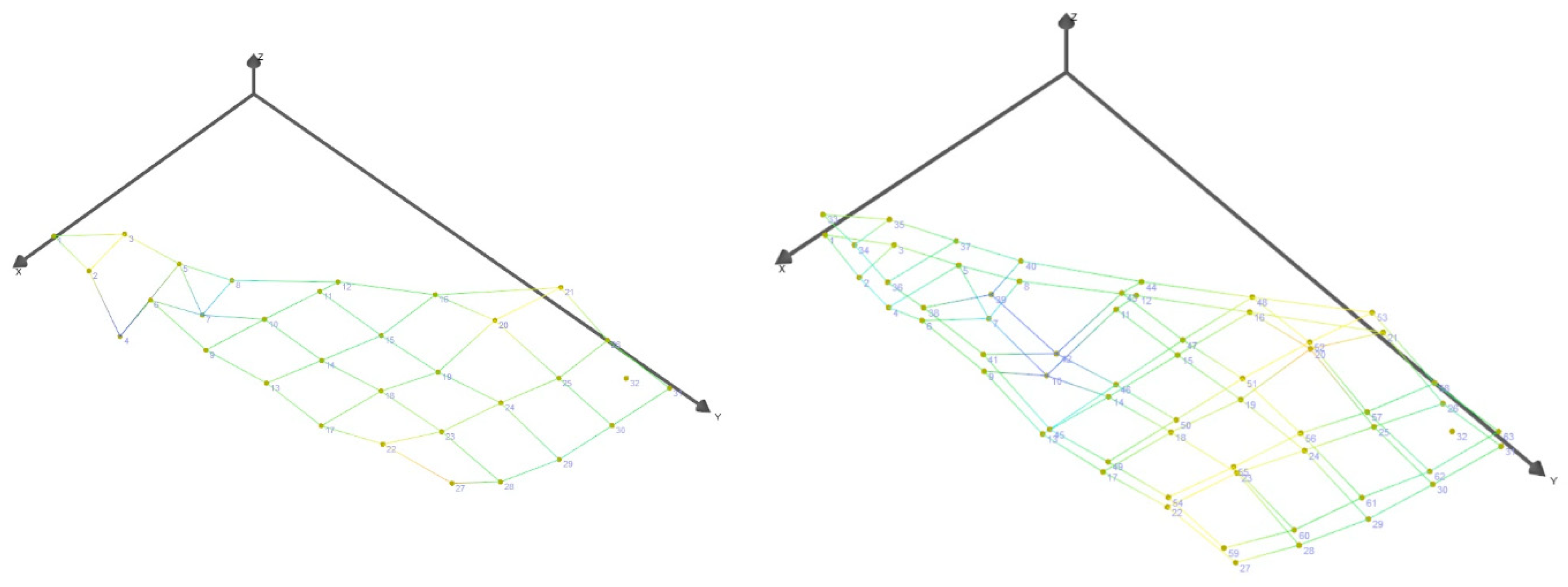
Additional FRFs included in the CMIF computation for the double-sided response caused changes in this frequency range and a more pronounced peak is visible at 117.6 Hz, making it the dominant frequency in this region. The mode occurring at 116.3 Hz for the single-sided measurement was shifted upward to 117.6 Hz, as a detailed analysis of the mode-shape animations indicates the same shape (Figure 17). The central region of the structure contributes most significantly to the dynamic response, acting as the primary deformation zone while the remaining areas remain relatively stiff. The CMIF value at 117.6 Hz is also higher due to the increased number of FRFs used in the computation.
Figure 17.
Mode shapes at 116.3 Hz, single-sided response, and 117.6 Hz, double-sided response.
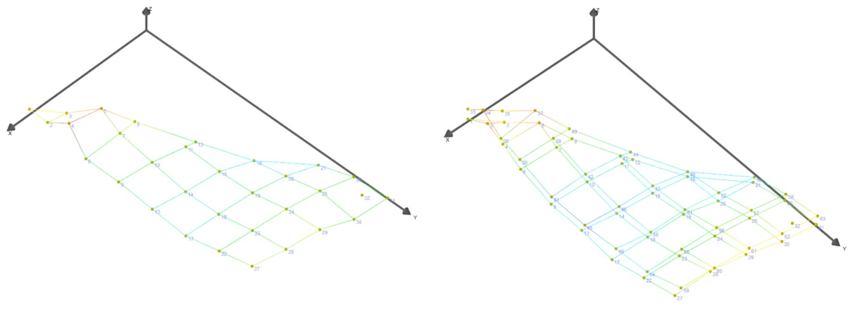
Further comparison of the CMIF peaks indicates modes at 331.5 Hz for the single-sided measurement and 329.9 Hz for the double-sided response (Figure 18). In this case, a frequency shift is also visible, as the mode-shape animation presents similar patterns. Once again, the CMIF values are greater for the double-sided responses, which is to be expected.
Figure 18.
Mode shapes at 331.5 Hz, single-sided response, and 329.9 Hz, double-sided response.
A significant difference in the CMIF is visible in the case of the fixed-support condition. As presented in Figure 8, the longer edge of the winglet was clamped in a vise, significantly reducing the area of the winglet that can respond to impacts. The first modes identified in the free condition were concentrated around the winglet tip. Since the tip of the winglet is fixed in the vise, the first mode differs substantially in both frequency and shape. Figure 19 presents the first mode shape identified for the fixed condition at 93.8 Hz, which consists of bending of the winglet around the Y-axis.
Figure 19.
Mode shapes at 93.8 Hz—a single mode at two end positions.
The dominant peak of the fixed-support CMIF function is shifted to higher frequencies compared with both free-support conditions. The main peak was identified at 421.2 Hz, and the corresponding mode shape is shown in Figure 20. This mode shape can be compared in form and complexity to the modes at 331.5 Hz for the single-sided response and 329.9 Hz for the double-sided response, presented in Figure 18. Naturally, due to the clamping of the winglet, the portion of the structure able to respond to excitation is smaller than in the free–free condition. The resulting change in effective geometry, and the associated increase in stiffness, shifts the mode frequency to higher values.
Figure 20.
Mode shapes at 421.2 Hz—a single mode at two end positions.
4. Conclusions
The experimental results demonstrate that boundary conditions critically influence the dynamic characteristics of the composite winglet. Transitioning from free–free to rigidly fixed conditions shifted the dominant modal frequency from 260 Hz to 420 Hz, reflecting the increased stiffness and reduced effective vibrating mass due to clamping (Figure 20). Modes dominated by the winglet tip under free–free conditions were strongly affected, with modal peak splitting observed at higher frequencies.
The free–free approximation using prismatic foam support proved unsuitable, introducing excessive damping that dissipated input energy and led to unreliable modal identification. Double-sided response measurements revealed richer modal information and measurable frequency shifts, but were sensitive to measurement alignment and sensor mass. For frequencies below 500 Hz, single-sided measurements provided reliable global modal data, offering a faster and simpler approach for lightweight sandwich composites.
Excitation quality was found to be a critical factor. Impact hammer selection directly affected the modal response: soft tips produced prolonged contact times and insufficient high-frequency content, whereas overly hard tips risked local surface damage. The aluminum tip provided the best compromise, exciting both low- and higher-order modes. Moreover, the low mass of the structure made it necessary to add an extender mass to the hammer, stabilizing force amplitude and improving repeatability of the measured FRFs. These results indicate that for ultra-lightweight structures, hammer tip material, tip hardness, and added mass are essential parameters to achieve broadband excitation without damaging the structure.
Sensor mass also affected high-frequency responses, confirming that conventional assumptions of negligible accelerometer influence do not hold for ultra-lightweight UAV components. The foam core contributes to stiffness and damping, affecting modal clarity and excitation efficiency.
Future work should employ non-contact techniques such as Laser Doppler Vibrometry, and extend tests to wing-mounted configurations to capture realistic aeroelastic interactions. High-fidelity FE models, incorporating layered composite behavior and realistic boundary stiffness, should be correlated with experiments.
These findings provide quantitative guidance for experimental modal testing of ultra-lightweight UAV structures, informing boundary condition selection, measurement strategy, and excitation setup, with direct implications for aeroelastic and flutter assessments.
Author Contributions
Conceptualization, J.W., A.K., M.S. and O.P.; methodology, J.W., K.J., M.K. and M.M.; software, J.W., K.J., M.M. and O.P.; validation, J.W., A.K., M.S., O.P. and M.K.; formal analysis, M.S. and M.K.; investigation, J.W., K.J. and M.M.; resources, O.P. and A.K.; data curation, J.W., K.J., M.S. and O.P.; writing—original draft preparation, J.W., K.J. and M.M.; writing—review and editing, A.K., M.S., O.P. and M.K.; visualization, J.W. and M.M.; supervision, A.K., M.S., O.P. and M.K.; project administration, A.K. and O.P. All authors have read and agreed to the published version of the manuscript.
Funding
This research received no external funding.
Data Availability Statement
All data included in this research are available upon request from the corresponding author.
Conflicts of Interest
The authors declare no conflicts of interest.
References
- Deng, H.; Huang, J.; Liu, Q.; Zhao, T.; Zhou, C.; Gao, J.; Deng, H.; Huang, J.; Liu, Q.; Zhao, T.; et al. A Distributed Collaborative Allocation Method of Reconnaissance and Strike Tasks for Heterogeneous UAVs. Drones 2023, 7, 138. [Google Scholar] [CrossRef] [Scilit]
- Gargalakos, M. The Role of Unmanned Aerial Vehicles in Military Communications: Application Scenarios, Current Trends, and Beyond. J. Def. Model. Simul. Appl. Methodol. Technol. 2021, 21, 154851292110316. [Google Scholar] [CrossRef] [Scilit]
- Colomina, I.; Molina, P. Unmanned Aerial Systems for Photogrammetry and Remote Sensing: A Review. ISPRS J. Photogramm. Remote Sens. 2014, 92, 79–97. [Google Scholar] [CrossRef] [Scilit]
- Saponi, M.; Borboni, A.; Adamini, R.; Faglia, R.; Amici, C.; Saponi, M.; Borboni, A.; Adamini, R.; Faglia, R.; Amici, C. Embedded Payload Solutions in UAVs for Medium and Small Package Delivery. Machines 2022, 10, 737. [Google Scholar] [CrossRef] [Scilit]
- Kierzkowski, A.; Kisiel, T.; Milewski, M.; Török, Á.; Stosiak, M.; Wróbel, J. Computer-Aided Simulation of Unmanned Aerial Vehicle Composite Structure Dynamics. Transport 2024, 39, 302–312. [Google Scholar] [CrossRef] [Scilit]
- Elham, A.; van Tooren, M.J.L. Winglet Multi-Objective Shape Optimization. Aerosp. Sci. Technol. 2014, 37, 93–109. [Google Scholar] [CrossRef] [Scilit]
- Kumpati, R.; Skarka, W.; Skarka, M.; Brojan, M.; Kumpati, R.; Skarka, W.; Skarka, M.; Brojan, M. Enhanced Optimization of Composite Laminates: Multi-Objective Genetic Algorithms with Improved Ply-Stacking Sequences. Materials 2024, 17, 887. [Google Scholar] [CrossRef] [Scilit]
- Nikolaou, E.; Karatzas, E.; Kilimtzidis, S.; Kostopoulos, V.; Nikolaou, E.; Karatzas, E.; Kilimtzidis, S.; Kostopoulos, V. Winglet Design for Class I Mini UAV—Aerodynamic and Performance Optimization. Eng. Proc. 2025, 90, 111. [Google Scholar] [CrossRef] [Scilit]
- González, P.; Chaves Barbosa, G.; García Quesada, Á.; Stavorinus, G.; Silvestre, F.; Hilger, J.; Hanke, C.; Voß, A.; Krüger, W. Wind Tunnel Testing and Modal Validation of Tu-Flex’s High Aspect-Ratio Wings. In Proceedings of the International Forum on Aeroelasticity and Structural Dynamics IFASD-2024, The Hague, The Netherlands, 17–21 June 2024. [Google Scholar]
- Maharudra; Arya, B.; Rajanna, T. Effect of Ply-Orientation and Boundary Conditions on the Vibrational Characteristics of Laminated Composite Panels Using HODST. Mater. Today Proc. 2020, 20, 134–139. [Google Scholar] [CrossRef] [Scilit]
- Guo, Z.; Sheng, M.; Zhang, K. Effect of Boundary Conditions on Vibration Characteristics of a Sandwich Plate with Viscoelastic Periodic Cores. Machines 2025, 13, 863. [Google Scholar] [CrossRef] [Scilit]
- Erkliğ, A.; Bulut, M.; Yeter, E. The Effect of Hybridization and Boundary Conditions on Damping and Free Vibration of Composite Plates. Sci. Eng. Compos. Mater. 2015, 22, 565–571. [Google Scholar] [CrossRef] [Scilit]
- Qu, C.; Yan, Q.; Zou, X.; Gou, D.; Liu, X. Experimental Study on Modal Testing Methods for Typical Composite Honeycomb Sandwich Structures. Int. J. Front. Eng. Technol. 2024, 6, 13–24. [Google Scholar] [CrossRef] [Scilit]
- Karpenko, M.; Stosiak, M.; Deptuła, A.; Urbanowicz, K.; Nugaras, J.; Królczyk, G.; Żak, K. Performance Evaluation of Extruded Polystyrene Foam for Aerospace Engineering Applications Using Frequency Analyses. Int. J. Adv. Manuf. Technol. 2023, 126, 5515–5526. [Google Scholar] [CrossRef] [Scilit]
- Zhang, L.; Liao, W.; Liu, B.; Feng, S.; Fan, J. Thermal Model Test and Multi-Scale Simulation Method for the Lattice-Structured Air Rudder of Hypersonic Flight Vehicle. Aerosp. Sci. Technol. 2026, 174, 111885. [Google Scholar] [CrossRef] [Scilit]
- Qaumi, T.; Hashemi, S.M. Experimental and Numerical Modal Analysis of a Composite Rocket Structure. Aerospace 2023, 10, 867. [Google Scholar] [CrossRef] [Scilit]
- Chung, S.; Kim, C.-J. Evaluation of the Modal Parameters of a Unidirectional Carbon-Based Composite Structure Using the Influential Factor of Static Loading. Materials 2024, 17, 3209. [Google Scholar] [CrossRef] [Scilit]
- Pavlović, A.; Sintoni, D.; Minak, G.; Fragassa, C. On the Modal Behaviour of Ultralight Composite Sandwich Automotive Panels. Compos. Struct. 2020, 248, 112523. [Google Scholar] [CrossRef] [Scilit]
- 2024 Collegiate Design Series SAE Aero Design Rules. Available online: https://www.saeaerodesign.com/cdsweb/gen/DownloadDocument.aspx?DocumentID=f9dcb79b-b8d4-42b2-a1d3-2af1fb16aee7 (accessed on 9 April 2026).
- Gupta, S.; Kumar, S.; Kumar, R. Control of Leading-Edge Vortices over Delta Wing Using Flow Control Methods: A Review. Mater. Today: Proc. 2022, 50, 2189–2193. [Google Scholar] [CrossRef] [Scilit]
- Milewski, M.; Kierzkowski, A.; Kucharski, M.; Zielonka, P. Inverse Method for Material Characterization of a UAV Composite Wing Based on FEM and Dynamic Response. Eksploat. I Niezawodn.–Maint. Reliab. 2025, 28. [Google Scholar] [CrossRef] [Scilit]
- Huo, L.; Alderliesten, R.; Sadighi, M. Delamination Initiation in Fully Clamped Rectangular CFRP Laminates Subjected to Out-of-Plane Quasi-Static Indentation Loading. Compos. Struct. 2023, 303, 116316. [Google Scholar] [CrossRef] [Scilit]
- Brooks, R.A.; Liu, J.; Hall, Z.E.C.; Joesbury, A.M.; Harper, L.T.; Liu, H.; Kinloch, A.J.; Dear, J.P. The Relationship Between the Extent of Indentation and Impact Damage in Carbon-Fibre Reinforced-Plastic Composites after a Low-Velocity Impact. Appl. Compos. Mater. 2024, 31, 1869–1888. [Google Scholar] [CrossRef] [Scilit]
- Miniature Triaxial ICP Accelerometer Data Sheet. Available online: https://www.pcb.com/Resources/Product-Literature/MiniatureTriaxialICPAccelerometer (accessed on 9 April 2026).

Disclaimer/Publisher’s Note: The statements, opinions and data contained in all publications are solely those of the individual author(s) and contributor(s) and not of MDPI and/or the editor(s). MDPI and/or the editor(s) disclaim responsibility for any injury to people or property resulting from any ideas, methods, instructions or products referred to in the content. |
© 2026 by the authors. Licensee MDPI, Basel, Switzerland. This article is an open access article distributed under the terms and conditions of the Creative Commons Attribution (CC BY) license.