


Abstract
Parallel robots are recognized as a promising solution for heavy-load and high-efficiency tasks in modern manufacturing systems. The terminal rigidity is a critical performance metric for parallel robots, significantly affecting their payload capacity and machining accuracy. However, enhancing terminal rigidity is still a challenge due to the inherent design conflict between high rigidity and lightweight structures. Aiming at this challenge, this study proposes a practical yet high-ly efficient methodology to enhance terminal rigidity without incurring a weight increase. Firstly, an intensity factor is constructed as a discriminant metric to enable a sensitivity-based classification of components. Subsequently, a rigidity enhancement methodology is developed, which entails executing a step-by-step procedure to improve the stiffness of parallel robots. Next, the methodology is applied to a novel redundantly actuated parallel machining robot to demonstrate its practical utility in engineering design. The result shows that the proposed methodology achieves a 31.3% enhancement in linear terminal rigidity, coupled with a 5.6% decrease in overall weight. Finally, experimental verification is conducted through stiffness tests on a laboratory prototype, demonstrating that the enhanced terminal rigidity meets design expectations.
1. Introduction
The rapid growth of the modern manufacturing industry promotes the development of robotic manipulators towards higher flexibility, higher efficiency, and higher load capacity for implementing heavy-load and high-efficiency tasks [1,2,3,4,5]. Due to the inherent shortcomings of large inertia, low payload capacity, and error accumulation, serial robots struggle to meet these development demands in heavy-load and high-accuracy manufacturing tasks. As an alternative solution, parallel robots were proposed as “plug and play” functional modules for constructing heavy-load robotic manipulators. This is attributed to their advantages of a higher rigidity-to-weight ratio, superior dynamic property and inherently higher precision potential (without error accumulation) compared with serial robots [6,7,8,9,10]. This can be exemplified by the commercial applications of Eco-speed [11,12], Tricept [13,14] and Exechon [15,16] in aeronautics and automotive industries, which demonstrate outstanding flexibility and efficiency in machining large-scale structural components with complex surfaces.
High rigidity is an essential performance requirement for parallel robots engaged in heavy-load yet high-efficiency machining tasks. This is because terminal rigidity directly determines payload capability and anti-deformability of parallel robots, thereby influencing their working efficiency and accuracy. From this perspective, it is important to construct a feasible yet effective methodology to enhance the terminal rigidity of parallel robots in the early design stage. A thorough understanding of the stiffness properties of the robotic system is an indispensable prerequisite. This entails addressing two critical issues: (1) how to characterize the component compliance and the terminal rigidity; (2) how to reveal the effect of component compliance on terminal rigidity.
To address the primary issue of terminal rigidity characterization, an efficient stiffness model and a physically intuitive index framework should be constructed. The former is to reveal the transmission relationship from component rigidity to terminal rigidity, thereby yielding a stiffness matrix. The latter is to quantitatively measure the terminal rigidity of parallel robots.
In the aspect of stiffness modeling, the semi-analytical method and the numerical method are two primary ways. The numerical method is characterized by high accuracy but high computational cost. In contrast, the semi-analytical method is computationally efficient but relatively less accurate, owing to the necessary assumptions and simplifications in its formulation. This implies that the semi-analytical method may be more suitable for iterative design and structure optimization, where computational efficiency is critical. The semi-analytical method can be broadly classified into three categories. The first category formulates the relationship between payload and deformation using the principle of virtual work and static equilibrium equations. In like fashion, Liu et al. [17] proposed a unified approach to derive the stiffness matrix of parallel robots. Similar approaches have been employed in recent studies [18,19,20]. The second category uses the substructure synthesis technique to assemble the stiffness matrices of individual components and to derive the overall terminal stiffness matrix. This category has been successfully adopted to establish various stiffness models for many typical parallel robots [21,22,23]. The third category introduces the strain energy method to formulate the relationship between component compliance and terminal rigidity [24]. This approach has proven particularly effective in stiffness modeling of over-constrained parallel robots [25,26,27].
By tracing the existing studies, the formulation of stiffness indices can be broadly classified into two ways. The first way uses the algebraic characteristics of the stiffness/compliance matrix, such as the inverse of the diagonal elements [17,18,19,20,28], the determinant [29], the condition number [30], or the minimum/maximum eigenvalues [31]. However, such indices often suffer from inconsistent physical units and unclear physical meaning arising from a couple of linear and angular stiffness terms. Alternatively, an equidimensional stiffness index grounded in the virtual work principle was proposed. This stiffness index is formulated as the inverse of virtual work done by a unit force, which provides a direct measure of terminal rigidity along a specific axis. Its effectiveness has been demonstrated in recent evaluations of some over-constrained parallel robots [18,24,25,27].
To address the second issue of quantitative relationship, a number of investigations have been conducted to analyze the influence of design parameters on the terminal rigidity of parallel robots. For example, Sun et al. [26] established the mathematical relationship between stiffness indices and structural parameters for a T5 parallel robot. Li et al. [28] revealed the relationship between structural parameters and stiffness properties of a 3RPS parallel robot. Ceccarelli et al. [32] studied the effects of some basic design parameters on the terminal rigidity of a CaPaMan parallel robot. Furthermore, Wang et al. [33] investigated the influence of structural parameters on component rigidity of a 3SPR parallel robot. Fan et al. [34] investigated the effects of link deformations and joint clearances on the stiffness of heavy-load parallel robots. In addition, the effects of redundant limb structure as well as stiffness parameters on terminal rigidity of parallel robots were quantitatively revealed by the authors [18,21,23]. The studies reviewed above offer important information relevant to the rigidity enhancement of parallel robots.
It is worth pointing out that there is a lack of systematic, generalized approaches for enhancing the rigidity of parallel robots. The most intuitive way to enhance the terminal rigidity is to increase the structural dimension of each individual component in engineering. However, this way is critically limited by its heavy reliance on subjective intuition and trial-and-error. This reliance often results in significant increases in overall weight, moment of inertia, required drive power, and collision risk. Consequently, it may ultimately compromise both kinematic and dynamic performance of the robot system. The present study aims to propose a systematic rigidity enhancement methodology for parallel robots, designed to improve stiffness effectively while avoiding an increase in overall weight.
The rest of this paper is organized as follows. Section 2 constructs an index framework for characterizing terminal rigidity and assessing the effect of component compliance thereon. Building on this foundation, a rigidity enhancement methodology is developed that provides a systematic, step-by-step procedure for improving parallel robot stiffness. Section 3 implements the methodology on a novel redundantly actuated parallel machining robot. Section 4 conducts a set of stiffness tests on a hierarchically fabricated laboratory prototype to validate the methodology. Section 5 presents the conclusions of this study.
2. Rigidity Enhancement Methodology
This section constructs a physically intuitive index framework to characterize stiffness and identify sensitive components. This framework then guides the subsequent development of a general rigidity enhancement methodology. This methodology constitutes a systematic strategy to orchestrate an optimal rigidity-to-weight ratio of parallel robots by selectively tailoring the compliance of both sensitive and insensitive components. Consequently, the presented approach offers a viable way to substantially improve terminal rigidity without compromising on the overall weight of parallel robots.
2.1. General Structure of Parallel Robots
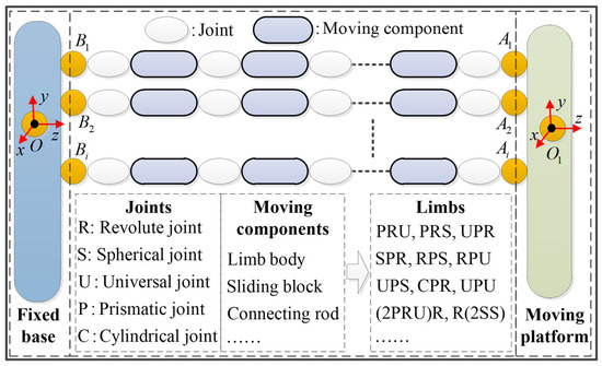
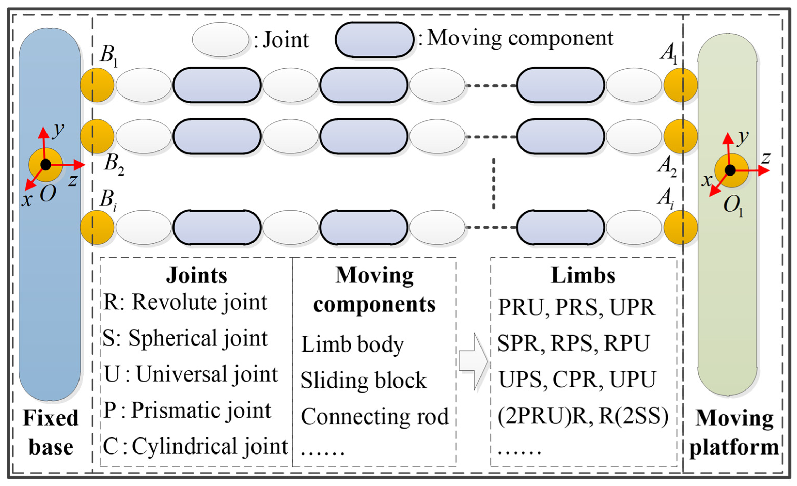
For a topological view, a parallel robot consists of a fixed base, a moving platform, and a group of limbs connecting the moving platform to the fixed base. An individual limb is composed of a set of moving components connected by joints. Each joint can be selected as a spherical joint (denoted as “S”), a universal joint (denoted as “U”), a cylindrical joint (denoted as “C”), a revolute joint (denoted as “R”), or a prismatic joint (denoted as “P”). The limbs can be expressed as the arrangement of joints from the fixed base to the moving platform, such as PRS, UPS, UPR, SPR, R(2SS), and so on. For clarity, Figure 1 demonstrates the schematic diagram of parallel robots.
Figure 1.
Schematic diagram of parallel robots.
As illustrated in Figure 1, some necessary definitions and coordinate systems are introduced. Bi and Ai represent geometric centers of the two joints attached to the fixed base and the moving platform in the ith limb, respectively. The points O and O1 are defined as the feature points (such as the geometric center) of polygons B1B2…Bi and A1A2…Ai (i = 1–nL), respectively. nL is the number of limbs. A global coordinate system O-xyz is attached at point O, while an instantaneous coordinate system O1-xyz is set at point O1 with its three axes remaining parallel to those of O-xyz. The stiffness model of such a robotic system has been established with a mature method in the existing studies, which yields a semi-analytical formulation of terminal rigidity as shown in Equation (1).
where K denotes the terminal stiffness matrix of a parallel robot. Ji (i = 1–nL) is the Jacobian matrix of the ith limb. KL,i (i = 1–nL) is the stiffness matrix of the ith limb. The detailed modeling process can be found in the existing literature of [17,18,19,20].
2.2. Index Construction
This subsection constructs a set of stiffness indices for evaluating the terminal rigidity of a parallel robot by transforming the stiffness matrix into a quantifiable metric. Subsequently, an intensity factor is formulated to reveal the effect of component compliance on terminal rigidity.
2.2.1. Stiffness Indices
To address the unit-induced inconsistent physical meaning, a stiffness metric based on the principle of virtual work is formulated to quantify the deformation resistance of parallel robots. Giving the stiffness matrix K of a parallel robot, the stiffness metric k can be formulated as shown in Equation (2).
where $F0 denotes a unit wrench imposed on the endpoint of the moving platform, while $ε0 is the corresponding deflection screw. C represents the compliance matrix of the parallel robot. $F0, $ε0 and K are all evaluated in the instantaneous coordinate system O1-xyz.
Physically, a larger value of k indicates a smaller deflection and a better anti-deformability of the parallel robot. The index k may be adopted as a local stiffness index to evaluate the terminal rigidity along/about the unit wrench $F0 at a given posture. Based on this foundation, six local stiffness indices are constructed to fully disclose the stiffness characteristics of parallel robots as formulated in Equation (3).
where kLx, kLy and kLz are three local linear stiffness indices that evaluate the terminal rigidity along the three axes of O1-xyz, respectively. kRx, kRy and kRz are three angular stiffness indices that evaluate the terminal rigidity about the three axes of O1-xyz, respectively. $F0,i (i = 1–6) is a unit wrench along and about the three axes of O1-xyz.
Based on the above definition, two global stiffness indices kgL and kgR are constructed, i.e., the two minimum values of the above local linear and angular stiffness indices throughout a task workspace. Intuitively, the two global indices kgL and kgR reflect the worst linear and the worst angular stiffness of parallel robots. By uniformly discretizing the task workspace, kgL and kgR can be approximately calculated by Equation (4).
where kLx,t, kLy,t and kLz,t (t = 1–nw) denote the three local linear stiffness indices at the tth discretized posture; kRx,t, kRy,t and kRz,t (t = 1–nw) denote the three local angular stiffness indices at the tth discretized posture; nw denotes the number of discretized postures of the task workspace.
2.2.2. Intensity Factor
The stiffness properties of parallel robots are governed by the compliance of their constituent components. Trial-and-error adjustment of partial structure parameters will be computationally inefficient and lack systematic guidance. The identification of sensitive components is a pragmatic strategy to navigate the high-dimensional design space in such robotic systems.
By referring to the definition of the local stiffness index, the equivalent stiffness coefficient kc is constructed to evaluate the component compliance about a given direction, as shown in Equation (5).
where ke is the (6-nf)-order interface stiffness matrix of the component that covers only the constrained axes. nf represents the degree of freedom. Jε is the constraint Jacobian matrix of the component.
For a linear system, the effect of an independent variable x on the dependent variable f (x) can be simply evaluated by a gain factor as shown in Equation (6).
For such a nonlinear mechanical system described in Equation (1), the relationship between the stiffness indices and component compliance exhibits inherent nonlinearity. No constant gain factor exists that can uniformly quantify the influence of the independent variable on the dependent variable. By accounting for the interval variation in the independent variable, an intensity factor (defined as the mean gain factor) is constructed to quantitatively reveal the impact of equivalent stiffness coefficients on the two global stiffness indices. The intensity factor ck can be expressed by Equation (7).
where nh denotes the given interval boundary of the equivalent stiffness coefficient. kc and kg,0 denote the initial equivalent stiffness coefficient of the component and its corresponding global linear/angular stiffness index of the parallel robot. kg,1 represents the iterative global stiffness index with the increase in kc. ck evaluates the average variations in the global stiffness index kg,0 with respect to component compliance kc with an interval of [−nh, nh].
For the sake of computational simplification, the interval of equivalent stiffness coefficients is uniformly divided into a set of nodes. Equation (7) can be approximatively calculated by Equation (8).
where h and th denote the increment of each node and the number of nodes. kg,1 represents an iterative global stiffness index with kc increased by h.
From the physical perspective, the intensity factor ck quantifies the influence of the equivalent stiffness coefficient kc on the global stiffness index. A larger ck indicates a greater influence of the stiffness coefficient on the terminal rigidity of parallel robots. By calculating and comparing the intensity factors of all stiffness coefficients, sensitive and insensitive coefficients may be sorted out rapidly. Consequently, structural parameters that significantly influence a sensitive coefficient are identified as sensitive parameters, while the remaining ones are classified as insensitive parameters.
2.3. Procedure of Rigidity Enhancement
The core principle of the rigidity enhancement is to enhance the terminal rigidity of parallel robots while maintaining or reducing their overall weight in the present study. This can be accomplished by upregulating the size of sensitivity-ranked components to boost terminal rigidity, and concurrently downregulating the size of insensitivity components, thereby optimizing the stiffness-to-weight ratio. It is worth noting that dimensional parameters should remain unchanged during the optimization procedure. This is because they affect the kinematic performance of parallel robots, which is typically determined during the dimension design stage.
The main procedures of rigidity enhancement for parallel robots can be summarized in the following steps:
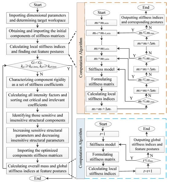
Step 1: Import the dimensional parameters of the parallel robot to carry out its position solution, and determine a target workspace within the researchable workspace.
Step 2: Obtain and import the initial component stiffness matrices by using finite element software, such as ANSYS 14.5.
Step 3: Substitute component stiffness matrices into a pre-established stiffness model to formulate the terminal stiffness matrix of the parallel robot.
Step 4: Calculate the local stiffness index and find out the feature postures with the worst terminal rigidity within the given task workspace. Herein, mi (i = 1–t) denotes a motion parameter describing the position or posture of the parallel robot, and t is the number of degrees of freedom. The computation algorithm uses a slice-partition search algorithm with increments of Δm1, Δm2,…, Δmt.
Step 5: Judge whether the parallel robot possesses a desirable stiffness without increasing the overall weight, i.e., kgL ≥ kgL,limit, kgR ≥ kgR,limit, and G1 < G0. Herein, kgL,limit and kgR,limit are two design thresholds of the global linear and angular stiffness indices, respectively. G0 and G1 denote the overall weight of the initial conceptual design and the enhanced design of the parallel robot. If the parallel robot satisfies those conditions, the design process is ceased. Otherwise, the following steps (Step 6–12) will be performed.
Step 6: Characterize the component rigidity as a set of quantized stiffness coefficients.
Step 7: Calculate intensity factors ck at the feature postures, with which the effect of each stiffness coefficient on the boundary of terminal rigidity is quantitatively evaluated to sort out sensitive and insensitive stiffness coefficients.
Step 8: Identify the sensitive and insensitive structural parameters that affect those sensitive and insensitive stiffness coefficients based on engineering insight.
Step 9: Adjust the structural features of components using the following way: increasing sensitive parameters to enhance their rigidity and decreasing insensitive parameters to reduce their weight.
Step 10: Recalculate and re-import the optimized component stiffness matrices with the aid of finite element software.
Step 11: Calculate the local stiffness indices at feature postures based on a formulated stiffness model to obtain the global stiffness indices. Herein, tmax is the number of feature postures in the initial conceptual design.
Step 12: Repeat Step 4 to Step 10 until the parallel robot satisfies the conditions of kgL ≥ kgL,limit, kgR ≥ kgR,limit, and G1 < G0.
To facilitate understanding and implementation, Figure 2 illustrates the flowchart of rigidity enhancement for a parallel robot.
Figure 2.
Flowchart of rigidity enhancement for parallel robots.
3. Application to a Parallel Machining Robot
In this section, the proposed rigidity enhancement methodology is applied to enhance the terminal rigidity of a novel redundantly actuated parallel machining robot.
3.1. Initial Conceptual Design and Kinematic Definition
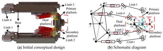
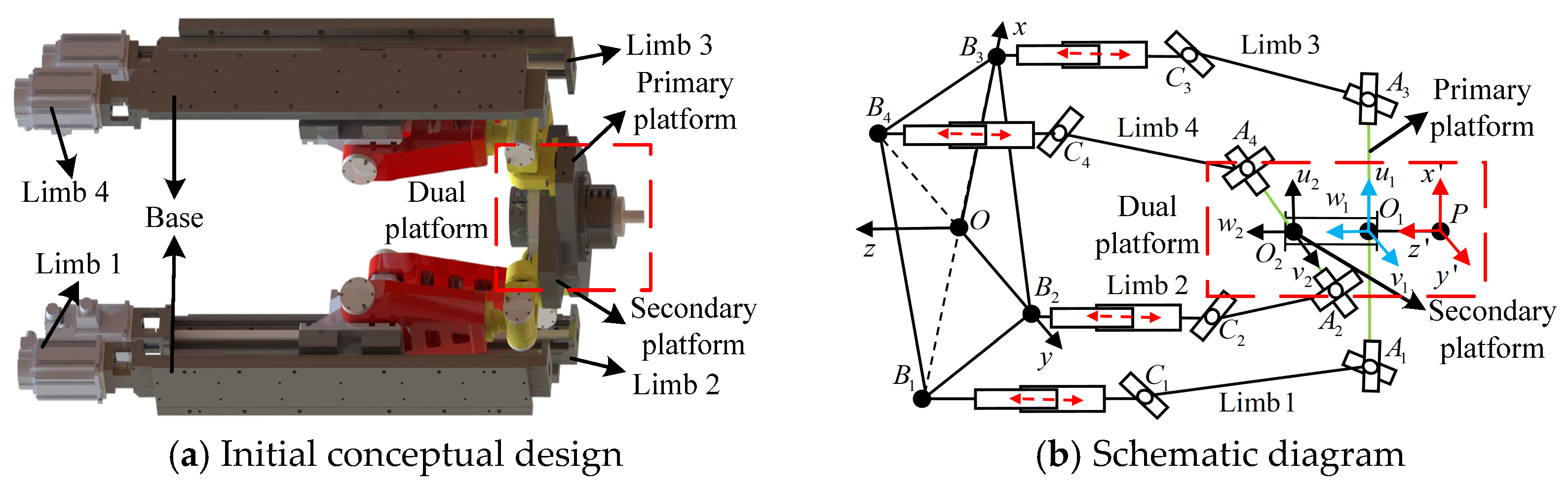
For clarity, the initial conceptual design and its schematic diagram of a novel redundantly actuated parallel machining robot (RAPMR) named Z4-RAPMR are depicted in Figure 3.
Figure 3.
Initial conceptual design and schematic diagram of the Z4-RAPMR.
As shown in Figure 3a, the Z4-RAPMR has a topology of 2PRU-(2PRU)R, which is composed of a fixed base, a dual platform, and four PRU limbs, denoted as Limb 1, Limb 2, Limb 3, and Limb 4. Each PRU limb contains an actuated prismatic joint, a revolute joint, and a universal joint. For the sake of performance symmetry, the four limbs are designed with identical structures and symmetrical arrangements. The dual platform consists of a primary platform, a revolute joint, and a secondary platform. The revolute joint connects the secondary platform to the primary platform. Specifically, the primary platform is connected to the fixed base by Limb 1 and Limb 3, while the secondary platform is connected to the fixed base by Limb 2 and Limb 4.
As shown in Figure 3b, Bi denotes the original point on the central axis of the ith prismatic joint. The quadrangle B1B2B3B4 is set as a quadrilateral. Its geometric center is defined as O. Ai represents the geometric center of the universal joint in the ith limb. The midpoints of segments A1A3 and A2A4 are defined as O1 and O2, respectively. Ci is the geometric center of the revolute joint in the ith limb. To be specific, the length of A1A3 is set as 515.5 mm. The length of B1B3 is set as 520 mm. The length of CiAi is set as 390 mm. The length of O1P is set as 267.5 mm.
In addition, some necessary coordinate systems are defined. A global coordinate system O-xyz is set at O, with its x-axis pointing to B3, y-axis pointing to B2, and z-axis satisfying the right-hand rule. Two instantaneous coordinate systems, P-x′y′z′ and O1-x′y′z′, are attached to P and O1 with their three axes remaining parallel to those of O-xyz. A local coordinate system O1-u1v1w1 is set at O1, with its u1 axis pointing to A3, its w1 axis perpendicular to A1A2 and A3A4, and its v1 axis satisfying the right-hand rule. A local coordinate system O2-u2v2w2 is set at O2, with its v2 axis pointing to A2, its w2 axis parallel to w1, and its v1 axis satisfying the right-hand rule.
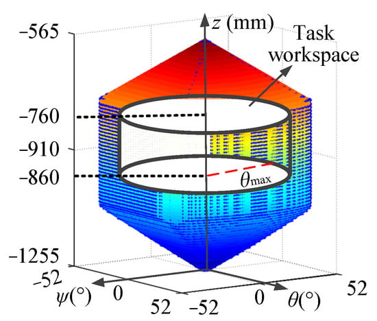
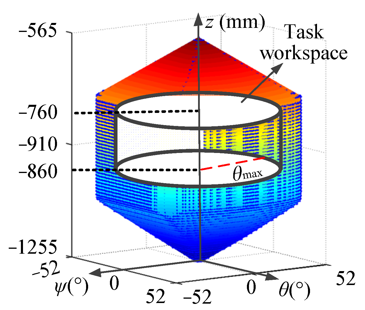
The Z4-RAPMR possesses two rotational and one translational motion capabilities [35]. The two rotational axes are respectively parallel to the v1 and u2 axes and go through point O, while the translational axis is parallel to the four actuated prismatic joints. By using Euler angles to describe the posture of the Z4-RAPMR, its reachable orientation workspace can be predicted and demonstrated in Figure 4 by a slice-partition search algorithm [35]. Herein, ψ and θ denote two ZYX Euler angles; z is a coordinate value of O1 along the z axis, measured in the frame O-xyz.
Figure 4.
Workspace of the Z4-RAPMR.
As shown in Figure 4, the orientation workspace of the Z4-RAPMR approximates a polyhedron, which is symmetric about the work planes of ψ = 0° and θ = 0°. This is consistent with the fact that those four identical PRU limbs are centro-symmetrically arranged. A cylindrical task workspace is selected with z = [−860, −760] mm and θmax = 45°. Referring to those parallel machining robots utilized for machining structure components [26,36], the target global linear and angular stiffness indices of the Z4-RAPMR are set as kgL,tgt = 3.5 × 10⁶ and kgR,tgt = 5.0 × 10⁵, respectively. Considering manufacturing deviation, a safety factor Q is introduced to obtain the thresholds of the global linear and angular stiffness indices as shown in Equation (9). As a case study, the safety factor Q is set as 1.1 in the present study.
3.2. Stiffness Model Formulation
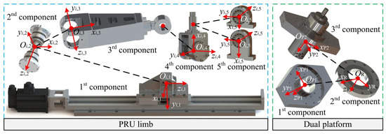
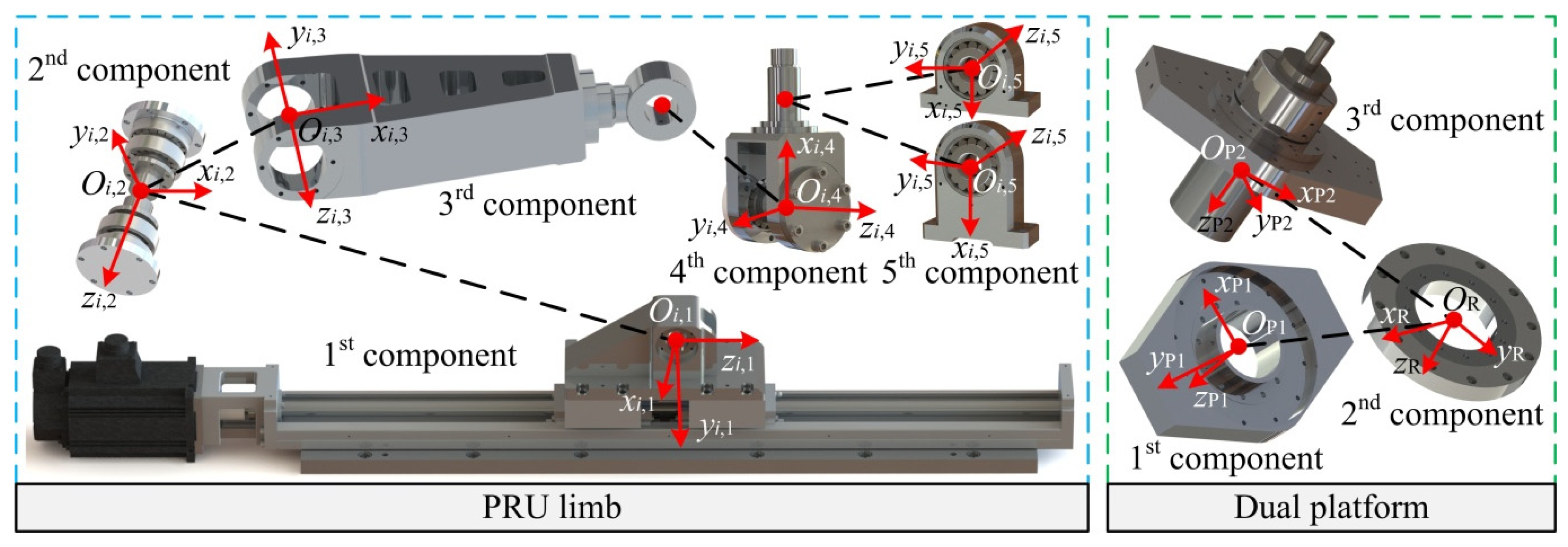
To facilitate derivation, the Z4-RAPMR is decomposed into a set of components as shown in Figure 5.
Figure 5.
Structure of decomposed components.
As shown in Figure 5, an individual PRU limb is further decomposed into five components. To be specific, the first component is a prismatic joint with a carriage assembly; the second component is a revolute joint; the third component is a middle link connecting the revolute joint and the universal joint; the fourth and the fifth components are the two rotational elements of the universal joint, respectively. The dual platform is further decomposed into three components. Herein, the first component is the secondary platform; the second component is the revolute joint connecting the primary platform and the secondary platform; the third component is the primary platform installed with a spindle. To evaluate the rigidity of each decomposed component, a body fixed coordinate system Oi,j-xi,jyi,jzi,j is attached to the jth component in the ith limb. Body fixed coordinate systems OP1-xP1yP1zP1, OR-xRyRzR and OP2-xP2yP2zP2 are attached to the first component, the second component and the third component of the dual platform, respectively.
To achieve a symmetrical performance, the same type of components is assumed to have identical structure and stiffness properties. Defining that ke,i,j and me,i,j are the stiffness matrix and the mass of the jth component in the ith limb, respectively. These stiffness matrices are all measured in their corresponding body fixed coordinate systems Oi,j-xi,jyi,jzi,j. ke,P2, ke,R and ke,P1 denote the stiffness matrices of the three components of the dual platform, measured in the body fixed frames OP2-xP2yP2zP2, OR-xRyRzR and OP1-xP1yP1zP1. me,P2, me,R and me,S denote their corresponding masses, respectively.
For a serial PRU limb, the stiffness matrix can be formulated as shown in Equation (10).
where KL,i is a third-order stiffness matrix of the ith PRU limb along/about its constraints. Ti,j denotes the adjoint transformation matrix of the body fixed frame Oi,j-xi,jyi,jzi,j with respect to the instantaneous coordinate system O1-x′y′z′. Jε,i,j is the constraint Jacobian matrix of the jth component of the ith limb, defined in the body fixed frame Oi,j-xi,jyi,jzi,j. Ji denotes the Jacobian matrix of the ith limb, which can be expressed as shown in Equation (11).
where $wa,L,i and $wc,L,i,j denote the unit wrench of actuation and the jth unit constraint wrenches of constraint produced by the ith PRU limb, respectively. ra,i is the position vector of Ai; sl,i denotes a unit vector from Ci to Ai. ra,i and sl,i are measured in the instantaneous coordinate system O1-x′y′z′.
By referring to Ref. [36], the stiffness matrix K(2PRU)R of a (2PRU)R compound limb can be given by Equation (12).
where TP2 and TR are the adjoint transformation matrices of the body fixed frames OP2-xP2yP2zP2 and OR-xRyRzR with respect to the instantaneous coordinate system O1-x′y′z′, respectively. Jε,P2 and Jε,R denote the constraint Jacobian matrices of the secondary platform and the revolute joint, measured in OP2-xP2yP2zP2 and OR-xRyRzR, respectively. Jε,2PRU and Jε,(2PRU)R are the constraint Jacobian matrices of two PRU limbs and a (2PRU)R compound limb, respectively. Equation (13) gives their expression.
where $wa,(2PRU)R,i and $wc,(2PRU)R denote the ith unit wrenches of actuation and the unit wrench of constraint produced by the (2PRU)R compound limb, respectively.
Since the primary platform is supported by Limb 1, Limb 3, and the (2PRU)R compound limb, the stiffness matrix KPM of a 2PRU-(2PRU)R parallel robot may be formulated as shown in Equation (14).
where KPM is measured in the instantaneous coordinate system O1-x′y′z′.
By considering the compliances of the primary platform and the spindle, the stiffness matrix of the overall Z4-RAPMR can be given by Equation (15).
where K is measured in the instantaneous coordinate system P-x′y′z′. TK and TP1 are the adjoint transformation matrices of the instantaneous coordinate system O1-x′y′z′ and the body fixed frame OP1-xP1yP1zP1 with respect to the instantaneous coordinate system P-x′y′z′, respectively. Jε,P1 is the Jacobian matrix of the primary platform measured in the body fixed frame OP1-xP1yP1zP1.
The above stiffness model has been presented and verified by Fang [37]. The experimental results demonstrated that the proposed stiffness model possesses a satisfactory computation accuracy, thus can be used for the stiffness prediction as well as evaluation for the Z4-RAPMR.
3.3. Stiffness Intensity Analysis
Predictably, global stiffness indices and intensity factor calculations will take a huge amount of computation and a lot of time. Existing studies [21,22,23,38] have demonstrated that neglecting the off-diagonal elements in the stiffness matrix of components may not significantly affect the overall stiffness computation. The marginal accuracy loss incurred by this diagonal assumption is outweighed by a substantial gain in computational efficiency. This is particularly valuable for global stiffness evaluation and fast iterative analysis of parallel robots, where precise stiffness analysis results are not required. Given this trade-off, each component is simplified into (6-nf) linear and angular virtual lumped springs with equivalent stiffness coefficients in the present study. Herein, nf denotes the degree of freedom of the component. Based on the above simplification, the stiffness matrix ke,i of the ith component can be expressed as a (6-nf)-order diagonal matrix, as shown in Equation (16).
where kx,i, ky,i and kz,i denote the equivalent linear stiffness coefficients of the ith component along the axes of its body fixed coordinate system; kw1,i and kw(3−nf),i denote the equivalent angular stiffness coefficients of the ith component about the constraint axes of its body fixed coordinate system. As demonstrated in Figure 5, the Z4-RAPMR has nine components with 49 equivalent stiffness coefficients. Those stiffness coefficients can be calculated by Equation (5). By using the proposed algorithm, as shown in Figure 2, the two global stiffness indices can be obtained as kgL = 3.063 × 10⁶ and kgR = 4.989 × 10⁵, respectively. The worst terminal rigidity of the Z4-RAPMR occurs at the boundaries of the task workspace, i.e., the postures of (ψ = ±45°, θ = 0°, z = −860 mm) and (ψ = 0°, θ = ±45°, z = −860 mm).
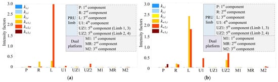
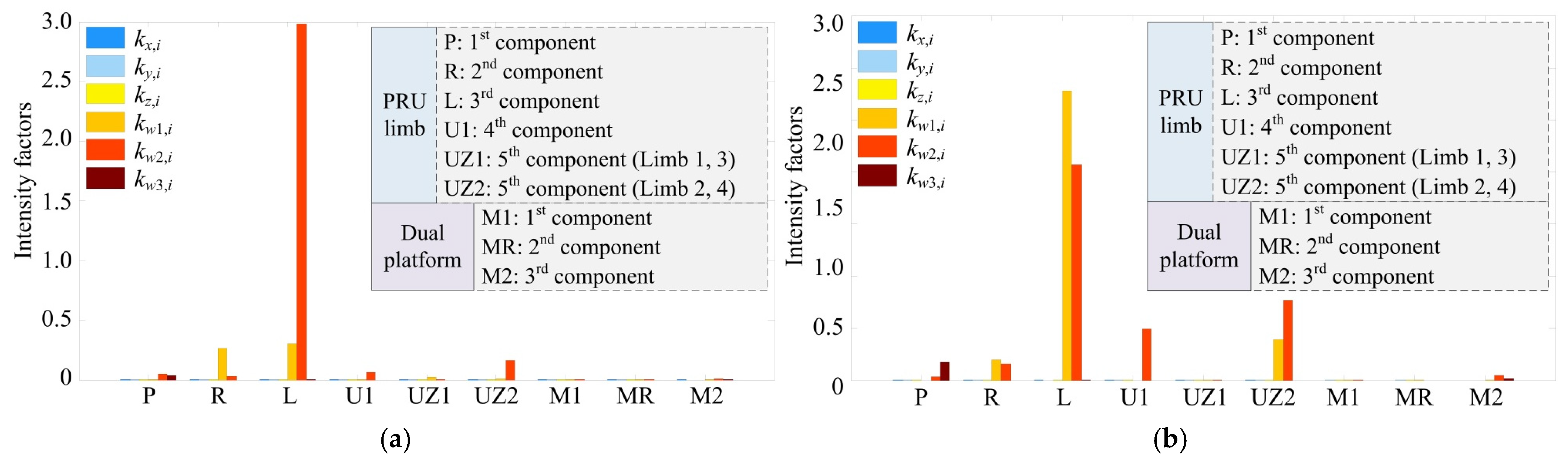
By adopting the constructed intensity factor as shown in Equation (7), the effect of those 49 equivalent stiffness coefficients on global stiffness indices can be evaluated quantitatively. By setting each equivalent stiffness coefficient ke to vary within an interval of [(1–10%)ke, (1 + 10%)ke], the intensity factors can be calculated, as depicted in Figure 6. Herein, kx,i, ky,i and kz,i denote three linear equivalent stiffness coefficients, while kw1,i, kw1,i and kw3,i denote three angular equivalent stiffness coefficients of the ith component. These coefficients are measured in the body fixed frame.
Figure 6.
Intensity factors calculating results for 49 equivalent stiffness coefficients. (a) Intensity factors with respect to global linear stiffness index. (b) Intensity factors with respect to global angular stiffness index.
As shown in Figure 6, these equivalent stiffness coefficients kw3,1, kw1,2, kw2,2, kw1,3, kw2,3, kw2,4, kw1,6 and kw2,6 have relatively larger intensity factors. This indicates that these eight equivalent stiffness coefficients and their corresponding component compliance have significant impacts on the terminal rigidity of the Z4-RAPMR, which are identified as sensitive stiffness coefficients. The remaining 41 stiffness coefficients will be identified as insensitive stiffness coefficients.
3.4. Rigidity Enhancement and Discussion
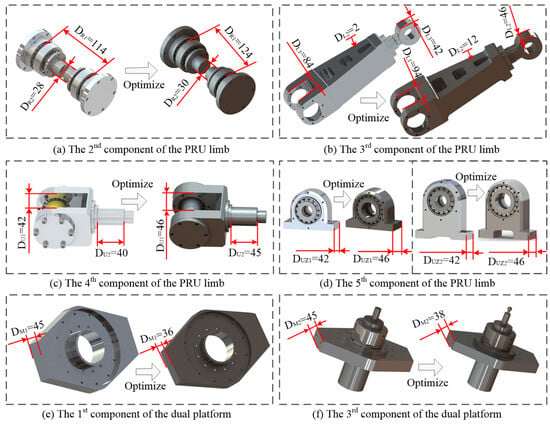
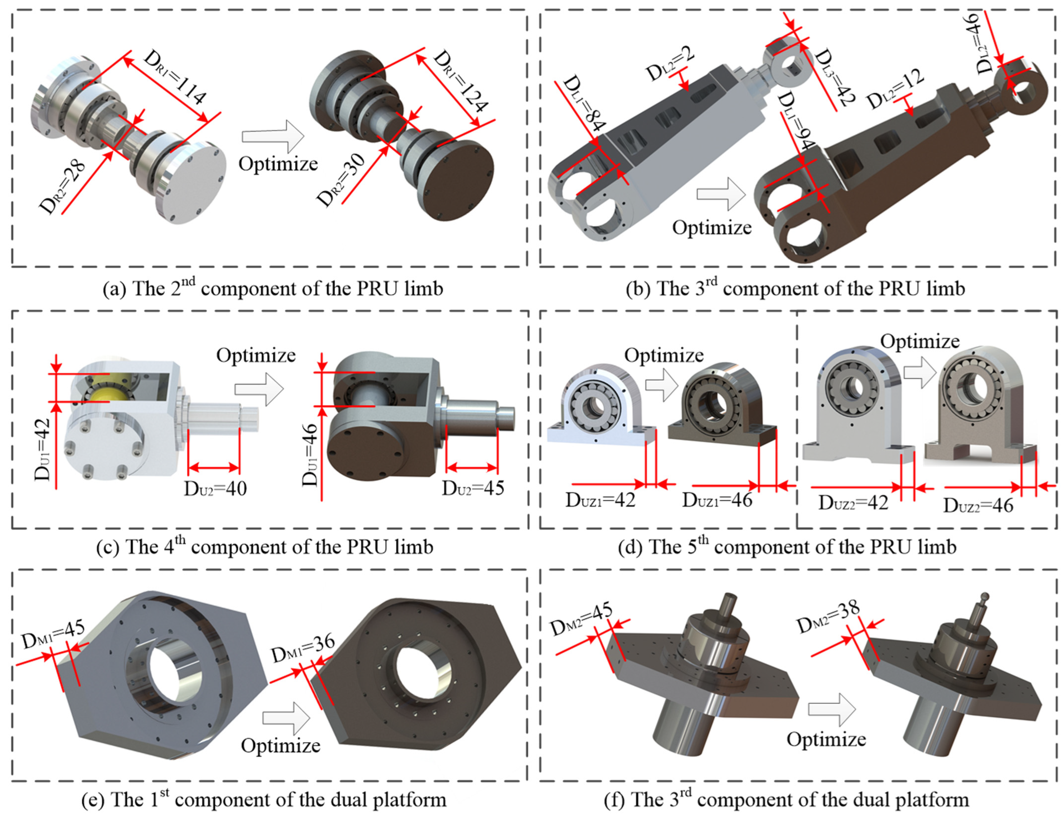
According to the intensity factor analysis results, the structural parameter optimization of the Z4-RAPMR is carried out at the component level as recorded in this subsection. Herein, the first component of the PRU limb and the second component of the dual platform are two standard components. The structural parameter optimization is implemented by following the underlying idea: increasing the sensitive parameters that exert a significant influence on the eight sensitive stiffness coefficients for high rigidity; decreasing the insensitive parameters that drastically increase mass but do not significantly affect terminal rigidity. For clarity, Figure 7 illustrates the optimization results of the Z4-RAPMR.
Figure 7.
Components optimizing for the Z4-RAPMR.
As shown in Figure 7a, structural parameters DR1 and DR2 are increased from 114 mm and 28 mm to 124 mm and 30 mm in the PRU limb, respectively. These adjustments are to enhance the angular stiffness of the second component about the axes of xi,2 and yi,2 (i = 1–4). As shown in Figure 7b, the third component of the PRU limb has great mass. Its insensitive structural parameters DL1 and DL3 are increased from 84 mm and 42 mm to 94 mm and 46 mm, respectively. These adjustments are to enhance the angular stiffness of the 3rd component about the axes of xi,3 and yi,3. In addition, structural parameter DL2 is increased from 2 mm to 12 mm for a mass reduction. As shown in Figure 7c, structural parameters DU1 and DU2 are increased from 42 mm and 40 mm to 46 mm and 45 mm in the PRU limb, respectively. These adjustments are to enhance the angular stiffness of the fourth component about the axis of yi,4. As shown in Figure 7d, the structural parameter DUZ1/DUZ2 is increased from 42 mm to 46 mm in the PRU limb. The adjustment is to enhance the angular stiffness of the fifth component about the axes of xi,5 and yi,5. As shown in Figure 7e,f, the first and the third components of the dual platform have greater masses. Their insensitive structural parameters DM1 and DM2 are decreased from 45 mm and 45 mm to 36 mm and 38 mm, respectively. These adjustments are to reduce the mass of the dual platform.
Table 1 demonstrates the comparison between the initial conceptual design and the enhanced design of the Z4-RAPMR.
Table 1.
Comparison between the initial and the enhanced scheme of the Z4-RAPMR.
As shown in Table 1, after using the proposed rigidity enhancement methodology, the overall weight of the Z4-RAPMR is reduced from 328.49 kg to 310.13 kg with a reduction rate of 5.6%. Its linear global stiffness index kgL is increased from 3.063 × 10⁶ to 4.023 × 10⁶ with a growth rate of 31.3%. Its angular global stiffness index kgR is increased from 4.989 × 10⁵ to 5.786 × 10⁵ with a growth rate of 16%. This result supports that the proposed rigidity enhancement methodology is effective in improving the stiffness of parallel robots without increasing the overall weight.
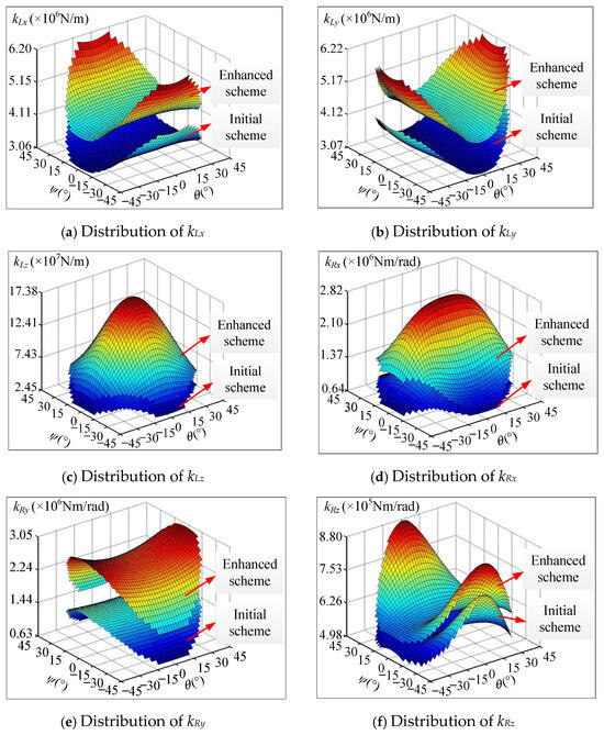
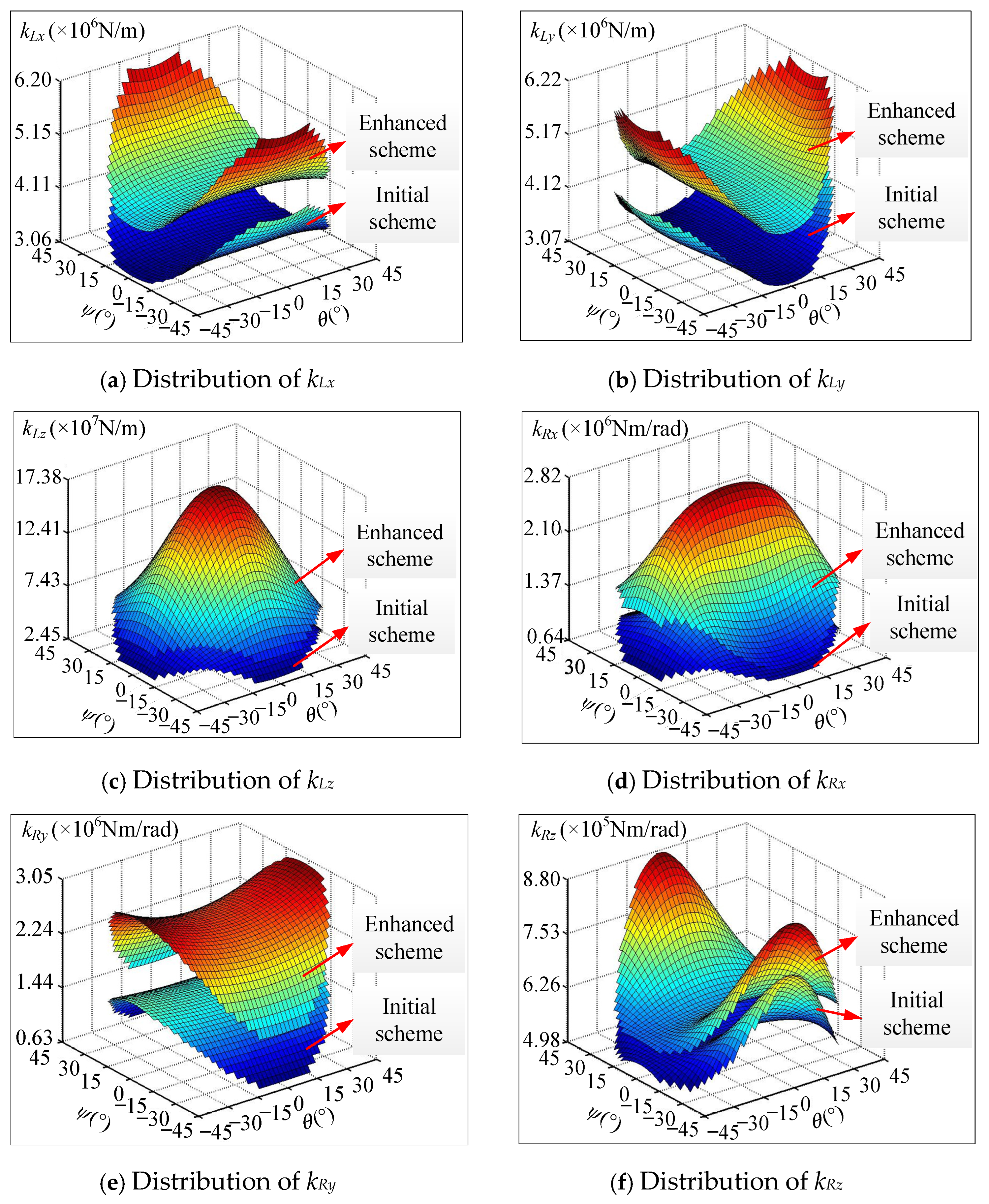
To further disclose the performance advantage of the enhanced Z4-RAPMR, a comparison study on the local stiffness properties between the initial scheme and the enhanced scheme is carried out. Without loss of generality, the distributions of six local stiffness indices over the work-plane of z = −860 mm are analyzed and shown in Figure 8.
Figure 8.
Distributions of six local stiffness indices of the Z4-RAPMR.
As shown in Figure 8, the terminal rigidity of the Z4-RAPMR is strongly position-dependent. The distributions of its six local stiffness indices are simultaneously symmetric with respect to the work planes of ψ = 0° and θ = 0°, respectively. This is consistent with the structural features that four PRU limbs are designed with identical structures and arranged centro-symmetrically. Moreover, these six local stiffness indices of the enhanced scheme are significantly larger than those of the initial scheme throughout the whole work plane. This manifests that the proposed rigidity enhancement methodology is effective in improving the stiffness of parallel robots.
In addition, the proposed rigidity enhancement methodology can be extended to other parallel robots by simply replacing the stiffness model, which is associated with the specific topology and the structural characteristics.
4. Prototype Fabrication and Experimental Validation
4.1. Prototype Fabrication
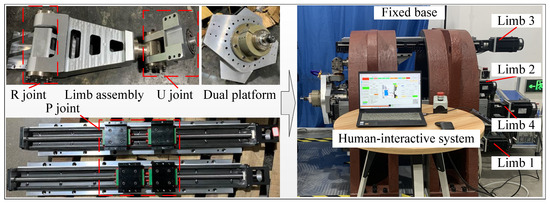
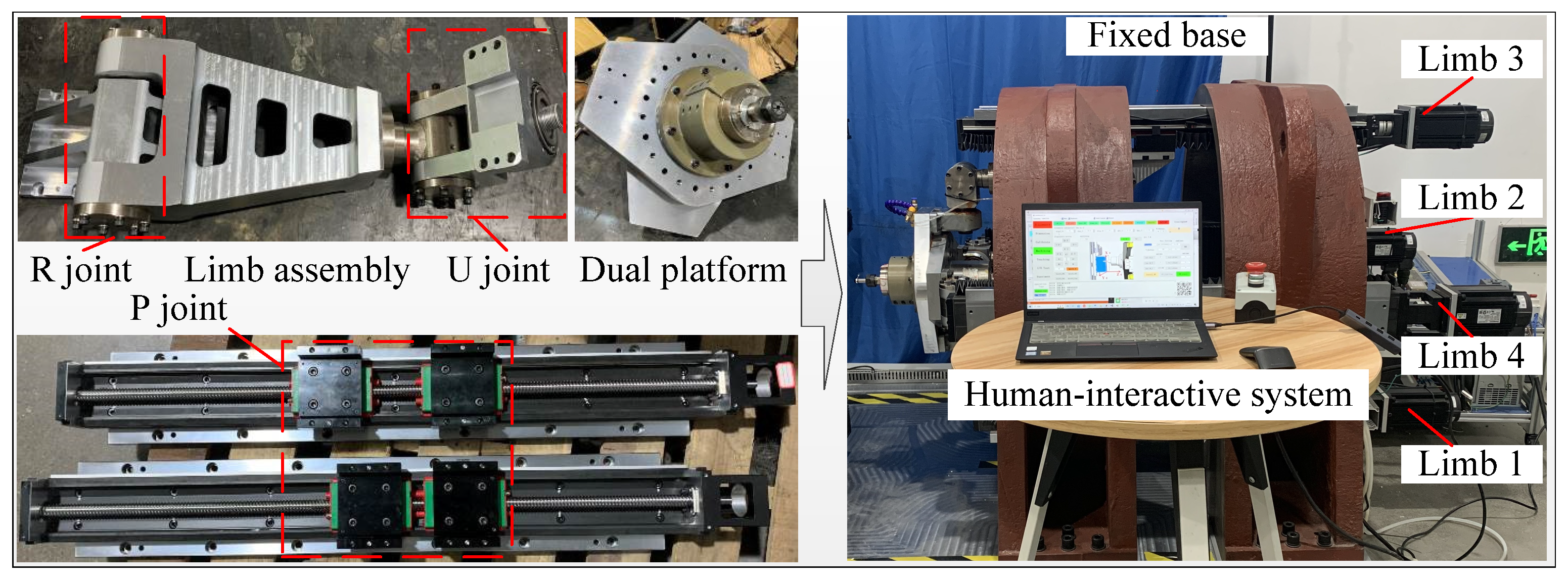
Based on the aforementioned enhanced scheme, a laboratory prototype of the Z4-RAPMR is hierarchically fabricated, as shown in Figure 9.
Figure 9.
Fabrication of a laboratory prototype.
As shown in Figure 9, the fabricated prototype is constructed by assembling four PRU limbs and a dual platform to the fixed base. Herein, an individual PRU limb consists of a prismatic joint and a limb assembly. The prismatic joint assembly adopts a commercial linear motion module, which is actuated by a servo motor. The limb assembly contains a revolute joint and a universal joint. The assembling process can be divided into the following three steps: (1) Assemble four prismatic joints to the fixed base symmetrically and parallelly. (2) Connect a limb assembly to the prismatic joint, in which the revolute joint is perpendicular to the movement axis. (3) Install the dual platform to the four limb assemblies by universal joints. Actuated by the four PRU limbs, the dual platform will achieve two rotational and one translational motion to adjust the postures of the spindle.
The specifications of the measurement instruments used in the stiffness tests are listed in Table 2.
Table 2.
The specifications of the measurement instruments used in the stiffness tests.
4.2. Stiffness Test and Validation
To verify the effectiveness of the proposed rigidity enhancement methodology, a set of stiffness tests is carried out on the fabricated prototype. The underlying idea is to make a comparison study between the experimental stiffness indices and the target global stiffness index. This idea can be implemented through the following three steps.
Step 1: Construct an experiment system for stiffness testing and select a set of reasonable measurement configurations to demonstrate the worst terminal rigidity of the Z4-RAPMR.
Step 2: Measure and obtain the load-deflection data by using the established experiment system, based on which the stiffness indices of the laboratory prototype are calculated.
Step 3: Compare the experimental stiffness indices with the target stiffness index to verify the effectiveness of the proposed rigidity enhancement methodology.
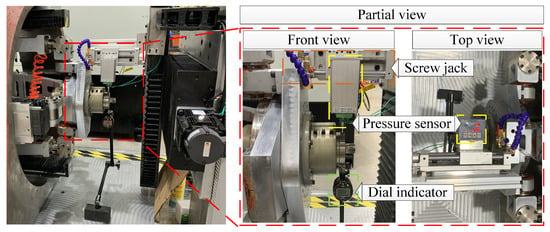
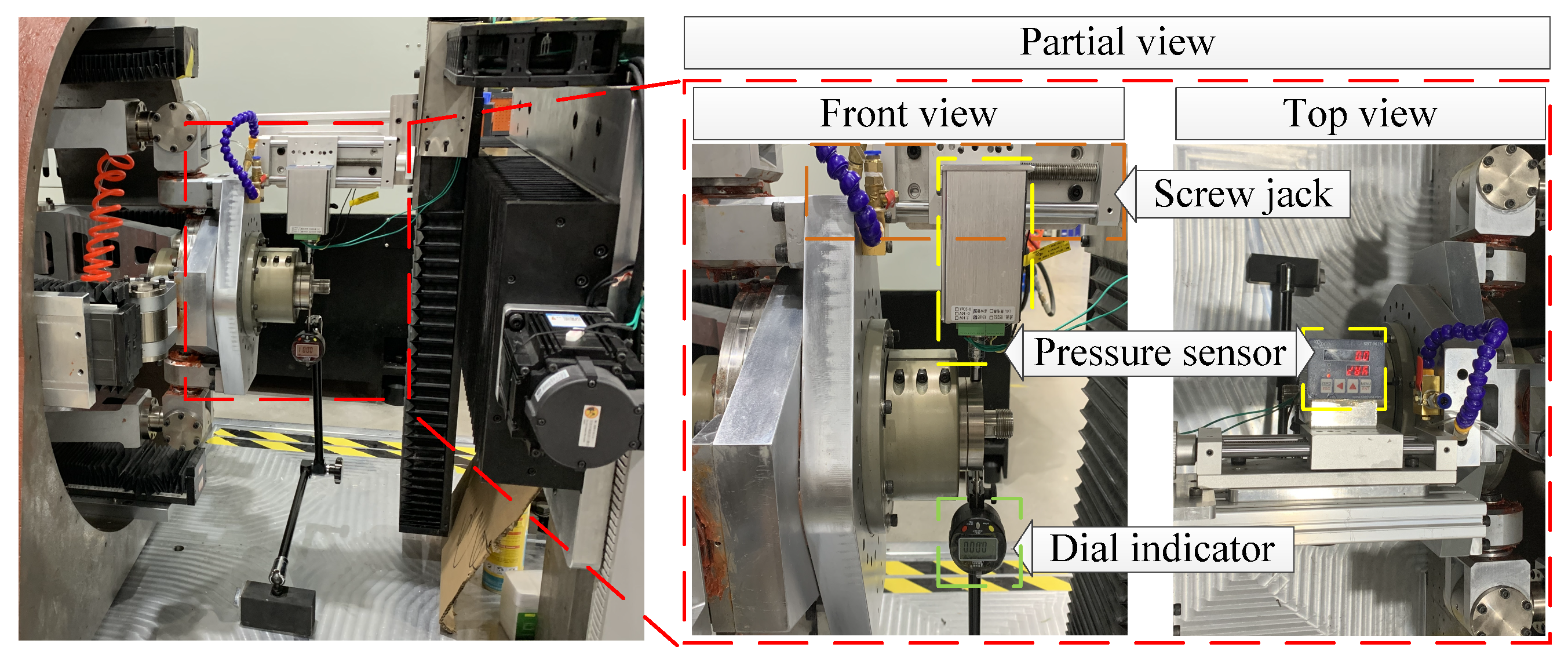
For clarity, Figure 10 depicts the full experimental setup of stiffness testing.
Figure 10.
Stiffness testing set-up.
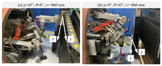
As depicted in Figure 10, the screw jack is used to apply force to the Z4-RAPMR, while the pressure sensor is adopted to measure its magnitude. Moreover, a dial indicator is installed in a bracket to measure the deflection under pressure. The proposed rigidity enhancement methodology adopts global stiffness indices as its design objective, thereby ensuring the worst-case terminal rigidity of parallel robots. Consequently, the stiffness testing in the present study will focus specifically on those configurations where global stiffness indices are observed. As illustrated in Figure 8, the global linear stiffness index is located at the extreme postures of either (ψ = ±45°, θ = 0°, z = −860 mm) or (ψ = 0°, θ = ±45°, z = −860 mm). For this purpose, these two extreme configurations with maximum θ and ψ were selected to validate the worst-case scenario as depicted in Figure 11.
Figure 11.
Stiffness testing for two extreme configurations.
As shown in Figure 11, the load-deflection data of the Z4-RAPMR can be obtained by applying a set of forces to the endpoint. To achieve satisfactory testing accuracy, a preloading force is applied to eliminate joint clearance during the experimental testing. The preloading force and its induced deflection are not accounted for in the present experiments. At each experimental configuration, the applied force was increased gradually, during which its magnitude and the terminal deflection of the parallel robot were measured and recorded. The work W done by the applied force can be expressed as Equation (17).
where F and δ are the applied force and its induced deflection, respectively. ε and $F denote the magnitude and the unit wrench of the applied force, respectively. δ is the deflection along the applied force. Substituting Equation (1) into Equation (17), the local stiffness index may be calculated as shown in Equation (18).
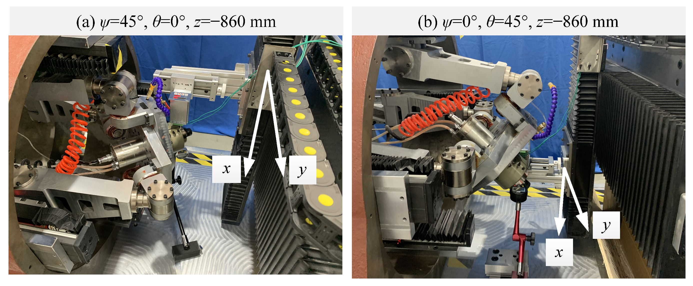
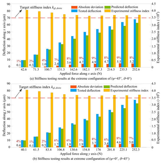
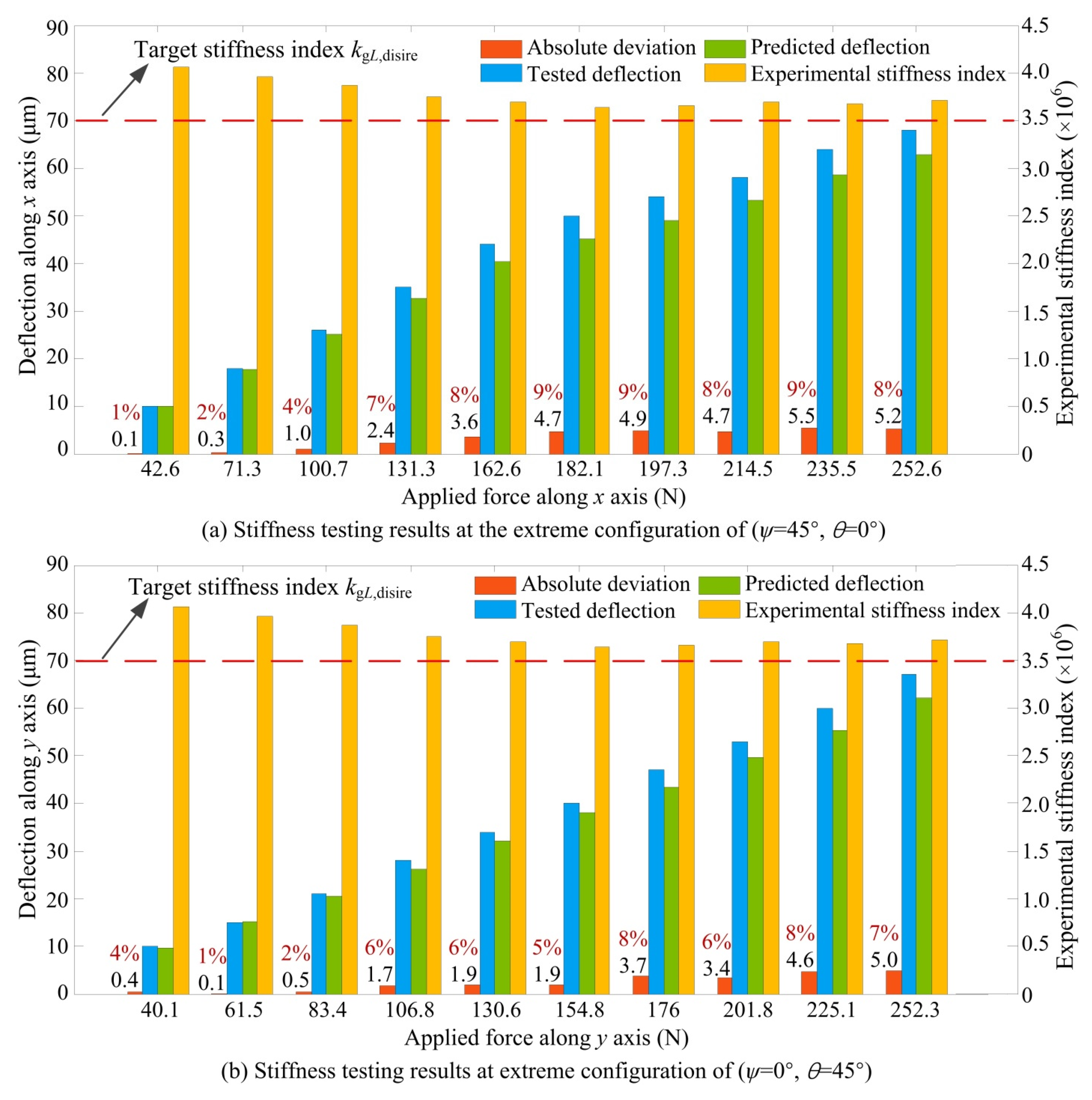
Following the experimental tests, the experimental stiffness indices were compared with the target global stiffness index as illustrated in Figure 12. Herein, “Predicted deflection” is calculated by the established stiffness model, while “Tested deflection” is obtained by the dial indicator directly. “Absolute deviation” denotes the absolute deviation between “Tested deflection” and “Predicted deflection”. “Experimental stiffness index” is calculated by Equation (18).
Figure 12.
Stiffness testing results for the two extreme configurations.
As can be seen clearly from Figure 12, the experimental stiffness indices show a slight fluctuation with variation in applied force. This may indicate that the fabricated Z4-RAPMR possesses a stable terminal rigidity, and the stiffness testing is reasonable. Such a slight fluctuation may be caused by non-ideal contact and inhomogeneous dampers existing in the joints. Compared with the target global stiffness index kgL,tgt, the experimental stiffness indices all have larger values. The results support that the proposed rigidity enhancement methodology is effective in improving the terminal rigidity of parallel robots with a satisfying global stiffness index. Additionally, it is worth noting that the terminal deflections obtained from the experimental tests are larger than those predicted by the established stiffness model. Their largest absolute deviation is 5.45 μm with a relative error under 10%. In other words, the established stiffness model may overestimate the stiffness indices of the parallel robot. The main reason lies in the fact that the established stiffness model makes some assumptions and approximations: (1) the components are assumed to be linearly elastic; (2) all manufacturing deviations and joint clearances are neglected. Such stiffness overestimation can be rectified through calibration in actual engineering applications, thereby ensuring more accurate performance predictions. So, it is important to set a reasonable safety factor for the target global stiffness index in the design stage.
5. Conclusions
The main findings of this investigation are summarized as follows:
- (1)
- A set of local and global stiffness indices is constructed to evaluate the terminal rigidity of parallel robots across their task workspace. Building on this foundation, an intensity factor is subsequently introduced to quantitatively reveal the effect of component compliance on the terminal rigidity of a parallel robot.
- (2)
- A practical and highly efficient methodology is developed to enhance the terminal rigidity of parallel robots while maintaining or reducing their overall weight. This is attributed to the use of an intensity factor to quickly identify sensitive and insensitive stiffness coefficients, thereby enabling an optimal balance between high rigidity and low weight.
- (3)
- To demonstrate its practical application in designing high-rigidity parallel robots, the proposed rigidity enhancement methodology is applied to a novel Z4-RAPMR. The implementation leads to 31.3% and 16% increases in global linear and angular stiffness indices, while achieving a 5.6% reduction in overall weight.
- (4)
- A stiffness testing set-up is developed and employed to conduct a set of terminal rigidity tests on a laboratory prototype. The testing results revealed that the experimental stiffness indices at two extreme configurations surpassed the predefined global stiffness target. This suggests that the enhanced Z4-RAPMR may possess a satisfactory terminal rigidity throughout its target workspace. This successful application verifies that the proposed methodology can effectively enhance the terminal rigidity of parallel robots.
- (5)
- It is worth noting that the present study does not account for potential stiffness degradation due to non-ideal contacts or inhomogeneous dampers. Future work will therefore focus on investigating the effects of joint clearance, bearing preload, and overconstraint on the terminal rigidity of parallel robots.
Author Contributions
Conceptualization, H.F. and J.Z.; methodology, H.F. and J.W.; software, J.L. and Y.N.; validation, J.L., S.G. and H.F.; formal analysis, H.F., Y.N. and J.L.; writing—review and editing, H.F., S.G. and J.Z.; project administration, J.Z.; funding acquisition, H.F., S.G. and J.Z. All authors have read and agreed to the published version of the manuscript.
Funding
This research was funded by the financial support from the National Natural Science Foundation of China [Grant No. 52375009], the Natural Science Foundation of Fujian Province [Grant Nos. 2024J08147, 2024J02007, and 2024J08133].
Data Availability Statement
All required data are included in the text and are available upon request from the corresponding author.
Conflicts of Interest
The authors declare that they have no known competing financial interests or personal relationships that could have appeared to influence the work reported in this paper.
References
- Cui, Y.F.; An, X.; Lin, Z.H.; Guo, Z.B.; Liu, X.J.; Zhao, H.C. Design and implementation of an underactuated gripper with enhanced shape adaptability and lateral stiffness through semi-active multi-degree-of-freedom endoskeletons. Int. J. Robot. Res. 2023, 43, 873–896. [Google Scholar] [CrossRef] [Scilit]
- Park, S.; Kim, J.; Park, J.; Burgner-Kahrs, J.; Noh, G. Design of patterns in tubular robots using DNN-metaheuristics optimization. Int. J. Mech. Sci. 2023, 251, 108352. [Google Scholar] [CrossRef] [Scilit]
- Xie, Y.; Yi, W.M.; Feng, Z.Q.; Yao, J.T.; Zhao, Y.S. Design and motion planning of a 7-DOF assembly robot with heavy load in spacecraft module. Robot. Comput.-Integr. Manuf. 2024, 86, 102645. [Google Scholar]
- Cheng, P.; Cao, W.; Liu, D.G.; Cui, J.; Lai, J.P. A Novel Delta-Like Parallel Robot with Three Translations and Two Pitch Rotations for Peg-in-Hole Assembly. J. Mech. Robot. 2025, 17, 021014. [Google Scholar] [CrossRef] [Scilit]
- González, M.; Rodríguez, A.; López-Saratxaga, U.; Pereira, O.; de Lacalle, L.N.L. Adaptive edge finishing process on distorted features through robot-assisted computer vision. J. Manuf. Syst. 2024, 74, 41–54. [Google Scholar] [CrossRef] [Scilit]
- Wang, S.J.; Feng, W.; Wang, W.J.; Liu, J.Y.; Yong, D.; Li, T.J. Hyper-redundant hybrid manipulator modeling method. Int. J. Mech. Sci. 2025, 301, 110421. [Google Scholar] [CrossRef] [Scilit]
- Russo, M.; Zhang, D.; Liu, X.J.; Xie, Z.H. A review of parallel kinematic machine tools: Design, modeling, and applications. Int. J. Mach. Tools Manuf. 2024, 196, 104118. [Google Scholar] [CrossRef] [Scilit]
- Shen, H.P.; Li, J.; Li, T.; Kong, X.C.; Ye, P.D.; Zhu, W. A New Method for Motion-Decoupling Identification of Parallel Mechanisms. J. Mech. Robot. 2025, 17, 081004. [Google Scholar] [CrossRef] [Scilit]
- Abdur, R.; Cesare, S.; Bashar, E.K. A Novel Walking Parallel Robot for On-Structure Three-Axis Machining of Large Structures. J. Mech. Robot. 2023, 15, 061016. [Google Scholar]
- Fajardo-Pruna, M.; López-Estrada, L.; Pérez, H.; Diez, E.; Vizán, A. Analysis of a single-edge micro cutting process in a hybrid parallel-serial machine tool. Int. J. Mech. Sci. 2019, 151, 222–235. [Google Scholar] [CrossRef] [Scilit]
- Wang, L.P.; Li, M.Y.; Yu, G.; Li, W.T.; Kong, X.Y. Kinematic calibration method with high measurement efficiency and robust identification for hybrid machine tools. Chin. J. Aeronaut. 2024, 37, 468–482. [Google Scholar] [CrossRef] [Scilit]
- Yang, S.F.; Dai, J.S.; Jin, Y.; Fu, R. Finite displacement screw-based group analysis of 3PRS parallel mechanisms. Mech. Mach. Theory 2022, 171, 104727. [Google Scholar] [CrossRef] [Scilit]
- Farooq, S.S.; Baqai, A.A.; Shah, M.F. Optimal design of tricept parallel manipulator with particle swarm optimization using performance parameters. J. Eng. Res. 2021, 9, 278–295. [Google Scholar] [CrossRef] [Scilit]
- Dong, C.L.; Liu, H.T.; Huang, T.; Chetwynd, D.G. A Screw Theory-Based Semi-Analytical Approach for Elastodynamics of the Tricept Robot. J. Mech. Robot. 2022, 11, 031005. [Google Scholar] [CrossRef] [Scilit]
- López-Custodio, P.C.; Fu, R.; Dai, J.S.; Jin, Y. Compliance model of Exechon manipulators with an offset wrist. Mech. Mach. Theory 2021, 167, 104558. [Google Scholar] [CrossRef] [Scilit]
- Shen, F.Y.; Yang, S.F.; Wang, H.Y.; Dai, J.S. Twist and finite twist analysis of 2UPR-SPR parallel mechanism based upon screw theory. Mech. Mach. Theory 2023, 184, 105276. [Google Scholar] [CrossRef] [Scilit]
- Liu, H.T.; Huang, T.; Chetwynd, D.G.; Kecskemethy, A. Stiffness Modeling of Parallel Mechanisms at Limb and Joint/Link Levels. IEEE Trans. Robot. 2017, 33, 734–741. [Google Scholar] [CrossRef] [Scilit]
- Fang, H.L.; Tang, T.F.; He, Z.; Zhang, J. Evaluation on redundancy-induced rigidity enhancement of a parallel manipulator. J. Mech. Robot. 2023, 15, 041009. [Google Scholar] [CrossRef] [Scilit]
- Yue, W.; Liu, H.T.; Huang, T. An Approach for Predicting Stiffness of a 5-DOF Hybrid Robot for Friction Stir Welding. Mech. Mach. Theory 2022, 175, 104941. [Google Scholar] [CrossRef] [Scilit]
- Zhang, S.S.; Zhang, L.S. Stiffness Modeling and Deformation Analysis of Parallel Manipulators Based on the Principal Axes Decomposition of Compliance Matrices. J. Mech. Robot. 2023, 16, 041001. [Google Scholar] [CrossRef] [Scilit]
- He, Y.; Xie, F.; Liu, X.J.; Xie, Z.; Zhao, H.; Yue, Y.; Li, M. Stiffness-performance-based redundant motion planning of a hybrid machining robot. Machines 2022, 10, 1157. [Google Scholar] [CrossRef] [Scilit]
- Zhao, Y.; Jin, Y.; Zhang, J. Kinetostatic Modeling and Analysis of an Exechon PKM Module. J. Mech. Eng. 2016, 29, 33–44. [Google Scholar]
- Zhang, J.; Zhao, Y.Q.; Jin, Y. Kinetostatic-Model-Based Stiffness Analysis of Exechon PKM. Robot. Comput.-Integr. Manuf. 2016, 37, 208–220. [Google Scholar] [CrossRef] [Scilit]
- Yan, S.J.; Ong, S.K.; Nee, A.Y.C. Stiffness analysis of parallelogram-type parallel manipulators using a strain energy method. Robot. Comput.-Integr. Manuf. 2016, 37, 13–22. [Google Scholar] [CrossRef] [Scilit]
- Yang, C.; Li, Q.C.; Chen, Q.H.; Xu, L.M. Elastostatic stiffness modeling of overconstrained parallel manipulators. Mech. Mach. Theory 2017, 122, 58–74. [Google Scholar] [CrossRef] [Scilit]
- Sun, T.; Lian, B.B. Stiffness and mass optimization of parallel kinematic machine. Mech. Mach. Theory 2018, 120, 73–88. [Google Scholar] [CrossRef] [Scilit]
- Yang, C.; Li, Q.C.; Chen, Q.H. Analytical elastostatic stiffness modeling of parallel manipulators considering the compliance of the link and joint. Appl. Math. Model. 2020, 78, 322–349. [Google Scholar] [CrossRef] [Scilit]
- Li, Y.G.; Liu, H.T.; Zhao, X.M.; Huang, T.; Chetwynd, D.G. Design of a 3-DOF PKM module for large structural component machining. Mech. Mach. Theory 2010, 45, 941–954. [Google Scholar] [CrossRef] [Scilit]
- Carbone, G.; Ceccarelli, M. Comparison of indices for stiffness performance evaluation. Front. Mech. Eng. 2010, 5, 270–278. [Google Scholar] [CrossRef] [Scilit]
- Vu, L.N.; Kou, C.H. An analytical stiffness method for spring-articulated planar serial or quasi-serial manipulators under gravity and an arbitrary load. Mech. Mach. Theory 2019, 137, 108–126. [Google Scholar]
- Courteille, E.; Deblaise, D.; Maurine, P. Design optimization of a Delta-like parallel robot through global stiffness performance evaluation. In Proceedings of the International Conference on Intelligent Robots and Systems, Saint-Louis, MO, USA, 10–15 October 2009; IEEE: Piscataway, NJ, USA, 2009; pp. 5159–5166. [Google Scholar]
- Ceccarelli, M.; Carbone, G. A stiffness analysis for CaPaMan (cassino parallel manipula-tor). Mech. Mach. Theory 2002, 37, 427–439. [Google Scholar] [CrossRef] [Scilit]
- Wang, M.X.; Liu, H.T.; Huang, T.; Chetwynd, D.G. Compliance analysis of a 3-SPR parallel mechanism with consideration of gravity. Mech. Mach. Theory 2015, 84, 99–112. [Google Scholar] [CrossRef] [Scilit]
- Fan, S.; Fan, S.W.; Lan, W.B.; Song, G.K. A new approach to enhance the stiffness of heavy-load parallel robots by means of the component selection. Robot. Comput.-Integr. Manuf. 2020, 61, 101834. [Google Scholar] [CrossRef] [Scilit]
- Fang, H.L.; Tang, T.F.; He, Z.; Liu, Y.C.; Zhang, J. A novel hybrid machine tool integrating a symmetrical redundantly actuated parallel mechanism: Design, kinematics, prototype and experiment. Mech. Mach. Theory 2022, 176, 105013. [Google Scholar] [CrossRef] [Scilit]
- Wang, M.; Song, Y.M.; Lian, B.B.; Wang, P.F.; Chen, K.X.; Sun, T. Dimensional parameters and structural topology integrated design method of a planar 5R parallel machining robot. Mech. Mach. Theory 2022, 175, 104964. [Google Scholar] [CrossRef] [Scilit]
- Fang, H.L.; Wang, J.; Ge, S.Y.; Yang, F.F.; Zhang, J. Stiffness evaluation and experimental test of a novel redundantly actuated parallel machining robot. Chin. J. Mech. Eng. 2026, 39, 100090. [Google Scholar] [CrossRef] [Scilit]
- Zhou, S.H.; Gao, H.K.; Xu, C.Y.; Jia, Z.C.; Lin, J.Z.; Han, K.Q.; Luo, Z. Kinematic Modeling and Stiffness Analysis of a 3-DOF 3SPS+3PRS Parallel Manipulator. Mathematics 2022, 10, 4465. [Google Scholar] [CrossRef] [Scilit]

Disclaimer/Publisher’s Note: The statements, opinions and data contained in all publications are solely those of the individual author(s) and contributor(s) and not of MDPI and/or the editor(s). MDPI and/or the editor(s) disclaim responsibility for any injury to people or property resulting from any ideas, methods, instructions or products referred to in the content. |
© 2026 by the authors. Licensee MDPI, Basel, Switzerland. This article is an open access article distributed under the terms and conditions of the Creative Commons Attribution (CC BY) license.