Article

Non-Circular Section Machining of Glass by Lathe-Type Electrochemical Discharge Machine with Force-Controlled Tool Electrode Holder †

Department of Advanced Science and Technology, Toyota Technological Institute, 12-1, Hisakata 2-chome, Tempaku-ku, Nagoya 468-8511 Japan
*
Author to whom correspondence should be addressed.
This paper is an extended version of our paper published in Furutani, K.; Irie, T. Prototype of Force-Controlled Tool Electrode Holder for Lathe-Type Electrochemical Discharge Machine. In Proceedings of 7th Jc-IFToMM International Symposium, Kitakyushu, Japan, 22–23 June 2024; pp. 118–123.
Machines 2026, 14(3), 308; https://doi.org/10.3390/machines14030308
Submission received: 6 February 2026 / Revised: 3 March 2026 / Accepted: 5 March 2026 / Published: 9 March 2026

Abstract

Electrochemical discharge machining (ECDM) with low machining reaction forces is useful for machining hard and brittle materials, which are required in precision equipment. Lathe-type ECD machines have been proposed to machine axisymmetric shapes while reducing cracks caused by thermal expansion, and they are suitable for thin workpiece machining due to the small reaction force. This paper demonstrates the micromachining of non-circular cross-sections using a lathe-type ECD machine equipped with an improved force-controlled tool electrode holder. The tool electrode holder combining a voice coil motor (VCM) with leaf springs arranged in parallel was built. This holder achieves both flexibility in the longitudinal direction of the tool electrode and high rigidity in the lateral direction. The relationship between the VCM current, tool electrode shift within the tool electrode holder, and thrust force was approximated using a polynomial. Consequently, this device allows for the stable, small contact force required in micromachining. An on-machine shape measurement method was also carried out by combining the tool electrode shift with the motion of an XZ stage. As a demonstration for non-circular cross-section machining, a square cross-section was grooved from a cylindrical glass rod. The removal and measurement processes were alternately repeated to achieve precision. During ECDM, the on/off of the DC power supply for ECDM was synchronized with the rotation of the workpiece. The measurement results indicated some dimensional errors, including bulging at the middle of sides and excessive removal at corners. The bulging was mainly caused by drift due to thermal expansion of the stage, as well as tool electrode wear. Since the tool electrode comes into close proximity to with the machined surface, the discharge from the side surface of the tool electrode caused excessive removal at the corners.

1. Introduction

The demand for machining hard and brittle materials such as glass and fine ceramics is increasing due to the high-performance development of devices in the fields of electronic, optical, and medical equipment [1,2]. In a range of micromachining methods for these insulating materials, besides cutting with diamond tools, laser machining and abrasive waterjet machining have been studied [3,4,5,6]. Notable examples include the development of micro ultrasonic motors using piezoelectric ceramics [7], the creation of channels on glass via abrasive water jetting [8], and the formation of microstructures on soda-lime glass through KrF excimer laser application [9]. To improve surface integrity in ultra-precision machining of brittle or hard-to-machine materials such as glass and diamond, it is essential to control the dynamic balance of multiple physical and chemical processes [10,11]. Electrochemical discharge machining (ECDM) is also suitable for microfabrication due to its extremely low machining reaction force [12,13]. ECDM can machine not only insulating materials but also conductive hard-to-machine materials [14]. Since ECDM exerts less force on the workpiece compared to conventional mechanical methods, it is particularly well-suited for the delicate machining of glass and ceramics. Generally, manufacturing processes are increasingly required to be sustainable [15]. ECDM can be implemented even in compact devices due to its simple structures, making it space-saving, energy-efficient, and eco-friendly.
In ECDM, an insulating workpiece is immersed in an electrolyte, and a voltage between a tool electrode (cathode) and an anode is applied. A gas film is formed by bubbles generated around the tool electrode, and discharges occur within the gas film with an increase in the applied voltage. Removal progresses through the melting of the workpiece due to the heat from these discharges, corrosion by chemical reactions with the electrolyte, or the shedding of fine cracks caused by thermal shock [13,16,17]. In the case of glass ECDM, sodium ions Na+ in the electrolyte react chemically with silicon oxide SiO2 to form water-soluble sodium silicate Na2SiO3, which dissolves into the electrolyte, thereby facilitating removal. Because this process does not require current to flow through the workpiece itself, unlike in conventional electrical discharge machining (EDM) or electrochemical machining (ECM), inorganic insulators can be machined with high precision. One major drawback is its susceptibility to surface cracking. This occurs because insulating materials generally have low thermal conductivity, leading to localized temperature rise and the generation of thermal expansion stresses.
In order to prevent heat accumulation due to discharge, it is effective to scan the machining point by rotating or translating the workpiece, or to increase the supply of machining fluid. The tool electrode is rotated to supply the electrolyte to the machining point and accelerate a chemical reaction. For example, Abou Ziki and Wüthrich increased hole depth by rotating the tool electrode [18]. Liu et al. used a drill as the tool electrode [19], and Ranganayakulu et al. rotated it bidirectionally to stir the electrolyte and machine deep holes [20]. Ma et al. [21] and Tong et al. [22] used a tungsten drill or endmill as a tool electrode for a hybrid process of ECDM with mechanical removal to improve the removal rate. Tiwari and Panda used an electrode with a disk-shaped tip and a cylindrical shaft that narrowed above it to reduce the hole entrance overcut and flush debris by stirring electrolyte [23]. In order to force electrolyte to supply into the gap between the tool electrode and workpiece, a mixture of electrolyte and air was injected from a tubular tool electrode [24]. However, it is difficult to use thin electrodes. Shanu and Dixit enhanced electrolyte supply and debris removal by adding ultrasonic vibration [25]. Furthermore, Grover et al. investigated the combined effect of ultrasound and rotation [26]. Wang et al. used a multi-hole tube electrode to homogenize the discharge position to enhance material removal beneath the electrode while adding ultrasonic vibration [27].
The authors have developed a lathe-type ECD machine to machine axisymmetric shapes [28]. The rotation of the workpiece not only accelerates the supply of fresh electrolyte to the machining gap and removes reaction products, but also avoids heat accumulation in the machined area. This reduces the cracks caused by the discharge heat so that the machined surface becomes smooth. Because only the discharge occurring near the workpiece surface contributes to material removal in ECDM, the regulation of contact between the tool electrode and the workpiece with a small thrust force is very important. Han and Kunieda machined a thin tungsten rod by electrochemical discharge turning (ECDT) with a wire tool electrode [29]. Wang et al. also machined a cylindrical copper rod with a sandwiched tool electrode composed of carbon steel and titanium alloy [14]. Both methods resulted only in cylindrical shapes. Furthermore, ECDM for conductive workpieces is essentially a hybrid process of EDM and ECM, and its machining mechanism, which is a noncontact process, is different from ECDM for insulated ones.
When a thin rod is precisely machined, it is necessary to regulate an extremely small thrust force of 0.1 N or less. In conventional ECDMs, the thrust force has been applied by the weight of the tool electrode held with a holder itself or adjusted with a balance lever, called the gravity feed. However, the large moment of inertia of their moving parts results in a low-frequency response [30]. In the case of a constant-velocity feed [31], excessive feeding subjects the workpiece and tool electrode to large forces. Therefore, the feeding should be slowed, and the removal rate will be decreased [32]. Servo-type force sensors are desirable to achieve both high rigidity and high frequency response. Chak and Venkateswara Rao proposed a device combining a coil spring and a lead screw [33]. Ji et al. also proposed a unit driven by a motorized stage via a spring [34]. Although the guide hardly constrains a tool electrode in the lateral directions, even a small clearance between the tool electrode and the guide always disturbs precise feeding in the longitudinal direction. Peiyao et al. proposed a mechanism that compensates for a tool weight by moving a counterweight attached on the lever tip with a motor, thereby adjusting the thrust force detected by an embedded sensor. However, quick adjustment was difficult due to the inertia of the weight [35]. Arya et al. proposed a feed screw mechanism where the workpiece was supported by a load cell to detect the thrust force, and the tool electrode was driven by a stepping motor. However, this mechanism is affected by the workpiece mass [36]. Although Abou Ziki and Wüthrich applied a cantilevered parallel leaf spring, its torsional and lateral stiffness was low [18], and it is not enough for the lathe-type ECDM [28]. The following force-servo devices have been developed for non-ECDM applications. Hirooka et al. proposed a stage using a piezoelectric actuator with a combination of a force sensor to enable high-speed driving under the force control [37], which is similar to a fast tool servo (FTS) with a short stroke [38]. This device is too rigid to apply a small force. Wang et al. proposed a device using a piezoelectric actuator to apply force, in which the specimen is supported with a flexure spring to reduce the force [39]. However, the flexible workpiece stage is inappropriate for precision machining. Gudlavalleti and Gearing proposed a testing machine combining a cantilever beam with either a voice coil motor (VCM) or an inchworm-like actuator [40]. Mizuno et al. also proposed a zero-compliance mechanism with three degrees of freedom using VCMs [41]. Therefore, VCMs are well-suited for controlling microforces due to appropriate generative force and stroke. Since the tool electrode does not contact with the conductive workpiece in ECDT [27,29], the contact force control is not necessary.
The authors have proposed an active tool electrode holder utilizing a solenoid for magnetic attractive force [28]. By installing servo control that regulates displacement to remain constant by the magnetic force, it was possible to keep minute contact forces with high precision. In addition, the support structure of the tool electrode was improved to enhance machining stability. The conventional supports with the cantilevered parallel leaf spring or coil spring lacked sufficient stiffness in torsional direction of the spring and longitudinal direction of the workpiece. A support structure for the tool electrode was built using parallel leaf springs, with each metal foil stretched across a frame, and a VCM. It effectively maintained low stiffness and enabled flexible tracking in the axial direction of the tool electrode while the structure ensured the high stiffness in the lateral directions [42].
Although a lathe is generally used for machining axisymmetric shapes, there are some examples of machining non-circular shapes. Higuchi and Yamaguchi first developed a method for machining complex shapes such as spiral profiles and Reuleaux triangles by feeding cutting tools using either a hydraulic cylinder or VCM [43,44]. Yang et al. also machined non-circular shapes by turning with a combination of a ball screw and VCM [45]. Using linear motors allows for longer strokes at a high velocity [46]. Takasugi et al. machined non-circular shapes on an NC lathe by driving an end mill with a linear motor [47]. Arndt and Schulze machined non-circular shapes by varying the cutting depth through synchronized rotation of a non-circular tool with the workpiece rotation for a short stroke [48]. Numerous examples of FTS development using piezoelectric actuators, which move at a high speed but have a short stroke, have been reported [38,49]. Such machining processes handle near-circular elliptical shapes, like internal combustion engine pistons, and fine waviness. It is necessary to design tool paths by considering interference between the workpiece and the tool. The interference in end milling should be considered more carefully than in turning. In conventional ECDM, the tool electrode generally contacts the workpiece surface in the normal direction. As the tool electrode deviates from the normal direction, it will become more prone to snag on the machined surface, and it is more difficult to keep a small contact force while feeding it along the surface. This trend is particularly pronounced for shapes that significantly deviate from a circular profile. While ECDM has been used to drill holes or to cut grooves, non-circular shapes have not been machined so far.
In this study, the coarse and fine feeding of the tool electrode was synchronized with the rotation angle of the workpiece. Figure 1 shows a concept of this machining method [42]. This enables machining not only of cylindrical shapes but also of various non-circular cross-sections such as polygons.
In this paper, a square cross-section was machined by ECDM as an example of a non-circular shape using the force-controlled tool electrode holder. Although squares are challenging shapes for ECDM machining, where the machined surface may become parallel to the feed direction of the tool electrode, they are well-suited for evaluating machining errors.
This paper first introduces the details of the structure and control algorithm of the force-controlled tool electrode holder using the combination of the VCM and parallel leaf springs. Next, an application of the holder to on-machine measurement is described. Then, the experimental results of grooving a non-circular cross-section such as a square, are described, in which the motion of the tool electrode is synchronized with the workpiece rotation. Finally, shape errors are discussed by comparing measurement results by the on-machine and another measurement method.

2. Lathe-Type Electrochemical Discharge Machine

2.1. Configuration of Lathe-Type ECD Machine

Figure 2 shows the configuration of the self-made lathe-type ECD machine, and Table 1 shows its specifications. The machine consists of the force-controlled tool electrode holder, an XZ motorized stage for feeding the electrode holder, a spindle for workpiece rotation, a DC power supply for machining, and a working tank. The cutting direction corresponds to the x-axis, and the rotation axis of the workpiece corresponds to the z-axis in the lathe-type machining. Hereafter, the displacement of the plunger in the tool electrode holder, the XZ stage in the x-direction, and the tip of the tool electrode in the machine coordinate system are referred to as the shift, stage displacement, and total displacement, respectively.
In order to prevent corrosion by the electrolyte, structural components were made from chemically resistant resins such as PTFE, PEEK, and polypropylene. A digital signal processor (DSP; sBOX by MIS, Hanno, Japan, TMS320C6713, 225 MHz) was used for the controller. This system performs real-time measurement of the tool electrode shift, force control with a voice coil motor (VCM), generation of driving commands for the XZ stage, synchronization of the spindle rotation, and on/off control of the DC power supply. The machining current was measured with current sensors (Hioki, Ueda, Japan, 3270, 9274, DC-10 MHz, 12 bit).
A tungsten rod with a diameter of 0.3 mm was used as the tool electrode to prevent heavy wear, while a graphite rod served as the anode. An aqueous solution of 15 wt% sodium chloride (NaCl) was used as the electrolyte. In order to flush the dissolution of sodium silicate (Na2SiO3) generated during ECDM, the electrolyte was circulated and continuously replenished with a tubing pump. An acrylic weir was installed in the working tank to keep an electrolyte level of 2–3 mm above the workpiece.

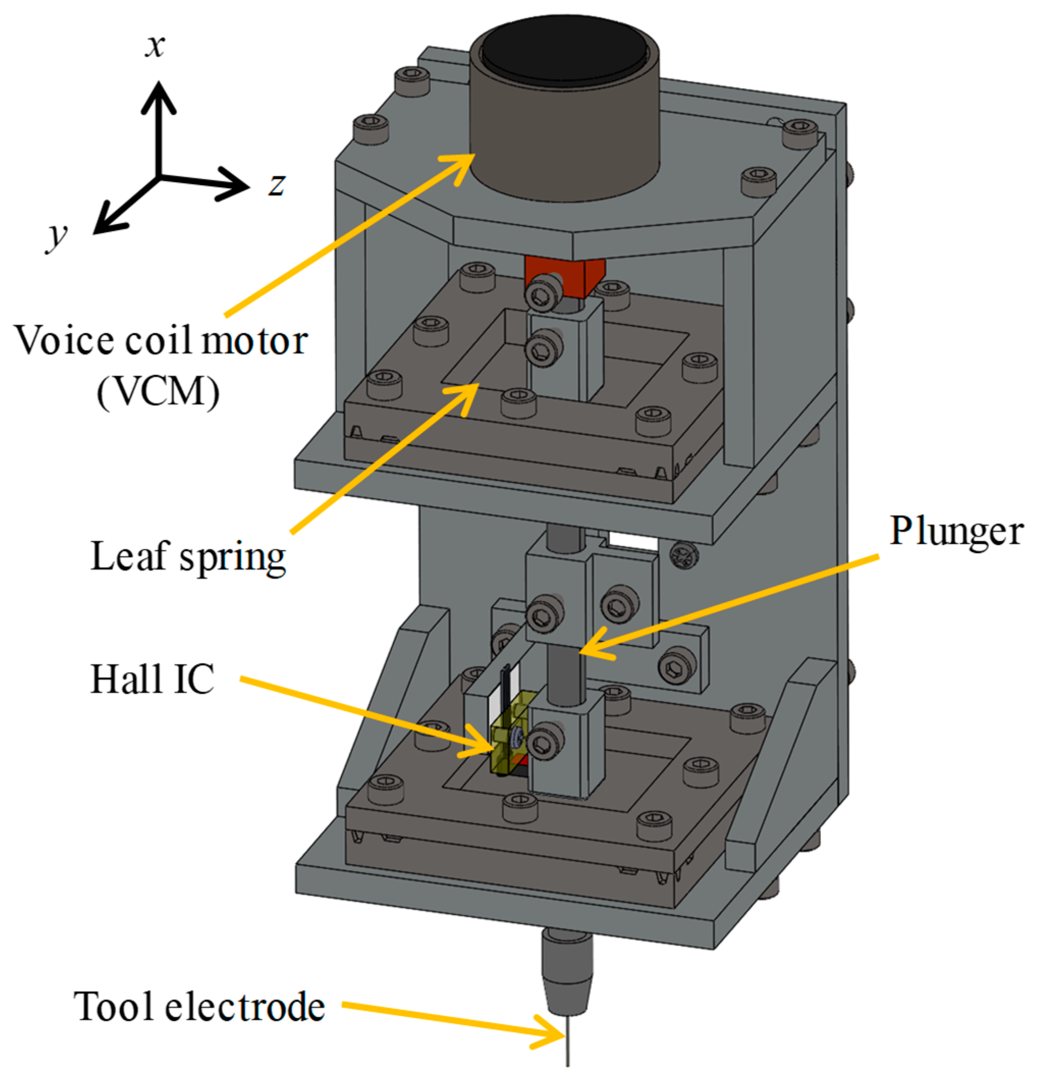
2.2. Structure of Force-Controlled Tool Electrode Holder

In ECDM, the control of the thrust force applied to the tool electrode is critically important. Excessive thrust force causes breakage of the thin workpiece, which is a brittle material. The previous holder using solenoids and coil springs had some problems, such as insufficient rigidity in the feeding directions along the y- and z-axes; and thermal expansion of the structure and current reduction of the solenoid due to generated heat [28]. To solve these problems, some parts of the self-made force-controlled tool electrode holder were improved. Figure 3 illustrates its structure [42]. The overall dimensions of the holder are a width of 70 mm, a depth of 65 mm, and a height of 137 mm. The plunger, which holds the tool electrode and is movable, has a length of 130 mm, a diameter of 6 mm, and an approximate total mass of 30 g. The VCM (MM30C06 by Shindengen Mechatronics, Kawasaki, Japan, 7.5 N/A) drives the plunger, and its shift in the holder is measured using a Hall IC (A1324LUA-T by Allegro Microsystems, Manchester, NH, USA).
For the x-direction, a lower spring constant is desirable to enable fine shift of the plunger with the VCM. In contrast, a higher spring constant is preferable for supporting the plunger in the y- and z-directions to keep verticality even when lateral forces are applied. Compared to coil springs, leaf springs generally have higher stiffness in the x-direction, making a long-stroke shift more difficult. However, their higher stiffness in the lateral directions compared to the x-direction is expected to produce a more stable posture for the tool electrode, and the designed stroke of the plunger is short. In addition, supporting the plunger at top and bottom withstands the moments generated by the friction force due to the tool electrode’s motion in the lateral directions. Therefore, the structure with two leaf springs was adopted for the support of the plunger.
Figure 4 illustrates the structure of the leaf spring. The metal foil used for the leaf spring is made of JIS-SUS304 (equivalent to AISI 304) stainless steel, with a thickness of 0.01 mm. It was clamped between frames with the outer bumps (1), and tension was evenly applied with the inner bumps (2) from four directions to eliminate sagging. Finally, fixing the foil with screws on all four sides ensures stable, constant tension over a long time. Two of the leaf springs were attached at the top and bottom of the plunger, spaced 68 mm apart. Table 2 shows the comparison of the rigidity for each axis of the holder between the previous coil spring and the proposed leaf spring. The spring constant of the leaf spring shown in Table 2 is twice that of the single leaf spring measured. The spring constants of the leaf springs both in the longitudinal and lateral directions are larger than those of the coil springs, especially in the lateral direction. Although a smaller spring constant is preferable for the longitudinal direction, the spring constant of the leaf springs is within an allowable range. The large spring constant of the leaf springs in the y-direction endures the friction due to the rotation of the workpiece.
The measured spring constants in the lateral directions were larger than that in the longitudinal direction (x-axis), and the calculated bending stiffness of the tungsten electrode with a diameter of 0.3 mm and a length of 5 mm was 29.8 N/mm. Therefore, the set of leaf springs has enough stiffness for holding the tool electrode. This keeps the posture of the plunger stable against the forces in the lateral directions during the lathe-type ECDM.
The VCM with low heat generation and high thrust force linearity was used as an actuator. Because the magnetic circuit of the VCM is closed within itself, the leakage flux seldom disturbs the Hall IC used for the measurement of the plunger shift. The VCM was driven with a self-made Class B push-pull current amplifier with a maximum output current of 50 mA and a cutoff frequency of 1 kHz. The current-drive minimizes the variation of the coil resistance due to Joule heating. The Class B amplifier with complementary transistors which reduce switching distortion provides good linearity for the thrust force generated with the VCM.
The plunger shift was measured with the Hall IC combined with a samarium-cobalt (SmCo) magnet (4 mm × 4 mm × 2 mm, 230 mT) [42]. The SmCo magnet allows less thermal demagnetization compared to a neodymium magnet and reduces thermal drift. The output of the Hall IC was amplified by a factor of 10 and through a low-pass filter with a cutoff frequency of 1 kHz. The sensitivity for the shift was 6.11 μm/V. In order to compensate for thermal drift during machining (0.84 μm/K), a temperature sensor (LM35DZ by Texas Instruments, Dallas, TX, USA) was installed near the Hall IC. An algorithm for an in-process temperature compensation was implemented.

2.3. Feeding Mechanism and Workpiece Rotation Mechanism

In order to feed the tool electrode holder, the XZ stage driven by a stepping motor (1 μm/pulse) was used. The pulses for driving the stepping motor were generated by a function generator (DF1906 by NF Corporation, Yokohama, Japan). While a gate signal through the digital output of the DSP was sent to the function generator, pulses were given to the motor driver only during each driving period. This allows for high-speed feeding of the tool electrode holder according to a designed shape.
The cutting depth of the tool electrode and on/off of the DC power supply for ECDM synchronized with the rotational angle of the workpiece. A stepping motor with a reduction ratio of 3.6 was used to rotate the workpiece and its driving pulse was generated with the DSP. The number of pulses per revolution was 7200. The workpiece was rotated through an Oldham coupling and belt transmission.
Figure 5 shows the frequency response of the plunger shift measured from the output of the Hall IC [42]. A constant current amplitude corresponding to a 10 µm peak-to-peak shift at 1 Hz was supplied to determine the system gain. The response across a frequency range showed a second-order system with a resonance frequency of 73 Hz, as shown in Figure 5a, and the steep change of the phase lag at the resonance frequency, as shown in Figure 5b. With an increase in the reference amplitude, the gain decreased further at higher frequencies. The quality factor was 19 due to the absence of damping.
With a variation of the plunger shift, the force generated by the leaf springs changes. Figure 6 shows the relationship between the VCM current and the thrust force determined experimentally [42]. A digital force gauge (ZTA-5N by Imada, Toyohashi, Japan, measurement range of 5 N, maximum sampling rate of 2 kHz) was used to measure the thrust force. For a positive VCM current, the plunger is pulled upward against the gravity so that the thrust force decreases. The shift of the tool electrode was denoted as x (μm), the thrust force as f (N), and the VCM current as im (mA). The relationship between these values was approximated as a polynomial shown in Equation (1) by the least squares method [42]:
i m = 0.00838 125 f + 8.50 f 2 + 1.65 x 0.0492 x f + 0.204 x f 2 0.00150 x 2 + 0.00495 x 2 f 0.0240 x 2 f 2 .
Figure 7 shows an example of the thrust force control [42]. The tool electrode holder was moved downward with the XZ stage, and the tool electrode contacted with the force gauge. The reference thrust force was set at 0.05 N, which is set during ECDM. Then, the thrust force was controlled. The 5% settling time for a reference thrust force of 0.05 N was 90 ms for the shift and 125 ms for the thrust force. The fluctuation in the thrust force in 50 s was 2%. The collision of the plunger with the force gauge probe caused the initial overshoot of the thrust force since those of the displacement and current were not as large.

2.4. Electrode Feeding and Power Supply Switching for Non-Circular Cross-Section ECDM

Non-circular cross-section ECDM requires selective removal based on the rotation angle of the workpiece. Two approaches are possible for the selective removal: varying the distance between the tool electrode and the workpiece; or switching the DC power supply on/off. In hole ECDM, a workpiece surface was sometimes removed even at a distance of approximately 150 μm at an applied voltage of 45 V [50]. Therefore, it was decided to implement the on/off control of the DC power supply rather than to retract the tool electrode.
Figure 8 illustrates the motion of the tool electrode from the initial position alignment of the plunger to the beginning of ECDM [42].
  • At the beginning of the sequence, the Hall IC output is acquired at the equilibrium position of the plunger shown in Figure 8a. This is set as the origin for measuring the plunger shift, and the shift is calculated as the change in the Hall IC output.
  • The stage is moved downward to contact the tool electrode with the workpiece.
  • As shown in Figure 8b, the stage is moved slightly downward to apply a thrust force against the workpiece due to the weight of the tool electrode and the deflection of the leaf springs. The total displacement and shift are set as the start positions of ECDM.
  • The tool electrode is driven with the VCM within ±5 μm of the shift at Step 3 during ECDM. When the shift exceeds ±5 μm, it is compensated for by moving the tool electrode holder with the XZ stage. The VCM moves faster than the stage; their motions do not conflict.
In the actual ECDM process, the following cycle is repeated: the removal by on/off control of the DC power supply during two revolutions of the workpiece, and the shape measurement during one subsequent revolution. In order to prevent the tool electrode from bending when the posture of the tool electrode deviates from the normal direction of the workpiece surface, or when it snags on the surface bumps, the spindle is stopped and a jump motion height of 0.5 mm is added with the XZ stage every 7° of the spindle rotation. Since it is not a multiple of 360°, the jump angle was dispersed. A detailed machining sequence is described in Section 4.1.
As shown in Figure 9, the workpiece is modeled as a combination of triangles with 1°-apexes. During each measurement step, the difference between the designed and actual area is calculated as a residual area for each triangle. The actual surface is approximated by the bases of the triangles. The sum of these differences is defined as the remaining area, and the sum of the apexes of the residual areas is defined as the residual angle. The angles are measured relative to the rotation center. Since the residual area and angle are automatically detected by repeating the on-machine measurement and machining cycle, no manual operation is necessary during non-circular machining, even for a long time process. When the tool electrode contacts within the residual angle, the DC power supply turns on to remove material there. When the tool electrode reaches a completely removed area, the power supply turns off.

3. On-Machine Measurement of Shape

This system measures a contour of a workpiece by combining the stage displacement with the shift of the tool electrode working as a contact probe. The tool electrode with a flat tip and a diameter of 0.3 mm is pressed against the workpiece with a constant thrust force of 0.05 N. The workpiece is rotated at 30 min−1. For each pulse to rotate the spindle, the stage displacement and the tool electrode shift are acquired, and the total displacement is calculated as the position of the tool electrode. Data from 7200 pulses per revolution are averaged every 20 points to form the contour per degree. Since the surface of the unmachined glass rod is smooth, the tool electrode did not sag.
In order to verify the performance of this system, a soda-lime glass rod with a diameter of 5 mm was measured with the tool electrode holder and a lever-type electronic micrometer (MLH-322 by Mitutoyo, Kawasaki, Japan, range: ±0.5 mm, thrust force: 0.02 N, linearity: ±0.5%, probe diameter: 2 mm) immediately adjacent to the tool electrode. The electronic micrometer acquired 10,000 points per revolution, and an average of 27 points was taken to represent the data per degree.
Figure 10 shows a measurement example of the glass rod. The results were displayed with an offset of 100 µm for the comparison. The workpiece was rotated clockwise, starting from the right side of Figure 10. The measured roundness was 177 µm for the tool electrode holder and 176 µm for the electronic micrometer. By comparing the measured radii of each point, the maximum absolute difference between them was 11 µm, with a standard deviation of 4 µm. The average diameter measured at 10 points with the micrometer was 5.108 mm, with a maximum-minimum difference of 127 µm. The average coincided with the result of the on-machine measurement.

4. Non-Circular Cross-Section Grooving

4.1. Control and ECDM Conditions for Non-Circular Section

Figure 11 shows the machining sequence of ECDM. The removal process follows the setting of the initial position shown in Figure 8 and the initial shape measurement.
  • At the beginning of the machining sequence, the initial position in the x-direction is set by the sequence shown in Figure 8.
  • The initial contour is measured by the process described in Section 3 at some positions to calculate the alignment errors, such as the eccentricity and inclination of the workpiece.
  • The initial residual areas are roughly calculated, and the residual angle is set to 360, as shown in Figure 9.
  • The tip of the tool electrode is fed to the starting point of ECDM by manually moving the stage in the x- and z-directions. Then, ECDM begins.
  • The contour is measured every 1 degree during one revolution of the workpiece.
  • The residual areas every 1° and residual angle are calculated based on the contour measured in Step (5).
  • The machining sequence is continued until the residual angle is not zero.
  • ECDM is carried out during two revolutions of the workpiece. The DC voltage turns on at the angle where the residual area is not zero, and off at the angle where the residual area has reached once to zero. The tool electrode is retracted upward as a jump motion every 7° during this step.
  • Return to Step (5).
Table 3 shows the experimental conditions. A square cross-section with sides of 3 mm was grooved from a glass rod with a diameter of 5 mm, which is another one described in Section 3. For deep hole ECDM, the tool electrode shape such as a drill or pipe hastens debris evacuation, as mentioned in Section 1. In lathe-type ECDM, since only the surface is removed and the workpiece rotation circulates the electrolyte, a solid, simple cylindrical tool electrode is sufficient.
This time, the groove was machined using only feed in the x-direction, with no feed in the z-direction. The initial measurements before machining and the actual machining operation mode were switched manually. Everything else proceeded automatically. The jump motion and measurement cycle resulted in a net removal time of approximately 22% (110 min) of the total machining time (530 min).
The rotation speed was set to 3 min−1 by considering the tracking speed of the XZ stage. A 15 wt% NaCl solution was used as the electrolyte, and the applied voltage was set to 50 V for the discharge stability. The sodium ions in the NaCl solution react chemically with silicon oxide, and convert to sodium silicate, a reaction that is accelerated by the discharge heat. Then, the sodium silicate dissolves into the solution as mentioned in Section 1.

4.2. Measurement of Machined Result

Figure 12 shows a photo of the cross-section of the machined part designed as a square. Hereafter, the upper, right, lower, and left sides are denoted as the north, east, south, and west ones, respectively. The machined shape at the upper right corner appears distorted due to the observation from the fractured surface. All sides bulged at the center. The dimensions measured with an optical microscope were 3.23 mm and 3.32 mm at the center, and 2.99 mm and 2.94 mm at the edges.
Figure 13 shows the side and top view of the groove. A ridge was observed at the center of the groove bottom. In hole ECDM, such convex shape occurs because electrolyte is not supplied directly beneath the tool electrode tip [51]. Similarly, increased rigidity of the electrode holder in the lateral directions caused the electrode to maintain vertical contact, so that the electrolyte was hardly supplied beneath the tool electrode tip.
The groove width was 490 μm. The straightness of the groove edges at the lateral surface of the glass was comparable to that of the machined surface roughness. The slow rotational speed and long machining time caused bubbles to be trapped between the lateral surface of the tool electrode and the machined side wall, and the side wall was excessively removed in the lateral direction.
Figure 14 shows the progress of ECDM. The cross-sectional areas of the workpiece and designed shape are 21.5 mm2 and 9.0 mm2, respectively. The difference between them, of 12.5 mm2, is the initial residual area. The initial residual angle is 360 degrees. The entire circumference was removed up to approximately 80 cycles, when the radius reached 2.12 mm. Then, machining gradually ended from the area closer to the corners. Consequently, the residual angle also decreased accordingly. In the early process, the residual angle and area decreased linearly in proportion to the machining time. However, once the corners began to form, the decrease rate in the residual angle accelerated. The posture of the tool electrode inclining far from the normal direction of the contact point affected the measured shape. Even with a small residual area, it was detected as a residual angle. Therefore, the residual angle significantly fluctuated after 130 cycles where the arc shape decreased.
Figure 15 shows the results of the on-machine measurement of the machined area of the glass rod before and after ECDM. At positions −5, −10, and −15 mm from the machining position, the average deviation was 0.10 mm. This is due to the wear length of the tool electrode.

4.3. Shape Errors

In ECM using electrolyte jets, errors concerning slopes have been evaluated. The gravity and the angle between the jet and the surface affected the error [52]. ECDM is mainly used to machine holes and grooves, and errors have been evaluated focusing specifically on hole entrance diameter. In ECDM, the extent of bubbles and their flow direction affect the errors, since discharges occur within bubbles [23,25]. In this section, the error is discussed by extending the ECM cases as well as the hole and groove ECDM.
After ECDM, the shape was measured on the ECD machine and also with the electronic micrometer. In order to measure the bottom of the narrow groove, a twist drill with a diameter of 0.3 mm was used as a contact probe. The workpiece was rotated on a rotary stage, and the entire circumference was measured at every 10° interval.
Figure 16 shows the measurement results. The shapes were approximated as squares and shown with their centers aligned. The dots represent measurements with the electronic micrometer, the solid lines indicate the on-machine measurement, and the dashed lines indicate the shape with the offset outward by the wear length of tool electrode. A small scratch was made on the tool electrode near the end of pin vise, and the wear length was measured using an optical microscope with that point as the reference. The measured length was 0.07 mm. The shape measured with the electronic micrometer nearly coincided with that corrected for the tool electrode wear. Therefore, the shape error was evaluated using the data, in which the offset was corrected, with a higher number of measurement points.
In stainless steel electrodes, wear primarily results from the discharge heat [25]. Since copper electrodes are soft, friction on the workpiece becomes another cause of the wear in addition to thermal effects [53]. This study employs tungsten electrodes, which are tough on the heat and friction. In ECDM, a pulsed discharge current flows, causing an electric double layer to form on the surface of the tool electrode, followed by a reverse current flow. This causes the tool electrode wear by electrolysis [54,55,56]. In the NaCl electrolyte, there are sodium ions. Tungsten becomes sodium tungstate (Na2WO4) during ECDM, which is denoted as
W O 3 + 2 N a O H N a 2 W O 4 + H 2 O .
Then, it is dissolved into the solution [57], especially in alkaline solutions [58]. The machined shape becomes larger due to the tool electrode wear, which causes the offset.
Table 4 shows the dimensional errors. The centers of each side bulged beyond the designed shape. The side length of the approximated square within ±1 mm from the center was 3.15 mm, which was larger than the designed length of 3 mm. The angles between adjacent edges ranged from 88.5° to 92.2°. The straightness varied from 0.11 mm to 0.15 mm, perpendicularity from 0.14 mm to 0.27 mm, and parallelism from 0.12 mm to 0.16 mm. The linearity near the corners deteriorated significantly due to the excessive removal beyond the designed shape. The discharge from the side surface of the tool electrode mainly caused this shape error. Figure 17 illustrates a schematic view of the relative position between the machined surface and the tool electrode. When the electrode contacts the workpiece surface from the normal direction at the middle section, as shown in Figure 17a, the surface is removed equally from both sides of the tool electrode. Since the reference point of the machine is located within the tool electrode holder, it is impossible to distinguish between the electrode wear and workpiece removal. Consequently, the machining depth is reduced equal to the length of the tool electrode wear. In the case of machining corners, as shown in Figure 17b, not only the tip but also the side surfaces of the tool electrode come into close proximity with the machined surface. In this experiment, the side of the tool electrode was not insulated, and the discharge from the side surface therefore also significantly contributed to the removal. Then, the areas near the corners were excessively removed. The control program was designed under the assumption that the workpiece surface is removed only at the tip of the tool electrode, and the voltage is not applied at angles where the designed machining amount is reached. However, the workpiece surface is actually removed even in areas distant from the tip of the tool electrode [50], which caused this error.
As shown in Figure 14, the middle area remains unmachined until the end. Since the machining reference point is located on the tool electrode holder side, the machined dimensions increase as the tool electrode wears down. Consequently, the middle area experiences greater residual machining and larger errors compared to the corners.
Figure 18 shows the results of measuring the machined shape just after machining and after leaving it for one hour. The measured shape was below the designed one just after machining. However, it became larger and exceeded the designed one over time. This occurred because the tool electrode moved downward due to thermal expansion of the XZ stage caused by heat generated by the stepper motor, and the machine origin drifted during machining. By installing many sensors at various positions on the device, thermal deformation can be estimated and compensated for by the feedback to the actuators. However, this results in a highly complex overall system [59,60]. In this paper, since a demonstration of the non-circular machining is the primary objective, only the plunger shift was compensated for the thermal deformation within the tool electrode holder by the software, as mentioned earlier.

5. Conclusions

This paper describes the demonstration of machining a non-circular cross-sectional shape using a lathe-type ECD machine. To press the tool electrode against the workpiece with a small trust force, the tool electrode was driven by the VCM and supported by the leaf springs to ensure straight feed. This enabled the precise longitudinal feed of the tool electrode. The following conclusions can be drawn.
  • By comparing the designed shape with the measured one and controlling the machining voltage on/off, a square cross-section was successfully machined. By repeating the removal and measurement processes alternately, the machining accuracy was improved. Although the thermal effect on the measurement of the shift of the tool electrode was compensated for by the temperature sensor, the thermal deformation of the stage also affected the shape errors.
  • In the case of machining near a corner, the machined surface is inclined, and one side of the tool electrode approaches there. The surface was unexpectedly removed due to discharges generated at points other than the tool electrode tip. The restriction of the machining range was difficult because the side surface of the tool electrode was not insulated. This caused the machining error at the corners.
  • The on-machine measurement of the contour was measured by combining the tool electrode shift measured with the Hall IC embedded in the tool electrode holder with the XZ stage displacement that moves the holder. The measurement accuracy was in the order of micrometers. This is sufficient for improving the machining accuracy through the alternating process of the measurement and ECDM.
For future studies, the errors will be quantitatively estimated, and peripheral turning will be carried out by feeding the tool electrode in the longitudinal direction.

Author Contributions

Conceptualization, K.F.; methodology, K.F.; software written by T.I.; validation, K.F. and T.I.; formal analysis, K.F. and T.I.; investigation, T.I.; resources, K.F.; data curation, K.F. and T.I.; writing—original draft preparation, K.F.; writing—review and editing, T.I.; visualization, K.F. and T.I.; supervision, K.F.; project administration, K.F.; funding acquisition, K.F. All authors have read and agreed to the published version of the manuscript.

Funding

This study was financially supported in part by JSPS KAKENHI, Grant Number JP18K03885.

Data Availability Statement

The original contributions presented in this study are included in the article. Further inquiries can be directed to the corresponding author.

Conflicts of Interest

The authors declare no conflicts of interest.

Abbreviations

The following abbreviations are used in this manuscript:
ECDMElectrochemical Discharge Machining
ECMElectrochemical Machining
EDMElectrical Discharge Machining
VCMVoice Coil Motor
DSPDigital Signal Processor

References

  1. Fytory, M.; Giannetti, A.; Baldini, F.; Berneschi, S.; Marcucci, N.; Trono, C.; Tombelli, S. Glass-based microfluidics in biosensing and bioassays: From fabrication techniques to application to bacteria detection. Opt. Mater. 2025, 167, 117350. [Google Scholar] [CrossRef]
  2. Hamed, H.; Eldiasty, M.; Seyedi-Sahebari, S.M.; Abou-Ziki, J.D. Applications, materials, and fabrication of micro glass parts and devices: An overview. Mater. Today 2023, 66, 194–220. [Google Scholar] [CrossRef]
  3. Sugioka, K.; Cheng, Y. Femtosecond laser three-dimensional micro- and nanofabrication. Appl. Phys. Rev. 2014, 1, 041303. [Google Scholar] [CrossRef]
  4. Mehta, K.M.; Kumar, P.S.; Shaikh, V.A. Unconventional Machining of ceramic matrix Composites—A review. Mater. Today Proc. 2021, 46, 7661–7669. [Google Scholar] [CrossRef]
  5. Račiukaitis, G. Ultra-Short Pulse Lasers for Microfabrication: A Review. IEEE J. Sel. Top. Quantum Electron. 2021, 27, 1100112. [Google Scholar] [CrossRef]
  6. Ghasemian Fard, M.; Nag, A.; Petrů, J.; Hloch, S. Towards sustainable precision: A review of water jet meso and micromachining. Results Eng. 2025, 27, 106447. [Google Scholar] [CrossRef]
  7. Kanda, T.; Makino, T.; Ono, T.; Suzumori, K.; Morita, T.; Kurosawa, M.K. A micro ultrasonic motor using a micro-machined cylindrical bulk PZT transducer. Sens. Actuators A Phys. 2006, 127, 131–138. [Google Scholar] [CrossRef]
  8. Dadkhahipour, K.; Nguyen, T.; Wang, J. Mechanisms of channel formation on glasses by abrasive waterjet milling. Wear 2012, 292–293, 1–10. [Google Scholar] [CrossRef]
  9. Liu, K.; Nickolov, Z.; Oh, J.; Noh, H. KrF excimer laser micromachining of MEMS materials: Characterization and applications. J. Micromech. Microeng. 2012, 22, 015012. [Google Scholar] [CrossRef]
  10. Xu, X.; Lin, B.; Chen, H.; Lv, B.; Li, J.; Zhao, P.; Zhou, J.; Jia, J.; Sui, T.; Lin, J. Obstacles and bottleneck breakthroughs affecting the development of hydroxyl radicals assisted chemical mechanical polishing. J. Environ. Chem. Eng. 2025, 13, 119567. [Google Scholar] [CrossRef]
  11. Song, Y.; Chi, F.C.; Fang, F.; Han, H.; Wang, C. Multi-physical field coupling polishing of diamond for atomic-scale damage-free surface. Int. J. Extrem. Manuf. 2026, 8, 032004. [Google Scholar]
  12. Paul, L.; Hiremath, S.S. Experimental and Theoretical Investigations in ECDM Process -An Overview. Procedia Technol. 2016, 25, 1242–1249. [Google Scholar] [CrossRef]
  13. Oza, A.D.; Goyal, A.; Buch, V.; Kumar, M. Electrochemical discharge machining process: A review on process parameters and future scope. Mater. Today Proc. 2022, 62, 6956–6961. [Google Scholar] [CrossRef]
  14. Wang, C.; Sasaki, T.; Hirao, A. Micro shaft turning by electrochemical discharge machining using a sandwich cathode. Precis. Eng. 2025, 94, 344–357. [Google Scholar] [CrossRef]
  15. Sharma, S.K.; Milojević, S.; Sharma, L.K.; Gajević, S.; Sharma, Y.; Sharma, M.; Čukić, S.; Stojanović, B. Friction Stir Processing: An Eco-Efficient Route to High-Performance Surface Architectures in MMCs. Processes 2026, 14, 306. [Google Scholar] [CrossRef]
  16. Paliwal, S.; Sudhakar, R.P.; Mittal, K.K. Study of electrochemical discharge machining of glass. Mater. Today Proc. 2021, 37, 1828–1833. [Google Scholar] [CrossRef]
  17. Chen, X.; Zhang, A.; Ma, T.; Zhu, Q.; Zhou, J.; Wang, B.; Ma, N.; Liu, H.; Chen, Y. Mechanism of electrochemical discharge machining on film cooling holes with thermal barrier coatings. Int. J. Adv. Manuf. Technol. 2025, 137, 717–729. [Google Scholar] [CrossRef]
  18. Abou Ziki, J.D.; Wüthrich, R. Effect of Machining Limiting Factors on Drilling Progress during Spark Assisted Chemical Engraving (SACE): General Trends. Ceramics 2021, 4, 618–627. [Google Scholar] [CrossRef]
  19. Liu, Y.; Wei, Z.; Wang, M.; Zhang, J. Experimental investigation of micro wire electrochemical discharge machining by using a rotating helical tool. J. Manuf. Process. 2017, 29, 265–271. [Google Scholar] [CrossRef]
  20. Ranganayakulu, J.; Srihari, P.V.; Rao, K.V. A strategy to improve performance in electrochemical discharge machining using periodic bi-directional tool rotation. Int. J. Adv. Manuf. Technol. 2022, 123, 1459–1476. [Google Scholar] [CrossRef]
  21. Ma, N.; Long, F.; Chen, Y.; Sun, J. Mechanistic insights and process optimization for micro-hole machining in SiC/SiC composites via electrochemical discharge: Towards surface integrity control. Compos. Part A Appl. Sci. Manuf. 2026, 200, 109380. [Google Scholar] [CrossRef]
  22. Tong, H.; Luo, Y.; Liu, G.; Li, Y.; Nawaz, S.A. A hybrid process of electrochemical discharge machining (ECDM) and high-speed milling (HSM) on quartz glass. Int. J. Adv. Manuf. Technol. 2025, 139, 535–547. [Google Scholar] [CrossRef]
  23. Tiwari, A.K.; Panda, S.S. Effect of disk-shaped tools on ECDM performance in micro-hole drilling. Precis. Eng. 2025, 94, 218–235. [Google Scholar] [CrossRef]
  24. Arya, R.K.; Dvivedi, A. Improving the electrochemical discharge machining (ECDM) process for deep-micro-hole drilling on glass by application of the electrolyte-air injection. Ceram. Int. 2023, 49, 8916–8935. [Google Scholar] [CrossRef]
  25. Shanu, A.; Dixit, P. Investigation of Debris Removal Mechanism in Ultrasonic-Assisted Electrochemical Discharge Machining. J. Electrochem. Soc. 2025, 172, 063505. [Google Scholar] [CrossRef]
  26. Grover, S.; Mangal, S.K.; Singh, S.; Singh, M.; Rajput, V.; Sharma, S.; Kumar, A.; Abbas, M. Experimental investigation of micro-machining of borosilicate glass using an ultrasonic assisted rotary electrochemical discharge machining (UA-RECDM) process. J. Micromech. Microeng. 2024, 34, 055003. [Google Scholar] [CrossRef]
  27. Wang, C.; Liu, Y.; Wang, T.; Xu, H.; Wang, K. A green and precision compound machining method for glass micro components—Ultrasonic assisted electrochemical discharge grinding with multi-hole tube electrode. CIRP J. Manuf. Sci. Technol. 2024, 52, 129–148. [Google Scholar] [CrossRef]
  28. Furutani, K.; Harada, K.; Tsuchiya, T. Electrochemical Discharge Machining under Thrust Force Control in Lathe-type Machine. Int. J. Electr. Mach. 2024, 29, 1–7. [Google Scholar] [CrossRef]
  29. Han, W.; Kunieda, M. Precision electrochemical machining of tungsten micro-rods using wire electrochemical turning method. Int. J. Adv. Manuf. Technol. 2020, 111, 295–307. [Google Scholar] [CrossRef]
  30. Kurafuji, H.; Suda, K. Electrical Discharge Drilling of Glass. Ann. CIRP 1968, 16, 415–419. [Google Scholar]
  31. Saranya, S.; Ravi Sankar, A. Fabrication of precise micro-holes on quartz substrates with improved aspect ratio using a constant velocity-feed drilling technique of an ECDM process. J. Micromech. Microeng. 2018, 28, 125009. [Google Scholar] [CrossRef]
  32. Nawaz, S.A.; Cao, P.; Tong, H.; Li, Y. Micro ECDM process comparison using different tool feed methods of constant gravity and spring-force. J. Phys. Conf. Ser. 2024, 2671, 012001. [Google Scholar] [CrossRef]
  33. Chak, S.K.; Venkateswara Rao, P. Trepanning of by electro-chemical discharge machining (ECDM) process using abrasive electrode with pulsed DC supply. Int. J. Mach. Tool. Manuf. 2007, 47, 2061–2070. [Google Scholar] [CrossRef]
  34. Ji, B.; Tong, H.; Han, X.; Li, Y.; Pu, Y. Energy action model of spark assisted chemical engraving (SACE) for improving surface quality of micro cavities in ZrO2 ceramics. J. Micromech. Microeng. 2020, 30, 085011. [Google Scholar] [CrossRef]
  35. Nawaz, S.A.; Cao, P.; Tong, H.; Li, Y. Micro ECDM scanning process with feedback control of flexible contact force. J. Manuf. Process. 2023, 94, 266–277. [Google Scholar] [CrossRef]
  36. Arya, R.K.; Appalanaidu, B.; Dvivedi, A. Parametric investigation on an adaptive tool feeding system for ECDM. Int. J. Interact. Des. Manuf. 2024, 18, 7011–7020. [Google Scholar] [CrossRef]
  37. Hirooka, D.; Furushiro, N.; Yamaguchi, T. Three-dimensional indentation test system for observing the distribution of internal mechanical properties in materials. Precis. Eng. 2024, 91, 143–154. [Google Scholar] [CrossRef]
  38. Liu, Y.T. Recent Development of Piezoelectric Fast Tool Servo (FTS) for Precision Machining. Int. J. Precis. Eng. Manuf. 2024, 25, 851–874. [Google Scholar] [CrossRef]
  39. Wang, J.; Yao, D.; Wang, R.; Gao, Z.; Liu, M.; Ye, X.; Li, X. An integrated push-to-pull micromechanical device: Design, fabrication, and in-situ experiment. Extrem. Mech. Lett. 2024, 72, 102228. [Google Scholar] [CrossRef]
  40. Gudlavalleti, S.; Gearing, B.P. Flexure-based Micromechanical Testing Machines. Exp. Mech. 2005, 45, 412–419. [Google Scholar] [CrossRef]
  41. Mizuno, T.; Hayashi, Y.; Takasaki, M.; Ishino, Y.; Yamaguchi, D. Development of Three-degree-of-freedom Zero-compliance Mechanism for Micro Force Measurement with a Cantilever. IFAC-PapersOnLine 2020, 53, 8339–8344. [Google Scholar] [CrossRef]
  42. Furutani, K.; Irie, T. Prototype of Force-Controlled Tool Electrode Holder for Lathe-Type Electrochemical Discharge Machine. In Proceedings of the 7th Jc-IFToMM International Symposium, Kitakyushu, Japan, 22–23 June 2024; pp. 118–123. [Google Scholar]
  43. Higuchi, T.; Yamaguchi, T. Study of non-circular machining. (1st report). The application of inverse transfer function compensation. J. Jpn. Soc. Precis. Eng. 1988, 54, 145–150. [Google Scholar] [CrossRef]
  44. Higuchi, T.; Yamaguchi, T. Development of a High Speed Non-circular Machining NC-lathe for Cutting a Piston by the Use of a New Positioning Servomechanism by Electromagnetic Force. In Proceedings of the 1990 Japan-U.S.A. Symposium on Flexible Automation, Kyoto, Japan, 9–13 July 1990; pp. 715–720. [Google Scholar]
  45. Yang, J.; Ai, W.; Liu, Y.; Chen, B. Kinematics model and trajectory interpolation algorithm for CNC turning of non-circular profiles. Precis. Eng. 2018, 54, 212–221. [Google Scholar] [CrossRef]
  46. Cao, R.; Hou, Z.; Zhao, Y.; Zhang, B. Model Free Adaptive Iterative Learning Control for Tool Feed System in Noncircular Turning. IEEE Access 2019, 7, 113712–113725. [Google Scholar] [CrossRef]
  47. Takasugi, K.; Morimoto, Y.; Kaneko, Y.; Suzuki, N.; Asakawa, N. Improvement of machining accuracy for 3D surface machining with CNC lathe. J. Adv. Mech. Des. Syst. Manuf. 2018, 12, 18-00034. [Google Scholar] [CrossRef]
  48. Arndt, T.; Schulze, V. Non-Circular-Rotary-Turning process for manufacturing parts with non-circular contours. CIRP Ann.—Manuf. Technol. 2024, 73, 61–64. [Google Scholar] [CrossRef]
  49. Pelic, M.; Gapinski, B.; Ptaszynski, W. Application of Piezoelectric Fast Tool Servo for Turning Non-Circular Shapes Made of 6082 Aluminum Alloy. Appl. Sci. 2021, 11, 7533. [Google Scholar] [CrossRef]
  50. Furutani, K. Relationship between applied voltage and current waveform in electrochemical discharge machining. Trans. Jpn. Soc. Mech. Eng. 2020, 86, 20-00197. [Google Scholar] [CrossRef]
  51. Tokura, H.; Kondoh, I.; Yoshikswa, M. Ceramic material processing by electrical discharge in electrolyte. J. Mater. Sci. 1989, 24, 991–998. [Google Scholar] [CrossRef]
  52. Zhao, Y.; Kunieda, M. Investigation on electrolyte jet machining of three-dimensional freeform surfaces. Precis. Eng. 2019, 60, 42–53. [Google Scholar] [CrossRef]
  53. Nawaz, S.A.; Cao, P.; Tong, H.; Li, Y. Reducing tool-tip wear in micro-ECDM scanning process with feedback control of flexible contact force. Int. J. Adv. Manuf. Technol. 2024, 131, 3527–3538. [Google Scholar] [CrossRef]
  54. Zhan, S.; Zhao, Y. Suppression of cathode tool wear by a forward-bias voltage in pulsed spark-assisted chemical engraving. Electrochem. Commun. 2020, 111, 106643. [Google Scholar] [CrossRef]
  55. Zhu, Y.; Liu, G.; Li, Y.; Tong, H. Wear mechanism and preventive method of silicon electrodes in micro ECM. Int. J. Adv. Manuf. Technol. 2024, 131, 1137–1149. [Google Scholar] [CrossRef]
  56. Zhang, Q.; Luo, H.; Natsu, W. Parameter Identification of Equivalent Circuit for Pulsed Electrochemical Machining Based on Experimentally Obtained Current Waveforms. Int. J. Precis. Eng. Manuf. 2024, 25, 2491–2500. [Google Scholar] [CrossRef]
  57. Oishi, T.; Yaguchi, M. Solubility of Sodium Tungstate in Molten Sodium Hydroxide. Electrochemistry 2018, 86, 61–65. [Google Scholar] [CrossRef]
  58. Mishra, D.K.; Dixit, P. Experimental investigation into tool wear behaviour of line-array tool electrode during the electrochemical discharge micromilling process. J. Manuf. Process. 2021, 72, 93–104. [Google Scholar] [CrossRef]
  59. Kristiani, E.; Wang, L.Y.; Liu, J.C.; Huang, C.K.; Wei, S.J.; Yang, C.T. An Intelligent Thermal Compensation System Using Edge Computing for Machine Tools. Sensors 2024, 24, 2531. [Google Scholar] [CrossRef]
  60. Jia, G.; Zhang, X.; Shen, Y.; Huang, N. Analysis and modeling of comprehensive thermal positioning error in closed-loop multi-axis drive systems: A study on thermal drift and thermal positioning error. Int. J. Adv. Manuf. Technol. 2025, 140, 1895–1911. [Google Scholar] [CrossRef]
Figure 1. Concept of non-circular section machining with lathe-type ECD machine [42]. The light blue and orange arrows indicate the motions of the stage in the x- and z directions, respectively. The blue arrow indicates the fine motion of tool electrode by a combination of shift with VCM and stage displacement in the x-direction. The violet curved arrow indicates the workpiece rotation. The violet straight arrow indicates the motion of tool electrode on the workpiece in the y-direction by a combination of total displacement in the x-direction and rotation of the workpiece.
Machines 14 00308 g001
Figure 2. Configuration of the lathe-type ECD machine.
Machines 14 00308 g002
Figure 3. Structure of force-controlled tool electrode holder [42].
Machines 14 00308 g003
Figure 4. Structure of leaf spring. (a) Top view; (b) Sectional view. Bumps (1) and (2) hold the foil and apply tension, respectively. Unit: mm.
Machines 14 00308 g004
Figure 5. Frequency response of plunger shift. (a) amplitude, (b) phase. The blue, green and red lines indicate amplitudes of 2, 5 and 10 μmp-p [42].
Machines 14 00308 g005
Figure 6. Relationship between thrust force, plunger shift, and driving current of VCM [42].
Machines 14 00308 g006
Figure 7. Step response of plunger under thrust control [42]. The reference thrust force is 0.05 N.
Machines 14 00308 g007
Figure 8. Motion of tool electrode from initial position alignment of plunger to beginning of ECDM [42]. (a) Equilibrium position of the plunger. (b) Applying a thrust force against the workpiece.
Machines 14 00308 g008
Figure 9. Model of a workpiece represented by a combination of triangles, with definitions of the residual area and angle. The actual surface is approximated by the bases of the triangles. The DC power supply turns on when the tool electrode contacts only within the residual area.
Machines 14 00308 g009
Figure 10. Measurement example of glass rod. The maximum absolute difference of the radii between the electrical comparator and on-machine measurement was 11 µm, with a standard deviation of 4 µm for a diameter of 5.108 mm. The dotted chain line indicates an ideal circular outline.
Machines 14 00308 g010
Figure 11. Machining sequence for preparation and ECDM. The numbers correspond to the steps described in the main text.
Machines 14 00308 g011
Figure 12. Cross-section of machined part designed as a square. The images were captured using a focus stacking method. The upper right corner appears distorted due to the refraction caused by the warp of the end surface of the glass rod. The upper, right, lower, and left sides are denoted as the north (N), east (E), south (S), and west (W) ones, respectively.
Machines 14 00308 g012
Figure 13. Front and top view of groove. (a) Front view; (b) Top view. The edges of the side walls are slightly blurred because the images were captured using a focus stacking method. The indicated dimensions with the unit of mm are measured with the optical microscope.
Machines 14 00308 g013
Figure 14. Progress of ECDM.
Machines 14 00308 g014
Figure 15. Results of the on-machine measurement of some positions from the groove. Dashed and solid lines indicate before and after ECDM, respectively. The rotation center is the same.
Machines 14 00308 g015
Figure 16. Measurement results with shapes approximated as squares. Each side is labeled as N, E, S, and W clockwise from the top. Unit: mm. The cross marks and yellow lines are not used for the evaluation of the shape errors. The directions correspond to Figure 12 (N: north, E: east, S: south, W: west).
Machines 14 00308 g016
Figure 17. Schematic of relative position between machined surface and tool electrode. (a) The tool electrode contacts with the workpiece in the normal direction. (b) The tool electrode contacts with the workpiece at a significant angle.
Machines 14 00308 g017
Figure 18. Measurement results of machined shape just after machining and after leaving it for one hour. The rotation center is the same, except before machining.
Machines 14 00308 g018
Table 1. Specifications of self-made ECD machine.
Dimensions of entire machineW 370 mm × D 260 mm × H (approximately) 225 mm
Dimensions of force-controlled tool electrode holderEntire: W 70 mm × D 65 mm × H 137 mm
plunger: L 130 mm × D 6 mm, 30 g
XZ stageALD-6012-G0M by Chuo Precision Industrial, Tokyo, Japan, stroke: ±12.5 mm, resolution: 0.001 mm
Voice coil motorMM30C06 by Shindengen Mechatronics,
Hanno, Japan,
voltage: 6 V, resistance: 23 Ω, rated thrust: 7.5 N/A
Spindle motorPK543AW-T3.6 by Oriental Motor, Tokyo, Japan,
5-phase stepping motor, reduction ratio: 3.6
Digital signal processorsBOX by MIS, Tokyo, Japan, TMS320C6713, 225 MHz
AD 16 bit 6 ch 250 kHz, DA 12 bit 8 ch 2 μs/V,
digital I/O 8 ch + 8 ch
DC power supplyEX-750H2 by Takasago, Kawasaki, Japan,
240 V, 12.5 A, 750 W
Temperature sensor ICLM35DZ by Texas Instruments, Dallas, TX, USA,
10 mV/deg.
Hall ICA1324LUA-T by Allegro Microsystems,
Manchester, NH, USA,
sensitivity: 5000 mV/0.1 mT
MagnetSamarium-cobalt (SmCo),
4 mm × 4 mm × 2 mm, 230 mT
Working tankW 370 mm × D 260 mm × H 120 mm
Tubing pumpTP-20SA by As One, Osaka, Japan, 5–1000 mL/min
Table 2. Comparison of Rigidity for Tool Electrode Holders. The spring constant of the leaf springs is twice that of the single leaf spring.
DirectionsCoil Springs [28]Leaf Springs
Spring Constant N/mmRatio to x-DirectionSpring Constant N/mmRatio to x-DirectionRatio to Coil Springs
x2.51.09.21.03.7
y1.40.686.09.361.4
z2.10.858.66.427.9
Table 3. ECDM Conditions.
Tool Electrode (cathode)Solid cylindrical tungsten rod ϕ0.3 mm,
approximate length 5 mm
Initial immersion depth of tool electrode2–3 mm
Anode electrodeGraphite ϕ20 mm,
approximate immersion depth 20 mm
WorkpieceSoda-lime glass ϕ5 mm,
measured average diameter 5.235 mm
Electrolyte15 wt% NaCl solution
Applied voltage for ECDM50 V
Rotation speed of workpiece3 min−1
Reference thrust force0.05 N
Stage speed (x-direction)1.2 mm/s
Jump motion of tool electrode
(x-direction)
Every 7°, height 0.5 mm, speed 1.2 mm/s
Total machining time530 min
Net removal timeApproximately 110 min
Table 4. Dimensional errors. The directions correspond to Figure 12 (N: north, E: east, S: south, W: west, NS: between north and south, EW: between east and west, NE: between north and east, ES: between east and south, SW: between south and west, WN: between west and north). Each value and the corner positions estimated were calculated from Figure 16.
Straightness µmN: 153, E: 110, S: 122, W: 112
Parallelism µmNS: 142, EW: 160
Perpendicularity µmMin. 136, Max. 273
Interior angle between sides deg.NE: 88.5, ES: 92.2, SW: 89.2, WN: 90.2
Side Length between estimated corners mmN: 3.143, E: 3.282, S. 3.067, W: 3.144
Disclaimer/Publisher’s Note: The statements, opinions and data contained in all publications are solely those of the individual author(s) and contributor(s) and not of MDPI and/or the editor(s). MDPI and/or the editor(s) disclaim responsibility for any injury to people or property resulting from any ideas, methods, instructions or products referred to in the content.

