


Abstract
Due to its excellent high-temperature resistance and fatigue properties, 8Cr4Mo4V high-temperature bearing steel has become a critical material for aero-engine main shaft bearings. Consequently, the surface integrity of this material after grinding directly determines the service performance and fatigue life of the bearings. To address the lack of clarity regarding the correlation between grinding process parameters and defect characteristics under strong thermal–mechanical coupling, systematic grinding experiments were conducted in this study. Scanning Electron Microscopy (SEM) and white light interferometry were employed to observe the ground surface morphology and subsurface damage characteristics under various process parameters. On this basis, the influence of key parameters—such as wheel linear speed and grinding depth—on the formation and distribution of defects, including micro-cracks and material spalling, was analyzed in depth. Through qualitative and quantitative analyses, this study aims to elucidate the mechanisms by which grinding parameters affect machining defects, thereby providing experimental data and references for the optimization of the grinding process for this type of material.
1. Introduction
As critical foundational components in mechanical equipment, bearings are widely utilized in national defense, civilian industries, and various other types of machinery. Their stability directly determines the performance and safety of the entire mechanical system [1,2]. 8Cr4Mo4V, a second-generation high-temperature bearing steel derived from high-speed steel, has become a key material for aero-engine main shaft bearings due to its combined resistance to high temperatures and fatigue [3,4,5]. In the field of modern precision manufacturing, grinding has emerged as the critical finishing process due to its ability to balance high precision with high efficiency; consequently, its machining quality is of paramount importance [6]. While academic research on the service performance of this material (e.g., fatigue, wear, and corrosion) is relatively well-established, investigations into the characteristics of its ground surface and subsurface defects remain limited [7,8,9]. This is primarily attributed to the complex thermal–mechanical coupling effects accompanying the grinding process. Currently, the evolution laws governing the relationship between grinding process parameters and surface/subsurface defects are not fully understood, and no relationship has yet been established that can effectively guide process optimization.
Grinding is inherently a complex physical process characterized by high strain rates and severe plastic deformation. Such intense mechanical action is highly prone to inducing damage characteristics, including micro-cracks, material spalling, and plastic flow, on the workpiece surface and subsurface [10,11]. These surface and subsurface defects serve as initiation sites for fatigue cracks, severely impairing the contact fatigue life and reliability of bearings under high-speed and heavy-load service environments [12,13]. To address these issues, extensive research has been conducted to suppress grinding damage and improve the surface integrity of bearing steels [14,15,16,17,18]. Zhang et al. [19] developed a visual system based on grayscale image feature extraction, which achieved automatic classification of grinding surface defects by integrating an SVM classifier. Sauter et al. [20] proposed an online detection method based on multi-sensor fusion (acoustic emission, current, power), utilizing genetic programming to achieve high-precision classification of burn severity (A–E grades) according to the ISO 14104 standard [21]. Regarding the influence of process parameters, existing literature has primarily established models correlating grinding parameters (e.g., wheel speed, feed rate) with surface roughness and macroscopic residual stress. For instance, H. Öktem et al. [22] combined the Response Surface Methodology (RSM) with a developed Genetic Algorithm (GA) to determine optimal cutting conditions, thereby achieving minimum surface roughness in mold milling. Furthermore, Khare et al. [23] developed a novel analytical surface roughness model governed by random geometry and the stochastic distribution of cutting edges on the wheel surface with random grain protrusion heights, obtaining a simple relationship between surface roughness and chip thickness. Wang et al. [24] established a small-sample machine learning framework integrating vibration-assisted ball burnishing experiments with predictive optimization to quantitatively reveal the coupling relationship between process parameters and 3D surface topography for 42CrMo steel. However, research specifically targeting 8Cr4Mo4V, a high-temperature bearing steel derived from high-speed steel, remains relatively scarce. Due to the high concentration of carbide-forming elements in 8Cr4Mo4V, its thermophysical properties and plastic deformation behavior differ significantly from those of conventional bearing steels, leading to a more complex evolution mechanism of subsurface damage [25,26,27]. At present, the characteristics of grinding surface and subsurface defects of this material under different grinding processes remain unclear, posing challenges to the development of efficient, low-damage grinding strategies tailored for this material.
Therefore, approaching from the perspective of practical grinding operations, this study conducts systematic grinding experiments on 8Cr4Mo4V high-temperature bearing steel. Scanning Electron Microscopy (SEM) and White Light Interferometry were utilized to observe the defects on the ground surface and subsurface. Furthermore, the types and distribution of defects generated during the actual grinding process, as well as their relationship with grinding parameters (e.g., wheel linear speed and grinding depth), were analyzed. This work aims to quantitatively elucidate the influence of different grinding parameters on defect formation, thereby providing a theoretical basis and guidance for process optimization to achieve high-efficiency, low-damage grinding of 8Cr4Mo4V bearing steel.
2. Materials and Method
2.1. Experimental Equipment and Materials
The grinding experiments were conducted using an SUU-240B grinder manufactured by Lidköping, Sweden. Designed specifically for high-precision bearing grinding, this machine tool offers significant advantages in terms of precision and structural performance. It is capable of achieving a grinding roundness within 0.3 μm, a dimensional repeatability better than 1 μm, and a surface roughness (Ra) lower than 0.05 μm. Featuring a high-rigidity bed and spindle system, the SUU-240B demonstrates excellent thermal stability and vibration resistance.
The grinding experiments were performed using a white fused alumina abrasive wheel with the designation 89A150K5V111. This wheel is characterized by a grain size of 150 and medium hardness. The detailed parameters of the grinding wheel are listed in Table 1.
Table 1.
Parameters of the grinding wheel.
The workpiece material used in the experiments is 8Cr4Mo4V bearing steel. The heat treatment process consisted of quenching followed by triple tempering. The microstructure of the tempered 8Cr4Mo4V is primarily composed of acicular martensite and carbides.
To investigate the influence of different grinding parameters on the grinding defects of 8Cr4Mo4V bearing steel, single-factor experiments were conducted by varying four parameters. A water-based coolant was employed throughout the tests. The detailed experimental scheme is presented in Table 2.
Table 2.
Grinding parameters for single-factor experiments.
2.2. Sample Preparation for Defect Characterization
Small blocks (5 mm) were sectioned from the bearing rings of different experimental groups using Wire Electrical Discharge Machining (WEDM). Subsequently, surface impurities were removed using a YM-040PLUS ultrasonic cleaner (Shenzhen Fangao Microelectronics Co., Ltd., Shenzhen, China). To characterize the subsurface damage induced by grinding, the cleaned specimens were cold-mounted using dental powder (acrylic resin). After curing for over 10 min, the mounted samples were removed and labeled. The specimens were then mechanically ground sequentially using abrasive papers with grit sizes of 800#, 1000#, 1500#, 2000#, and 3000#. Special care was taken to ensure that scratches from the previous step were completely eliminated before proceeding to the next grit size. Following grinding, the cross-sections were polished to a mirror finish on a metallographic polishing machine using a diamond spray polishing agent. The samples were then dried in a DHG-9070A blast drying oven (Zhengzhou, China). Finally, to reveal the microstructure, the polished surfaces were etched with a 4% nital solution (4% nitric acid in alcohol) for 10 s and immediately rinsed with alcohol.
2.3. Observation of Grinding Defects
Following sample preparation, a ZEISS Gemini Field Emission Scanning Electron Microscope (FE-SEM, Zeiss, Oberkochen, Germany) equipped with an Energy Dispersive Spectroscopy (EDS) module was utilized to characterize the micro-morphologies of the ground surface and subsurface. The observation focused specifically on carbide spalling features and micro-crack formation. Additionally, a White Light Interferometer (Zygo Newview, Middlefield, CT, USA) was employed to examine the three-dimensional (3D) topography of surface defects on the ground specimens.
2.4. Process Flow for Grinding the Outer Circumference of Bearings
Precision external cylindrical grinding experiments on the outer rings of 8Cr4Mo4V high-temperature bearing steel bearings were conducted on a SUU-240B CNC cylindrical grinding machine (Beijing, China). White fused alumina abrasive wheels were selected for the experiments, with their specific grit size, hardness, and microstructure detailed in Table 1. To effectively suppress grinding burn and control temperature rise in the grinding zone, high-pressure continuous cooling and flushing with water-based coolant were employed throughout the process. Grinding process parameters were strictly executed according to the scheme designed in this study, including grinding wheel linear speed, workpiece rotational speed, radial and axial feed rates, and the number of passes per stage, as detailed in Table 2.
2.5. Image Processing Workflow for Carbide Flaking Area Ratio
First, the input image undergoes grayscaling and contrast-limited adaptive histogram equalization (CLAHE) preprocessing to enhance local contrast. Subsequently, a top-hat transformation and background subtraction are applied to highlight dark foreground objects. The enhanced results are then weighted and fused. Finally, Otsu’s global adaptive thresholding is employed for segmentation to obtain a binary image.
3. Results and Discussion
3.1. Analysis of Grinding Surface Defects
During the experimental design phase, we systematically incorporated the effects of prior heat treatment as controlled background conditions. All specimens were sourced from the same batch and underwent identical heat treatment processes, ensuring uniformity in their initial states. The universal effects resulting from prior heat treatment did not interfere with the comparative study of different grinding parameters. Consequently, all observed differences in subsequent testing can be unequivocally attributed to alterations in grinding parameters.
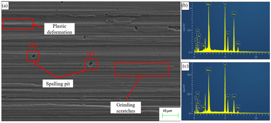
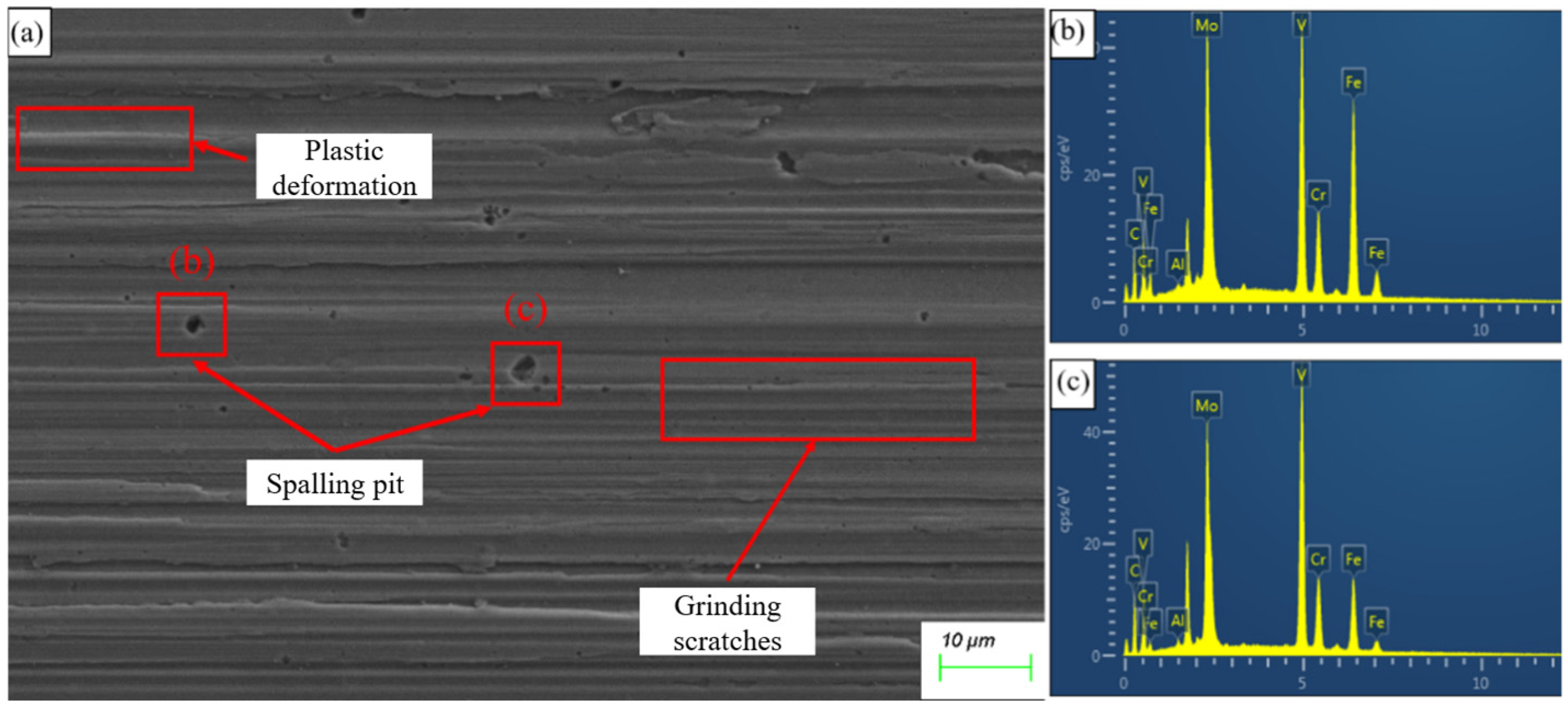
Figure 1a shows the ground surface morphology of 8Cr4Mo4V bearing steel under the conditions of a 20 μm grinding depth, 1 μm/s wheel feed rate, 38 m/s wheel linear speed, and 150 rpm workpiece rotation speed. Striated scratches along the grinding direction, resulting from abrasive grain extrusion, are clearly visible. Under load, plastic deformation occurred in the contact zone, forming irregular ridges and depressions. Several circular and irregular pits were also observed. EDS spectra of two such pits, shown in Figure 1b,c, indicate that these cavities resulted primarily from MC carbide particle spalling. No discoloration due to grinding burn was observed, possibly due to two factors: effective cooling during the experiment suppressed continuous oxidation and minimized visible discoloration; and any nanoscale oxide films present may be below the detection limit of the naked eye or optical microscopy.
Figure 1.
Ground surface morphology; (a) SEM image of the ground surface; (b,c) EDS spectra of spalling pits.
3.1.1. Analysis of Carbide Spalling Percentage on the Ground Surface
In the analysis of grinding surface defects, employing the carbide particle spalling area percentage (Sbf) to evaluate surface quality under different grinding parameters serves as a rational and effective approach. Sbf is calculated using threshold segmentation based on SEM images, defined as the ratio of the total area of spalling pits to the total measured area. This method intuitively reflects the spalling status of carbide particles on the surface during the grinding process, given that the severity of carbide spalling is closely correlated with surface quality. Consequently, this section analyzes the influence of different grinding parameters on the formation of surface defects from two perspectives: SEM morphological observation and the proportion of carbide spalling.
(1) Analysis of Carbide Spalling at Different Workpiece Rotation Speeds
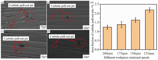
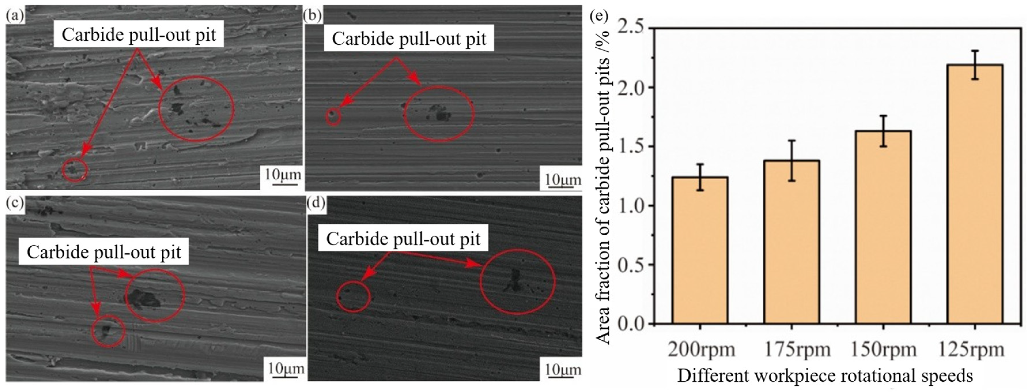
Figure 2a–d show SEM micrographs of ground surfaces at various workpiece rotation speeds, revealing the extent of particle spalling under each condition. At 200 rpm (Figure 2a), the surface is relatively smooth with minimal spalling and particle damage, indicating that higher rotation speeds reduce grinding force and thus limit carbide spalling. At 175 rpm (Figure 2b), spalling slightly increases, but the surface remains generally smooth. In contrast, at 150 rpm (Figure 2c), spalling becomes more pronounced with increased particle detachment and fragmentation, reflecting higher grinding force and surface roughness due to reduced speed. At 125 rpm (Figure 2d), the most severe spalling occurs, characterized by extensive detachment and fragmentation. This suggests that lower rotation speeds intensify friction between abrasive grains and the workpiece, leading to maximum particle damage and the poorest surface quality.
Figure 2.
Surface morphologies under different workpiece rotation speeds: (a) vw = 200 rpm; (b) vw = 175 rpm; (c) vw = 150 rpm; (d) vw = 125 rpm; (e) Area percentage of spalling pits at different workpiece rotation speeds.
Figure 2e presents the statistical results of the percentage of carbide spalling pits at different workpiece rotational speeds. It can be observed that the percentage of spalling area increases significantly as the workpiece rotational speed decreases, reaching its maximum at 125 rpm. This phenomenon can be explained by a thermo-mechanical coupling mechanism: lower workpiece rotational speeds prolong the contact time between individual abrasive grains and the workpiece, leading to an extended duration of thermal loading and localized temperature increases; simultaneously, the greater thickness of the undeformed chip increases the grinding force exerted on each abrasive grain. Under cyclic thermo-mechanical coupled loading, significant stress concentration occurs at the carbide-matrix interface due to their differing thermal expansion coefficients, ultimately triggering interface debonding and carbide particle spalling. This indicates that lower workpiece rotational speeds promote the occurrence of interface failure.
(2) Analysis of Carbide Spalling at Different Wheel Linear Speeds
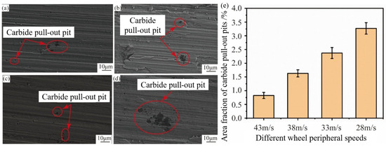
Figure 3a–d show SEM morphologies of ground surfaces at different wheel linear speeds (vs), revealing the surface characteristics under each condition. At 43 m/s (Figure 3a), the surface is relatively smooth with minimal particle breakage and detachment, indicating that higher grinding speeds reduce friction between abrasive grains and the workpiece, thereby limiting particle fragmentation and spalling. At 38 m/s (Figure 3b), slight particle detachment appears; although spalling has increased compared to 43 m/s, the surface remains relatively stable. At 33 m/s (Figure 3c), particle spalling becomes more distinct, with larger detachment areas and increased surface roughness, reflecting greater particle damage at lower grinding speeds. At 28 m/s (Figure 3d), the most severe spalling occurs, with obvious pits and detachment areas, suggesting that excessively low wheel speed leads to substantial grinding force, maximum particle fragmentation and spalling, and consequently poor surface quality.
Figure 3.
Surface morphologies under different wheel linear speeds: (a) vs = 43 m/s; (b) vs = 38 m/s; (c) vs = 33 m/s; (d) vs = 28 m/s; (e) Area percentage of spalling pits at different wheel linear speeds.
Figure 3e illustrates the area percentage of carbide spalling pits under different wheel linear speed conditions. As the wheel linear speed decreases, the area percentage of particle spalling gradually increases. Specifically, the spalling area percentage is at its minimum when the wheel linear speed is 43 m/s. Conversely, when the speed decreases to 28 m/s, the percentage reaches its maximum, approaching approximately 3.5%. This indicates that a lower linear speed results in a prolonged contact duration between the abrasive grains and the workpiece surface. This leads to an increased grinding force, causing more severe particle fragmentation and spalling, thereby deteriorating the quality of the ground surface. This trend is closely related to the interplay between thermal effects and mechanical stresses during the grinding process. A lower linear speed may induce a more intense interaction between the abrasive grains and the workpiece, generating higher local temperatures and stress concentration zones, which further promotes particle spalling.
In summary, the area percentage of particle spalling increases as the wheel linear speed decreases. This phenomenon is likely associated with the prolonged contact of abrasive grains at lower linear speeds, as well as the heat and stress generated during the grinding process. The reduced linear speed results in a longer contact duration between the abrasive grains and the workpiece, which increases the grinding force and exacerbates particle spalling, thereby deteriorating the surface quality. Therefore, the rational selection of wheel linear speed is crucial for controlling the quality of the ground surface.
(3) Analysis of Carbide Spalling at Different Wheel Feed Rates
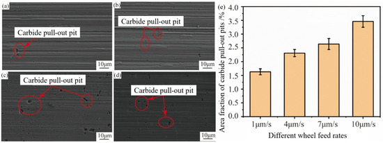
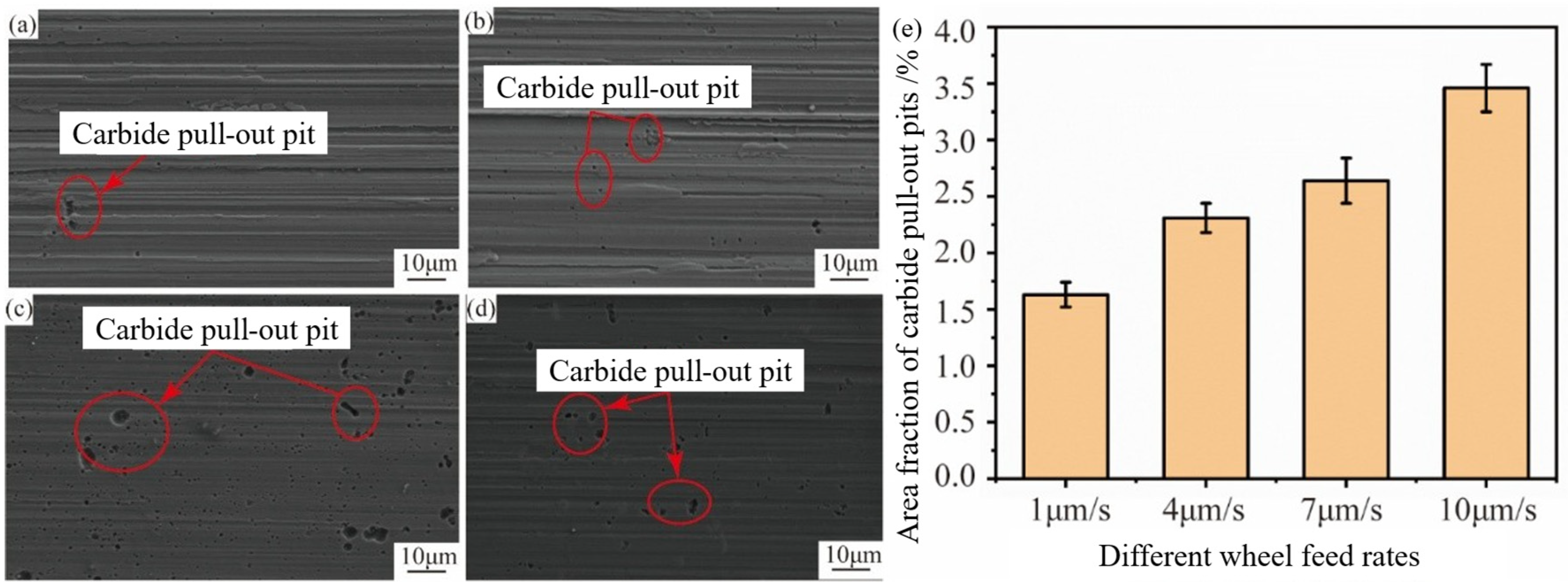
Figure 4a–d present the SEM morphologies of ground surfaces corresponding to different wheel feed rates, revealing the extent of particle spalling under each condition. In Figure 4a (feed rate of 1 μm/s), the surface appears relatively smooth with minimal particle damage and only a small amount of spalling. This indicates that at a low feed rate, the grinding force is low, resulting in fewer instances of particle fragmentation and spalling. In Figure 4b (feed rate of 4 μm/s), the phenomenon of particle spalling shows a slight increase. Although the surface remains relatively smooth, the spalling regions have expanded compared to the 1 μm/s condition. As shown in Figure 4c (feed rate of 7 μm/s), particle spalling increases significantly, with the surface exhibiting more irregular detachment zones. This reflects that at higher feed rates, the grinding force increases, thereby intensifying particle spalling and fragmentation. Finally, Figure 4d (feed rate of 10 μm/s) exhibits the most severe particle spalling, characterized by obvious particle detachment and fragmentation. This demonstrates that at higher feed rates, the friction and pressure between the abrasive grains and the workpiece surface are substantial, leading to the most severe particle spalling.
Figure 4.
Surface morphologies under different wheel feed rates: (a) vf = 1 μm/s; (b) vf = 4 μm/s; (c) vf = 7 μm/s; (d) vf = 10 μm/s; (e) Area percentage of spalling pits at different wheel feed rates.
Figure 4e presents the statistical results of the percentage area of carbide spalling pits at different grinding wheel feed rates. It can be observed that the percentage of spalling area increases significantly with higher feed rates, reaching a maximum value (approximately 0.035) at 10 μm/s. This phenomenon is closely related to the thermo-mechanical coupling effect during grinding: higher feed rates remove more material per unit time, significantly intensifying grinding forces and mechanical impacts, thereby exacerbating stress concentration at the carbide-matrix interface. Simultaneously, rapid feed promotes heat accumulation, elevating local temperatures and generating substantial thermal gradients, which further induce thermal mismatch stresses at the interface. Under the combined action of cyclic thermal–mechanical loading, the carbide-matrix interface becomes more susceptible to debonding and microcrack propagation, ultimately manifesting as more severe particle spalling. Thus, increasing feed rate accelerates interface failure primarily through two pathways: intensifying mechanical impact and exacerbating thermal accumulation.
Based on the above analysis, it is evident that the wheel feed rate has a significant influence on the area percentage of particle spalling. Higher feed rates increase the grinding force, leading to greater particle fragmentation and spalling, which in turn affects the surface quality. Therefore, the rational selection of the wheel feed rate is of great significance for controlling particle spalling and improving the ground surface quality. In practical machining applications, an appropriate feed rate should be selected based on the material properties and processing requirements to achieve superior surface quality.
(4) Analysis of Carbide Spalling at Different Grinding Depths
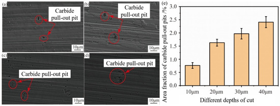
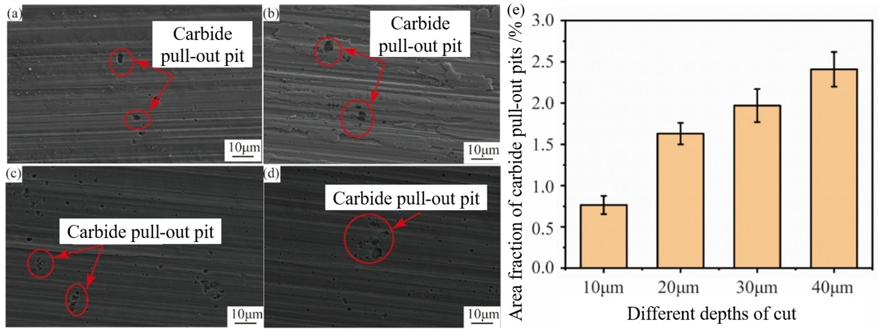
Figure 5a–d present the SEM morphologies of ground surfaces corresponding to different grinding depths (ap), revealing the extent of particle spalling under each condition. In Figure 5a (grinding depth of 10 μm), the surface appears relatively smooth with minimal particle spalling. This indicates that a smaller grinding depth results in lighter grinding forces, leading to less particle damage. In Figure 5b (grinding depth of 20 μm), particle spalling shows a slight increase, and the surface exhibits more detachment zones. This suggests that as the grinding depth increases, the phenomenon of particle damage gradually intensifies. As shown in Figure 5c (grinding depth of 30 μm), particle spalling becomes more distinct, with larger areas of particle detachment appearing on the surface. This reflects that with a further increase in grinding depth, the spalling area expands, and surface roughness increases. Finally, Figure 5d (grinding depth of 40 μm) exhibits the most significant particle spalling, characterized by obvious areas of detachment and fragmentation. This demonstrates that a larger grinding depth leads to increased particle detachment and fragmentation.
Figure 5.
Surface morphologies under different grinding depths: (a) ap = 10 μm; (b) ap = 20 μm; (c) ap = 30 μm; (d) ap = 40 μm; (e) Area percentage of spalling pits at different grinding depths.
Figure 5e illustrates the area percentage of carbide spalling pits under different grinding depths. As evident from the bar chart, the area percentage of particle spalling exhibits a gradually increasing trend with the increase in grinding depth. Specifically, at a grinding depth of 10 μm, the particle spalling area percentage is minimal, whereas when the grinding depth increases to 40 μm, the percentage reaches its maximum, approaching approximately 0.025 (2.5%). This indicates that a deeper grinding depth results in higher grinding forces and a larger grinding contact area, thereby inducing more particle fragmentation and spalling. Increased grinding depths lead to greater friction and higher local temperatures, which further promote the spalling of particles.
Based on the experimental results, the grinding depth has a significant influence on the area percentage of particle spalling. As the grinding depth increases, the phenomenon of particle spalling intensifies, leading to the deterioration of surface quality. This is attributed to the fact that a deeper grinding depth increases the grinding force and local stress, thereby promoting particle fragmentation and spalling. Therefore, in practical grinding processes, it is essential to select an appropriate grinding depth to mitigate particle spalling and achieve a high-quality surface.
Among all the aforementioned grinding parameters, the wheel linear speed exerts the most significant influence on carbide spalling. The area percentage of carbide spalling increases as the wheel linear speed decreases, indicating that a lower linear speed amplifies the grinding force, leading to increased particle fragmentation and spalling. Consequently, the wheel linear speed is identified as the critical parameter for controlling carbide spalling. The appropriate selection of wheel linear speed is of great significance for optimizing the grinding process and enhancing surface quality.
3.1.2. Morphological Analysis of Spalling Pits on the Ground Surface
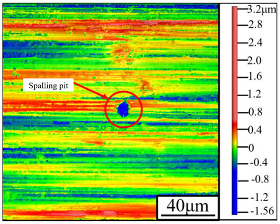
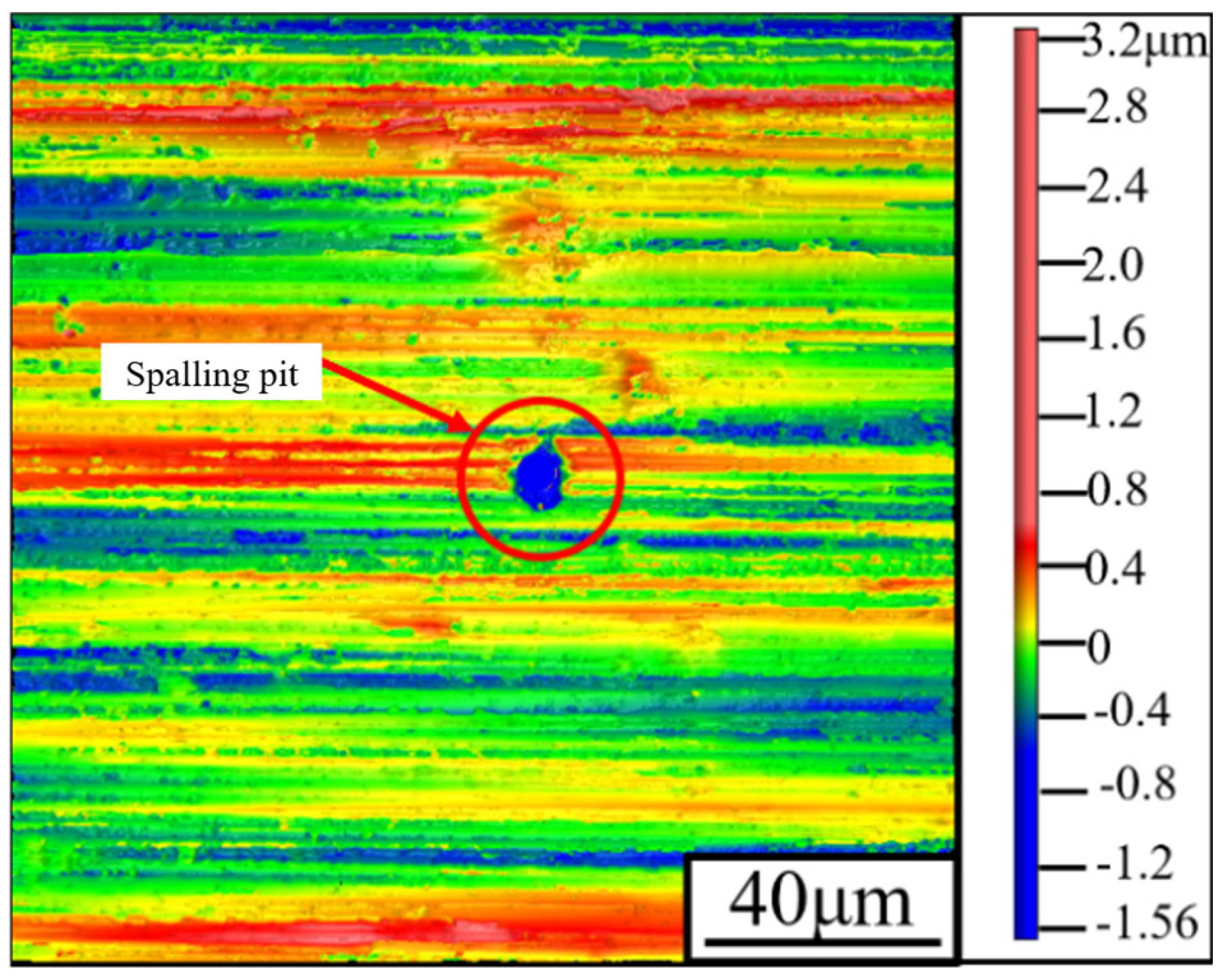
Figure 6 displays the ground surface morphology of the 8Cr4Mo4V bearing steel under the grinding parameters of (vs = 38 m/s, vw = 150 rpm, vf = 1 μm/s, ap = 20 μm). Distinct carbide spalling pits are clearly observed on the ground surface. The color variations in the White Light Interferometry (WLI) image reveal the non-uniformity of the surface height; specifically, red regions represent surface peaks (higher areas), while blue regions represent valleys (lower areas). Significant surface undulation is evident, particularly in the vicinity of carbide particles. This is attributed to uneven material removal or insufficient local grinding force during the grinding process. Although the overall surface remains relatively flat, local irregularities and the formation of spalling pits persist.
Figure 6.
Ground surface morphology of bearing steel showing pit features.
(1) Analysis of 3D Morphology of Spalling Pits at Different Workpiece Rotation Speeds
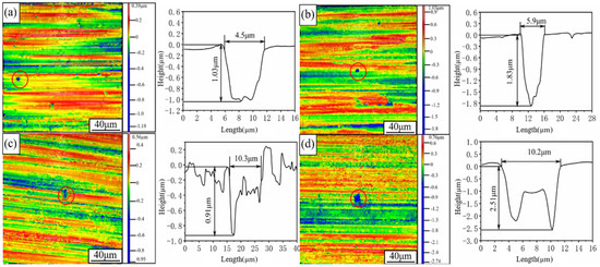
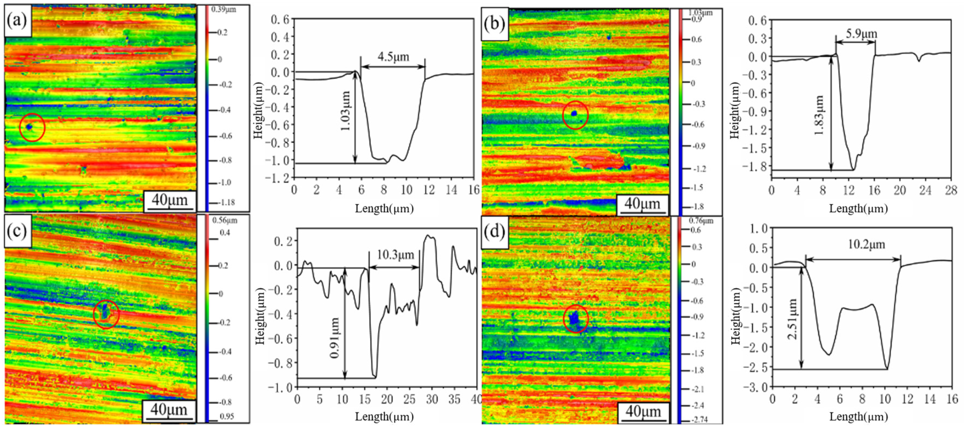
Figure 7 presents the 3D morphologies of carbide spalling pits and their corresponding cross-sectional profiles obtained from grinding experiments under different workpiece rotation speeds (vw), with Figure 7a–d corresponding to 200 rpm, 175 rpm, 150 rpm, and 125 rpm, respectively. When the workpiece rotation speed is high (200 rpm), fewer carbides spall, and the resulting pits are relatively shallow and uniformly distributed, with a depth of approximately 1.03 μm and a length of 4.5 μm. This indicates that a higher rotation speed reduces the contact duration between the grinding wheel and the bearing steel, resulting in smaller and shallower carbide spalling pits. When the rotation speed decreases to 175 rpm, the number of spalling pits increases slightly, and the pit depth increases to 1.85 μm, with a length of 5.9 μm. This suggests that the lower rotation speed increases the grinding contact time, causing grinding forces to concentrate in local areas; consequently, this intensifies the carbide spalling phenomenon, increasing both the depth and length of the pits. With a further reduction in workpiece rotation speed, the contact time between the workpiece and abrasive grains increases further, leading to large-area spalling of surface carbides and the formation of larger pits. Specifically, when the workpiece rotation speed reaches 125 rpm, the spalling pit depth increases to 2.51 μm, and the length extends to 10.2 μm.
Figure 7.
Morphologies of spalling pits at different workpiece rotation speeds: (a) vw = 200 rpm; (b) vw = 175 rpm; (c) vw = 150 rpm; (d) vw = 125 rpm.
Based on the above analysis, as the workpiece rotational speed decreases, the number, depth, and width of carbide spalling pits all increase significantly. This phenomenon stems from the direct impact of reduced rotational speed on the thermal–mechanical coupling mechanism during grinding: lower workpiece speeds not only prolong the contact time between individual abrasive grains and the workpiece, leading to sustained accumulation of grinding heat in the surface layer and resulting in higher temperature gradients and thermal stresses; they also increase the thickness of undeformed chips, causing a significant rise in mechanical loads. Under the coupled thermal–mechanical cycling, the interface between carbides and the matrix experiences more severe stress concentration due to differing thermal expansion coefficients, accelerating debonding and crack propagation, manifested as more severe particle spalling. Conversely, higher rotational speeds help shorten thermal exposure time and reduce mechanical impact, thereby suppressing spalling occurrence. Therefore, reduced workpiece rotational speed significantly accelerates interface failure processes by intensifying the synergistic effects of thermal accumulation and mechanical loading, leading to diminished surface integrity.
(2) Analysis of 3D Morphology of Spalling Pits at Different Wheel Linear Speeds
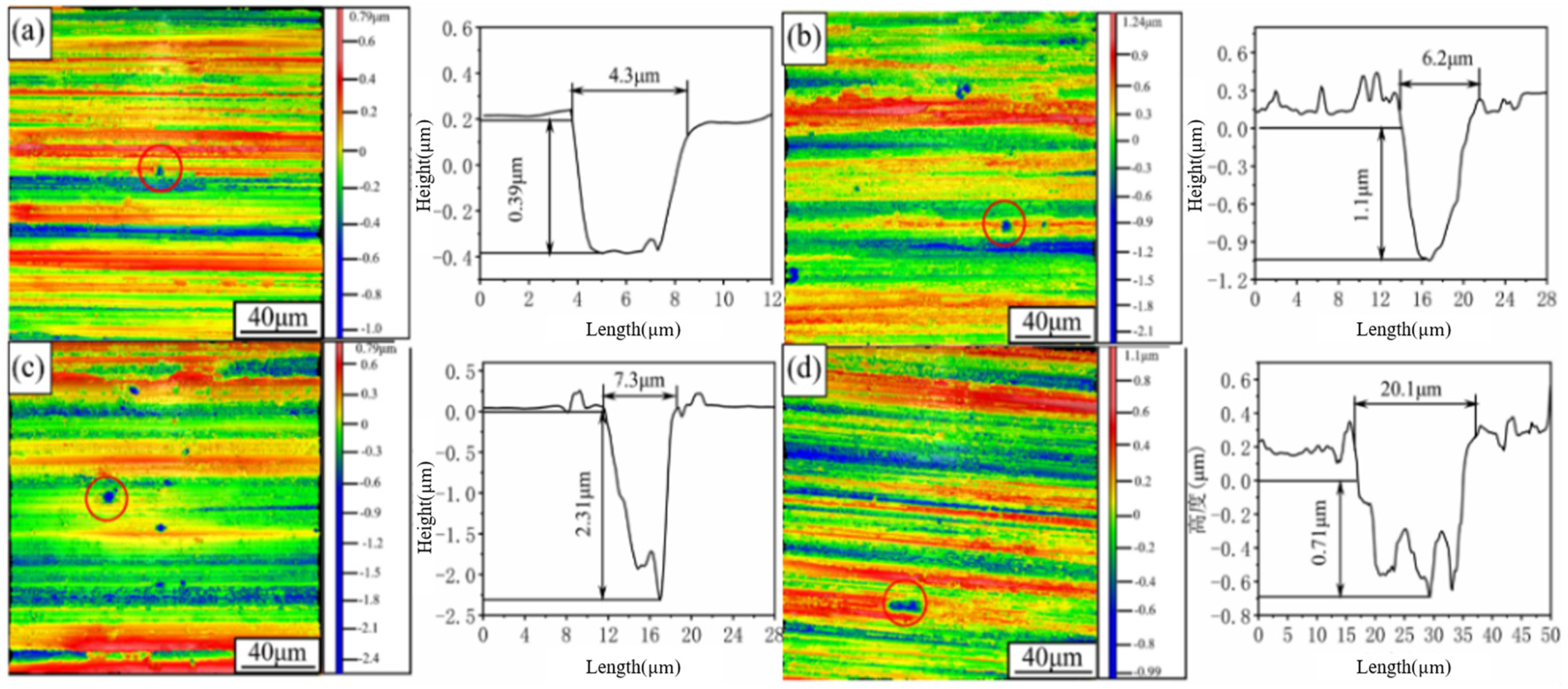
Figure 8 displays the 3D morphologies of carbide spalling pits and their corresponding cross-sectional profiles obtained from grinding experiments under different wheel linear speeds (vs). Figure 8a–d correspond to wheel linear speeds of 43 m/s, 38 m/s, 33 m/s, and 28 m/s, respectively. At higher wheel linear speeds, carbide spalling pits are relatively scarce. The pits are shallow, with a depth of approximately 0.39 μm and a size of 4.3 μm. This indicates that a higher wheel linear speed provides superior grinding performance. Less heat is generated during the grinding process, preventing excessive heat accumulation. Consequently, this reduces the phenomenon of carbide spalling, resulting in smaller pit depths and dimensions. Conversely, when the wheel linear speed decreases to 28 m/s, the length of the spalled carbide increases to 20.1 μm, and the depth increases to 0.71 μm. In summary, as the wheel linear speed decreases, the quantity, depth, and width of the carbide spalling pits increase significantly. This suggests that a lower wheel linear speed leads to higher accumulation of heat and friction, thereby exacerbating carbide spalling. Conversely, a higher wheel linear speed helps reduce heat accumulation and mitigate carbide spalling, resulting in relatively smaller pit depths and widths. Overall, a higher wheel linear speed is beneficial for minimizing the formation of carbide spalling pits, thereby improving surface quality.
Figure 8.
Morphologies of spalling pits at different wheel linear speeds: (a) vs = 43 m/s; (b) vs = 38 m/s; (c) vs = 33 m/s; (d) vs = 28 m/s.
(3) Analysis of 3D Morphology of Spalling Pits at Different Wheel Feed Rates
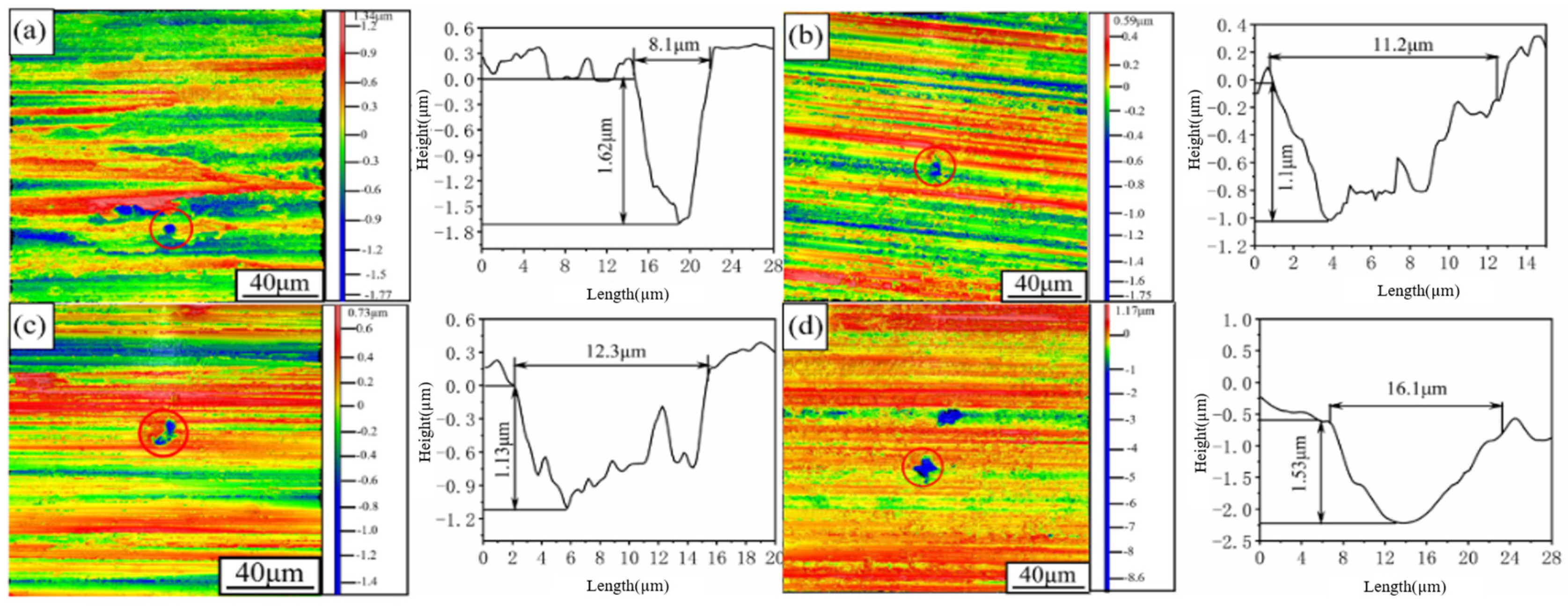
Figure 9 presents the 3D morphologies and profile characteristics of carbide spalling pits under different wheel feed rate (vf) conditions. Figure 9a–d correspond to the four feed rate conditions of 1 μm/s, 4 μm/s, 7 μm/s, and 10 μm/s, respectively. When the wheel feed rate is 1 μm/s (Figure 9a), the spalling pits on the surface are sparsely distributed, with an average depth of 1.62 μm and a characteristic dimension of 8.1 μm, indicating relatively superior overall surface quality. As the feed rate increases to 4 μm/s (Figure 9b), the number of spalling pits increases noticeably, and their size also enlarges slightly. This trend becomes more pronounced at the 7 μm/s condition (Figure 9c), indicating that the increase in feed rate exacerbates the carbide spalling behavior. Notably, when the feed rate reaches 10 μm/s (Figure 9d), the spalling pit depth decreases slightly to 1.53 μm, but the characteristic dimension increases to 16.1 μm. This phenomenon can be attributed to the fact that under high feed rate conditions, the shortened grinding contact time leads to rapid heat accumulation in local areas, while the insufficient time for heat dissipation further promotes the spalling of carbide particles. Simultaneously, although the higher feed rate does not cause excessive concentration of grinding forces, the transient thermal shock effect is significantly enhanced.
Figure 9.
Morphologies of spalling pits at different wheel feed rates: (a) vf = 1 μm/s; (b) vf = 4 μm/s; (c) vf = 7 μm; (d) vf = 10 μm/s.
Experimental results indicate a significant correlation between grinding wheel feed rate and carbide spalling behavior. At lower feed rates (1–4 μm/s), the extended duration of each grinding pass allows for more thorough dissipation of grinding heat. This mitigates surface heat accumulation and thermal stress concentration, resulting in reduced spalling severity. At higher feed rates (7–10 μm/s), the material removal rate per unit time increases significantly, leading to a sharp rise in the intensity of thermal–mechanical coupling. This not only induces greater mechanical impact but also exacerbates local temperature rise and thermal gradients. Consequently, the carbide/matrix interface becomes more susceptible to debonding and propagation under cyclic thermal stresses, resulting in a significant increase in both the number and size of spalling pits. This pattern indicates that rational control of feed rate is crucial for regulating thermal–mechanical loads during grinding and suppressing interface failure. Excessively high feed rates significantly degrade surface integrity due to intense thermal–mechanical coupling effects.
(4) Analysis of 3D Morphology of Spalling Pits at Different Grinding Depths
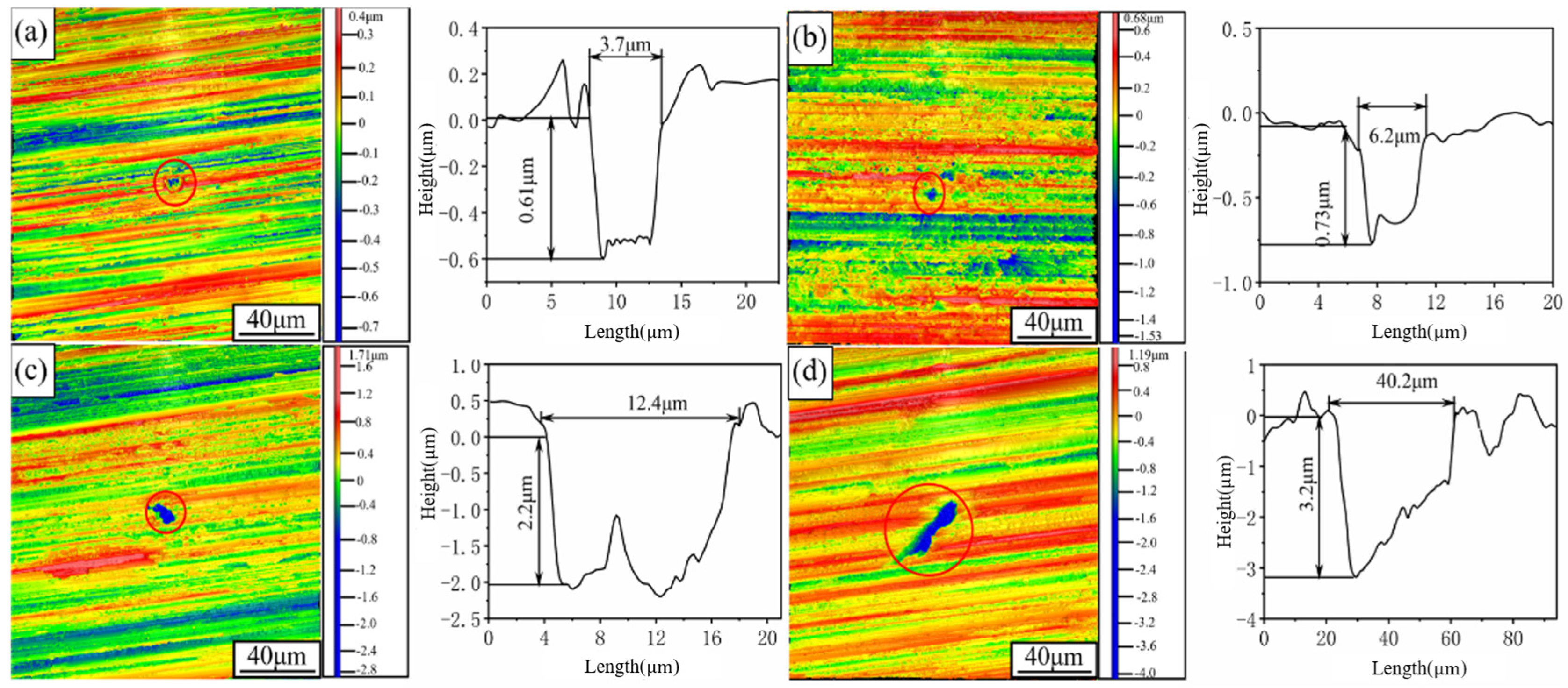
Figure 10 shows the 3D morphologies and cross-sectional profiles of carbide spalling pits at different grinding depths (ap), with Figure 10a–d corresponding to 10, 20, 30, and 40 μm, respectively. At 10 μm (Figure 10a), the spalling pits are small, measuring only 0.61 μm in depth and 3.7 μm in length. The surface remains relatively smooth with sparse pit distribution, indicating that a shallow grinding depth causes limited damage to carbide particles. As the depth increases to 20 μm (Figure 10b), both pit depth and length increase noticeably to 0.73 μm and 6.2 μm, respectively. Compared to 10 μm, the pit dimensions expand significantly, suggesting that greater grinding depth intensifies grinding forces, promoting carbide particle fracture and spalling. At 30 μm (Figure 10c), pit dimensions further increase to 2.2 μm in depth and 12.4 μm in length. The surface morphology exhibits more pronounced spalling features, indicating that deeper grinding exacerbates grinding force effects and local stress concentration, triggering more severe particle fragmentation and spalling. At the maximum depth of 40 μm (Figure 10d), spalling pits reach their largest dimensions, with a depth of 3.2 μm and a length extending to 40.2 μm. Extensive carbide spalling and fragmentation appear on the surface, demonstrating that under deep grinding conditions, the combined effects of grinding force and thermal action significantly alter the material removal mechanism, resulting in large-scale destruction of hard phase particles.
Figure 10.
Morphologies of spalling pits at different grinding depths: (a) ap = 10 μm; (b) ap = 20 μm; (c) ap = 30 μm; (d) ap = 40 μm.
In summary, the grinding depth has a decisive influence on the formation of carbide spalling pits. As the grinding depth increases, both the depth and length of the spalling pits show an increasing trend, and the surface spalling phenomenon becomes more pronounced. This pattern indicates that deep grinding enhances the grinding force and stress concentration effects, thereby exacerbating the fragmentation and spalling of carbide particles.
3.2. Analysis of Grinding Subsurface Defects
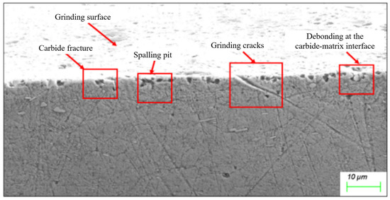
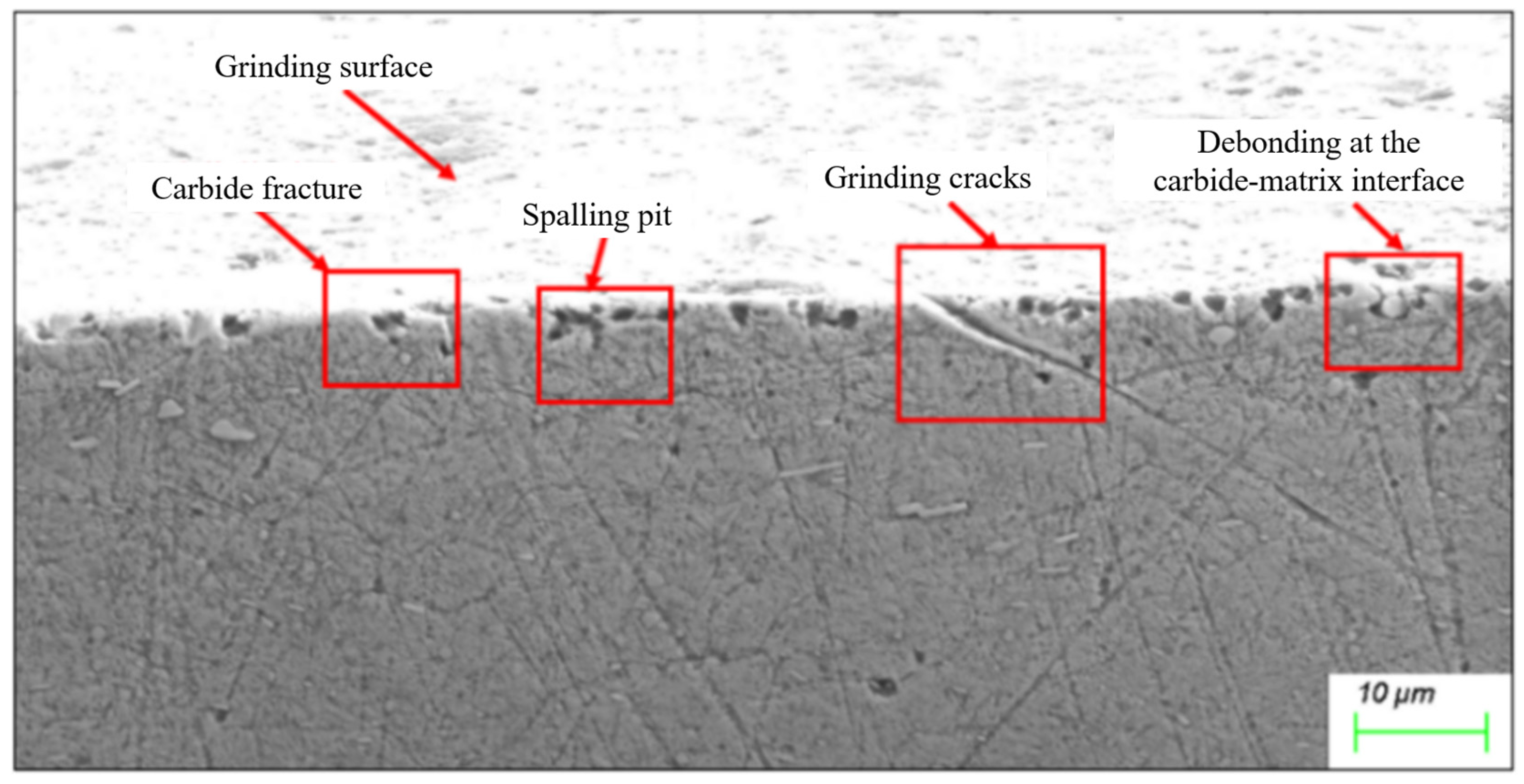
Figure 11 presents the SEM micrograph of the workpiece subsurface under the grinding conditions of a wheel linear speed of 38 m/s, a feed rate of 1 μm/s, a workpiece rotation speed of 150 rpm, and a grinding depth of 20 μm. It is clearly visible from the figure that after the grinding process, subsurface damage manifests in various forms, including grinding cracks, carbide fragmentation, and carbide spalling pits. Due to the significant difference in mechanical properties between the carbide particles and the matrix, local stress concentration occurs during grinding, leading to the detachment of carbides from the ground surface. Furthermore, carbides possess high brittleness. Consequently, some fragmented carbides are not completely detached from the matrix; instead, some merely undergo interfacial debonding from the matrix while remaining embedded within it. Through cross-sectional observation, it is evident that grinding cracks initiate from the machined surface and extend inward. Moreover, in certain carbide spalling pits, there is a distinct tendency for defects to propagate inward. Thus, it can be inferred that the initiation of subsurface micro-cracks originates from carbide spalling and propagates into the interior along the spalling pits.
Figure 11.
Subsurface morphology under grinding parameters of vs = 38 m/s, vf = 1 μm/s, ap = 20 μm, vw = 150 rpm.
(1) Analysis of Grinding Cracks at Different Workpiece Rotation Speeds
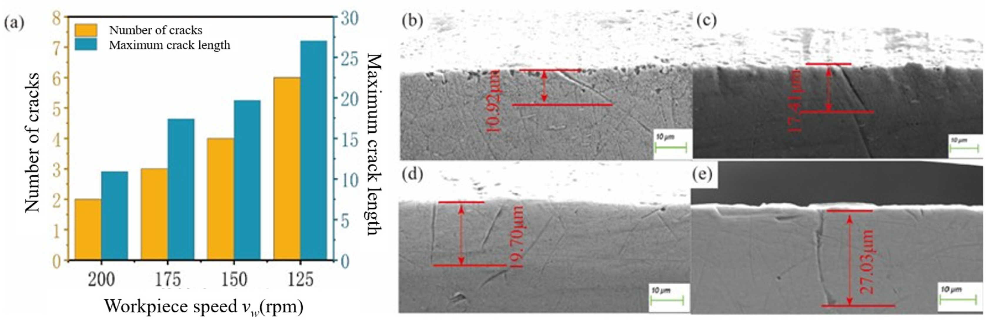
Figure 12 presents statistical results of subsurface cracks at different workpiece rotational speeds. It can be observed that workpiece rotational speed significantly influences the initiation and propagation of grinding cracks. At higher speeds (e.g., 200 rpm), the number of cracks, maximum crack length, and subsurface crack depth remain at low levels. Crack density is reduced, and the heat-affected zone thickness is thinner. This indicates that high rotational speeds help mitigate thermal accumulation and stress levels during grinding, thereby effectively suppressing crack formation. As the workpiece speed gradually decreased (e.g., 175 rpm, 150 rpm, and 125 rpm), the number and length of cracks increased significantly. Concurrently, the maximum subsurface crack depth, crack density, and heat-affected zone thickness also showed a synchronous upward trend. At 125 rpm, crack count peaked, with maximum crack length extending to 27.03 μm. Crack morphology evolved from shallow surface microcracks to deep, elongated cracks, accompanied by pronounced thermal damage or embrittlement characteristics.
Figure 12.
(a) Statistical chart of cracks at different workpiece rotation speeds; Crack morphologies at different workpiece rotation speeds: (b) vw = 200 rpm; (c) vw = 175 rpm; (d) vw = 150 rpm; (e) vw = 125 rpm.
These trends indicate that sustained accumulation of grinding force and heat at low speeds elevates surface temperature, inducing significant thermal stress that promotes crack nucleation and propagation, while stress concentration further exacerbates crack initiation. Scanning electron microscope images clearly depict the evolution of cracks from short and shallow to deep and elongated, revealing the gradual accumulation of thermal damage in the surface layer. Overall, reducing workpiece speed significantly increases the number, depth, and distribution density of grinding cracks, with the thermal–mechanical coupling effect being the primary cause of subsurface damage. Therefore, rationally optimizing workpiece rotational speed and avoiding excessively low settings is an effective approach to enhance grinding surface integrity and reduce crack defects.
(2) Analysis of Grinding Cracks at Different Wheel Linear Speeds
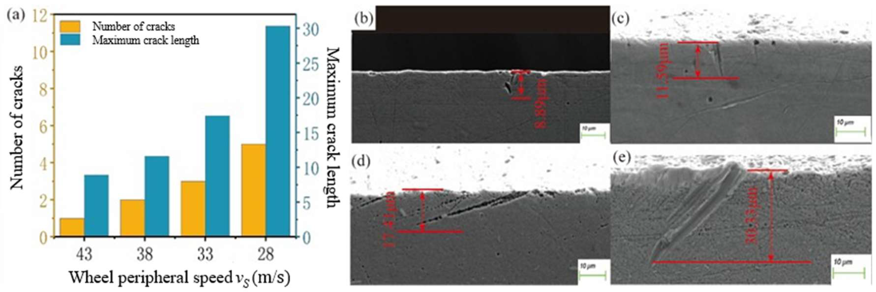
Figure 13 presents statistical data on subsurface cracks at different wheel linear speeds (vs), revealing its significant influence on crack initiation and propagation during grinding. As shown in the bar chart (Figure 13a), both crack quantity and maximum length increase considerably with decreasing wheel linear speed, reaching their maximum at 28 m/s. The SEM micrographs (Figure 13b–e) further reveal that as wheel speed decreases, crack morphology evolves from relatively short, shallow micro-cracks to longer and deeper cracks, accompanied by distinct thermal damage. At 43 m/s, crack length is only 8.89 μm with no observable thermal damage, indicating that higher wheel speed effectively suppresses crack initiation and propagation. However, as wheel speed reduces, crack length progressively increases, reaching 30.33 μm at 28 m/s, with clear characteristics of thermal cracking and embrittlement. The increased thermal effects and stress concentration at low wheel speeds induce material surface embrittlement, thereby elevating crack formation risk. Thus, higher wheel linear speeds help minimize crack quantity and length, while lower speeds tend to promote crack generation. Therefore, selecting an appropriate wheel linear speed—particularly avoiding excessively low speeds when grinding hard materials—is conducive to reducing crack formation and improving grinding quality. Other parameters such as grinding depth and feed rate should also be considered alongside adequate cooling measures to optimize surface quality.
Figure 13.
(a) Statistical chart of cracks at different wheel linear speeds; Crack morphologies at different wheel linear speeds: (b) vs = 43 m/s; (c) vs = 38 m/s; (d) vs = 33 m/s; (e) vs = 28 m/s.
(3) Analysis of Grinding Cracks at Different Wheel Feed Rates
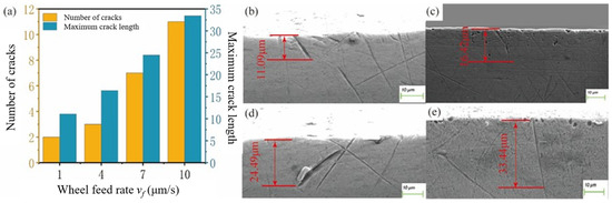
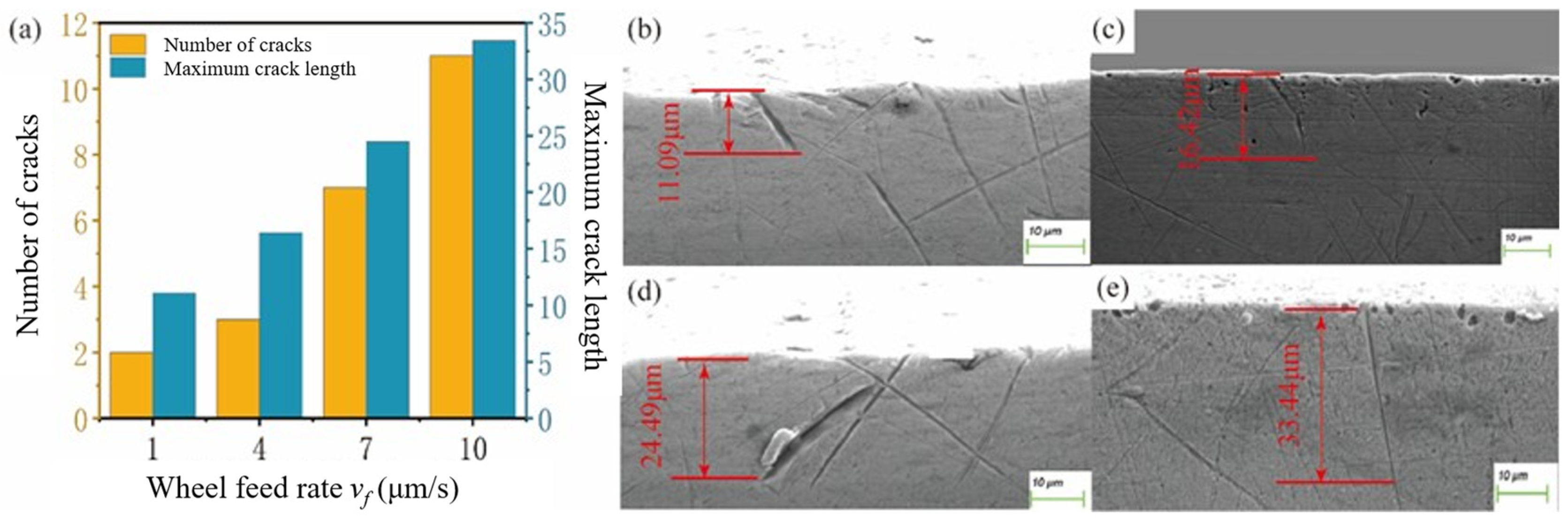
Figure 14 presents statistical characteristics of subsurface cracks in ground 8Cr4Mo4V bearing steel under different wheel feed rates, revealing its decisive influence on crack initiation, propagation, and damage morphology. As shown in the bar chart (Figure 14a), increasing the feed rate from 1 to 10 μm/s leads to a monotonic increase in subsurface crack density, with crack count rising by approximately 3.2 times. Meanwhile, maximum crack length substantially grows from 11.09 to 33.44 μm—an increase of over 300%. Notably, when the feed rate exceeds 5 μm/s, both crack quantity and length accelerate significantly, suggesting a critical threshold beyond which material damage deteriorates rapidly. Comparative SEM micrographs (Figure 14b–e) intuitively reveal the feed rate-driven evolution of crack morphology. At 1 μm/s, cracks appear as short, shallow micro-cracks with an average length below 10 μm, relatively straight propagation paths, and minor surface damage. In contrast, at 10 μm/s, crack morphology changes markedly: numerous main cracks exceeding 30 μm appear, accompanied by complex networks of secondary branching cracks, significantly increased crack depth, and even localized material spalling. Based on these findings, clear process optimization recommendations emerge: in practical grinding operations, the wheel feed rate should be controlled below 5 μm/s. This parameter range maintains machining efficiency while effectively suppressing excessive crack propagation.
Figure 14.
(a) Statistical chart of cracks at different wheel feed rates; Crack morphologies at different wheel feed rates: (b) vf = 1 μm/s; (c) vf = 4 μm/s; (d) vf = 7 μm/s; (e) vf = 10 μm/s.
(4) Analysis of Grinding Cracks at Different Grinding Depths
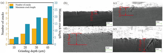
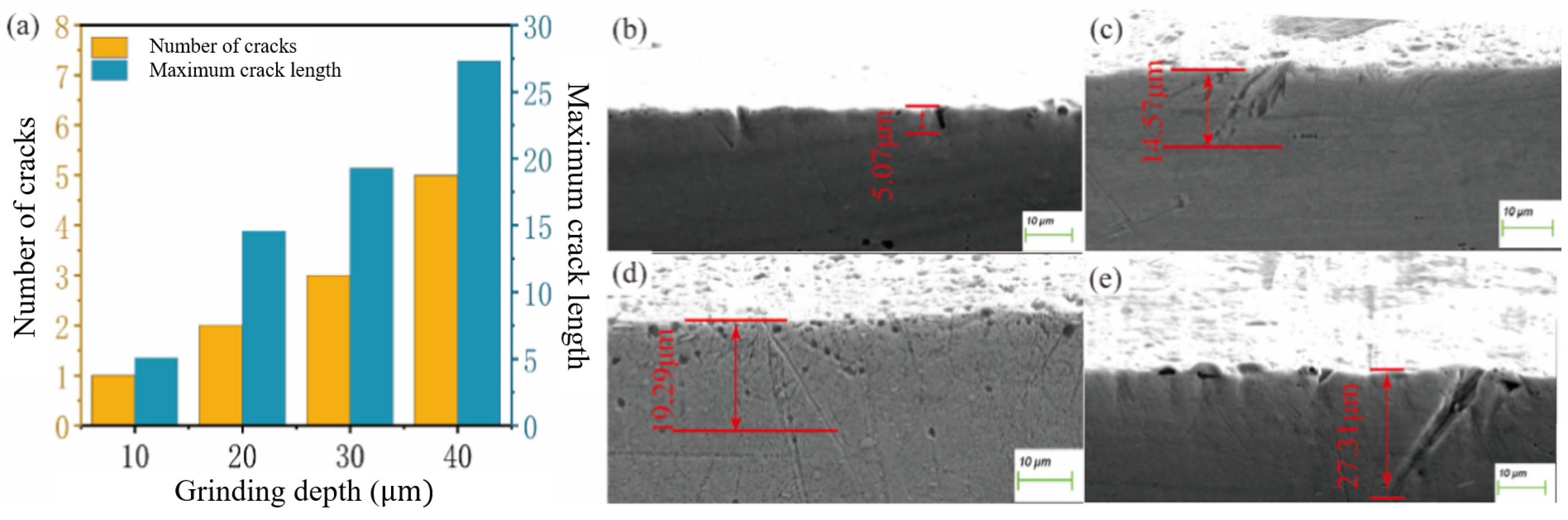
Figure 15 presents statistical data on subsurface cracks at different grinding depths, revealing a significant upward trend in both crack quantity and maximum length as grinding depth increases from 10 μm to 40 μm. The bar chart (Figure 15a) shows the variations in these metrics, highlighting substantial increases at greater depths. SEM micrographs (Figure 15b–e) further illustrate the morphological evolution of cracks. At a shallow grinding depth, cracks are relatively short (approximately 5.07 μm). However, as depth increases, cracks progressively propagate, reaching 27.31 μm while exhibiting distinct thermal damage and plastic deformation. This crack propagation is primarily attributed to the elevated cutting forces and heat accumulation associated with larger grinding depths. The resulting stress concentration induces surface cracking, which intensifies with increasing depth. Greater grinding depths increase both forces and temperatures, leading to brittle fracture of the material surface, with cracks propagating across the surface and gradually penetrating deeper. Therefore, to minimize crack formation during grinding, the grinding depth should be rationally controlled to avoid material embrittlement and excessive crack propagation. Overall, appropriate selection of grinding parameters—particularly grinding depth—can effectively reduce crack generation and enhance ground surface quality.
Figure 15.
(a) Statistical chart of cracks at different grinding depths; Crack morphologies at different grinding depths: (b) ap = 10 μm; (c) ap = 20 μm; (d) ap = 30 μm; (e) ap = 40 μm.
To further quantitatively evaluate subsurface damage behavior, subsequent studies should systematically measure the correlation between maximum crack depth and grinding parameters, crack density, and affected layer thickness. This will support precise process parameter control and the establishment of damage suppression models.
4. Conclusions
In this paper, the grinding defects of 8Cr4Mo4V bearing steel were investigated through grinding experiments and microscopic characterization. The main conclusions are drawn as follows:
(1) Fragmentation and spalling of MC carbide particles are the primary forms of surface defects. Experimental results indicate that the degree of carbide spalling is closely correlated with grinding parameters: it exhibits a negative correlation with workpiece rotation speed and wheel linear speed, while showing a positive correlation with wheel feed rate and grinding depth. Among these parameters, the wheel linear speed is the most significant process variable affecting the degree of carbide spalling. This is primarily attributed to the prolonged contact time between abrasive grains and the workpiece, which intensifies the thermo-mechanical coupling effect in the grinding zone. The induced local temperature rise and stress concentration lead to the brittle fracture of the hard carbide phase and its detachment from the matrix.
(2) Subsurface defects are dominated by micro-cracks. Subsurface cracks mainly originate from carbide spalling pits and exhibit characteristics of propagating into the material interior along the grinding direction. The propagation behavior of cracks is closely associated with grinding parameters: decreasing the workpiece rotation speed and wheel linear speed, as well as increasing the wheel feed rate and grinding depth, result in an increase in both the quantity and length of grinding cracks. Notably, the grinding depth has the most significant impact on subsurface cracks. This is because a larger grinding depth increases grinding forces and temperatures, leading to brittle fracture of the material surface, with cracks propagating across the surface and gradually penetrating deeper.
In summary, to simultaneously control surface carbide spalling and subsurface crack generation, a combination of higher wheel linear speed and workpiece rotation speed, coupled with lower wheel feed rate and grinding depth, should be adopted. This combination can reduce the cutting load of single abrasive grains and heat accumulation in the grinding zone, thereby achieving superior ground surface integrity.
Two primary limitations remain in the current study: First, damage identification and parameter determination rely to some extent on manual judgment. Future research may incorporate machine vision and automated statistical methods to achieve more objective and efficient identification analysis. Second, existing experiments are based on single-factor designs, whereas the actual grinding process is a typical multi-parameter strongly coupled process. Therefore, subsequent work will focus on examining the interactive effects among multiple parameters. We plan to incorporate modeling techniques such as response surface methodology to systematically investigate the coupled mechanisms by which process parameters influence damage formation.
Author Contributions
Conceptualization, J.L., H.Z., H.L. and X.S.; methodology, J.L., H.Z., Z.Z., H.L. and X.S.; software, J.L., H.Z., C.S. and X.S.; validation, J.L., B.Z. and H.L.; formal analysis, J.L., H.Z., Z.Z. and H.L.; investigation, C.S. and B.Z.; resources, H.L. and X.S.; data curation, J.L. and C.S.; writing—original draft preparation, J.L. and H.Z.; writing—review and editing, X.S. and H.L.; visualization, J.L., H.Z. and Z.Z.; supervision, B.Z. and C.S.; project administration, X.S., B.Z., Y.S. and H.L.; funding acquisition, X.S., Y.S. and H.L. All authors have read and agreed to the published version of the manuscript.
Funding
This research was funded by the Major Program of the National Natural Science Foundation of China (No. 52031003).
Data Availability Statement
The raw data supporting the conclusions of this article will be made available by the authors on request.
Conflicts of Interest
The authors declare no conflicts of interest.
References
- Bhadeshia, H.K.D.H. Steels for Bearings. Prog. Mater. Sci. 2012, 57, 268–435. [Google Scholar] [CrossRef] [Scilit]
- Xu, F.; Ding, N.; Li, N.; Liu, L.; Hou, N.; Xu, N.; Guo, W.; Tian, L.; Xu, H.; Lawrence Wu, C.-M.; et al. A Review of Bearing Failure Modes, Mechanisms and Causes. Eng. Fail. Anal. 2023, 152, 107518. [Google Scholar] [CrossRef] [Scilit]
- Liu, X.; Xia, T.; Li, H.; Song, T.; Qu, N.; Liu, Y.; Zhu, J. Microstructure Evolution and Mechanical Properties of Grinding Metamorphic for 8Cr4Mo4V Steel. Materials 2025, 18, 1092. [Google Scholar] [CrossRef] [Scilit] [PubMed]
- Jiang, H.; Song, Y.; Wu, Y.; Shan, D.; Zong, Y. Macrostructure, Microstructure and Mechanical Properties Evolution during 8Cr4Mo4V Steel Roller Bearing Inner Ring Forging Process. Mater. Sci. Eng. A 2020, 798, 140196. [Google Scholar] [CrossRef] [Scilit]
- Zhang, B.; Liu, H.; Zhang, M.; Dai, C.; Xie, Z.; Ma, X.; Sun, Y. New Layering Strategy and the Gradient Microstructure Distribution of Surface Metamorphic Layer for 8Cr4Mo4V Steel by Grinding. Arch. Civ. Mech. Eng. 2024, 24, 42. [Google Scholar] [CrossRef] [Scilit]
- Klocke, F.; Barth, S.; Mattfeld, P. High Performance Grinding. Procedia CIRP 2016, 46, 266–271. [Google Scholar] [CrossRef] [Scilit]
- He, W.; Zeng, Q.; Xiao, Q.; Pang, Z.; Wu, Y.; Yan, C.; Huang, S.; Zhuang, J.; Wang, J.; Li, H.; et al. Evolution of Wetted and Corroded Areas on 8Cr4Mo4V Bearing Steel Exposed to Salt Water Contaminated Lubricant Oil. Corros. Sci. 2024, 241, 112515. [Google Scholar] [CrossRef] [Scilit]
- Yang, L.; Xue, W.; Gao, S.; Li, L.; Cao, Y.; Liu, H.; Duan, D.; Li, D.; Li, S. Rolling Contact Fatigue Behaviour of M50 Bearing Steel with Rare Earth Addition. Int. J. Fatigue 2023, 177, 107940. [Google Scholar] [CrossRef] [Scilit]
- Zhao, C.; Ying, L.; Nie, C.; Zhu, T.; Tang, R.; Liu, R. Investigation of the Corrosion–Wear Interaction Behavior of 8Cr4Mo4V Bearing Steel at Various Corrosion Intervals. Coatings 2024, 14, 1245. [Google Scholar] [CrossRef] [Scilit]
- Zhang, L.; Liu, W.; Chen, J.; Fang, Q. Subsurface Damage in Grinding of Brittle Materials Considering Machining Parameters and Spindle Dynamics. Int. J. Adv. Manuf. Technol. 2018, 97, 3723–3734. [Google Scholar] [CrossRef] [Scilit]
- Qin, L.; Wang, J.; Wu, Q.; Guo, X.; Tao, J. In-Situ Observation of Crack Initiation and Propagation in Ti/Al Composite Laminates during Tensile Test. J. Alloys Compd. 2017, 712, 69–75. [Google Scholar] [CrossRef] [Scilit]
- Sadeghi, F.; Jalalahmadi, B.; Slack, T.S.; Raje, N.; Arakere, N.K. A Review of Rolling Contact Fatigue. J. Tribol. 2009, 131, 041403. [Google Scholar] [CrossRef] [Scilit]
- Xia, Z.; Wu, D.; Zhang, X.; Wang, J.; Han, E.-H. Rolling Contact Fatigue Failure Mechanism of Bearing Steel on Different Surface Roughness Levels under Heavy Load. Int. J. Fatigue 2024, 179, 108042. [Google Scholar] [CrossRef] [Scilit]
- Tawakoli, T.; Hadad, M.J.; Sadeghi, M.H.; Daneshi, A.; Stöckert, S.; Rasifard, A. An Experimental Investigation of the Effects of Workpiece and Grinding Parameters on Minimum Quantity Lubrication—MQL Grinding. Int. J. Mach. Tools Manuf. 2009, 49, 924–932. [Google Scholar] [CrossRef] [Scilit]
- Khan, A.M.; Rahat, M.R.; Ahmed, U.; Jamil, M.; Ali, M.A.; Zhao, G.; Abellán-Nebot, J.V. The Recent Advancements in Minimum Quantity Lubrication (MQL) and Its Application in Mechanical Machining—A State-of-the-Art Review. Lubricants 2025, 13, 401. [Google Scholar] [CrossRef] [Scilit]
- Shen, B.; Shih, A.J.; Tung, S.C. Application of Nanofluids in Minimum Quantity Lubrication Grinding. Tribol. Trans. 2008, 51, 730–737. [Google Scholar] [CrossRef] [Scilit]
- Paul, S.; Chattopadhyay, A.B. A Study of Effects of Cryo-Cooling in Grinding. Int. J. Mach. Tools Manuf. 1995, 35, 109–117. [Google Scholar] [CrossRef] [Scilit]
- Wang, L.; Tang, X.; Wang, L.; Yang, N.; Chen, X.; Li, P.; Liu, G.; Liu, G. Mechanism of Grinding-Induced Burns and Cracks in 20CrMnTi Steel Gear. Mater. Manuf. Process. 2019, 34, 1143–1150. [Google Scholar] [CrossRef] [Scilit]
- Zhang, X.; Krewet, C.; Kuhlenkötter, B. Automatic Classification of Defects on the Product Surface in Grinding and Polishing. Int. J. Mach. Tools Manuf. 2006, 46, 59–69. [Google Scholar] [CrossRef] [Scilit]
- Sauter, E.; Sarikaya, E.; Winter, M.; Wegener, K. In-Process Detection of Grinding Burn Using Machine Learning. Int. J. Adv. Manuf. Technol. 2021, 115, 2281–2297. [Google Scholar] [CrossRef] [Scilit]
- ISO 14104:2017(E); Gears-Surface Temper Etch Inspection After Grinding, Chemical Method. International Organization for Standardization: Geneva, Switzerland, 2017.
- Öktem, H.; Erzurumlu, T.; Kurtaran, H. Application of Response Surface Methodology in the Optimization of Cutting Conditions for Surface Roughness. J. Mater. Process. Technol. 2005, 170, 11–16. [Google Scholar] [CrossRef] [Scilit]
- Khare, S.K.; Agarwal, S. Predictive Modeling of Surface Roughness in Grinding. Procedia CIRP 2015, 31, 375–380. [Google Scholar] [CrossRef] [Scilit]
- Wang, H.; Velázquez-Corral, E.; Wang, X.; Jerez-Mesa, R. Data-Driven Prediction and Optimization of Surface Roughness in Vibration-Assisted Ball Burnishing of 42CrMo Steel. Mater. Des. 2026, 261, 115320. [Google Scholar] [CrossRef] [Scilit]
- Sun, C.; Fan, X.; Shi, X.; Liu, J.; Zhang, Z.; Zhang, B.; Liu, H. Micro-Mechanical Properties and Deformation Damage Behavior of the Matrix and Primary Carbides in 8Cr4Mo4V Bearing Steel. Micromachines 2026, 17, 113. [Google Scholar] [CrossRef] [Scilit]
- Liu, W.; Cao, Y.; Guo, Y.; Xu, B.; Sun, M.; Li, D. Characteristics and Transformation of Primary Carbides during Austenitization in Cr4Mo4V Bearing Steel. Mater. Charact. 2020, 169, 110636. [Google Scholar] [CrossRef] [Scilit]
- Du, N.; Liu, H.; Cao, Y.; Fu, P.; Sun, C.; Liu, H.; Li, D. Formation Mechanism of MC and M2C Primary Carbides in As-Cast M50 Bearing Steel. Mater. Charact. 2021, 174, 111011. [Google Scholar] [CrossRef] [Scilit]


Disclaimer/Publisher’s Note: The statements, opinions and data contained in all publications are solely those of the individual author(s) and contributor(s) and not of MDPI and/or the editor(s). MDPI and/or the editor(s) disclaim responsibility for any injury to people or property resulting from any ideas, methods, instructions or products referred to in the content. |
© 2026 by the authors. Licensee MDPI, Basel, Switzerland. This article is an open access article distributed under the terms and conditions of the Creative Commons Attribution (CC BY) license.