


Abstract
The power package of high-speed internal combustion units generates complex excitation forces during operation. These forces cause excessive vibration in the driver’s cab, negatively affecting the driver’s working conditions. Therefore, optimizing the isolation system design is essential. This study established a rigid body dynamic model of a single-layer isolation system to determine initial stiffness parameters. A refined finite element (FE) model of the diesel locomotive body was also developed to analyze vibration characteristics. Using the global response surface method, multi-objective optimization was performed. The three-dimensional stiffness of the isolator served as the design variable, while the maximum force transmissibility at the vehicle reference point was the optimization objective. The optimization accuracy was verified through FE modeling, experiments, and simulations considering coupled wheel–rail excitations. Results showed that the force transmissibility at the cab’s center floor decreased from 44.05% to 32.65%. Furthermore, the comfort index met the requirements under all working conditions. These findings indicate that the proposed design method effectively improves the efficiency of the power pack isolation system and provides a valuable reference for future designs.
1. Introduction
Power packs are one of the most common sources of excitation for diesel power units. Due to constraints in the structural design of some rolling stock, the diesel generator set is mounted above the chassis of the locomotive head car [1]. As speed increases, the operation of the power pack generates significant excitation with complex frequencies, leading to severe vibrations in the driver’s cab. These intense vibrations not only cause fatigue and structural damage to the vehicle [2] but also result in adverse effects [3,4,5] on the operating crew such as fatigue, dizziness, and nausea, posing serious safety risks. Therefore, it is necessary to optimize the design of the power pack isolation system.
In the field of rail transit, vibration control and energy management are critical. Jing et al. [6] conducted a comprehensive study using field data and finite element modeling to attribute frame fatigue failure to modal resonance, subsequently proposing an optimized design that meets reliability standards through experimental verification. Furthermore, Dumitriu [7] evaluated how suspended equipment affects ride comfort and car body flexible vibrations, utilizing a comparative numerical analysis across models with varying equipment configurations. Minasyanand Minasyan [8] investigated the vibration characteristics of rotating machinery and proposed advanced methods for harvesting and sensing vibration energy, which provides a new perspective for understanding the vibration spectrum of diesel generator sets.
In the field of vibration control for internal combustion power pack power systems, the current research is primarily concentrated on three aspects: multi-level system modeling, active–passive hybrid vibration isolation control, and shaft torsional vibration optimization.
Given the complex coupling characteristics of power pack systems, establishing precise simulation models is a prerequisite for vibration analysis. Boychuk et al. [9] proposed a multi-level methodology to simulate ship electric power systems. By introducing control models to interconnect various subsystems, this approach allows for a more accurate investigation of the overall dynamic response and interdependencies of the power system, providing a theoretical framework for subsequent vibration management. To overcome the low-frequency performance limitations of traditional passive isolation, active and semi-active control technologies have become a research hotspot. Li et al. [10] designed an intelligent vibration reduction system for marine mechanical equipment that integrates active–passive hybrid isolators. Experiments demonstrated that the system achieves an active attenuation of up to 20 dB in the low-frequency range (below 200 Hz). The comprehensive vibration reduction effect is significant, verifying the effectiveness of the hybrid control strategy for diesel generator sets. Furthermore, Yang et al. [11] conducted a real-ship active vibration isolation retrofitting experiment on a diesel generator set in a small vessel. They adopted an inertial actuator system based on a decentralized adaptive feedforward control strategy, utilizing engine speed as the reference signal. In addition to suppressing transmitted vibration via isolators, controlling torsional vibration at the source through structural parameter optimization is another effective approach. Chen et al. [12] proposed a Partial Eigenvalue Assignment technique based on the gradient flow method for complex marine propulsion shafting systems. This method shifts the system’s natural frequencies out of the excitation frequency range through structural modifications, thereby avoiding resonance. Numerical simulations indicate that this method can achieve effective control of the torsional vibration of diesel generator sets and propulsion shafting systems while satisfying complex physical constraints.
However, research specifically targeting vibration reduction designs for power packs in rolling stock remains limited compared to marine applications. Unlike ships, railway vehicles are subject to the coupling effects of wheel–rail excitation and equipment excitation [13]. Zhai et al. [14] established the classic vehicle–track coupled dynamics theory, which serves as the foundation for analyzing such coupled vibration problems. Additionally, the nonlinearity of rubber isolators cannot be ignored. Liu et al. [15], Huang et al. [16] and Deng et al. [17] analyzed the nonlinear stiffness and damping characteristics of rubber mounts used in rail vehicles, proving that optimization depends on accurate parameter identification.
Regarding the optimization method, since isolation systems involve multiple design variables and conflicting objectives (e.g., vibration at different locations), traditional trial-and-error methods are inadequate. Thus, multi-objective optimization based on surrogate models has gained popularity. Cho et al. [18] applied the response surface method (RSM) to optimize the suspension parameters of a high-speed train. Xie et al. [19] proposed a novel prefabricated strengthening structure that can significantly enhance the stiffness, load-bearing capacity, and dynamic performance of short-span, simply supported bridges for heavy-haul railways without interrupting railway operations. By combining theoretical modeling with experimental validation, the RSM and multi-objective optimization were employed to systematically establish functional relationships between strengthening parameters and key mechanical performance indicators of the bridge, thereby determining the optimal strengthening scheme.
Based on the practical operational issues and the findings of the relevant studies mentioned above, this study established a rigid body dynamics model for a power pack single-layer isolation system and determined the optimal initial parameters for this system. A refined finite element model of rolling stock including the power pack was used to investigate the vehicle vibration characteristics under power pack excitation. Based on a single transmission path from the power pack to the driver cab, the study utilized the global response surface methodology to perform multi-objective optimization. The initial experiments identified the design variables and modal matching principles to constrain the optimization process. The optimization objectives included minimizing the maximum force transmission rate at critical points on the vehicle body. Response surface fitting using LSR (Least Squares Regression) and the Moving Least Squares Method was employed, followed by optimization calculations using the GRSM (Gradient-Based Response Surface Method). The accuracy of the optimization predictions was verified using finite element model validation. Finally, the study considered the coupled effects of wheel–rail excitation and other stimuli, combining experimental and simulation results to validate the optimized stiffness parameters for the isolation system.
2. Initial Design of Power Pack Parameters
2.1. Power Pack Dynamics Mode
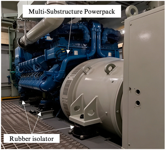
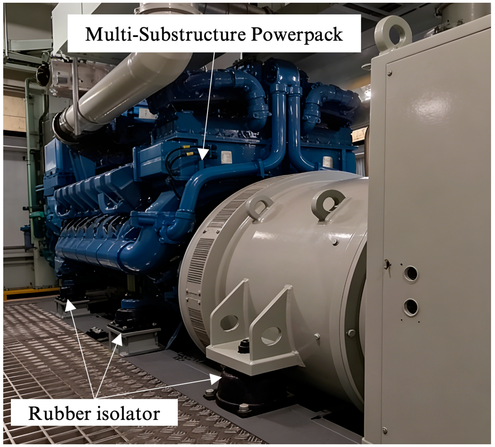
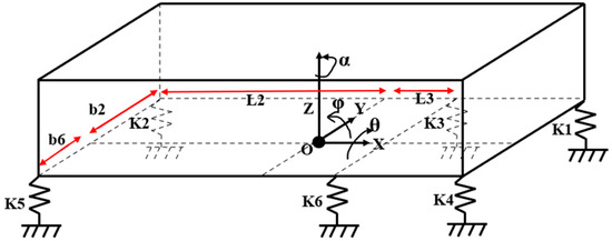
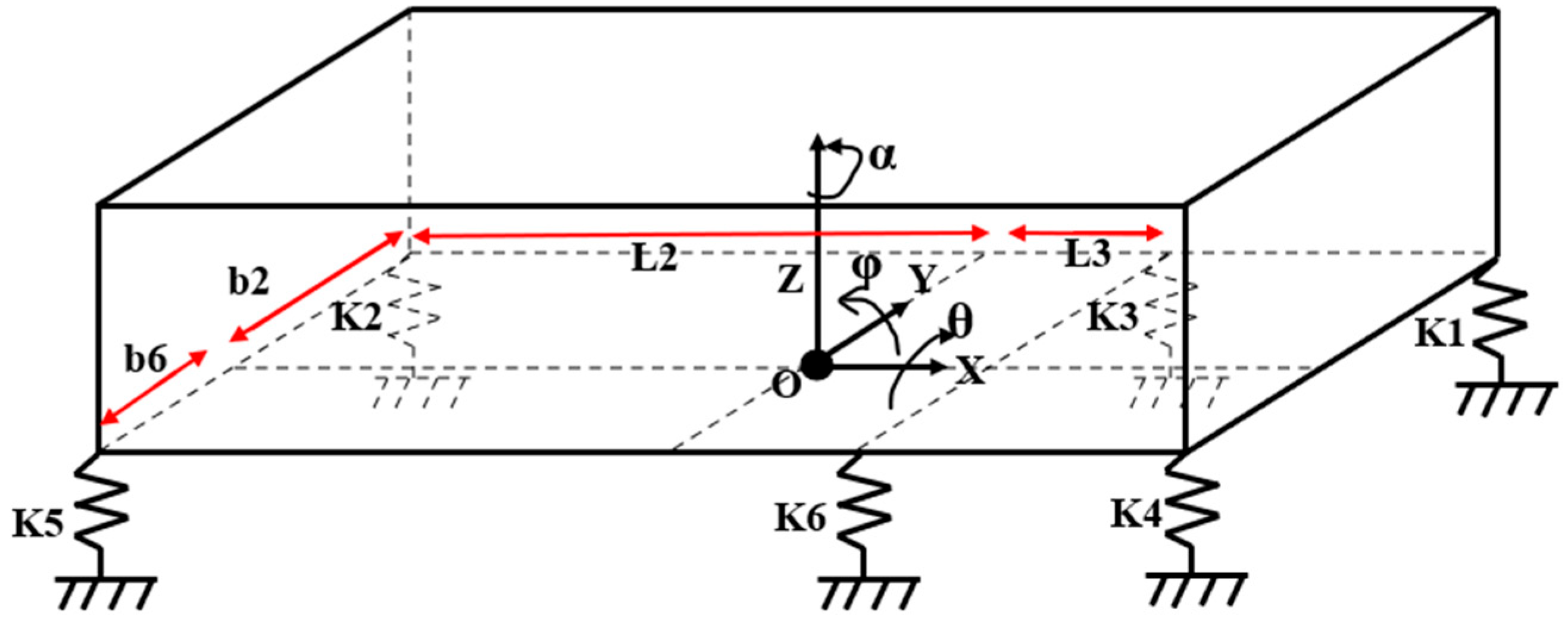
A multi-substructure power pack comprises multiple components, such as diesel generator sets and cooling systems, in a single framework (Figure 1). This power pack is elastically connected to the chassis of the vehicle at six points. Assuming the vehicle body to be a rigid foundation and the diesel generator set M to be a rigid body, the dynamics model of the single-layer isolation system for the power pack can be simplified, as shown in Figure 2.
Figure 1.
Structure of multi-substructure power pack.
Figure 2.
Simplified mechanical model of single-layer isolation system for a power pack.
The power pack has 6 degrees of freedom, and its motion differential equations are as follows:
In these equations, M, K, and C represent the mass matrix, stiffness matrix, and damping matrix of the isolation system, respectively. x, y, z, θ, φ, and α denote the displacements of the rigid body along the reference coordinate system (x, y, z, θ, φ, α); and Fx, Fy, Fz, Mx, My, and Mz represent the forces (or torques) exerted on the rigid body along the reference coordinate system (x, y, z, θ, φ, α).
The damping matrix is related to the stiffness matrix and the excitation frequency, and can be expressed according to the following formula:
where η is the damping factor and ω is the excitation frequency. In this study, the damping factor η was set to 0.1, which was determined based on the inherent material properties of the natural rubber isolators employed in the power pack system.
2.2. Stiffness Design of the Power Pack Vibration Isolator
The power pack of the vehicle is connected to the chassis via six wedge-shaped vibration isolators with known positions, coordinates, and initial static stiffness, as illustrated in Figure 1. A mechanical analysis was conducted for each isolator to establish its static equilibrium equation based on Hooke’s Law:
where is the reaction force of the i-th vibration isolator under the power pack; is the static deflection of the power pack center of mass; is the lateral coordinate of the i-th isolator in the local coordinate system; is the longitudinal coordinate of the i-th isolator in the local coordinate system; and are the tilt angles of the power pack around its center of mass in the x-axis and y-axis directions, respectively; and is the initial prescribed static stiffness of the i-th isolator.
For the power pack, conducting a force equilibrium analysis based on static principles yields the following set of equations for the static forces of the equipment mounted underneath the vehicle:
where is the mass of the power pack and = 9.81 m/s2 is the acceleration due to gravity.
Substituting each vibration isolator reaction force into (6), according to the initial prescribed static stiffness of each isolator, the equation can be solved for , , and . Subsequently, corrections are made to isolators with inconsistent static deflections to ensure that the power pack remains horizontal. The initial state variables , , and obtained from solving Equation (6) are substituted back into Equation (5) to determine each isolator’s reaction force . Based on the natural frequencies of the vehicle-mounted equipment and the permissible range of isolator static deflections, the corrected static deflection of the isolators can be determined:
where is the dynamic-to-static stiffness ratio of the isolator, and is the natural frequency of the power pack.
Revisiting the mechanical analysis for each isolator, we established the static equilibrium equation for each isolator based on Hooke’s Law:
where , and represent the optimized roll and pitch of the vehicle-mounted equipment after adjustment, and denotes the designed static stiffness of the i-th isolator. The initial natural frequency was set at 8 Hz based on the longitudinal symmetry characteristics of the power pack, with its triaxial stiffness design as follows: 5390 N/mm for Kx1/Kz1, 1617 N/mm for Ky1, 6440 N/mm for Kx2/Kz2, 1932 N/mm for Ky2, 5880 N/mm for Kx3/Kz3, and 1764 N/mm for Ky3.
3. Establishment and Analysis of Finite Element Models
3.1. Model Establishment and Modal Analysis
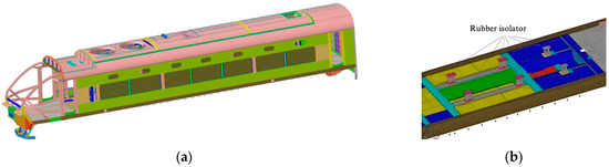
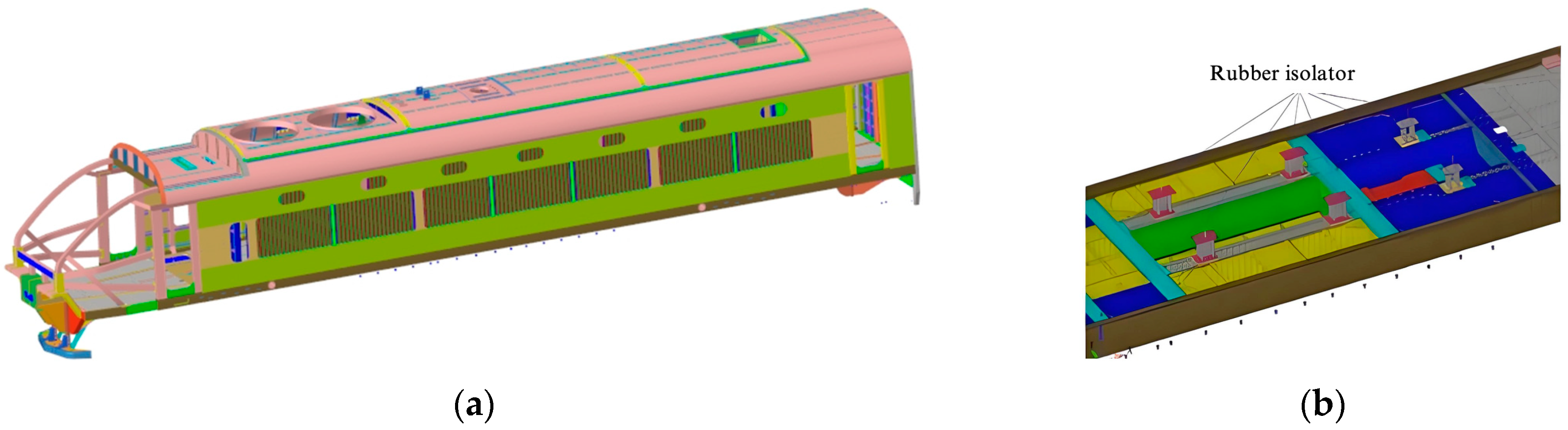
First, the three-dimensional structural modeling of the vehicle body was conducted. The model of the vehicle body primarily included the roof, body, underframe, driver cab section, and other undercarriage equipment such as the power pack. Subsequently, these components were discretized and meshed using a multi-zone meshing approach. The model comprised a total of 1,406,933 mesh elements and 1,429,494 mesh nodes (Figure 3a). Due to the complexity of the power pack structure and its various modes of motion, it was simplified to a lumped mass model connected to the vehicle body via six isolators (Figure 3b). The mass of the power pack was 14,050 kg.
Figure 3.
(a) The refined finite element model of the vehicle body including the power pack; (b) rubber isolator.
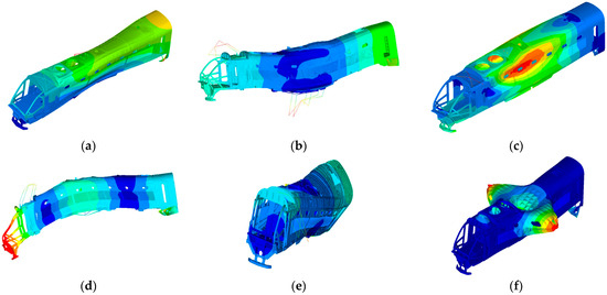
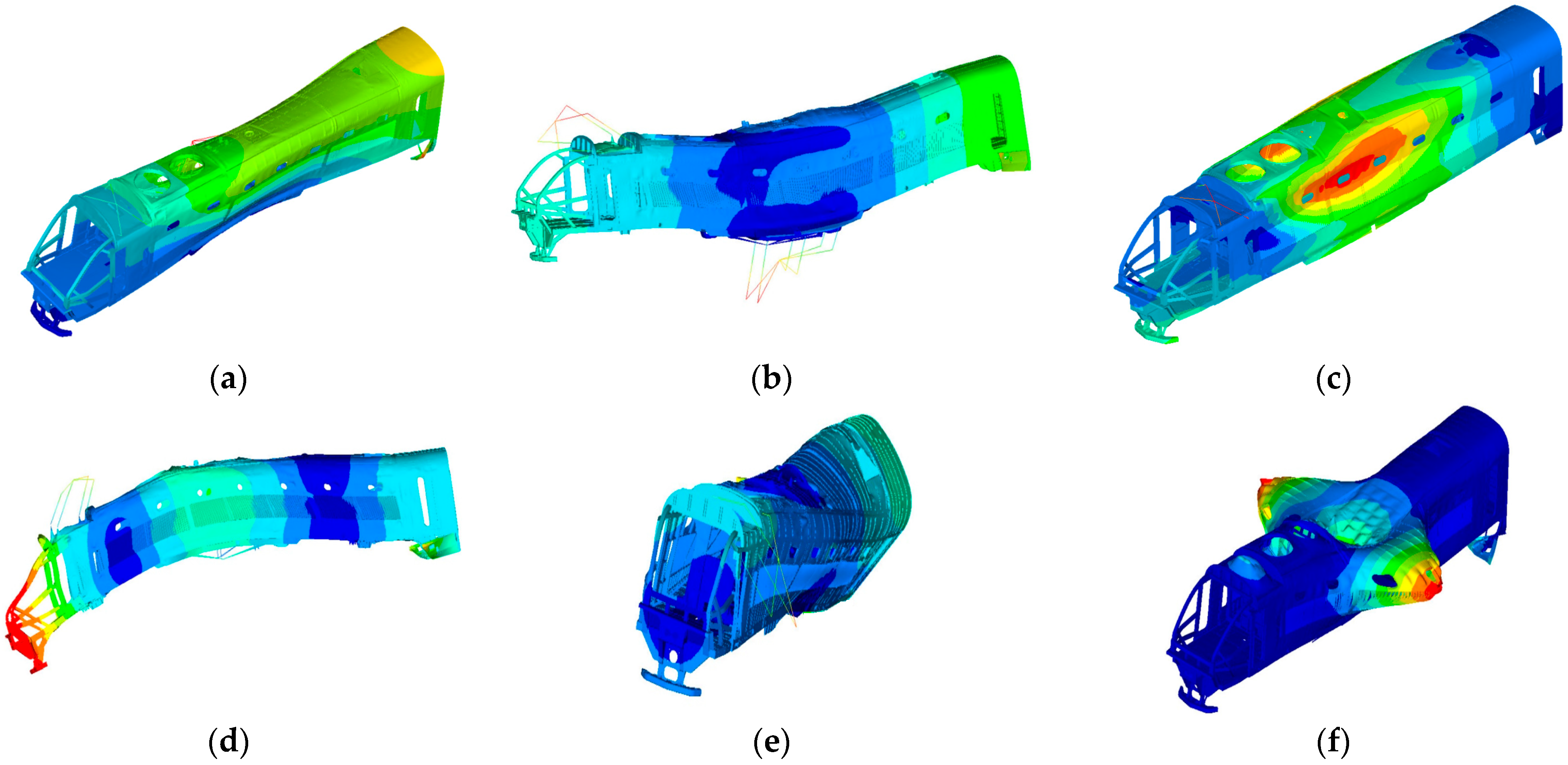
Modal analysis was performed to ascertain the inherent vibration characteristics of the vehicle body [8], including mode frequencies and shapes. Simultaneously, the analysis validated the accuracy of the established model. The first six mode shapes of the vehicle body are illustrated in Figure 4a–f, along with their modal frequencies. The modal frequencies obtained from the analysis closely match the experimental modal frequencies (Table 1), highlighting the accuracy of the established model.
Figure 4.
Diagrams of modal shapes: (a) diamond mode; (b) 1st-order vertical bending in-phase with power pack bouncing; (c) 1st-order lateral bending; (d) 1st-order vertical bending out-of-phase with power pack bouncing; (e) torsional mode; (f) breathing mode.
Table 1.
Variable design.
3.2. Analysis of Vehicle Vibration Characteristics Under Power Pack Excitation
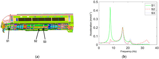
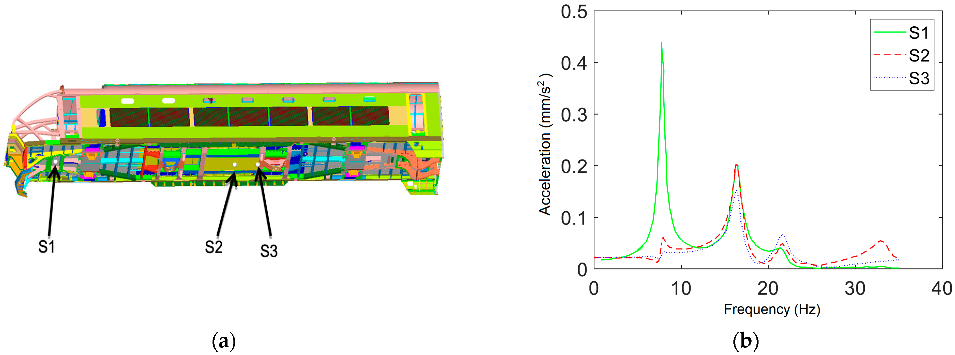
The diesel engine in this study operates at an idle speed of 600 rpm and normal operational speeds of 900–1800 rpm. The excitation forces during idle and normal operation are detailed in Appendix A. When analyzing the vehicle vibration characteristics under power pack excitation, specific points of interest on the vehicle were selected for computational study, such as the center of the driver cab (S1), the center of the car body (S2), and the floor directly beneath the power pack (S3) (Figure 5a). Modal analysis was used to calculate the response accelerations at these reference points after applying power pack excitation. The frequency response curves (Figure 5b) indicate that all three reference points exhibited a primary peak frequency around 7.8 Hz. Given that the vehicle’s second mode natural frequency is 7.8 Hz, resonance occurs when the excitation frequency matches this value, resulting in enhanced vibration amplitudes. Notably, point S1 showed higher vibration amplitudes compared to the other points, which was attributed to the vehicle’s second mode shape being a first vertical bending mode, where the vibration amplitudes at the sides of the vehicle are greater than those at the center.
Figure 5.
(a) Schematic diagram of reference point locations; (b) frequency response curves of reference points.
4. Multi-Objective Optimization of Power Pack Vibration Isolation Systems
4.1. Optimization Targets
During actual operation, the excessive vibrations in the driver cabin stem from the power pack being excessively excited. To address this practical issue, this section focuses on optimizing the parameters of the power pack vibration isolation system starting from a single vibration transmission path from the power pack to the vehicle body. Transmission efficiency is a critical metric for evaluating isolation performance, where force transmission efficiency is defined as the ratio of transmitted force to excitation force:
where is the amplitude of the response reactive force, and is the amplitude of the unit excitation force.
Three reference points of force transmission efficiency were used as the optimization criteria, with a higher transmission efficiency indicating poorer vibration isolation. To prevent scenarios where reducing vibrations in the driver cabin increases vibrations at other points on the vehicle body, a multi-objective optimization approach was designed:
where X is the variable, (, ) denotes the force transmission rate between the original stiffness points S2 and S3, and (A0, An) indicates the minimum and maximum values of the constrained variable.
4.2. Design Variables
The stiffness parameters of each shock absorber in a single-layer vibration isolation system exert a critical influence on the damping effect. Hence, it is imperative to choose appropriate design variables to optimize the results. In this study, we used the three-directional stiffness of the shock absorber as the design variables (Table 2). By seeking both the minimum and maximum values of the objective function, we strove to achieve superior vibration isolation performance for the system.
Table 2.
Variable design.
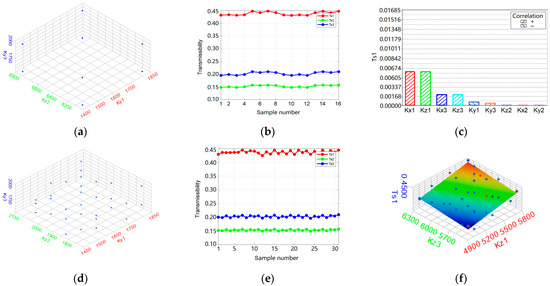
When designing a power pack isolation system, consideration must be given to 18 design variables encompassing the three-directional stiffness of the six isolators, resulting in a significant computational workload. Therefore, it is essential to perform sensitivity analysis on these design variables to eliminate the ones that do not contribute to the optimization objectives and enhance computational efficiency. Utilizing a fractional factorial design, variables with substantial impacts on the optimization metrics were identified (Figure 6a). Irregular fluctuations in transmission rates among three reference points within the sampled points were observed (Figure 6b). Pareto charts were employed to visually analyze the degree of influence of each factor on the force transmission rates at various points (Figure 6c). Notably, variable Kx1 exhibited the most significant impact on transmission rates at three points, followed by Kx3 and Ky1, while the influence of the other variables on transmission rates were largely negligible.
Figure 6.
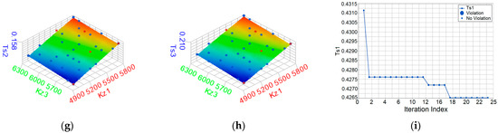
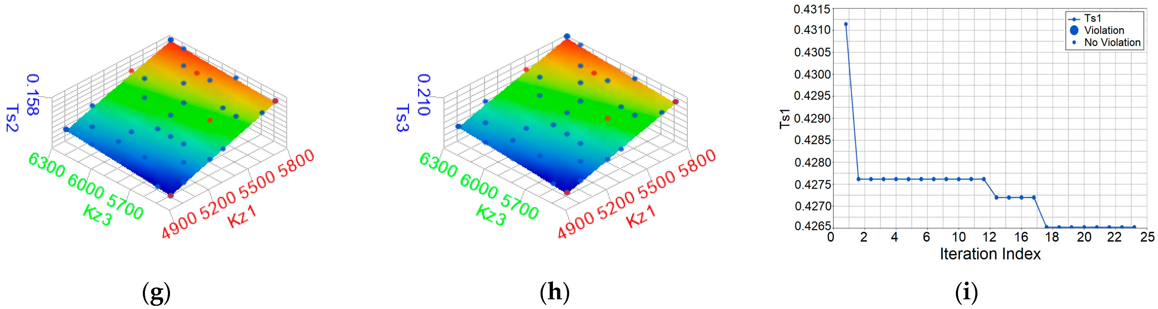
Multi-objective optimization of power pack vibration isolation system: (a) distribution projections of Kx2, Ky1, and Ky3 during initial selection; (b) sampling results during initial selection; (c) Ts1 Pareto chart; (d) distribution projections of Ky1, Ky2, and Ky3 during final selection; (e) sampling results during final selection; (f) Ts1 response surface; (g) Ts2 response surface; (h) Ts3 response surface; (i) variation in force transmissibility.
4.3. Multi-Objective Optimization Based on Global Response Surface Method
Using the Hammersley method for sampling ensures an even distribution of sampling points in the data space (Figure 6d); the simulation results were computed based on these samples (Figure 6e). Using the collected dataset, the Maximum Likelihood Estimation (MLSM) and LSR methods were employed to fit response surfaces for the maximum force transmission rates at three points (Figure 6f–h).
Here, denotes the predicted values and denotes the actual values. The fitting results are shown in Table 3, which demonstrates the high reliability of the fit.
Table 3.
Fitting results.
Using the GRSM algorithm for optimization, the objective was achieved after 17 iterations (Figure 6i), with a central floor force transmission rate of 32.65% in the driver cabin. After iterative calculations, the optimized stiffness values for each rubber isolator at the minimum objective function were as follows: 5090 N/mm (Kx1/Kz1), 1517 N/mm (Ky1), 6440 N/mm (Kx2/Kz2), 1932 N/mm (Ky2), 5480 N/mm (Kx3/Kz3), and 1764 N/mm (Ky3).
4.4. Simulation Verification
Using the finite element model to simulate and verify the results obtained from fitting and iterative optimization, the maximum force transmission rates at three points before and after optimization were determined (Table 4). It is evident that after optimization, the predicted force transmission rates closely match the simulated ones, demonstrating the validity of the optimization predictions. Additionally, the force transmission rate in the driver cabin was enhanced by 11.6%, with no increase in transmission rates at other points, meeting the optimization criteria.
Table 4.
Change in maximum force transmission rates at three points.
5. Test Verification
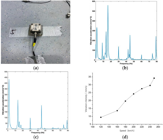
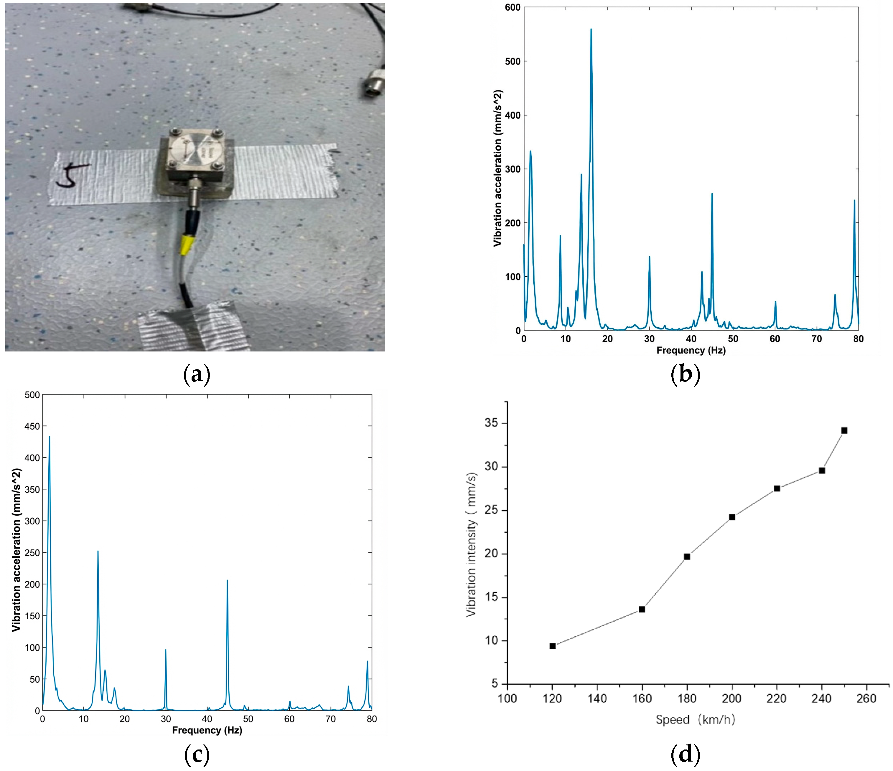
In the previous experiments, optimization design and simulation verification of the isolation system under single excitation (power pack excitation) were conducted. However, in actual operation, wheel–rail excitations also significantly affect cabin vibrations. Therefore, it is necessary to verify whether the optimized isolation system meets isolation requirements under coupled excitations. Operational line tests were conducted on a high-speed ballast track at speeds ranging from 120 to 200 km/h (Figure 7a). PCB ICP-type accelerometers were installed on the power pack, the interior floor, and the carbody underframe above the air springs to measure triaxial vibration accelerations (Figure 7b,c) and vibration intensity on the cabin floor (Figure 7d). Data were acquired at a sampling frequency of 1024 Hz and processed using a 0.5–80 Hz band-pass filter, in accordance with ISO 2631 standards [5]. Finally, the vibration comfort [20] in the cabin at different speeds was evaluated, and the corresponding comfort indices were measured to be 2.086, 2.304, and 2.487. The results indicate that all parameters meet the relevant standards, demonstrating the effectiveness of this isolation design method in enhancing the isolation efficiency of the power pack isolation system, indicating that this method possesses significant practical value.
Figure 7.
Test verification: (a) accelerometer; test results at speeds of (b) 200 km/h and (c) 240 km/h; (d) vibration intensity at the cabin floor.
6. Conclusions
A dynamic model of a single-layer isolation system for power packs was established. Based on vibration isolation theory and static load-bearing requirements, the optimal stiffness parameters of the isolation system were determined.
A refined finite element model of the vehicle body integrated with the power pack was developed. Modal analysis was conducted to extract the first six elastic modal frequencies and corresponding mode shapes of the vehicle body. Harmonic response analysis was then performed to characterize the vibration behavior of the vehicle under power pack excitation. The results show that resonant peaks appeared at frequencies of 7.8, 16.4, and 21.6 Hz in the driver’s cabin, with the 7.8 Hz peak being the most prominent. Therefore, targeted measures to suppress excitation frequencies around 7.8 Hz are recommended.
The triaxial stiffness of the isolation device was optimized, focusing on minimizing the maximum force transmission rate at the vehicle reference point. Multi-objective optimization was implemented using the global response surface methodology to determine the optimal stiffness parameters. The accuracy of the optimization predictions was verified via finite element simulations.
Field tests were carried out on the operational line under different working conditions. The vibration intensities of the power pack and the comfort indices of the driver’s cabin floor were calculated for each condition. The test results indicate that all parameters satisfy the requirements of the relevant standards, demonstrating that the proposed isolation design method can effectively improve the vibration isolation performance of power pack systems and thus possesses considerable practical engineering value.
Author Contributions
W.S.: Conceptualization, Methodology, Visualization, Experiments, Writing—Original Draft. D.G.: Experiments, Investigation, Writing—Review & Editing. All authors have read and agreed to the published version of the manuscript.
Funding
This research was funded by the National Natural Science Foundation of China (Grant Number 52375115), Shanghai Leading Talent Program of Eastern Talent Plan (Grant No. QNKJ2025010), State Key Laboratory of High-speed Maglev Transportation Technology (SKLM-SFCF-2025-007) and the China CRRC Corporation Limited Science and Technology Research and Development Program Project (2025CYB413).
Data Availability Statement
No new data were created or analyzed in this study.
Conflicts of Interest
Author W.S. was employed by CRRC Qingdao Sifang Co., Ltd. The remaining authors declare that the research was conducted in the absence of any commercial or financial relationships that could be construed as a potential conflict of interest.
Appendix A. The Excitation Forces During Idle and Normal Operation
| Speed | Centrifugal Inertial Force /N | Speed | Centrifugal Inertial Force /N |
| Idling | 82 | 1400 | 115 |
| 1000 | 82 | 1500 | 123 |
| 1100 | 90 | 1600 | 131 |
| 1200 | 98 | 1700 | 139 |
| 1300 | 107 | 1800 | 148 |
References
- Song, S.; Hua, C.; Huang, Y.; Cai, D.; Dong, D.; Yan, B. Semi-active fuzzy control of a powerpack with magneto-rheological dampers at full operating conditions. J. Vib. Control 2024, 30, 5418–5430. [Google Scholar] [CrossRef] [Scilit]
- Dumitriu, M. On-line running tests for validating the numerical simulations of the vertical dynamic behavior in railway vehicles. Appl. Mech. Mater. 2014, 657, 609–613. [Google Scholar] [CrossRef] [Scilit]
- Mazilu, T.; Dumitriu, M.; Sorohan, S.; Gheți, M.A.; Apostol, I.I. Testing the effectiveness of the anti-bending bar system to reduce the vertical bending vibrations of the railway vehicle carbody using an experimental scale demonstrator. Appl. Sci. 2024, 14, 4687. [Google Scholar] [CrossRef] [Scilit]
- Men, Z.; Gong, D.; Zhou, K.; Chen, Y.; Zhou, J. Unsupervised domain adaptation method for bearing fault diagnosis assisted by twin data under extreme sample scarcity. Mech. Syst. Signal Process. 2025, 239, 113359. [Google Scholar] [CrossRef] [Scilit]
- ISO 2631-1:2010; Mechanical Vibration and Shock—Evaluation of Human Exposure to Whole-Body Vibration—Part 1: General Requirements. International Organization for Standardization: Geneva, Switzerland, 2010.
- Jing, J.H.; Li, C.G.; Peng, B.; Li, S.J.; Wen, Z.F.; Wu, X.W. Fatigue failure analysis and life prediction of welded aluminum alloy frames suspended from high-speed EMU. Eng. Fail. Anal. 2024, 159, 108024. [Google Scholar] [CrossRef] [Scilit]
- Dumitriu, M. Numerical study of the influence of suspended equipment on ride comfort in high-speed railway vehicles. Sci. Iran. 2020, 27, 1897–1915. [Google Scholar] [CrossRef] [Scilit]
- Minasyan, M.A.; Minasyan, A.M. The method of experimental verification of the hypothesis about the possibility of reducing the vibration activity of diesel generators using rope dampers “MAMSAR” with zero stiffness. Mar. Intellect. Technol. 2024, 4, 161–166. [Google Scholar] [CrossRef] [Scilit]
- Boychuk, I.P.; Grinek, A.V.; Martyushev, N.V.; Klyuev, R.V.; Malozyomov, B.V.; Tynchenko, V.S.; Kukartsev, V.A.; Tynchenko, Y.A.; Kondratiev, S.I. A methodological approach to the simulation of a ship’s electric power system. Energies 2023, 16, 8101. [Google Scholar] [CrossRef] [Scilit]
- Li, B.; Yang, H. Design of active vibration reduction system for intelligent ship mechanical equipment. J. Coast. Res. 2020, 99, 235–237. [Google Scholar] [CrossRef] [Scilit]
- Yang, T.; Wu, L.; Liu, Z.; Liu, S. Active vibration isolation of a diesel generator in a small marine vessel: An experimental study. Appl. Sci. 2020, 10, 3025. [Google Scholar] [CrossRef] [Scilit]
- Chen, M.; Ouyang, H.; Liu, S. Partial frequency assignment for torsional vibration control of complex marine propulsion shafting systems. Appl. Sci. 2020, 10, 147. [Google Scholar] [CrossRef] [Scilit]
- Wang, Z.G.; Gong, D. A survey on countermeasures of railway vehicle stability decrease caused by the evolution of hollow-worn wheels. J. Vib. Control 2025, 31, 864–877. [Google Scholar] [CrossRef] [Scilit]
- Zhai, W.; Wang, K.; Cai, C. Fundamentals of Vehicle–Track Coupled Dynamics. Veh. Syst. Dyn. 2009, 47, 1349–1376. [Google Scholar] [CrossRef] [Scilit]
- Liu, P.F.; Wei, K.; Wang, K.Y.; Feng, Q.B. Testing of modified primary stiffness for heavy-haul locomotives operating on sharper-radius curves. Proc. Inst. Mech. Eng. Part K J. Multi-Body Dyn. 2019, 233, 531–548. [Google Scholar] [CrossRef] [Scilit]
- Huang, C.H.; Zeng, J.; Luo, G.B.; Shi, H.L. Numerical and experimental studies on the car body flexible vibration reduction due to the effect of car body-mounted equipment. Proc. Inst. Mech. Eng. Part F J. Rail Rapid Transit 2018, 232, 103–120. [Google Scholar] [CrossRef] [Scilit]
- Deng, X.; Gong, D.; Zhou, J. Effect of rubber ageing on underchassis equipment-body coupling vibration in high-speed trains. J. Vib. Control, 2025; Advance online publication. [CrossRef] [Scilit]
- Cho, T.; Song, M.K.; Lee, D.H. Reliability analysis for the uncertainties in vehicle and high-speed railway bridge system based on an improved response surface method for nonlinear limit states. Nonlinear Dyn. 2010, 59, 1–17. [Google Scholar] [CrossRef] [Scilit]
- Xie, K.Z.; Liu, B.W.; Dai, W.W.; Chen, S.L.; Wang, X.M. Performance analysis of short-span simply supported bridges for heavy-haul railways with a novel prefabricated strengthening structure. Buildings 2023, 13, 876. [Google Scholar] [CrossRef] [Scilit]
- GB/T 5599-2019; Code for Testing of Dynamic Performance for Rolling Stock. Standards Press of China: Beijing, China, 2019.


Disclaimer/Publisher’s Note: The statements, opinions and data contained in all publications are solely those of the individual author(s) and contributor(s) and not of MDPI and/or the editor(s). MDPI and/or the editor(s) disclaim responsibility for any injury to people or property resulting from any ideas, methods, instructions or products referred to in the content. |
© 2026 by the authors. Licensee MDPI, Basel, Switzerland. This article is an open access article distributed under the terms and conditions of the Creative Commons Attribution (CC BY) license.