


Abstract
With the rapid development of rail transit, how to power low-energy monitoring systems for the vast and complex infrastructure in the rail transit system is becoming an urgent problem. To achieve green and intelligent rail transit infrastructure while ensuring long-term operational safety, harvesting vibration energy from tracks to power wireless sensor networks has become a research hotspot. This paper designs a track vibration energy harvester based on a broadband magnetic levitation structure. First, a dynamic model of the harvester is established, and the corresponding dynamic equations, energy–velocity relationship, and system transfer function are derived. Also, by simulating electromagnetic interactions, the distribution pattern of magnetic density inside the energy harvester is revealed. Next, the response characteristics of the energy harvester are analyzed under single-frequency and multi-frequency excitation conditions. Using the Runge-Kutta algorithm for computational analysis, the optimal structural parameters of the energy harvester are designed. Finally, a magnetic levitation energy harvester prototype is constructed. Experimental validation confirmed the feasibility of the energy harvester and its adaptability to low-frequency vibration environments.
1. Introduction
With the rapid development of Chinese society and technology, public transportation demands continue to grow, leading to the ongoing expansion of rail transit network scales and increased operational maintenance pressure for trains. Consequently, enhancing train operational safety and efficiency has become a critical issue in rail transit development, giving rise to digital and intelligent operation and maintenance solutions based on track monitoring and early warning systems. As the initial component, sensors are responsible for collecting target data and communicating to data processing systems. Therefore, sensors are critical components while the accuracy, integrity and reliability of data directly impact the decision-making of the monitoring and early warning system.
However, the current battery-powered mode of sensor operation presents multiple drawbacks. Batteries require periodic replacement or charging, and maintaining a large number of sensor nodes consumes significant human and time resources, reducing system operational efficiency [1,2]. Batteries also pose environmental pollution concerns, because their energy sources often come from thermal power generation, falling short in terms of green and low-carbon sustainability [3]. To enhance the operational and maintenance efficiency of electrical equipment while responding to national calls for energy transition, scholars have conducted extensive research on environmental energy harvesting such as solar energy, wind energy and geothermal energy [4,5,6,7,8]. Among these efforts, harvesting energy from environmental vibrations, especially from the inherent vibration environment of rail transit has emerged as a research focus [9,10].
Vibration energy harvesters are mainly divided into piezoelectric, electromagnetic, and frictional types. Although piezoelectric harvesters provide high output voltage, they often face challenges in achieving high output power. In contrast, electromagnetic energy harvesters have the characteristics of low impedance and high current output, making them particularly suitable for powering sensors in railway environments. Therefore, this article mainly focuses on the electromagnetic vibration energy harvester.
Optimization of the mechanical structure is critical for enhancing energy harvesting performance [11,12]. However, traditional linear spring-based structures face inherent limitations, such as fatigue failure under long-term high-intensity impacts and narrow resonance bandwidth [13]. To overcome these drawbacks, introducing nonlinear dynamics to broaden the frequency bandwidth has become a frontier research direction.
In the field of vibration nonlinear energy harvesting, groundbreaking work has established a rigorous theoretical framework for broadband enhancement. Cottone et al. [14] demonstrated the superior performance of a bistable oscillator using a magnetically coupled piezoelectric inverted pendulum and derived control equations that clearly explain stochastic dynamics and potential well transitions. Similarly, Erturk and Inman [15] conducted a comprehensive analysis of the electromechanical coupling in a bistable Duffing oscillator used for broadband power generation. Although these studies provide fundamental physical foundations for fully coupled electromechanical dynamics, engineering applications often require simplified models for rapid prototyping and structural parameter iteration.
Building upon these nonlinear theoretical foundations, magnetic levitation structures have emerged as a promising engineering solution to realize nonlinear characteristics [16]. By utilizing magnetic restoring forces to replace or partially replace physical springs, these designs not only generate the desired nonlinear stiffness for bandwidth enhancement, but also eliminate mechanical friction and fatigue issues common in rail environments. Along this technological route, researchers have developed various magnetic levitation energy harvesters.
In 2016, Wang et al. designed a two-degree-of-freedom magnetic levitation vibration energy harvester featuring elastic coupling between a mass block and a forced vibration element [17]. Simulation results demonstrated four resonance peaks under external excitation, indicating that adding the mass block optimized both output power and energy harvesting bandwidth. Chen et al. designed a novel triangular three-degree-of-freedom structure. with vertically vibrating mass blocks at the vertices [18]. Displacement was converted to the horizontal direction via two light rods and a slider, achieving nonlinear coupling. This broadened the response frequency band while leveraging the lever mechanism to amplify the relative displacement and velocity between magnets and coils. The output voltage was effectively increased to 4.98 V—1.76 times that of traditional linear systems under equivalent input conditions. Liu et al. designed a horizontal electromagnetic energy harvester based on a Halbach permanent magnet array [19]. The permanent magnet is fixed to a hollow mass block mounted on a guide shaft, with spring couplings at both ends. This allows the permanent magnet to reciprocate along the guide shaft as a moving element, generating relative displacement with the coil stator to produce current. The permanent magnets employed Halbach magnetization to enhance magnetic field strength while facilitating lightweight design. The device ultimately generated a rectified voltage of approximately 5 V with an output power of 0.4 W. Zhang et al. designed an electromagnetic vibration energy harvester combining magnetic levitation and spring structures [20]. This design enables segmented responses across different frequency bands, broadening the operational bandwidth and improving the collector’s response to low frequencies. Consequently, it operates efficiently at excitation frequencies below 14 Hz. Holm et al. designed an electromagnetic energy harvester featuring a dumbbell-shaped dual-layer suspended magnet [21]. By modifying the suspended magnet structure, they reduced internal friction and increased the rate of magnetic flux change, achieving a maximum output of 1.04 mW under excitation conditions of 4–20 Hz and 3 mm amplitude. Gao et al. [22] leveraged the wide-band response characteristics of magnetic suspension oscillators to configure a track energy harvesting device. This device converts the output AC voltage into DC power, supplying lithium batteries to stably power a suite of sensors (including accelerometers, temperature sensors, humidity sensors, and infrared sensors). After collecting data, the sensors communicate with ZigBee coordination devices to transmit information to computers, enabling wireless communication via the ZigBee network. This energy harvester underwent field testing on a railway section in Chengdu. An oscilloscope connected to the magnetic levitation oscillator recorded the harvester’s response. By adjusting the number of coil turns, coil geometry and arrangement, magnetic flux density, and suspended magnet mass, an induced voltage output ranging from 2 V to 4 V was achieved. Yang et al. [23] has explored the use of frequency-dependent equivalent impedance analysis to optimize the vibration isolation and energy harvesting performance of vehicle suspension systems.
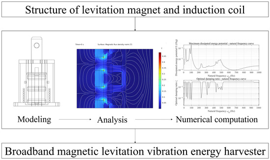
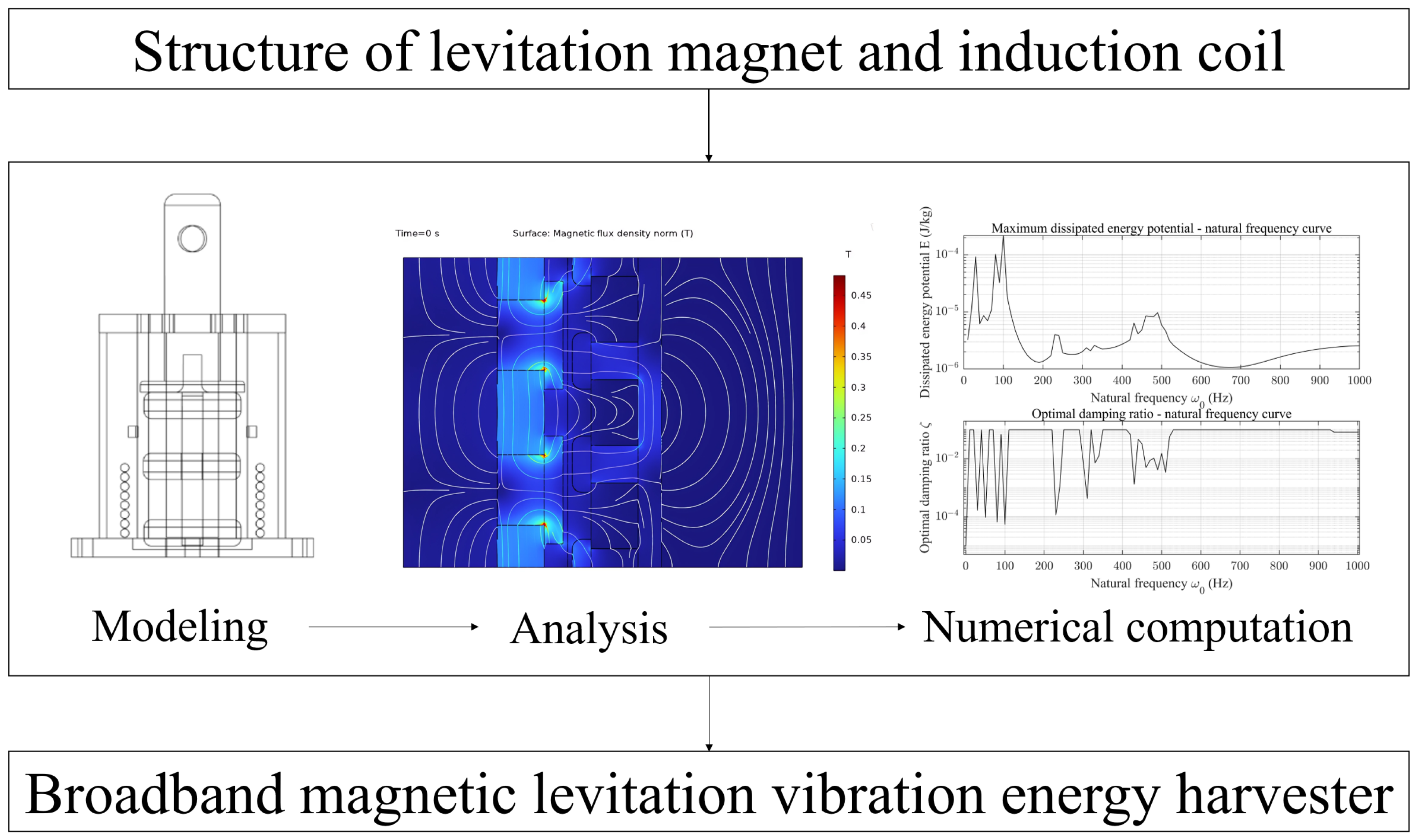
These studies have effectively enhanced the output power and response bandwidth of vibration energy harvesting systems. However, efforts of these studies usually cannot be directly applied to the environment of rail transit. The sensors within the track monitoring and early warning system face challenges due to their large number and the limited space along the track. Additionally, track vibrations exhibit greater amplitude and broader frequency bands than conventional environmental vibrations, sometimes with prominent dominant frequencies. Conventional vibration energy harvesting devices remain unsuitable for rail transit applications. To enhance the feasibility and adaptability of energy harvesters in track monitoring systems while maximizing harvesting performance, targeted design of harvester structure and frequency bandwidth is essential. Therefore, this paper presents a track vibration energy harvester based on a broadband single-degree-of-freedom magnetic levitation structure, specifically engineered for vibration energy harvesting in track environments with theoretical analysis and experimental validation. The research method of this article is shown in Figure 1.
Figure 1.
Research method of the electromagnetic vibration energy harvester.
The contributions in this paper are summarized as follows:
(1) Designed and fabricated a frequency-tunable vibration energy harvester suitable for installation in rail environments;
(2) Through dynamic analysis and simulation calculations, elucidated the fundamental principles and electromagnetic distribution patterns of the vibration energy harvester, achieving optimal structural parameter design;
(3) Conducted performance testing on the actual harvester unit, preliminarily validating its feasibility for sensor powering applications.
The arrangement of the article sections is as follows: Section 1 discusses the research background and significance of rail vibration energy harvesters, along with the current state of research, laying the foundation for subsequent content. Section 2 explains the fundamental operating principles of the energy harvester and designs its structure tailored for the trackside environment; Section 3 establishes a dynamic model of the energy harvester and simulates electromagnetic interactions to reveal the magnetic flux density distribution patterns within it; Section 4 performs numerical calculations based on a MATLAB/Simulink (version R2024b) model and Runge-Kutta algorithm to compare the dynamic response of the harvester under different conditions and parameters, as well as to derive optimal structural parameters; Section 5 constructs a test platform, fabricates and tests the designed energy harvester’s output performance, and analyzes the results; Section 6 summarizes the research content and outlines future research directions.
2. Design of the Track Vibration Energy Harvester
The fundamental principle of electromagnetic energy harvesters is Faraday’s law of electromagnetic induction, which states that the magnitude of the induced electromotive force in a circuit is directly proportional to the rate of change of magnetic flux through that circuit. This relationship is expressed mathematically as shown in (1):
Based on Faraday’s law of electromagnetic induction, when a train passes through the energy harvester installation zone, the interaction between the wheels and rails induces vertical vibrations in the track. The suspended magnet of the energy harvester acts as a forced vibration element, with relative motion to the induction coil. This motion causes the coil to cut through the magnetic field lines, generating an induced electromotive force across the resistor terminals. Thus, the mechanical energy from track vibrations is converted into electrical energy.
The optimization approach for electromagnetic vibration energy harvesters in this section is as follows referring to the study by Gatti et al. [24]: First, necessary simplifications are made to the model of the electromagnetic vibration energy harvester with magnetic levitation coupling. This includes treating measured track vibration data directly as excitation input to the harvester system, disregarding energy losses during coupling between the harvester and track-related structures. Second, the counteraction of the energy harvester on track vibration upon excitation is neglected. This assumes a unidirectional force relationship between the track excitation source and the vibration energy harvester, where the harvester does not influence the track’s vibration characteristics.
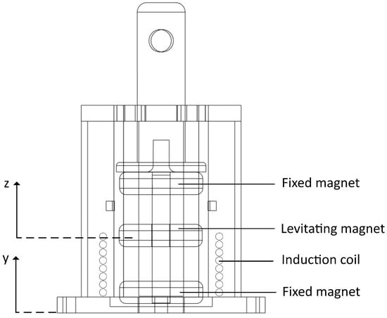
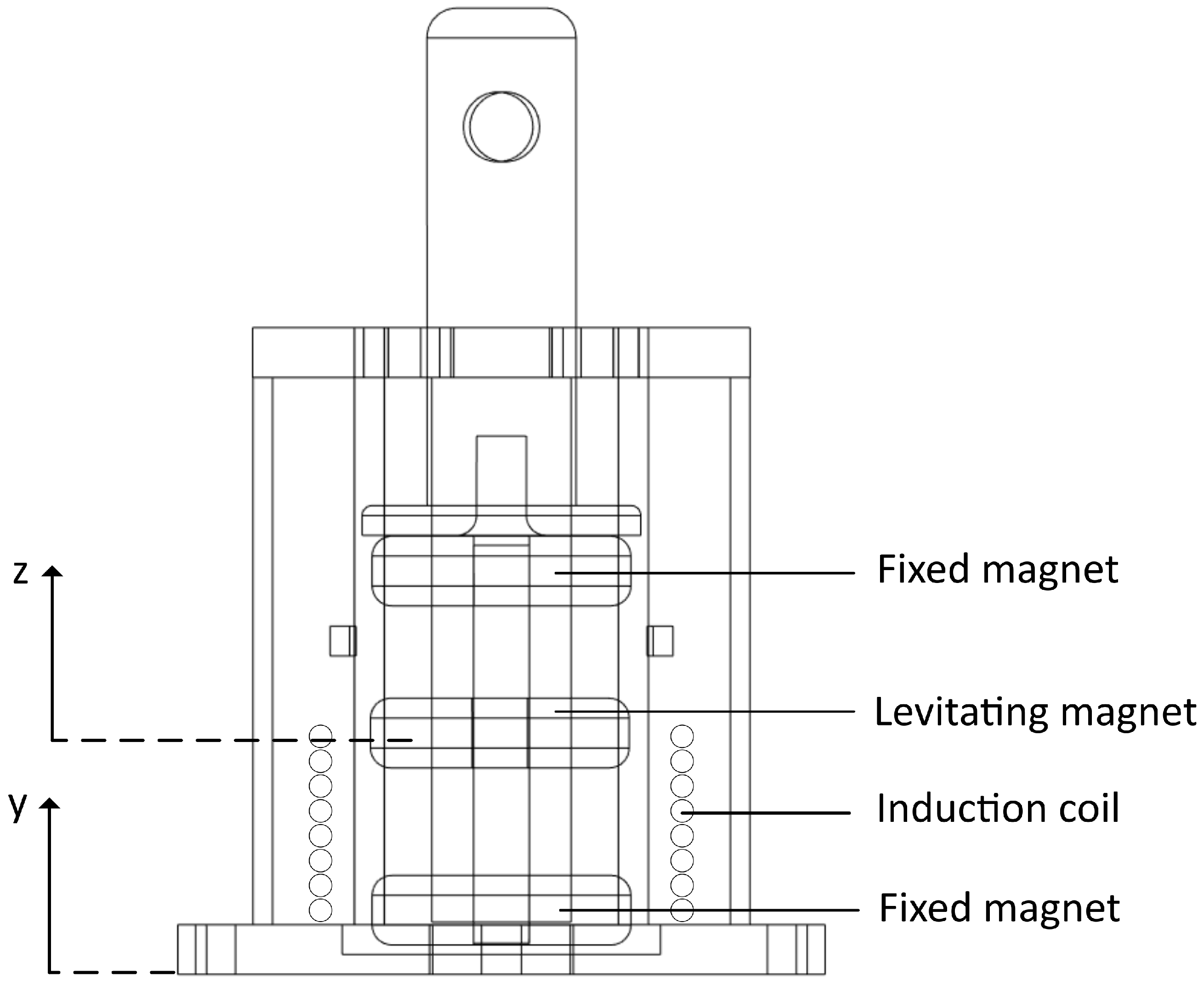
The classic structure of electromagnetic energy harvesters can be modeled as mass-spring-damper systems. To broaden the response frequency band of electromagnetic vibration energy harvesters, this paper adopts a magnetic levitation coupling design in the harvester structure. The simplified harvester structure is shown in Figure 2.
Figure 2.
Structure of the electromagnetic vibration energy harvester.
In its initial state, the electromagnetic vibration energy harvester is not subjected to external vibration excitation. The suspended magnet within the harvester remains stationary between the upper and lower fixed magnets. At this point, there is no relative velocity or displacement between the two degrees of freedom of the harvester system. Consequently, there is no change in magnetic flux within the induction coil, and no induced voltage or current is generated. When external excitation occurs, the fixed magnet connected to the energy harvester’s housing shifts first. The distance between this fixed magnet and the originally stationary suspended magnet changes. After that, the electromagnetic repulsive force exerted on the suspended magnet by the upper and lower fixed magnets also varies. This disrupts the equilibrium state, causing the harvester to enter an oscillatory state. The relative motion between the suspended magnet and the coil alters the magnetic flux through the coil, inducing both voltage and current.
3. Dynamics and Magnetic Flux Density Analysis of the Energy Harvester
3.1. Dynamics Analysis of the Energy Harvester
The magnetically levitated electromagnetic vibration energy harvester constitutes a nonlinear single-degree-of-freedom structure subjected to base excitation. Its fundamental dynamic equation is shown as follows:
In Equation (2), m denotes the mass of the suspended magnet. z denotes the relative displacement between the suspended magnet and the harvester housing, while and represent the first and second derivatives of z, corresponding to the relative velocity and relative acceleration. y indicates the displacement of the harvester housing, while and denote the velocity and acceleration of the housing, as well as the first and second derivatives of y. c denotes the total equivalent damping coefficient, which includes both the mechanical viscous damping (from structural friction and air resistance) and the electromechanical coupling damping (induced by the Lorentz force reaction from the harvesting circuit).
It is acknowledged that rigorous physical models, as established in [14,15], include a backward electromechanical coupling term in the equation of motion. However, in this simplified model, the backward electromechanical coupling is approximated as a linear viscous damping term c to facilitate parameter analysis.
represents the nonlinear magnetic levitation force acting on the suspended magnet, shown in Equation (3):
In Equation (3), and are the linear and nonlinear magnetic stiffness coefficients.
Following the modeling approach established by Gatti et al. [24], we define the objective function based on the energy dissipated by the equivalent damping. The total dissipated mechanical energy over a time period t is expressed as:
It is worth noting that this quantity E represents the theoretical upper limit of the potential for harvested energy. In the physical prototype, due to the conversion efficiency of sensors and circuit losses, the actual extracted electrical energy will be a small fraction of E.
Unlike linear systems, this nonlinear equation cannot be easily solved using standard transfer functions. Therefore, in Section 4.1, we employ a numerical simulation model to solve this equation and analyze the system’s dynamic response under various excitations. To visually observe the magnetic field density distribution within the harvester, the subsequent subsection will conduct a multi-physics simulation of the harvester system.
3.2. Magnetic Density Analysis of Energy Harvester
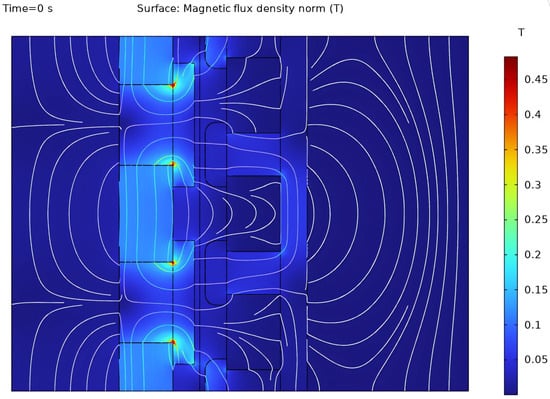
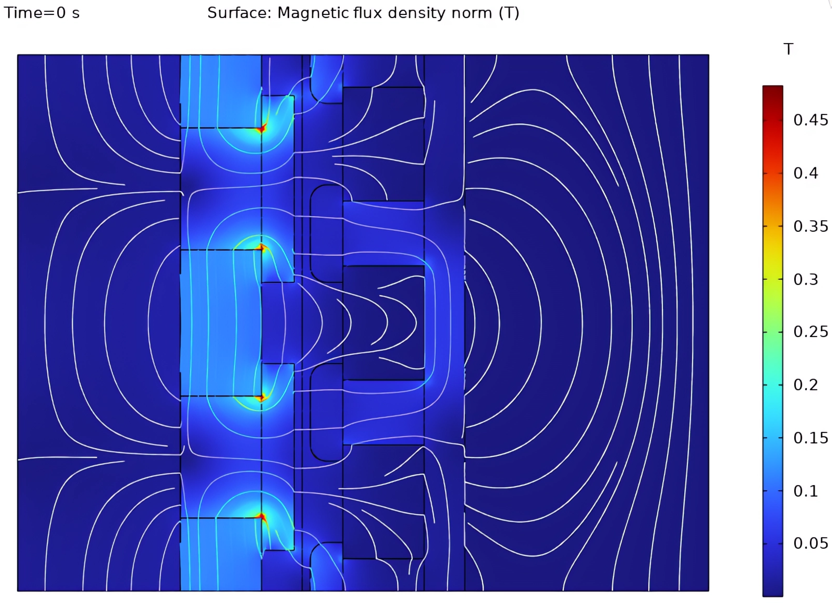
To visualize the fundamental electromagnetic mechanism, a conceptual finite element model was established in COMSOL Multiphysics (version 6.1). The simulation framework was developed with reference to the COMSOL Application Library model “Tubular Permanent Magnet Generator” (Application ID: 20381), with adjustments made to the magnetic structure, material properties, and excitation parameters to suit the specific needs of this study. This simulation utilized COMSOL’s “Magnetic Field” and “Moving Mesh” modules, configuring three permanent magnets and a set of coils. A sinusoidal relative motion was established between the magnets and coils. As shown in the magnetic flux density distribution contour plot in Figure 3, the magnetic induction intensity within the three magnets on the left is significantly stronger than in structures such as air gaps and coils. The magnetic induction intensity reaches its maximum value at the end points of the magnets closest to the coils. The magnetic induction intensity inside the coils is higher than in the surrounding space. This simulation serves to illustrate the physical principle of the magnetic circuit, and the specific geometric dimensions of the energy harvester are detailed in Section 5.
Figure 3.
Conceptual illustration of the magnetic flux density distribution in a repulsive magnetic structure.
4. Optimal Design of Structural Parameters for the Energy Harvester
4.1. Single-Frequency Excitation Response Analysis
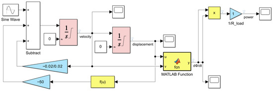
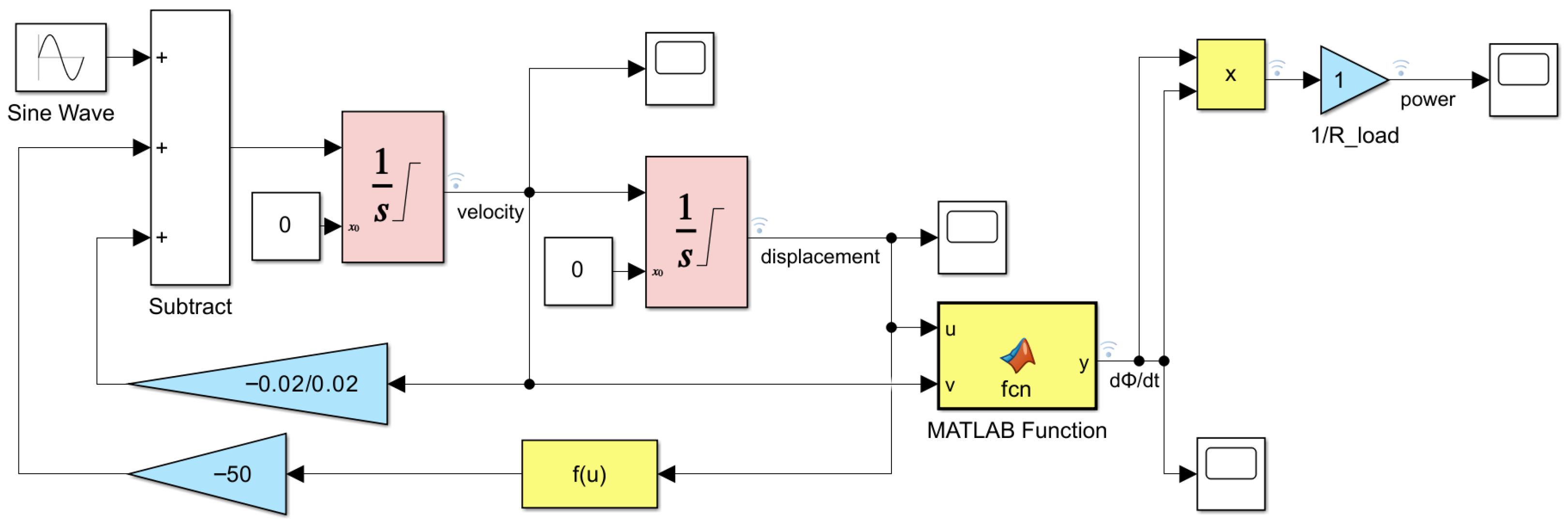
To analyze the dynamic response of the vibration energy harvester, this section establishes a MATLAB/Simulink model of the harvester. This model calculates and compares the dynamic response under different conditions and parameters. The electromagnetic vibration energy harvester model constructed on the MATLAB/Simulink platform based on the segmented nonlinear electromechanical coupling theory [25,26,27] is shown in Figure 4.
Figure 4.
Electromagnetic energy harvester model on Simulink.
The computational flow of this Simulink model is primarily divided into three parts: the first part is used to solve for excitation inputs, including external sinusoidal excitation signals and magnetic restoring forces; the second part is used to integrate the input acceleration variable, with two integration steps outputting relative velocity and relative displacement, respectively, and feeding them back to the input stage; the third part is used to calculate the rate of change of magnetic flux (induced electromotive force) and instantaneous output power.
The Sine Wave module is used to input sinusoidal excitation to the system; the Subtract module calculates the system’s comprehensive force conditions, including external excitation terms, damping terms, and magnetic repulsion terms; the Integrator Limited module integrates the acceleration values of the input excitation to obtain the system’s velocity and displacement; the Gain module introduces damping and magnetic repulsion term coefficients; the Fcn module calculates magnetic repulsion based on (3). To avoid numerical singularity when the displacement term in the denominator approaches zero, a small regularization parameter m is introduced into the denominator of the flux density function. This ensures the stability of the MATLAB Function block shown in Figure 4.
The Product module, serving as the integration stage, calculates the system output power according to (5). is the load resistance, assumed to be unity () for normalized power analysis in this numerical study.
This setup also enables exporting various physical quantities during system operation, allowing observation of their waveforms and changes, including input excitation acceleration, system velocity and displacement, rate of change of magnetic flux, and coil output power. Single-frequency excitation acceleration a set to 0.3 g, 0.5 g, and 1 g (equivalent to 2.94 m/s2 4.9 m/s2, and 9.8 m/s2), and the system damping values are 0.001 N/(m·s), 0.005 N/(m·s), 0.01 N/(m·s), 0.02 N/(m·s), and 0.05 N/(m·s), respectively. The frequency sweep range is 0.1 Hz to 100 Hz. A variable-step solver was employed during simulation to prevent significant distortion of the excitation signal, with a stop time set at 10 s.
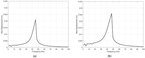
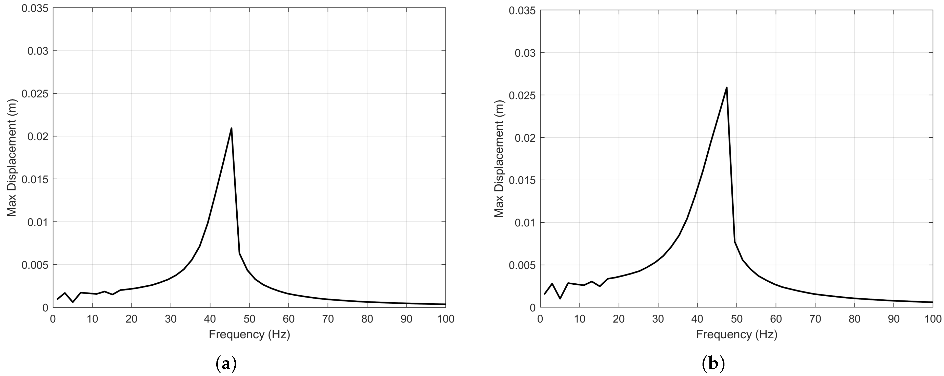
The relationship between the maximum system displacement obtained from nonlinear model simulations and the single-frequency excitation frequency for each parameter combination is shown in the following figures. In Figure 5a, the maximum displacement of the middle magnet occurs at approximately 44 Hz, with a peak displacement of about 0.021 m. In Figure 5b, the maximum displacement of the middle magnet occurs at approximately 48 Hz, with a peak displacement of about 0.026 m.
Figure 5.
(a) Displacement-frequency curve: a = 0.3 g, c = 0.02 N/(m/s). (b) Displacement-frequency curve: a = 0.5 g, c = 0.02 N/(m/s).
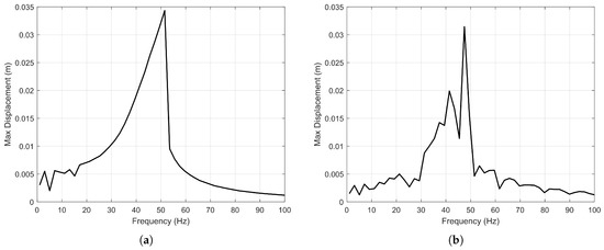
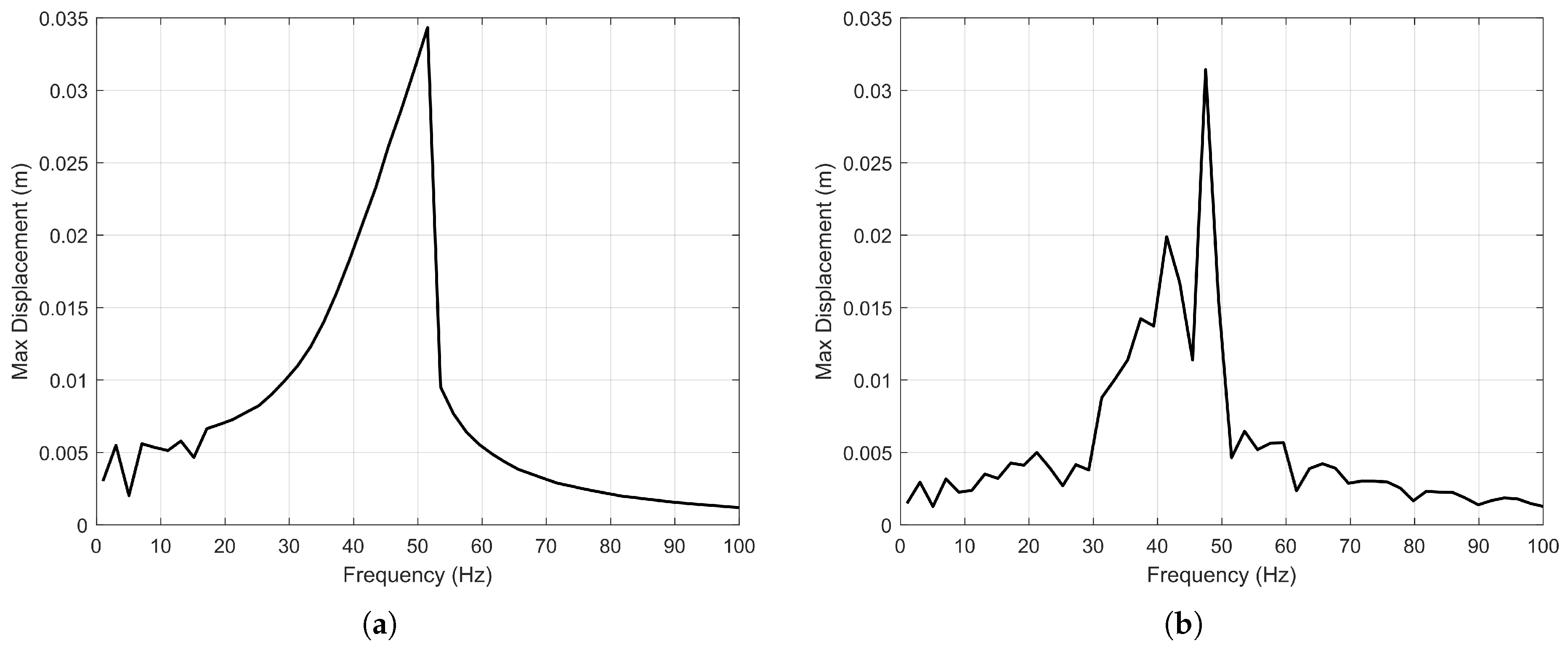
In Figure 6a, the maximum displacement of the middle magnet occurs at approximately 52 Hz, with a peak displacement of about 0.035 m; in Figure 6b, the maximum displacement of the middle magnet occurs at approximately 47 Hz, with a peak displacement of about 0.032 m.
Figure 6.
(a) Displacement-frequency curve: a = 1 g, c = 0.02 N/(m/s). (b) Displacement-frequency curve: a = 0.5 g, c = 0.001 N/(m/s).
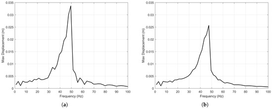
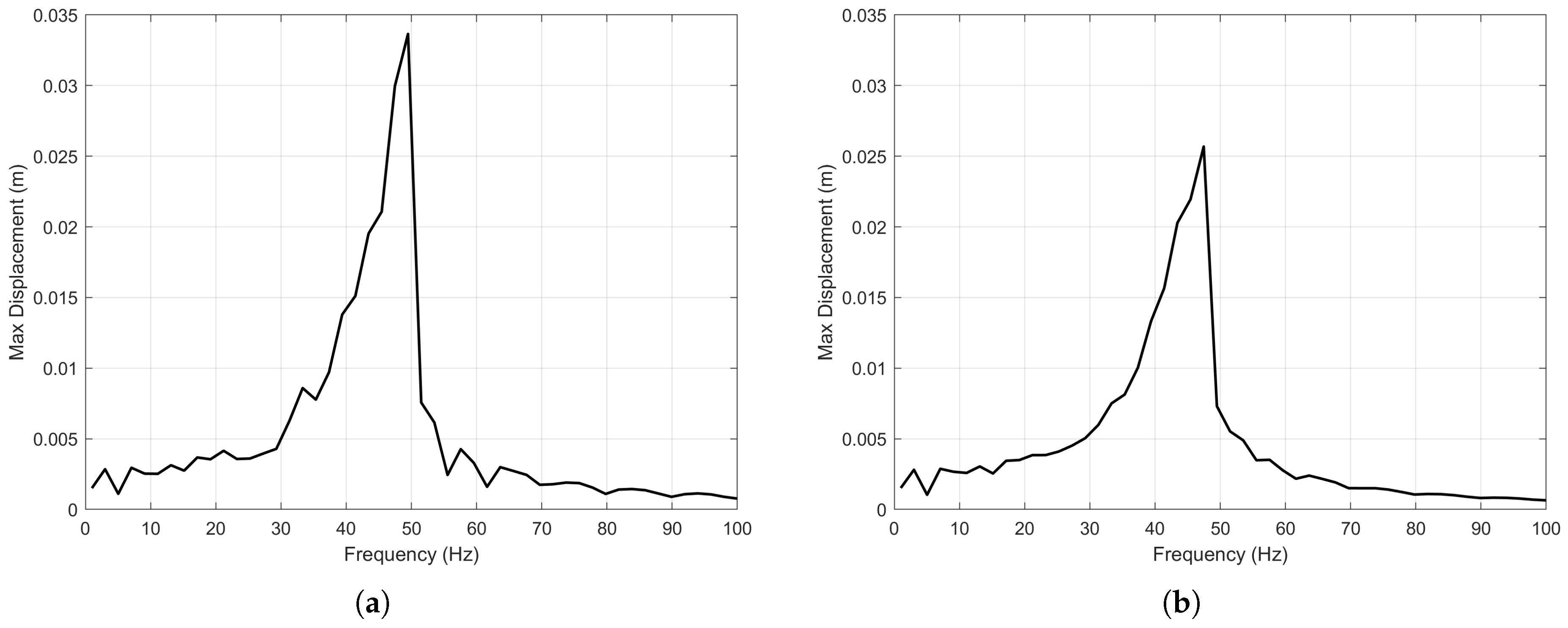
In Figure 7a, the maximum displacement of the middle magnet occurs at approximately 50 Hz, with a peak displacement of about 0.034 m; In Figure 7b, the maximum displacement of the middle magnet occurs at approximately 48 Hz, with a peak displacement of about 0.026 m.
Figure 7.
(a) Displacement-frequency curve: a = 0.5 g, c = 0.005 N/(m/s). (b) Displacement-frequency curve: a = 0.5 g, c = 0.01 N/(m/s).
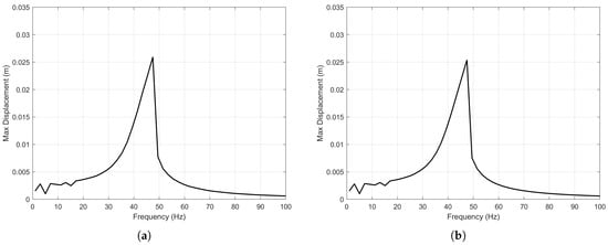
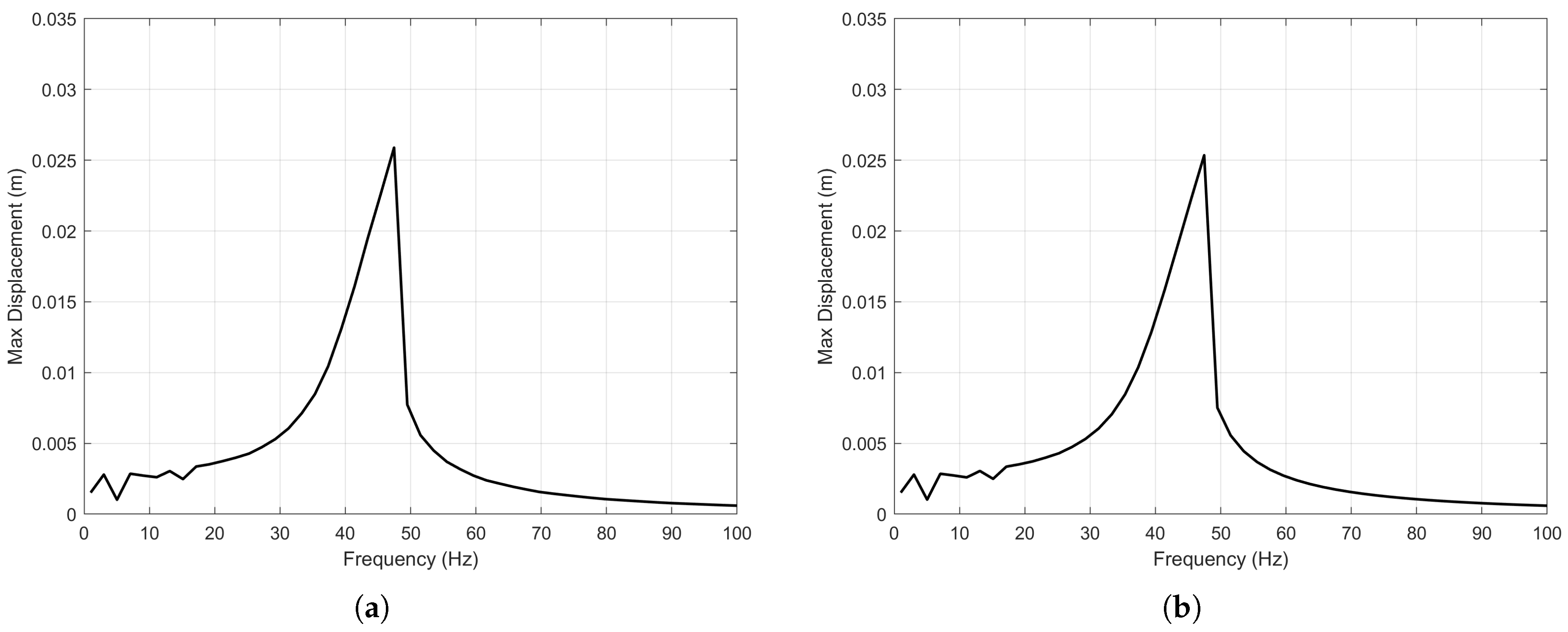
In Figure 8a, the maximum displacement of the middle magnet occurs at approximately 48 Hz, with a peak displacement of about 0.026 m; In Figure 8b, the maximum displacement of the middle magnet occurs at approximately 48 Hz, with a peak displacement of about 0.025 m.
Figure 8.
(a) Displacement-frequency curve: a = 0.5 g, c = 0.02 N/(m/s). (b) Displacement-frequency curve: a = 0.5 g, c = 0.05 N/(m/s).
The simulation results indicate that under different parameter conditions, the vibration amplitude of the magnetic levitation track vibration energy harvester exhibits a sudden drop phenomenon as the excitation frequency varies. As the excitation frequency changes from 0 Hz to approximately 48 Hz, the maximum displacement of the intermediate magnet increases with the excitation frequency. Upon reaching a frequency near 48 Hz, the maximum displacement value of the intermediate magnet rapidly decreases within a 10 Hz range of excitation frequency variation, followed by a gradual decline. Therefore, for a vibration energy harvester with given parameters, an idealized single-frequency excitation environment can achieve resonance with it, enabling higher-harvesting performance.
The simulation results also reveal the influence of different physical variables on the maximum displacement of the intermediate magnet. With a fixed system damping term, a higher acceleration value in the external excitation corresponds to a higher maximum displacement of the intermediate magnet. With damping set at N/(m/s) and acceleration values of g, g, and 1 g, the maximum displacements are m, m, and m, respectively. Under a given external excitation acceleration, the maximum displacement of the intermediate magnet first increases rapidly and then gradually decreases as the damping value rises. With an external excitation acceleration of g and system damping values of N/(m/s), N/(m/s), N/(m/s), N/(m/s), and N/(m/s), the maximum displacements were m, m, m, m, and m, respectively. This indicates that when system damping falls below a value near N/(m/s), the system stiffness becomes excessively low, potentially impairing the stable oscillation of the suspended magnet. Within the range exceeding this damping threshold, the displacement response generally decreases as damping increases. This preliminary finding suggests that appropriately reducing damping can lower system stiffness, thereby enhancing the harvesting performance in capturing low-frequency vibration energy.
Additionally, the simulation results in Figure 5, Figure 6, Figure 7 and Figure 8 express a distinct characteristic where the resonance peaks lean towards the higher frequency range. This is a typical hardening stiffness phenomenon associated with the nonlinear Duffing oscillator, induced by the magnetic repulsion forces. The observed sudden drop in amplitude represents the jump-down bifurcation point, where the system transitions from a high-energy resonant state to a low-energy state.
Therefore, this nonlinear characteristic offers a significant advantage over linear harvesters. The frequency band of track vibration is usually wide, and it’s difficult for energy harvesters to strictly match the complicated vibration environments. The hardening behavior shown effectively broadens the resonance bandwidth, allowing the harvester to maintain high-amplitude oscillations over a wider frequency range before the sudden drop occurs. This validates the broadband design objective.
It is worth noting that the nonlinear dynamics of the Duffing oscillator, including bifurcation phenomena and chaos, have been rigorously treated in classical texts such as Guckenheimer and Holmes [28]. In this paper, we focus on leveraging the well-known hardening stiffness characteristic to achieve a passive bandwidth expansion, to provide convenience for railway energy harvesting application.
4.2. Multi-Frequency Excitation Response Analysis
4.2.1. Power Spectrum Density Analysis of Vibration Data
Power spectral density (PSD) is a physical quantity used to describe the relationship between a signal’s energy (power) and frequency. Performing power spectral density analysis on track vibration acceleration provides a more intuitive and profound understanding of this type of track vibration characteristic, particularly the distribution of vibration energy in the frequency domain.
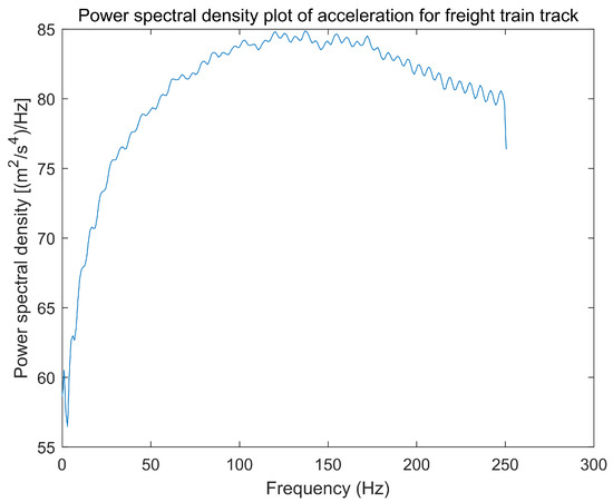
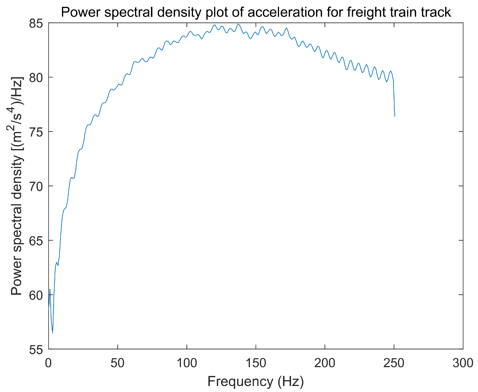
The data sources for this section include: the track vibration displacement data of freight trains operating at a speed of 64 km/h in a paper published by Pan et al. in 2018 and 2019 [29,30]; Track vibration acceleration data of Tongji University high-speed maglev integrated test line. These two datasets were specially selected to represent two distinct extremes of the track vibration environment: the freight train data exhibits the typical broadband low-frequency spectrum characteristics of heavy-haul transportation, while the maglev train data is characterized by narrowband high-frequency peaks. Analyzing these comparative scenarios allows us to comprehensively evaluate the adaptability and performance limits of the collector under different operating conditions.The results of the power spectral density analysis for the track vibration acceleration data of freight trains are shown in Figure 9.
Figure 9.
Power spectral density of acceleration for freight train track.
The results indicate that the peak values of the track acceleration power spectrum for freight trains are primarily concentrated within the 50 Hz to 200 Hz range, reaching a maximum value of approximately 85 (m2/s4)/Hz between 100 Hz and 150 Hz. Subsequently, the power spectral density gradually decreases starting around 170 Hz. Therefore, it can be preliminarily concluded that the track vibration energy of freight trains is primarily concentrated in the 50 Hz to 200 Hz frequency band, exhibiting a relatively wide frequency distribution and complex frequency components.
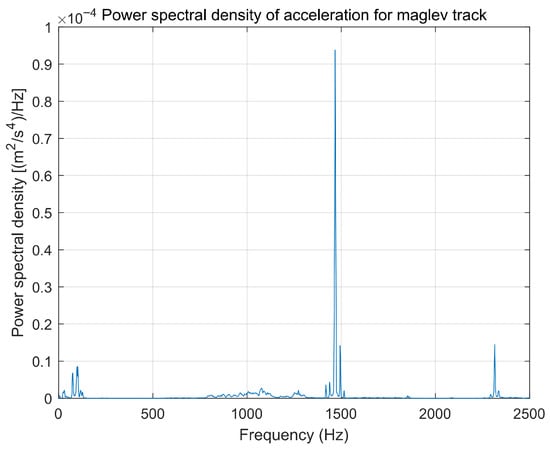
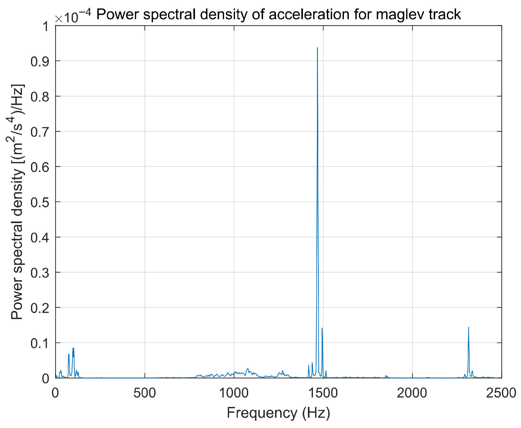
The power spectral density analysis results for the bridge vibration acceleration data of the maglev test line are shown in Figure 10.
Figure 10.
Power spectral density of acceleration for maglev track.
The results indicate that the acceleration power spectrum distribution of the maglev train bridge is relatively concentrated, with distinct peaks appearing near 97 Hz, 1469 Hz and 2314 Hz, with corresponding power spectral densities of 8.6 × 10⁻⁶ (m2/s4)/Hz, 9.4 × 10⁻⁵ (m2/s4)/Hz, and 1.4 × 10⁻⁵ (m2/s4)/Hz. This suggests that during maglev train operation, bridge vibration energy distribution is relatively concentrated and comparatively lower than that of freight train tracks. Additionally, the overall vibration frequency of freight train tracks is significantly lower than that of maglev bridges. Based on this, preliminary speculation suggests that electromagnetic energy harvesters coupled with magnetic levitation would exhibit higher harvesting performance in freight train scenarios than in maglev bridge scenarios. This hypothesis will be analyzed and validated in the next subsection.
4.2.2. Multi-Frequency Excitation Response Analysis Based on Runge-Kutta Methods
To systematically determine the optimal structural parameters, a numerical exhaustive search method was employed, utilizing the computational framework adopted by Gatti et al. [24] in their fundamental research, as shown in (6).
In this equation, E denotes the dissipated energy potential defined in (4), and is the equivalent damping ratio. The goal is to identify the optimal that maximizes the integral area under the power-frequency curve within the operational bandwidth, ensuring the harvester captures the maximum vibration energy from the track.
The optimization process based on the fourth-order Runge-Kutta (RK-4) algorithm is detailed as follows. Firstly, the system’s natural frequency is swept within the range of 0–1000 Hz, and the damping ratio is varied logarithmically from to . The intermediate magnet is assumed to be unity mass ( kg) to generalize the results.
Secondly, for each iteration step in the loop, the unknown physical parameters (equivalent stiffness k and damping coefficient c) are uniquely derived from the current pair of . Since relative displacement and acceleration are coupled physical quantities, they can be simultaneously calculated using a single Runge-Kutta algorithm iteration.
Finally, after obtaining the relative velocity between the intermediate magnet and other structures of the energy harvester, the total dissipated energy potential for each parameter combination is calculated according to (4), and the global maximum is identified to pinpoint the optimal design parameters.
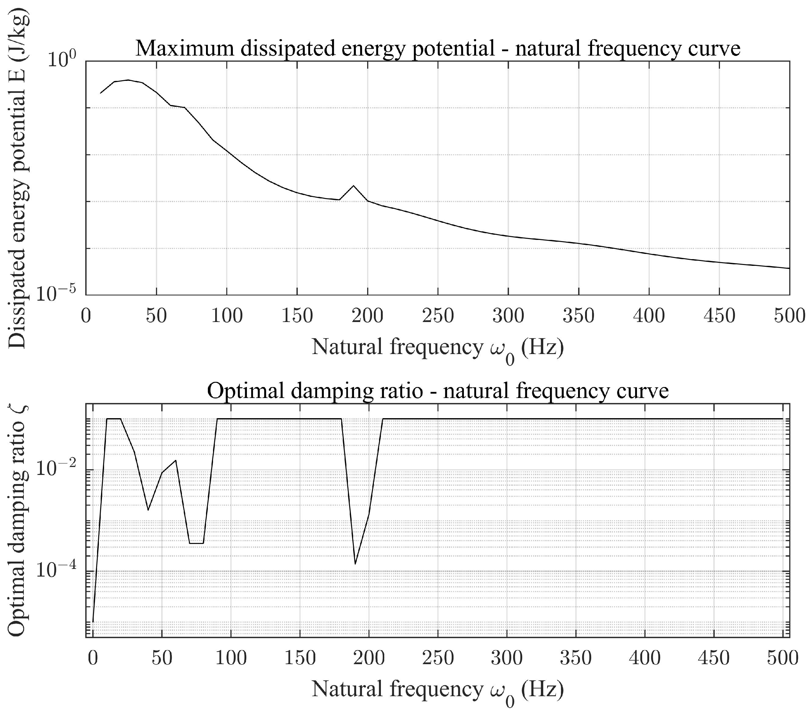
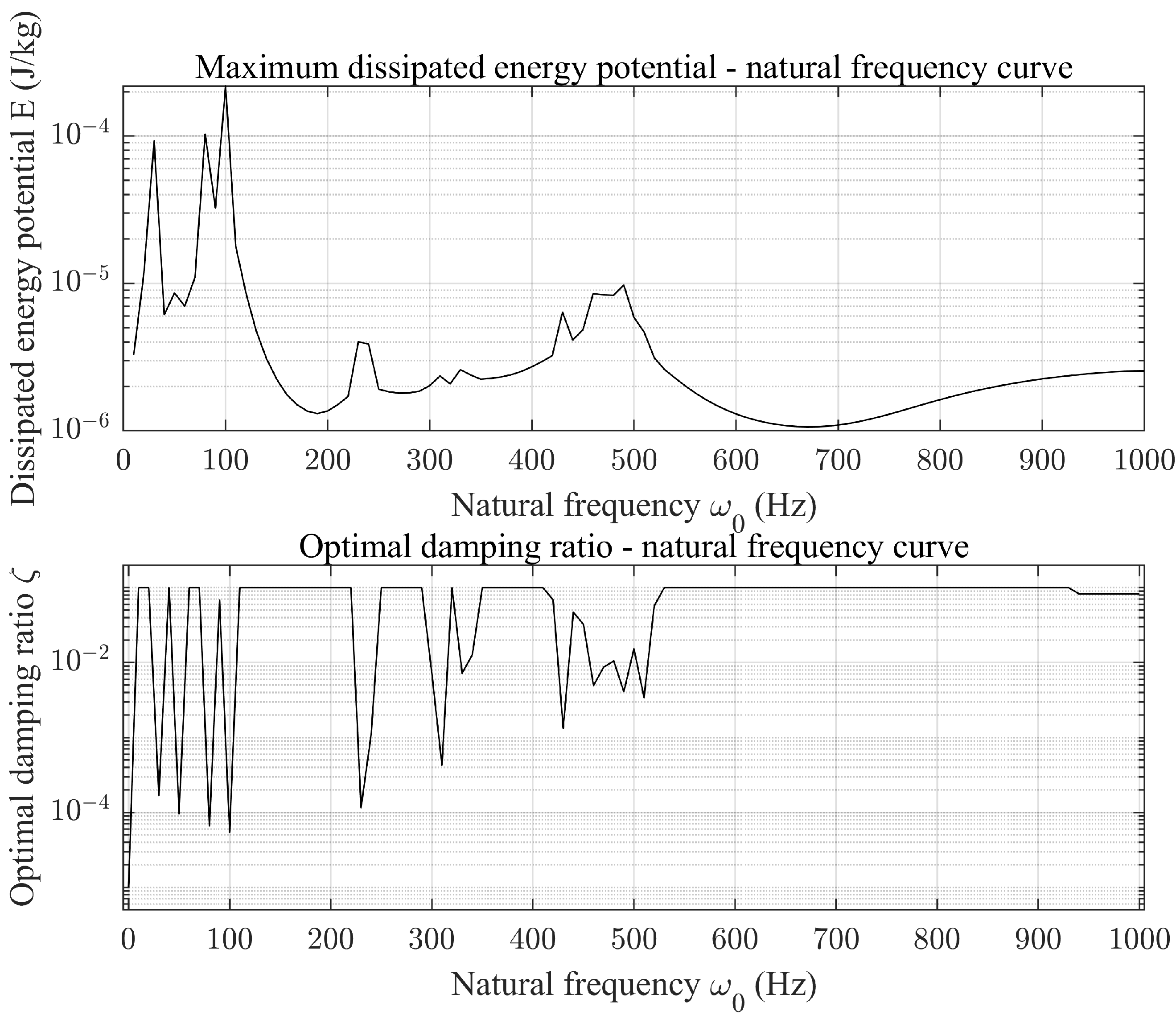
This analytical approach leverages the simplicity of the Runge-Kutta algorithm to rapidly and accurately determine relative displacements and velocities corresponding to each set of natural frequencies and damping ratios within the energy harvester. Integrating the product of velocity and damping yields the dissipated energy potential. Comparing the results identifies the maximum dissipated energy potential and its corresponding optimal combination of natural frequency and damping ratio—representing the optimal structural parameters for the electromagnetic vibration energy harvester under that excitation data. Through this analysis, curves showing the variation of maximum dissipated energy potential E and optimal damping ratio with respect to the natural frequency of the vibration energy harvester were obtained.
The dissipated energy potential and damping ratio curves for a freight train operating at 64 km/h and the maglev train on the Tongji University Maglev Test Line are shown in Figure 11 and Figure 12.
Figure 11.
Numerical analysis of energy harvesting effect for freight train tracks.
Figure 12.
Numerical analysis of energy harvesting effect for maglev tracks.
As shown in Figure 11, for freight train track, the dissipated energy potential reaches its maximum value of approximately 0.39 J/kg when the harvester’s natural frequency Hz and the system damping ratio . For maglev tracks in Figure 12, the dissipated energy potential reaches its maximum value of approximately 0.00021 J/kg when the harvester’s natural frequency Hz and the system damping ratio . The electromagnetic vibration energy harvester demonstrated better energy capture performance on freight train tracks compared to the maglev train bridge, validating its adaptability for low-frequency environmental energy harvesting.
5. Experimental Prototype Construction and Experimental Results
The experimental setup utilizes a vibration motor as the excitation source. To ensure stable mechanical coupling and withstand severe vibrations, a customized motor housing was designed using SolidWorks and manufactured through Stereolithography (SLA) 3D printing technology with photosensitive resin. This non-magnetic material was chosen to prevent magnetic flux leakage and eddy current damping. EPE foam was used as a filling material inside the motor housing to ensure stable vibration transmission.
The housing and motor are securely fixed with metal wires of 2.2 mm diameter to prevent loosening during operation. The main housing dimensions are 52 mm × 52 mm × 65 mm. After installing an adjustable top rod, the total height is approximately 110 mm. Magnets: The system employs ring-shaped NdFeB permanent magnets (outer diameter 20 mm, inner diameter 5 mm, thickness 5 mm) arranged in a repulsive configuration along the central guide rod. To reduce friction, the central rod is coated with graphite powder. The induction coil is wound with enameled copper wire of 0.15 mm diameter, with approximately 800 turns. To measure the output capability under load, a 6.4 ohm load resistor is connected in series with the induction coil. The output voltage and current are directly recorded using the analog input channels of a NI USB-6008 data acquisition card.
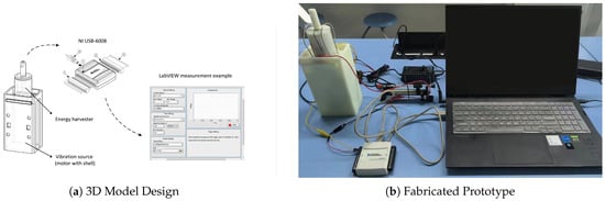
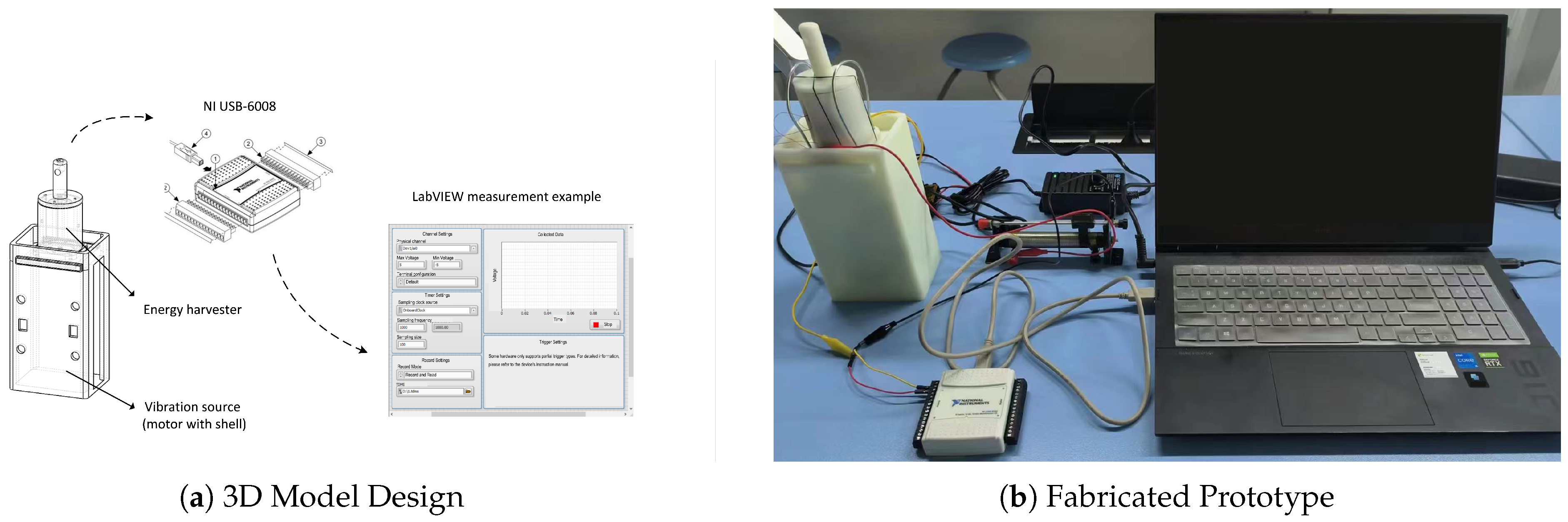
This experiment employs National Instruments data acquisition equipment for data collection. The data acquisition (DAQ) system comprises sensors, DAQ measurement hardware, and a computer. After debugging, it can measure the output voltage and current of the vibration energy harvester. Data reading and recording of the harvester’s output utilize the Voltage-Continuous Input and Current-Continuous Input examples within LabVIEW (version 2022). The external structure of the energy harvester was designed using SOLIDWORKS (version 2021). The experimental design is shown in Figure 13.
Figure 13.
Experimental design of the vibration energy harvester: (a) 3D Model design showing internal structure; (b) Fabricated prototype featuring four-point rigid fixation and 3D printed housing.
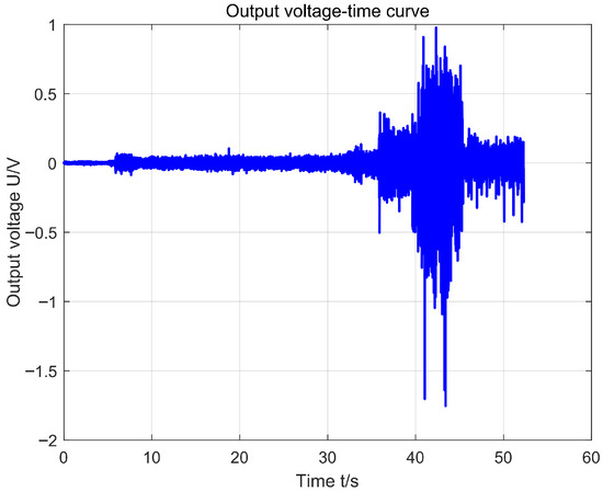
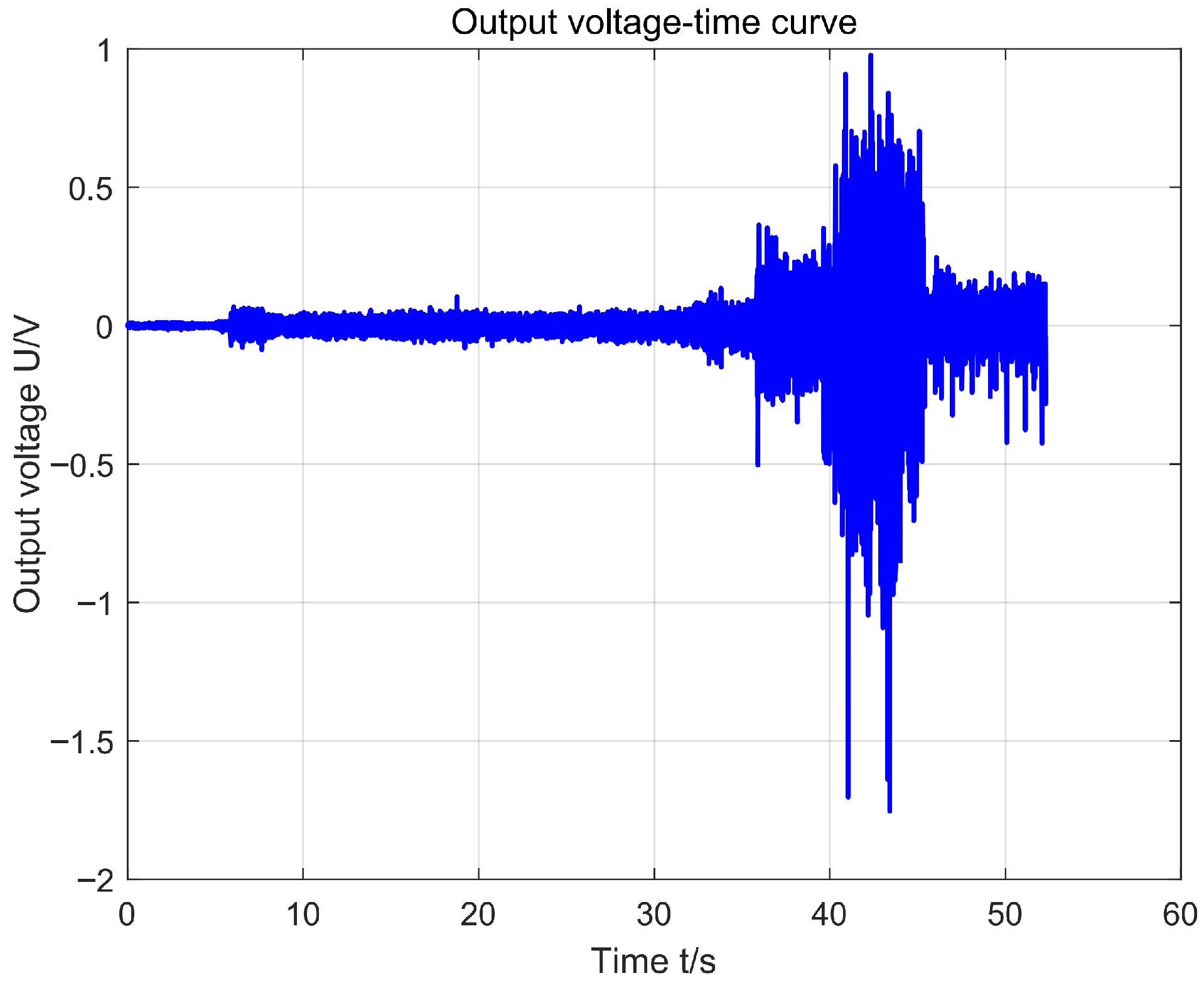
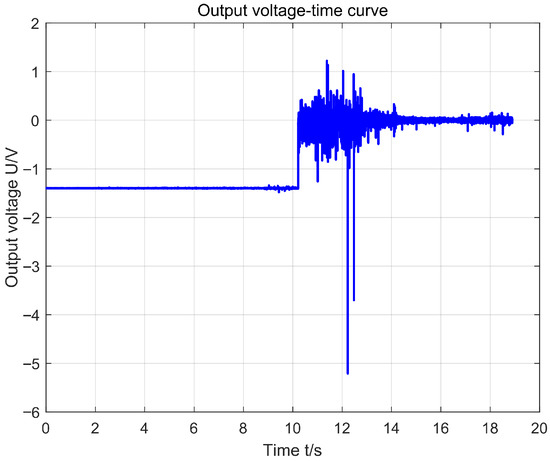
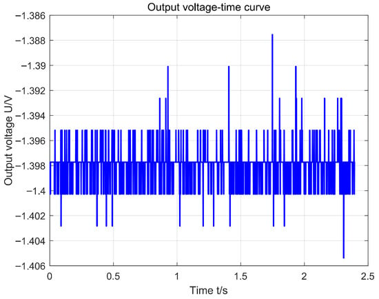
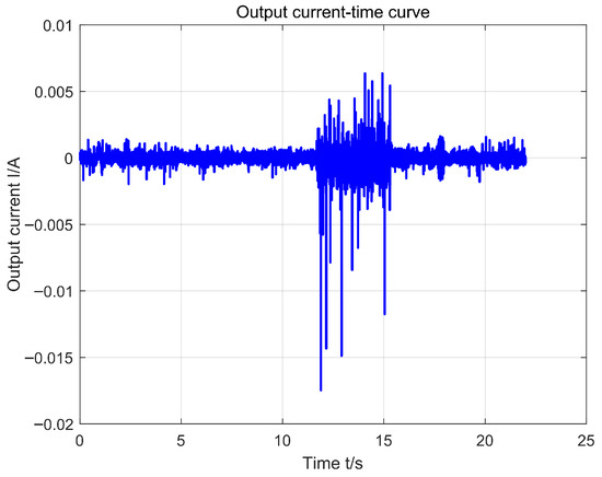
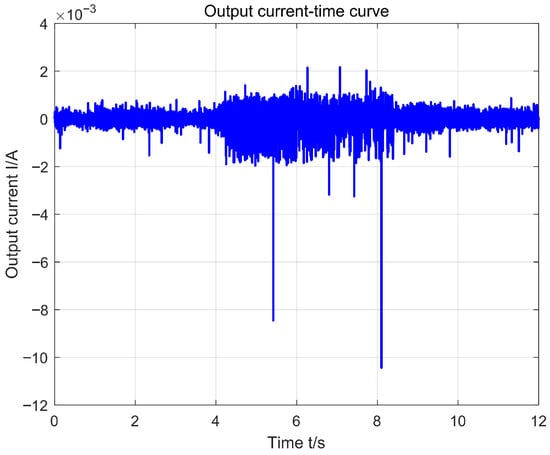
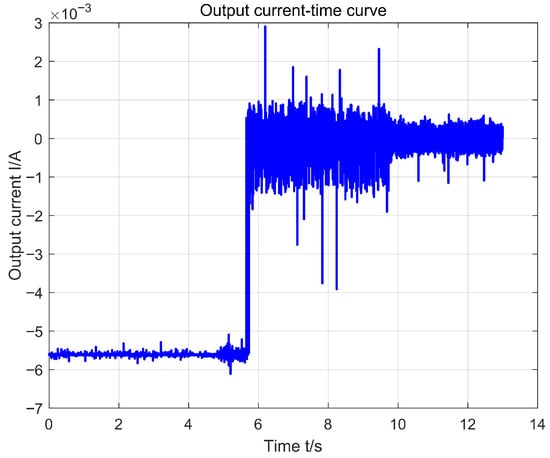
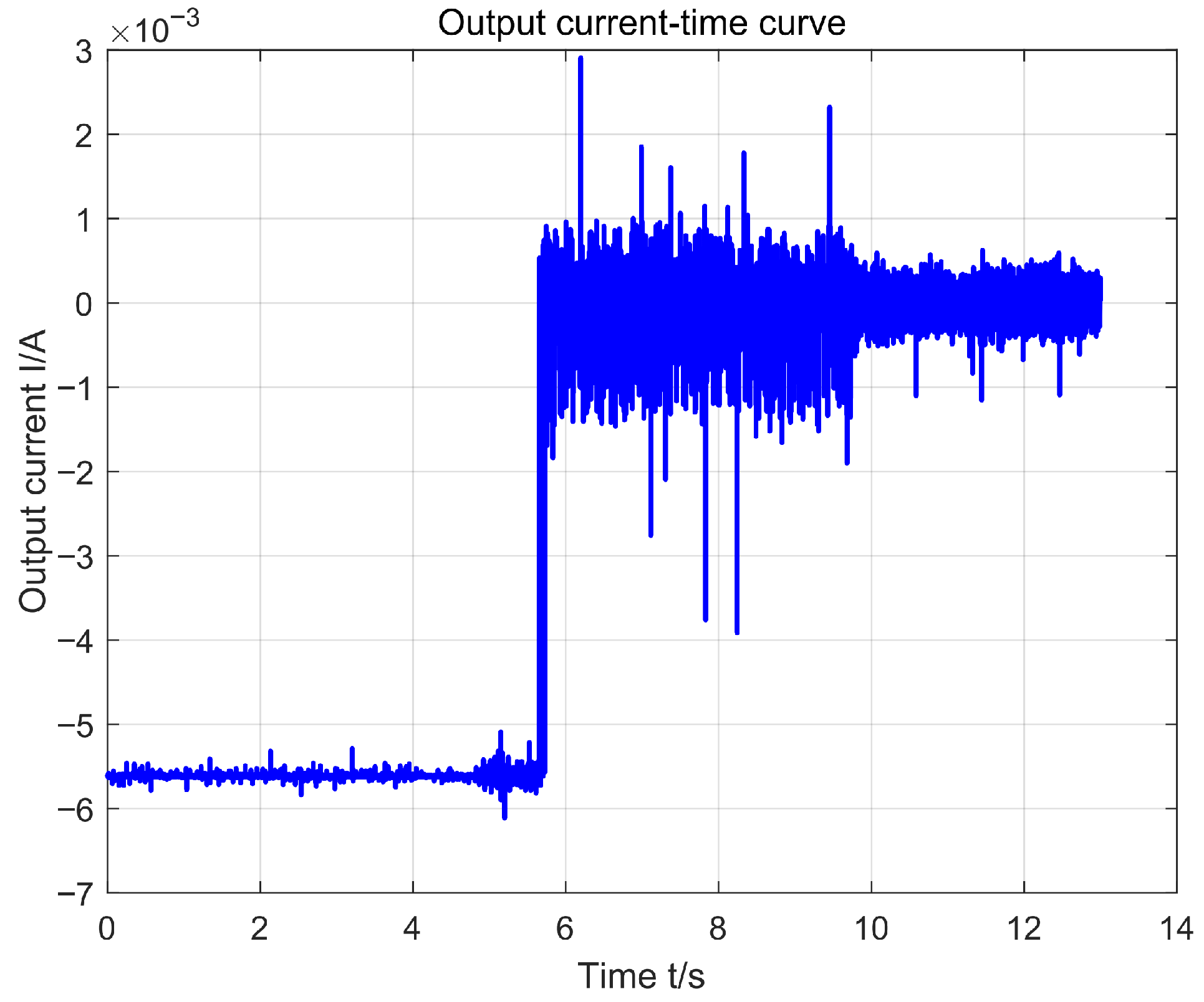
After processing and visualizing the LabVIEW output files using MATLAB software (version 2024b), the test results for the electromagnetic track vibration energy harvester are shown in Figure 14, Figure 15, Figure 16, Figure 17, Figure 18 and Figure 19.
Figure 14.
Output voltage-time curve of Group 1.
Figure 15.
Output voltage-time curve of Group 2.
Figure 16.
Output voltage-time curve of Group 3.
Figure 17.
Output current-time curve of Group 1.
Figure 18.
Output current-time curve of Group 2.
Figure 19.
Output current-time curve of Group 3.
Figure 14, Figure 15 and Figure 16 display the voltage measurement results, where Group 3 exhibited persistent zero-point drift, rendering the data invalid and subsequently excluded from further analysis. Figure 17, Figure 18 and Figure 19 present the current measurement results. Group 3 exhibited severe zero-point drift and poor output quality, leading to its exclusion from subsequent analysis. We suppose that during continuous high-intensity vibration operations, significant changes occur in parameters such as sensor circuit temperature, which caused persistent zero-point drift in Group 3. As shown in the figures, the harvester’s output voltage remained largely stable around V, peaking at V. The output current was generally stable around mA, with a maximum of mA. Calculations indicate the actual energy harvester’s output power averages approximately mW, with a peak output power of mW.
Using the nominal parameters listed in Table 1 (estimated based on the physical dimensions and magnetic properties of the prototype), the theoretical peak change rate of magnetic flux () in resonance state is predicted to be approximately 1.9 V. The peak voltage measured by the prototype is 1.431 V, and the experimental results are consistent with the simulation results in terms of magnitude, with a deviation of about 25%. This reasonable difference validates the effectiveness of the proposed model, which is attributed to the inevitable uncertainty in estimating damping coefficients and magnetic flux leakage in manually fabricated prototypes, which have been simplified in the theoretical model.
Table 1.
Fixed parameters and variable ranges used in the numerical simulation.
These experimental results demonstrate that the energy harvester’s output level meets the requirements for low-power wireless sensor nodes, providing preliminary validation of the feasibility of applying magnetically levitated electromagnetic vibration energy harvesters to sensor self-powering solutions.
6. Conclusions
This paper proposes a magnetic levitation coupled electromagnetic vibration energy harvester for sensor nodes in low-power-demand trackside wireless sensor networks. Theoretical analysis and design are conducted to enhance the harvesting performance. Our comparative analysis indicates that due to the high frequency and low vibration amplitude of the maglev track, its performance on the maglev track is not ideal. Therefore, the main application scenario for this equipment is identified as heavy freight transportation infrastructure.
Despite the feasibility, there are still several challenges in practical applications. First, while the nonlinear design broadens the bandwidth, significant variations in train speed may still shift the dominant vibration frequency away from the resonant range. Secondly, in practical applications, circuits for rectification and storage will bring additional efficiency losses, which would be discussed in future work. Thirdly, the harsh railway environment (such as shock, dust and moisture) requires further optimization the design of the harvester’s size, shape and installation. Long-term field testing to gather statistical vibration data under varying environmental conditions is also essential.
It is worth noting that the simplification made in Section 2, which treats track vibration directly as the base excitation, actually reduces the harvester to a single-degree-of-freedom model. Future work will address this issue by considering the flexible coupling to better match practical applications.
In summary, the proposed magnetic levitation harvester may advance technological innovation and development in rail transit power supply solutions. It supports the modernization of intelligent rail operations and offers new perspectives for energy transition in transportation infrastructure.
Author Contributions
Conceptualization, Z.L. and L.R.; methodology, Z.L.; software, A.L. and M.T.; validation, Z.L., L.R. and Y.S.; formal analysis, Z.L.; investigation, L.R.; resources, Y.S.; data curation, M.T.; writing—original draft preparation, Z.L. and L.R.; writing—review and editing, Y.S.; visualization, A.L.; supervision, Y.S.; project administration, Y.S.; funding acquisition, Y.S. All authors have read and agreed to the published version of the manuscript.
Funding
This research was funded by the National Natural Science Foundation of China (52522217 and 52441203), the China National Railway Group Science and Technology Program (K2024T005).
Data Availability Statement
The original contributions presented in this study are included in the article. Further inquiries can be directed to the corresponding author.
Acknowledgments
The authors express their gratitude to Pan from Tongji University, for his permission to reference and utilize the experimental results presented in his published article, which significantly supported the analysis in this study. The authors also thank the College of Transportation, Tongji University for providing the maglev track vibration data and experimental facilities.
Conflicts of Interest
The authors declare no conflict of interest.
Abbreviations
The following abbreviations are used in this manuscript:
| PSD | Power Spectral Density |
| RK-4 | Fourth-order Runge-Kutta algorithm |
| DAQ | Data Acquisition |
References
- He, X.F.; Qi, R.; Cheng, Y.Q.; Zhang, C.; Shang, Z. Wireless wind speed sensor powered by wind-induced vibration energy harvester. J. Vib. Eng. 2017, 30, 290–296. [Google Scholar]
- Paccoia, V.D.; Bonacci, F.; Clementi, G.; Cottone, F.; Neri, I.; Mattarelli, M. Toward Field Deployment: Tackling the Energy Challenge in Environmental Sensors. Sensors 2025, 25, 5618. [Google Scholar] [CrossRef] [Scilit]
- The State Council Information Office of China. China’s Energy Transition; Report; The State Council Information Office of China: Beijing, China, 2024.
- Fei, L.; Yin, Y.; Yang, M.; Zhang, S.; Wang, C. Wearable solar energy management based on visible solar thermal energy storage for full solar spectrum utilization. Energy Storage Mater. 2021, 42, 636–644. [Google Scholar] [CrossRef] [Scilit]
- Ginsberg, M.; Zhang, Z.; Atia, A.A.; Venkatraman, M.; Esposito, D.V.; Fthenakis, V.M. Integrating Solar Energy, Desalination, and Electrolysis. Sol. RRL 2022, 6, 2100732. [Google Scholar] [CrossRef] [Scilit]
- Sinclair, K.; Copping, A.E.; May, R.; Bennet, F.; Warnas, M.; Perron, M.; Elmqvist, Å.; DeGeorge, E. Resolving environmental effects of wind energy. WIREs Energy Environ. 2018, 7, e301. [Google Scholar] [CrossRef] [Scilit]
- Clark, C.E.; Barter, G.; Shaler, K.; DuPont, B. Reliability-based layout optimization in offshore wind energy systems. Wind Energy 2022, 25, 125–148. [Google Scholar] [CrossRef] [Scilit]
- Abid, K.; Sharma, A.; Ahmed, S.; Srivastava, S.; Velazco, A.T.; Teodoriu, C. A Review on Geothermal Energy and HPHT Packers for Geothermal Applications. Energies 2022, 15, 7357. [Google Scholar] [CrossRef] [Scilit]
- Sun, Y.G.; He, Z.; Xu, J.; Sun, W.; Lin, G. Dynamic analysis and vibration control for a maglev vehicle-guideway coupling system with experimental verification. Mech. Syst. Signal Process. 2023, 188, 109954. [Google Scholar] [CrossRef] [Scilit]
- Qiang, H.; Xiao, C.; Huang, H.; Hai, Y.; Sun, Y. Yaw feedback control of active steering vehicle based on differential flatness theory. J. Theor. Appl. Mech. 2025, 63, 131–149. [Google Scholar] [CrossRef] [Scilit] [PubMed]
- Podder, P.; Amann, A.; Roy, S. A bistable electromagnetic micro-power generator using FR4-based folded arm cantilever. Sens. Actuators A Phys. 2015, 227, 39–47. [Google Scholar] [CrossRef] [Scilit]
- Qiu, J.; Liu, X.; Chen, H.; Xu, X.; Wen, Y.; Li, P. A Low-Frequency Resonant Electromagnetic Vibration Energy Harvester Employing the Halbach Arrays for Intelligent Wireless Sensor Networks. IEEE Trans. Magn. 2015, 51, 1–4. [Google Scholar] [CrossRef] [Scilit]
- Zuo, J.; Liu, W.; Bai, Y.; Du, F.; Guo, S.; Li, P. Energy harvesting solutions for railway transportation: A comprehensive review. Renew. Energy 2023, 202, 56–87. [Google Scholar] [CrossRef] [Scilit]
- Cottone, F.; Vocca, H.; Gammaitoni, L. Nonlinear energy harvesting. Phys. Rev. Lett. 2009, 102, 080601. [Google Scholar] [CrossRef] [Scilit]
- Erturk, A.; Inman, D.J. Broadband piezoelectric power generation on high-energy orbits of the bistable Duffing oscillator with electromechanical coupling. J. Sound Vib. 2011, 330, 2339–2353. [Google Scholar] [CrossRef] [Scilit]
- Zhang, T.; Pan, Y.; Lin, T.; Liu, Z.; Wang, J. An electromagnetic vibration energy harvesting system based on series coupling input mechanism for freight railroads. Appl. Energy 2024, 353, 122116. [Google Scholar] [CrossRef] [Scilit]
- Wang, Z.Y.; Ding, H.; Chen, L.Q. Research on two-degree-of-freedom magnetic levitation nonlinear vibration energy harvesting. J. Vib. Shock 2016, 35, 55–58. [Google Scholar]
- Chen, C.M.; Yuan, T.C.; Chen, L.Q. Design and analysis of a novel triangular electromagnetic vibration energy harvester. J. Vib. Shock 2021, 40, 52–59. [Google Scholar]
- Liu, X.J.; Wang, S.Q.; Zhu, Q.; Jiang, J. Design and testing of an electromagnetic vibration energy harvester based on Halbach permanent magnet array. J. Jinling Inst. Technol. 2023, 39, 44–49. [Google Scholar]
- Zhang, K.; Zhang, B.; Zhao, H.J.; Feng, W.; Shen, H.; Liu, Z.; Liu, B. Piecewise nonlinear electromagnetic vibration energy harvester. Micronanoelectron. Technol. 2023, 60, 764–769. [Google Scholar]
- Holm, P.; Imbaquingo, C.; Mann, B.P.; Bjørk, R. High power electromagnetic vibration harvesting using a magnetic dumbbell structure. J. Sound Vib. 2023, 546, 117446. [Google Scholar] [CrossRef] [Scilit]
- Gao, M.; Wang, P.; Wang, Y.; Yao, L. Self-Powered ZigBee Wireless Sensor Nodes for Railway Condition Monitoring. IEEE Trans. Intell. Transp. Syst. 2018, 19, 900–909. [Google Scholar] [CrossRef] [Scilit]
- Yang, Y.; Liu, C.; Lai, S.K.; Chen, Z.; Chen, L. Frequency-dependent equivalent impedance analysis for optimizing vehicle inertial suspensions. Nonlinear Dyn. 2025, 113, 9373–9398. [Google Scholar] [CrossRef] [Scilit]
- Gatti, G.; Brennan, M.J.; Tehrani, M.G.; Thompson, D.J. Harvesting energy from the vibration of a passing train using a single-degree-of-freedom oscillator. Mech. Syst. Signal Process. 2016, 66–67, 785–792. [Google Scholar] [CrossRef] [Scilit]
- Zhao, H.J. Research on Magnetic Levitation-Based Low-Frequency Vibration Energy Harvesting Technology. Master’s Thesis, Henan University of Technology, Zhengzhou, China, 2023. [Google Scholar]
- Kotdawala, V.R.; Kamat, V.N. Electromechanical Modeling and Simulation of Piezoelectric Energy Harvester using MATLAB SIMULINK. Int. J. Adv. Eng. Res. Dev. 2018, 5, 30–37. [Google Scholar]
- Pečioski, D.; Shishkovski, D.; Ignajatovska, A.A.; Markovska, S.D.; Gavriloski, V. Modeling and Simulation of an Electromagnetic Energy Harvesting System. In Proceedings of the 2024 13th Mediterranean Conference on Embedded Computing (MECO), Budva, Montenegro, 10–14 June 2024; pp. 512–515. [Google Scholar]
- Guckenheimer, J.; Holmes, P. Nonlinear Oscillations, Dynamical Systems, and Bifurcations of Vector Fields; Springer: New York, NY, USA, 1983. [Google Scholar]
- Lin, T.; Pan, Y.; Chen, S.; Zuo, L. Modeling and field testing of an electromagnetic energy harvester for rail tracks with anchorless mounting. Appl. Energy 2018, 213, 219–226. [Google Scholar] [CrossRef] [Scilit]
- Pan, Y.; Lin, T.; Qian, F.; Liu, C.; Yu, J.; Zuo, J.; Zuo, L. Modeling and field-test of a compact electromagnetic energy harvester for railroad transportation. Appl. Energy 2019, 247, 309–321. [Google Scholar] [CrossRef] [Scilit]

Disclaimer/Publisher’s Note: The statements, opinions and data contained in all publications are solely those of the individual author(s) and contributor(s) and not of MDPI and/or the editor(s). MDPI and/or the editor(s) disclaim responsibility for any injury to people or property resulting from any ideas, methods, instructions or products referred to in the content. |
© 2026 by the authors. Licensee MDPI, Basel, Switzerland. This article is an open access article distributed under the terms and conditions of the Creative Commons Attribution (CC BY) license.