


Abstract
With the increasing use of massage robots as direct-contact rehabilitation devices, their evaluation must address both equipment failures and use-related risks. This study presents a prototype-stage assessment framework for a seated knee-adjustment bionic massage robot that integrates failure mode, effects, and criticality analysis (FMECA), task analysis, and fuzzy analytic hierarchy process (FAHP) weighting based on a fuzzy complementary judgment matrix. FMECA identified 28 failure modes across the actuation, sensing, and drive-control subsystems. Simulated-use testing involving 15 operators and 15 healthy adults acting as simulated patients comprised 19 observable subtasks and recorded 66 use errors across 285 subtask opportunities. The normalized scores for the actuation, sensing, drive-control, and operational-safety indicators were 0.796, 0.691, 0.808, and 0.768, respectively. Interval-based aggregation yielded Q = 0.848 (“Very Good”), whereas direct weighting of the same normalized inputs yielded = 0.767, within the “Good” interval. Across ∈ [0, 1], Q ranged from 0.753 to 0.902. A same-panel expert assessment yielded 0.904 and the same grade, although this comparison did not constitute independent validation. Inaccurate pressure-sensor output had the highest risk priority number of 32, while confusion between left- and right-side pressure readings was the most frequent use error, with 11 occurrences. The framework supports prototype-stage risk identification and prioritization but does not establish clinical efficacy, certified safety, or long-term reliability.
1. Introduction
As the global population ages and the burden of chronic musculoskeletal diseases increases, the demand for rehabilitation services continues to grow accordingly [1,2]. According to a systematic analysis published in the 2019 Global Burden of Disease Study, more than 2.41 billion people worldwide could benefit from rehabilitation services to recover from health impairments, with musculoskeletal diseases being one of the primary sources of rehabilitation demand [1]. Furthermore, the growing burden of osteoarthritis is particularly striking [2]. The 2021 Global Burden of Disease Study estimated that the burden of osteoarthritis continued to rise between 1990 and 2020 and is projected to increase significantly by 2050 [2]. Against this backdrop, the question of how to provide accessible and consistent rehabilitation interventions through medical devices and rehabilitation robots has become increasingly important in the fields of rehabilitation medicine, medical device engineering, and human–machine interaction safety.
Massage and tuina therapy are important non-pharmacological interventions in the management of musculoskeletal pain and dysfunction [3,4]. Clinical studies have shown that massage therapy can improve function and symptoms in patients with chronic low back pain [5] and has demonstrated certain efficacy and safety in individuals with knee osteoarthritis [4,6]. However, traditional manual massage relies heavily on the therapist’s experience and clinical judgment and is influenced by their physical condition [7,8]. There can be considerable variation among practitioners in the magnitude of force applied, the direction of force, contact points, and duration of treatment, and these variations may affect the consistency and reproducibility of the therapeutic process [8,9]. For techniques that require simultaneous acupoint localization and directional force application while the patient is standing or sitting—such as the “Seated Knee Adjustment Method”—the dependence on the practitioner is even more pronounced [10]. Converting the key movements, biomechanical parameters, and operational procedures of massage techniques into a robotic system that is controllable, recordable, and evaluable holds clear clinical and engineering significance [7,9].
Massage robots offer a new technological pathway for standardizing tuina techniques [9,11]. In recent years, related research has evolved from simple mechanical actuation mechanisms to complex systems integrating sensor feedback, visual recognition, Internet of Things (IoT) connectivity, and human–machine interaction [7,9,12]. For example, preliminary research on the EMMA electronic massage system indicates that automated massage devices can achieve a certain level of acceptability and feasibility in real-world service scenarios [13]; research on IoT-based medical massage robots also suggests that remote connectivity, system failure handling, and data exchange are becoming integral components of massage robot design [14]. The work of these researchers demonstrates that massage robots are evolving from simple motion-replication devices into human–machine interactive medical robot systems capable of therapeutic interaction, perceptual feedback, and operational decision-making [7,9,11].
This transformation has also significantly heightened the importance of reliability and operational safety assessments [15,16]. Unlike general rehabilitation assistive devices, massage robots require continuous contact with patients’ soft tissues or acupoint areas and apply controlled external forces through their actuators [7,15]. Loose actuator connections, misalignment of the massage head, pressure sensor drift, control system hysteresis, or communication anomalies can all cause the actual therapeutic dose to deviate from the preset range. These deviations may alter the mechanical treatment dose, including force magnitude, force direction, contact location, and treatment duration. Safety research in the field of physical human–robot interaction has also pointed out that when a robot comes into direct contact with the human body, safety depends not only on the mechanical structure itself, but also on factors such as speed, force, mass, control response, and contact detection [15,17,18]. The various potential factors associated with massage robots are further intertwined with therapeutic techniques, changes in patient posture, and operator interface decisions, forming a risk chain that is more complex than that of ordinary electromechanical devices [15,16,19].
Medical device risk management and usability engineering standards also emphasize that safety assessments should not focus solely on component failures but should also cover intended use, use scenarios, reasonably foreseeable misuse, and human-related risks [20,21]. ISO 14971 requires the systematic identification of hazards, risk estimation and evaluation, and the implementation of risk controls throughout the entire life cycle of a medical device [20]. IEC 62366-1 further integrates usability engineering into the medical device safety process, emphasizing the impact of user interfaces, task flows, and use errors on safety [21]. IEC 80601-2-78 specifies particular requirements for the basic safety and essential performance of medical robots that physically interact with patients with impairments [22]. Its scope covers rehabilitation, assessment, compensation, and alleviation related to patients’ movement functions [22]. Although existing standards provide a fundamental principled basis for the preclinical safety assessment of massage robots, they do not directly offer a quantitative evaluation pathway applicable to early-stage prototypes, scenarios with limited failure data, and situations where human–machine interaction is deeply intertwined [16,23].
Existing research on massage robots primarily focuses on mechanical design, control strategies, sensor feedback, or preliminary application feasibility; however, reliability evaluations of the overall system—including the actuation, sensing, and drive-control subsystems, as well as operator task flows—remain relatively insufficient [9,11,16]. Traditional reliability evaluations often rely on long-term operational data or large-sample failure statistics, whereas early-stage medical rehabilitation prototypes typically have not yet accumulated sufficient operational failure data or real-world clinical usage data [11,16].
Furthermore, while expert scoring alone can be used for preliminary assessments, it struggles to adequately capture uncertainty and the relative importance of different indicators; while FMECA alone can identify component failure modes, it tends to overlook user errors in task phases such as operator readings, parameter settings, patient positioning, and treatment start/stop procedures [19,23,24]. The fuzzy analytic hierarchy process (FAHP) can address multi-criteria weighting issues under conditions of uncertainty [24]; FMECA can be used to systematically identify failure modes and their severity [25]; and task analysis is suitable for decomposing human–machine interaction processes and capturing use errors [26]. The contribution of this integration is to place the normalized equipment-risk inputs derived from FMECA and the operational-safety input derived from task analysis within a common FAHP-weighted assessment structure. This enables equipment failures and observed use errors to be considered together at the prototype stage while preserving the subsystem scores and individual risk rankings.
This study integrates FAHP, FMECA, and task analysis to assess the reliability and operational safety of a seated knee-adjustment bionic massage robot prototype. FMECA characterizes subsystem failure risks, whereas task analysis identifies and quantifies use errors. Indicator weights are derived using FAHP based on a fuzzy complementary judgment matrix. The normalized risk inputs are subsequently combined through interval-based grade aggregation to obtain a composite score. The case study examines risk priorities and indicator scores, with a descriptive comparison between the composite score and ratings from the same expert panel.
2. Materials and Methods
2.1. Study Design, Evaluation Boundary, and Study Object
This study focuses on a seated knee-adjustment bionic massage robot prototype, which is a type of direct-contact rehabilitation massage robot. During treatment, this type of device requires continuous contact with the patient’s knee soft tissues or acupoint areas and applies external forces with specific directional and amplitude requirements through its actuation subsystem. Therefore, its safety depends not only on the reliability of the mechanical structure, sensing subsystems, and drive-control subsystem, but is also influenced by the operator’s task execution, the information presented via the human-machine interface, and changes in the patient’s posture.
To avoid overinterpretation of the evaluation results at the prototype stage, this paper first clarifies the scope of the study. The evaluation in this paper primarily covers two aspects: the device itself and the usage process. The device itself comprises the actuation subsystem, sensing subsystems, and a drive-control subsystem, which correspond to functions such as leg fixation, massage head positioning, pressure and rotational motion output, pressure and angle feedback, power supply, motion control, and interface display, respectively; the usage process includes tasks performed by the operator during the treatment workflow, such as determining the patient’s position, sensor attachment, massage head alignment, treatment start/stop, and reading data from the interface.
It should be noted that the evaluation results presented in this paper primarily reflect evidence of human-machine system reliability and operational safety during the prototype stage prior to clinical application. They do not include long-term treatment outcomes in actual patients, disease improvement effects, multicenter clinical safety data, or failure rates throughout the full life cycle of a commercialized product. Subsequent comprehensive evaluation scores should be understood as interim evaluation results based on the current prototype, the current metric system, and the current testing conditions; they should not be equated with clinical efficacy validation or post-market safety verification.
2.2. Task Workflow and Robotic Decomposition of the Seated Knee Adjustment Technique
The seated knee adjustment technique is the target treatment procedure simulated by the prototype in this study. In traditional practice, the physician sits facing the patient, holds the patient’s legs with both hands, and places both thumbs on the inner and outer knee-eye acupoints; the patient slowly stands up and sits back down in response to verbal cues, while the physician simultaneously applies upward and backward pressure with both thumbs as the patient’s posture changes dynamically [10]. The key to this therapeutic technique lies not merely in performing the pressing motions, but in maintaining coordination between knee positioning, changes in the patient’s posture, the directional application of force, and the practitioner’s rhythm [10].
When applying this therapeutic technique to robotic output, from the perspective of robotic implementation, the technique can be broken down into a series of sequential tasks, including patient positioning, leg stabilization, localization of the knee-eye acupoints, attachment of angle sensors, alignment of the massage head, monitoring of the standing or sitting process, synchronized force application, reading of pressure and angle data, and control of treatment start and stop. These tasks encompass both the movements of the device itself and the interaction between the operator and the human-machine interface. If positioning errors, force application deviations, or other issues occur at any stage, they may alter the actual therapeutic dose or increase operational risks.
Therefore, this paper does not view the massage robot merely as a mechanical actuator but defines it as a human-machine system comprising the device itself, the operator, changes in the patient’s posture, and the human-machine interface. This task decomposition provides a procedural basis for subsequent operational safety analysis and task error logging.
To replicate the therapeutic movements of the aforementioned seated knee adjustment method, the robot must meet three categories of functional requirements. The actuator subsystem must secure the patient’s leg, position the massage head in space, and perform multi-degree-of-freedom massage movements; the sensing subsystem must collect real-time data on the massage head’s applied force and the knee joint angle to provide feedback for closed-loop control; and the drive-control subsystem must coordinate the various moving components according to the treatment protocol and provide readable information to the operator via the human-machine interface. These functions collectively define the scope and boundaries of the subsequent reliability evaluation, as shown in Figure 1.
Figure 1.
Functional decomposition of the seated knee-adjustment bionic massage robot. The system comprises the actuation, sensing, and drive-control subsystems, together with their principal functional components.
2.3. Massage Robot System Architecture
2.3.1. Mechanical Actuation and Patient-Contact Structure
The actuation subsystem of the seated knee-adjustment bionic massage robot prototype is shown in Figure 2. It primarily consists of a base, leg supports, a lifting mechanism, a massage mechanism, a rotation mechanism, and a massage head. The base maintains the stability of the entire device and reduces the risk of displacement caused by changes in the center of gravity or external disturbances during treatment. The leg support consists of an L-shaped bracket and a slide rail bracket, which secure the patient’s lower leg and adjust the relative position between the knee and the massage head according to the patient’s body type.
Figure 2.
Mechanical structure of the seated knee-adjustment bionic massage robot: 1, L-shaped leg support; 2, rotation mechanism; 3, massage head; 4, pressure sensor; 5, massage mechanism; 6, lifting mechanism; 7, base; 8, power interface; and 9, serial display.
The lifting mechanism comprises a lifting actuator and a lifting arm, designed to replicate the vertical translational freedom of a therapist’s arm; a parallelogram linkage mechanism enhances motion stability and maintains a stable position once the massage mechanism reaches the target height. The bionic massage actuator in the massage assembly uses a short-stroke actuator to replicate pressing motions through forward and backward movements; the rotational mechanism uses a motor to drive the bionic massage actuator’s rotation, simulating the freedom of thumb rotation.
Therefore, the reliability of the actuation subsystem is primarily reflected in aspects such as support stability, leg fixation reliability, positioning accuracy of the target knee area, transmission continuity, and the safety of the massage head connection. These are key risk sources that must be identified in the subsequent FMECA analysis.
2.3.2. Force and Knee-Angle Sensing
The sensing subsystem provides mechanical and postural feedback during treatment. Since the pressure applied in the seated knee adjustment method must match the changes in the patient’s knee angle as they stand up and sit down, the system uses an angle sensor to monitor knee posture and combines this with pressure sensors at the massage head to measure the actual applied force, thereby supporting closed-loop feedback control and dynamic force adjustment.
The embedded pressure sensor used for closed-loop force control has a measurement range of 0–100 N. It communicates with the STM32 microprocessor through an intelligent pressure transmitter using the RS485–Modbus protocol. The IM948 10-axis attitude sensor transmits knee-angle measurements wirelessly to the microprocessor via Bluetooth. The reliability of the sensing subsystem is primarily reflected in the accuracy of pressure measurement and the stability of angle measurement. If sensor drift occurs or data reads are abnormal, it may lead to inaccuracies in the closed-loop control inputs, affecting the operator’s assessment of the treatment status.
2.3.3. Power Supply, Motion Control, and User Interface
The drive-control subsystem provides the robot with power supply, motion control, and human–machine interaction capabilities. The power supply module consists of a 220 V AC power source, a power adapter, a 12 V to 5 V voltage regulator circuit, and a 5 V to 3.3 V voltage regulator circuit. The push-rod module comprises an STM32 controller, a TB6600 two-phase stepper-motor driver, and a short-stroke linear actuator with a rated maximum axial thrust of 150 N and a mechanical stroke of 0–50 mm. During the programmed treatment sequence, the controller issued pulse commands to the stepper-motor driver according to a predefined relationship between knee angle and target force. Pressure and knee-angle data were monitored in real-time through the embedded pressure sensor and IM948 angle sensor. The user interface provided a Stop command that was designed to terminate stepper-motor operation, and the main power switch provided an additional means of supervised manual shutdown. The 0–50 mm stroke constrains linear travel but does not impose a defined upper limit on knee-contact force after contact has occurred.
Normal-operation force tracking was characterized using a separate FSR film sensor with a measurement range of 0–150 N and a maximum linearity error of 5% of full scale. The target force curve was derived from 100 clinician-force recordings. During three programmed standing–sitting cycles, the measured knee-contact force ranged from 0 to 62 N. The mean measured force was 33.213 ± 11.259 N compared with 33.378 ± 12.288 N for the target input, and the two force profiles were strongly correlated (r = 0.966, p < 0.01). These results characterize force tracking during the programmed sequence under normal operating conditions.
The pressure sensor formed part of the primary feedback loop, and the interface Stop command acted through the same control chain. The prototype did not incorporate an independently verified hardware force-limiting channel separate from the primary sensor and controller. Pressure- and angle-feedback loss were not deliberately induced during the force test; consequently, signal-loss detection latency, actuator stopping time, and peak contact force under fault conditions were not measured. The normal-operation range of 0–62 N therefore does not demonstrate that contact force remains below the embedded sensor’s 100 N range during a fault. Feedback loss, mechanical jamming and failure of the motor driver to stop were treated as residual fault paths in the FMECA.
From a reliability perspective, failures in the three subsystems—the actuator subsystem, sensing subsystem, and drive-control subsystem—can jointly affect patient safety through treatment dosage and operator decision-making. When the mechanical output of the actuation subsystem is inaccurate, insufficient pressure may reduce treatment effectiveness, while excessive pressure may increase the risk of compression to sensitive structures such as the joint capsule, synovial membrane, or popliteal nerve. Drift in sensor output can compromise the accuracy of closed-loop force control feedback, causing the force application rhythm and amplitude to deviate from the preset range. Hysteresis, false triggering, or communication anomalies in the control system may disrupt the temporal coordination between the robot’s movements and changes in the patient’s posture, increasing the risk of treatment interruptions and use errors.
Based on the functions of the aforementioned modules and their collaborative operation, this study further established a schematic diagram of the robot’s operating principles, as shown in Figure 3, which serves as the basis for subsequent reliability analysis.
Figure 3.
Working principle and signal flow of the seated knee-adjustment bionic massage robot. Pressure and knee-angle signals are transmitted to the main controller, which coordinates the lifting, massage-head translation, and rotational actuation pathways. Colors distinguish the actuation, sensing, and drive-control subsystems.
2.3.4. Prototype Construction and Assembly
The physical prototype integrated a parallelogram lifting mechanism, two motor-driven massage assemblies and adjustable lower-leg supports. Each massage assembly comprised a short-stroke actuator, sensor support, force sensor, massage-head bracket, and massage head. The assemblies were mounted on the platform supported by the lifting arm and connected to the rotation motors through push-rod clamps. Threaded connections secured the massage heads to their brackets.
The massage-head bodies and push-rod clamps were specified in AISI 304 stainless steel. Each massage head incorporated a soft silicone tip that formed the contact surface with the participant’s knee. The paired assemblies reproduced the two-thumb contact arrangement of the seated knee-adjustment technique.
Each L-shaped leg support could slide manually along its guide and was secured at the selected position using a hand screw. The guides were connected to the base by pins, with rubber spacers between the guides and base. Hook-and-loop straps held the lower legs within the curved support grooves. Figure 4 shows the assembled prototype and its position relative to the seated participant and operator during simulated operation.
Figure 4.
Physical prototype of the seated knee-adjustment bionic massage robot during simulated operation. The photograph shows the assembled robot positioned in front of a seated participant, with the operator alongside the device.
2.4. Reliability Assessment Framework and Indicator System
Early massage robot prototypes typically lack long-term operational records and large-scale failure statistics, making it difficult to directly apply reliability assessments based entirely on probability statistics [11,16]. To support assessment under limited data availability, the framework integrates expert judgments, equipment failure risks, and use-error information within a common indicator hierarchy. Hierarchical decomposition structures the assessment and supports comparisons of indicator importance [27,28]. Within this framework, FAHP is used specifically to determine indicator weights from expert pairwise judgments.
Indicator weighting uses a fuzzy complementary preference relation to represent graded judgments of relative importance [29]. Each entry expresses the degree of preference for indicator i over indicator on a 0.1–0.9 scale. The relation satisfies and , with 0.5 denoting equal importance. The fuzzy component lies in this degree-valued representation of pairwise preferences.
This formulation follows an FAHP approach based on a fuzzy complementary judgment matrix [30,31]. Expert judgments are aggregated into the group matrix C, from which indicator weights are calculated directly using Equation (9) [31].
The normalized risk inputs are subsequently combined through interval-based grade aggregation. Each normalized input is assigned to one of five predefined evaluation grades and represented by a corresponding binary indicator vector. The resulting grade matrix is then combined with the FAHP-derived weights and grade-score vector to obtain the composite score.
The evaluation object in this study is not merely the robotic mechanical body itself, but rather the human-machine system formed during the prototype stage of the “Seated Knee-Adjustment Method” bionic massage robot prototype prior to clinical application. This system includes the device itself, the operator, changes in the patient’s posture, and the human-machine interface. Since the massage robot requires continuous contact with the patient’s knee soft tissues or acupoint areas and applies controlled external forces via its actuation subsystem, its safety depends not only on the reliability of the mechanical, sensing, and drive-control subsystems, but also on the operator’s ability to correctly perform tasks such as patient immobilization, sensor attachment, massage head positioning, treatment start/stop, and interface readings. Therefore, this study incorporates both equipment failure risks and user error risks into the same evaluation model.
The evaluation results reflect only the reliability and operational safety of the human-machine system based on the current prototype, the current set of metrics, and the current test conditions; they are not equivalent to clinical efficacy validation, long-term durability validation, post-market safety evaluation, or large-scale patient risk assessment.
Construction of the Evaluation Indicator System
Based on the robot’s structural composition, treatment process, and human–machine interaction characteristics, this study established the following set of evaluation indicators:
This set includes four first-level indicators: A1 represents the actuation subsystem, A2 represents the sensing subsystem, A3 represents the drive-control subsystem, and A4 represents operational safety. The first three correspond to the main engineering subsystems of the device itself and reflect functional risks associated with leg support and stabilization, massage head positioning and force application, pressure and angle feedback, and motion drive and interface control, respectively. Operational safety addresses human factors and task-process risks during use, reflecting potential user errors in steps such as patient immobilization, sensor installation, massage head alignment, treatment start/stop, and data retrieval.
The focus of this study is on the reliability of the human-robot system, not merely the reliability of the device itself; therefore, operational safety is treated as an evaluation indicator on par with the device’s subsystems. In massage robots, both equipment failures and user errors can affect patient contact safety through abnormal force application and deviations in treatment dosage. At the evaluation level, operational safety, together with the actuation subsystem, sensing subsystems, and drive-control subsystems, constitutes a first-level dimension of system reliability.
To ensure that the indicators correspond to the system structure, the relationship between the first-level indicators and the evaluation objects is as follows: the actuation subsystem primarily covers mechanical components such as the base, leg supports, lifting mechanism, massage mechanism, rotating mechanism, and massage heads; sensing subsystems primarily cover pressure sensors, angle sensors, and their communication links; the drive-control subsystem primarily covers power supply, drivers, motors, controllers, serial port display interfaces, and control safety functions such as emergency stop or start/stop; operational safety primarily covers the key tasks performed by the operator in accordance with the seated knee adjustment procedure. Software control, human-machine interfaces, and emergency stop or start/stop mechanisms are evaluated within the drive-control subsystem and operational safety dimensions, respectively.
2.5. FAHP Weight Determination Based on a Fuzzy Complementary Judgment Matrix
Indicator weights, representing the relative importance assigned to the evaluation indicators, were calculated using FAHP based on a fuzzy complementary judgment matrix. Experts conducted pairwise comparisons of indicators at the same level based on system functional importance, potential failure consequences, patient exposure risk, and usage process risk. This study invited 10 experts to participate in the weighting assessment, including 5 clinicians and 5 medical device design researchers. The same experts also provided the five-grade indicator ratings reported in Section 3.4. The assessment results were expressed using a 0.1–0.9 scale to indicate relative importance, and a fuzzy complementary judgment matrix was constructed [31]. The meanings of the scale are shown in Table 1.
Table 1.
Interpretation of the 0.1–0.9 fuzzy complementary comparison scale.
The panel was purposively assembled to provide complementary clinical and engineering perspectives relevant to the prototype. The clinicians were familiar with the seated knee-adjustment procedure and its patient-contact risks, whereas the medical-device design researchers were familiar with the robot’s mechanical, sensing and control architecture. Before scoring, all experts received written definitions of the four first-level indicators, instructions for completing the pairwise comparisons and the 0.1–0.9 scale shown in Table 1. Each expert then independently completed the six unique pairwise comparisons among the four indicators.
Suppose there are n indicators at the same level; the results of pairwise comparisons form the following fuzzy complementary judgment matrix [31]:
where represents the importance of the i th indicator relative to the j th indicator. Furthermore, the fuzzy complementary judgment matrix needs to satisfy:
Each expert provided pairwise judgments on a 0.1–0.9 fuzzy complementary scale. For expert k, the entries satisfied , with diagonal entries fixed at 0.5. The ten experts were weighted equally, and their judgments were aggregated by arithmetic averaging:
The resulting group matrix retained the additive reciprocal structure of the individual judgments:
Arithmetic averaging therefore preserves additive reciprocity under equal expert weighting [29]. This property differs from multiplicative reciprocity in conventional ratio-scale AHP, for which geometric averaging preserves the reciprocal structure. Applying geometric averaging separately to the forward and reverse entries of an additive reciprocal matrix does not generally preserve their unit sum.
First, sum the elements in each row of the fuzzy complementary judgment matrix, as shown in Equation (5).
where is the sum of the elements in the i th row of the matrix, is the element in the i th row and k th column of the judgment matrix, and n is the number of indicators.
Next, the original fuzzy complementary judgment matrix is converted to a fuzzy consistency matrix using Equation (6) [31]:
where is the element in the th row and th column of the fuzzy consistency matrix F. The fuzzy complementary judgment matrix is based on a scale of 0.1 to 0.9, which differs from the 1 to 9 ratio judgment matrix used in traditional AHP; therefore, this study does not use the traditional AHP consistency ratio (CR) [28,31]. The matrix deviation index was defined as the mean absolute difference between corresponding upper-triangular entries of C and F:
This index quantifies the change introduced by the matrix transformation. It does not measure sensitivity to perturbations or agreement among experts. Expert judgments were neither excluded nor adjusted on the basis of ∆.
For future applications retaining the same four indicators and elicitation scale, we propose a review trigger of Δreview = 0.10 This value corresponds numerically to one increment on the original rating scale. A matrix-level mean deviation reaching or exceeding this value would prompt reassessment of the pairwise judgments through the procedure described below.
The review trigger applies to the mean deviation across the six unique upper-triangular comparisons between C and the reference matrix F constructed using Equation (6). Because an average can conceal larger deviations in individual comparisons, the corresponding absolute differences are also examined:
Here, denotes the absolute difference between the corresponding entries of C and F. These differences identify where deviations are concentrated; a matrix-level mean below 0.10 does not establish that every individual deviation is below 0.10.
If , all six comparisons would be re-elicited independently from each member of the original expert panel. The indicator definitions, comparison instructions and supporting information originally provided would first be reconfirmed, and the same rating protocol would be used. Experts would receive neither target scores nor reference-matrix values and would not be instructed to make their judgments converge. The matrices C and F, the deviation index and the indicator weights would then be recalculated. If ∆ remained at or above the trigger, the unresolved deviation would be reported alongside sensitivity analyses of the resulting weights and assessment outputs.
Finally, the weights of each indicator are calculated according to Equation (9) [31]:
where is the weight of the th indicator and 1.
Indicator weights were calculated directly from C using Equation (9). The transformed matrix F served as a reference for calculating the matrix deviation index . Sensitivity to changes in the group judgments was assessed separately by deterministic perturbation analysis.
The resulting first-level weight vector was used in the interval-based grade aggregation described in Section 2.8.
Inter-expert concordance was assessed using Kendall’s coefficient of concordance W. An individual priority vector was calculated for each expert from the pairwise judgments using Equation (9). Kendall’s W was then calculated from the resulting rankings of the four first-level indicators. Average ranks were assigned to tied weights. Statistical significance was evaluated using the chi-square approximation for Kendall’s W.
The influence of individual experts on the group weights was examined using leave-one-expert-out analysis. Each expert was omitted in turn, after which the group judgment matrix and weight vector were recalculated using the original aggregation and weighting procedures.
2.6. FMECA and Equipment-Risk Normalization
2.6.1. Quantification and Normalization of Equipment Risks
The reliability evaluation of massage robots must reflect both the risk of equipment failure and the risk associated with operator use. For the equipment itself, this study employed FMECA to identify critical failure modes in the actuation subsystem, sensing subsystems, and drive-control subsystems, and quantified the relative risk of each failure mode using the Risk Priority Number (RPN) [25,32]. Each subsystem is analyzed in terms of component function, potential failure modes, failure causes, failure effects, severity, probability of occurrence, detectability, and Risk Priority Number [25,32].
The Risk Priority Number (RPN) is calculated using the following formula [25,33]:
where is the severity rating of the i th failure mode, is its occurrence rating, and is its detectability rating. This study employed a 4-level severity scale, a 5-level probability of occurrence scale, and a 4-level detectability scale; therefore, the theoretical maximum RPN for a single failure mode is:
Here, the maximum value is determined by the scoring scales preset in this study, rather than the value of 1000 used in traditional 10-point FMEA [23,33]. The severity is defined based on the patient contact risk associated with direct-contact massage robots, taking into account consequences such as component failure, abnormal force application, positioning deviations, and operator misjudgment. For example, inaccurate pressure sensor output, detachment of the massage head, abnormal motor output, actuator jamming, or incorrect angle feedback may all compromise patient safety through deviations in the therapeutic dose.
Because severity, occurrence, and detectability were represented by ordinal rating scales, the resulting RPN was treated as a relative risk-priority index rather than as a continuous measure of absolute risk. Numerical differences between RPN values should not be interpreted as proportional differences in clinical risk. In addition, identical RPN values may arise from different combinations of severity, occurrence, and detectability; therefore, each RPN was interpreted together with its component ratings and stated failure effect.
To incorporate risks from different sources into a single evaluation framework and maintain consistency in the evaluation approach, this paper converted the RPN values of multiple failure modes within a subsystem into positive reliability scores. Using only the average RPN may lead to an underestimation of the impact of a single high-risk failure mode on the safety of direct-contact devices; therefore, this paper considered both the average risk of the subsystem and its highest-risk item. Let subsystem Aj contain failure modes, with the set of failure modes denoted as . Then, the average normalized risk of this subsystem is:
The maximum normalized risk of this subsystem is:
The reliability score of the subsystem is defined as:
where ∈ [0, 1] is the normalized risk-derived input for subsystem , is its normalized mean risk, and is its maximum normalized risk. A larger value of indicates a lower estimated failure risk under the proposed scoring framework. The parameter ∈ [0, 1] controls the relative contributions of the mean-risk and maximum-risk terms. In this study, = 0.5 was used so that the overall risk level of the subsystem and its highest-risk failure mode contributed equally to the calculation. The individual RPN values were retained separately for failure-mode ranking and the identification of components requiring priority improvement.
Sensitivity to was evaluated over its full admissible range from 0 to 1 in increments of 0.1. At each value of , the equipment-risk inputs , and were recalculated from the unrounded mean and maximum normalized risks using Equation (14). The operational-safety input and the FAHP weight vector W were held constant. The grade-derived score Q and continuous comparator were then recalculated. Because Q is obtained after interval assignment, it may change discontinuously when an input crosses a grade boundary, whereas varies continuously with .
2.6.2. FMECA Analysis Objects and Evaluation Criteria
FMECA consists of Failure Mode and Effects Analysis (FMEA) and Criticality Analysis (CA) [25,32]. FMEA is used to identify potential failure modes in a system and their impact on functionality, therapeutic efficacy, and patient safety, and to pinpoint vulnerabilities for subsequent improvements [25,32]. CA further assesses the level of risk based on dimensions such as failure severity, probability of occurrence, and detectability [25,33]. This study employed RPN as the criticality analysis metric to compare failure priorities across different subsystems.
Based on the system architecture, the massage robot is divided into three engineering subsystems: the actuation subsystem, sensing subsystem, and drive-control subsystem. The actuation subsystem includes components such as the base, leg supports, height-adjustment mechanism, massage mechanism, rotation mechanism, and massage heads, and primarily affects patient stabilization, massage head positioning, and mechanical output. The sensing subsystem includes pressure sensors, angle sensors, and their communication links, primarily affecting force control feedback, angle monitoring, and interface readings. The drive-control subsystem comprises the power supply, controller, drivers, motors, and display interface, primarily influencing motion execution, treatment start/stop, and control link stability. Given that this device exhibits typical mechatronic and human-machine contact characteristics, the impact of failures is not limited to component functional failures but may also be transmitted to the treatment process through force application, feedback, or control links. Therefore, this study established FMECA tables for each of the three subsystems and conducted analyses based on dimensions such as failure modes, failure causes, failure effects, severity, probability of occurrence, detectability, and RPN.
Failure mode severity (S) indicates the extent to which a failure mode affects device functionality, treatment efficacy, and patient safety; the grading is shown in Table 2; probability of occurrence (O) indicates the likelihood of a failure occurring during use; the grading is shown in Table 3; detectability (D) indicates the difficulty of identifying or detecting a failure before it causes an impact; a higher value indicates greater difficulty in detection; the grading is shown in Table 4 [25,32]. Scoring was performed according to the definitions provided in Table 2, Table 3 and Table 4 in this section, and the Risk Priority Number (RPN) was calculated. A higher RPN indicates that the failure mode requires higher priority for control under the current scoring system [25,33]. The RPN is used for risk prioritization and subsystem normalization calculations; it does not represent actual clinical incidence rates and cannot replace long-term operational failure statistics [23,33].
Table 2.
The classification of failure severity (S).
Table 3.
The classification of failure occurrence probability (O). At the prototype stage, the probability bands were used as structured reference ranges for expert elicitation; they do not represent observed failure frequencies.
Table 4.
The classification of failure detection difficulty (D).
FMECA judgments were elicited separately from the FAHP weighting exercise. The research team first prepared a draft FMECA worksheet by decomposing the physical prototype into components and tracing the intended function of each component through the actuation, sensing and drive-control pathways. The same ten-member multidisciplinary panel then reviewed the proposed failure modes, causes and effects with reference to the prototype configuration and operating sequence. Severity, occurrence and detectability were assessed separately according to the definitions in Table 2, Table 3 and Table 4. Differences in the proposed ratings were resolved through discussion with reference to these definitions, after which one panel-level rating was recorded for each failure mode.
Because cumulative operating exposure and field-failure counts were unavailable at the prototype stage, the occurrence ratings were not calculated from observed incidence. The panel assigned the ordinal occurrence categories using the available design and prototype evidence, including component functions and specifications, identified failure mechanisms, and observations made during prototype assembly and functional operation, together with relevant clinical and medical-device design experience. The probability bands in Table 3 therefore served as structured reference ranges for expert elicitation and relative risk prioritization rather than as estimates of failure rates in clinical or commercial use.
2.7. Operational-Safety Test and Use-Error Assessment
2.7.1. Participants and Test Setup
Equipment reliability alone cannot fully address the safety risks associated with the actual use of massage robots [21,23]. To assess operator errors during typical treatment procedures, this study conducted usability testing based on task analysis [21,26,34]. Fifteen lay adults were recruited as operators to represent the intended users of the massage robot. A separate group of 15 healthy adults participated as simulated patients. Operators were required to have normal or corrected-to-normal vision, and simulated patients were able to complete the required positioning and standing–sitting movements. None of the 30 participants was a member of the separate expert panel, which comprised five clinicians and five medical device design researchers.
Before testing, the research team introduced the robot’s operating principles and demonstrated the complete task sequence. Instruction covered device startup, lower-leg fixation, angle-sensor attachment, massage-head positioning, interface readings and treatment initiation and termination. Operators then practised the procedure with guidance from the research team. Formal testing began one hour after practice.
Each session involved one operator and one simulated patient. The operator performed the device-related tasks, while the simulated patient cooperated with positioning and completed three standing–sitting cycles after the treatment sequence was activated. The simulated patient did not operate the device controls.
Before each session, the simulated patient was briefed on the required seated position, cooperation with lower-leg fixation and the three standing–sitting cycles. Simulated patients did not receive device-operation training because they did not operate the controls. A total of 15 formal test sessions were conducted, with one operator and one simulated patient participating in each session.
Simulated patients were primarily used to assist with procedures such as lower limb positioning, leg immobilization, angle sensor attachment, and massage head alignment; they were not used to evaluate disease improvement, pain relief, or treatment efficacy. Before participation, all participants received written information regarding the study procedures, foreseeable risks, and their right to withdraw. Written informed consent was obtained from all participants before the simulated-use testing.
The simulated patient was seated facing the robot, with both lower legs positioned within the curved grooves of the leg supports. The operator secured the lower legs using hook-and-loop straps, adjusted the supports relative to the massage heads and locked them using the hand screws. This arrangement allowed the distance between the knees and massage assemblies to be adjusted before operation.
The IM948 angle sensor was strapped to the designated test leg, 10 cm above the knee. Identifying the sensor’s correct orientation before attachment was an explicit task in the test sequence. The operator adjusted the lifting mechanism to knee height, then used the rotation and translation mechanisms to align the massage heads with the knee-eye acupoints. The soft silicone tips formed the contact surfaces between the massage heads and the target knee regions.
During the treatment sequence, the operator read the pressure values from both massage heads and the displayed knee angle. The operator then terminated the sequence and switched off the robot.
2.7.2. Test Tasks
In accordance with the robotic seated knee-adjustment protocol, each operator completed eight sequential task groups comprising 19 observable subtasks: device startup, patient leg immobilization, angle-sensor attachment, lifting-mechanism adjustment, push-rod rotation, push-rod advancement or retraction, treatment initiation and data retrieval, and treatment termination. The expected action for each observable subtask was defined before testing and was used to determine whether a use error had occurred [26,35]. The complete task sequence and expected actions are presented in Table 5.
Table 5.
Simulated-use task sequence and expected actions.
The test team comprised one moderator and two recorders. At the start of each session, the moderator explained the test instructions and then presented the tasks sequentially. The recorders documented task completion, use errors, requests for assistance, verbal comments and test completion time through direct observation.
The analysis included one binary outcome for each of the 19 subtasks per operator, yielding 285 operator–subtask records across the 15 operators. The three standing–sitting cycles formed part of the treatment sequence and were not counted as separate usability trials. Use errors were identified by comparing observed actions with the expected actions specified in Table 5. As detailed in Section 2.7.3, a subtask was coded as 1 if one or more use errors occurred and as 0 otherwise.
After each session, the team collated the observed operational difficulties, near misses and use errors. Follow-up interviews explored participants’ explanations of these events, perceived risks and suggestions for improvement. Observational records provided the basis for quantifying use errors, while the interview responses informed the subsequent analysis of their potential contributing factors.
In terms of risk sources, Tasks 1 and 8 primarily correspond to risks associated with treatment start/stop and power supply control; Tasks 2 and 3 involve patient immobilization and sensor attachment, which directly affect subsequent positioning and feedback data; Tasks 4 through 6 correspond to adjustments of the massage mechanism’s spatial position, determining whether the massage head can be aligned with the target knee-eye area; and Task 7 is closely related to treatment process monitoring and interface readings. The aforementioned tasks collectively constitute the evaluation criteria for the operational safety indicator .
2.7.3. Frequency-Based Quantification and Consequence Assessment of Use Errors
To ensure a clear upper limit for normalization calculations, this study used the occurrence of task errors rather than the total number of error events as the unit for quantifying operational safety. For each operator, a binary record was kept for each observable subtask. If one or more use errors occurred during a given subtask, the subtask was recorded as 1; otherwise, it was recorded as 0. Because the task workflow contained 19 observable subtasks and 15 operators participated in the test, the maximum number of observable subtask opportunities was 15 × 19 = 285. A use error is defined as a behavior by the operator during a specified task that deviates from the expected operation and may result in delays in the treatment process, deviations in treatment dosage, inadequate patient immobilization, incorrect sensor installation, misreading of interface data, or errors in starting or stopping treatment [19,21]. After the test, descriptive statistics and root cause analysis are performed on specific error event types to identify areas for improvement in the interface, structure, or process [26,35].
Operational safety was characterized using two complementary outputs: the frequency of error-positive subtask records and the potential consequences associated with each observed error type. Let denote the number of operators for whom one or more use errors were recorded in the t-th observable subtask, where t = 1, 2, …, T. The total number of error-positive operator–subtask records was calculated as:
For operators completing T observable subtasks, the maximum number of operator–subtask records was:
The frequency-based operational-safety input was calculated as:
Here, ϵ [0, 1], with higher values indicating a lower proportion of error-positive operator–subtask records. Each error-positive record contributes one observation to the frequency calculation; this common observation unit does not imply that all use errors have equivalent safety consequences. Potential consequences were assessed separately for each observed error type using the classification criteria described below. An error type was classified as having a direct patient-safety implication when its stated consequence included excessive force, misinterpretation of the therapeutic dose or delayed treatment termination. Errors whose stated consequences primarily involved workflow delay, fixation efficiency or positioning accuracy were classified as operational-performance risks. This qualitative classification was considered together with observed frequency when prioritizing risk controls and design improvements; it did not alter the calculation of .
2.8. Graded Evaluation Matrix, Comprehensive Evaluation, and Model Outputs
After normalizing the risks of equipment failure and operator error, the four Level 1 indicators each received a positive reliability score of . Specifically, the scores were derived from the normalized results of the FMECA for the actuation subsystem, sensing subsystems, and drive-control subsystem, while the score was derived from the normalized results of the task analysis for operator error.
To ensure semantic consistency across different indicators, this study adopted a five-level evaluation set {Very Good, Good, Fair, Poor, Very Poor}, i.e., V = {V1, V2, V3, V4, V5}. The evaluation grade score vector is:
Table 6 maps each normalized input to one of five predefined grade intervals. Each row of the grade matrix contains one entry equal to 1 for the assigned grade and four entries equal to 0. The assignment is exclusive, with no partial membership across adjacent grades. Weighted aggregation gives , and the composite score is calculated as . Inputs within the same interval therefore receive an identical grade representation. The normalized inputs and risk rankings are reported alongside the composite score to retain information beyond the assigned grades.
Table 6.
Interval-based mapping of normalized inputs to evaluation grades.
The equal-width intervals and associated grade scores define a descriptive assessment scale that has not been calibrated against independent measures of reliability, safety, or performance. The effect of discretization is quantified using a secondary continuous weighted score calculated from the same normalized inputs and indicator weights.
According to Table 6, the normalized score for each primary indicator is converted to the corresponding grade evaluation vector , and a grade evaluation matrix is constructed:
Let the weight vector for the primary indicators be:
Then, the comprehensive evaluation vector is:
Here, represents the system’s aggregated distribution across the five predefined evaluation grades. The grade-derived composite score is defined as:
Under the five-grade scoring system established in this study, the theoretical range of Q is [0.2, 1.0]. The symbol Q denotes the grade-derived composite score, whereas S denotes failure-mode severity in the FMECA. According to Table 6, when Q > 0.8, the evaluation grade is “Very Good”; when 0.6 < Q ≤ 0.8, it is “Good”; and the remaining grades follow the intervals defined in Table 6.
A continuous weighted score was calculated as a secondary comparator to examine the numerical effect of grade assignment:
Both and were calculated using the same unrounded inputs and FAHP weights. The grade-derived score remains the specified assessment summary, while retains numerical differences within the grade intervals. The comparator is reported numerically and is not assigned a separate overall grade.
Boundary effects were examined analytically by increasing each normalized input from 0.799 to 0.801, one indicator at a time. All remaining inputs and all indicator weights were held constant. Here, and denote the resulting finite changes in the overall grade-derived and continuous scores, respectively. The subscript identifies the input varied in the comparison.
Crossing the 0.8 boundary changes the assigned grade score from 0.8 to 1.0, whereas the normalized input increases by 0.002. The corresponding score changes are therefore:
These expressions describe the specified boundary crossing for each indicator and do not represent observed changes or estimates of measurement uncertainty.
Model Outputs and Boundaries of Interpretation
In addition to Q, the framework reports the first-level indicator weights, normalized subsystem inputs, RPN rankings of equipment failure modes, rankings of observed use errors, the aggregated grade vector, the assigned evaluation grade and the principal sources of risk. The grade-derived score Q summarizes the current prototype under the specified weighting and grade-coding procedures; it is not an estimate of the probability of reliable operation. The subsystem inputs and risk rankings identify the areas requiring priority control or redesign.
The overall process of the reliability evaluation model for the massage robot system is shown in Figure 5.
Figure 5.
Integrated framework for prototype-stage engineering and use-related risk evaluation. FMECA provides normalized inputs for the three equipment subsystems, task analysis provides the operational-safety input, and FAHP provides the first-level indicator weights. These inputs are combined through the interval-based grade matrix to obtain the grade-derived composite score and risk-prioritization outputs.
The data sources and formation mechanisms for equipment failure risks and operational risks differ significantly. The reason this study was able to incorporate both into a unified model is that both types of risk are ultimately normalized to represent their degree of positive contribution to the reliability of the human-machine system and expressed within a unified evaluation rating space. This does not imply that equipment failure and use errors share the same mechanisms; rather, it provides a reproducible computational interface for integrating multi-source risks during the early prototype stage.
The design logic of this method aligns with the basic process of “hazard identification, risk estimation, risk evaluation, and risk control” in medical device risk management and usability engineering [20,21]. As this study is still in the prototype and preclinical evaluation stages, the model results should be interpreted in conjunction with subsequent long-term operational data, real-world patient usage data, and independent expert validation [11,16,34].
3. Results
3.1. FMECA Results
3.1.1. Actuation Subsystem
A total of 12 failure modes were identified for the actuator subsystem, with RPN values ranging from 6 to 20. The failure mode with the highest risk is “massage head detachment,” which has an RPN of 20. Although this failure mode has a low detection difficulty score, its severity is classified as Class I because once the massage head detaches, the rigid structure may come into direct contact with the patient, posing a clear safety risk related to patient contact. Deformation and fracture of the coupler in the rotating structure, as well as deformation and wear of the push-rod latch, all have an RPN of 18, indicating that the structures related to rotational transmission and massage head positioning are the second-highest risk sources within the actuator subsystem.
The risk distribution of the actuation subsystem indicates that its primary vulnerabilities lie not in the simple fracture of support components, but rather in components related to massage head connection, transmission reliability, and positioning accuracy. For a seated knee-adjustment robot, these components directly affect the positioning of the knee joint area and the direction of massage force output; therefore, subsequent designs should prioritize strengthening the massage head’s anti-detachment structure, improving the fatigue reliability of rotating transmission components, and enhancing the stability of push-rod connections.
The FMECA results for the massage robot’s actuation subsystem are shown in Table 7.
Table 7.
FMEA-based RPN analysis of the actuation subsystem.
According to the normalization procedure defined in Section 2.6.1, the mean RPN of the actuation subsystem was 12.67 and its maximum RPN was 20. With η = 0.5, the positive reliability input was calculated as follows:
These results indicate that the overall risk of the actuation subsystem is at an acceptable level but still requires optimization. Since the highest-risk items involve patient safety through direct contact, subsequent evaluations and design improvements should not rely solely on the average risk assessment; priority should also be given to high-RPN failures, such as the detachment of the massage head.
3.1.2. Sensing Subsystem
A total of five failure modes were identified for the sensing subsystem, with RPN values ranging from 9 to 32. The failure mode with the highest risk is inaccurate pressure sensor output, with an RPN of 32—the highest value among all device failure modes—making it the engineering risk that requires the highest priority for control in the current prototype. This failure is classified as Severity Class I with a detection difficulty of 4, indicating that it may not only affect massage force feedback, but is also difficult to detect in a timely manner before output deviations occur. For direct-contact massage robot devices that require continuous monitoring of the massage head’s force, inaccurate pressure feedback may cause the actual therapeutic dose to deviate from the preset range, potentially affecting treatment efficacy or patient safety.
In addition to the pressure sensor, the RPN for failed signal transmission is 18, and the RPN for inaccurate angle sensor output is 16. These failures are all related to the feedback loop, indicating that the risks associated with the sensing subsystem are concentrated in the accuracy of force feedback, the stability of angle measurement, and the reliability of wireless communication. Compared to the actuation subsystem, failures in the sensing subsystem are more likely to influence the operator’s judgment and control system inputs through erroneous data; therefore, they should be prioritized for calibration during the iterative development of massage robot prototypes.
The FMECA results for the massage robot’s sensing subsystem are shown in Table 8.
Table 8.
FMEA-based RPN analysis of the sensing subsystem.
The mean RPN of the sensing subsystem was 17.40 and its maximum RPN was 32. With η = 0.5, the positive reliability input was calculated as follows:
This result is lower than that of the actuation subsystem and the drive-control subsystem, indicating that the sensing subsystem is the subsystem within the current massage robot prototype that requires the highest priority for improvement. Future efforts should focus on strengthening pressure sensor calibration, drift monitoring, alerts for abnormal readings, and designs to enhance communication immunity to interference.
3.1.3. Drive-Control Subsystem
The drive-control subsystem identified a total of 11 failure modes, with RPN values ranging from 6 to 18. The highest RPN value was 18, corresponding to abnormal voltage in either the main-control power supply unit or the node drive-module power supply unit, no power output from the stepper motor, and failure of the brushless DC motor to start or maintain the intended speed. These faults primarily affect the system’s power supply, linear actuator movement, and rotational positioning, and may result in the interruption of treatment movements, the massage head failing to reach its target position, or the inability to deliver massage force.
Compared to the sensing subsystem, the drive-control subsystem has a lower maximum RPN, but its risks exhibit significant cascading effects. Anomalies in the power supply or drive module may cause multiple actuators to fail simultaneously; failures in the display, main control unit, or motor control may affect the operator’s ability to control the treatment process. Therefore, improvements to the drive-control subsystem should focus on power supply stability, drive status monitoring, motor fault protection, and start/stop status indicators.
The FMECA results for the massage robot’s drive-control subsystem are shown in Table 9.
Table 9.
FMECA-based RPN analysis of the drive-control subsystem.
The mean RPN of the drive-control subsystem was 12.73, and its maximum RPN was 18. With η = 0.5, the normalized risk-derived input was calculated as follows:
This score is higher than that of the actuation subsystem and sensing subsystems, indicating that the drive-control subsystem has a relatively low overall risk under the current scoring system. However, since the highest-risk items involve the power supply and motor output, it is still necessary to incorporate anomaly monitoring and fault protection logic in subsequent prototypes.
3.1.4. Subsystem Risk Summary and Ranking of Critical Failure Modes
This study further summarizes the average RPN, maximum RPN, and normalized reliability inputs for the three device subsystems; the results are shown in Table 10. The values of , , and in this table serve as inputs for the device body section of the rating matrix.
Table 10.
Summary of subsystem risk-derived inputs.
At the subsystem level, the sensing subsystem has the highest average and maximum RPN values, indicating that the device risk in the current prototype is primarily concentrated in the feedback measurement and data transmission links. The average risk of the actuator subsystem is lower than that of the sensing subsystem, but there are high-risk items related to patient safety, such as detachment of the massage head. The overall risk of the drive-control subsystem is relatively low, but failures related to the power supply and motor output could still lead to treatment interruption or positioning failure.
Table 11 lists the key failure modes with the highest RPN rankings; this ranking is used to help determine priorities for design improvements.
Table 11.
Critical failure modes ranked by risk priority number.
The RPN ranking was used to support within-study prioritization. It was interpreted jointly with the severity class, occurrence rating, detectability rating, and failure effect of each failure mode rather than as a standalone measure of risk acceptability.
In summary, the primary engineering risk of the current massage robot prototype is not a single mechanical failure, but rather the risk of therapeutic dose deviation resulting from a combination of feedback inaccuracies, detachment of contact components, abnormal transmission and positioning, and interruption of drive output. The results indicate that subsequent prototype iterations should prioritize addressing four categories of issues: pressure sensor calibration and anomaly alerts, anti-detachment structures for the massage head, reliability of the rotary transmission, and status monitoring of the power supply and drive modules.
The FMECA results primarily reflect engineering risk assessments at the prototype stage based on structural functions and failure consequences, rather than long-term clinical failure rates. Since RPN scores still incorporate elements of expert or researcher judgment, subsequent studies should combine long-term operational records, real-world usage data, and independent reviewer verification to further validate the robustness of the key risk prioritization.
3.2. Operational-Safety Results
3.2.1. Use Errors During the Test Tasks
During simulated-use testing, 66 use errors were recorded across 285 observable subtask opportunities involving 15 operators. Table 12 summarizes the error types, occurrence counts and corresponding potential risks. Errors were concentrated in interface-data reading, control-button identification and lower-leg fixation. After each session, participants were interviewed about the observed operational difficulties, near misses and use errors. Their responses informed the subsequent analysis of potential contributing factors.
Table 12.
Frequencies and potential consequences of use errors observed during simulated-use testing. Error types were classified as having direct patient-safety implications when their documented consequences included excessive force, misinterpretation of the therapeutic dose or delayed treatment termination. Errors primarily affecting workflow, fixation or positioning were classified as operational-performance risks. This classification was used for risk prioritization and did not rescale the observed error frequencies.
Task 7—reading pressure values and knee angle data after treatment began—was the stage with the highest number of errors. Some participants were unable to correctly distinguish between left and right pressure data on the interface, primarily because the data display positions did not align with the operators’ intuition and lacked clear textual labels. If this issue occurred during actual treatment, operators might incorrectly adjust the output force of the massage heads on both sides, leading to therapeutic dose deviations or patient discomfort. Errors in Tasks 5 and 8 were primarily related to unclear button semantics and the inconspicuous placement of the start/stop buttons; errors in Task 2 indicated that the leg brace fixation method still requires optimization. Consequently, the interface information architecture, labeling of key buttons, the left-right correspondence of pressure data, and the leg fixation structure are key areas for future ergonomics and safety improvements.
Among these, “confusion between left and right pressure values” occurred 11 times, making it the most common type of error. This error occurred directly during the treatment monitoring phase, indicating that the current interface still lacks sufficient spatial mapping, textual labeling, or visual differentiation for left and right pressure values. Confusion regarding the rotary push-button and difficulty locating the Start/End treatment buttons each occurred 9 times, suggesting that the semantics, grouping, and visual hierarchy of control buttons require further optimization. Difficulty securing the Velcro fasteners occurred 8 times, indicating that operational safety risks stem not only from the interface, but also from the ergonomic fit of the patient restraint system.
The total number of error-positive operator–subtask records was:
With 15 operators each completing 19 observable subtasks, the maximum number of operator–subtask records was:
The frequency-based operational-safety input was therefore:
Applying the criteria defined in Section 2.7.3, three out of the nine observed error types were classified as having direct patient-safety implications: reversed attachment of the angle sensor (n = 5), confusion between the left- and right-side pressure readings (n = 11), and difficulty locating the treatment start and end controls (n = 9). Together, these accounted for 25 out of the 66 observed errors. The remaining six error types were classified as operational-performance risks associated primarily with workflow, fixation or positioning. Confusion between the left- and right-side pressure readings was both the most frequent error and one that could impair therapeutic-dose interpretation, making it a priority for interface redesign. Reversed attachment of the angle sensor occurred less frequently but remained safety relevant because incorrect posture feedback could affect force control.
According to the rating scale in Table 6, because 0.6 < ≤ 0.8, the rating vector for the operational safety metric is (0, 1, 0, 0, 0), corresponding to the “Good” category. This result indicates that the current prototype can complete basic treatment procedures during simulated operations following short-term training; however, interface readability, button recognition, and the patient restraint structure remain the primary weak points affecting operational safety.
3.2.2. Root-Cause Analysis of Use Errors
After categorizing use errors, it became evident that current operational risks stem primarily from five causes: unclear interface information mapping, insufficient semantics of control buttons, inconvenient operation of patient restraint structures, inadequate directional cues from sensors, and insufficient device-status indication. The identified contributing factors, potential harms, and corresponding design recommendations are summarized in Table 13.
Table 13.
Preliminary contributing factors, potential harms, and recommended improvements for use errors.
3.3. FAHP and Comprehensive-Evaluation Results
3.3.1. FAHP Weight Results
This study invited 10 experts to complete a questionnaire on the importance of the evaluation criteria, including 5 physicians and 5 medical device design researchers. Based on the risks associated with the massage robot system, the experts conducted pairwise comparisons of indicators such as actuation subsystem, sensing subsystems, drive-control subsystems, and operational safety. All 10 expert questionnaires were considered valid and included in the analysis, which were quantified using the FAHP 0.1–0.9 scale to form a fuzzy judgment matrix. The importance scores for each indicator are shown in Table 14.
Table 14.
Group fuzzy complementary judgment matrix for the first-level indicators.
Transformation of C using Equation (6) gave the following matrix F:
The transformation yielded a mean absolute difference of 0.03889 between C and F. This value was calculated before rounding the matrix entries for display.
The six individual deviations ranged from 0.00333 to 0.10000, with the largest occurring for the actuation–drive-control comparison (A1–A3). Although the mean was below the proposed review trigger of 0.10, the maximum individual deviation reached this value. These results distinguish the average matrix deviation from the larger discrepancy in an individual comparison.
The row sums of C were 2.25, 1.80, 1.89, and 2.06 for the actuation subsystem, sensing subsystem, drive-control subsystem, and operational safety, respectively. Using Equation (9), the corresponding indicator weights were calculated as follows:
The resulting weight vector, rounded to two decimal places, was:
Unrounded weights from Equation (9) were used throughout the sensitivity analysis. Specifically, the weight for the actuator subsystem, sensing subsystem, drive-control subsystem, and operational safety were 0.27, 0.23, 0.24, and 0.26, respectively. The four aggregate weights were relatively close, indicating that the group-averaged judgments assigned comparable importance to the four first-level indicators. This distribution should not itself be interpreted as evidence of inter-expert concordance.
At the aggregate level, the weights assigned to the actuation subsystem and operational safety were slightly higher than those assigned to the sensing and drive-control subsystems. This result aligns with the operational characteristics of massage robots: the actuation subsystem directly determines the positioning of the massage head and the force output, while operational safety determines whether patient positioning, sensor attachment, treatment start/stop, and data retrieval can be performed correctly. Although the weightings for the sensing subsystems and drive-control subsystems were slightly lower, they still accounted for nearly a quarter of the total contribution, indicating that inaccurate feedback and control anomalies cannot be overlooked in the comprehensive evaluation.
Kendall’s coefficient of concordance was: . The individual priority rankings were not identical, although the null hypothesis of no concordance was rejected.
In the leave-one-expert-out analysis, omission of any single expert changed no indicator weight by more than 0.00509. The ranking remained unchanged in all 10 analyses.
Weight sensitivity was assessed by increasing or decreasing each of the six independent upper-triangular entries of C by 0.05. The perturbation magnitude was half the 0.1 increment of the elicitation scale. It defined a deterministic sensitivity scenario, rather than an estimate of uncertainty in expert judgments. For each perturbed matrix, reverse entries were set to , and diagonal entries remained 0.5. Weights were recalculated using Equation (9) for all 26 = 64 combinations.
The normalized indicator inputs were held constant at the values obtained from Equations (14) and (17). Their values, displayed to eight decimal places, were x1 = 0.79583333, x2 = 0.69125000, x3 = 0.80795455, and x4 = 0.76842105. All calculations used unrounded inputs and weights; rounding was applied only when reporting results.
Across the 64 scenarios, the continuous weighted score ranged from 0.76579 to 0.76893, with a baseline of 0.76736. The grade-derived score Q, calculated using Equation (22), ranged from 0.84567 to 0.85067, with a baseline of 0.84817. The maximum absolute changes from the baseline were 0.00157 and 0.00250, respectively. Although aggregate scores varied little over the specified perturbations, the ranking of some closely weighted indicators changed. These findings characterize numerical sensitivity to the group matrix and provide no estimate of agreement among individual experts. The baseline values and ranges of the indicator weights across the 64 perturbation scenarios are summarized in Table 15.
Table 15.
Sensitivity of indicator weights to perturbations in the group judgment matrix. Ranges were obtained from all 64 combinations of ±0.05 perturbations to the six independent upper-triangular entries. Complementarity was preserved, and diagonal entries were fixed at 0.5. Values are reported to five decimal places.
3.3.2. Interval-Based Grade Aggregation Results
Normalization of the FMECA results yielded scores for the actuation, sensing, and drive-control subsystems. The operational-safety score was derived from the normalized use-error records obtained through task analysis. These four scores formed the input vector , which was mapped to the grade matrix using Table 6. The composite score was then calculated from , the FAHP-derived weights, and the predefined grade scores. The normalized input vector for the four first-level indicators was:
Here, the normalized risk-derived inputs were = 0.796 for the actuation subsystem, = 0.691 for the sensing subsystem, = 0.808 for the drive-control subsystem, and = 0.768 for operational safety. According to the grading criteria presented in Table 6 (Section 2.8), the actuator, sensing subsystem, and operational safety all fall into the “Good” grade, while the drive-control subsystem falls into the “Very Good” grade.
Therefore, the grading evaluation matrix is:
The indicator weights, normalized scores, assigned grades, and corresponding grade evaluation vectors are summarized in Table 16.
Table 16.
Comprehensive evaluation matrix, weights, and grade inputs.
The comprehensive evaluation vector B can be calculated using the grade evaluation matrix and the weight vector .
Multiplying the comprehensive evaluation vector by the grade score vector yields the grade-derived composite score.
The grade-derived composite score was , corresponding to “Very Good” under the specified grading scheme. The secondary continuous comparator yielded 0.76736 using the same unrounded inputs and weights. The numerical difference between the two scores arose from the grade mapping.
The analytical boundary comparison considered an increase in each input from 0.799 to 0.801, with all other inputs and weights held constant. Across the four indicators, the resulting changes ranged from 0.04667 to 0.05417 for and from 0.00047 to 0.00054 for . Variation within these ranges reflected differences among the four indicator weights.
The sensing subsystem had the lowest normalized score, and the equipment-failure and use-error rankings were unchanged by grade assignment. These indicator values and risk rankings retained information that was not represented in the overall grade.
At the baseline value of = 0.5, the grade-derived score was Q = 0.84817, whereas the continuous comparator was = 0.76736. Across the full range of , increased continuously from 0.72572 to 0.80900. In contrast, Q changed stepwise from 0.75333 to 0.90233 as individual subsystem inputs crossed the boundaries defined in Table 6.
At = 0, the sensing input was x2 = 0.60000 and was therefore assigned to the “Fair” interval. Increasing shifted this input into the “Good” interval. The drive-control input crossed the 0.8 boundary between = 0.3 and 0.4, and the actuation input crossed the same boundary between = 0.5 and 0.6. The resulting changes in Q reflect the combined effects of the normalization parameter and interval-based grade coding. The normalized subsystem inputs and the corresponding values of and Q across the full range of are presented in Table 17.
Table 17.
Sensitivity of the normalized subsystem inputs and composite scores to . Values were calculated using the unrounded RPN statistics and FAHP weights. The operational-safety input was held constant at x4 = 0.76842. Categories apply only to the grade-derived score Q; no separate grade was assigned to .
3.4. Descriptive Comparison with Expert Ratings
The same ten experts who provided the FAHP pairwise judgments in Section 2.5 also rated the four first-level indicators. Ratings reflected their assessment of the prototype’s current condition and were expressed using the five grades from “Very Good” to “Very Poor”. The number of ratings assigned to each grade are reported in Table 18. These ratings were aggregated for a descriptive comparison with the model output. This comparison did not include ratings from an independently recruited expert panel.
Table 18.
Same-panel expert ratings of the first-level indicators.
Let denote the matrix of expert rating proportions in Table 18. Its rows correspond to the four indicators, and its columns follow the grade order in . Each entry is the proportion of the ten experts assigning the corresponding grade to an indicator. The expert ratings were aggregated using the same weight vector and grade-score vector as the model:
The resulting expert-derived score was calculated from the aggregated rating vector:
Calculations used the unrounded weights from Equation (9), with rounding applied only to the reported values.
At three decimal places, the expert-derived score was 0.904 and the model score was 0.848, giving a difference of approximately 0.056. Both values fell within the predefined “Very Good” interval in Table 6. The comparison shared the expert panel, indicator weights, and grade scores. The matching categories therefore document descriptive correspondence within this shared assessment structure and do not constitute independent validation. The lower model score alone does not establish greater accuracy or a more conservative assessment.
4. Discussion
This study developed an integrated framework combining the fuzzy analytic hierarchy process (FAHP), failure mode, effects, and criticality analysis (FMECA), and task analysis to evaluate the reliability and operational safety of a seated knee-adjustment bionic massage robot. The grade-derived model score of 0.848 and the expert-derived score of 0.904 both fell within the predefined “Very Good” category. This categorical correspondence was obtained using the same expert panel, indicator weights, and grade-score coding. It provides a descriptive comparison of the two scoring procedures but does not independently establish model validity.
The model and expert scores were constructed from different inputs within a shared weighting and grading structure. The model considered both the mean risk across each subsystem and the highest individual risk within that subsystem. Consequently, a critical failure mode could meaningfully constrain the subsystem score even when the remaining failure modes presented relatively low risks. In contrast, the expert evaluation reflected a broader judgement of the prototype’s overall condition. This distinction is important for direct-contact therapeutic robots because a favorable average performance cannot compensate for a single failure that could expose a patient to excessive force, incorrect positioning, or uncontrolled contact [15,17]. The findings therefore support a systems-level approach in which equipment failures and use-related risks are evaluated together, consistent with the principles of medical-device risk management and usability engineering [20,21].
The subsystem results identify sensing performance as the principal engineering limitation of the current prototype. The sensing subsystem received the lowest normalized reliability score at 0.691, and inaccurate pressure-sensor output had the highest RPN of all identified failure modes at 32. Pressure feedback is central to both closed-loop force control and the operator’s assessment of treatment status [7]. An inaccurate reading could therefore affect the delivered therapeutic dose even when the mechanical and control components continue to operate [7,15]. Pressure-sensor calibration, drift monitoring, abnormal-reading detection, and communication robustness should consequently be treated as priority design requirements [7,18]. These measures should be accompanied by verification procedures that assess sensor accuracy throughout the expected operating range and under repeated-use conditions [7,18].
Although the actuation subsystem received a higher normalized score of 0.796, its risk profile included failure modes with direct implications for patient contact. Massage-head detachment had an RPN of 20, while coupling deformation or fracture and push-rod latch deformation or wear each had an RPN of 18. These failures could compromise positioning accuracy, force transmission, or the integrity of the patient-contact structure. Design improvements should therefore strengthen the massage-head retention mechanism, rotational transmission components, and push-rod connections. Their effectiveness should be confirmed through mechanical endurance testing, connection-integrity testing, and repeated positioning assessments.
The drive-control subsystem achieved the highest subsystem score at 0.808, but the force-control chain remains a priority for further risk reduction. Existing tests provide quantitative evidence of normal-operation performance: during the programmed standing–sitting sequence, knee-contact force ranged from 0 to 62 N, the mean measured force was 33.213 ± 11.259 N, and the measured and target force profiles were strongly correlated (r = 0.966, p < 0.01). The actuator’s 0–50 mm stroke constrains linear travel, and the interface Stop command provides supervised interruption of stepper-motor operation.
These measures do not, however, define the fault-condition force envelope of the 150 N actuator. The travel limit does not impose a contact-force ceiling, and the Stop command and primary pressure feedback operate through the same control chain rather than through an independent hardware safety channel. Because feedback loss was not deliberately induced, the present results do not establish signal-loss detection latency, stopping time or peak contact force during a fault, nor do they demonstrate that force remains below the 100 N embedded-sensor range.
The assessment therefore identifies a specific requirement for the next prototype iteration: a patient-contact force limit enforced independently of the primary feedback loop, together with monitored signal-loss detection, a defined stopping or unloading response and induced-fault verification. Such testing should interrupt the pressure and angle channels separately and measure detection latency, stopping time and peak contact force.
The frequency-based operational-safety input and the consequence assessment provide complementary information. Joint consideration of these results identified confusion between the left- and right-side pressure readings and difficulty locating the treatment start and end controls as priorities because these errors were frequent and had direct implications for therapeutic-dose interpretation or timely treatment termination. Reversed attachment of the angle sensor occurred less frequently but remained safety relevant because incorrect posture feedback could affect force control. This combined interpretation ensures that design priorities reflect both how often an error occurred and the seriousness of its potential consequences. The qualitative consequence classification informs control priorities without numerically rescaling the frequency-based input.
The operational-safety assessment further showed that technical reliability alone is insufficient to characterize the safety of the complete human-machine system [16,19,23]. A total of 66 use errors were recorded across 285 observable subtask opportunities, resulting in an operational-safety score of 0.768. The most frequent error was confusion between the left- and right-side pressure values, which occurred 11 times. Confusion involving the push-rod rotation controls and difficulty locating the treatment start and end controls each occurred nine times. These findings indicate that inadequate information mapping and control semantics may contribute directly to therapeutic-dose errors, delayed intervention, and incorrect massage-head positioning [19,26,35].
The observed use errors also show that operational safety should not depend solely on training [19,21,26]. Interface layout, control grouping, sensor-installation cues, and lower-limb fixation should themselves reduce the likelihood of foreseeable errors [21,26,35]. The left and right pressure values should occupy fixed and intuitive interface positions, supported by explicit labels and consistent visual differentiation. Rotation, advancement and retraction, lifting, and treatment-control functions should be separated into clearly defined groups. Directional icons, operating-state feedback, and visually prominent start, pause, and end controls may further reduce ambiguity. The angle sensor should include clear directional markings or an error-proofing feature, while the leg supports, straps, and locking mechanisms should accommodate different lower-limb dimensions and operating habits.
These design recommendations provide a basis for a closed-loop risk-control process. After each prototype modification, the relevant failure modes and use errors should be reassessed using the same FMECA and task-analysis procedures [20,21,25]. Repeated evaluation would allow changes in RPN values, subsystem reliability scores, and task-error frequencies to be compared across prototype iterations. Such comparisons would be more informative than relying exclusively on a single composite score because they would show whether specific design changes reduced the risks they were intended to address.
The principal contribution of this study is a structured assessment approach for early-stage, direct-contact rehabilitation-robot prototypes, for which long-term failure and operational data are often unavailable. By integrating subsystem-level FMECA, observed use errors and FAHP-derived indicator weights, the framework links component failures and human–machine interaction risks within a traceable evaluation process. Retaining the normalized subsystem inputs and individual risk rankings alongside the composite score allows the results to support targeted redesign rather than relying solely on an overall category. In the investigated prototype, this approach identified sensor accuracy, patient-contact component integrity, interface information mapping and treatment-control design as the principal priorities for subsequent development.
Several limitations constrain the interpretation of these findings. First, the evaluation concerned a single prototype designed to reproduce one seated knee-adjustment technique. The resulting weights, failure rankings, and reliability scores cannot therefore be directly generalized to other massage techniques, robot architectures, or commercial systems. Second, the operational-safety test involved 15 operators and 15 healthy adults acting as simulated patients. It did not include patients with knee osteoarthritis or reproduce the full complexity of clinical practice. The findings should therefore not be interpreted as evidence of clinical efficacy, long-term patient safety, or post-market reliability.
Third, the FMECA scores and FAHP weights incorporated expert judgement because long-term operational and failure data were unavailable [23,24,33]. The occurrence and detectability ratings may consequently differ from those observed during extended clinical or commercial use [23,33]. Kendall’s W indicated incomplete concordance in the experts’ priority rankings. However, omission of any single expert changed no weight by more than 0.00509 and did not alter the indicator ranking, indicating that no single expert dominated the aggregated weights. This finding is limited to individual-expert influence within the present panel and does not establish reproducibility across independently constituted expert panels.
The comparative expert ratings were provided by the panel responsible for FAHP weighting and were aggregated using those same weights. This shared source of judgment limits the comparison to a descriptive assessment within the participating panel. It provides no independent evidence of model accuracy or reproducibility across expert groups. Independent assessors and external performance criteria are needed to evaluate model validity.
Finally, the interpretation of Q depends on the interval boundaries and numerical grade scores that define the assessment scale. These modeling assumptions have not been empirically calibrated against independent reliability, safety, or performance criteria. Continuous triangular or trapezoidal membership functions could represent gradual transitions, although their specification would also require choices of transition locations, shapes, and overlap widths.
The fixed intervals and grade scores were retained as an explicit, reproducible descriptive scheme without introducing additional membership parameters lacking independent empirical support. This rationale concerns the transparency of the model specification rather than evidence that hard boundaries are more accurate. The individual inputs and retain numerical information, while the analytical boundary comparison quantifies the discontinuity associated with grade assignment.
Accordingly, Q should be interpreted as a grade-based descriptive summary alongside the continuous comparator, individual indicator values, and critical-risk rankings. It does not provide an empirical estimate of the probability of reliable operation.
At the baseline value of = 0.5, the grade-derived score was Q = 0.84817, whereas direct weighting of the same unrounded inputs yielded = 0.76736. The latter lies numerically within the interval labelled “Good”, although it was retained as a continuous comparator rather than assigned a separate grade. Across the full range of , Q varied from 0.75333 to 0.90233 and changed discontinuously when subsystem inputs crossed grade boundaries. The overall category is therefore conditional on both the normalization parameter and the grade-coding scheme and should be interpreted together with the subsystem inputs and critical-risk rankings.
Future studies should evaluate multiple robot configurations, larger and more diverse operator groups, and scenarios that more closely represent clinical use [11,16,34]. Independent expert panels should be used to assess the reproducibility of the indicator weights and the external validity of the overall rating [24,27,36]. As operational data accumulate, occurrence and detectability estimates should be updated using device logs, sensor-drift records, maintenance data, abnormal shutdowns, use errors, and adverse events [20,25,33]. Further work should also examine how engineering measures, including pressure-feedback error, positioning deviation, fixation stability, and treatment interruption, relate to patient comfort, tissue loading, joint function, and adverse events. Establishing these relationships is necessary before the framework can progress from prototype-stage risk screening to clinical decision support. Within its present scope, the integrated framework provides a structured and interpretable method for identifying critical engineering and use-related risks during the early development of massage robots.
5. Conclusions
This study established an integrated FAHP–FMECA–task analysis framework for evaluating the reliability and operational safety of a seated knee-adjustment bionic massage robot at the prototype stage. The framework extends the evaluation beyond individual mechanical components by jointly considering the actuation subsystem, sensing subsystem, drive-control subsystem, and operator-dependent treatment workflow. It also provides a common evaluation structure for combining equipment-failure risks with observable use-related risks when long-term operational data are not yet available.
The normalized reliability scores for the actuation subsystem, sensing subsystem, drive-control subsystem and operational safety were 0.796, 0.691, 0.808 and 0.768, respectively. At the baseline value of = 0.5, interval-based grade aggregation produced Q = 0.84817, corresponding to “Very Good”, whereas direct weighting of the same unrounded inputs produced = 0.76736, which lies numerically within the “Good” interval. Across ϵ [0, 1], Q ranged from 0.75333 to 0.90233 and from 0.72572 to 0.80900. The overall category should therefore be interpreted as conditional on the specified normalization and grade-coding procedures. The expert-derived score of 0.904 fell within the same category under the shared weighting and grading scheme. This correspondence was descriptive because the same panel contributed to both weighting and expert appraisal; independent validation remains necessary. Inaccurate pressure-sensor output had the highest RPN at 32, while massage-head detachment had an RPN of 20. The operational test recorded 66 use errors across 285 observable subtask opportunities, with confusion between the left- and right-side pressure values being the most frequent error.
Taken together, the findings demonstrate the feasibility and practical value of the integrated framework for prototype-stage risk assessment of the investigated seated knee-adjustment massage robot. The framework connects equipment failures, observed use errors and indicator weighting within a single traceable workflow and produces both an overall assessment and actionable risk priorities. In this case, it identified sensor accuracy, patient-contact component integrity, interface information mapping and treatment-control design as the principal targets for subsequent prototype development. Before clinical evaluation, the force-control chain requires an independently enforced patient-contact force limit and induced-fault testing to establish feedback-loss detection latency, actuator stopping time and peak contact force. The current study therefore provides a methodological and empirical basis for iterative risk identification, redesign and reassessment in early-stage direct-contact rehabilitation robots. Evaluation across additional robot architectures, independently constituted expert panels, clinically representative participants and longitudinal operational records will extend the evidence for its reproducibility and transferability to broader clinical and regulatory settings.
Author Contributions
Conceptualization, H.W. and S.W.; methodology, H.W.; validation, H.W., S.W. and J.H.; formal analysis, H.W. and Y.L.; investigation, H.W. and X.M.; resources, H.W., S.W. and J.H.; data curation, J.H. and Y.L.; writing—original draft preparation, H.W.; writing—review and editing, S.W. and X.M. All authors have read and agreed to the published version of the manuscript.
Funding
This research was funded by the Science and Technology Commission of Shanghai Municipality through the Shanghai “Science and Technology Innovation Action Plan” Medical Innovation Research Special Program, grant number 23Y11921700, and the Shanghai Municipal Health Commission through the Health Industry Clinical Research Special Program, grant number 20234Y0077.
Institutional Review Board Statement
The study was approved by the Institutional Review Board of the School of Health Science and Engineering, University of Shanghai for Science and Technology.
Informed Consent Statement
Written informed consent was obtained from all participants involved in the study.
Data Availability Statement
The original contributions presented in this study are included in the article. Further inquiries can be directed to the corresponding author.
Acknowledgments
The authors are grateful to all those who participated in this study.
Conflicts of Interest
The authors declare no conflicts of interest.
Abbreviations
The following abbreviations are used in this manuscript:
| CA | Criticality Analysis |
| FAHP | Fuzzy Analytic Hierarchy Process |
| FMEA | Failure Mode and Effects Analysis |
| FMECA | Failure Mode, Effects, and Criticality Analysis |
| RPN | Risk Priority Number |
References
- Cieza, A.; Causey, K.; Kamenov, K.; Hanson, S.W.; Chatterji, S.; Vos, T. Global estimates of the need for rehabilitation based on the Global Burden of Disease Study 2019: A systematic analysis for the Global Burden of Disease Study 2019. Lancet 2021, 396, 2006–2017. [Google Scholar] [CrossRef] [Scilit]
- GBD 2021 Osteoarthritis Collaborators. Global, regional, and national burden of osteoarthritis, 1990–2020 and projections to 2050: A systematic analysis for the Global Burden of Disease Study 2021. Lancet Rheumatol. 2023, 5, e508–e522. [Google Scholar] [CrossRef] [Scilit]
- Mak, S.; Allen, J.; Begashaw, M.; Miake-Lye, I.; Beroes-Severin, J.; De Vries, G.; Lawson, E.; Shekelle, P.G. Use of massage therapy for pain, 2018–2023: A systematic review. JAMA Netw. Open 2024, 7, e2422259. [Google Scholar]
- Zhu, B.; Ba, H.; Kong, L.; Fu, Y.; Ren, J.; Zhu, Q.; Fang, M. The effects of manual therapy in pain and safety of patients with knee osteoarthritis: A systematic review and meta-analysis. Syst. Rev. 2024, 13, 91. [Google Scholar] [CrossRef] [Scilit]
- Dal, C.; Koç, M.; Bayar, B. The effects of connective tissue massage and classical massage on pain, lumbar mobility, function, disability, and well-being in chronic low back pain: A three-arm randomized controlled trial. Explore 2024, 20, 103029. [Google Scholar] [CrossRef] [Scilit]
- Liu, K.; Zhan, Y.; Zhang, Y.; Zhao, Y.; Chai, Y.; Lv, H.; Yuan, W. Efficacy and safety of Tuina (Chinese therapeutic massage) for knee osteoarthritis: A randomized, controlled, and crossover design clinical trial. Front. Med. 2023, 10, 997116. [Google Scholar] [CrossRef] [Scilit]
- Harada, N.; Kitazaki, M.; Tasaki, R. Physical therapy massage robot system with human motion tracking and finger-pressing force control. Adv. Robot. 2025, 39, 223–242. [Google Scholar] [CrossRef] [Scilit]
- Kerautret, Y.; Di Rienzo, F.; Eyssautier, C.; Guillot, A. Comparative efficacy of robotic and manual massage interventions on performance and well-being: A randomized crossover trial. Sports Health 2024, 16, 650–660. [Google Scholar] [CrossRef] [Scilit]
- Shen, Y.; Wang, S.; Shen, Y.; Xing, H.; Gong, L. Advancements and challenges in the integration of robotics for traditional Chinese medicine massage: A comprehensive review. Adv. Robot. 2025, 39, 171–191. [Google Scholar] [CrossRef] [Scilit]
- Xu, H.; Zhao, C.; Guo, G.; Li, Y.; A, X.; Qiu, G.; Wang, Y.; Kang, B.; Xu, X.; Xie, J.; et al. The effectiveness of Tuina in relieving pain, negative emotions, and disability in knee osteoarthritis: A randomized controlled trial. Pain Med. 2023, 24, 244–257. [Google Scholar] [CrossRef] [Scilit]
- Yang, J.; Lim, K.H.; Mohabbat, A.B.; Fokken, S.C.; Johnson, D.E.; Calva, J.J.; Do, A.; Mueller, M.R.; Chon, T.Y.; Bauer, B.A. Robotics in massage: A systematic review. Health Serv. Res. Manag. Epidemiol. 2024, 11, 23333928241230948. [Google Scholar] [CrossRef] [Scilit]
- Zhu, M.; Ferstera, A.; Dinulescu, S.; Kastor, N.; Linnander, M.; Hawkes, E.W.; Visell, Y. A peristaltic soft, wearable robot for compression therapy and massage. IEEE Robot. Autom. Lett. 2023, 8, 4665–4672. [Google Scholar] [CrossRef] [Scilit]
- Yang, J.; Croghan, I.T.; Fokken, S.C.; Johnson, D.E.; Calva, J.J.; Do, A.; Mueller, M.R.; Bauer, B.A.; Chon, T.Y. Satisfaction and feasibility evaluation of an electronic massager—Expert Manipulative Massage Automation (EMMA): A pilot study. J. Prim. Care Community Health 2023, 14, 21501319231199010. [Google Scholar] [CrossRef] [Scilit]
- Si, W.; Srivastava, G.; Zhang, Y.; Jiang, L. Green Internet of Things application of a medical massage robot with system interruption. IEEE Access 2019, 7, 127066–127077. [Google Scholar] [CrossRef] [Scilit]
- Farajtabar, M.; Charbonneau, M. The path towards contact-based physical human–robot interaction. Robot. Auton. Syst. 2024, 182, 104829. [Google Scholar] [CrossRef] [Scilit]
- Song, D.; Liu, S.; Gao, Y.; Huang, Y. Human factor engineering research for rehabilitation robots: A systematic review. Comput. Intell. Neurosci. 2023, 2023, 2052231. [Google Scholar] [CrossRef] [Scilit]
- Samarathunga, S.M.B.P.B.; Valori, M.; Legnani, G.; Fassi, I. Assessing safety in physical human–robot interaction in industrial settings: A systematic review of contact modelling and impact measuring methods. Robotics 2025, 14, 27. [Google Scholar] [CrossRef] [Scilit]
- Scholz, C.; Cao, H.-L.; Imrith, E.; Roshandel, N.; Firouzipouyaei, H.; Burkiewicz, A.; Amighi, M.; Menet, S.; Sisavath, D.W.; Paolillo, A.; et al. Sensor-enabled safety systems for human–robot collaboration: A review. IEEE Sens. J. 2025, 25, 65–88. [Google Scholar] [CrossRef] [Scilit]
- Wang, D.; Liu, J.; Yu, H. Extending a human error identification and assessment method considering uncertainty information for human reliability analysis of robot-assisted rehabilitation. Eng. Appl. Artif. Intell. 2024, 133, 108091. [Google Scholar] [CrossRef] [Scilit]
- ISO 14971:2019; Medical Devices—Application of Risk Management to Medical Devices. International Organization for Standardization: Geneva, Switzerland, 2019.
- IEC 62366-1:2015+AMD1:2020 CSV; Medical Devices—Part 1: Application of Usability Engineering to Medical Devices. International Electrotechnical Commission: Geneva, Switzerland, 2020.
- IEC 80601-2-78:2019+AMD1:2024 CSV; Medical Electrical Equipment—Part 2-78: Particular Requirements for the Basic Safety and Essential Performance of Medical Robots for Rehabilitation, Assessment, Compensation or Alleviation. International Electrotechnical Commission: Geneva, Switzerland, 2024.
- Nolan, N.; McDermott, O. Failure mode effect analysis use and limitations in medical device risk management. J. Open Innov. Technol. Mark. Complex. 2025, 11, 100439. [Google Scholar] [CrossRef] [Scilit]
- Mahmoud, T.; Balachandran, W.; Altayyar, S. Advancing sustainable healthcare technology management: Developing a comprehensive risk assessment framework with a fuzzy analytical hierarchy process, integrating external and internal factors in the Gulf Region. Sustainability 2024, 16, 8197. [Google Scholar] [CrossRef] [Scilit]
- IEC 60812:2018; Failure Modes and Effects Analysis (FMEA and FMECA). International Electrotechnical Commission: Geneva, Switzerland, 2018.
- Sawant, S.; Joshi, P.; Sawant, S. Usability testing of healthcare devices: A review of the current UX methods used for usability testing of healthcare devices. Proc. Hum. Factors Ergon. Soc. Annu. Meet. 2023, 67, 1078–1083. [Google Scholar] [CrossRef] [Scilit]
- Gongora-Salazar, P.; Rocks, S.; Fahr, P.; Rivero-Arias, O.; Tsiachristas, A. The use of multicriteria decision analysis to support decision making in healthcare: An updated systematic literature review. Value Health 2023, 26, 780–790. [Google Scholar] [CrossRef] [Scilit]
- Saaty, T.L. How to make a decision: The analytic hierarchy process. Eur. J. Oper. Res. 1990, 48, 9–26. [Google Scholar] [CrossRef] [Scilit]
- García-Lapresta, J.L.; Llamazares, B. Aggregation of fuzzy preferences: Some rules of the mean. Soc. Choice Welf. 2000, 17, 673–690. [Google Scholar] [CrossRef] [Scilit]
- Wang, J.; Pan, C.; Zhang, Q. Double weighted combat data quality evaluation method based on CVF optimized FAHP. Sci. Rep. 2025, 15, 2516. [Google Scholar] [CrossRef] [Scilit]
- Xu, Z.S. Algorithm for priority of fuzzy complementary judgement matrix. J. Syst. Eng. 2001, 16, 311–314. (In Chinese) [Google Scholar]
- Vecchia, M.; Sacchi, P.; Marvulli, L.N.; Ragazzoni, L.; Muzzi, A.; Polo, L.; Bruno, R.; Salio, F. Healthcare application of failure mode and effect analysis (FMEA): Is there room in the infectious disease setting? A scoping review. Healthcare 2025, 13, 82. [Google Scholar] [CrossRef] [Scilit]
- Chakhrit, A.; Benharkat, N.E.H.; Guetarni, I.H.M.; Guedri, A.; Chennoufi, M. A literature review of risk assessment approaches in failure mode and effects analysis. Int. J. Qual. Reliab. Manag. 2025, 42, 2415–2454. [Google Scholar] [CrossRef] [Scilit]
- Marcilly, R.; Schiro, J.; Genin, M.; Somers, S.; Migaud, M.-C.; Mabile, F.; Pelayo, S.; Del Zotto, M.; Rochat, J. Detectability of use errors in summative usability tests of medical devices: Impact of the test environment. Appl. Ergon. 2024, 118, 104266. [Google Scholar] [CrossRef] [Scilit]
- Gross, M.; Roberts, C.; Stinson, K.; Wiltman, S. Improving medical device usability by reducing complexity using a novel predictive models-based user interface assessment tool. Hum. Factors Healthc. 2023, 3, 100041. [Google Scholar] [CrossRef] [Scilit]
- Beltzer, A.; Kölle, J.; Gil Miró, M.; Pleus, S.; Krauss, C.; Haug, C.; Safary, E.; Vetter, B.; Freckmann, G. Benefits of usability evaluation in the development process of diabetes technologies using the example of a continuous glucose monitoring system prototype. J. Diabetes Sci. Technol. 2025, 19, 1293–1301. [Google Scholar] [CrossRef] [Scilit]
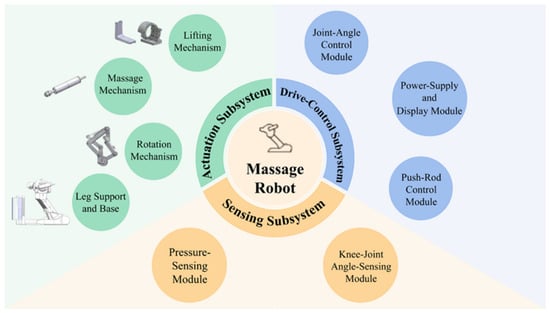
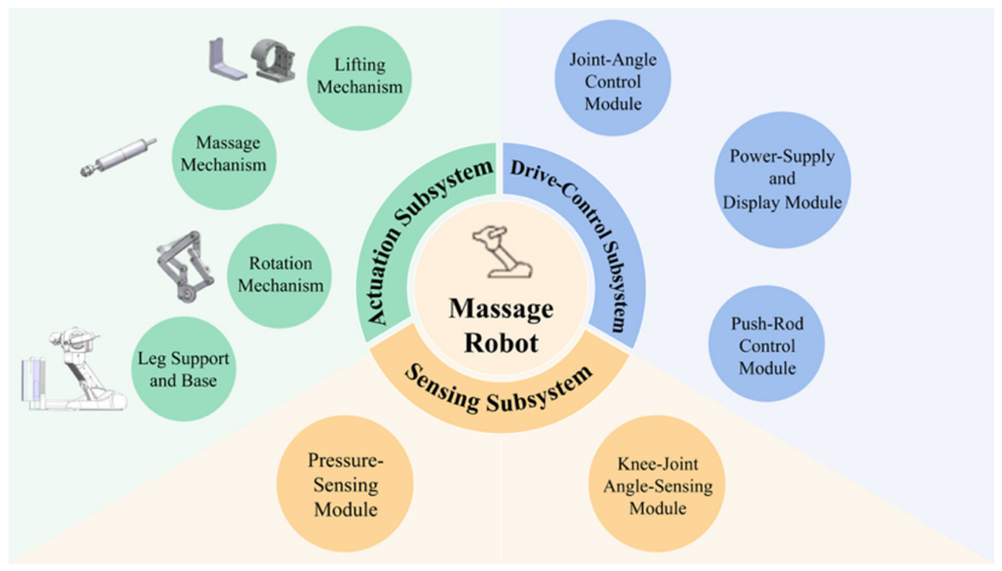
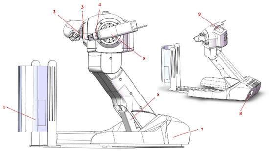
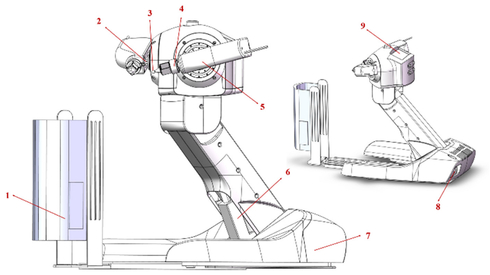
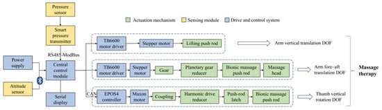
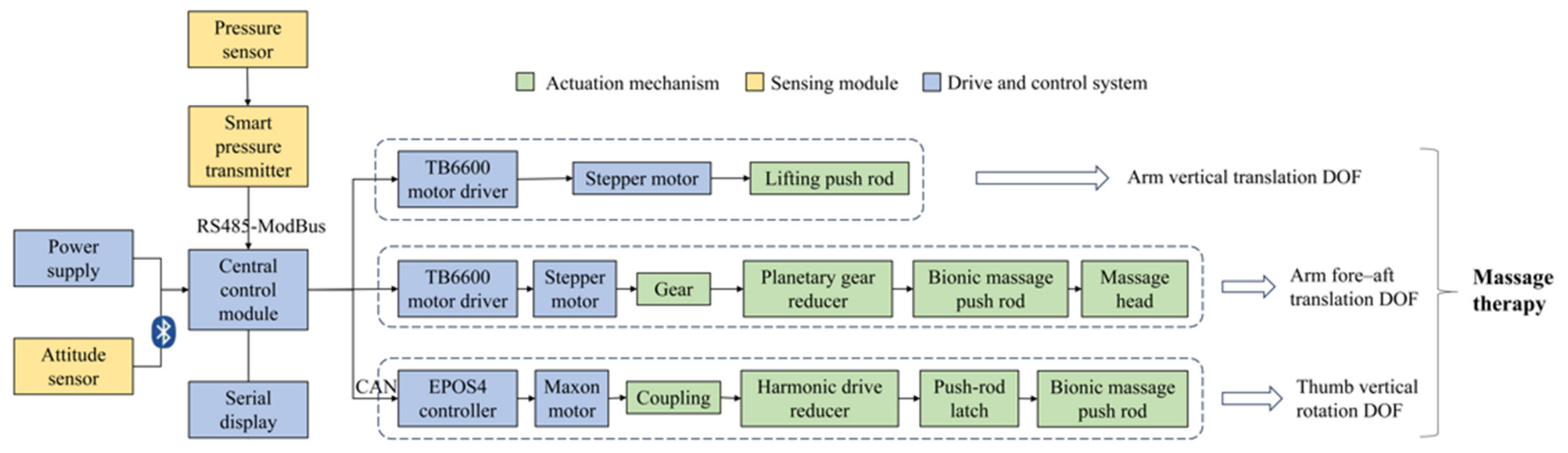
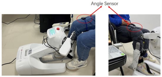
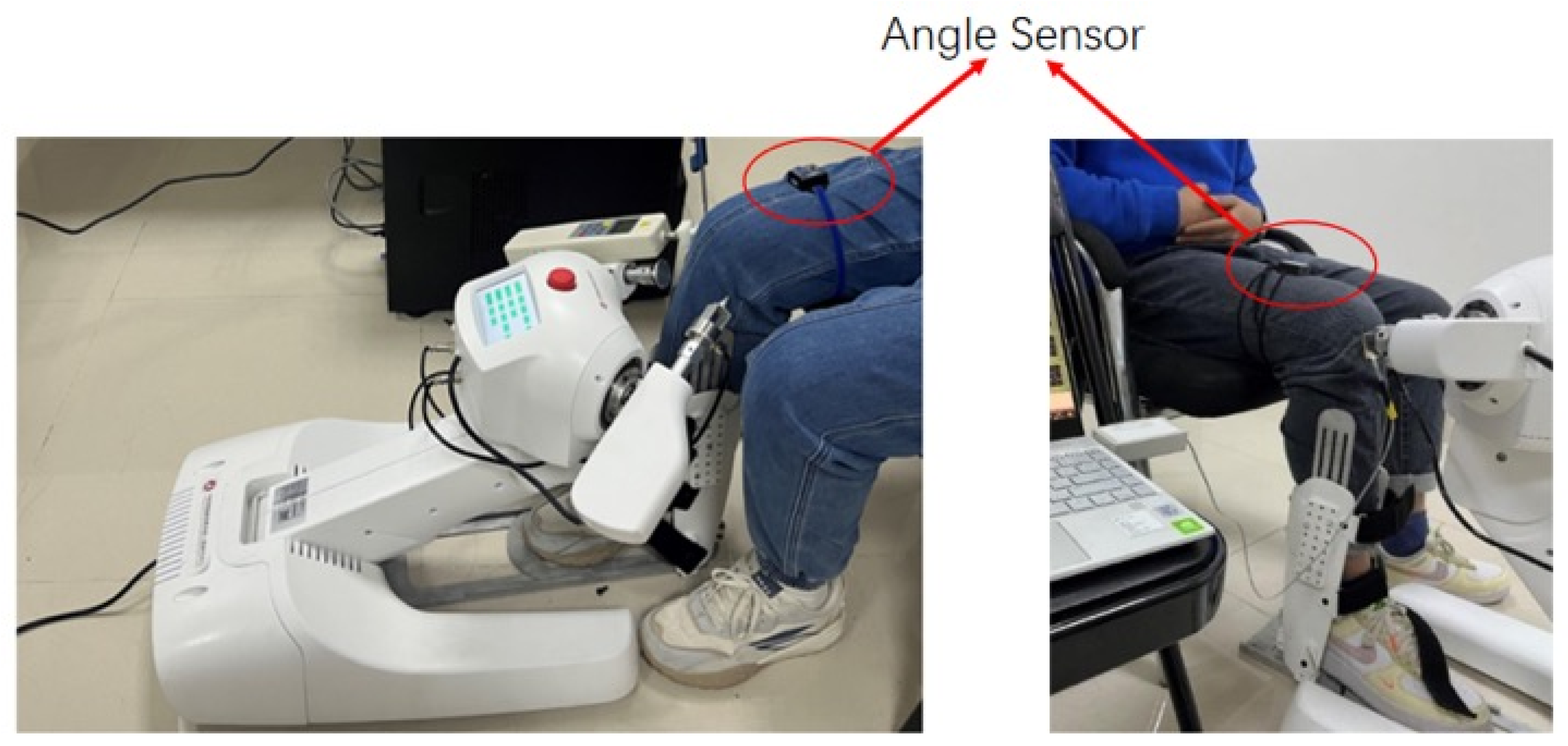
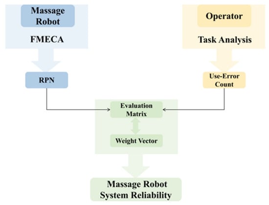
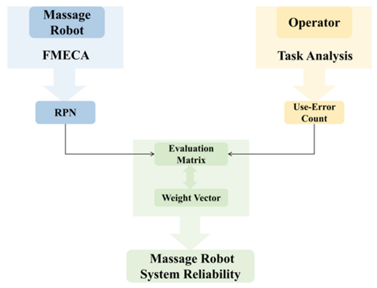

Disclaimer/Publisher’s Note: The statements, opinions and data contained in all publications are solely those of the individual author(s) and contributor(s) and not of MDPI and/or the editor(s). MDPI and/or the editor(s) disclaim responsibility for any injury to people or property resulting from any ideas, methods, instructions or products referred to in the content. |
© 2026 by the authors. Licensee MDPI, Basel, Switzerland. This article is an open access article distributed under the terms and conditions of the Creative Commons Attribution (CC BY) license.