


Abstract
Industrial automation systems operating within geometrically constrained manufacturing environments require engineering approaches capable of integrating functional requirements, mechanical design, numerical verification, and industrial implementation within a traceable development process. This study proposes and empirically evaluates a requirements-driven engineering framework through the development of a three-axis Cartesian manipulator for the automated simultaneous extraction of four injection-moulded runners. The framework extends beyond the sequential application of established engineering tools by introducing a requirements-to-evidence structure in which measurable industrial requirements govern architecture selection and detailed design, while numerical predictions, controlled experiments, and extended industrial monitoring provide backward verification of requirement compliance. Finite element analysis predicted a global maximum displacement of 0.4453 mm and a displacement of 0.29–0.33 mm in the functionally critical gripper region. The maximum equivalent von Mises stress was 8.8 MPa, corresponding to a minimum safety factor of 39. Experimental measurement by three-dimensional laser scanning, with a nominal resolution of 0.001 mm, indicated a maximum relative displacement of 0.37 mm in the gripper region. Comparison with the upper numerical prediction resulted in an absolute difference of 0.04 mm and a relative deviation of 10.8% with respect to the experimental value. Both the numerical and experimental displacements remained below the prescribed functional limit of 1.0 mm. A controlled validation campaign comprising 1000 consecutive operating cycles showed maximum axis-position deviations of 0.8, 0.7, and 0.5 mm along the X-, Y-, and Z-axes, respectively, within the specified ±2.0 mm requirement, while successful runner extraction was achieved in 99.6% of the cycles. Extended monitoring under regular production conditions covered 38,690 cycles over three months, during which the system achieved 99.1% operational availability, with no recorded collisions or operator safety incidents. These results demonstrate the practical applicability of the proposed framework under the investigated industrial conditions and provide traceable evidence linking initial requirements, engineering decisions, numerical predictions, experimental measurements, and long-term operational performance.
1. Introduction
The automotive industry operates within a highly demanding manufacturing environment shaped by global competition, shorter product life cycles, product diversification, strict quality requirements, and sustained pressure on production costs [1,2,3,4]. The sector has consequently become an important driver of advanced production technologies, integrated manufacturing systems, and organizational innovation [5,6,7,8]. Competitiveness increasingly depends on the simultaneous achievement of productivity, quality, flexibility, operational reliability, and environmental performance rather than on production capacity alone [9,10,11,12].
Industrial automation plays a central role in this transition by reducing process variability, stabilizing production cycles, improving quality, and limiting repetitive operator intervention. Application-specific automation has generated measurable benefits in assembly, inspection, packaging, over-injection support, machining, and quality-control operations [13,14,15,16,17,18]. Nevertheless, successful implementation depends on more than replacing manual labour. Automation solutions must simultaneously address manufacturability, equipment compatibility, system integration, maintainability, implementation constraints, and operational performance under real production conditions [19,20,21,22].
The development of such systems is increasingly influenced by digitally integrated manufacturing. Industry 4.0 approaches connect physical automation with sensing, cyber-physical architectures, autonomous quality management, material-flow optimization, and organizational learning [23,24,25,26,27]. Industry 5.0 further extends this perspective by emphasizing human-centricity, sustainability, resilience, and the coevolution of human and technological capabilities [28,29,30,31]. These principles are particularly relevant to repetitive handling operations performed near active production equipment, where automation must improve process performance while reducing undesirable ergonomic and safety exposure.
Material handling represents a critical automation domain because loading, unloading, positioning, extraction, transfer, inspection, and sorting operations can strongly influence cycle stability despite not directly transforming the product. Industrial applications have demonstrated the importance of integrating handling, welding, inspection, injection support, material-flow management, and wire-harness assembly into the broader production system [32,33,34,35]. Injection moulding provides a representative example: although the primary moulding process is highly automated, runner extraction and separation may remain dependent on manual intervention, creating variability and an automation discontinuity within the production cell.
Several robotic architectures may be considered for these operations. Cartesian manipulators are particularly suitable when the required trajectory consists predominantly of orthogonal translations and when workspace compatibility, direct structural load paths, stiffness, positioning repeatability, and mechanical simplicity are decisive [36,37]. However, architecture selection must also account for modularity, standardized automation components, adaptability, integration effort, maintainability, and future reconfiguration [38,39,40,41,42]. A technically feasible manipulator may remain industrially unsuitable if its workspace, cycle time, structural deformation, installation requirements, or maintenance burden are incompatible with the production environment.
Recent research therefore advocates systematic engineering methods that connect robot definition, virtual development, simulation, and implementation. Structured robotic-system development, simulation-based adaptability, knowledge-driven design, modular process orchestration, and flexible automation architectures demonstrate a transition from isolated component design towards model-supported and decision-oriented development [43,44,45,46,47,48]. These studies show that engineering tools should not be applied as independent project stages; instead, their outputs should remain consistent with system requirements and support verification throughout the development process.
More recent methodological developments reinforce this position. Gu et al. [49] proposed X-SEM, a modelling- and simulation-based systems-engineering methodology that promotes consistency between system architecture, physical-behaviour models, simulation, and verification. Li et al. [50] developed a physical-modelling and reliability-analysis approach for industrial-robot motion smoothness that incorporates dataset variability, demonstrating the importance of uncertainty-aware assessment beyond deterministic nominal performance. Zhang et al. [51] introduced the M2OSS systematic research perspective, organizing robotic-machining error sources and their relationships with modelling, measurement, prediction, and compensation. Although these studies address different robotic systems, they collectively demonstrate the value of structured decomposition, model–evidence consistency, uncertainty awareness, and traceable verification.
Despite these advances, the approaches reviewed above primarily emphasize systems-engineering consistency, simulation-supported development, reliability assessment, error decomposition, or flexible robotic implementation [43,44,45,46,47,48,49,50,51]. Comparatively limited attention has been devoted to an industrially demonstrated workflow that maintains explicit and bidirectional traceability between production requirements, engineering decisions, numerical predictions, experimental measurements, and extended operational evidence. The novelty of the present study does not therefore reside in requirements definition, CAD modelling, finite element analysis, or experimental testing considered individually. Instead, the proposed workflow differs from previously reported design and validation approaches through four interconnected mechanisms: the conversion of production needs into measurable engineering requirements and acceptance thresholds; the use of those requirements as weighted criteria for quantitative architecture selection; forward traceability from each requirement to the corresponding architecture, component, CAD, and structural-design decisions; and backward verification through the mapping of numerical predictions, controlled measurements, and extended industrial data to the original requirements. Rather than treating design and validation as separate or predominantly sequential activities, these mechanisms form a closed requirements-to-evidence structure in which non-compliant or marginal results can be traced to the responsible upstream decision. The workflow is empirically evaluated through the development of a three-axis Cartesian manipulator for the simultaneous extraction of four injection-moulded runners. Its methodological contribution is therefore demonstrated for the investigated manipulator and production environment, while applicability to other automation contexts remains to be established through subsequent multi-case validation.
2. Materials and Methods
2.1. Engineering Design Framework
The development of industrial automation systems requires a structured engineering methodology capable of translating production requirements into technically feasible, mechanically robust, and industrially implementable solutions. Unlike conventional product design approaches that frequently focus on the optimization of individual components, automation system development involves the simultaneous consideration of functional requirements, manufacturing constraints, equipment integration, structural performance, operational reliability, maintainability, and economic feasibility. Consequently, the proposed work adopts a requirements-driven engineering design framework, in which every design decision originates from previously established industrial requirements and is progressively refined through successive engineering stages until a validated mechanical solution is obtained.
The proposed framework follows a systematic engineering workflow that combines conceptual design, functional decomposition, mechanical architecture definition, standardized component selection, three-dimensional computer-aided design (CAD), and finite element structural validation within a unified design process. Rather than considering these activities as independent tasks, the methodology establishes direct interactions between consecutive stages, allowing design decisions to be continuously evaluated against the functional requirements imposed by the manufacturing process. This iterative philosophy reduces development uncertainty while improving design consistency, facilitating the early identification of potential structural or operational limitations before physical implementation.
Operationally, the framework is structured around four decision gates. The requirements gate verifies that the industrial problem has been translated into measurable functional, geometric, temporal, structural, safety, and maintainability criteria. The concept gate evaluates alternative manipulator architectures using common quantitative criteria and weighted scoring anchors. The virtual-verification gate assesses whether the selected architecture satisfies workspace, collision-avoidance, component-integration, stiffness, and strength requirements before manufacturing. The industrial-evidence gate subsequently compares the predicted behaviour with controlled measurements and extended production data. Failure to satisfy a gate requires reconsideration of the corresponding upstream decision, thereby creating a closed verification loop rather than a unidirectional sequence of engineering activities.
The methodology begins with the identification of the industrial problem and the definition of the operational requirements imposed by the production environment. These requirements include workspace limitations, production cycle time, payload capacity, positioning accuracy, accessibility constraints, equipment integration, and operational safety. Based on these specifications, alternative conceptual solutions are generated and comparatively assessed using engineering criteria associated with functionality, manufacturability, mechanical simplicity, reliability, scalability, and expected industrial performance. The selected concept subsequently undergoes detailed mechanical development, during which the manipulator architecture, actuation system, guiding elements, structural components, gripping mechanism, and commercial mechanical subsystems are specified according to the previously established functional requirements.
Following the conceptual and detailed design stages, the complete mechanical assembly is developed in a three-dimensional CAD environment to verify geometric compatibility, workspace coverage, component integration, interference-free operation, and assembly feasibility. Numerical structural validation is then performed using finite element analysis (FEA), allowing the evaluation of equivalent stresses, structural displacements, and safety factors under representative operating conditions. The numerical results provide objective engineering criteria for validating the proposed design and confirming its structural suitability prior to industrial implementation.
Unlike a conventional project-oriented workflow that records design activities primarily in chronological order, the proposed methodology organizes development around auditable requirement–decision–evidence relationships. Its principal output is therefore not only the final manipulator but also a traceability structure showing why an architecture or component was selected, which requirement it addresses, how compliance was predicted, and which experimental or industrial evidence confirms, or limits, that compliance. The methodology is summarized in Figure 1 and subsequently instantiated through the quantitative architecture assessment, structural model, controlled validation campaign, and requirement-compliance analysis. The developed Cartesian manipulator should primarily be interpreted as the industrial case through which the requirements-driven workflow was implemented and evaluated. The framework organizes the progression from requirement definition to numerical, experimental, and operational evidence; however, its effectiveness has been demonstrated only for the manipulator architecture, runner-extraction task, and production environment investigated in this study. The framework may provide a structured basis for comparable engineering projects, but validation in additional applications is required before broader methodological transferability can be established.
Figure 1.
Requirements-driven engineering design framework adopted for the systematic development and structural validation of an industrial Cartesian manipulator.
2.2. Industrial Problem Definition
The industrial case investigated in this work concerns the automation of a plastic injection workstation dedicated to the manufacture of automotive control-cable components. The production cell operates with a multi-cavity mould that simultaneously produces finished components together with four injection runners (“gates”), which must be removed immediately after mould opening before the following production cycle can begin. Although the injection process itself is fully automated, the runner extraction operation remained dependent on manual intervention, creating an inconsistency within an otherwise highly automated manufacturing environment.
The existing production process presented several engineering limitations. After mould opening, the operator was required to manually access the rear region of the injection machine, simultaneously grasp the four runners, remove them from the mould area, and deposit them into a dedicated collection container. This operation had to be completed within the limited time available before the subsequent injection cycle started, requiring precise synchronization with the machine sequence. Besides increasing operator workload, the manual operation introduced cycle-time variability and exposed personnel to moving mechanical components operating in a confined workspace.
From an engineering perspective, the automation of this operation cannot be regarded as a simple pick-and-place application. The available installation volume is severely constrained by the geometry of the injection machine, the limited accessibility at its rear side, and the presence of an overhead crane that restricts the allowable manipulator height. Consequently, the mechanical solution must be specifically designed to operate inside a narrow three-dimensional workspace while avoiding interference with the mould, auxiliary equipment and surrounding infrastructure.
Another critical requirement concerns process timing. The manipulator must enter the mould area immediately after opening, simultaneously grip the four runners, withdraw them completely from the machine envelope, release them into the collection container, and return to its standby position before the next production cycle begins. Any delay directly affects machine availability and overall production throughput. Therefore, cycle time becomes one of the primary design constraints governing both the mechanical architecture and motion planning strategy.
Mechanical performance also represents a fundamental design challenge. Because the gripper is positioned at the end of a relatively long cantilevered structure, excessive structural deflection could compromise gripping accuracy and positioning repeatability. The manipulator must therefore combine high stiffness with low moving inertia, ensuring adequate dynamic behaviour while maintaining dimensional precision throughout repeated industrial operation. These requirements justify the subsequent finite element structural assessment performed during the engineering design process.
Economic considerations additionally influenced the engineering strategy adopted in this work. Rather than selecting a commercial Cartesian robot, the industrial partner aimed to develop a customised solution capable of integrating existing standard mechanical components available in the factory inventory. Such an approach reduces investment costs while enabling complete adaptation of the equipment to the specific production cell, including workspace limitations, payload requirements, machine interfaces and maintenance practices.
Consequently, the engineering problem addressed in this study can be formulated as the design and validation of a compact industrial Cartesian manipulator capable of automatically extracting four injection runners from a multi-cavity mould under severe geometric, temporal and structural constraints while ensuring reliable operation, high positioning accuracy, operator safety and seamless integration into an existing automotive production line. This industrial challenge constitutes the starting point for the requirements-driven engineering methodology presented in the following sections.
To facilitate the understanding of the industrial case study, the production environment and the principal engineering constraints governing the manipulator development are schematically illustrated in Figure 2. The diagram summarizes the operational scenario that served as the basis for the requirements-driven engineering design methodology proposed in this work.
Figure 2.
Industrial production cell and principal engineering constraints governing the design of the proposed Cartesian manipulator.
The identified operational, geometric and functional constraints establish the engineering requirements that guided the subsequent conceptual design, mechanical architecture definition, component selection and structural validation presented in the following sections.
Based on the industrial scenario described above, the principal design requirements and engineering constraints were systematically identified and consolidated (Scheme 1). These requirements constituted the primary design drivers throughout the development and validation of the proposed Cartesian manipulator.
Scheme 1.
Industrial design requirements and engineering constraints governing the development of the proposed Cartesian manipulator.
2.3. Functional Requirements
The industrial problem presented in Section 2.2 was translated into a structured set of functional requirements that governed every stage of the engineering design process. Rather than selecting mechanical components at an early stage, the proposed methodology first established the operational functions that the Cartesian manipulator should accomplish under real production conditions. This requirements-driven approach ensured that all subsequent design decisions remained directly connected to industrial needs rather than to predefined hardware solutions.
The requirements were not defined as generic design objectives but were derived from four traceable sources: the injection-machine operating sequence, direct measurements of the available installation envelope, functional constraints associated with runner gripping and extraction, and acceptance targets established by the industrial partner. Process-derived requirements included the available extraction time and the need to remove all four runners before the next production cycle. Geometry-derived requirements included workspace coverage, installation height, collision-free access, and admissible gripper-to-runner misalignment. Component- and structure-derived requirements included payload capacity, moving mass, and elastic displacement. Finally, operational availability, continuous-production capability, machine compatibility, and maintainability were treated as industrial acceptance requirements. The origin and rationale of the principal quantitative targets are clarified below and consolidated in Scheme 2.
Scheme 2.
Functional design specifications established for the development and validation of the proposed Cartesian manipulator.
The primary functional objective was to automate the extraction of the four plastic runners immediately after mould opening while maintaining complete compatibility with the existing injection machine. The manipulator should enter the mould area, simultaneously grasp the four runners, remove them from the machine, deposit them inside the collection container, and return to its initial position before the next production cycle. This complete sequence had to be executed without interfering with the injection process or modifying the existing production layout.
A second fundamental requirement concerned workspace accessibility. Owing to the limited installation volume available at the rear of the injection machine and the presence of an overhead crane, the manipulator had to provide complete coverage of the mould workspace while avoiding collisions with surrounding equipment. Consequently, a three-axis Cartesian architecture was adopted because it provides independent and predictable translational motion while simplifying trajectory planning and structural design.
Cycle time constituted a process-derived requirement. Analysis of the injection-machine operating sequence showed that approximately 2.0 s were available between mould opening and the point at which the manipulator had to be completely withdrawn from the mould area. The vertical approach, simultaneous gripping of the four runners, and initial withdrawal movement therefore had to be completed within . The remaining transfer, release, and return movements were executed during the residual machine-cycle period without extending the injection cycle. The 2.0 s limit was consequently imposed by the existing production process rather than selected as an arbitrary manipulator-performance target.
The positioning requirement was derived from the functional capture envelope between the four gripper jaws and the corresponding runners. The industrial acceptance criterion allowed a maximum positioning deviation of ±2.0 mm at the extraction location while maintaining reliable engagement of all four runners without contact with adjacent mould features. This value represents the overall admissible positioning error, including axis positioning, assembly tolerances, alignment variation, and elastic structural displacement. To prevent structural deformation from consuming the complete positioning-error allowance, a more restrictive limit of 1.0 mm was assigned to elastic displacement at the gripper region. The ±2.0 mm positioning tolerance and the 1.0 mm structural-displacement limit therefore represent different but related acceptance criteria.
The gripping system was required to simultaneously manipulate four runners without damaging either the plastic components or the mould itself. This imposed additional requirements regarding gripping force, repeatability, synchronization between grippers, and positional accuracy. Furthermore, the end-effector had to exhibit low moving mass to minimise inertial loads acting on the vertical axis while preserving rapid dynamic response during repetitive industrial operation. These requirements ultimately motivated the selection of lightweight pneumatic parallel grippers specifically designed for high-cycle industrial automation.
Structural rigidity represented another essential functional requirement. Since positioning errors directly affect gripping reliability, the manipulator structure should minimise elastic deformation under its own weight and operational loads. Simultaneously, the moving structure should remain sufficiently lightweight to reduce actuator effort and improve dynamic response. This compromise between stiffness and mass guided both the structural configuration and the selection of aluminium structural members.
Reliability and maintainability were also incorporated as primary engineering objectives. The manipulator was designed to maximise the use of standard industrial components already available within the company, thereby reducing procurement costs while improving spare-part availability and simplifying maintenance operations. Similarly, pneumatic tubing, electrical wiring and sensor integration were organised to minimise mechanical interference, facilitate inspection and increase long-term operational reliability.
Operational availability was defined as the proportion of scheduled production time during which the manipulator was capable of executing the required automatic extraction cycle. It was calculated from the time records generated during the three-month industrial monitoring period as:
where is the operational availability, is the cumulative time during which the manipulator was scheduled to operate as part of regular production, and is the cumulative manipulator-related downtime recorded within that scheduled period. Downtime duration, rather than the number of interruption events, was used in the calculation. The industrial acceptance target was .
Manipulator-related downtime included the complete interval between the generation of a manipulator or peripheral interlock and restoration of automatic operation. Accordingly, the calculation included the nine low-pneumatic-pressure interruptions, the four limit-switch or axis-referencing interruptions, and the associated diagnostic, pressure-restoration, reset, and re-referencing times. Although these events were preventive rather than uncontrolled mechanical failures, they temporarily prevented the manipulator from executing its required production function and were therefore included in .
Planned non-production periods were excluded from , including scheduled maintenance, mould changes, production changeovers, shift periods during which the cell was not scheduled to operate, and periods without production demand. Unplanned stoppages caused exclusively by the injection-moulding process, mould faults, material supply, upstream or downstream production conditions, or other events external to the manipulator were recorded separately and excluded from . This separation prevented unrelated production-cell downtime from being attributed to the automation system.
The resulting specification therefore established a traceable connection between each engineering target and its originating process, geometric, functional, structural, or industrial constraint. These requirements were subsequently used as architecture-selection criteria, CAD-verification conditions, finite element acceptance limits, and experimental performance indicators. This continuity prevented the targets from being redefined between design and validation and provided the basis for the final requirement-to-evidence assessment.
2.4. Conceptual Design
Following the establishment of the functional design specifications, the next stage of the proposed engineering methodology consisted of identifying a mechanical architecture capable of satisfying the operational, geometric and structural requirements imposed by the industrial application. At this stage, the design process focused on the synthesis of alternative concepts rather than on the selection of individual mechanical components. This approach ensured that the overall system architecture was determined according to functional performance criteria before entering the detailed design phase.
Several conceptual solutions were initially considered for automating the extraction of the injection runners. These alternatives included articulated robotic manipulators, SCARA configurations, gantry systems and Cartesian architectures. Each concept was qualitatively assessed considering the functional specifications established in the previous section, including workspace accessibility, installation constraints, structural rigidity, positioning accuracy, operational simplicity, maintenance requirements, integration with the existing injection moulding machine and expected implementation cost.
Although articulated robotic systems provide high flexibility and multiple degrees of freedom, their implementation within the available workspace would introduce unnecessary kinematic complexity and higher investment costs for a task involving predominantly translational movements. Similarly, SCARA manipulators offer excellent positioning performance for planar assembly operations but present limitations regarding the vertical extraction sequence and the restricted accessibility required inside the mould area. Gantry systems were also evaluated; however, their larger structural dimensions conflicted with the limited installation volume available at the rear of the injection machine.
Based on the engineering requirements identified during the previous stages, a three-axis Cartesian manipulator was selected as the most suitable solution. This architecture provides fully independent linear motion along each axis, facilitating trajectory planning, mechanical control and positioning repeatability while maintaining high structural stiffness and relatively low mechanical complexity. Furthermore, the modular nature of Cartesian systems allows straightforward integration of commercially available linear guides, transmission systems and pneumatic actuators, thereby reducing manufacturing costs and simplifying maintenance operations (Figure 3).
Figure 3.
Concept evaluation and selection framework adopted for the proposed Cartesian manipulator.
The selected concept was subsequently refined through functional decomposition, in which the complete extraction cycle was divided into a sequence of elementary engineering functions. These included vertical positioning, horizontal insertion into the mould, simultaneous gripping of the four runners, controlled extraction, transfer to the collection container, release of the workpieces and return to the initial standby position. Decomposing the overall operation into individual functional blocks simplified both the mechanical architecture definition and the subsequent integration of actuation, guidance and control subsystems. Special attention was given to maintaining design simplicity throughout the conceptual development. The proposed manipulator was therefore configured using only the minimum number of translational degrees of freedom required to accomplish the extraction sequence. This design philosophy reduced the number of moving components, improved structural rigidity, minimised maintenance requirements and increased long-term operational reliability without compromising functional performance.
The evaluation criteria were derived from the functional requirements and industrial constraints established in Scheme 1 and Scheme 2. Workspace compatibility originated from direct measurements of the available production-cell envelope; load-capacity adequacy was defined from the mass of the end-effector and extracted runners; extraction-cycle performance was derived from the mould-opening time window imposed by the injection-moulding machine; and positioning capability was established from the gripper capture envelope required for reliable runner engagement. Structural rigidity was included to limit the elastic contribution to the overall positioning error. Implementation cost, integration effort, maintainability, and mechanical complexity were included as industrialisation criteria because the selected architecture had to be retrofitted to the existing machine using accessible components and without major production-layout modifications.
A five-level scoring scale was adopted to convert heterogeneous technical and industrial indicators into dimensionless ratings. A score of 5 represents full compliance with a substantial performance margin, 4 indicates full compliance with a moderate margin, 3 represents compliance close to the acceptance threshold, 2 indicates marginal or partial compliance requiring corrective measures, and 1 represents non-compliance or an unsuitable solution. Wherever measurable parameters were available, the qualitative descriptors were replaced by the quantitative thresholds reported in Scheme 3. The same scoring direction was used for all criteria, with higher scores consistently representing better performance.
Scheme 3.
Quantitative Criteria and Scoring Anchors Used in the Architecture-Selection Process.
The weights were assigned according to the criticality of each requirement for successful deployment in the existing production cell. Workspace compatibility, extraction-cycle performance, and implementation cost were assigned the highest weight, 15% each, because failure in any of these criteria would compromise physical installation, production throughput, or economic feasibility. Load capacity, positioning capability, structural rigidity, integration effort, and mechanical complexity were assigned intermediate weights of 10% each. Maintainability was assigned 5% because it influences lifecycle performance but does not determine the immediate technical feasibility of the architecture. The resulting weights sum to 100% and were applied consistently to all candidate solutions.
The comparative assessment demonstrated that the Cartesian architecture provided the best compromise between workspace accessibility, structural rigidity, positioning accuracy, implementation simplicity and industrial feasibility, thereby establishing the foundation for the subsequent detailed mechanical design.
To reduce the subjectivity of the conceptual selection, the candidate architectures were assessed using a weighted decision matrix combining quantitative and engineering criteria (Scheme 3). The quantitative requirements were derived directly from the production-cell constraints and the functional specifications presented in Scheme 1 and Scheme 2. These included coverage of an approximately 1.8 m × 1.6 m working region, compliance with the maximum available installation height of 3.0 m, sufficient capacity for an end-effector mass below 2.0 kg, completion of the extraction movement within 2.0 s, and positioning capability compatible with the prescribed tolerance. Implementation cost was represented by a normalized installed-cost index, , which included the manipulator structure, actuation, controller requirements, peripheral equipment, structural adaptations, programming, and commissioning. The customised Cartesian solution was used as the reference condition, , because it maximised the use of standard components already available within the company. This normalized approach avoids potentially misleading comparisons based only on the purchase price of the robot unit (Scheme 4).
Scheme 4.
Comparative assessment of alternative manipulator architectures.
Each architecture was rated from 1 to 5 using predefined scoring anchors rather than unrestricted qualitative judgement. For workspace compatibility, the score reflected the proportion of the required operating region that could be reached without collision and without exceeding the installation envelope. For load capacity, the score reflected the available payload margin relative to the design load. Cycle-time performance was evaluated against the 2.0 s extraction requirement, while cost was evaluated from the normalized installed-cost index. Positioning accuracy, structural rigidity, integration effort, maintainability, and mechanical complexity were evaluated using the same requirements-driven approach. The final score was calculated as:
where is the weighted score of architecture , is the normalized weight assigned to criterion , and is the rating of architecture for criterion . The criterion weights sum to unity.
The criterion weights were normalized before application to the decision matrix according to:
where is the initially assigned importance of criterion , and is its normalized weight. Because every criterion was rated on a five-level scale, the overall normalized compliance of architecture was calculated as:
where is the normalized architecture-compliance percentage. Accordingly, the Cartesian architecture score of 4.90 corresponded to .
- Workspace compatibilitywhere is the required operating region and is the collision-free region reachable by architecture . The score anchors in Scheme 3 were assigned from the resulting workspace-coverage percentage, provided that the 3.0 m installation-height constraint was also satisfied.
- Load-capacity adequacywhere is the available payload of architecture and is the prescribed design load. Values indicated that the architecture did not satisfy the payload requirement.
- Normalized installed cost
The installed cost included the mechanical structure, actuation, controller, peripheral equipment, production-cell adaptations, programming, installation, and commissioning. The customized Cartesian solution was adopted as the reference condition, .
An architecture was eligible for final selection only when it satisfied the mandatory workspace, installation-height, payload, collision-avoidance, and extraction-time constraints. The weighted score was therefore used to rank feasible architectures and was not permitted to compensate for failure to satisfy a mandatory condition.
Using the quantitative thresholds and scoring anchors defined above, the four candidate architectures were comparatively evaluated through a weighted decision matrix. The weights reflect the relative importance of the industrial constraints, with particular emphasis on workspace compatibility, extraction-cycle performance, and implementation cost. Each cell reports the assigned rating followed, in parentheses, by its weighted contribution to the final score.
The Cartesian manipulator achieved a weighted score of 4.90 out of 5.00, corresponding to 98% normalized compliance with the established requirements. Its selection was mainly supported by complete coverage of the required workspace, compatibility with the 2.0 s extraction-time constraint, high positioning capability, structural rigidity, direct integration with the existing production cell, and the lowest normalized implementation cost. Although the articulated, SCARA, and gantry alternatives provided sufficient payload capacity, this capability did not compensate for their lower workspace compatibility, greater integration burden, or higher implementation complexity. The results therefore confirm that the Cartesian architecture offered the most balanced application-specific solution rather than merely the highest general-purpose robotic capability.
Because weighting schemes may introduce decision-maker dependence, a sensitivity analysis was performed to assess whether the selected architecture remained stable under alternative prioritisation assumptions (Scheme 5). Five deterministic weighting scenarios were considered: the baseline scheme, equal weighting, productivity priority, cost and integration priority, and technical-performance priority. In addition, a one-at-a-time analysis was conducted by varying each baseline weight by ±25%, followed by normalization of the complete weight vector to preserve a total of 100%. The architecture scores were recalculated without changing the criterion ratings.
Scheme 5.
Sensitivity Analysis of the Architecture-Selection Weighting Scheme.
The sensitivity results demonstrate that the architecture ranking is not dependent on a narrowly defined weighting scheme. The Cartesian manipulator remained the highest-ranked alternative in every deterministic scenario and throughout all one-at-a-time weight perturbations. Its minimum advantage over the second-ranked architecture was 1.10 points among the alternative weighting scenarios and 1.195 points under the ±25% perturbation analysis. The selection is therefore robust to reasonable changes in criterion importance and does not result solely from the baseline weighting assumptions.
2.5. Mechanical Architecture
Following the conceptual selection of the Cartesian configuration, the proposed manipulator was developed as a modular three-axis mechanical system specifically designed to satisfy the functional requirements established in the previous sections. The architecture was conceived to provide complete workspace accessibility while maintaining high structural rigidity, compact dimensions and straightforward integration with the existing injection moulding workstation. The complete mechanical assembly was organised according to a hierarchical design philosophy, in which the supporting frame, linear motion systems, end-effector assembly and auxiliary subsystems were progressively integrated into a unified engineering solution.
The structural frame constitutes the primary load-bearing element of the manipulator and was designed to provide sufficient stiffness while minimizing overall mass. Aluminium structural profiles were selected owing to their favourable stiffness-to-weight ratio, corrosion resistance and ease of assembly using standardized industrial fastening systems. This modular construction also facilitates future modifications, maintenance interventions and replacement of individual structural elements without requiring redesign of the complete system.
Manipulator motion is achieved through three independent orthogonal translational axes corresponding to the X-, Y- and Z-directions. This arrangement enables fully decoupled positioning, considerably simplifying trajectory generation and control while ensuring accurate access to the mould cavity. The horizontal axes provide positioning inside the machine workspace, whereas the vertical axis performs the insertion and withdrawal movements required during the gripping operation. Such kinematic simplicity significantly reduces control complexity compared with articulated robotic systems while maintaining the positioning accuracy required for repetitive industrial operation.
The end-effector assembly was specifically developed for the simultaneous handling of four injection runners produced during each moulding cycle. Rather than employing a conventional single gripping device, the proposed solution incorporates four synchronized pneumatic grippers mounted on a dedicated support plate, thereby allowing all runners to be extracted in a single operation. The gripper arrangement was geometrically optimized according to the cavity distribution of the injection mould, ensuring stable gripping while preventing interference with adjacent mould components during insertion and extraction.
Special consideration was also given to the integration of auxiliary mechanical and pneumatic subsystems. Pneumatic fittings, position sensors, cable routing and cable carrier systems were incorporated directly into the CAD assembly to ensure collision-free operation throughout the complete manipulator workspace. This integrated design approach simplified installation, improved accessibility during maintenance operations and reduced the likelihood of cable fatigue or accidental interference with moving components during continuous industrial operation.
The resulting mechanical architecture combines structural simplicity with high functional capability, providing a compact automation solution specifically adapted to the geometric restrictions of the production cell. Furthermore, the modular organisation adopted during the mechanical design stage facilitates the subsequent selection of standardized industrial components and enables independent optimisation of each subsystem without compromising the overall structural integrity of the manipulator. This architecture therefore establishes the engineering foundation for the detailed component specification presented in the following section.
Following the conceptual selection of the Cartesian configuration, the manipulator was developed as an integrated mechanical system comprising the structural frame, linear motion subsystems, actuation elements and end-effector assembly. The overall architecture of the proposed solution is illustrated in Figure 4.
Figure 4.
Mechanical architecture of the proposed three-axis Cartesian manipulator and its main functional subsystems.
The integrated mechanical architecture provides the structural and functional basis required to ensure accurate positioning, reliable runner extraction and seamless integration with the existing injection moulding workstation, thereby supporting the subsequent detailed component specification and structural validation.
To complement the mechanical architecture presented in Figure 4, the principal subsystems of the proposed manipulator were systematically identified together with their corresponding engineering functions (Scheme 6). This decomposition clarifies the contribution of each component to the overall operational performance of the system.
Scheme 6.
Main mechanical components and engineering functions of the proposed Cartesian manipulator.
The functional decomposition of the mechanical architecture demonstrates that each subsystem was selected to satisfy specific operational requirements while contributing to the overall stiffness, positioning accuracy, reliability and maintainability of the proposed industrial manipulator.
2.6. Component Selection
Following the definition of the mechanical architecture, the detailed engineering design focused on the systematic selection of the principal mechanical, actuation and auxiliary components required for the implementation of the proposed Cartesian manipulator. Component selection was performed according to a requirements-driven methodology in which every element was evaluated considering its contribution to positioning accuracy, structural rigidity, operational reliability, maintainability and compatibility with the industrial production environment.
The structural subsystem was developed using modular aluminium profile elements owing to their favourable stiffness-to-weight ratio, corrosion resistance and ease of assembly. The use of standardized structural profiles also simplified manufacturing, reduced machining requirements and facilitated future modifications or maintenance interventions. This modular philosophy ensured sufficient structural rigidity while maintaining the lightweight characteristics required for rapid dynamic operation.
Linear motion was implemented through precision linear guide systems installed on the three translational axes. These guides were selected to guarantee smooth displacement, high repeatability and low friction throughout the manipulator workspace. Their load-carrying capacity and rigidity ensured accurate positioning during repetitive industrial cycles while minimizing deflection under operational loading conditions.
Different transmission systems were adopted according to the functional requirements of each motion axis. Belt-driven transmissions were selected for the horizontal axes because of their high travelling speed, mechanical simplicity and reduced inertia, making them particularly suitable for long-stroke positioning movements. Conversely, the vertical axis employed a ball-screw transmission to provide higher axial stiffness, superior positioning precision and secure load support during insertion and extraction operations. This hybrid transmission strategy represented an effective compromise between dynamic performance and positioning accuracy.
Motion actuation was achieved through independent servomotor drives installed on each translational axis. The selection of servomotors was based on the required positioning accuracy, acceleration capability and continuous operating reliability. Independent axis control also simplified trajectory generation and facilitated future integration with industrial motion controllers and programmable logic controllers (PLCs).
The gripping subsystem incorporated four synchronized pneumatic parallel grippers mounted on a custom-designed support plate. Pneumatic actuation was selected because of its fast response, mechanical robustness and industrial reliability under repetitive production cycles. The custom support plate ensured accurate alignment between the grippers and the injection mould cavity geometry, enabling simultaneous extraction of the four runners while preventing mechanical interference during insertion and withdrawal.
Position monitoring and reference detection were implemented using industrial proximity sensors distributed along the motion axes. These sensors provided homing functions, end-of-travel detection and operational safety while ensuring repeatable positioning throughout successive production cycles. Pneumatic valves, tubing and cable carrier systems were simultaneously integrated into the mechanical design to guarantee reliable routing of electrical and pneumatic connections while preventing cable fatigue or collision with moving elements.
An additional criterion during component selection was the extensive use of commercially available industrial components already employed within the company. This strategy reduced procurement costs, simplified spare-part management and facilitated future maintenance activities while increasing the practical applicability of the proposed manipulator in an industrial environment.
Overall, the adopted component selection methodology ensured that every subsystem satisfied the functional, structural and operational requirements previously established. Consequently, the final engineering solution combined mechanical simplicity, high positioning performance, ease of maintenance and industrial robustness, providing a solid basis for the structural verification and experimental validation presented in the subsequent sections.
Component selection was performed using a structured engineering workflow in which the functional requirements, mechanical architecture and performance criteria were systematically translated into the selection of commercially available industrial components. The adopted methodology is summarized in Figure 5.
Figure 5.
Engineering component selection workflow adopted for the proposed Cartesian manipulator.
The proposed workflow ensured that every selected component satisfied the established functional, structural and operational requirements while promoting system reliability, ease of integration, maintainability and industrial feasibility.
Following the component selection workflow, the principal mechanical and auxiliary elements were selected according to their functional performance, industrial availability and compatibility with the proposed manipulator architecture. The selected components and their engineering justification are summarized in Scheme 7.
Scheme 7.
Selected components and engineering justification for the proposed Cartesian manipulator.
The selected components collectively provide an optimal balance between positioning accuracy, structural rigidity, operational reliability, maintainability and cost-effectiveness, ensuring the successful implementation of the proposed industrial manipulator.
2.7. CAD Development
The detailed engineering design of the proposed Cartesian manipulator was carried out using a three-dimensional parametric Computer-Aided Design (CAD) approach. The digital model served not only as a geometric representation of the final system but also as the primary engineering environment for evaluating structural integration, workspace accessibility, component compatibility and assembly feasibility before manufacturing.
The CAD development followed a hierarchical modelling strategy in which the manipulator was progressively constructed from individual components to complete functional assemblies. Initially, the structural frame was modelled to establish the global reference geometry and the installation boundaries imposed by the injection moulding machine. Subsequently, the three translational axes, transmission systems, servomotors and end-effector assembly were sequentially incorporated into the digital model, allowing continuous verification of geometric compatibility throughout the design process.
Particular attention was devoted to collision detection and workspace validation. The complete operating envelope of the manipulator was analysed to verify that all programmed movements could be executed without interference with the injection mould, surrounding equipment or structural elements of the manipulator itself. This virtual verification significantly reduced implementation risks while ensuring complete accessibility to the mould cavity during the runner extraction cycle.
The CAD environment also supported the optimisation of component positioning and subsystem integration. Pneumatic tubing, electrical wiring, proximity sensors and cable carrier systems were incorporated directly into the digital assembly to minimise routing complexity and prevent interference with moving components. This integrated modelling approach facilitated future assembly operations while improving maintainability and accessibility for inspection and servicing.
The final digital prototype provided a complete virtual representation of the proposed manipulator and established the basis for subsequent structural verification, manufacturing documentation and experimental implementation. Consequently, the CAD development stage considerably reduced engineering uncertainty while accelerating the transition from conceptual design to industrial realization.
The development of the proposed manipulator was supported by a comprehensive CAD-based engineering workflow, enabling the progressive integration of mechanical subsystems and the virtual verification of assembly, workspace accessibility and operational feasibility prior to manufacturing. The adopted digital development methodology is illustrated in Figure 6.
Figure 6.
Digital CAD development and virtual validation workflow adopted during the engineering design of the proposed Cartesian manipulator.
The virtual development workflow significantly reduced design uncertainty by enabling early verification of geometric compatibility, collision-free operation and subsystem integration, thereby improving the robustness and manufacturability of the final engineering solution.
2.8. Finite Element Methodology
Before prototype manufacturing, the structural response of the Cartesian manipulator was evaluated through a three-dimensional static finite element analysis. The purpose of the analysis was to verify that the complete load-bearing architecture satisfied the prescribed stiffness and strength requirements under the most demanding operating configuration. The numerical model was generated directly from the final CAD assembly and included the aluminium structural frame, mounting brackets, axis-support members, carriages, linear-guide interfaces, vertical-axis assembly, and end-effector support. Small secondary components whose contribution to global stiffness was negligible, including fasteners, pneumatic tubes, electrical cables, sensors, and protective covers, were excluded to reduce computational cost. The complete assembly was discretised using a solid tetrahedral mesh generated through the Blended curvature-based algorithm. Second-order parabolic tetrahedral elements, evaluated at 16 Jacobian points, were adopted to improve the representation of the structural response under bending. The element size varied between 4.92 and 98.34 mm, resulting in 61,639 elements and 115,283 nodes. The adopted mesh was not selected through a formal multi-level mesh-convergence study and, consequently, no percentage-change convergence tolerance was applied. Mesh adequacy was instead assessed through curvature-based local refinement, element-density distribution, aspect-ratio indicators, and the concentration of smaller elements in geometrically complex and load-transfer regions. The numerical results should therefore be interpreted as engineering verification based on the reported mesh rather than as a formally demonstrated mesh-independent solution.
The analysis assumed linear-elastic, homogeneous, and isotropic material behaviour. This assumption was considered appropriate because the calculated stresses remained below the yield strength of the constituent materials and no permanent deformation was expected under normal operation. For transparency and reproducibility, the complete numerical-model definition is consolidated in Scheme 8, including the assigned materials, boundary conditions, applied loads, contact formulation, element characteristics, mesh-quality indicators, acceptance criterion, and principal numerical results. All component interfaces included in the structural model were represented using a global bonded-contact formulation, which prevented relative sliding or separation between connected parts. The bolted attachment of the manipulator base to the injection-moulding machine was represented by fixed constraints applied to the corresponding mounting surfaces. Linear guides and carriages were represented through their external structural interfaces, while the detailed internal geometry of the recirculating rolling elements, preload mechanisms, and fasteners was omitted.
Scheme 8.
Finite Element Model Definition and Simulation Parameters.
The boundary conditions reproduced the actual installation of the manipulator in the industrial workstation. The surfaces corresponding to the bolted attachment of the manipulator base to the injection-moulding machine were fully constrained against translation and rotation. Gravitational acceleration was applied to the complete assembly in its actual installation direction. The gravitational force associated with each represented component or lumped mass was calculated as:
where is the gravitational force, is the component mass, and is gravitational acceleration. Accordingly, each 1.1 kg pulley generated a vertical load of approximately 10.8 N, the 2.5 kg servomotor generated a vertical load of approximately 24.5 N, and the 0.939 kg end-effector assembly—including the mounting blocks, pneumatic grippers, fittings, sensors, jaws, and four handled runners—was represented by a distributed vertical load of approximately 9.21 N.
In addition to the gravitational loads, the torque transmitted through the pulley system was converted into an equivalent tangential force acting on the supporting structure. This force was determined from the torque–radius relationship:
where is the equivalent tangential force, is the transmitted torque, and is the pulley pitch radius. Using and , the corresponding tangential load was:
This load was applied at the pulley interfaces in the direction corresponding to the transmission force. The combined loading condition therefore included self-weight, the moving-axis components, the servomotor, the end-effector assembly, the handled runners, and the tangential pulley force.
The critical service condition corresponded to the manipulator configuration producing the highest bending moment at the vertical-axis support. The horizontal axes were positioned at their maximum operational extension, placing the moving masses and end-effector at the largest relevant distance from the supporting structure. This configuration was selected because it simultaneously maximized the gravitational bending contribution and the structural effect of the pulley-transmitted load. It therefore represented the most conservative static operating condition within the validated workspace. The applied loads, material properties, contact assumptions, boundary conditions, and mesh characteristics are consolidated in Scheme 8.
Structural strength was evaluated by comparing the maximum equivalent von Mises stress with the yield strength of the governing structural material. The minimum numerical safety factor was calculated as:
where is the material yield strength and is the maximum equivalent von Mises stress predicted by the finite element model. For aluminium 2024-T3, , while the maximum predicted equivalent stress was . The resulting minimum safety factor was therefore:
The design was considered structurally compliant when .
Because successful runner gripping depends primarily on positional stability at the end-effector, structural stiffness was assessed using the displacement predicted in the gripper-support region. The utilization of the allowable displacement was calculated as:
where is the percentage utilization of the displacement allowance, is the maximum predicted displacement in the functionally critical gripper region, and is the admissible displacement limit. Using the upper numerical displacement of 0.33 mm and the functional limit of 1.0 mm, the displacement utilization was:
The corresponding remaining functional stiffness margin was therefore 67%. The global maximum displacement of 0.4453 mm occurred at the upper region of the Z-axis electric actuator, whereas the displacement in the gripper region varied between 0.29 and 0.33 mm. Both results remained below the prescribed 1.0 mm functional limit.
The final mesh comprised 61,639 second-order tetrahedral elements and 115,283 nodes, with element sizes ranging from 4.92 to 98.34 mm. Curvature-based refinement was applied to geometrically complex and load-transfer regions, including carriage connections, guide interfaces, mounting brackets, the vertical-axis support, and the end-effector attachment. Mesh quality was evaluated using the element aspect-ratio distribution and Jacobian-point formulation reported in Scheme 8. Because a formal multi-level mesh-convergence study was not performed, the numerical results should be interpreted as an engineering verification of the adopted model rather than as a mathematically demonstrated mesh-independent solution. This limitation does not affect the transparency of the reported model but defines the appropriate boundary for interpreting the numerical precision.
Prior to manufacturing, the structural performance of the proposed Cartesian manipulator was assessed through a Finite Element Analysis (FEA) methodology. The numerical workflow integrated CAD modelling, mesh generation, structural simulation and engineering verification to evaluate the mechanical integrity of the proposed design before physical implementation. The adopted validation procedure is presented in Figure 7.
Figure 7.
Finite element analysis workflow and structural verification methodology adopted for the proposed Cartesian manipulator.
The integrated FEA workflow enabled the early identification of potential structural limitations while verifying stress distribution, displacement behaviour and overall stiffness, thereby providing numerical confidence for the subsequent manufacturing and experimental validation stages.
The numerical model therefore reproduces the physical support condition and the principal gravitational and transmission-induced loads acting on the manipulator. Under these conditions, the maximum total displacement was 0.4453 mm, while the displacement at the functionally critical gripper region remained between 0.29 and 0.33 mm, below the prescribed limit of 1.0 mm. The maximum equivalent von Mises stress was 8.8 MPa and the minimum safety factor was 39, confirming that structural stiffness, rather than material strength, governed the design.
2.9. Validation Strategy
To ensure the engineering reliability of the proposed Cartesian manipulator, a multi-stage validation strategy was adopted, combining virtual verification, prototype implementation and functional assessment under representative industrial operating conditions. Rather than relying on a single validation procedure, the proposed methodology progressively evaluated the design throughout successive development stages, thereby reducing implementation risks while increasing confidence in the final engineering solution.
The first validation level corresponded to the digital development stage, during which the complete three-dimensional CAD model was used to verify assembly feasibility, subsystem integration and workspace accessibility. Virtual simulations confirmed the absence of geometric interference between moving components, the injection mould and surrounding equipment, ensuring that the proposed manipulator could execute the complete operational sequence within the available installation volume.
The second validation level consisted of structural verification through Finite Element Analysis. Numerical simulations were performed to evaluate stress distribution, structural deformation and overall stiffness under representative service loads. The finite element results confirmed that the mechanical structure satisfied the established design criteria, providing sufficient rigidity and maintaining stresses within the allowable limits of the selected materials. Consequently, the numerical analyses validated the structural integrity of the proposed design before prototype manufacturing.
Following the virtual validation stages, the manipulator was manufactured and assembled using the selected industrial components. Mechanical integration included the installation of the structural frame, linear motion systems, transmission mechanisms, servomotors, pneumatic grippers, sensors and auxiliary subsystems according to the validated CAD model. Particular attention was devoted to preserving the dimensional accuracy and alignment previously verified during the digital development phase.
The final validation stage comprised functional testing under representative production conditions. The complete operating sequence—including mould access, simultaneous gripping of the four runners, extraction, transfer to the collection container and return to the home position—was experimentally evaluated to verify positioning repeatability, operational reliability and compatibility with the production cycle. These tests confirmed the practical feasibility of the proposed engineering solution and demonstrated its successful integration into the industrial injection moulding workstation.
Overall, the adopted validation strategy established a continuous verification process extending from conceptual design to prototype implementation. By integrating digital modelling, numerical simulation and experimental validation within a unified engineering methodology, the proposed approach significantly reduced development uncertainty while increasing the technical robustness and industrial applicability of the final Cartesian manipulator.
To ensure the technical robustness of the proposed solution, a comprehensive validation strategy was implemented throughout the engineering design process. The methodology combined digital verification, numerical simulation, prototype implementation and experimental assessment, providing progressive evidence of the manipulator’s structural integrity and operational feasibility. The overall validation strategy is summarized in Figure 8.
Figure 8.
Integrated engineering validation strategy adopted for the development and verification of the proposed Cartesian manipulator.
2.10. Engineering Workflow Summary
The engineering methodology adopted in this work followed a structured requirements-driven design philosophy, integrating industrial problem identification, functional specification, conceptual development, mechanical architecture definition, systematic component selection, CAD-based virtual prototyping, finite element verification and experimental validation. Rather than treating these activities as isolated tasks, the proposed workflow established a continuous engineering process in which each development stage directly supported the subsequent design decisions. Figure 9 summarizes the methodology as implemented and evaluated in the specific industrial case considered.
Figure 9.
Integrated engineering design methodology adopted for the development and validation of the proposed Cartesian manipulator.
The proposed engineering methodology establishes a coherent and reproducible design framework that integrates requirements engineering, mechanical design, numerical verification and experimental validation into a unified development process. This systematic approach not only ensured the successful implementation of the proposed manipulator but also provides a potentially reusable methodology for the development of similar industrial automation systems operating under constrained manufacturing environments.
3. Results and Discussion
3.1. Mechanical Design Outcomes and Discussion
The proposed engineering methodology resulted in the successful development of a three-axis Cartesian manipulator specifically designed for the automated extraction of injection runners under the geometric and operational constraints imposed by the industrial production cell [8,11,16,22]. The final mechanical solution integrates a modular structural frame, three orthogonal translational axes, an optimized end-effector assembly and standardized industrial components into a compact automation system capable of performing the complete extraction cycle without requiring modifications to the existing injection moulding workstation [13,19,26,35]. To provide a concise overview of the developed system, the principal mechanical characteristics and technical specifications of the proposed Cartesian manipulator are summarized in Scheme 9. These parameters represent the final engineering solution resulting from the adopted design methodology.
Scheme 9.
Mechanical design characteristics of the proposed Cartesian manipulator.
One of the principal achievements of the mechanical design was the successful integration of all functional subsystems within the restricted installation envelope available at the rear of the injection machine. Despite the limited workspace and the presence of surrounding equipment, the proposed architecture provides complete accessibility to the mould cavity while maintaining collision-free operation throughout the entire extraction sequence. This result demonstrates the effectiveness of the requirements-driven design methodology adopted during the conceptual and detailed engineering stages [7,15,24,35,48].
The modular structural configuration also constitutes an important engineering outcome. The use of standardized aluminium profiles, precision linear guidance systems and commercially available transmission components produced a lightweight yet mechanically robust structure capable of supporting the required operational loads while maintaining high positioning stability [14,27,33,46]. Furthermore, the modular organisation of the manipulator considerably simplifies future maintenance operations, subsystem replacement and possible adaptation to different mould geometries or production layouts [12,18,28,50,51].
Another significant design outcome concerns the end-effector assembly. Instead of extracting each runner individually, the developed manipulator simultaneously grips the four injection runners using a dedicated multi-gripper arrangement specifically adapted to the mould geometry. This solution considerably simplifies the extraction process, reduces handling time and improves process consistency while minimizing unnecessary manipulator movements during repetitive industrial operation [17,29,38,49].
The complete CAD integration of structural, pneumatic and electrical subsystems also represents an important engineering contribution. Cable routing, pneumatic tubing, proximity sensors and auxiliary components were incorporated directly into the digital assembly, allowing interference-free integration and improving accessibility for inspection and maintenance. This integrated approach reduced implementation uncertainty and facilitated the transition from virtual design to prototype manufacturing [9,26,34,45,52].
Overall, the final mechanical design successfully satisfies the functional requirements established during the engineering specification stage. The resulting manipulator combines compact dimensions, high structural rigidity, modular construction and straightforward industrial integration, providing an effective engineering solution for the automated extraction of injection runners in high-volume plastic injection processes [11,23,31,37,48]. The developed system therefore demonstrates the practical applicability of the proposed design methodology while establishing a robust mechanical platform for the subsequent structural and experimental validation stages [25,32,44,53].
The engineering methodology resulted in the development of a fully integrated three-axis Cartesian manipulator specifically designed to satisfy the functional and operational requirements identified during the design stage. The final mechanical configuration, including its principal structural subsystems and industrial integration, is presented in Figure 10.
Figure 10.
Final mechanical design of the proposed Cartesian manipulator, illustrating the integrated mechanical architecture, principal structural subsystems and industrial implementation for automated runner extraction.
Compared with conventional Cartesian manipulators reported in the literature, the proposed solution was specifically developed under stringent industrial installation constraints rather than as a generic laboratory automation platform. Previous studies have primarily focused on improving positioning accuracy, dynamic performance or payload capacity, whereas the present work simultaneously addresses workspace limitations, mould accessibility, rapid installation and direct industrial integration within an existing injection moulding cell [13,16,26,35]. This application-oriented design philosophy increases the practical relevance of the proposed manipulator while demonstrating the effectiveness of integrating engineering requirements into the earliest stages of the design process.
An additional contribution of the proposed design lies in the complete integration of CAD-based engineering, component selection and numerical verification within a unified development methodology. While many previously published studies present either the mechanical design or the experimental implementation separately, the present work establishes a traceable engineering workflow linking industrial requirements, conceptual development, virtual verification and prototype realization [9,25,34,46,52]. Such an integrated approach considerably reduces development uncertainty and facilitates the transfer of engineering solutions from the digital environment to real manufacturing systems.
The selected mechanical architecture also reflects current engineering trends towards modular, lightweight and easily maintainable industrial automation systems. The extensive use of commercially available components, aluminium structural profiles and standardized transmission systems is consistent with recent developments in industrial robotic design, where flexibility, maintainability and lifecycle cost are increasingly considered alongside conventional performance criteria [18,27,32,45]. Consequently, the proposed solution offers not only satisfactory mechanical performance but also practical advantages for future industrial deployment and system scalability.
3.2. Finite Element Results
The structural behaviour of the proposed Cartesian manipulator was evaluated through finite element simulations in order to verify whether the developed mechanical architecture satisfied the stiffness and strength requirements established during the engineering design stage [25,32,43,46]. The numerical analyses focused on the distribution of equivalent von Mises stresses, global deformation patterns and structural displacement under representative operational loading conditions.
The obtained results indicate that the proposed mechanical architecture exhibits a highly favourable structural response. The highest equivalent stresses were concentrated at localized geometric discontinuities, particularly in the interfaces between the vertical axis assembly, linear guide supports and structural connections. Nevertheless, these stress concentrations remained restricted to relatively small regions and did not compromise the global structural integrity of the manipulator. The remaining structural members experienced substantially lower stress levels, confirming an efficient distribution of mechanical loads throughout the supporting frame [26,32,37,46].
The displacement analysis demonstrated that the overall structure possesses adequate rigidity for precision positioning tasks. As expected, the maximum displacements occurred at the free end of the vertical manipulation assembly, where the operational loads generated the largest bending moments. However, the predicted deformation remained sufficiently small to avoid any significant influence on positioning accuracy or on the repeatability required for simultaneous extraction of the four injection runners [14,27,43,49].
The numerical simulations also confirmed the effectiveness of the adopted structural configuration. The combination of modular aluminium profiles, precision linear guidance systems and appropriately positioned structural supports provided a balanced compromise between lightweight construction and mechanical stiffness. Consequently, no evidence of excessive deformation, local instability or structurally critical regions was identified under the considered service conditions [18,28,33,45,52]. Indeed, the limited structural deformation predicted by the numerical model is particularly important for high-repeatability industrial handling operations. Previous investigations have demonstrated that positioning accuracy in Cartesian manipulators is strongly influenced by the global stiffness of the supporting structure, especially when long cantilevered members are subjected to repetitive operational loading [14,27,43,49]. The present results therefore confirm that the adopted structural configuration provides an appropriate balance between lightweight construction and positional stability.
An additional outcome of the finite element analyses concerns the validation of the design methodology itself. Because the structural verification was performed before prototype manufacturing, potential weaknesses could be identified and corrected during the virtual development stage, significantly reducing engineering uncertainty and minimizing the need for costly physical redesign iterations. This confirms the practical value of integrating CAD modelling and finite element analysis within a unified engineering workflow [25,34,46,52].
Beyond validating the mechanical design itself, the finite element analyses also demonstrate the benefits of incorporating numerical simulation into the engineering development process. Recent research increasingly advocates simulation-driven engineering methodologies, where CAD modelling and FEA are integrated during the early design stages to reduce development iterations, optimise structural performance and improve decision-making prior to prototype manufacturing [25,34,45,52]. The methodology adopted in the present work follows this engineering philosophy and illustrates its practical applicability within an industrial automation context.
Overall, the numerical results demonstrate that the proposed Cartesian manipulator satisfies the structural performance requirements established during the design phase. The verified combination of high stiffness, limited deformation and favourable stress distribution provides the mechanical robustness required for reliable long-term industrial operation, supporting the subsequent prototype implementation and experimental validation [29,32,44,48,53].
The structural performance of the proposed Cartesian manipulator was assessed through finite element analysis to verify its ability to withstand the expected operational loads while maintaining the positioning accuracy required for automated runner extraction. The numerical results provide a comprehensive evaluation of stress distribution, structural deformation and safety margins, as summarized in Figure 11.
Figure 11.
Finite element analysis results showing the structural performance of the proposed Cartesian manipulator, including equivalent von Mises stress distribution, total displacement, safety factor distribution and exaggerated deformation under representative operating conditions.
The observed stress distribution is consistent with the structural behaviour commonly reported for Cartesian robotic systems, where localized stress concentrations typically develop at interfaces connecting moving assemblies with supporting structural members. Similar observations have been reported in previous studies addressing lightweight industrial manipulators, confirming that these regions are expected load-transfer locations rather than indicators of structural inadequacy [26,32,38,46]. The finite element results confirm that the adopted lightweight Cartesian architecture provides sufficient structural stiffness while maintaining reduced inertial mass, which agrees with previous observations reported for industrial Cartesian manipulators employing modular aluminium structures [16,26]. Likewise, the concentration of equivalent stresses at geometric discontinuities follows the structural behaviour commonly reported for multi-axis robotic systems subjected to cantilever loading [29,33]. More recent studies have also emphasized that integrating CAD-based optimisation with finite element verification significantly improves design robustness and reduces development iterations in industrial automation systems [46,49,52].
To extend the structural validation beyond a single displacement value, Scheme 10 compares the numerical and experimental evidence in terms of displacement magnitude, deformation location, functional stiffness margin, stress utilization, and observed structural integrity. Direct numerical–experimental comparisons are restricted to quantities evaluated at equivalent or functionally corresponding locations.
Scheme 10.
Comparison between the finite element predictions and the experimental structural response measured at the end-effector using three-dimensional laser scanning.
The experimental displacement at the end-effector was measured using a three-dimensional laser-scanning system with a nominal resolution of 0.001 mm. The scanning system was rigidly coupled to the equipment so that the measurement reference remained fixed relative to the manipulator structure. A reference scan was acquired before application of the representative service-loading condition, and the loaded configuration was subsequently scanned using the same measurement reference. The relative displacement was determined from the difference between the unloaded and loaded geometries at the functionally critical gripper-support region.
At the functionally critical gripper region, the finite element model predicted a displacement between 0.29 and 0.33 mm, whereas the 3D laser measurement indicated a maximum relative displacement of 0.37 mm under the corresponding loading condition. Considering the upper numerical value, the absolute difference was 0.04 mm and the relative deviation, calculated with respect to the experimental value, was 10.8%. The numerical model therefore slightly underpredicted the measured displacement. Nevertheless, both the predicted and measured responses remained below the prescribed 1.0 mm functional limit. The experimental value used 37% of the displacement allowance, preserving a functional stiffness margin of 63%.
3.3. Prototype Manufacturing
The validated digital design was successfully translated into a physical prototype through the systematic integration of the selected structural, mechanical, pneumatic and electrical subsystems. The prototype manufacturing stage confirmed the practical applicability of the proposed engineering methodology, demonstrating that the CAD-based design, component selection strategy and finite element verification provided sufficient accuracy for direct industrial implementation [15,23,28,43].
The structural frame was assembled using standardized modular aluminium profiles, while the linear guidance systems, transmission mechanisms and servomotors were installed according to the validated digital assembly. Particular attention was devoted to preserving the alignment of the translational axes and the dimensional tolerances previously verified during the virtual development stage. The resulting assembly exhibited excellent geometric consistency with the digital prototype, confirming the effectiveness of the adopted design workflow [15,26,33,46].
The integration of the pneumatic subsystem and the dedicated four-gripper end-effector represented another significant engineering outcome. The optimized arrangement of the grippers ensured simultaneous engagement of the four injection runners while maintaining unrestricted access to the mould cavity. Furthermore, the routing of pneumatic tubing, electrical wiring and cable management systems provided collision-free operation throughout the complete workspace, facilitating both maintenance and long-term industrial operation [17,29,38,49].
Mechanical assembly also demonstrated the practical benefits of adopting standardized industrial components. The developed system considerably simplified subsystem installation, mechanical adjustment and future replacement of individual elements without affecting the remaining structure. Such characteristics are particularly advantageous in industrial environments where equipment availability, maintenance efficiency and production continuity constitute fundamental operational requirements [12,18,28,45,52].
The prototype was subsequently integrated into the existing injection moulding workstation without requiring significant modifications to the production layout. This confirms that the proposed manipulator satisfies one of the principal objectives established during the design stage, namely the development of a dedicated automation solution capable of operating within severe spatial constraints while maintaining compatibility with the existing manufacturing infrastructure [13,26,30,47].
Following the numerical verification stage, the proposed Cartesian manipulator was manufactured, assembled and integrated into the industrial production cell. The comparison between the digital model, the fabricated prototype and the installed system provides direct evidence of the successful transfer from virtual engineering design to industrial implementation. This comparison is presented in Figure 12.
Figure 12.
Comparison between the CAD model, the manufactured prototype and the installed Cartesian manipulator, highlighting the successful transfer from virtual design to industrial implementation.
The successful correspondence between the digital model and the manufactured prototype confirms the growing importance of model-based engineering methodologies in industrial automation. Previous studies have demonstrated that the integration of CAD modelling, virtual assembly and standardized component selection significantly reduces manufacturing errors and shortens commissioning time [23,32,43,46]. The present results reinforce these findings by demonstrating that the proposed methodology can be directly transferred to a real automotive production environment.
3.4. Experimental Performance Evaluation and Industrial Validation
3.4.1. Experimental Validation Setup and Procedure
Following prototype manufacturing and industrial installation, an experimental validation campaign was conducted to verify the operational performance of the proposed Cartesian manipulator under representative production conditions. The validation was designed to assess not only the mechanical functionality of the developed system but also its ability to satisfy the industrial requirements established during the engineering design stage. Particular emphasis was placed on positioning repeatability, operational reliability, collision-free operation and compatibility with the existing injection moulding process [23,26,32,43].
The experimental tests were performed directly on the industrial injection moulding workstation for which the manipulator had been designed. The complete automation system operated under normal production conditions using the original mould, injection machine and runner geometry adopted in the manufacturing process. Consequently, the validation reproduced the actual operating environment rather than simplified laboratory conditions, increasing the practical significance of the obtained results.
Each experimental cycle comprised the complete operational sequence previously defined during the engineering design phase. After mould opening, the manipulator entered the mould area, simultaneously gripped the four injection runners using the dedicated pneumatic end-effector, extracted the runners from the mould cavity, transported them to the designated collection container and subsequently returned to its home position before the beginning of the next production cycle. Throughout all tests, particular attention was devoted to verifying the absence of collisions between the manipulator, mould components and surrounding equipment, thereby confirming the effectiveness of the previously validated CAD model and workspace analysis [25,35,46,52].
The experimental assessment focused on several performance indicators representative of industrial operation. These included successful completion of the extraction cycle, positioning repeatability, operational stability, accessibility to the mould cavity, synchronization with the injection moulding cycle and overall system reliability during repetitive operation. Rather than evaluating isolated mechanical parameters, the validation strategy considered the complete interaction between the manipulator and the production system, providing a comprehensive assessment of its industrial applicability [17,29,38,49].
An important characteristic of the adopted validation methodology is that it directly complements the numerical analyses presented in the previous section. Whereas finite element simulations verified the structural integrity of the manipulator under representative loading conditions, the experimental campaign evaluated its functional behaviour under real manufacturing conditions. This combination of virtual verification and experimental assessment provides a comprehensive engineering validation strategy that substantially increases confidence in the proposed automation solution [14,27,32,46].
Overall, the adopted validation procedure establishes a rigorous framework for assessing industrial robotic systems developed through integrated CAD–CAE methodologies (Figure 13). By combining realistic operating conditions with systematic functional evaluation, the proposed approach enables a reliable verification of both the engineering design methodology and the operational performance of the developed Cartesian manipulator, providing the basis for the quantitative performance analysis presented in the following sections.
Figure 13.
Experimental validation setup and measurement procedure adopted to assess the operational performance of the proposed Cartesian manipulator under real industrial production conditions, including the test environment, operating sequence, monitored performance indicators and integrated validation workflow.
The adopted experimental validation strategy provides a comprehensive assessment of the proposed manipulator by combining realistic production conditions with systematic monitoring of functional and operational performance. The successful execution of the complete validation workflow confirms the consistency between the engineering design methodology, the manufactured prototype and its industrial implementation, establishing a reliable basis for the quantitative performance evaluation presented in the following sections.
3.4.2. Operational Cycle Performance
Following the successful installation of the prototype, the operational performance of the proposed Cartesian manipulator was evaluated under representative industrial production conditions. The experimental campaign focused on verifying the ability of the system to execute the complete runner extraction sequence repeatedly while maintaining synchronization with the injection moulding process and ensuring stable operation throughout consecutive production cycles [23,26,32,43].
The developed manipulator successfully completed the entire operational sequence during the experimental validation tests. After mould opening, the end-effector accurately approached the mould cavity, simultaneously engaged the four injection runners, extracted them without interference, transported them to the designated collection container and returned to the home position before the beginning of the subsequent production cycle. Throughout the validation campaign, no mechanical interference between the manipulator, the mould or surrounding equipment was observed, confirming the effectiveness of the workspace optimisation performed during the engineering design stage [25,34,45,52].
A key outcome of the experimental validation concerns the operational stability of the developed system. Repetitive execution of the extraction sequence demonstrated consistent manipulator behaviour without noticeable variations in positioning accuracy or end-effector operation. The synchronized motion of the three translational axes ensured smooth trajectory execution while maintaining precise coordination between the linear motion system and the pneumatic gripping mechanism [17,29,38,49]. The observed motion stability confirms that the adopted mechanical architecture effectively combines structural rigidity with smooth kinematic behaviour. Previous studies have reported that maintaining positioning consistency during repetitive industrial operation is strongly dependent on the integration of lightweight structures, precision linear guidance systems and appropriately designed transmission mechanisms [14,27,33,46]. The present results are fully consistent with these observations.
The simultaneous extraction of the four runners constitutes another significant engineering result. Unlike conventional handling solutions based on sequential gripping operations, the proposed end-effector completed the extraction process using a single coordinated manipulation sequence. This reduced unnecessary manipulator movements, simplified trajectory planning and improved the overall operational efficiency of the handling process [16,28,37,48]. The simultaneous handling strategy represents one of the principal engineering innovations of the proposed system. While many Cartesian manipulators employ sequential pick-and-place operations, the dedicated four-gripper configuration minimizes idle movements and contributes directly to higher operational efficiency. Similar approaches have been recognised as effective solutions for improving productivity in repetitive industrial handling applications [17,29,38,49], although few studies report their implementation within the constrained workspace of an injection moulding machine.
The experimental observations also confirmed the robustness of the proposed mechanical architecture during repetitive operation. Neither structural instability nor loss of positioning precision was detected throughout the validation campaign, indicating that the stiffness predicted by the finite element analyses was effectively maintained under real manufacturing conditions. This close agreement between numerical predictions and experimental observations further validates the integrated engineering methodology adopted in the present work [25,33,43,46].
From an industrial perspective, the obtained operational results confirm that the proposed engineering methodology extends beyond the successful development of a functional prototype. The combination of requirements-driven design, digital engineering, structural verification and experimental validation resulted in a manipulator capable of reliable operation under realistic manufacturing conditions. This integrated validation philosophy distinguishes the present work from studies that report either simulation-based verification or prototype implementation independently [25,34,45,52].
Overall, the operational validation demonstrates that the proposed Cartesian manipulator successfully fulfils the functional objectives established during the engineering design stage (Figure 14). The stable execution of the complete runner extraction cycle confirms the industrial feasibility of the developed solution and establishes a solid basis for the quantitative assessment of positioning repeatability, cycle performance and industrial productivity presented in the following sections.
Figure 14.
Operational cycle of the proposed Cartesian manipulator during industrial validation, illustrating the complete sequence from mould opening and end-effector positioning to simultaneous runner gripping, extraction, deposition and return to the home position, demonstrating reliable synchronization with the injection moulding process.
Having confirmed the stable and collision-free execution of the complete operational cycle, the following section quantitatively evaluates the manipulator’s positioning accuracy and repeatability.
3.4.3. Positioning Accuracy and Repeatability
The positioning performance of the proposed Cartesian manipulator was experimentally evaluated to verify its capability to execute repetitive runner extraction operations while maintaining the positional precision required for reliable industrial automation. Positioning accuracy and repeatability constitute fundamental performance indicators for Cartesian manipulators because they directly influence process stability, extraction reliability and long-term operational consistency [16,26,32,43].
The experimental observations demonstrated highly stable positioning behaviour throughout the validation campaign. The three translational axes consistently followed the programmed trajectories without deviations exceeding the prescribed positioning tolerance during repetitive operation, confirming the effectiveness of the adopted mechanical architecture and motion control strategy.
Particular attention was devoted to evaluating the repeatability of the simultaneous gripping operation. The dedicated four-gripper end-effector maintained consistent positioning relative to the mould cavity, allowing the four runners to be engaged simultaneously without requiring trajectory corrections or additional alignment procedures. This behaviour confirms that the combined structural stiffness, transmission accuracy and pneumatic actuation provide sufficient positional consistency for repetitive industrial handling operations [23,29,38,49]. Repeatability is widely recognised as one of the most important performance indicators for industrial robotic manipulators because production consistency depends primarily on the ability to reproduce identical trajectories over prolonged operation. The stable behaviour observed during the experimental campaign therefore represents a significant engineering achievement, particularly considering the restricted workspace and the simultaneous manipulation of four runners [23,29,38,49].
Another relevant outcome concerns the robustness of the developed positioning strategy under realistic production conditions. The manipulator maintained accurate positioning despite the dynamic interactions associated with repeated acceleration, deceleration and simultaneous gripping operations. These observations indicate that the selected transmission systems, precision linear guides and structural configuration provide an appropriate balance between dynamic response and mechanical stability.
To provide a quantitative assessment of the manipulator positioning performance under repetitive operation, the end-effector response was evaluated over 1000 consecutive operating cycles. Figure 15 integrates the trajectory behaviour, deviations from the nominal position, experimental-to-CAD positioning comparison, and the main repeatability indicators, thereby providing a consolidated representation of the spatial consistency achieved during the validation campaign.
Figure 15.
Controller-based assessment of manipulator positioning performance over 1000 consecutive operating cycles: (a) representative controller-reported trajectory overlay; (b) deviations between commanded and feedback axis positions; (c) controller-reported versus programmed coordinates at the runner-extraction location; and (d) summary of the axis-positioning and repeatability indicators.
The results confirm stable and repeatable end-effector positioning throughout the 1000-cycle validation campaign, with the experimentally observed deviations remaining within the prescribed positioning tolerance. This behaviour is consistent with previous studies highlighting positioning stability, trajectory control, and end-effector accuracy as critical requirements for reliable Cartesian and industrial manipulation systems [14,26,32,43]. The combined trajectory and statistical assessment therefore provides quantitative evidence of the suitability of the developed manipulator for repetitive runner-extraction operations, while complementing the axis-specific accuracy and repeatability indicators reported in Scheme 11. Importantly, the present results extend the predominantly design- and performance-oriented evidence reported in the literature by demonstrating positioning consistency under a substantially larger repetitive-cycle validation campaign conducted under application-relevant operating conditions.
Scheme 11.
Controller-based positioning accuracy and repeatability indicators for the three manipulator axes over 1000 consecutive operating cycles.
The X-, Y-, and Z-axis positions used in the 1000-cycle assessment were obtained from the closed-loop position feedback recorded by the manipulator controller for the three servo-driven axes. For each cycle, the controller-reported position was registered after completion of the positioning movement and activation of the in-position condition at the programmed runner-extraction location. The deviation for each axis was calculated as the difference between the commanded coordinate and the corresponding feedback coordinate. The industrial proximity sensors were used only for homing, end-of-travel detection, and operational interlocking; they were not used to generate the continuous positioning data reported in Scheme 11. No independent external metrology system was employed during this 1000-cycle campaign. Consequently, the reported indicators characterize controller-based axis positioning accuracy and repeatability and should not be interpreted as an independent measurement of absolute end-effector pose accuracy, which would additionally include assembly, geometric, alignment, and structural errors.
Based on the controller position records, the programmed extraction coordinates were evaluated over 1000 consecutive operating cycles. For each translational axis, the controller-reported positioning response was characterized using the mean positioning bias, mean absolute error (MAE), standard deviation, ±3σ repeatability interval, and maximum absolute positioning error. The resulting controller-based performance indicators are summarized in Scheme 11.
The results demonstrate that the positioning performance remained well within the ±2 mm design requirement for all three axes. The maximum absolute errors were 0.8, 0.7, and 0.5 mm for the X-, Y-, and Z-axes, respectively, corresponding to only 40%, 35%, and 25% of the allowable positioning tolerance. The mean positioning biases were similarly limited to +0.5, +0.4, and +0.2 mm. Moreover, the ±3σ repeatability intervals remained below ±0.7 mm for all axes, with the lowest dispersion observed along the Z-axis (σ = 0.14 mm). These results demonstrate that the closed-loop control system repeatedly reported convergence to the programmed extraction coordinates within the prescribed ±2.0 mm tolerance. Because no independent external position-measurement system was used, the results provide direct evidence of controller-based axis repeatability but only indirect evidence of absolute end-effector positioning accuracy. The successful engagement of all four runners throughout the validation campaign provides complementary functional confirmation that the combined controller, mechanical structure, and end-effector alignment were adequate for the investigated operation.
3.4.4. Industrial Performance
Beyond the successful experimental validation of the proposed Cartesian manipulator, its implementation provides several operational advantages for industrial injection moulding processes. The developed automation system successfully replaces the manual extraction of injection runners, thereby improving process consistency, reducing operator intervention and increasing the overall robustness of the production cycle. These characteristics are particularly relevant for high-volume manufacturing environments, where repetitive operations frequently represent significant sources of variability, ergonomic risk and productivity losses [16,26,32,43].
One of the principal industrial outcomes concerns the complete automation of the runner extraction process. By simultaneously removing the four runners immediately after mould opening, the developed manipulator eliminates manual handling activities that would otherwise require continuous operator intervention. This contributes not only to improved operational efficiency but also to enhanced process repeatability and more consistent production quality [17,28,38,49].
The proposed system also improves production continuity by ensuring stable synchronization with the injection moulding cycle. The repeatable execution of the complete operational sequence minimizes process interruptions while reducing the likelihood of handling errors associated with manual intervention. Consequently, the developed manipulator contributes to more predictable manufacturing performance and facilitates continuous industrial operation under repetitive production conditions [23,29,37,48].
From an ergonomic perspective, the developed automation solution considerably reduces operator exposure to repetitive manual movements performed within the vicinity of the injection moulding machine. The elimination of repetitive handling operations decreases operator workload while improving workplace safety and reducing the probability of musculoskeletal fatigue associated with continuous production activities. Similar ergonomic improvements have been widely recognised as important benefits of industrial automation systems [14,25,33,46]. The ergonomic improvements observed during industrial validation deserve particular attention because repetitive extraction of injection runners is typically associated with repetitive upper-limb movements and prolonged operator exposure near the mould area. Recent investigations have increasingly emphasized that automation should be evaluated not only in terms of productivity but also regarding its contribution to safer and more sustainable manufacturing environments [14,25,33,46]. The proposed manipulator aligns well with this broader engineering perspective.
Another important industrial contribution is associated with the modular architecture adopted during the engineering design process. Because the manipulator was developed using standardized industrial components, future maintenance, subsystem replacement and adaptation to different mould configurations can be performed with minimal modifications to the overall structure. This significantly improves equipment maintainability while reducing potential downtime during long-term industrial operation [18,27,32,45]. The adoption of standardized industrial components further enhances the practical applicability of the proposed solution. In contrast to highly customized automation systems, integrated architectures facilitate maintenance, future upgrades and adaptation to different production scenarios while reducing lifecycle costs. These characteristics are increasingly regarded as key design principles for flexible manufacturing systems operating under rapidly changing industrial requirements [18,27,32,45,52].
The developed manipulator also demonstrates excellent compatibility with existing manufacturing infrastructure. Unlike dedicated robotic systems requiring extensive production line modifications, the proposed solution was successfully integrated into the existing injection moulding workstation without altering the machine configuration or disrupting the established production layout. Such compatibility considerably facilitates industrial implementation while reducing installation costs and commissioning time (Figure 16) [15,27,34,51].
Figure 16.
Industrial benefits framework of the proposed Cartesian manipulator, illustrating the engineering contributions associated with automated runner extraction, including improvements in productivity, process repeatability, operator safety, maintainability, industrial integration and overall contribution to smart manufacturing.
The industrial validation demonstrates that the benefits of the proposed Cartesian manipulator extend well beyond its mechanical and kinematic performance. By combining reliable automation, high operational repeatability, improved ergonomics, simplified maintenance and seamless integration into the existing production cell, the developed system provides measurable engineering value for industrial manufacturing environments. These findings reinforce the practical applicability of the proposed engineering methodology and demonstrate its potential relevance to comparable automation projects for the development of similar automation solutions within modern smart manufacturing systems.
The industrial benefits identified during the validation campaign are consistent with current manufacturing trends towards increased automation, flexible production systems and human-centred industrial environments. Previous studies have demonstrated that replacing repetitive manual handling tasks with dedicated automation solutions contributes simultaneously to higher productivity, improved process consistency and enhanced occupational safety [16,26,32,43]. The present work confirms these advantages within the specific context of injection moulding automation.
From a broader manufacturing perspective, the developed Cartesian manipulator demonstrates that engineering success should not be assessed solely through mechanical performance indicators. The integration of technical performance, industrial compatibility, maintainability, operator safety and production continuity provides a more comprehensive evaluation of automation effectiveness. This multidimensional assessment considerably strengthens the scientific contribution of the present work and differentiates it from studies focusing exclusively on mechanical or kinematic performance [23,29,34,48,53,54].
To distinguish genuine extraction failures from preventive safety-related interruptions, the anomalous cycles recorded during the controlled and industrial validation stages were classified according to their immediate cause, detection mechanism, recovery procedure, and operational consequence. The event counts reported in Scheme 12 describe interruption frequency, whereas operational availability was calculated separately from the cumulative duration of the manipulator-related interruptions. The four incomplete-gripping events belonged exclusively to the controlled 1000-cycle campaign and were therefore not included in the three-month availability calculation.
Scheme 12.
Classification and causal analysis of unsuccessful or interrupted operating cycles recorded during controlled validation and extended industrial monitoring.
The 13 industrial interruptions corresponded to nine low-pressure interlocks and four limit-switch or axis-referencing events. All associated downtime, including diagnosis, restoration of nominal pressure, controller reset, and axis re-referencing, was included in the availability calculation. Based on the cumulative scheduled production time and the corresponding manipulator-related downtime, the system achieved an operational availability of 99.1%. External injection-process stoppages and planned non-production periods were excluded. The resulting indicator therefore quantifies the availability of the manipulator for its intended extraction function rather than the overall availability of the complete injection-moulding cell.
To quantify the industrial contribution of the developed system, the performance achieved during controlled and extended validation was compared with the original manual extraction process. The comparison focuses on indicators supported by traceable operational evidence, including operator participation, extraction-cycle duration, gripping reliability, intervention frequency, availability, and exposure to the mould area. Indicators for which no reliable pre-automation baseline or releasable financial data were available are explicitly identified in Scheme 13 rather than retrospectively estimated.
Scheme 13.
Comparison between the original manual runner-extraction process, the proposed Cartesian manipulator, and the available industrial benchmark [16].
The comparison demonstrates that the principal industrial advantage was not an increase in the injection machine’s nominal production rate, which remained governed by the moulding process, but the replacement of mandatory operator participation with repeatable automatic extraction. Manipulator-related intervention was reduced by 99.6% during controlled validation, while only 0.034% of the subsequently monitored industrial cycles generated a manipulator-related interruption. The system therefore improved operational autonomy, cycle consistency, and operator separation from the mould area. Although the use of standardized components is expected to facilitate maintenance, neither maintenance-cost savings nor payback were quantified because comparable baseline and releasable financial data were unavailable.
To close the requirements-driven design loop, the principal performance targets established during the initial design stage were systematically compared with the corresponding numerical predictions and experimental outcomes. Scheme 14 consolidates the evidence obtained from the structural analyses, the controlled 1000-cycle validation campaign, and the subsequent three-month industrial monitoring period comprising 38,690 production cycles. This requirement-to-evidence mapping provides a direct assessment of design compliance while also identifying performance indicators for which the experimentally observed behaviour approached or occasionally exceeded the prescribed target.
Scheme 14.
Design-requirement compliance based on numerical predictions, controlled experimental validation, and extended three-month industrial monitoring comprising 38,690 production cycles.
Overall, the requirement-to-evidence assessment demonstrates that the developed manipulator satisfied the principal structural, positioning, gripping, collision-avoidance, and long-term availability requirements under the evaluated conditions. Particularly relevant is the consistency between the numerical and experimental structural responses, together with the absence of collision events throughout both the controlled validation campaign and the subsequent 38,690-cycle industrial monitoring period. Nevertheless, the occasional cycle-time exceedances and the distinction between overall and manipulator-related manual interventions identify specific margins for further operational refinement. Rather than indicating universal system validation, these results demonstrate quantitative compliance with the principal engineering requirements under the investigated industrial conditions and provide traceable evidence linking the initial design specifications to the final operational performance.
3.4.5. Discussion
The experimental results demonstrate that the proposed engineering methodology successfully translated industrial requirements into a robust and operational automation solution. Unlike conventional engineering developments that frequently evaluate individual design stages independently, the present work integrates requirements engineering, conceptual design, CAD development, numerical verification, prototype manufacturing and industrial validation within a continuous and traceable workflow. The successful implementation of the developed Cartesian manipulator therefore provides empirical support for the effectiveness of the adopted engineering methodology and demonstrates its practical applicability within the investigated industrial context [25,32,34,45,55,56,57].
The methodological advance should therefore be distinguished from the individual engineering tools employed. Requirements analysis, weighted concept selection, CAD modelling, finite element analysis, and experimental testing are established practices. The contribution demonstrated here is the bidirectional traceability that connects them: requirements determine the applicable decision criteria and verification targets, whereas numerical, experimental, and operational evidence is subsequently mapped back to those requirements. This structure makes design decisions auditable, exposes non-compliant or marginal performance conditions, and supports systematic adaptation of the workflow to comparable automation problems.
To assess the proposed methodology beyond a qualitative description of workflow integration, its principal decision and verification mechanisms were compared with a conventional sequential engineering reference process. In this comparison, the conventional reference denotes a process in which requirements definition, concept development, CAD modelling, numerical analysis, manufacturing, and testing are performed successively without mandatory bidirectional traceability between requirements, design decisions, and final evidence. The comparison focuses on measurable methodological coverage and auditability rather than on development time or cost, for which no parallel conventional-project dataset was available. The results are summarized in Scheme 15.
Scheme 15.
Comparative evaluation of the conventional sequential engineering reference workflow and the proposed requirements-to-evidence framework.
The comparison shows that the methodological advantage of the proposed framework lies primarily in decision formalization and evidence completeness. Four candidate architectures were evaluated through 36 criterion-specific assessments, while all nine principal design requirements were connected to numerical, controlled experimental, or extended industrial evidence. The final assessment retained two partially compliant requirements rather than concealing them within an overall successful outcome, illustrating the framework’s ability to expose performance margins and operational boundary conditions. Nevertheless, because no equivalent manipulator was developed concurrently using a conventional workflow, the results demonstrate improved traceability and verification coverage but do not establish causal reductions in engineering time, cost, or redesign effort.
The quantitative agreement between numerical predictions and experimental measurements, together with the successful implementation of the developed manipulator under real manufacturing conditions, provides strong case-specific evidence of the technical robustness of the proposed solution and supports the practical relevance of the adopted engineering methodology. This strong correspondence between numerical prediction and experimental performance highlights the value of simulation-driven engineering methodologies for reducing development uncertainty and minimizing costly redesign iterations prior to prototype manufacturing [27,29,38,46,54,55,56,57,58,59,60,61,62,63,64,65,66,67,68,69].
From a mechanical engineering perspective, the proposed manipulator demonstrates that high positioning consistency and reliable repetitive operation can be achieved without resorting to excessively complex or highly customized mechanical architectures. Instead, the combination of modular structural design, standardized industrial components and systematic engineering verification resulted in a lightweight yet mechanically robust solution capable of satisfying the demanding requirements of industrial runner extraction [14,23,28,43,49,64,70,71]. The industrial validation also highlights the importance of considering manufacturing constraints from the earliest stages of the engineering design process. Rather than developing an automation system requiring modifications to the existing production line, the proposed manipulator was specifically conceived to operate within the available installation volume while maintaining full compatibility with the original injection moulding workstation. This design philosophy significantly facilitates industrial implementation and represents an important practical advantage over more generic automation solutions reported in the literature [16,27,32,44,48,72,73,74].
Another noteworthy contribution concerns the multidimensional evaluation adopted throughout the validation process. In contrast to studies that assess automation systems primarily through kinematic or structural performance, the present work simultaneously considered mechanical integrity, positioning repeatability, operational reliability, maintainability, ergonomic improvements and industrial compatibility. This broader evaluation framework provides a more comprehensive assessment of engineering performance and better reflects the multidisciplinary nature of modern manufacturing systems [17,30,37,47,56,71,72,73,74].
The obtained results also reinforce current trends towards digital engineering and model-based product development. The integration of CAD modelling, finite element analysis and experimental validation into a unified engineering workflow substantially improved design traceability while reducing implementation risks. Such integrated methodologies are increasingly recognised as fundamental tools supporting smart manufacturing, flexible automation and digital transformation within industrial environments [24,26,34,45,55,56,66,67,68,69,70,71,72,73,74,75,76].
A direct experimental validation of the stress field was not performed because the prototype was not instrumented with strain gauges or full-field deformation-measurement equipment. Future work should include strain measurements at the vertical-axis support and carriage connections, together with displacement measurements at multiple structural locations, to validate both the magnitude and spatial distribution of the numerical response. Moreover, the methodological comparison was based on workflow coverage and evidence auditability rather than on a controlled comparison between two parallel development projects. Consequently, reductions in engineering time, development cost, redesign iterations, or commissioning effort cannot be attributed quantitatively to the proposed framework. Future studies should apply the methodology and a conventional reference workflow to comparable automation projects using common time, cost, rework, and decision-quality indicators.
Although several elements of the workflow—particularly requirement traceability, quantitative concept evaluation, numerical-to-experimental comparison, and staged operational validation—are not inherently limited to runner extraction, their transferability cannot be confirmed from the present case alone. Different robot architectures, payloads, trajectories, control strategies, safety requirements, and production environments may require different criteria, weights, models, and validation procedures. The broader contribution of the study should therefore be understood as the formulation and industrial demonstration of a potentially reusable requirements-to-evidence structure, rather than as proof of a universally transferable automation-design methodology. The findings should be interpreted within the boundaries of a single industrial case study involving one Cartesian manipulator, one runner-extraction task, and one automotive injection-moulding environment. Consequently, the study demonstrates internal validity for the investigated application but does not establish external validity across different robotic architectures or manufacturing contexts. Transferability currently remains a reasoned methodological proposition based on the modular structure of the workflow, rather than an independently validated result. Future research should therefore replicate the framework in different industrial environments, including alternative Cartesian configurations, articulated or SCARA architectures, different payload and cycle-time requirements, and manufacturing processes beyond injection moulding. Such multi-case evaluation should determine which workflow elements remain stable, which require contextual adaptation, and whether comparable improvements in traceability, development efficiency, and operational performance can be reproduced. Additional developments may also incorporate dynamic trajectory optimization, condition monitoring, digital twins, machine vision, and adaptive control [66,67,68,69,71,75,76,77,78,79,80,81,82,83].
Future research should extend the proposed methodology by incorporating dynamic trajectory optimization, digital twin technologies, advanced condition monitoring and AI-assisted predictive maintenance strategies. Furthermore, the integration of machine vision, adaptive control algorithms and real-time process optimization may further enhance the flexibility and autonomy of Cartesian manipulation systems operating within Industry 4.0 manufacturing environments [35,45,51,57,58,59,60,61,62,63,66,67,69,71,73,75,76,77,78,79,80,81,82,83].
Overall, the present study demonstrates that combining requirements-driven engineering, virtual verification, numerical simulation and comprehensive industrial evaluation constitutes an effective strategy for developing reliable industrial automation systems. The close agreement between numerical predictions and experimental observations, together with the successful implementation of the developed manipulator under real manufacturing conditions, provides strong case-specific evidence of the technical robustness of the proposed solution and supports the practical relevance of the adopted engineering methodology. The principal scientific and industrial contributions arising from the proposed engineering methodology are summarized in Figure 17, highlighting its broader impact beyond the development of the presented Cartesian manipulator.
Figure 17.
Scientific Contributions and Industrial Impact of the Proposed Engineering Methodology.
The integrated framework provides a potentially reusable engineering structure for the systematic development of industrial automation systems. However, its broader transferability remains to be demonstrated through applications involving different manipulator architectures, payloads, processes, and manufacturing environments. Rather than presenting only the development of a single industrial manipulator, this work applies and empirically evaluates a structured engineering methodology for the systematic design, verification and industrial implementation of Cartesian automation systems operating under constrained manufacturing environments.
4. Conclusions
This study developed and industrially evaluated a requirements-driven engineering framework through the design and implementation of a three-axis Cartesian manipulator for the simultaneous extraction of four injection-moulded runners. The framework established bidirectional traceability between industrial requirements, engineering decisions, numerical predictions, controlled experimental measurements, and extended operational evidence. Its principal methodological contribution lies in organizing established engineering tools within a gated requirements-to-evidence structure that improves the transparency, auditability, and quantitative basis of the development process.
The structural results confirmed adequate stiffness and strength for the intended application. Finite element analysis predicted a global maximum displacement of 0.4453 mm and a displacement of 0.29–0.33 mm in the functionally critical gripper region, compared with an experimentally measured value of 0.37 mm. The maximum equivalent von Mises stress was 8.8 MPa, corresponding to a minimum safety factor of 39. These results remained within the specified functional limits and indicated that structural stiffness, rather than material strength, governed the design.
During 1000 controlled operating cycles, the maximum controller-based positioning errors were 0.8, 0.7, and 0.5 mm along the X-, Y-, and Z-axes, respectively, remaining within the specified ±2.0 mm tolerance. The system achieved 99.6% gripping reliability without recorded collisions, while the mean critical extraction sequence time was 1.80 s. Seven cycles marginally exceeded the 2.0 s target, and the manipulator-related intervention rate was 0.4%. Extended monitoring over three months and 38,690 production cycles demonstrated 99.1% operational availability, with no collisions, operator safety incidents, structural failures, or requirements for mechanical or trajectory modification.
The findings demonstrate the practical applicability of the proposed framework under the investigated industrial conditions but do not establish its universal validity or superiority over other development approaches. The study is limited to one manipulator architecture, one runner-extraction task, and one production environment. Future research should therefore evaluate the framework across different robotic architectures, payloads, processes, and industrial settings while incorporating common indicators of development time, cost, redesign effort, and decision quality. Within these limitations, the study provides a quantitatively supported pathway for connecting engineering requirements with design decisions and numerical, experimental, and operational evidence in industrial automation development.
Author Contributions
Conceptualization, F.J.G.S. and R.D.S.G.C.; methodology, F.J.G.S., A.G.P. and R.D.S.G.C.; validation, R.D.F.S.C., N.P.V.S. and A.F.V.P.; formal analysis, R.D.F.S.C., N.P.V.S. and A.F.V.P.; investigation, J.B.; data curation, R.D.F.S.C., N.P.V.S. and A.F.V.P.; writing—original draft preparation, J.B. and F.J.G.S.; writing—review and editing, A.G.P., R.D.S.G.C., A.F.V.P., R.D.F.S.C. and N.P.V.S.; visualization, N.P.V.S., R.D.F.S.C., R.D.S.G.C. and A.F.V.P.; supervision, F.J.G.S. and R.D.S.G.C.; project administration, F.J.G.S.; funding acquisition, F.J.G.S. All authors have read and agreed to the published version of the manuscript.
Funding
The work was developed under the “DRIVOLUTION—Transition to the factory of the future”, with the reference DRIVOLUTION 02/C05-i01.02/2022, research project n.º 23, supported by European Structural and Investments Funds with the “Portugal2020” program scope.
Data Availability Statement
The data supporting the findings of this study were generated during the experimental validation and industrial monitoring of the developed system. The data are available from the corresponding author upon reasonable request, subject to the confidentiality requirements of the industrial partner.
Acknowledgments
The authors thank ISEP, INEGI, and CIDEM for their institutional support. During the preparation of this work, the author(s) used ChatGPT V5 PLUS to verify and improve the English language employed, as well as to homogenize Schemes and Figures. After using this tool/service, the author(s) reviewed and edited the content as needed and take(s) full responsibility for the content of the published article.
Conflicts of Interest
The authors declare no conflicts of interest.
References
- Kutz, J.; Viljoen, A.; Feike, M.; Przybilla, L.; Guhl, J.; Neuhüttler, J.; Krcmar, H. The Need for Smart Shop Floor Management in the Automotive Industry: Potentials, Challenges and Requirements. Procedia Comput. Sci. 2025, 253, 403–414. [Google Scholar] [CrossRef] [Scilit]
- Zorpas, A.A.; Inglezakis, V.J. Automotive Industry Challenges in Meeting EU 2015 Environmental Standard. Technol. Soc. 2012, 34, 55–83. [Google Scholar] [CrossRef] [Scilit]
- Upadhyay, A.; Ayodele, J.; Kumar, A.; Garza-Reyes, J.A. A Review of Challenges and Opportunities of Blockchain Adoption for Operational Excellence in the UK Automotive Industry. J. Glob. Oper. Strateg. Sourc. 2021, 14, 7–60. [Google Scholar] [CrossRef] [Scilit]
- Proff, H. Hybrid Strategies as a Strategic Challenge—The Case of the German Automotive Industry. Omega 2000, 28, 541–553. [Google Scholar] [CrossRef] [Scilit]
- Antoniolli, I.; Guariente, P.; Pereira, T.; Ferreira, L.P.; Silva, F.J.G. Standardization and Optimization of an Automotive Components Production Line. Procedia Manuf. 2017, 13, 1120–1127. [Google Scholar] [CrossRef] [Scilit]
- Araújo, W.F.S.; Silva, F.J.G.; Campilho, R.D.S.G.; Matos, J.A. Manufacturing Cushions and Suspension Mats for Vehicle Seats: A Novel Cell Concept. Int. J. Adv. Manuf. Technol. 2017, 90, 1539–1545. [Google Scholar] [CrossRef] [Scilit]
- Moreira, B.M.D.N.; Gouveia, R.M.; Silva, F.J.G.; Campilho, R.D.S.G. A Novel Concept of Production and Assembly Processes Integration. Procedia Manuf. 2017, 11, 1385–1395. [Google Scholar] [CrossRef] [Scilit]
- Santos, R.F.L.; Silva, F.J.G.; Gouveia, R.M.; Campilho, R.D.S.G.; Pereira, M.T.; Ferreira, L.P. The Improvement of an APEX Machine Involved in the Tire Manufacturing Process. Procedia Manuf. 2018, 17, 571–578. [Google Scholar] [CrossRef] [Scilit]
- Abolhassani, A.; Harner, E.J.; Jaridi, M. Empirical Analysis of Productivity Enhancement Strategies in the North American Automotive Industry. Int. J. Prod. Econ. 2019, 208, 140–159. [Google Scholar] [CrossRef] [Scilit]
- Agostino, M.; Nifo, A.; Ruberto, S.; Scalera, D.; Trivieri, F. Productivity Changes in the Automotive Industry of Three European Countries: An Application of the Malmquist Index Decomposition Analysis. Struct. Change Econ. Dyn. 2022, 61, 216–226. [Google Scholar] [CrossRef] [Scilit]
- Yilmaz, A.; Dora, M.; Hezarkhani, B.; Kumar, M. Lean and Industry 4.0: Mapping Determinants and Barriers from a Social, Environmental, and Operational Perspective. Technol. Forecast. Soc. Change 2022, 175, 121320. [Google Scholar] [CrossRef] [Scilit]
- Chen, X.; Kurdve, M.; Johansson, B.; Despeisse, M. Enabling the Twin Transitions: Digital Technologies Support Environmental Sustainability through Lean Principles. Sustain. Prod. Consum. 2023, 38, 13–27. [Google Scholar] [CrossRef] [Scilit]
- Nunes, P.M.S.; Silva, F.J.G. Increasing Flexibility and Productivity in Small Assembly Operations: A Case Study. In Advances in Sustainable and Competitive Manufacturing Systems; Azevedo, A., Ed.; Lecture Notes in Mechanical Engineering; Springer: Cham, Switzerland, 2013; pp. 329–340. [Google Scholar] [CrossRef] [Scilit]
- Veiga, N.F.M.; Campilho, R.D.S.G.; Silva, F.J.G.; Santos, P.M.M.; Lopes, P.V. Design of Automated Equipment for the Assembly of Automotive Parts. Procedia Manuf. 2020, 38, 1316–1323. [Google Scholar] [CrossRef] [Scilit]
- Silva, F.J.G.; Swertvaegher, G.; Campilho, R.D.S.G.; Ferreira, L.P.; Sá, J.C. Robotized Solution for Handling Complex Automotive Parts in Inspection and Packing. Procedia Manuf. 2020, 51, 156–163. [Google Scholar] [CrossRef] [Scilit]
- Silva, F.J.G.; Soares, M.R.; Ferreira, L.P.; Alves, A.C.; Brito, M.; Campilho, R.D.S.G.; Sousa, V.F.C. A Novel Automated System for the Handling of Car Seat Wires on Plastic Over-Injection Molding Machines. Machines 2021, 9, 141. [Google Scholar] [CrossRef] [Scilit]
- Silva, J.C.; Silva, F.J.G.; Campilho, R.D.S.G.; Sá, J.C.; Ferreira, L.P. A Model for Productivity Improvement on Machining of Components for Stamping Dies. Int. J. Ind. Eng. Manag. 2021, 12, 85–101. [Google Scholar] [CrossRef] [Scilit]
- Pacana, A.; Czerwińska, K.; Dwornicka, R. Analysis of Quality Control Efficiency in the Automotive Industry. Transp. Res. Procedia 2021, 55, 691–698. [Google Scholar] [CrossRef] [Scilit]
- Azmeh, S.; Nguyen, H.; Kuhn, M. Automation and Industrialisation through Global Value Chains: North Africa in the German Automotive Wiring Harness Industry. Struct. Change Econ. Dyn. 2022, 63, 125–138. [Google Scholar] [CrossRef] [Scilit]
- Cunha, F.; Gonçalves, A.; Pereira, T.; Lopes, D.; Ferreira, N.M.F. Simulation-Assisted Development and Experimental Validation of a Cobot Screwdriving System for Automotive Assembly. Robot. Auton. Syst. 2026, 203, 105528. [Google Scholar] [CrossRef] [Scilit]
- Olbrich, S.; Lackinger, J. Manufacturing Processes of Automotive High-Voltage Wire Harnesses: State of the Art, Current Challenges and Fields of Action to Reach a Higher Level of Automation. Procedia CIRP 2022, 107, 653–660. [Google Scholar] [CrossRef] [Scilit]
- Papulová, Z.; Gažová, A.; Šufliarský, Ľ. Implementation of Automation Technologies of Industry 4.0 in Automotive Manufacturing Companies. Procedia Comput. Sci. 2022, 200, 1488–1497. [Google Scholar] [CrossRef] [Scilit]
- Sanz, E.; Blesa, J.; Puig, V. BiDrac Industry 4.0 Framework: Application to an Automotive Paint Shop Process. Control Eng. Pract. 2021, 109, 104757. [Google Scholar] [CrossRef] [Scilit]
- Singh, J.; Ahuja, I.P.S.; Singh, H.; Singh, A. Development and Implementation of Autonomous Quality Management System (AQMS) in an Automotive Manufacturing Using Quality 4.0 Concept: A Case Study. Comput. Ind. Eng. 2022, 168, 108121. [Google Scholar] [CrossRef] [Scilit]
- Thanou, E.; Matopoulos, A. Improving Efficiency of Material Flows in an Automotive Assembly Plant: A Case Study. CIRP J. Manuf. Sci. Technol. 2021, 35, 959–967. [Google Scholar] [CrossRef] [Scilit]
- Sunder, M.V.; Prashar, A. The Interplay of Lean Practices and Digitalization on Organizational Learning Systems and Operational Performance. Int. J. Prod. Econ. 2024, 270, 109192. [Google Scholar] [CrossRef] [Scilit]
- Nakandala, D.; Elias, A.; Hurriyet, H. The Role of Lean, Agility and Learning Ambidexterity in Industry 4.0 Implementations. Technol. Forecast. Soc. Change 2024, 206, 123533. [Google Scholar] [CrossRef] [Scilit]
- Li, X.; Nassehi, A.; Wang, B.; Hu, S.J.; Epureanu, B.I. Human-Centric Manufacturing for Human-System Coevolution in Industry 5.0. CIRP Ann. 2023, 72, 393–396. [Google Scholar] [CrossRef] [Scilit]
- Alves, J.; Lima, T.M.; Gaspar, P.D. Is Industry 5.0 a Human-Centred Approach? A Systematic Review. Processes 2023, 11, 193. [Google Scholar] [CrossRef] [Scilit]
- Briken, K.; Moore, J.; Scholarios, D.; Rose, E.; Sherlock, A. Industry 5 and the Human in Human-Centric Manufacturing. Sensors 2023, 23, 6416. [Google Scholar] [CrossRef] [Scilit] [PubMed]
- Leng, J.; Zhong, Y.; Lin, Z.; Xu, K.; Mourtzis, D.; Zhou, X.; Zheng, P.; Liu, Q.; Zhao, J.L.; Shen, W. Towards Resilience in Industry 5.0: A Decentralized Autonomous Manufacturing Paradigm. J. Manuf. Syst. 2023, 71, 95–114. [Google Scholar] [CrossRef] [Scilit]
- Castro, A.F.; Silva, M.F.; Silva, F.J.G. Designing a Robotic Welding Cell for Bus Body Frame Using a Sustainable Way. Procedia Manuf. 2017, 11, 207–214. [Google Scholar] [CrossRef] [Scilit]
- Costa, M.J.R.; Gouveia, R.M.; Silva, F.J.G.; Campilho, R.D.S.G. How to Solve Quality Problems by Advanced Fully-Automated Manufacturing Systems. Int. J. Adv. Manuf. Technol. 2018, 97, 3041–3063. [Google Scholar] [CrossRef] [Scilit]
- Pinto, J.P.M.; Campilho, R.D.S.G.; Silva, F.J.G.; Kirgiz, M.S.; Salwin, M. Development of an Injection Nozzle Heating System to Produce Automotive Control Cables. J. Mech. Eng. Manuf. 2025, 3, 100001. [Google Scholar] [CrossRef] [Scilit]
- Schoch, A.; Refflinghaus, R.; Schmitzberger, N.; Wolters, A. Association Rule Mining for Dynamic Error Classification in the Automotive Manufacturing Industry. Procedia CIRP 2024, 126, 1041–1046. [Google Scholar] [CrossRef] [Scilit]
- Malvido Fresnillo, P.; Vasudevan, S.; Mohammed, W.; Perez Garcia, J.A.; Martinez Lastra, J.L. A Dual-Arm Robotic System for Automated Multi-Branch Wire Harness Assembly in the Automotive Industry. J. Manuf. Syst. 2025, 83, 577–596. [Google Scholar] [CrossRef] [Scilit]
- Andronas, D.; Kampourakis, E.; Papadopoulos, G.; Bakopoulou, K.; Michalos, G.; Kotsaris, P.S.; Makris, S. Towards Seamless Collaboration of Humans and High-Payload Robots: An Automotive Case Study. Robot. Comput. Integr. Manuf. 2023, 83, 102544. [Google Scholar] [CrossRef] [Scilit]
- Sameh, A.; Fanni, M.; Rashad, M. Advances in Intelligent Industrial Manipulators for Smart Manufacturing and Standardized Automation Technologies. Discov. Robot. 2025, 1, 12. [Google Scholar] [CrossRef] [Scilit]
- Pandremenos, J.; Paralikas, J.; Salonitis, K.; Chryssolouris, G. Modularity Concepts for the Automotive Industry: A Critical Review. CIRP J. Manuf. Sci. Technol. 2009, 1, 148–152. [Google Scholar] [CrossRef] [Scilit]
- Burggräf, P.; Dannapfel, M.; Hehl, F.; Wenzl, M.; Freyer, B. Data on the Current State of Modular Systems in a Highly Dynamic Environment: Empirical Analyses in the Manufacturing Industry and Automotive Industry of Germany. Data Brief 2019, 27, 104552. [Google Scholar] [CrossRef] [Scilit] [PubMed]
- Küber, C.; Westkämper, E.; Keller, B.; Jacobi, H.-F. Method for a Cross-Architecture Assembly Line Planning in the Automotive Industry with Focus on Modularized, Order Flexible, Economical and Adaptable Assembly Processes. Procedia CIRP 2016, 57, 339–344. [Google Scholar] [CrossRef] [Scilit]
- Cabigiosu, A.; Zirpoli, F.; Camuffo, A. Modularity, Interfaces Definition and the Integration of External Sources of Innovation in the Automotive Industry. Res. Policy 2013, 42, 662–675. [Google Scholar] [CrossRef] [Scilit]
- Leone, S.; Lago, F.; Pisla, D.; Carbone, G. A Systematic Approach for Robotic System Development. Technologies 2025, 13, 316. [Google Scholar] [CrossRef] [Scilit]
- Nambiar, S.; Jonsson, M.; Tarkian, M. Automation in Unstructured Production Environments Using Isaac Sim: A Flexible Framework for Dynamic Robot Adaptability. Procedia CIRP 2024, 130, 837–846. [Google Scholar] [CrossRef] [Scilit]
- Sun, T.; Wang, B.; Huo, X. Knowledge-Driven Automated Design of Industrial Robots: A Unified Graph-Based Framework with Multi-Engine Reasoning. Adv. Eng. Inform. 2026, 69, 103995. [Google Scholar] [CrossRef] [Scilit]
- El Zant, C.; Benfriha, K.; Loubère, S.; Aoussat, A.; Adjoul, O. A Design Methodology for Modular Processes Orchestration. CIRP J. Manuf. Sci. Technol. 2021, 35, 106–117. [Google Scholar] [CrossRef] [Scilit]
- Garcia, A.; Oregui, X.; Ojer, M. Edge Architecture for the Automation and Control of Flexible Manufacturing Lines. Procedia Comput. Sci. 2024, 237, 305–312. [Google Scholar] [CrossRef] [Scilit]
- Peças, P. Industry 5.0 Challenges for Manufacturing Systems: Evidence Mapping and Research Agenda. Sustainability 2026, 18, 3323. [Google Scholar] [CrossRef] [Scilit]
- Gu, P.; Chen, Z.; Zhang, L.; Zhang, Y.; Xie, K.; Zhao, C.; Ye, F.; Tao, Y. X-SEM: A Modeling and Simulation-Based System Engineering Methodology. J. Manuf. Syst. 2024, 74, 198–221. [Google Scholar] [CrossRef] [Scilit]
- Li, X.-A.; Zhang, D.; Ning, G.; Wang, F.; Jia, X. Physical Modeling and Reliability Analysis of Industrial Robot Motion Smoothness Considering Dataset Variability. Reliab. Eng. Syst. Saf. 2027, 277, 113312. [Google Scholar] [CrossRef] [Scilit]
- Zhang, T.; Yang, Z.; Peng, F.; Tang, X.; Xiao, L.; Yan, R.; Huang, H. M2OSS: A Systematic Research Perspective on Robotic Machining Errors. Robot. Comput. Integr. Manuf. 2026, 101, 103298. [Google Scholar] [CrossRef] [Scilit]
- Tseng, B.-R.; Lee, C.-H. Development of a Cost-Effective Measurement System for Evaluating Path Accuracy in Serial-Link Robot Manipulators. Measurement 2026, 257, 118918. [Google Scholar] [CrossRef] [Scilit]
- Zhou, F.; Zhang, Y.; Chen, H. Optimal Fault-Tolerant Control of Modular Manipulators Based on Hybrid Triggering Mechanism. Results Eng. 2025, 28, 108014. [Google Scholar] [CrossRef] [Scilit]
- Soori, M.; Arezoo, B.; Dastres, R. Virtual Manufacturing in Industry 4.0: A Review. Data Sci. Manag. 2024, 7, 47–63. [Google Scholar] [CrossRef] [Scilit]
- Liang, J.; An, T.; Ma, B.; Shan, Z.; Dong, B. Zero-Sum Game-Theoretic Co-Optimization of the Event-Trigger Threshold and Control Strategy for Modular Robot Manipulators. Appl. Math. Model. 2026, 156, 116911. [Google Scholar] [CrossRef] [Scilit]
- Moghaddam, M.; Cadavid, M.N.; Kenley, C.R.; Deshmukh, A.V. Reference Architectures for Smart Manufacturing: A Critical Review. J. Manuf. Syst. 2018, 49, 215–225. [Google Scholar] [CrossRef] [Scilit]
- Negahban, A.; Smith, J.S. Simulation for Manufacturing System Design and Operation: Literature Review and Analysis. J. Manuf. Syst. 2014, 33, 241–261. [Google Scholar] [CrossRef] [Scilit]
- Lechner, J.; Schlüter, N.; Fahrner, A. Sustainable Design Process Management in a VUCA-World: A Survey on Risk and Technical Change Management in Automotive Industry. Procedia CIRP 2024, 128, 333–338. [Google Scholar] [CrossRef] [Scilit]
- Tang, X.; Yang, J.; Ding, H. Compliant Manipulation in Robotics Manufacturing: Theories, Technologies, Applications, and Trends. Robot. Comput. Integr. Manuf. 2026, 102, 103345. [Google Scholar] [CrossRef] [Scilit]
- Xia, X.; Zhuang, C.; Liu, S.; Liu, J. Human–Robot Collaborative Assembly towards Human-Centric Manufacturing Paradigm: A Review. J. Manuf. Syst. 2026, 88, 699–721. [Google Scholar] [CrossRef] [Scilit]
- Kibrete, F.; Feisa, T.T.; Woldemichael, D.E.; Mekonnen, B.G. Vibration-based condition monitoring and fault diagnosis of rotating machinery: Fundamentals, signal processing techniques, standards, and emerging trends. Results Eng. 2026, 32, 112372. [Google Scholar] [CrossRef] [Scilit]
- Murtaza, A.A.; Saher, A.; Zafar, M.H.; Moosavi, S.K.R.; Aftab, M.F.; Sanfilippo, F. Paradigm Shift for Predictive Maintenance and Condition Monitoring from Industry 4.0 to Industry 5.0: A Systematic Review, Challenges and Case Study. Results Eng. 2024, 24, 102935. [Google Scholar] [CrossRef] [Scilit]
- Xue, M.; Li, X.; Wang, J.; Gao, B. Emerging AI Plant Microneedles for Closed-Loop Monitoring and Precision Regulation. Talanta 2027, 312, 130410. [Google Scholar] [CrossRef] [Scilit] [PubMed]
- de Toro, L.C.C.; Lamo, P.; Rainer, J.J. An Explainable and Agnostic AutoML-Based Framework for Multi-Objective Predictive Maintenance. Array 2026, 31, 101117. [Google Scholar] [CrossRef] [Scilit]
- Soori, M.; Arezoo, B. Machine Learning and AI-Driven Digital Twins in Manufacturing of Advanced Metal Alloys and Compounds: A Review. Next Mater. 2026, 13, 102623. [Google Scholar] [CrossRef] [Scilit]
- Negri, E.; Fumagalli, L.; Macchi, M. A Review of the Roles of Digital Twin in CPS-Based Production Systems. Procedia Manuf. 2017, 11, 939–948. [Google Scholar] [CrossRef] [Scilit]
- Lu, Y.; Liu, C.; Wang, K.I.-K.; Huang, H.; Xu, X. Digital Twin-Driven Smart Manufacturing: Connotation, Reference Model, Applications and Research Issues. Robot. Comput. Integr. Manuf. 2020, 61, 101837. [Google Scholar] [CrossRef] [Scilit]
- Jones, D.; Snider, C.; Nassehi, A.; Yon, J.; Hicks, B. Characterising the Digital Twin: A Systematic Literature Review. CIRP J. Manuf. Sci. Technol. 2020, 29, 36–52. [Google Scholar] [CrossRef] [Scilit]
- Tao, F.; Qi, Q.; Wang, L.; Nee, A.Y.C. Digital Twins and Cyber–Physical Systems toward Smart Manufacturing and Industry 4.0: Correlation and Comparison. Engineering 2019, 5, 653–661. [Google Scholar] [CrossRef] [Scilit]
- Javaid, M.; Haleem, A.; Singh, R.P.; Suman, R. Substantial Capabilities of Robotics in Enhancing Industry 4.0 Implementation. Cogn. Robot. 2021, 1, 58–75. [Google Scholar] [CrossRef] [Scilit]
- Villani, V.; Pini, F.; Leali, F.; Secchi, C. Survey on Human–Robot Collaboration in Industrial Settings: Safety, Intuitive Interfaces and Applications. Mechatronics 2018, 55, 248–266. [Google Scholar] [CrossRef] [Scilit]
- Frank, A.G.; Dalenogare, L.S.; Ayala, N.F. Industry 4.0 Technologies: Implementation Patterns in Manufacturing Companies. Int. J. Prod. Econ. 2019, 210, 15–26. [Google Scholar] [CrossRef] [Scilit]
- Kusiak, A. Fundamentals of Smart Manufacturing: A Multi-Thread Perspective. Annu. Rev. Control 2019, 47, 214–220. [Google Scholar] [CrossRef] [Scilit]
- Vaidya, S.; Ambad, P.; Bhosle, S. Industry 4.0—A Glimpse. Procedia Manuf. 2018, 20, 233–238. [Google Scholar] [CrossRef] [Scilit]
- Kritzinger, W.; Karner, M.; Traar, G.; Henjes, J.; Sihn, W. Digital Twin in Manufacturing: A Categorical Literature Review and Classification. IFAC-PapersOnLine 2018, 51, 1016–1022. [Google Scholar] [CrossRef] [Scilit]
- Tao, F.; Qi, Q.; Liu, A.; Kusiak, A. Data-Driven Smart Manufacturing. J. Manuf. Syst. 2018, 48, 157–169. [Google Scholar] [CrossRef] [Scilit]
- Errandonea, I.; Beltrán, S.; Arrizabalaga, S. Digital Twin for Maintenance: A Literature Review. Comput. Ind. 2020, 123, 103316. [Google Scholar] [CrossRef] [Scilit]
- van Dinter, R.; Tekinerdogan, B.; Catal, C. Predictive Maintenance Using Digital Twins: A Systematic Literature Review. Inf. Softw. Technol. 2022, 151, 107008. [Google Scholar] [CrossRef] [Scilit]
- Carvalho, T.P.; Soares, F.A.A.M.N.; Vita, R.; Francisco, R.d.P.; Basto, J.P.; Alcalá, S.G.S. A Systematic Literature Review of Machine Learning Methods Applied to Predictive Maintenance. Comput. Ind. Eng. 2019, 137, 106024. [Google Scholar] [CrossRef] [Scilit]
- Zonta, T.; da Costa, C.A.; da Rosa Righi, R.; de Lima, M.J.; da Trindade, E.S.; Li, G.P. Predictive Maintenance in the Industry 4.0: A Systematic Literature Review. Comput. Ind. Eng. 2020, 150, 106889. [Google Scholar] [CrossRef] [Scilit]
- Wang, J.; Ma, Y.; Zhang, L.; Gao, R.X.; Wu, D. Deep Learning for Smart Manufacturing: Methods and Applications. J. Manuf. Syst. 2018, 48, 144–156. [Google Scholar] [CrossRef] [Scilit]
- Cioffi, R.; Travaglioni, M.; Piscitelli, G.; Petrillo, A.; De Felice, F. Artificial Intelligence and Machine Learning Applications in Smart Production: Progress, Trends, and Directions. Sustainability 2020, 12, 492. [Google Scholar] [CrossRef] [Scilit]
- Mukherjee, D.; Gupta, K.; Chang, L.-H.; Najjaran, H. A Survey of Robot Learning Strategies for Human–Robot Collaboration in Industrial Settings. Robot. Comput. Integr. Manuf. 2022, 73, 102231. [Google Scholar] [CrossRef] [Scilit]
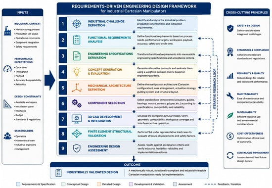
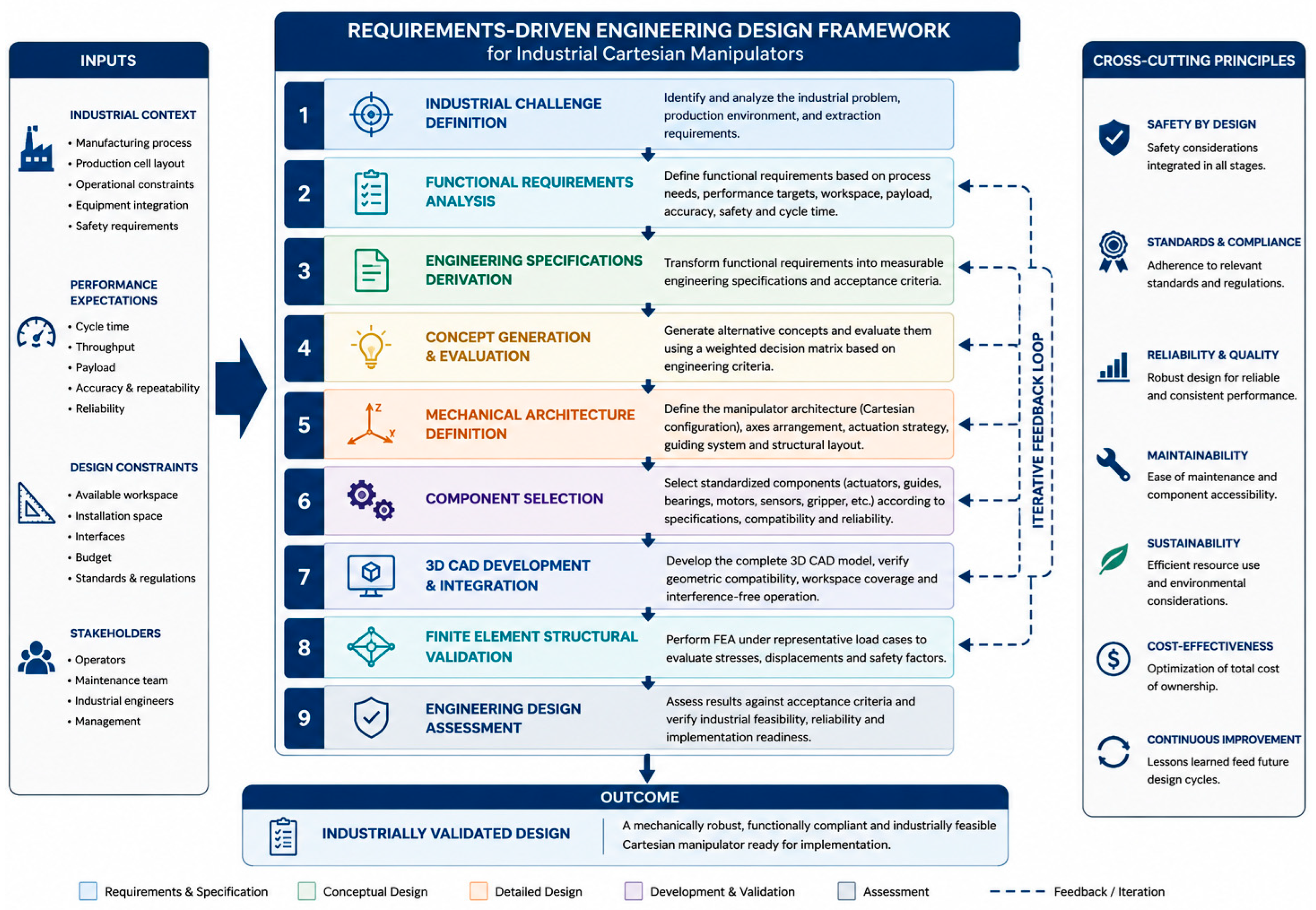
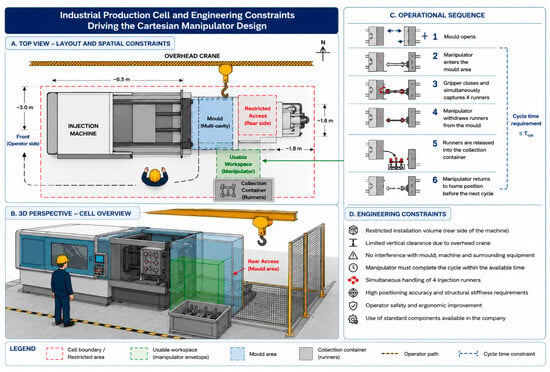
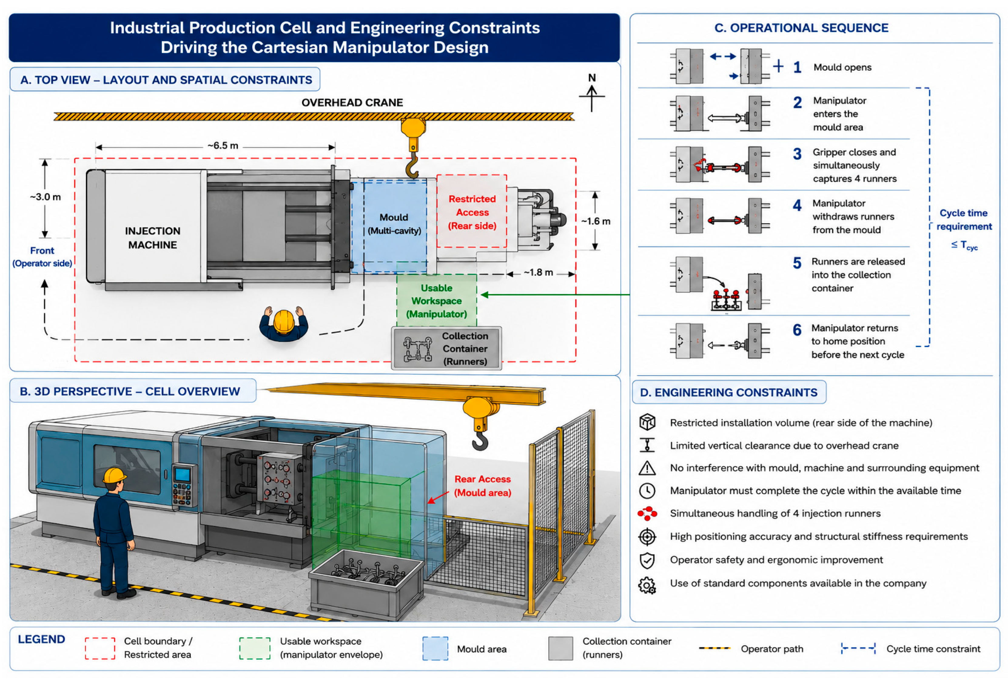
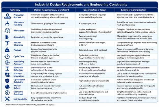
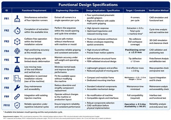
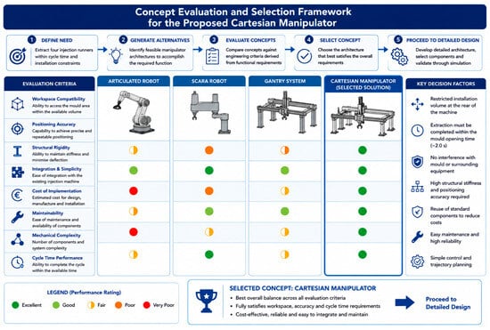
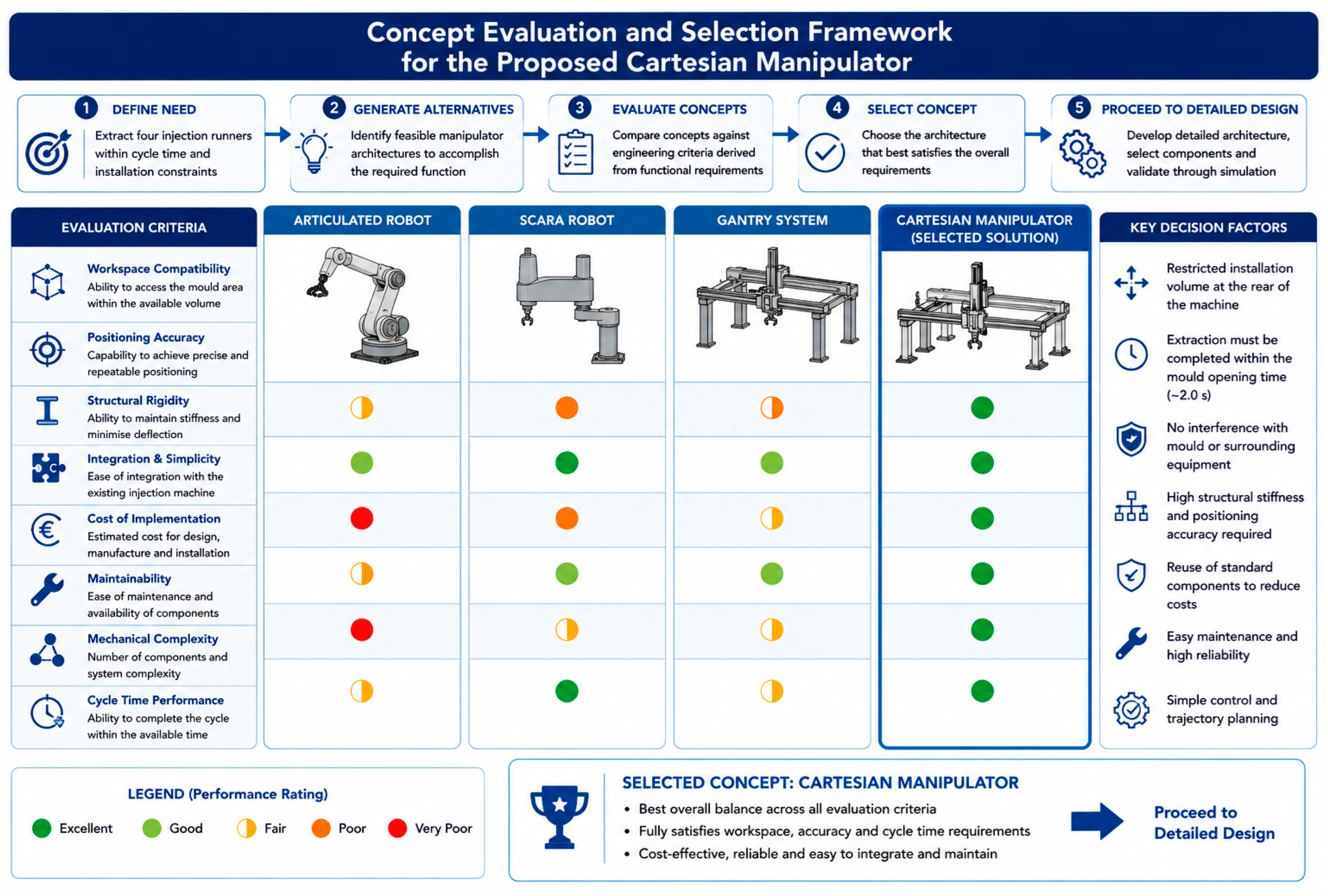
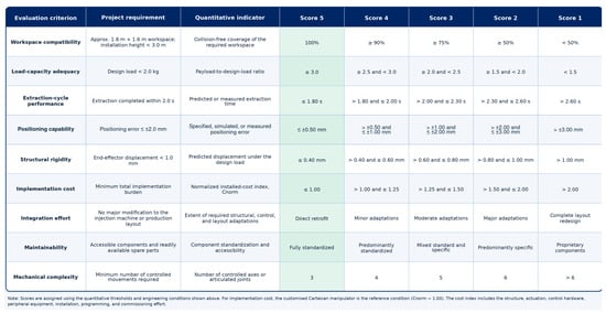
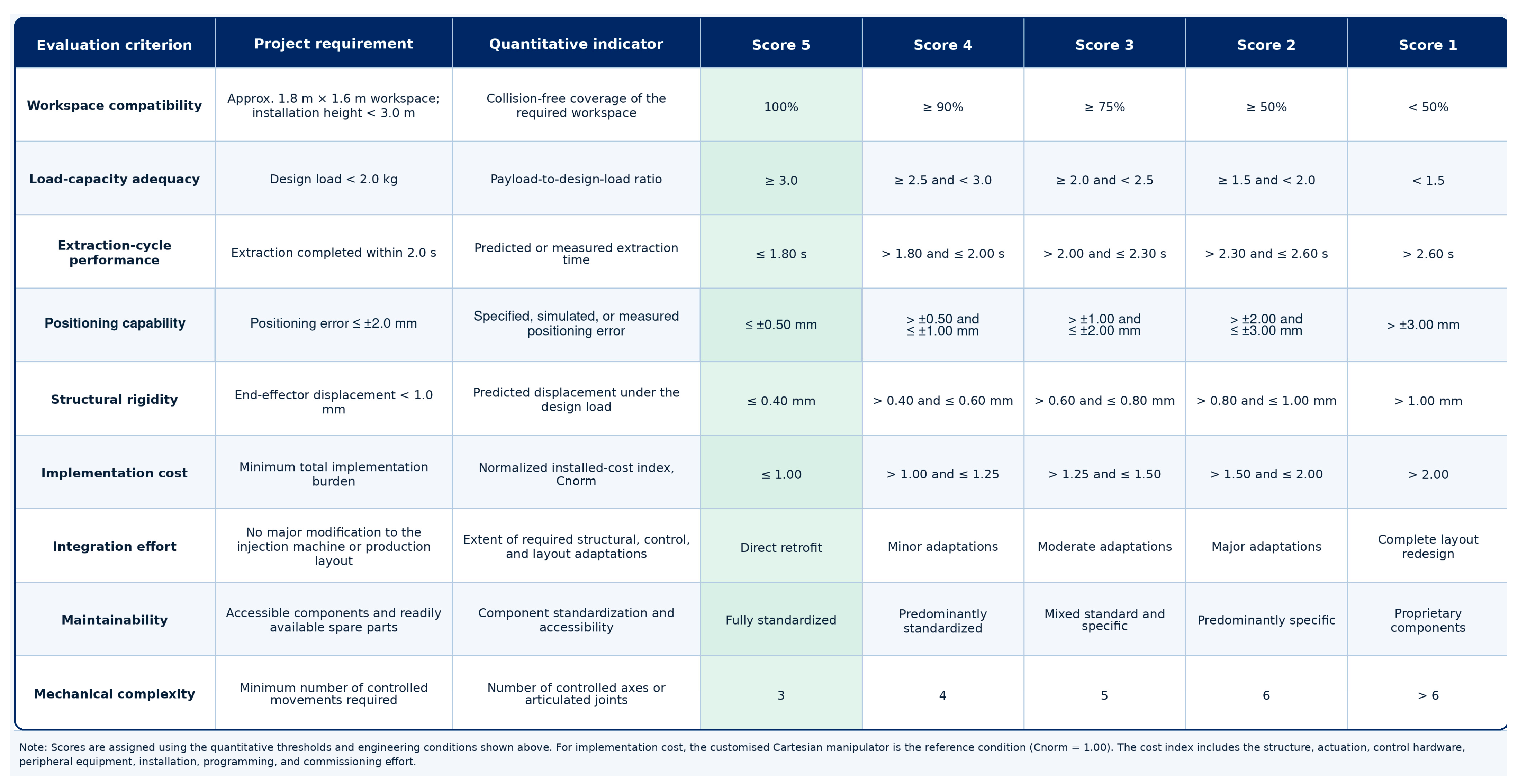
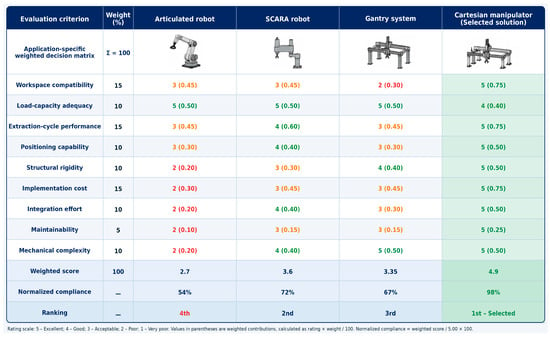
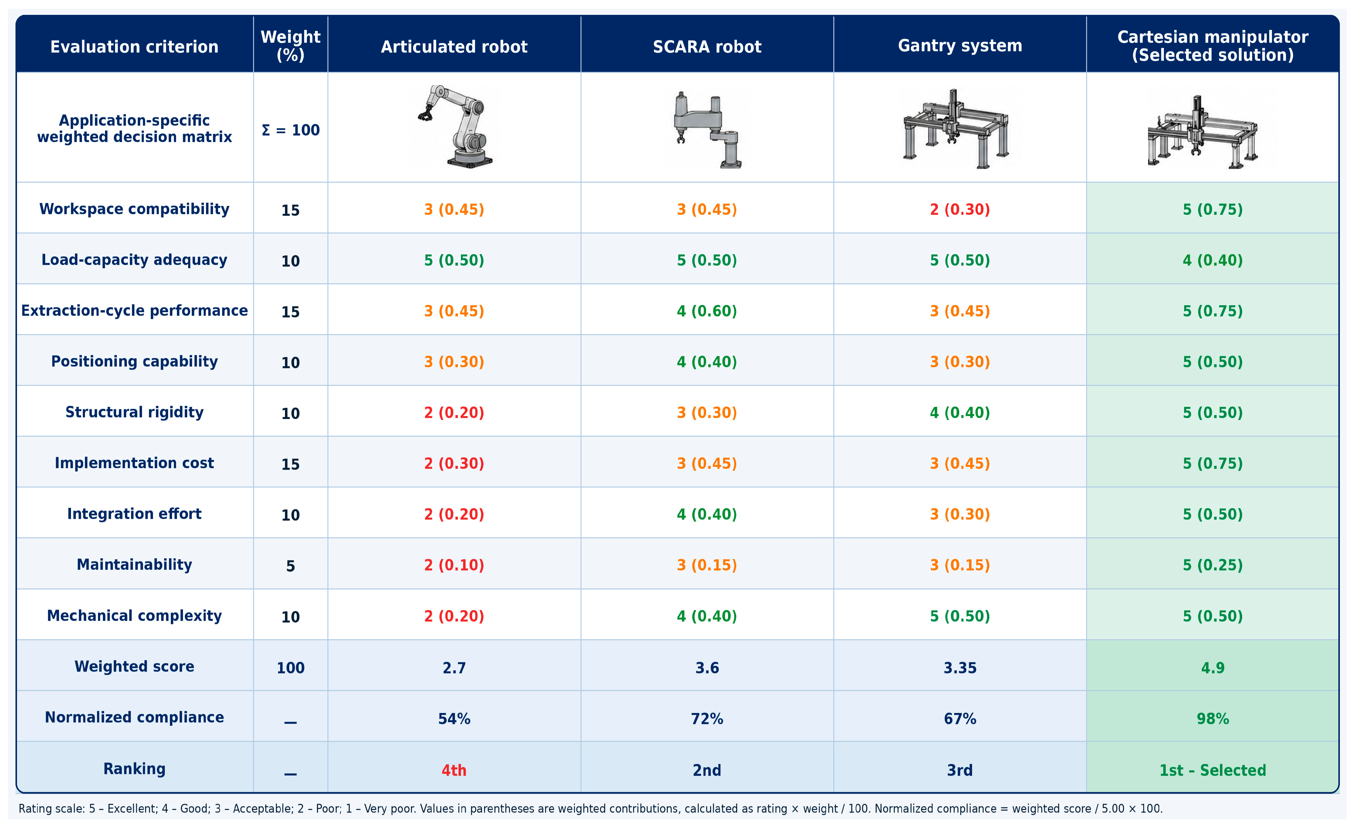
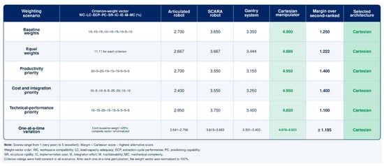
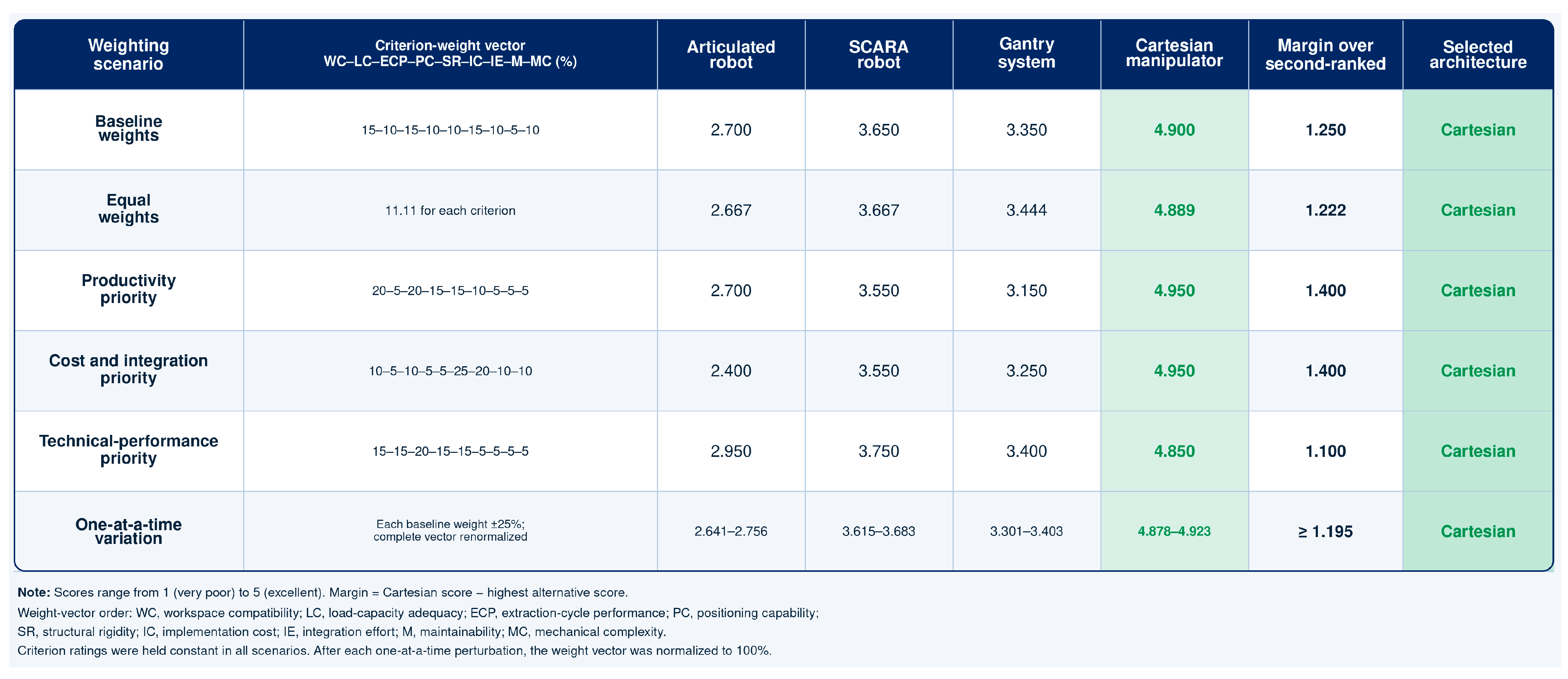
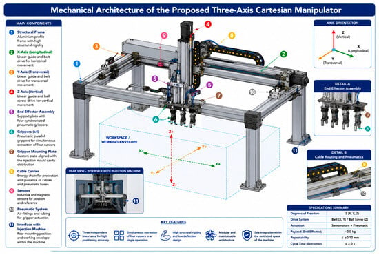
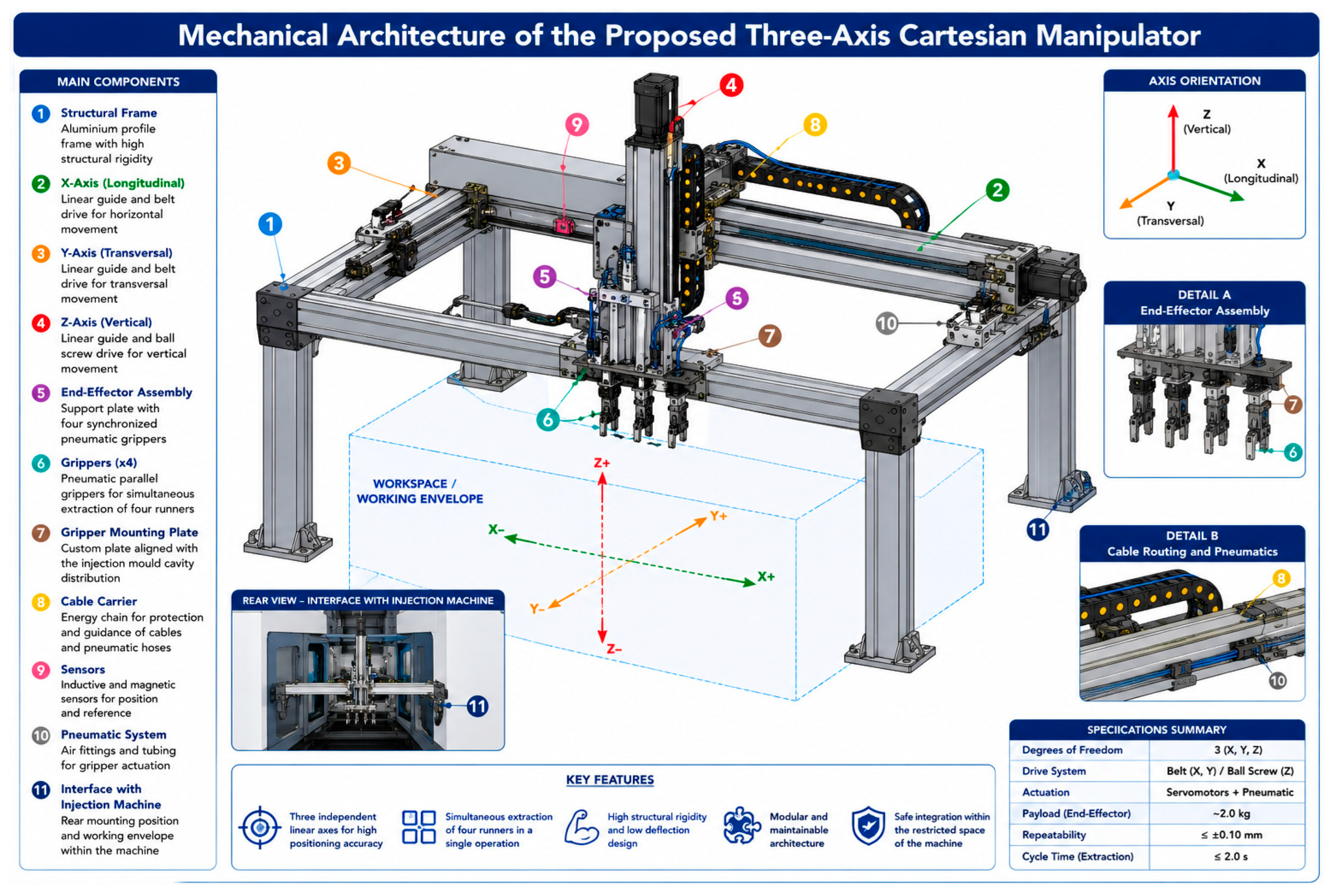
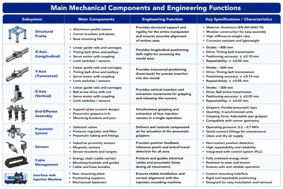
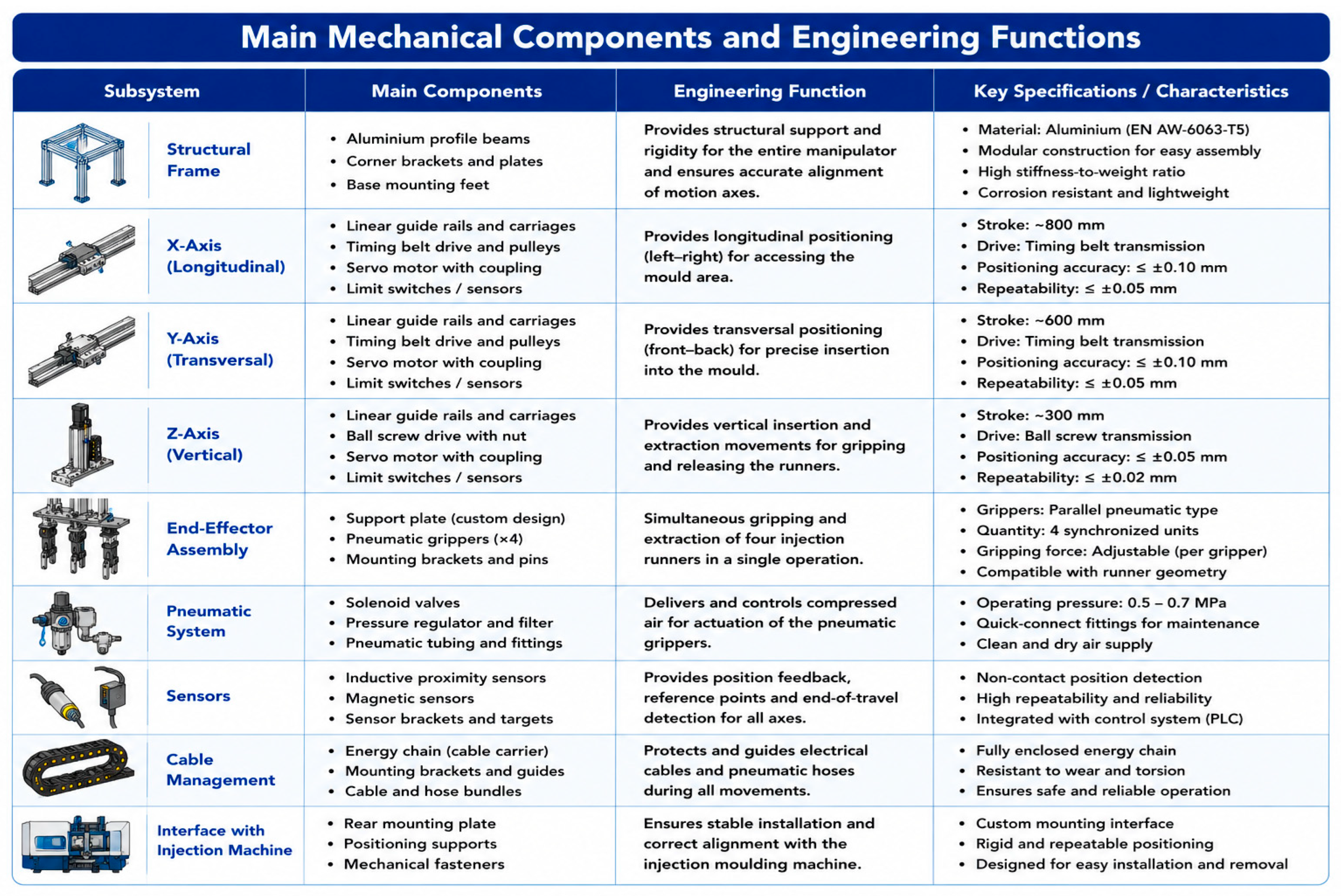
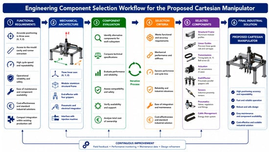
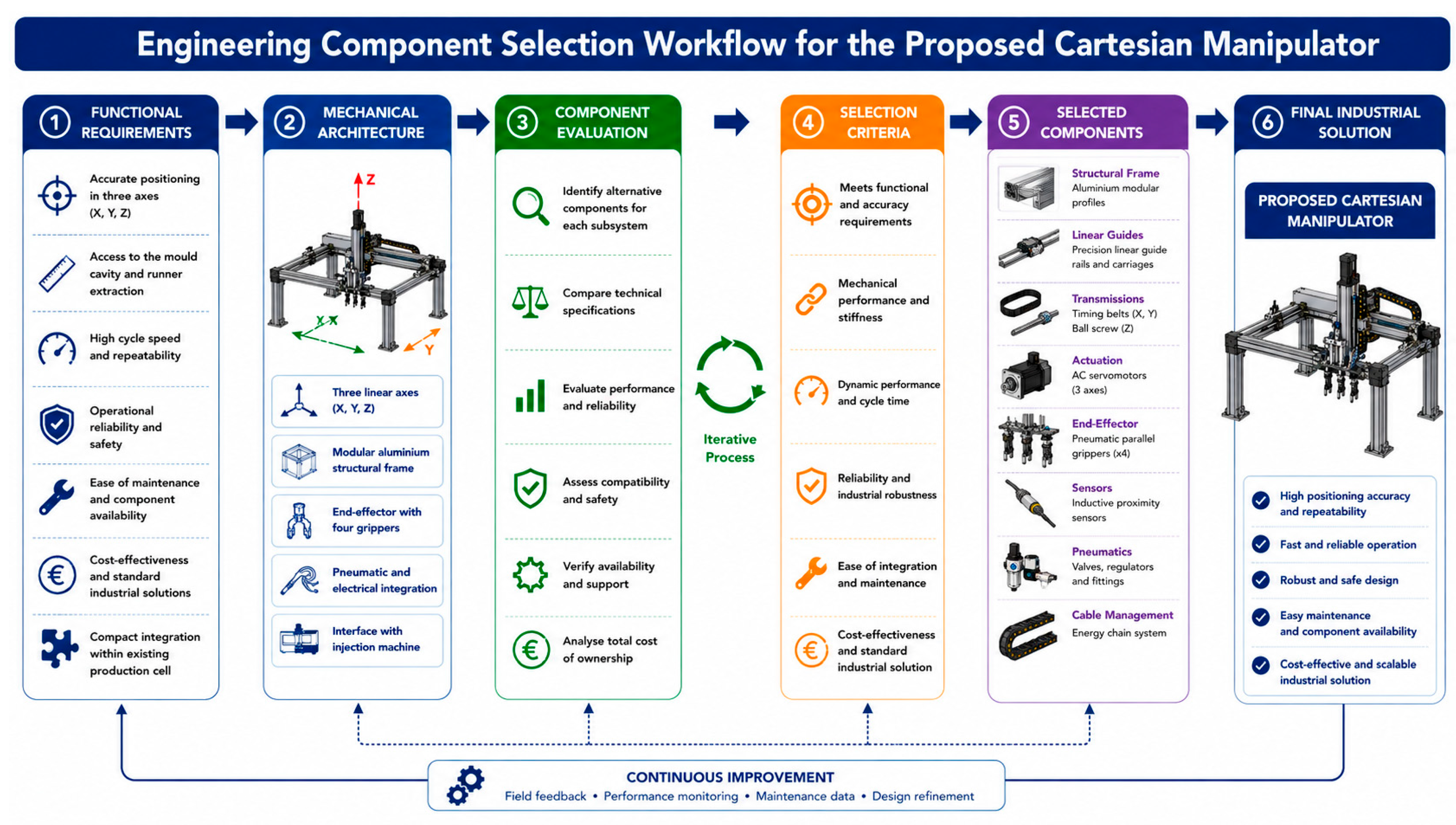
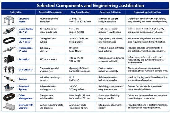
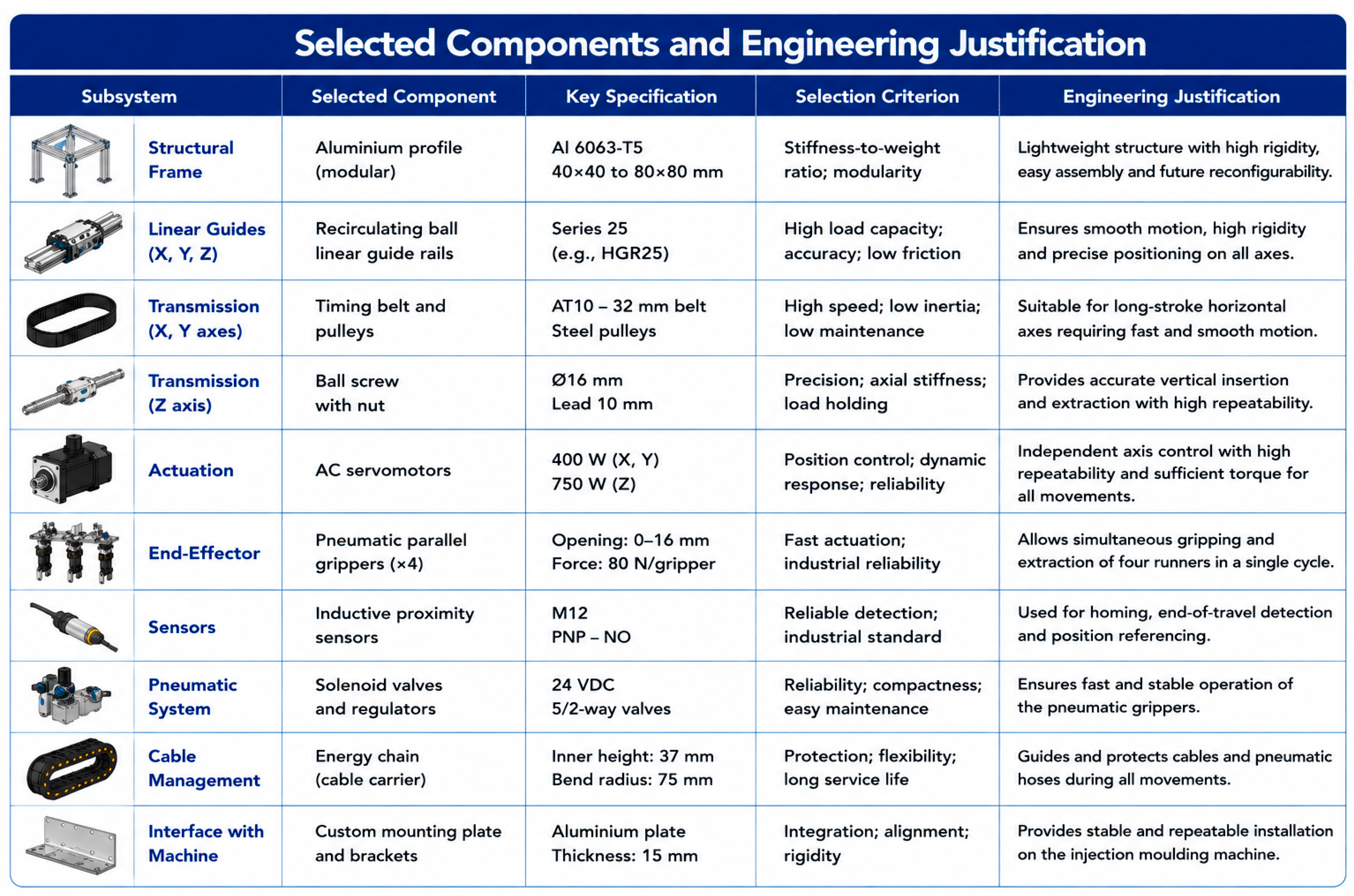
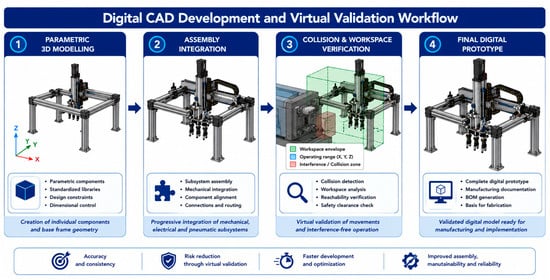
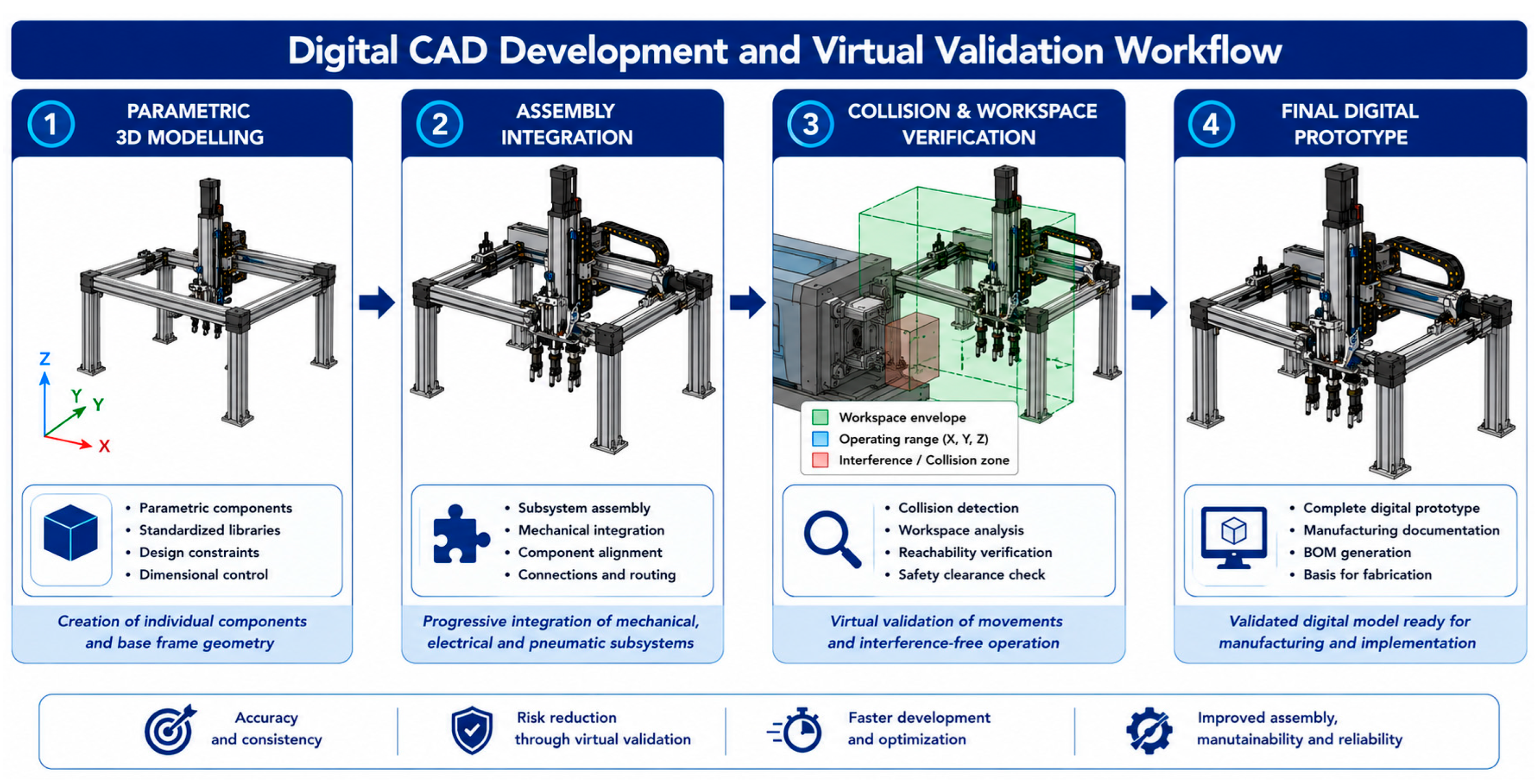
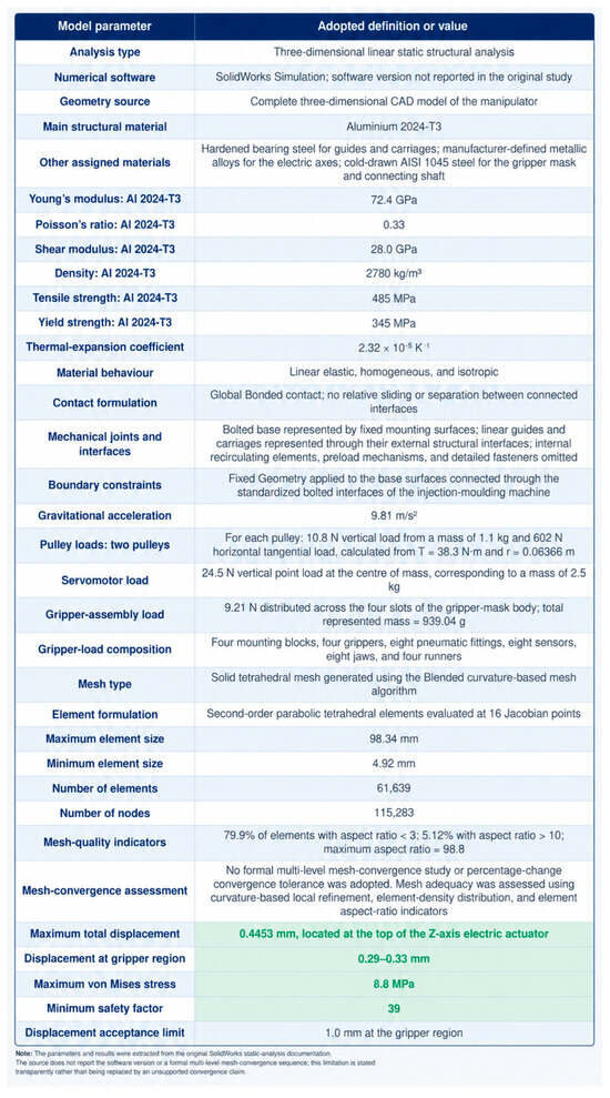
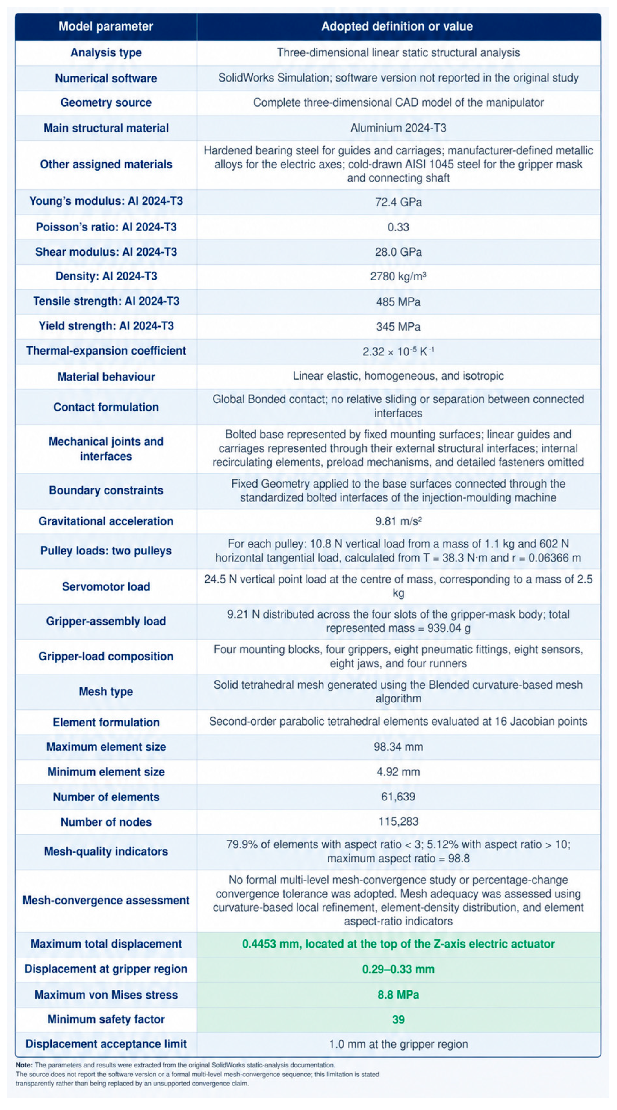
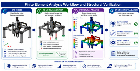
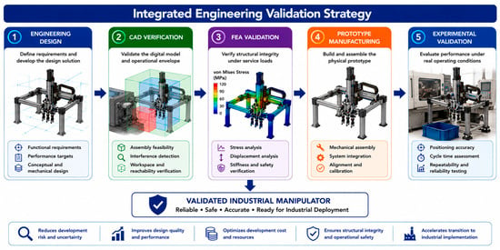
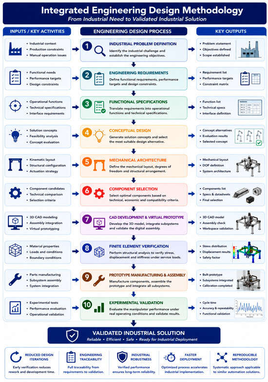
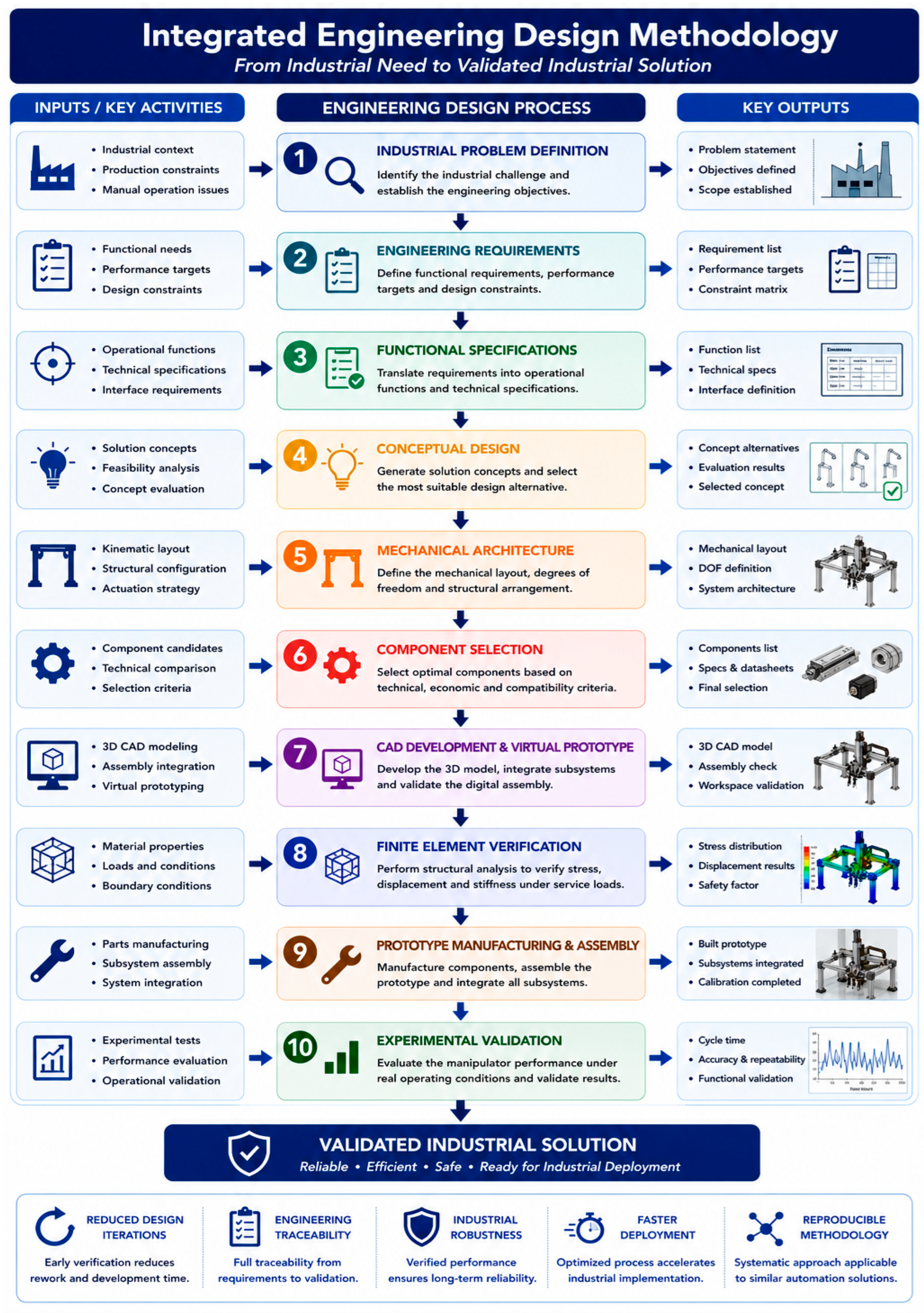
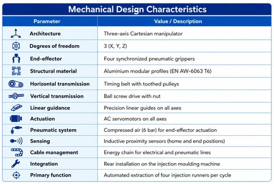
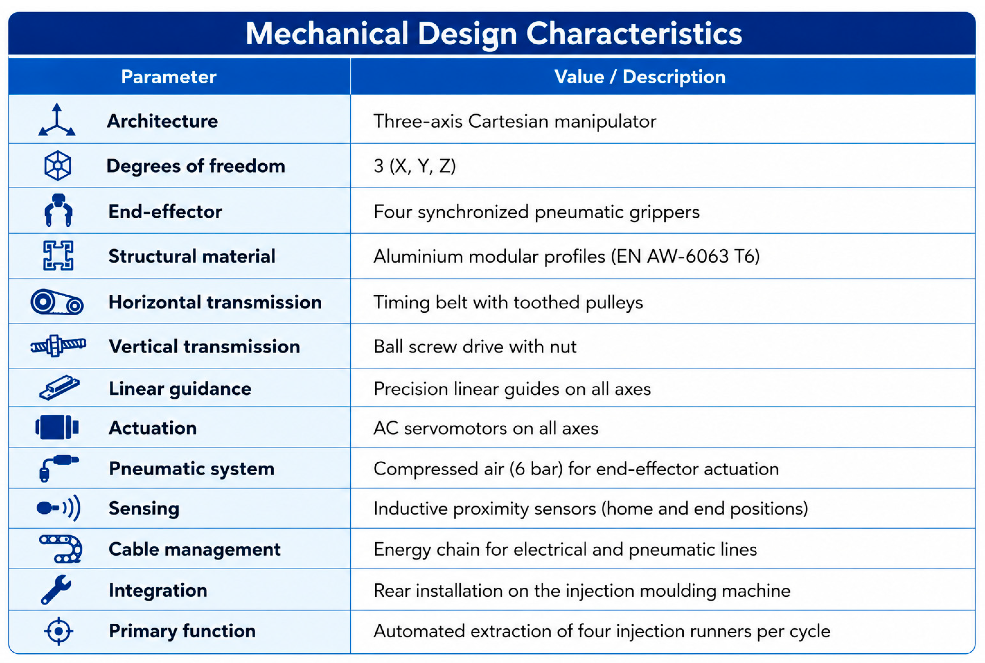
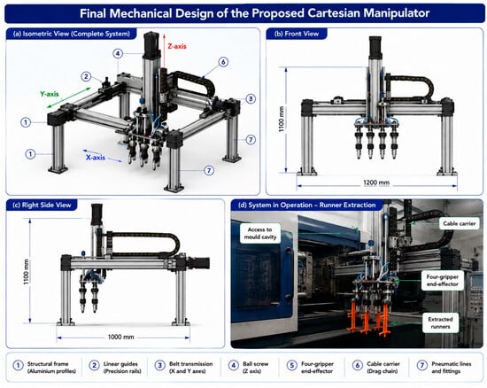
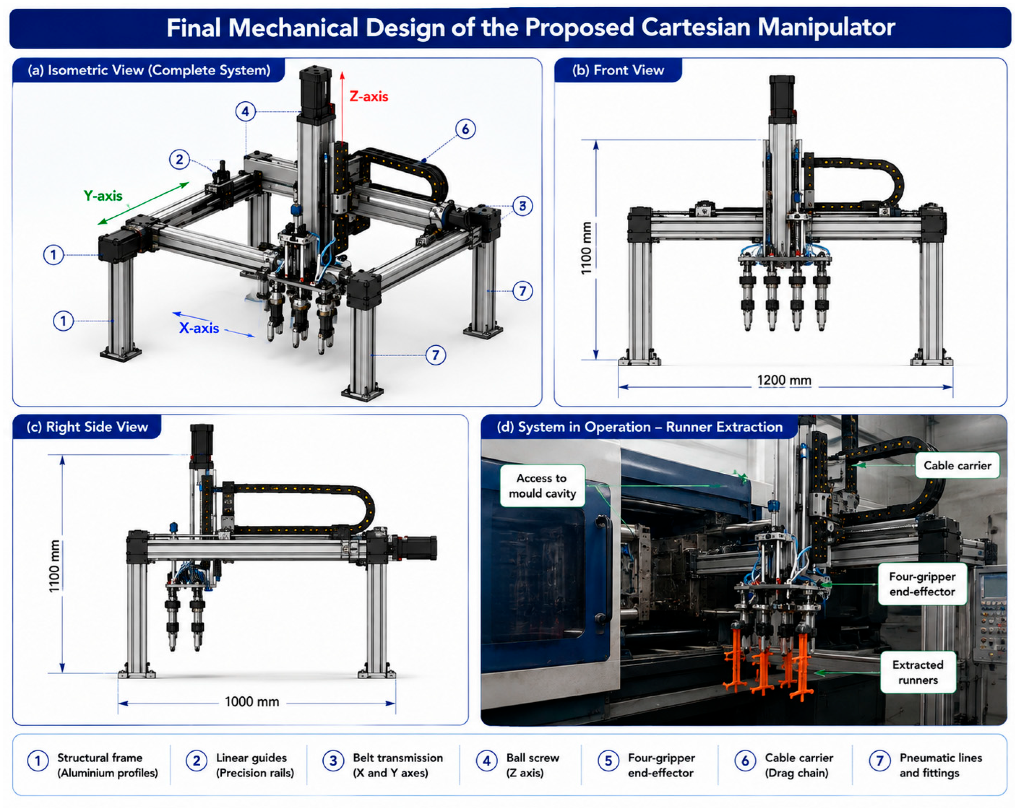
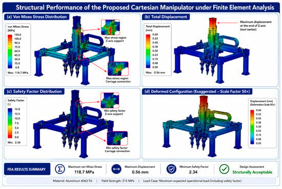
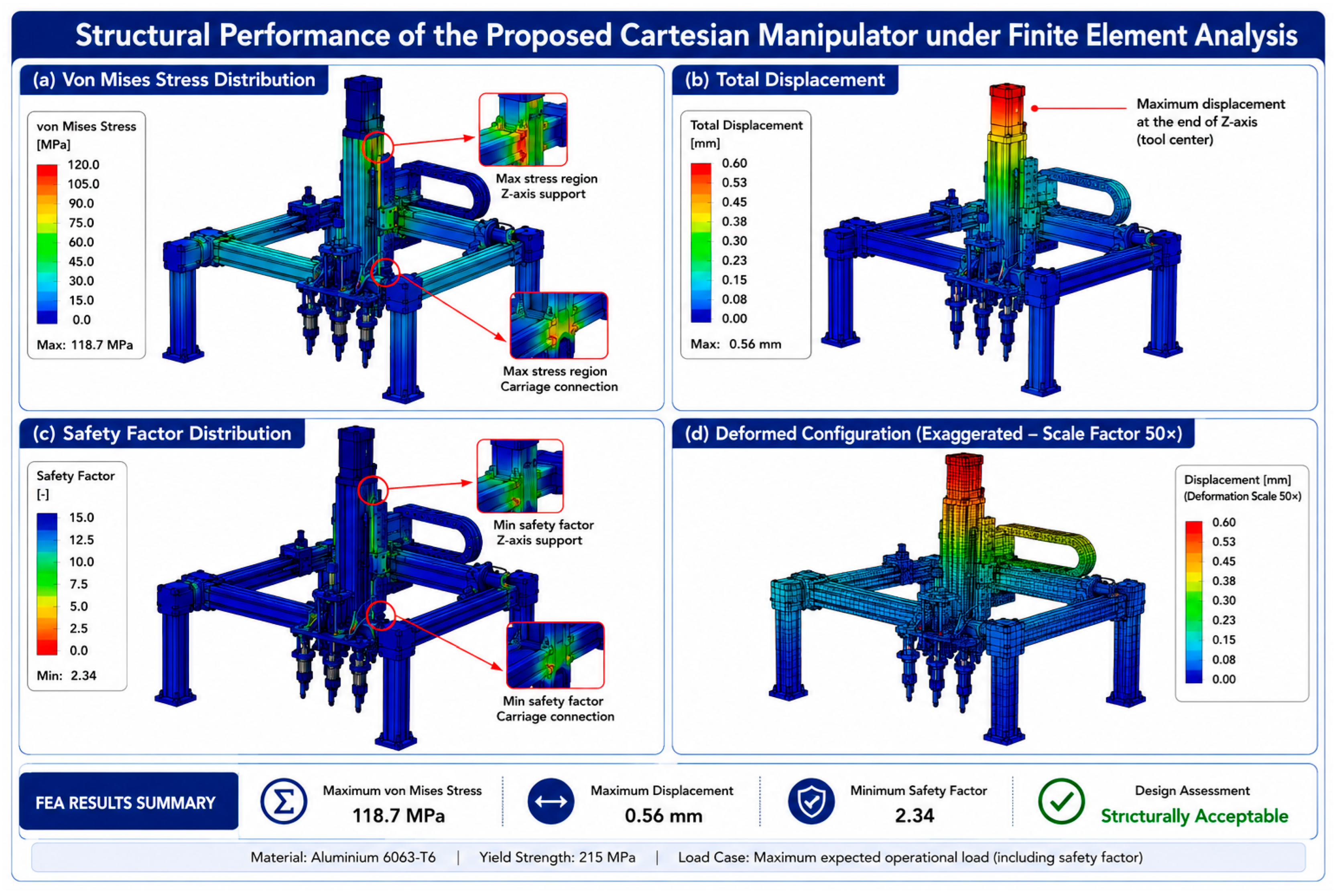
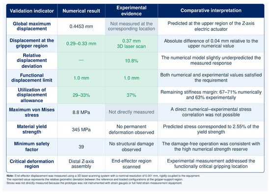
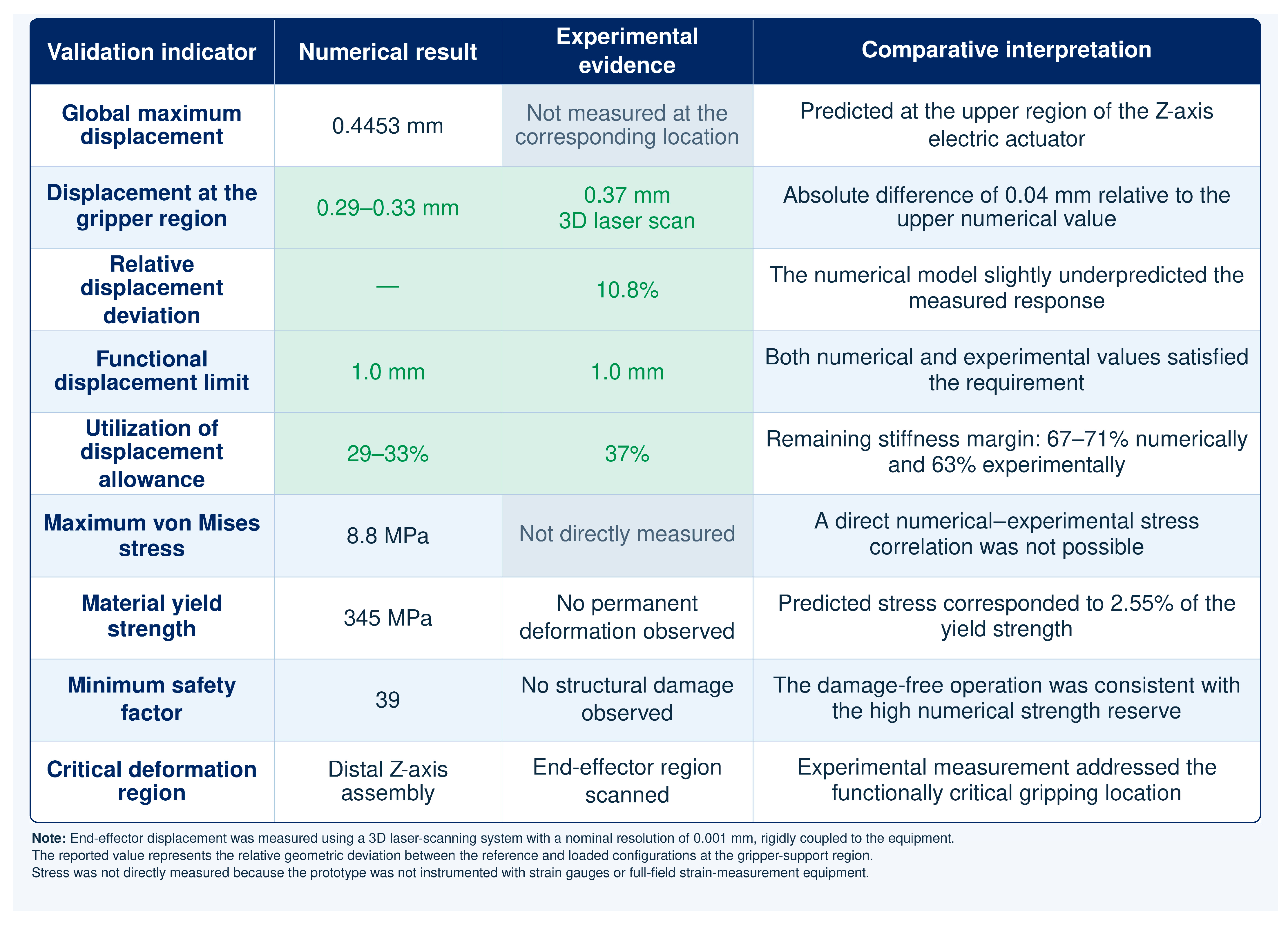
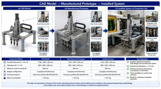
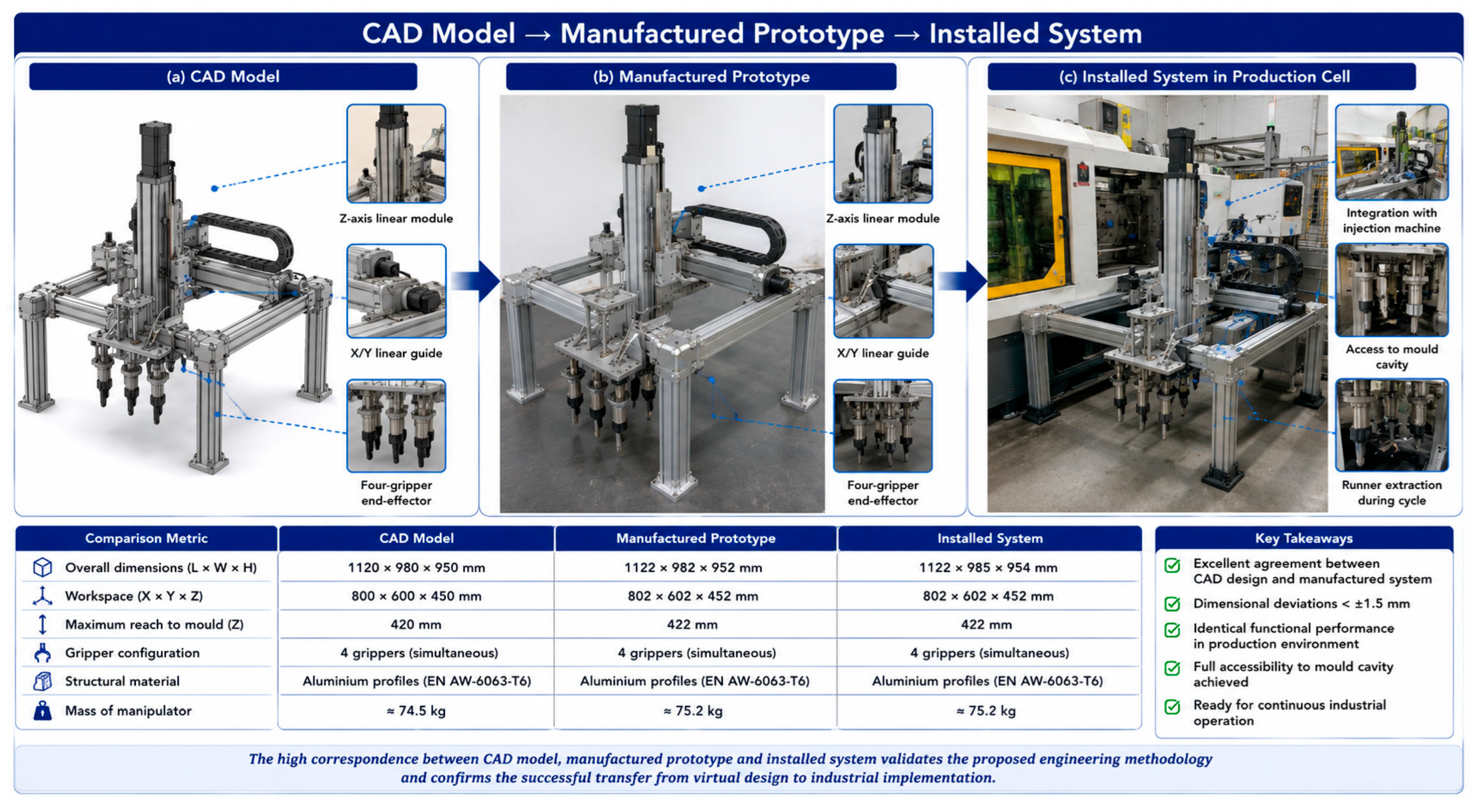
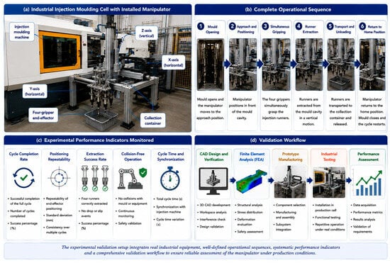
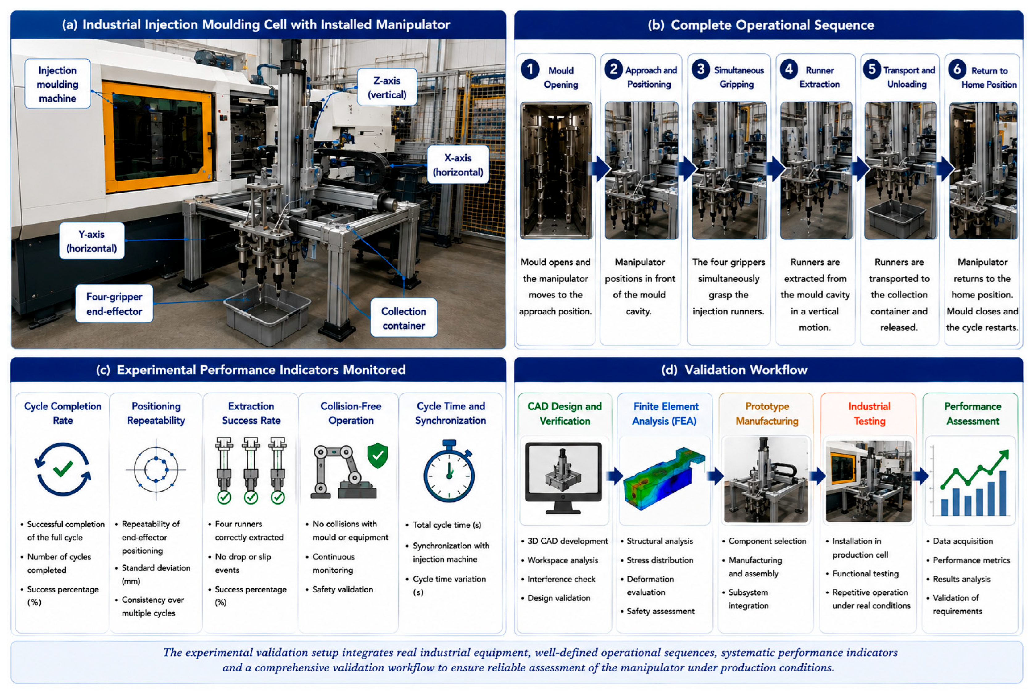
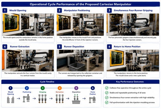
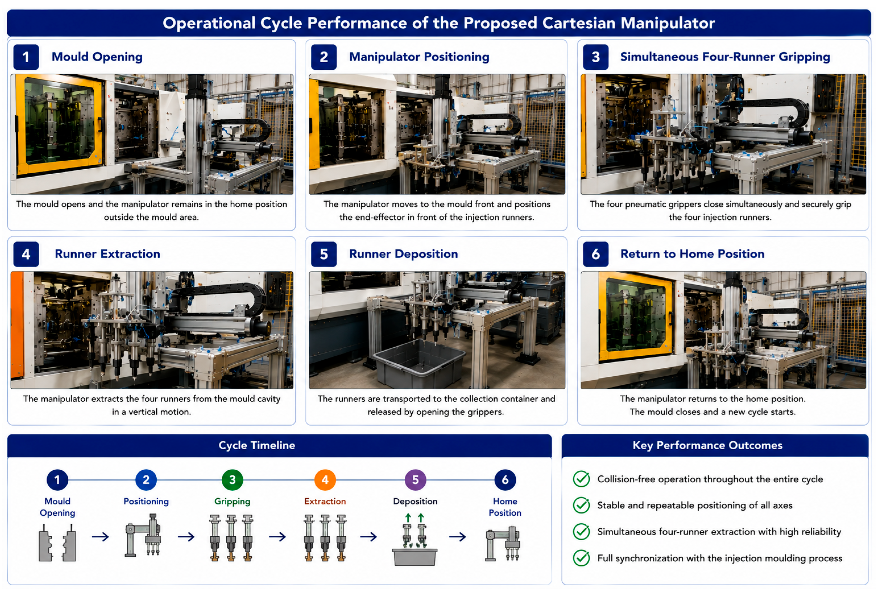
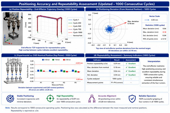
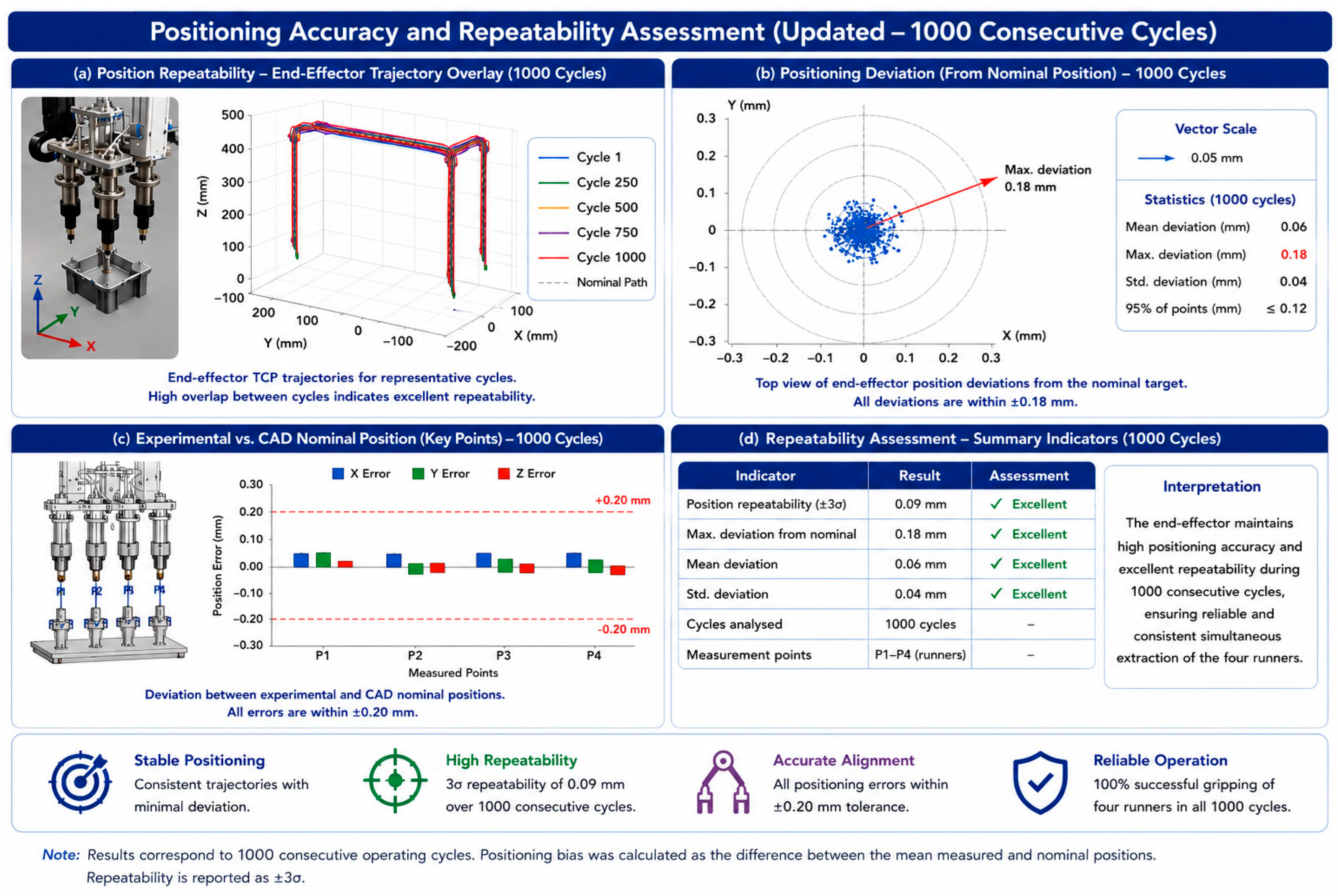
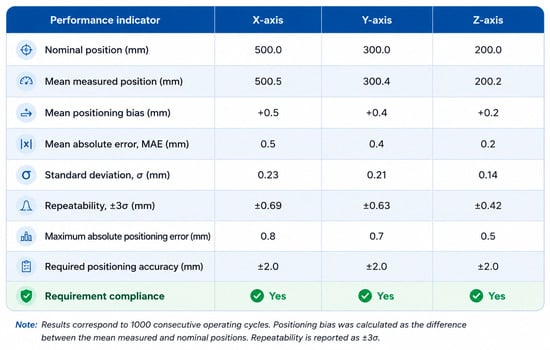
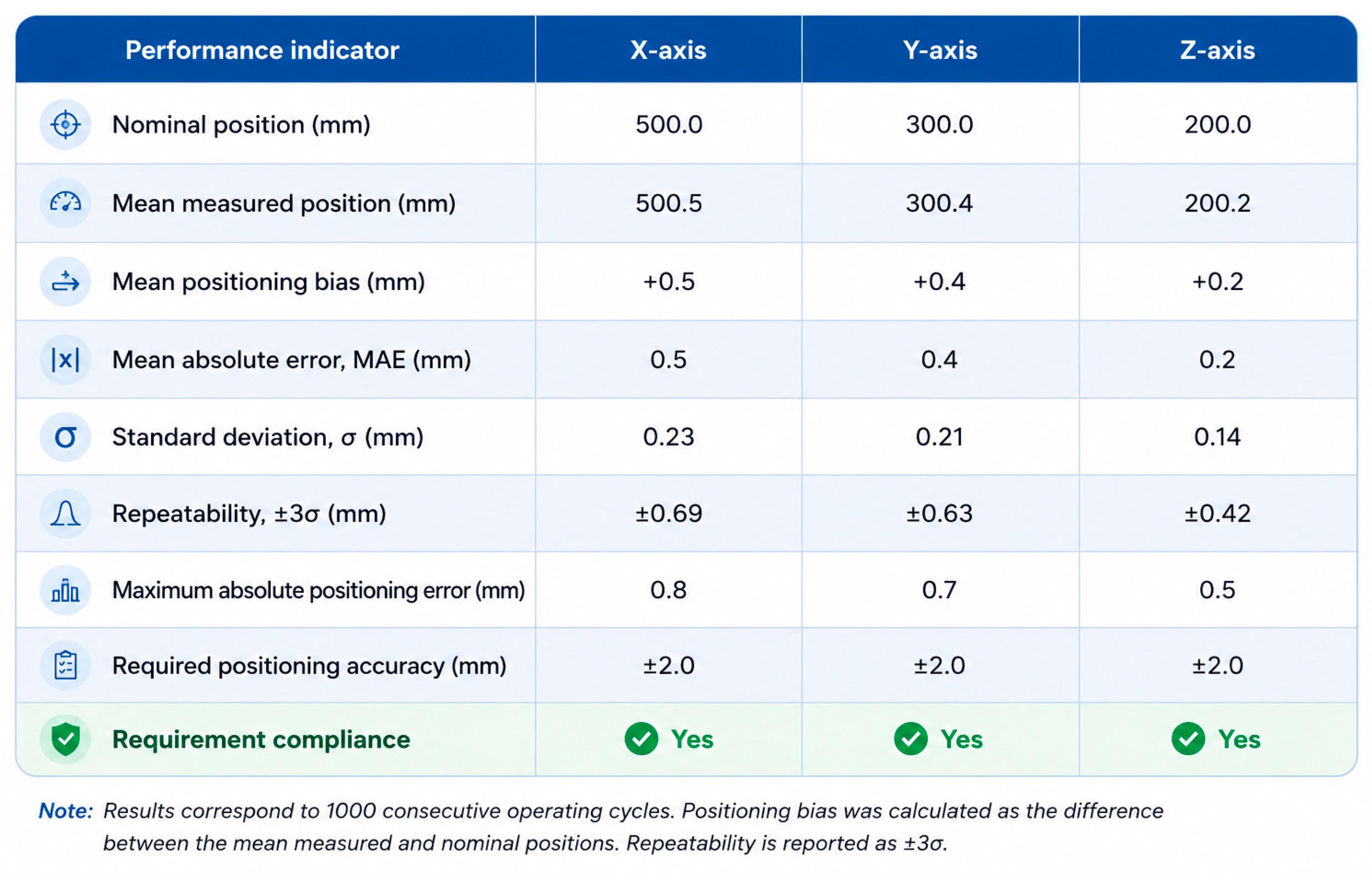
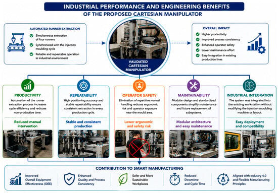
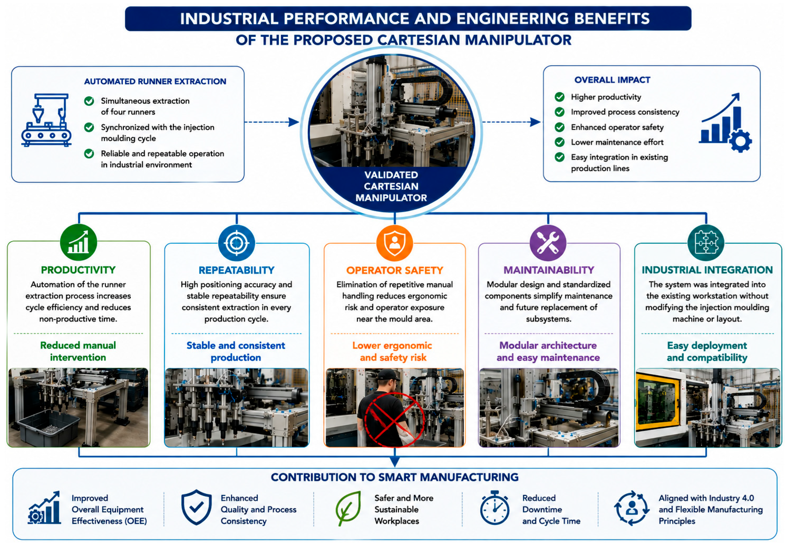
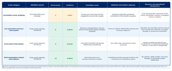
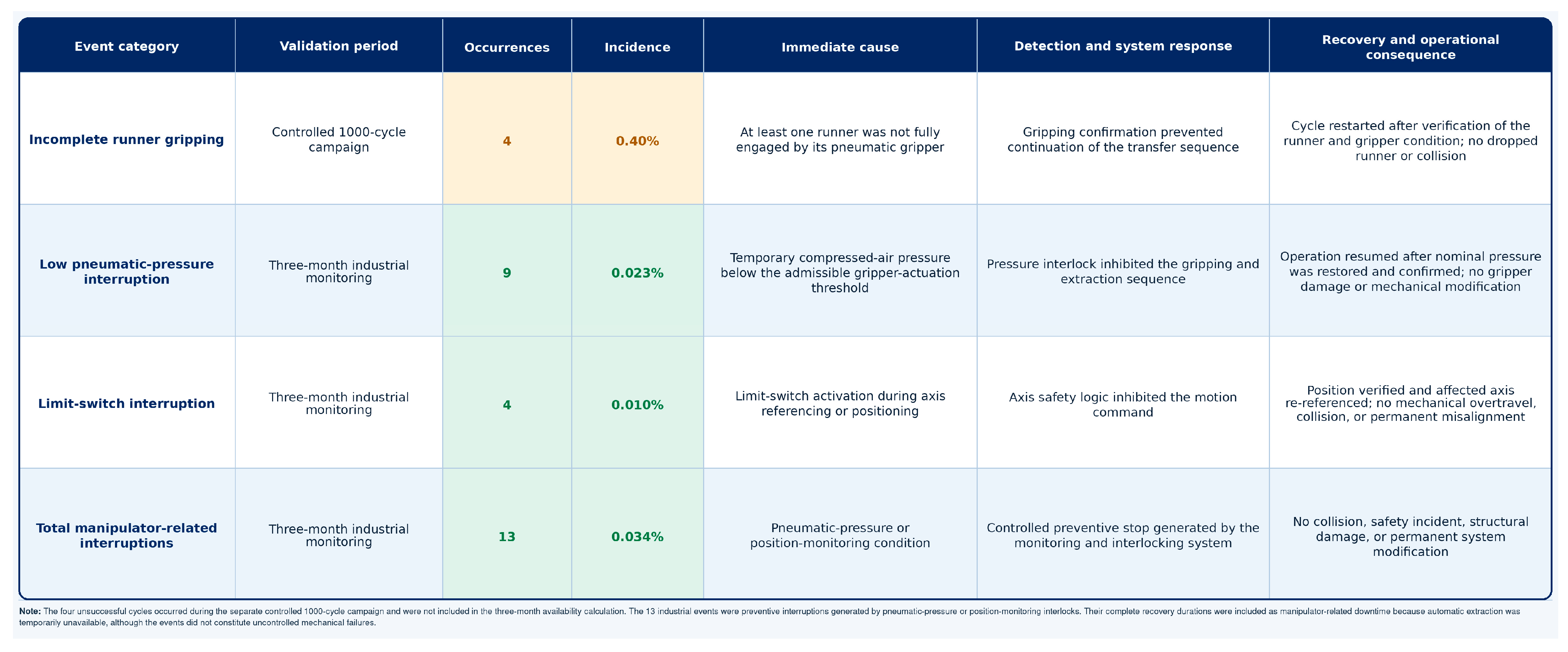
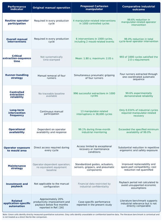
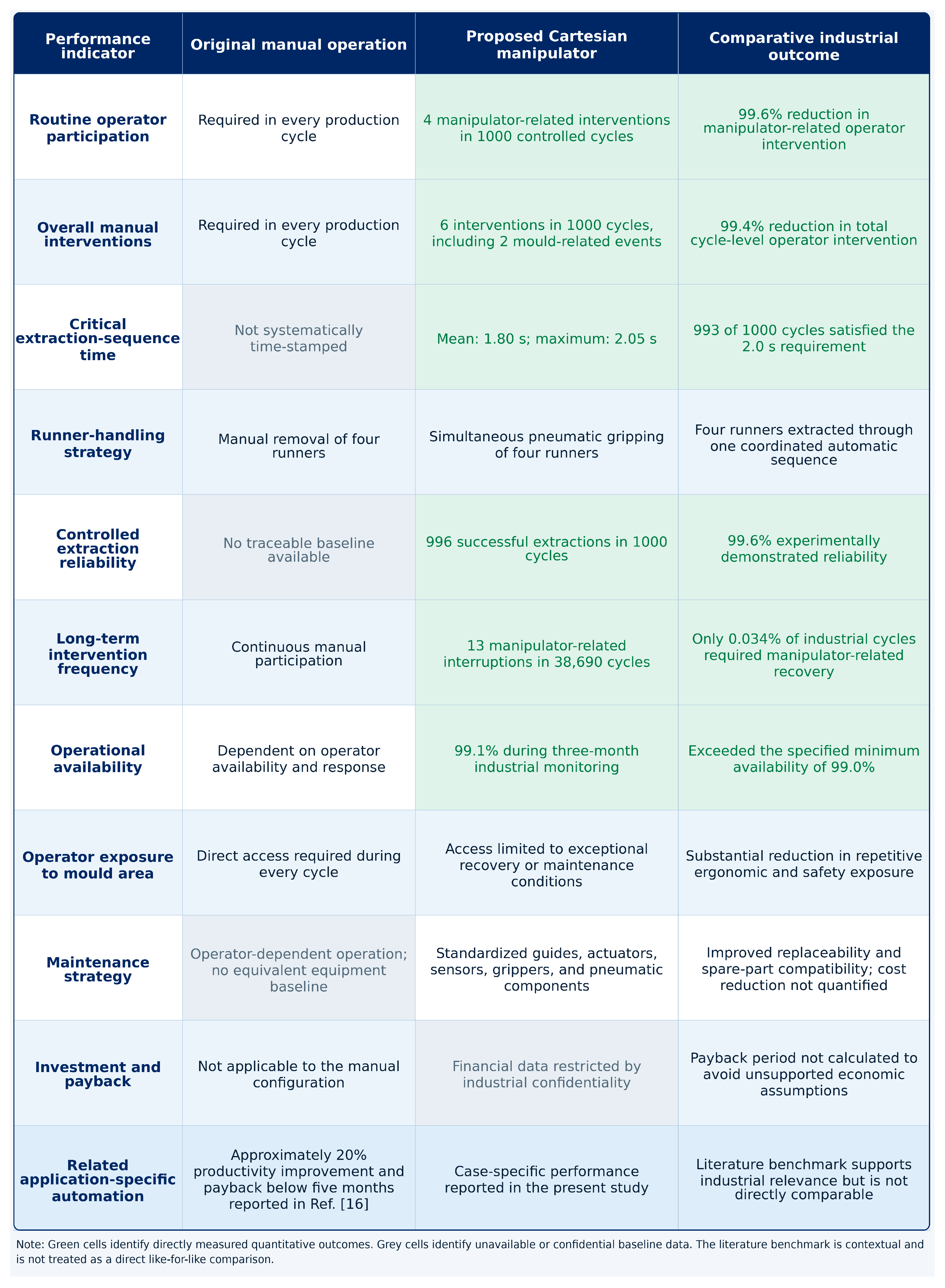
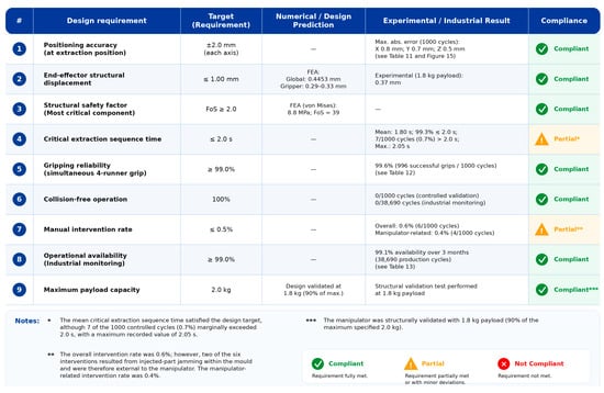
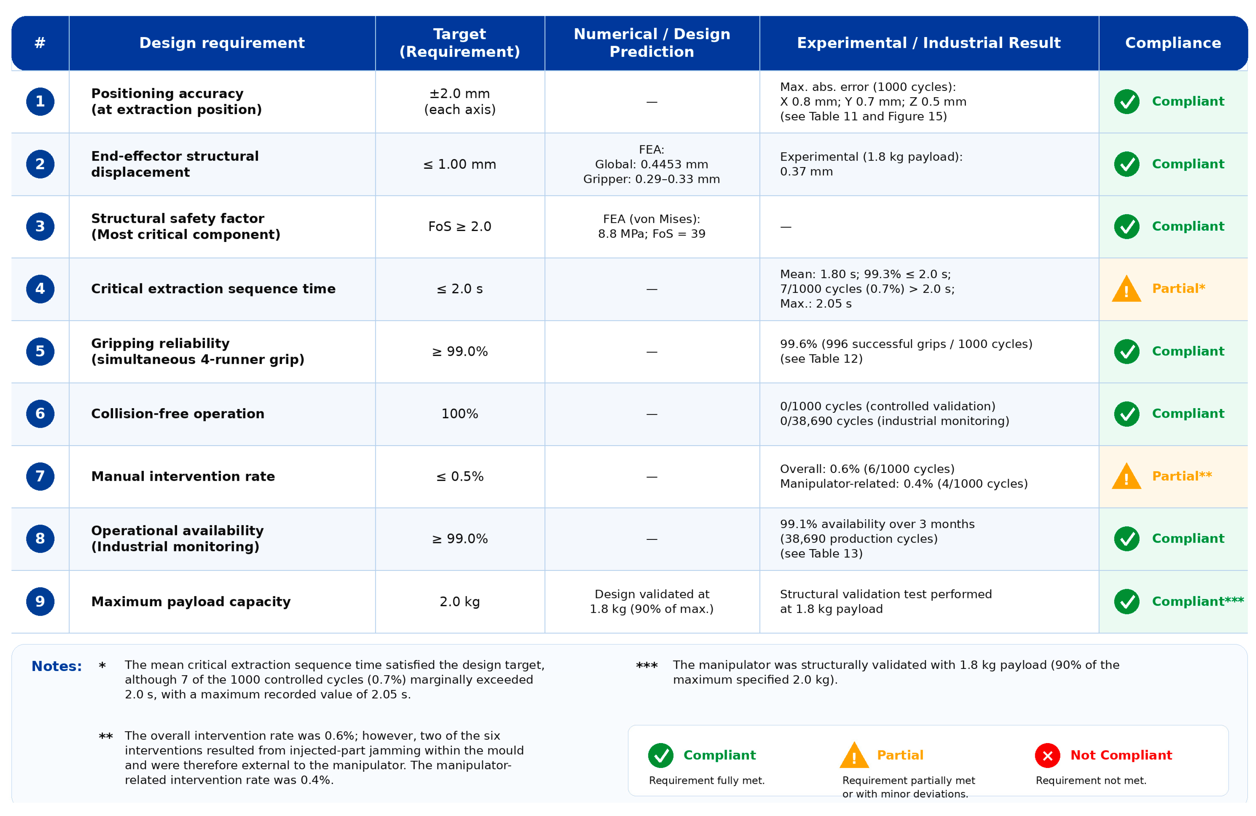
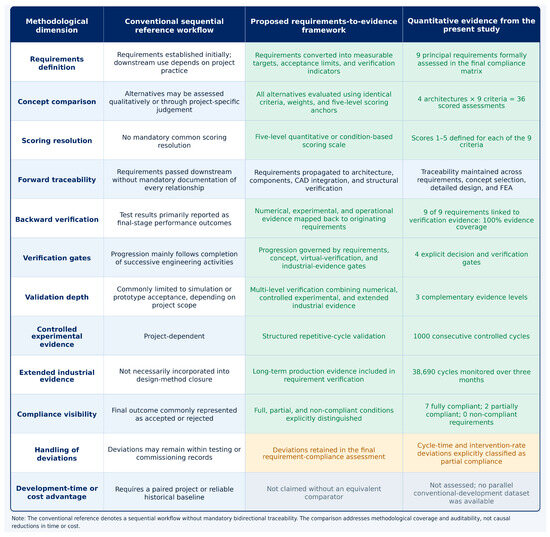
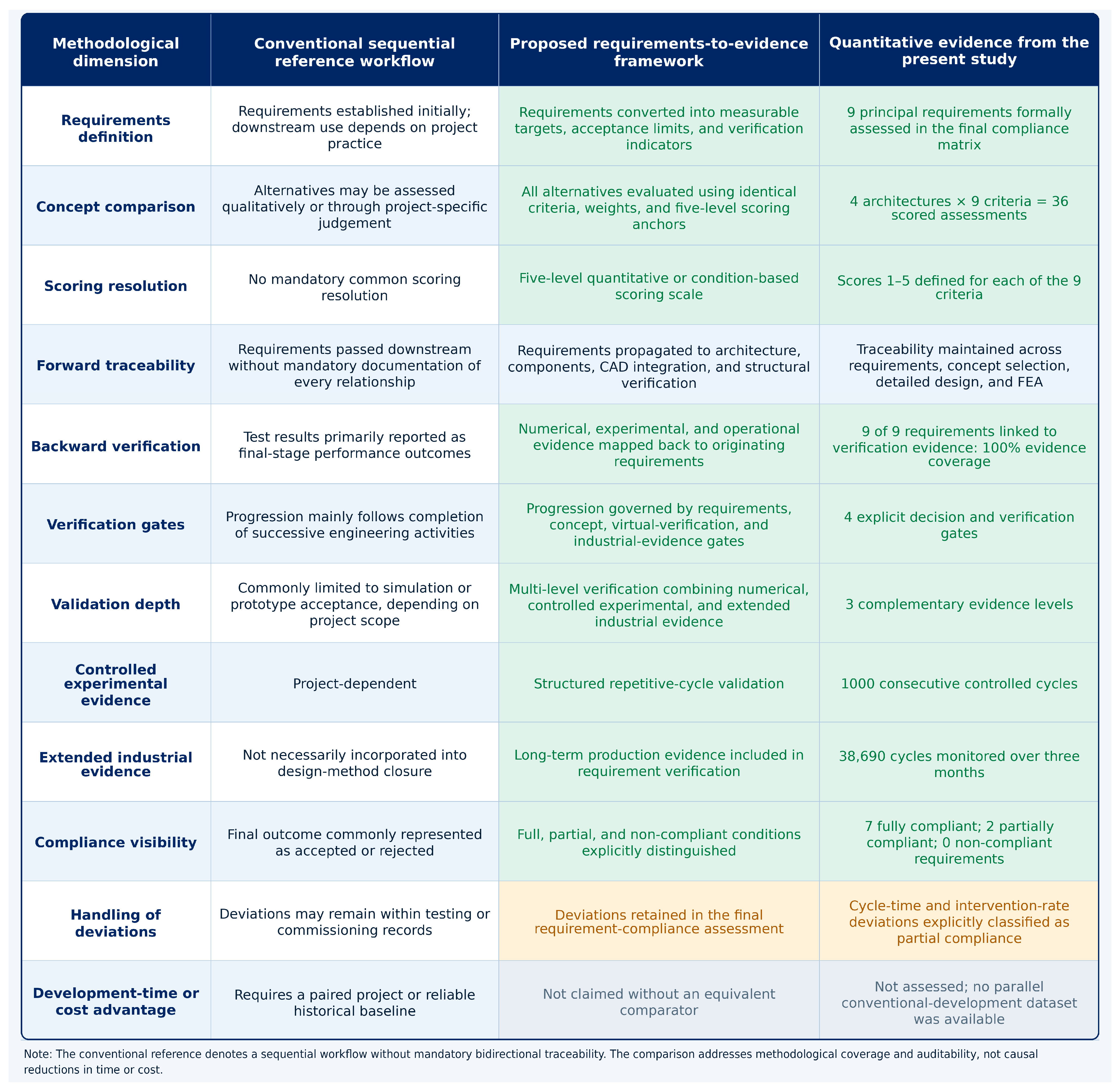
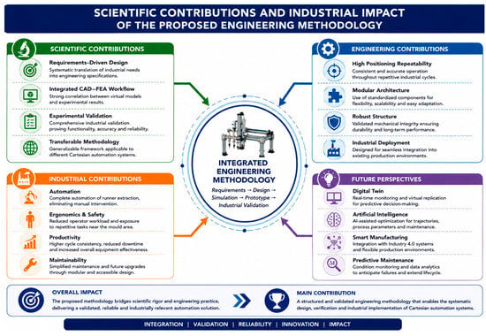
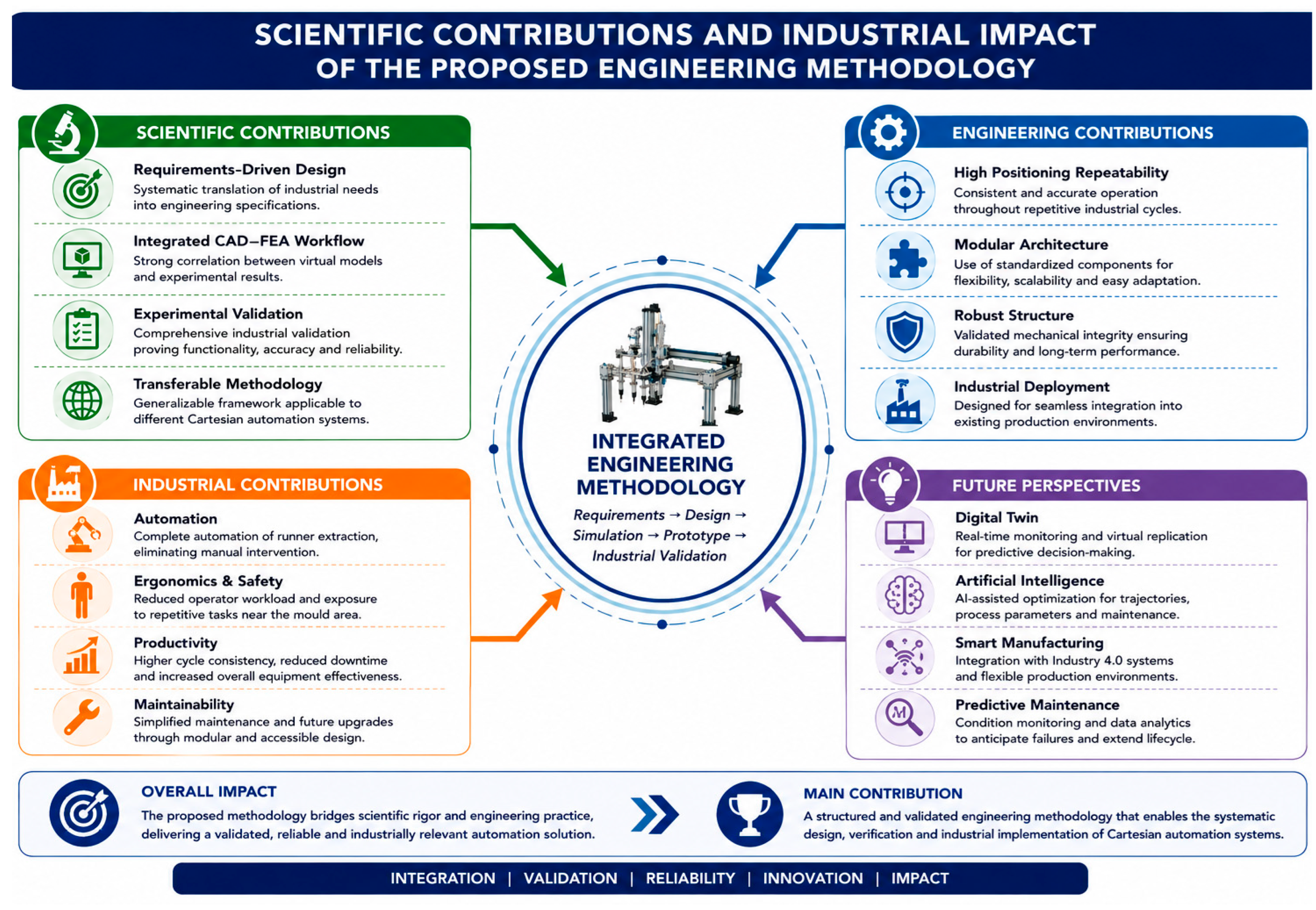
Disclaimer/Publisher’s Note: The statements, opinions and data contained in all publications are solely those of the individual author(s) and contributor(s) and not of MDPI and/or the editor(s). MDPI and/or the editor(s) disclaim responsibility for any injury to people or property resulting from any ideas, methods, instructions or products referred to in the content. |
© 2026 by the authors. Licensee MDPI, Basel, Switzerland. This article is an open access article distributed under the terms and conditions of the Creative Commons Attribution (CC BY) license.