


Abstract
Naturally occurring halloysite nanotubes (HNTs), a clay mineral characterized by a unique dual-charge architecture, offer a promising strategy for enhancing the performance of composite polymer electrolyte (CPE). In this work, HNTs are introduced as a low-cost, functional filler to simultaneously address two key limitations of poly(vinylidene fluoride-co-hexafluoropropylene) (PVDF-HFP)-based CPE: low ionic conductivity and inadequate lithium-ion transference number. The negatively charged outer surface of HNTs facilitates Li+ transport, while the positively charged inner lumen confines anions such as TFSI−. Controlled acid etching (6 M HCl, 12 h) further optimizes this structure by removing surface impurities and enlarging the lumen, thereby enhancing both charge-directed ion transport pathways. The resulting HNT-modified CPE achieves a high ionic conductivity of 6.1 × 10⁻⁴ S⋅cm−1 and a Li+ transference number of 0.73. When assembled into Li||CPE||LiFePO4 cells, the electrolyte enables stable cycling over 300 cycles at 0.2C, retains 119.2 mAh/g at 2C, and delivers 85.7 mAh/g even at 5C, demonstrating excellent cycling stability and rate capability. This study reveals the potential of mineral-derived nanomaterials, with their inherent structural and physicochemical properties, to serve as key functional components in high-performance batteries.
1. Introduction
The development of advanced functional materials from naturally abundant clay minerals represents a meaningful pathway toward sustainable technology. Among these, kaolin-group minerals are especially noteworthy due to their global availability, tunable structure, and versatile applications [1,2]. Of particular interest are halloysite nanotubes (HNTs), which naturally occur in a unique nanotubular morphology and exhibit distinct structural and physicochemical properties that make them a compelling subject for both fundamental research and functional applications. HNTs are naturally occurring 1:1 clay minerals formed through the rolling of kaolinite layers, with a chemical composition of Al2Si2O5(OH)4·nH2O [3,4]. They typically exhibit a hollow tubular structure with a high aspect ratio, measuring 500–1000 nm in length and 15–70 nm in diameter [5]. The nanotube wall features a distinct bilayer architecture: the outer surface consists mainly of siloxane groups (Si–O–Si), whereas the inner lumen is lined with aluminol groups (Al–OH) [6,7]. The applications of HNTs extend far beyond conventional ceramics. They are now widely employed in polymer composites, paper manufacturing, surface coatings, and catalytic systems, and further penetrate emerging fields such as environmental remediation, advanced functional materials, biomedicine, fine chemicals, energy storage devices, and chemical processing, reflecting a broad and promising trajectory [8,9,10,11,12,13,14,15,16].
Notably, the physicochemical properties of HNTs are largely governed by their unique structure. The structural asymmetry of HNTs gives rise to a unique charge distribution in aqueous environments, featuring a negatively charged outer surface and a positively charged inner lumen. This negative-outside/positive-inside dual-charge characteristic, combined with their nanoconfinement effect, renders HNTs highly efficient nanoscale ion regulators [17,18,19,20,21]. These properties underscore the significant potential of HNTs in the field of solid-state electrolytes, which represent the forthcoming technological frontier for lithium-ion batteries. Currently, solid-state electrolytes are mainly categorized into three types: inorganic solid-state electrolyte (SSE), polymer solid-state electrolyte (PSE), and composite polymer electrolytes (CPE) [22,23,24,25,26,27,28,29,30,31,32]. Among these three major systems, CPE have emerged as one of the most practically viable options [33,34,35,36]. By incorporating inorganic fillers, CPE can partially overcome their inherently low room-temperature ionic conductivity, while preserving the intrinsic flexibility of polymers and enabling intimate, stable interfacial contact with electrodes. However, in most reported CPE, a significant fraction of ion transport remains dominated by anion migration, leading to a low lithium transference number and marked concentration polarization under high-current operation. Additionally, many conventional inorganic fillers rely on intricate synthesis procedures or expensive precursors, which hampers their scalability and practical deployment. In contrast, HNTs offer a promising alternative due to their distinctive structural and surface-charge properties, which can effectively address these persistent challenges [37].
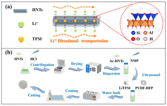
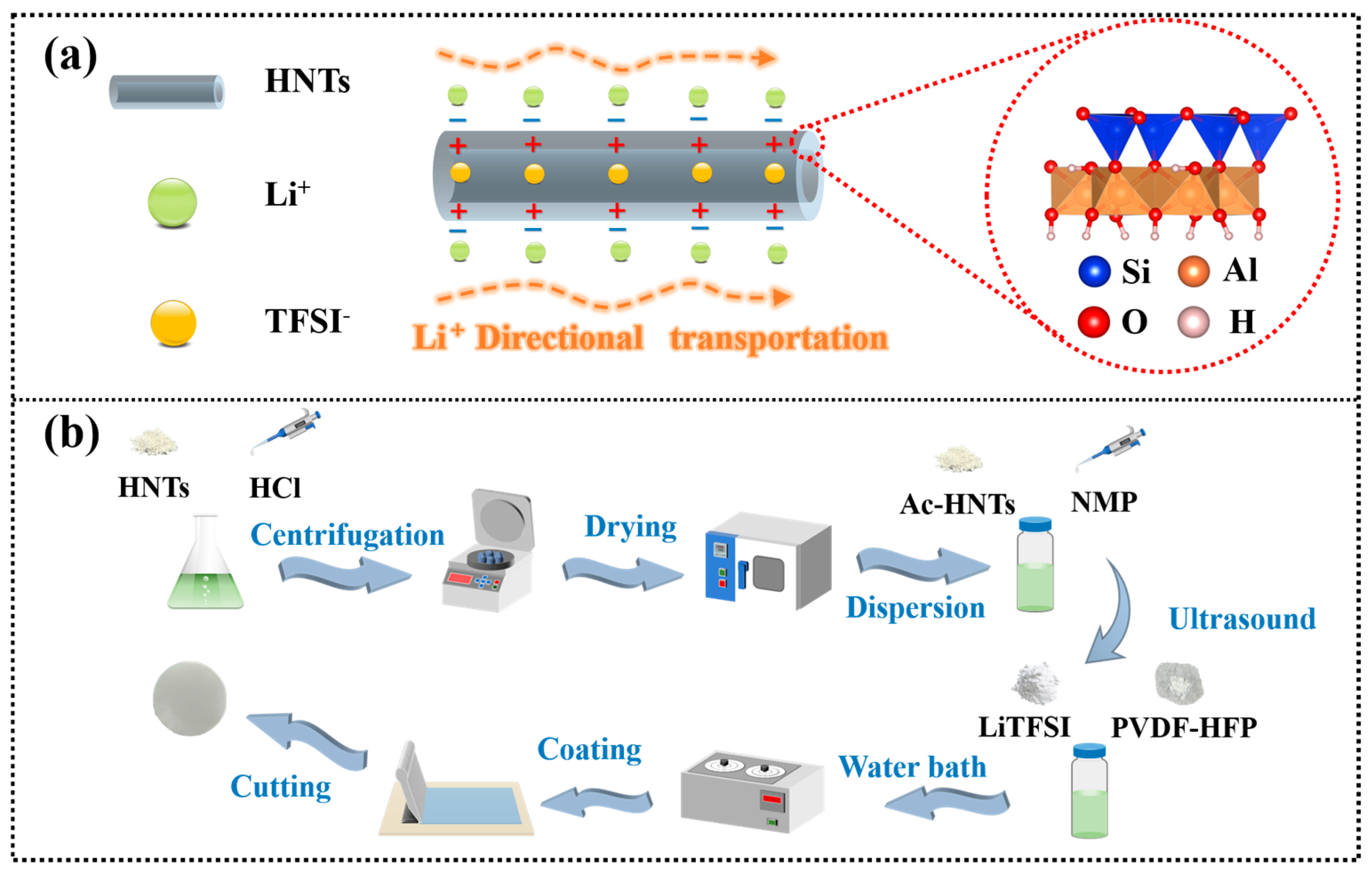
In this work, HNTs are employed to simultaneously enhance Li+ migration and restrict TFSI− anions by leveraging their inherent nanostructure and surface charges. As illustrated in Figure 1a, the outer wall of HNTs consists of a tetrahedral (Si–O) layer carrying a negative surface charge due to isomorphic substitution. The negatively charged exterior can modulate the coordination environment of lithium-ions and guide their movement along the nanotube surface, thereby providing efficient directional transport pathways to increase the ionic conductivity. Meanwhile, the inner lumen of HNTs, composed of an octahedra (Al–O) layer, typically exhibits positive charge originating from the protonation of aluminol (Al–OH) groups. The positively charged interior attracts TFSI− anions into the confined lumen, which slows down their migration and enhances the lithium transference number (tLi+). Although the use of halloysite nanotubes as fillers in polymer electrolytes has been previously reported, these studies primarily employed pristine, unmodified HNTs without systematic consideration of their surface purity or structural optimization [38]. It has been demonstrated that controlled acid treatment can effectively expand the lumen structure of HNTs [39]. Therefore, incorporating appropriately acid-etched HNTs into composite polymer electrolytes holds promise for further optimizing ion transport pathways and enhancing electrochemical performance. In this study, we introduce controlled acid etching as a strategy to optimize the surface chemistry and pore structure of HNTs. The influence of acid modification was systematically investigated, leading to the identification of an optimized etching condition that preserves the tubular morphology while effectively removing surface impurities. This structural optimization not only improves Li+ transport along the negatively charged outer walls but also opens the inner lumen for more effective TFSI− confinement, achieving a dual-functional enhancement of both ionic conductivity and lithium transference number. By establishing a clear relationship between etching degree and electrochemical performance, this work provides a new methodological framework for the functional utilization of HNTs in emerging energy storage applications. Incorporating these optimized HNTs significantly enhances both the ionic conductivity and lithium transference number of the PVDF-HFP-based CPE. Li||CPE||LFP cells assembled with this electrolyte exhibit excellent cycling stability and rate capability, offering a promising strategy for developing high-performance, low-cost quasi-solid-state lithium batteries.
Figure 1.
(a) Schematic illustration of the mechanism whereby the negatively charged outer surface (–) of HNTs facilitates Li+ transport while the positively charged inner lumen (+) anchors TFSI− anions. (b) Schematic diagram of the acid etching process of HNTs.
2. Materials and Methods
2.1. Materials
Halloysite nanotubes (HNTs, purity > 98%) were supplied by Guangdong Runwo Materials Technology Co., Ltd., Guangzhou, China, with the raw mineral sourced from Yulin, Guangxi, China. Poly(vinylidene fluoride-co-hexafluoropropylene) (PVDF-HFP, Mw = 400,000) was purchased from Sigma-Aldrich (St. Louis, MO, USA). Bis(trifluoromethanesulfonyl)imide lithium salt (LiTFSI, 99%) and N-methyl-2-pyrrolidone (NMP, AR, >99.0%) were purchased from Aladdin (Shanghai, China). Prior to use, PVDF-HFP and LiTFSI were dried under vacuum at 60 °C for 24 h, while all other chemicals were used as received without further purification.
2.2. Preparation of Acid-Etched HNTs
HNTs were etched with hydrochloric acid at different concentrations (6 M, 12 M) for varying durations. Specifically, 15 mL of HCl solution at each concentration was added to a three-neck flask containing 0.5 g of HNTs, followed by a hydrothermal reaction at 70 °C for 6 h. After the reaction, the products were centrifugally washed with deionized water and then dried in a vacuum oven for 24 h to completely remove moisture. The resulting products were labeled as HNTs-6M-6h and HNTs-12M-6h, respectively. Similarly, when the hydrothermal reaction time was extended to 12 h under otherwise identical conditions, the corresponding products were labeled as HNTs-6M-12h and HNTs-12M-12h.
2.3. Preparation of CPE
The fabrication process of CPE is schematically depicted in Figure 1b. The composite polymer electrolyte was prepared with a weight ratio of PVDF-HFP:LiTFSI:HNTs = 1:0.7:0.2. A total of 0.2 g HNTs without any pretreatment was dispersed in 5 mL of NMP solvent. The mixture was first sonicated for 30 min to prevent agglomeration, followed by magnetic stirring at room temperature for 12 h. Subsequently, 1 g of PVDF-HFP and LiTFSI each (equivalent to 70 wt% of the PVDF-HFP mass) were added to the dispersion. The mixture was continuously stirred for 12 h in a water bath at 55 °C, and the resulting mixture was labeled as PHL-1. Using the same procedure, HNTs-6M-12h and HNTs-12M-12h were separately added to prepare mixtures labeled as PHL-2 and PHL-3, respectively. For comparison, a HNTs-free polymer electrolyte (denoted as PL) was prepared following the same procedure without the addition of halloysite nanotubes. The mixtures were then cast onto glass plates using a doctor blade and dried in a vacuum oven at 60 °C for 12 h to completely remove the NMP solvent.
2.4. Materials Characterizations
The microstructure of HNTs, both before and after acid etching, was characterized by high-resolution transmission electron microscopy (TEM, FEI Tecnai G2 Spirit, Aarhus, Denmark). The crystal structure was analyzed by X-ray diffraction (XRD, Bruker D8 Advance, Tokyo, Japan) with Cu Kα radiation (λ = 1.5418 Å), a step size of 0.02°, and a scanning range of 10° to 80° (2θ). Functional groups were detected using Fourier transform infrared spectroscopy (FTIR, Nicolet iS10, Waltham, MA, USA) in attenuated total reflection (ATR) mode. Specific surface area was calculated based on the Brunauer–Emmett–Teller (BET) method using a physical adsorption analyzer (ASAP 2460 3.01, Lafayette, LA, USA). Inductively Coupled Plasma Optical Emission Spectrometry (ICP-OES, Agilent 730, Santa Clara, CA, USA) analysis was performed to determine the elemental composition of the supernatant obtained after centrifuging the acid-treated halloysite nanotube suspension. Zeta potential was measured using a Zetasizer Nano ZS90 (Malvern Instruments, Malvern, UK). HNTs (10 mg) were dispersed in 5 mL of deionized water via water bath ultrasonication for 5 min at room temperature. The suspension pH was adjusted as required using 0.1 M HCl or NaOH. Differential scanning calorimetry (DSC) measurements were performed using a TA Q20 (TA Instruments, New Castle, DE, USA) instrument under a nitrogen atmosphere. The samples were heated from −50 °C to 150 °C at a heating rate of 10 °C/min. The mechanical properties of the electrolyte membranes were evaluated using a CMT6103 (MTS Systems, Eden Prairie, MN, USA) universal testing machine. All samples were tested at a stretching rate of 1 mm/min at room temperature. The morphology and microstructure of the samples were examined using scanning electron microscopy (SEM, Hitachi SU8020, Tokyo, Japan). Raman spectroscopy (Thermo DXR2, Waltham, MA, USA) was performed on a confocal micro-Raman spectrometer, with a focus on the characteristic vibration peaks of TFSI− in the range of 700–800 cm−1.
2.5. Electrochemical Measurements
All CR2016-type coin cells were assembled in an argon-filled glove box, with both O2 and H2O levels strictly maintained below 0.1 ppm. For each electrolyte composition, at least three independent cells were fabricated and tested to ensure reproducibility. The LiFePO4 (LFP) cathode was prepared by casting a slurry consisting of LFP active material, conductive carbon black, and poly(vinylidene fluoride) (PVDF) binder in a weight ratio of 8:1:1 onto an aluminum current collector, followed by drying in a vacuum oven at 120 °C for 12 h. Lithium metal foil was used as the anode. During assembly, 5 μL of liquid electrolyte—composed of 1 M LiTFSI in a mixture of ethylene carbonate (EC)–diethyl carbonate (DEC)–dimethyl Carbonate (DMC) (1:1:1 by volume) with 5% fluoroethylene carbonate (FEC) added as a film-forming additive—was dropped between the positive and negative electrodes. The assembled cells were allowed to stand at room temperature for 12 h before all electrochemical tests were conducted.
Electrochemical impedance spectroscopy (EIS) was performed using a CHI760E electrochemical workstation (Shanghai Chenhua Instrument Co., Ltd., Shanghai, China) over a frequency range of 10−1 to 106 Hz with an AC perturbation voltage of 10 mV. The ionic conductivity of the CPE was evaluated using symmetric cells with a stainless steel (SS)||CPE||SS configuration. The ionic conductivity (σ) was calculated according to the formula:
where L is the thickness of the electrolyte membrane, R is the bulk resistance, and S is the effective contact area between the electrolyte and the stainless steel spacer. The lithium transference number was determined by combining chronoamperometry with AC impedance measurements, using Li||CPE||Li symmetric cells at room temperature. TLi+ was calculated using the formula:
where I0 and Is represent the initial and steady-state currents, respectively, ΔV is the applied DC bias (5 mV), and R0 and Rs are the interfacial resistances before and after polarization. The cycling performance and rate capability of the assembled Li||CPE||LFP cells were evaluated by galvanostatic charge–discharge tests at room temperature using a Neware battery testing system (BTS software v8.0, Neware Technology Limited, Shenzhen, China).
σ = L/(R × S),
tLi+ = [Is × (ΔV − I0R0)]/[I0 (ΔV − IsRs)],
3. Results and Discussion
3.1. TEM Characterization of HNTs
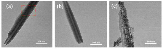
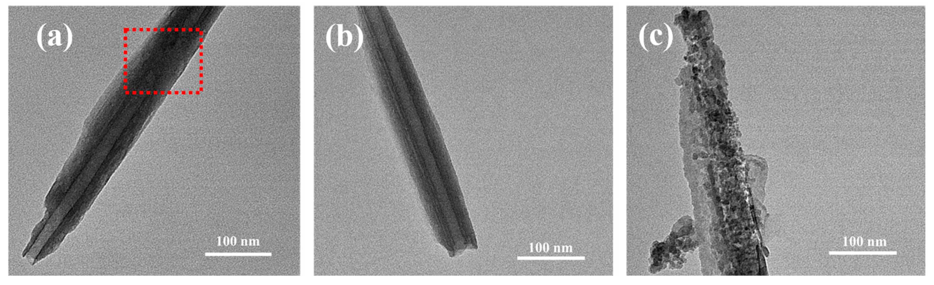
The morphology of HNTs before and after acid-etching treatment was detected through TEM. As reflected in Figure 2a, the pristine HNTs displayed typical nanotubular morphologies, while some distinct dark blockages are present within the lumen, indicating that the inner cavities of pristine HNTs are partially occupied by impurities. This blockage is expected to limit their effective utilization as nanocontainers and ion-transport channels. Figure 2b displays the TEM image of HNTs treated with 6M-12h acid etching, demonstrating the ideal effect of moderate etching. Compared with pristine HNTs, the most notable change is that the lumen becomes clear and unobstructed, with internal blockages effectively removed. Figure 2c presents the TEM image of HNTs subjected to 12M-12h acid treatment, revealing the adverse effects of excessive etching. Under overly harsh reaction conditions, the acid not only dissolves the target aluminum–oxygen layer but further corrodes the originally relatively stable silicon–oxygen layer, leading to the collapse and destruction of the overall nanotube structure and the loss of their unique tubular morphology. This result clarifies the processing window for acid etching, indicating that excessively high acid concentrations or prolonged reaction times can damage the structure, thereby providing critical guidance for optimizing process parameters.
Figure 2.
TEM images of HNTs with different degrees of acid etching: (a) pristine HNTs, with the red box highlighting the presence of blockages within the lumen. (b) HNTs-6M-12h. (c) HNTs-12M-12h.
3.2. XRD and FTIR Analysis
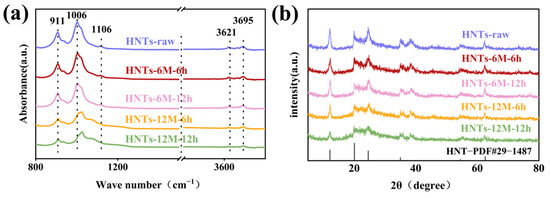
Figure 3a shows the XRD patterns of HNTs with different acid etching degrees. As the HCl concentration and etching duration increase, the peak intensities corresponding to the HNTs structure gradually decrease. When etched with 12 M HCl for 12 h, the peak intensities are significantly reduced, indicating potential structural collapse [40].
Figure 3.
(a) XRD patterns and (b) FTIR spectra of HNTs with varying degrees of acid etching.
Figure 3b presents the FTIR spectra of HNTs with varying acid etching degrees. For the untreated HNTs, the peaks at 3695 cm−1 and 3621 cm−1 correspond to the O–H stretching vibrations of the inner-surface Al–OH groups. The absorption peak at 911 cm−1 is attributed to the deformation vibration of Al–O–H on the inner surface [41]. The absorption peaks at 1106 cm−1 and 1006 cm−1 correspond to the Si–O–Si vibrations on the outer surface [42]. When the HCl concentration is 6 M, the absorption peak intensities for Si–O–Si and Al–OH slightly decrease, while the peaks at 3695 cm−1 and 3621 cm−1 show no significant change. This suggests that after 12 h of etching with 6 M HCl, partial corrosion of the inner walls may have occurred, but the structure remains largely intact. When the HCl concentration increases to 12 M, the vibration absorption peaks for Si–O–Si, Al–OH, and inner-surface O–H are significantly reduced. Additionally, the characteristic peak near 1006 cm−1, assigned to the Si–O stretching vibration, shifts to higher wavenumbers. This clearly indicates that the strong acid treatment has disrupted the originally stable silicon–oxygen tetrahedral framework in HNTs, leading to alterations in the chemical environment of the Si–O bonds [43,44].
3.3. Characterization of HNTs and HNTs-Based Composite Polymer Electrolytes
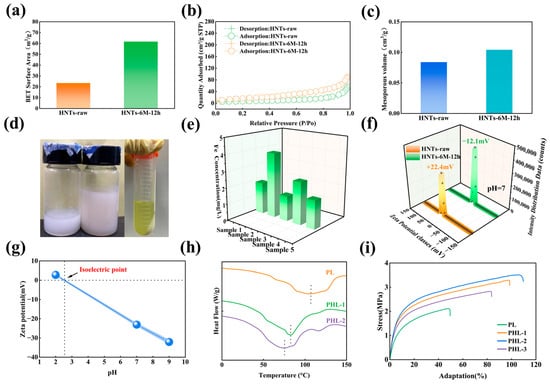
To determine the influence of acid etching upon the specific surface area of HNTs, BET method using nitrogen adsorption/desorption isotherms. As illustrated in Figure 4a, b, HNTs-6M-12h possesses a specific surface area of 60 m2/g, nearly three times that of the pristine HNTs (23 m2/g). As shown in Figure 4c, the mesopore volume (2–50 nm) of HNTs increases from 0.084 cm3/g for pristine HNTs to 0.104 cm3/g for HNTs-6M-12h, corresponding to an increase of approximately 23.8%. This substantial increase in pore volume is consistent with the TEM observations, which reveal the removal of “dark blockages” from the HNTs lumen, confirming that the internal channels become more accessible for anion confinement. The enlarged mesopore volume offers additional space for TFSI− anions to enter and interact with the inner Al–OH groups. Furthermore, the study confirmed that the acid etching process effectively removes surface impurities from HNTs. The presence of surface impurities on HNTs is visually reflected in the color of the electrolyte solutions. Figure 4d demonstrates that the solution with pristine HNTs appears faint yellow, whereas the one with HNTs-6M-12h is purely white. Moreover, the yellowish color of the post-etching supernatant likely results from the dissolution of iron and other impurities originally present on the HNTs surface. The presence of dissolved iron in the supernatant was quantitatively verified by ICP-OES analysis (Figure 4e). To eliminate chance variations, five parallel samples from the same batch were analyzed. Prior to measurement, each sample was diluted eight-fold with deionized water. After multiplying by the dilution factor, the average iron concentration in the original supernatant was determined to be 18.864 ± 7.890 mg/L. Based on the mass of HNTs (0.5 g) and volume of HCl (15 mL) used, this corresponds to the removal of 0.566 ± 0.237 mg of iron per gram of raw HNTs. The removal of such surface impurities also influences the surface charge of the HNTs. As shown in Figure 4f, the pristine HNTs exhibited a positive Zeta potential of 22.4 mV under neutral conditions (pH 7), which indicates that the untreated sample possessed positive surface charge at the exterior surface, contrary to the generally expected negative charge. This anomalous phenomenon could be attributed to impurities such as iron-containing species adhered to the outer walls, which would hinder the efficiency of Li+ migration along HNTs. After proper acid etching, the HNTs-6M-12h exhibited the typical negative Zeta potential (−12.1 mV) of purified HNTs. The determination of the isoelectric point illustrated in Figure 4g further corroborates the aforementioned surface chemical transformation. The Zeta potential versus pH curve shifts from a slightly positive value at pH 2 to strongly negative values at pH 7 and pH 9, which indicates that the isoelectric point of HNTs-6M-12h is around pH 3. This result reveals that a positive Zeta potential would only be exhibited under sufficiently acidic conditions due to protonation of the outer surface. In all other environments, the Zeta potential of the modified HNTs remains negative, further verifying the fact that proper acid etching imparts a negative charge to the exterior surface of HNTs [45]. DSC measurements were conducted to investigate the crystallinity of the electrolyte membranes, and the corresponding thermograms are presented in Figure 4h. The melting point of the HNTs-free electrolyte (PL) is 104.3 °C. Upon incorporation of pristine HNTs, the melting point of PHL-1 decreases significantly to 82.3 °C, indicating that the addition of HNTs effectively reduces the crystallinity of the PVDF-HFP matrix and enhances segmental motion. For PHL-2 containing acid-etched HNTs, the melting point is 74.4 °C, showing only a slight further reduction. This marginal decrease suggests that the primary role of acid etching is not to further lower the crystallinity, but rather to remove surface impurities and enlarge the pore structure of HNTs, thereby contributing to the enhanced dual-functional ion transport mechanism. Mechanical properties of the CPEs were evaluated by tensile testing (Figure 4i). The pristine PL exhibits a tensile strength of 2.116 Mpa and a tensile modulus of 1.494 Mpa. Incorporation of pristine HNTs (PHL-1) substantially enhances both strength to 3.292 Mpa and modulus to 5.922 Mpa, indicating effective matrix reinforcement. For PHL-2 containing acid-etched HNTs (HNTs-6M-12h), tensile strength further increases to 3.51 Mpa with a modulus of 6.806 Mpa. This enhancement might be attributed to improved interfacial adhesion resulting from acid etching. Removal of surface impurities such as metal oxides, confirmed by ICP-OES and Zeta potential analysis, likely results in a cleaner, negatively charged HNT surface that promotes stronger polymer-filler interactions and more efficient stress transfer. In contrast, PHL-3 incorporating over-etched HNTs (HNTs-12M-12h) exhibits a significant decrease in both tensile strength (2.828 Mpa) and modulus (3.308 Mpa) compared to PHL-2, with values falling below those of PHL-1. This deterioration aligns with the structural degradation observed in TEM, XRD and FTIR analyses, where excessive acid etching compromises the tubular integrity of HNTs.
Figure 4.
(a) Surface area, (b) N2 adsorption–desorption isotherms and (c) mesopore volume (2–50 nm) data of raw HNTs and HNTs-6M-12h. (d) Visual comparison: electrolyte solutions prepared with HNTs-6M-12h (left), HNTs (middle), and the supernatant obtained after centrifugation of acid-etched HNTs (right). (e) The concentration of iron ions in the supernatant after acid etching. (f) Zeta potential-pH curve and isoelectric point determination of acid-etched HNTs. (g) Zeta potential of HNTs and HNTs-6M-12h in aqueous solution at pH = 7. (h) DSC thermograms of PL, PHL-1 and PHL-2 electrolyte membranes. (i) Stress–strain curves of PL, PHL-1, PHL-2 and PHL-3 electrolyte membranes.
3.4. Morphological Evolution and Ion Coordination Environment
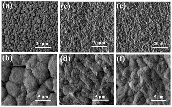
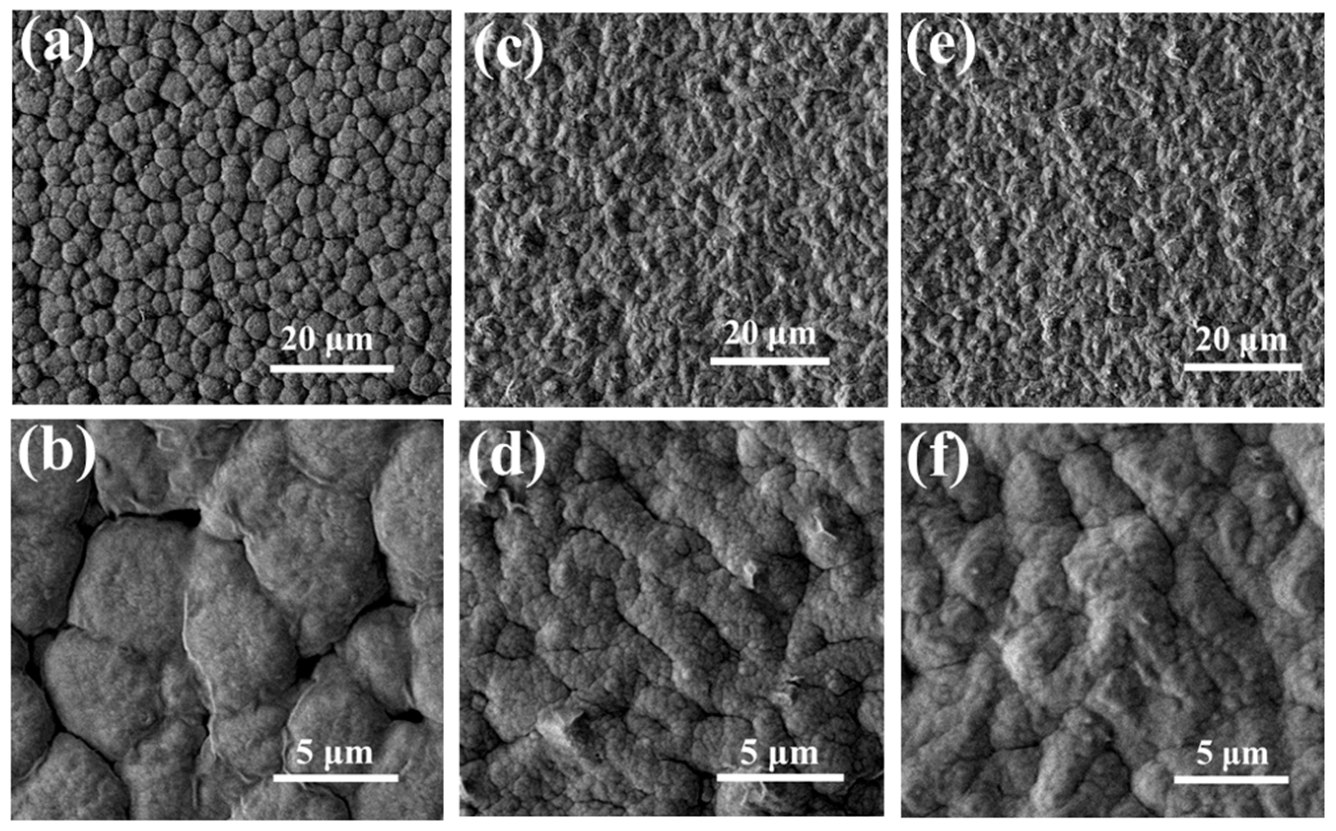
Figure 5 shows that the HNTs-free polymer exhibits a structure composed of numerous spherulites. After incorporating HNTs, the size of the spherulites decreased, and a large number of spherical secondary structures appeared within them. This can be attributed to the fact that HNTs provide additional nucleation sites during the phase separation and crystallization of PVDF-HFP, which effectively restricts the growth of crystalline regions, increases the relative proportion of amorphous regions. The influence induced by HNTs upon the crystallinity of PVDF-HFP would also contribute to enhancing the ionic conductivity of the electrolyte. Moreover, the SEM images reveal a uniform distribution of HNTs within the PVDF-HFP matrix, indicating good interfacial compatibility between HNTs and PVDF-HFP. The morphology of the polymer containing HNTs-6M-12h is essentially consistent with that of the polymer containing unmodified HNTs, indicating that a moderate acid-etching process does not compromise the favorable interfacial compatibility between HNTs and polymer matrix.
Figure 5.
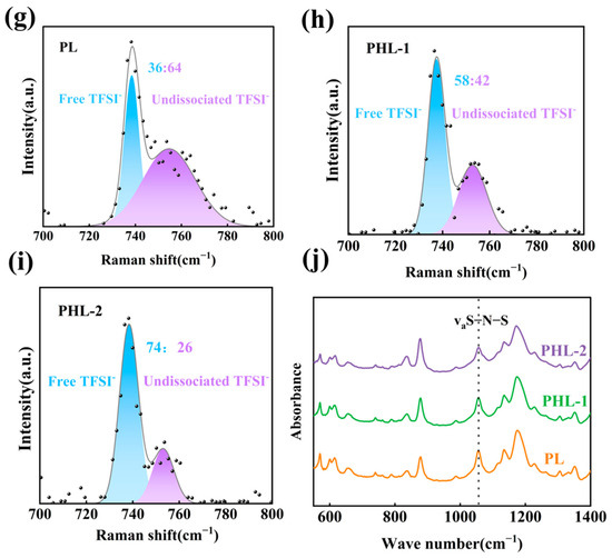
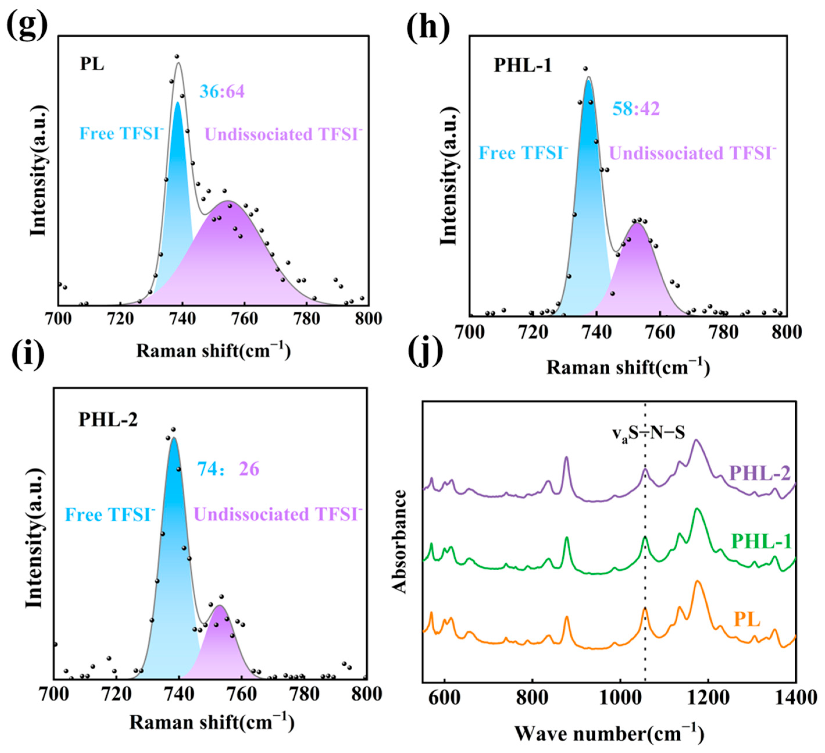
SEM images of PVDF-HFP polymer membranes (a,b) PL (without HNTs), (c,d) PHL-1 (with pristine HNTs) and (e,f) PHL-2 (with HNTs-6M-12h). Raman spectra of polymer electrolyte membranes (g) PL, (h) PHL-1, and (i) PHL-2; FTIR spectra of polymer electrolyte membranes (j) PL, PHL-1, and PHL-2.
Raman and FTIR spectroscopy were employed to investigate the interaction between TFSI− anions and HNTs. As shown in Figure 5g–i, a comparison of the Raman spectra in the range of 700–800 cm−1 among the HNTs-free (PL), unmodified HNTs-containing (PHL-1), and HNTs-6M-12h-containing (PHL-2) electrolyte reveals a distinct change in the characteristic peak profiles of TFSI−. After incorporating pristine HNTs, the ratio of free TFSI− anions to undissociated ion pairs increased from 36:64 to 58:42. This can be attributed to the tubular structure of HNTs and the positive charge on their inner surface, which partially anchors TFSI− anions. For PHL-2 containing etched HNTs, the ratio further increased to 74:26. This enhanced dissociation is ascribed to the synergistic effect of acid etching, where the increased specific surface area and pore volume, together with the removal of surface impurities, allow the negatively charged outer surface to attract Li+ more effectively, while the accessible inner lumen provides stronger confinement for TFSI− anions. This dual-function mechanism, Li+ attraction by the outer surface and TFSI− confinement by the inner lumen, weakens the coordination interaction between Li+ and TFSI−, thereby increasing the proportion of free TFSI− anions. This promotion of LiTFSI salt dissociation contributes to the higher ionic conductivity.
FTIR spectra (Figure 5j) provide complementary insights. The band at ~1058 cm−1, assigned to the S-N-S antisymmetric stretching vibration of TFSI−, shows a gradual intensity decrease upon HNTs addition, with the most pronounced reduction observed for PHL-2. Since the total TFSI− concentration is identical across all samples, the observed intensity decrease cannot be attributed to concentration variations, but rather suggests an altered vibrational environment of TFSI−. This change indirectly implies that a portion of TFSI− anions may be confined within the HNTs lumen, where potential interaction with the inner Al–OH groups could modify the S–N–S vibrational mode, thereby reducing the infrared absorption efficiency. The enhanced reduction in PHL-2 indicates that acid-etched HNTs, with enlarged pore volume and exposed inner surface, provide more effective TFSI− confinement.
3.5. Ion Conductivity and Lithium Transference Number of Different Quasi-Solid Electrolyte Membranes
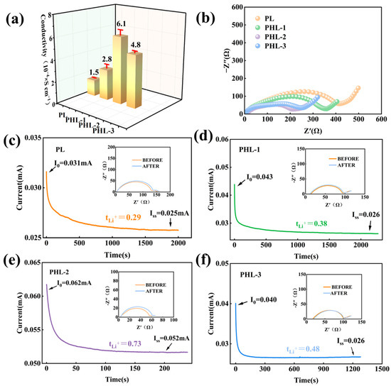
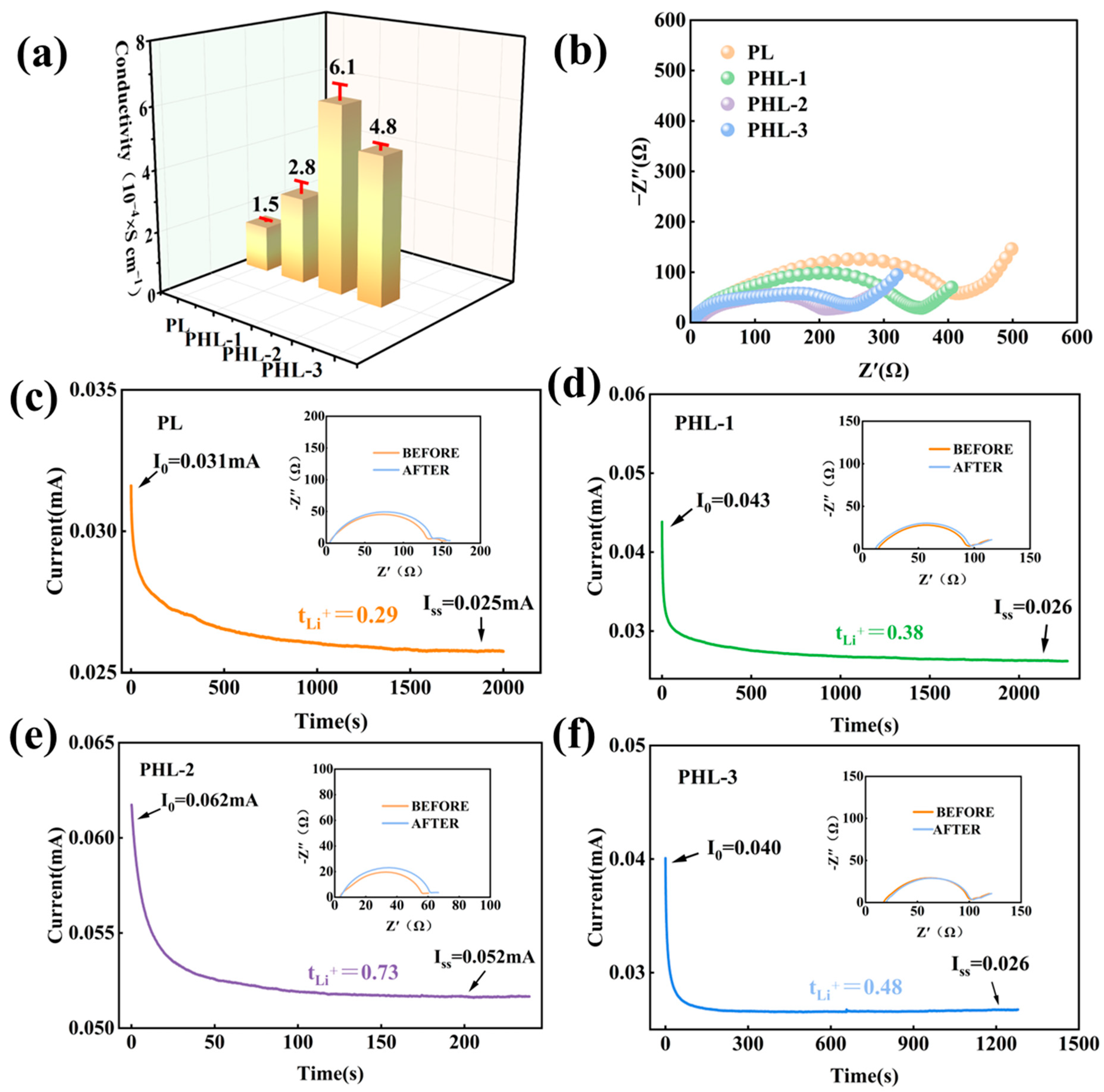
Figure 6a compares the ionic conductivity of CPE with and without HNTs fillers, calculated from the EIS results of SS||CPE||SS cells. Incorporating unmodified HNTs into the PVDF-HFP-based electrolyte nearly doubled the ionic conductivity, from 1.5 × 10⁻⁴ S⋅cm−1 to 2.8 × 10⁻⁴ S⋅cm−1. This improvement aligns with the previously discussed reduction in the crystallinity of the PVDF-HFP matrix induced by HNTs, as the enhanced segmental motion of polymer chains in amorphous regions facilitates lithium-ion transport. The PHL-2 sample, containing HNTs-6M-12h, exhibits the highest ionic conductivity of 6.1 × 10⁻⁴ S⋅cm−1. This confirms the aforementioned hypothesis that moderate acid etching removes impurities from the HNTs outer surface and converts its charge to negative, thereby more effectively guiding lithium-ion transport along the nanotubes and providing an efficient long-range conduction pathway. Conversely, excessive acid etching degrades the tubular structure of HNTs, diminishing their ability to facilitate ion conduction. Consequently, the PHL-3 sample showed a lower conductivity of 4.8 × 10⁻⁴ S⋅cm−1. Figure 6b presents the EIS results measured for Li||CPE||LFP cells employing the four kinds of electrolytes. It can be observed that the relative trend in charge transfer resistance among the four cells is consistent with the ionic conductivity of their corresponding electrolytes. This correlation arises because electrolytes with higher conductivity could more rapidly compensate for interfacial concentration gradients during charge/discharge processes, thereby significantly suppressing concentration polarization and bringing the charge transfer reaction closer to the thermodynamic equilibrium state.
Figure 6.
(a) Comparison of ionic conductivity for PL, PHL-1, PHL-2, and PHL-3; (b) EIS results of Li||CPE||LFP cells using PH, PHL-1, PHL-2, and PHL-3 electrolytes; (c–f) Lithium transference number test results for PL, PHL-1, PHL-2, and PHL-3, respectively.
Figure 6c–f present the lithium transference number test results for different electrolytes. Regardless of the type of HNTs added, all three HNTs-containing electrolytes exhibited an increase in lithium transference number. For PHL-2 based on moderately acid-etched HNTs-6M-12h, the lithium transference number significantly increases from 0.38 for pristine PHL-1 to 0.73. This indicates that the clean and enlarged nanotube channels obtained through acid etching effectively promote the selective transport of Li+. However, for PHL-3 using excessively acid-etched HNTs-12M-12h, the lithium transference number decreases to 0.48. This is attributed to the collapse of the tubular structure of HNTs, which disrupts the continuity of the ion conduction pathways, further confirming the critical impact of etching degree on the microstructure and transport properties of the electrolyte.
3.6. Influence of Acid-Etching Degree on the Battery Performance of Composite Electrolytes
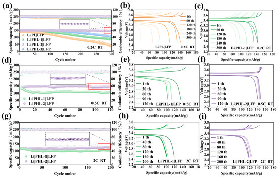
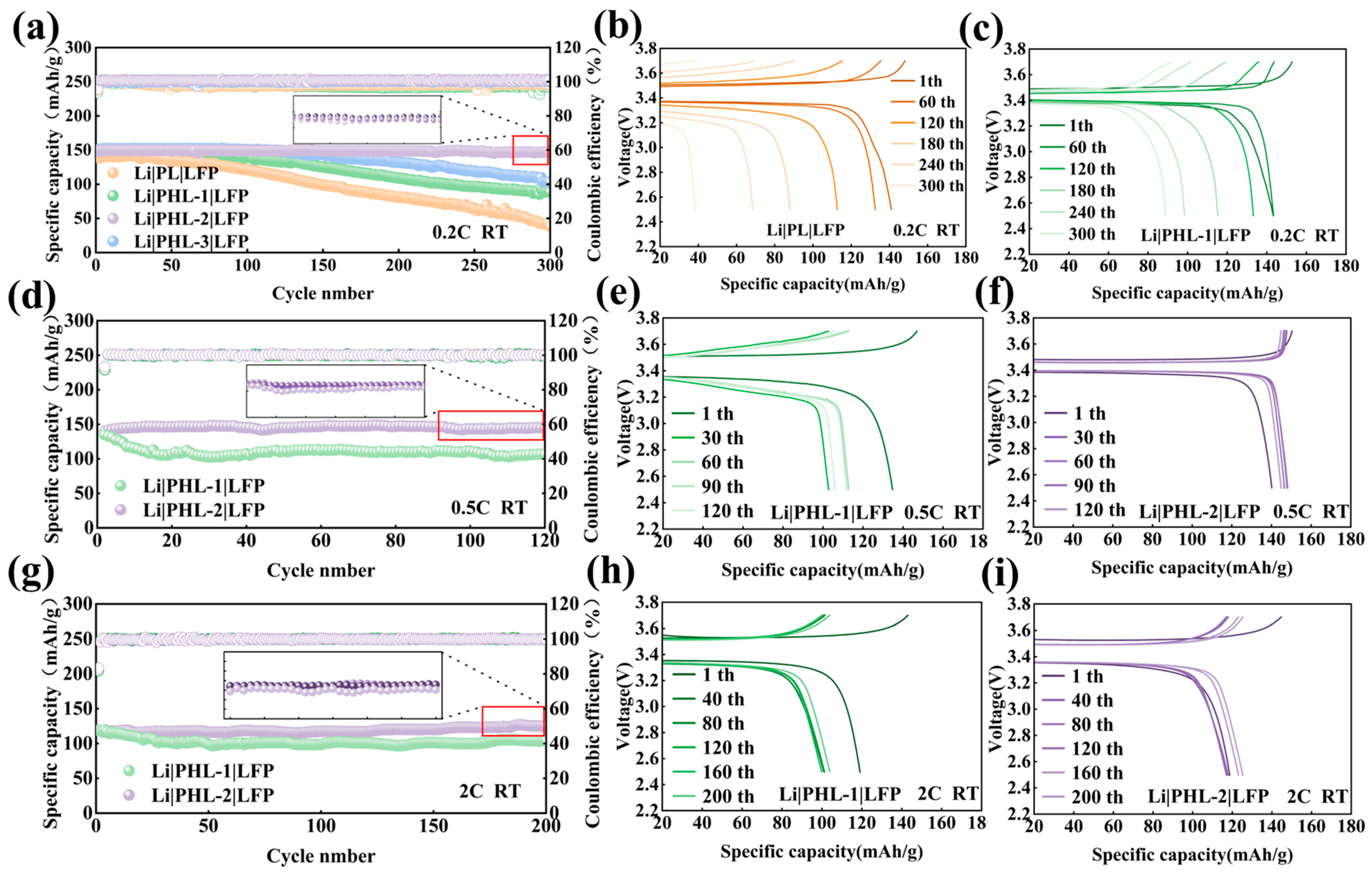
To systematically evaluate the effect of acid-treated HNTs on the electrochemical performance of PVDF-HFP-based composite electrolytes, a series of Li||CPE||LFP cells were assembled. Their long-term cycling stability, high-rate tolerance, and reaction kinetics were comprehensively investigated. Figure 7a compares the long-term cycling performance of cells employing four different electrolytes at 0.2C over 300 cycles at room temperature. The cell using the HNTs-free electrolyte (PL) exhibited severe capacity fading, retaining only 27.2% of its initial capacity. Upon incorporation of pristine HNTs (PHL-1), the cycling stability was markedly improved, with the capacity retention increasing to 62%. Notably, the cell based on moderately acid-treated HNTs-6M-12h (PHL-2) demonstrated impressive cycling performance, delivering a capacity retention as high as 99.25%, which was also substantially superior to that of the excessively acid-treated sample (PHL-3, 68.3%). This performance is also competitive with those reported in the literature [46,47,48,49,50]. The corresponding charge–discharge voltage profiles in Figure 7b, c provide direct kinetic insight into these cycling behaviors. As shown in Figure 7b, the PL cell underwent pronounced degradation of the voltage profiles during cycling, characterized by a continuously enlarged separation between the charge and discharge curve and a notably shortening of the plateau. This behavior reflects rapid polarization growth and progressive interfacial resistance accumulation. In comparison, the PHL-1 cell in Figure 7c exhibited much more moderate changes in plateau separation, suggesting that the incorporation of halloysite nanotubes improves ion transport, thereby partially alleviating polarization.
Figure 7.
(a) Long-term cycling performance at 0.2C of Li||CPE||LFP cells with PL, PHL-1, PHL-2,and PHL-3 electrolytes; (b,c) charge–discharge voltage–capacity profiles of Li||CPE||LFP cells with (b) PL and (c) PHL-1 electrolytes at 0.2C. (d) Long-term cycling performance of Li||CPE||LFP cells with PHL-1 and PHL-2 electrolytes at 0.5C. Corresponding charge–discharge voltage–capacity profiles of Li||CPE||LFP cells with (e) PHL-1 and (f) PHL-2 electrolytes at 0.5C. (g) Long-term cycling performance of Li||CPE||LFP cells with PHL-1 and PHL-2 electrolytes at 2C. Corresponding charge–discharge voltage–capacity profiles of Li||CPE||LFP cells with (h) PHL-1 and (i) PHL-2 electrolytes at 2C. The insets in (a,d,g) display cycling data from three parallel PHL-2 cells, demonstrating the reproducibility of the PHL-2 electrolyte.
Additionally, the cycling behaviors of the PHL-1 and PHL-2 cells were also tested at 0.5C and 2C in order to further investigate the impact of moderate acid etching on the enhancement of electrochemical performance in CPE by HNTs fillers. As illustrated in Figure 7d, the PHL-2 cell delivers an average discharge capacity of 145.72 mAh/g over 120 cycles at 0.5C, which is significantly higher than that of the PHL-1 (110.08 mAh/g). Moreover, the corresponding voltage profiles presented in Figure 7e,f further reveal that the charge–discharge plateau separation of the PHL-1 cell increases markedly with cycling, whereas the ones of the PHL-2 cell remain highly overlapped. A similar conclusion was drawn from the 200-cycle charge/discharge test at 2C, where PHL-2 delivered a higher and more stable specific capacity, while PHL-1 exhibited a relatively lower capacity with noticeable fluctuations. To ensure the reproducibility of the battery performance, at least three independent cells were tested for each electrolyte composition, as demonstrated in the insets in Figure 7a,d,g, which present the specific capacity values of three parallel PHL-2 samples at the end of cycling. For instance, the inset in Figure 7a displays the last 20 cycles of three parallel cells using the PHL-2 electrolyte at 0.2C. Within this cycling range, the average discharge capacities obtained from the three cells were 146.94, 143.46, and 145.42 mAh/g, respectively, yielding a mean value of 145.27 ± 1.74 mAh/g.
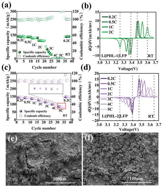
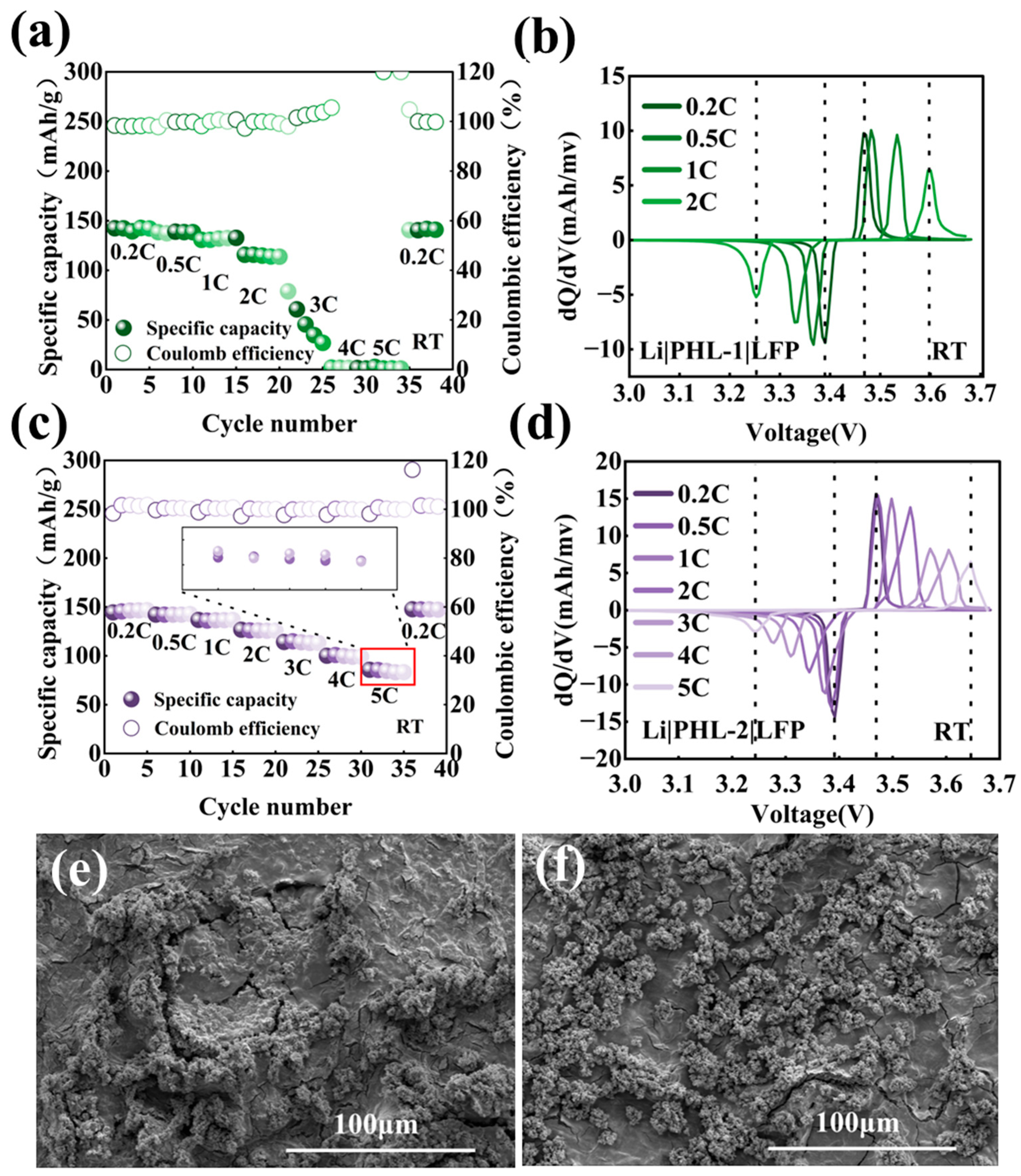
The rate capability and differential capacity analyses shown in Figure 8a–d further elucidate the performance disparity. As the rate increases from 0.2C to 5C, the PHL-2 cell exhibits a much more gradual capacity decay, with the discharge capacity decreasing from 144.48 mAh/g to 85.72 mAh/g. To demonstrate the reproducibility of the rate performance, data from three parallel Li||CPE||LFP cells using the PHL-2 electrolyte at 5C have been included in Figure 8c. The average discharge capacities of the three cells were 84.45, 85.55, and 87.18 mAh/g at 5C, respectively, yielding a mean value of 85.73 ± 1.37 mAh/g. The corresponding differential capacity curves reveal that the redox peaks associated with the LFP lithiation and delithiation reactions shift in potential with an increasing rate, which is a direct manifestation of electrode polarization. Specifically, the reduction peak of the PHL-1 cell shifts from 3.46 V at 0.2C to 3.6 V at 2C, corresponding to a potential shift of 140 mV. Moreover, the dQ/dV peaks rapidly diminish and eventually disappear at high rates of 3C and above, indicating severely compromised reaction reversibility. In contrast, the PHL-2 cell exhibits a much smaller peak shift, with the reduction peak shifting from 3.46 V to 3.53 V, corresponding to approximately 70 mV. Notably, well-defined and complete redox peaks are still preserved even at 5C, directly confirming its superior reaction kinetics and reduced polarization under high-rate operation.
Figure 8.
(a,c) Rate performance of Li||CPE||LFP cells with PHL-1 (green dots) and PHL-2 (purple dots) electrolytes from 0.2C to 5C. (b,d) Corresponding dQ/dV–voltage curves during rate tests. The inset in (c) displays the discharge capacities at 5C from three parallel PHL-2 cells, demonstrating the reproducibility of the rate capability. SEM images of the Li surface from Li||CPE||LFP cells after 50 cycles at 0.2C; (e) PHL-1 electrolyte; (f) PHL-2 electrolyte.
Overall, the reduced capacity fading and smaller potential shifts collectively demonstrate that the PHL-2 cell possesses more favorable lithium-ion transport kinetics and a lower overall polarization. This advantage fundamentally originates from the effective enhancement of the ionic conductivity and lithium transference number of the composite electrolyte induced by optimal HNTs. Uniformly dispersed within the PVDF-HFP matrix, HNTs-6M-12h facilitate lithium-ion migration by their negatively charged outer surface, while their open inner lumen can accommodate TFSI− anions and restrict their movement. This dual function not only enhances the flux and uniformity of lithium-ions within the CPE during battery operation but also ensures that charge transport under high current densities is predominantly governed by lithium-ions. SEM images of the lithium metal surfaces after cycling provide visual evidence for evaluating the performance of HNTs as electrolyte fillers. As shown in Figure 8e, the lithium electrode retrieved from the cell using the PHL-1 electrolyte, which contains pristine HNTs, exhibits an uneven surface with noticeable protrusions after 50 cycles at 0.2C. In contrast, the lithium surface from the cell employing the PHL-2 electrolyte incorporating acid-etched HNTs (HNTs-6M-12h) displays a relatively smooth and uniform morphology, as depicted in Figure 8f. The morphology of lithium metal is determined by the nucleation process during lithium deposition, which relies on the homogeneity and efficiency of lithium transportation within the electrolyte. The SEM images align with previous proposition that the PHL-2 electrolyte exhibits higher ionic conductivity and lithium transference number of the PHL-2 electrolyte. In summary, the optimized HNTs-based electrolyte enables more homogeneous lithium deposition and enhances interfacial stability during prolonged cycling and rate test.
4. Conclusions
This work demonstrates that rational structural modification of natural halloysite nanotubes (HNTs) enables their effective use as a low-cost, multifunctional filler in PVDF-HFP-based composite polymer electrolytes. The unique dual-charge architecture of HNTs—with a negatively charged outer surface and a positively charged inner lumen—plays a decisive role in simultaneously addressing two persistent limitations of conventional CPEs: low ionic conductivity and inadequate lithium-ion transference number. Controlled acid etching was applied to optimize the mineral’s structure, effectively removing surface impurities such as iron oxides and enlarging the inner lumen while preserving its tubular morphology. This treatment enhances the negative charge on the exterior, facilitating Li+ migration along the nanotube surface, and strengthens the confinement of TFSI− anions within the positively charged interior. Additionally, the incorporation of HNTs reduces the crystallinity of the PVDF-HFP matrix and promotes lithium salt dissociation, further contributing to improved ion-transport pathways. The optimally etched HNTs (HNTs-6M-12h) enabled the resulting CPE to achieve an ionic conductivity of 6.1 × 10⁻⁴ S⋅cm−1 and a Li+ transference number of 0.73. Electrochemical validation using Li||CPE||LiFePO4 cells confirmed the efficacy of this approach, with cells exhibiting excellent cycling stability (99.25% capacity retention after 300 cycles at 0.2C), remarkable rate capability (85.72 mAh/g at 5C), and significantly reduced polarization under high current densities. Overall, this work highlights the considerable potential of naturally abundant clay minerals such as halloysite. Through tailored mineralogical modification, HNTs can be transformed into sustainable, economical, and high-performance functional fillers, offering a promising materials strategy for next-generation quasi-solid-state batteries.
Author Contributions
Conceptualization, K.W. and Y.L.; methodology, K.W. and X.L. (Xiaowei Li); validation, K.W. and X.L. (Xiaowei Li); formal analysis, Y.L.; investigation, Y.L., X.L. (Xuehui Li) and P.C.; resources, G.L. and L.L.; writing—original draft preparation, Y.L and K.W.; writing—review and editing, Y.L, K.W. and X.L. (Xiaowei Li); visualization, Y.L.; supervision, L.L.; project administration, G.L.; funding acquisition, G.L. All authors have read and agreed to the published version of the manuscript.
Funding
This research was funded by National Natural Science Foundation of China, grant number 42572042.
Data Availability Statement
The original contributions presented in this study are included in the article. Further inquiries can be directed to the corresponding authors.
Acknowledgments
During the preparation of this manuscript, the authors used DeepSeek-V3.2 AI Assistant for the purposes of polishing the language expression. The authors have reviewed and edited the output and take full responsibility for the content of this publication.
Conflicts of Interest
The authors declare no conflicts of interest.
References
- Yuan, P.; Tan, D.; Annabi-Bergaya, F. Properties and applications of halloysite nanotubes: Recent research advances and future prospects. Appl. Clay Sci. 2015, 112–113, 75–93. [Google Scholar] [CrossRef] [Scilit]
- Gkouma, E.; Gianni, E.; Avgoustakis, K.; Papoulis, D. Applications of halloysite in tissue engineering. Appl. Clay Sci. 2021, 214, 106291. [Google Scholar] [CrossRef] [Scilit]
- Senyel, M.; Dike, A.S. Contribution of silane modification of halloysite nanotube to its poly (butylene terephthalate)-based nanocomposites: Structural, mechanical and thermal properties. Polym. Bull. 2024, 81, 9851–9870. [Google Scholar] [CrossRef] [Scilit]
- Yah, W.O.; Xu, H.; Soejima, H.; Ma, W.; Lvov, Y.; Takahara, A. Biomimetic dopamine derivative for selective polymer modification of halloysite nanotube lumen. J. Am. Chem. Soc. 2012, 134, 12134–12137. [Google Scholar] [CrossRef] [Scilit] [PubMed]
- Yuan, P.; Southon, P.D.; Liu, Z.; Green, M.E.R.; Hook, J.M.; Antill, S.J.; Kepert, C.J. Functionalization of Halloysite Clay Nanotubes by Grafting with γ-Aminopropyltriethoxysilane. J. Phys. Chem. C 2008, 112, 15742–15751. [Google Scholar] [CrossRef] [Scilit]
- Gray-Wannell, N.; Cubillas, P.; Aslam, Z.; Holliman, P.J.; Greenwell, H.C.; Brydson, R.; Delbos, E.; Strachan, L.J.; Fuller, M.; Hillier, S. Morphological features of halloysite nanotubes as revealed by various microscopies. Clay Miner. 2023, 58, 395–407. [Google Scholar] [CrossRef] [Scilit]
- Hillier, S.; Brydson, R.; Delbos, E.; Fraser, T.; Gray, N.; Pendlowski, H.; Phillips, I.; Robertson, J.; Wilson, I. Correlations among the mineralogical and physical properties of halloysite nanotubes (HNTs). Clay Miner. 2018, 51, 325–350. [Google Scholar] [CrossRef] [Scilit]
- Mekhania, Z.A.; Iggui, K.; Benkacher, N.; Benhamida, A.; Bengourna, N.; Djermoune, A.; Merzeg, F.A.; Satha, H.; Layachi, A. Inner- and outer-surface modification of Algerian halloysite nanotubes with triethoxy(octyl)silane and caffeic acid for enhanced functional properties. Clay Miner. 2025, 60, 247–258. [Google Scholar] [CrossRef] [Scilit]
- Verduga, C.V.; Henderson, J.D.; Workentin, M.S. Clickable halloysite nanotubes for interfacial strain promoted azide-alkyne cycloaddition of Au25 nanoclusters. Appl. Clay Sci. 2025, 278, 108013. [Google Scholar] [CrossRef] [Scilit]
- Zhou, M.; Tian, Y.; Mo, S.; Zhang, C.; Zhuang, N.; Zheng, H. Cinnamon Essential Oil-Loaded Halloysite Nanotubes Applied in Degradable Film: Characterization and Non-Contact Antimicrobial Activity. Polymers 2025, 17, 1144. [Google Scholar] [CrossRef] [Scilit]
- Lai, X.; Agarwal, M.; Lvov, Y.M.; Pachpande, C.; Varahramyan, K.; Witzmann, F.A. Proteomic profiling of halloysite clay nanotube exposure in intestinal cell co-culture. J. Appl. Toxicol. 2013, 33, 1316–1329. [Google Scholar] [CrossRef] [Scilit] [PubMed]
- Ahmed, F.R.; Shoaib, M.H.; Azhar, M.; Um, S.H.; Yousuf, R.I.; Hashmi, S.; Dar, A. In-vitro assessment of cytotoxicity of halloysite nanotubes against HepG2, HCT116 and human peripheral blood lymphocytes. Colloids Surf. B Biointerfaces 2015, 135, 50–55. [Google Scholar] [CrossRef] [Scilit] [PubMed]
- Bellani, L.; Giorgetti, L.; Riela, S.; Lazzara, G.; Scialabba, A.; Massaro, M. Ecotoxicity of halloysite nanotube–supported palladium nanoparticles in Raphanus sativus L. Environ. Toxicol. Chem. 2016, 35, 2503–2510. [Google Scholar] [CrossRef] [Scilit]
- Gray-Wannell, N.; Holliman, P.J.; Greenwell, H.C.; Delbos, E.; Hillier, S. Adsorption of phosphate by halloysite (7 Å) nanotubes (HNTs). Clay Miner. 2020, 55, 184–193. [Google Scholar] [CrossRef] [Scilit]
- Cheng, Z.-L.; Chang, X.-Y.; Liu, Z.; Qin, D.-Z.; Zhu, A.-P. High-performance PTFE nanocomposites based on halloysite nanotubes. Clay Miner. 2018, 52, 427–438. [Google Scholar] [CrossRef] [Scilit]
- Çankaya, N.; Ünal, A.; Korcan, S.E. Comparison of the antimicrobial and antioxidant properties of halloysite nanotubes and organoclays as green source materials. Clay Miner. 2024, 59, 1–10. [Google Scholar] [CrossRef] [Scilit]
- Ma, W.; Wu, H.; Higaki, Y.; Takahara, A. Halloysite Nanotubes: Green Nanomaterial for Functional Organic-Inorganic Nanohybrids. Chem. Rec. 2018, 18, 986–999. [Google Scholar] [CrossRef] [Scilit] [PubMed]
- Tan, D.; Yuan, P.; Liu, D.; Du, P. Surface Modifications of Halloysite. In Nanosized Tubular Clay Minerals—Halloysite and Imogolite; Developments in Clay Science; Elsevier: Amsterdam, The Netherlands, 2016; pp. 167–201. [Google Scholar]
- Luo, P.; Zhao, Y.; Zhang, B.; Liu, J.; Yang, Y.; Liu, J. Study on the adsorption of Neutral Red from aqueous solution onto halloysite nanotubes. Water Res. 2010, 44, 1489–1497. [Google Scholar] [CrossRef] [Scilit]
- Tan, D.; Yuan, P.; Annabi-Bergaya, F.; Yu, H.; Liu, D.; Liu, H.; He, H. Natural halloysite nanotubes as mesoporous carriers for the loading of ibuprofen. Microporous Mesoporous Mater. 2013, 179, 89–98. [Google Scholar] [CrossRef] [Scilit]
- Yuan, P.; Southon, P.D.; Liu, Z.; Kepert, C.J. Organosilane functionalization of halloysite nanotubes for enhanced loading and controlled release. Nanotechnology 2012, 23, 375705. [Google Scholar] [CrossRef] [Scilit]
- Zhang, J.; Zeng, Y.; Li, Q.; Tang, Z.; Sun, D.; Huang, D.; Zhao, L.; Tang, Y.; Wang, H. Polymer-in-salt electrolyte enables ultrahigh ionic conductivity for advanced solid-state lithium metal batteries. Energy Storage Mater. 2023, 54, 440–449. [Google Scholar] [CrossRef] [Scilit]
- Bachman, J.C.; Muy, S.; Grimaud, A.; Chang, H.H.; Pour, N.; Lux, S.F.; Paschos, O.; Maglia, F.; Lupart, S.; Lamp, P.; et al. Inorganic Solid-State Electrolytes for Lithium Batteries: Mechanisms and Properties Governing Ion Conduction. Chem. Rev. 2016, 116, 140–162. [Google Scholar] [CrossRef] [Scilit] [PubMed]
- Yao, M.; Ruan, Q.; Yu, T.; Zhang, H.; Zhang, S. Solid polymer electrolyte with in-situ generated fast Li+ conducting network enable high voltage and dendrite-free lithium metal battery. Energy Storage Mater. 2022, 44, 93–103. [Google Scholar] [CrossRef] [Scilit]
- Mindemark, J.; Lacey, M.J.; Bowden, T.; Brandell, D. Beyond PEO—Alternative host materials for Li+-conducting solid polymer electrolytes. Prog. Polym. Sci. 2018, 81, 114–143. [Google Scholar] [CrossRef] [Scilit]
- Zhou, Z.; Sun, T.; Cui, J.; Shen, X.; Shi, C.; Cao, S.; Zhao, J. A homogenous solid polymer electrolyte prepared by facile spray drying method is used for room-temperature solid lithium metal batteries. Nano Res. 2023, 16, 5080–5086. [Google Scholar] [CrossRef] [Scilit]
- Xiong, Z.; Wang, Z.; Zhou, W.; Liu, Q.; Wu, J.-F.; Liu, T.-H.; Xu, C.; Liu, J. 4.2V polymer all-solid-state lithium batteries enabled by high-concentration PEO solid electrolytes. Energy Storage Mater. 2023, 57, 171–179. [Google Scholar] [CrossRef] [Scilit]
- Yang, G.; Chanthad, C.; Oh, H.; Ayhan, I.A.; Wang, Q. Organic–inorganic hybrid electrolytes from ionic liquid-functionalized octasilsesquioxane for lithium metal batteries. J. Mater. Chem. A 2017, 5, 18012–18019. [Google Scholar] [CrossRef] [Scilit]
- Yi, C.; Liu, W.; Li, L.; Dong, H.; Liu, J. Polymer-in-salt solid electrolytes for lithium-ion batteries. Funct. Mater. Lett. 2019, 12, 1930006. [Google Scholar] [CrossRef] [Scilit]
- Liu, W.; Lee, S.W.; Lin, D.; Shi, F.; Wang, S.; Sendek, A.D.; Cui, Y. Enhancing ionic conductivity in composite polymer electrolytes with well-aligned ceramic nanowires. Nat. Energy 2017, 2, 17035. [Google Scholar] [CrossRef] [Scilit]
- Chen, L.; Li, W.; Fan, L.Z.; Nan, C.W.; Zhang, Q. Intercalated Electrolyte with High Transference Number for Dendrite-Free Solid-State Lithium Batteries. Adv. Funct. Mater. 2019, 29, 1901047. [Google Scholar] [CrossRef] [Scilit]
- Duan, H.; Fan, M.; Chen, W.P.; Li, J.Y.; Wang, P.F.; Wang, W.P.; Shi, J.L.; Yin, Y.X.; Wan, L.J.; Guo, Y.G. Extended Electrochemical Window of Solid Electrolytes via Heterogeneous Multilayered Structure for High-Voltage Lithium Metal Batteries. Adv. Mater. 2019, 31, e1807789. [Google Scholar] [CrossRef] [Scilit] [PubMed]
- Jiang, T.; He, P.; Wang, G.; Shen, Y.; Nan, C.W.; Fan, L.Z. Solvent-Free Synthesis of Thin, Flexible, Nonflammable Garnet-Based Composite Solid Electrolyte for All-Solid-State Lithium Batteries. Adv. Energy Mater. 2020, 10, 1903376. [Google Scholar] [CrossRef] [Scilit]
- Zhou, D.; Shanmukaraj, D.; Tkacheva, A.; Armand, M.; Wang, G. Polymer Electrolytes for Lithium-Based Batteries: Advances and Prospects. Chem 2019, 5, 2326–2352. [Google Scholar] [CrossRef] [Scilit]
- Fang, Z.; Wang, J.; Wu, H.; Li, Q.; Fan, S.; Wang, J. Progress and challenges of flexible lithium ion batteries. J. Power Sources 2020, 454, 227932. [Google Scholar] [CrossRef] [Scilit]
- Yin, Y.; Yang, Y.; Cheng, D.; Mayer, M.; Holoubek, J.; Li, W.; Raghavendran, G.; Liu, A.; Lu, B.; Davies, D.M.; et al. Fire-extinguishing, recyclable liquefied gas electrolytes for temperature-resilient lithium-metal batteries. Nat. Energy 2022, 7, 548–559. [Google Scholar] [CrossRef] [Scilit]
- Wang, X.; Wang, S.; Han, Z.; Liu, H.; Liao, L. High-Performance Poly(vinylidene fluoride)-Based Composite Polymer Electrolytes for Lithium Batteries Based on Halloysite Nanotubes with Polyethylene Oxide Additives. ACS Appl. Nano Mater. 2022, 5, 17859–17869. [Google Scholar] [CrossRef] [Scilit]
- Zhang, L.; Xu, X.; Jiang, S.; Wei, L.; Xi, K.; Lei, Y.; Cheng, X.; Yin, J.; Gao, Y. Halloysite nanotubes modified poly(vinylidenefluoride-co-hexafluoropropylene)-based polymer-in-salt electrolyte to achieve high-performance Li metal batteries. J. Colloid Interface Sci. 2023, 645, 45–54. [Google Scholar] [CrossRef] [Scilit] [PubMed]
- Jiang, X.; Zhao, S.; Zhang, J.; Lü, H.; Wang, J.; Liu, W.; Cui, B.; Shen, Y. Structural characteristics, surface properties and methylene blue adsorption application of halloysite nanotubes regulated with controllable treatment processes. Int. J. Miner. Metall. Mater. 2025, 32, 1331–1344. [Google Scholar] [CrossRef] [Scilit]
- Jauković, V.; Čalija, B.; Ivković, B.; Khutoryanskiy, V.V.; Abu Elella, M.H.; Kurćubić, I.; Medarević, Đ.; Stojanović, J.; Damjanović, A.; Krajišnik, D. Modification of selectively acid-etched halloysite by mucoadhesive chitosan derivatives: New bionanocomposites with improved functional properties. Mater. Chem. Phys. 2024, 325, 129756. [Google Scholar] [CrossRef] [Scilit]
- Jaukovic, V.; Krajisnik, D.; Dakovic, A.; Damjanovic, A.; Krstic, J.; Stojanovic, J.; Calija, B. Influence of selective acid-etching on functionality of halloysite-chitosan nanocontainers for sustained drug release. Mater. Sci. Eng. C Mater. Biol. Appl. 2021, 123, 112029. [Google Scholar] [CrossRef] [Scilit]
- Wong, L.W.; Pasbakhsh, P.; Arabi, A.M.; Keeling, J.; Tan, J.B.L. Halloysite nanotubes from various geological deposits: New insights to acid etching and their impacts on products’ characteristics. J. Environ. Chem. Eng. 2021, 9, 106235. [Google Scholar] [CrossRef] [Scilit]
- Rubtsova, M.; Smirnova, E.; Boev, S.; Kotelev, M.; Cherednichenko, K.; Vinokurov, V.; Lvov, Y.; Glotov, A. Nanoarchitectural approach for synthesis of highly crystalline zeolites with a low Si/Al ratio from natural clay nanotubes. Microporous Mesoporous Mater. 2022, 330, 111622. [Google Scholar] [CrossRef] [Scilit]
- Prinz Setter, O.; Dahan, L.; Abu Hamad, H.; Segal, E. Acid-etched Halloysite nanotubes as superior carriers for ciprofloxacin. Appl. Clay Sci. 2022, 228, 106629. [Google Scholar] [CrossRef] [Scilit]
- Guimaraes, L.; Enyashin, A.; Seifert, G.; Duarte, H. Structural, Electronic, and Mechanical Properties of Single-Walled Halloysite Nanotube Models. J. Phys. Chem. C 2010, 114, 11358–11363. [Google Scholar] [CrossRef] [Scilit]
- Abdelaal, M.M.; Alkhedher, M. Dual optimization of LiFePO4 cathode performance using manganese substitution and a hybrid lithiated Nafion-modified PEDOT:PSS coating layer for lithium-ion batteries. Electrochim. Acta 2024, 506, 145050. [Google Scholar] [CrossRef] [Scilit]
- Rojas-Chávez, H.; Valdés-Madrigal, M.A.; Bautista-Elivar, N.; Melo-Banda, J.A.; Cruz-Martínez, H.; Ramos-Sánchez, G.; Miralrio, A. Exploring the morphology of LiFePO4 modified by ethylene glycol: An integrated computational-experimental study. Surf. Interfaces 2025, 61, 106146. [Google Scholar] [CrossRef] [Scilit]
- Huang, W.; Wang, S.; Zhang, X.; Kang, Y.; Zhang, H.; Deng, N.; Liang, Y.; Pang, H. Universal F4-Modified Strategy on Metal-Organic Framework to Chemical Stabilize PVDF-HFP as Quasi-Solid-State Electrolyte. Adv. Mater. 2023, 35, e2310147. [Google Scholar] [CrossRef] [Scilit]
- Lv, Q.; Song, Y.; Wang, B.; Wang, S.; Wu, B.; Jing, Y.; Ren, H.; Yang, S.; Wang, L.; Xiao, L.; et al. Bifunctional flame retardant solid-state electrolyte toward safe Li metal batteries. J. Energy Chem. 2023, 81, 613–622. [Google Scholar] [CrossRef] [Scilit]
- Tang, Y.; Xiong, Y.; Wu, L.; Xiong, X.; Me, T.; Wang, X. A Solid-State Lithium Battery with PVDF–HFP-Modified Fireproof Ionogel Polymer Electrolyte. ACS Appl. Energy Mater. 2023, 6, 4016–4026. [Google Scholar] [CrossRef] [Scilit]
Disclaimer/Publisher’s Note: The statements, opinions and data contained in all publications are solely those of the individual author(s) and contributor(s) and not of MDPI and/or the editor(s). MDPI and/or the editor(s) disclaim responsibility for any injury to people or property resulting from any ideas, methods, instructions or products referred to in the content. |
© 2026 by the authors. Licensee MDPI, Basel, Switzerland. This article is an open access article distributed under the terms and conditions of the Creative Commons Attribution (CC BY) license.