


Abstract
Leaching carbon residue (LCR) is a carbonaceous solid waste generated during the hydrometallurgical recycling of spent lithium-ion batteries. Although its high graphite content offers substantial potential for resource recovery, the residual heavy metals and fluorides present in LCR pose considerable environmental risks. Currently, LCR has not garnered sufficient attention within the industry, and the lack of recycling technologies suitable for large-scale disposal results in resource wastage and environmental pollution. To address these challenges, this study proposes an innovative strategy based on the concept of multi-field synergistic enhancement. The proposed approach involves recovering and regenerating graphite (RG) from LCR via low-temperature molten salt roasting assisted by high-pressure and mechanical activation. A combination of advanced characterization techniques was employed to compare the physicochemical properties of RG and commercial graphite (CG) and to systematically evaluate the technical feasibility of using regenerated graphite as an anode material for lithium-ion batteries. The results demonstrate that, under optimized molten salt roasting and aqueous leaching conditions, the carbon content of RG reaches 99.94 wt%, indicating the efficient removal of non-carbon impurities from the graphite matrix. Compared to CG, RG retains a typical layered structure; however, a lower carbon content (99.94 wt%) and poorer structural order (ID/IG = 0.30) are observed. In terms of electrochemical performance, RG delivers a discharge specific capacity of 394.64 mAh/g during the first cycle and exhibits excellent cycling stability, with a capacity retention of 86.50% after 100 cycles. This electrochemical performance is comparable to that of commercial graphite. The proposed multi-field-assisted low-temperature molten salt roasting technique enables the efficient recovery of high-value graphite resources from LCR, establishing a full-lifecycle recycling strategy tailored for lithium-ion battery applications.
1. Introduction
Lithium-ion batteries (LIBs) are widely utilized in mobile electronic devices, electric vehicles, and smart grids owing to their high capacity, high energy density, and excellent cycling performance [1,2,3]. However, the typical lifespan of commercial LIBs ranges from 5 to 8 years [4], after which their energy density and charge–discharge efficiency decline substantially, rendering them unsuitable for high-power applications and leading to their retirement [5]. Consequently, the enormous volume of spent LIBs presents significant resource and environmental challenges. Currently, the industrial sector predominantly uses hydrometallurgical leaching to recover most valuable metals from spent LIBs. This process generates substantial amounts of leaching carbon residue (LCR), a carbonaceous solid waste rich in high-quality graphite, trace valuable metals, and organic components [6]. LCR thus embodies both significant recycling value and environmental pollution risks [7,8,9]. Given that spent LIBs contain 12–21 wt% graphite [10], processing one ton of spent LIBs yields approximately 120–210 kg of LCR. Due to its complex composition, the difficulty of graphite recovery, its low added value, and the absence of clean recycling technologies suitable for large-scale disposal [11], large quantities of untreated LCR are stockpiled or incinerated as alternative fuel [12]. This situation poses a severe threat to the ecological environment while simultaneously squandering substantial graphite resources [13]. The development of simple, efficient, and environmentally friendly LCR treatment technologies is therefore urgently needed to address the resource and environmental challenges confronting the LIB industry.
Current technologies for treating LCR can be categorized into pyrometallurgical, hydrometallurgical, and combined processes. Zhang et al. [14] proposed a sulfate roasting method for recovering waste graphite at 250 °C with the addition of sodium fluoride. The recovered graphite achieved a purity of 99.55 wt% and exhibited a chemical structure suitable for energy storage. Batteries fabricated from the regenerated graphite delivered an initial charge capacity of 333.9 mAh/g, an initial coulombic efficiency of 85.71%, and a capacity retention of 91.2% after 400 cycles. Ma et al. [15] employed an acid leaching process to recover graphite from spent LIBs. Under ambient conditions using 5 M sulfuric acid and 35 wt% H2O2, the carbon content of raw untreated graphite anode scrap increased significantly from 78.33 wt% to 96.91 wt%. The regenerated graphite exhibited a reversible specific capacity of 377.3 mAh/g at 0.1 C, demonstrating excellent cycling stability and potential for direct reuse as an anode material in LIBs. Yu et al. [16] developed a grinding-assisted flotation method to recover LiCoO2 and graphite from spent LIBs, achieving purities of 97.13 wt% and 73.56 wt%, and recovery rates of 49.32% and 73.56%, respectively. Gao et al. [17] combined sulfuric acid leaching with high-temperature treatment to purify graphite and reconstruct its crystal lattice; at 900 °C, the recovered graphite exhibited a well-developed crystalline structure, delivering a reversible capacity of 358.1 mAh/g at 0.1 C and retaining 98.8% of its capacity after 100 cycles. Although these methods have effectively recovered graphite from LCR, they suffer from several drawbacks. First, the purity of the regenerated graphite does not meet the 99.9 wt% requirement for battery-grade artificial graphite anode materials specified in GB/T 24533-2019 [18], and the contents of harmful elements such as Ni, Co, Cu, and Pb generally exceed the standard limits (≤5 ppm). Second, these methods also involve high energy consumption, high cost, and poor environmental benefits. Consequently, they are unsuitable for large-scale application. Therefore, the development of an efficient, cost-effective, and sustainable graphite regeneration technology is crucial for achieving full-lifecycle recycling of anode materials from spent LIBs.
External field assistance can significantly enhance the disruption of mineral crystal structures and the regulation of defects [19] by lowering the reaction energy barrier and optimizing leaching kinetics [20], thereby enabling efficient and mild resource recovery. Wang et al. [21] developed a combined low-temperature pyrolysis and mechanochemical process to upcycle waste graphite. This process facilitated the dissociation of 82.2% of the polyvinylidene fluoride (PVDF) binder at 500 °C, followed by solid-phase exfoliation via urea-assisted ball milling, yielding a high-purity graphite material with abundant edge structures and active sites. The resulting material exhibited a high initial specific capacity of 521.3 mAh/g and demonstrated excellent cycling stability. Song et al. [22] developed a carbothermal shock-water leaching process that leveraged Joule heating to raise the temperature to over 1000 °C within one second, generating a transient high-temperature thermal field that promoted lithium migration to the surface and converted LiF into soluble Li2CO3. Compared to conventional high-temperature roasting and acid leaching, this process reduces the treatment time to 15–20 s, achieving a lithium leaching efficiency exceeding 99.5% and recovery rates for graphite and copper foil approaching 100%. Zhai et al. [23] proposed a combined subcritical hydrothermal acid leaching process. Under elevated pressure and temperature in the subcritical state, impurities such as Li, Al, and Ti were deeply removed from waste graphite to below 10 ppm, yielding regenerated graphite with a purity of 99.5 wt%. The regenerated material delivered a capacity of 327.2 mAh/g after 200 cycles at 0.5 C. These findings confirm the beneficial effects of high-pressure environments and mechanical activation on the treatment of spent LIBs. However, current studies typically employ mechanical activation and high-pressure environments as separate unit operations, and the synergistic effects of multiple external fields on complex phase structures remain underexplored.
Therefore, this study proposes an innovative strategy that couples mechanical activation with a high-pressure environment to enhance molten salt roasting. By establishing a multi-field coupling system encompassing mechanical force, thermal energy, and pressure, the aim is to achieve the efficient recovery and structural restoration of commercial-grade graphite from LCR generated during spent LIB processing. The study systematically elucidates the underlying mechanism of the synergistic effect of multiple external fields on the molten salt roasting of LCR, focusing on both crystal structure evolution and electrochemical performance optimization. Through a combination of advanced characterization techniques, the influence of the multi-field-assisted low-temperature molten salt roasting–water bath leaching process on the phase composition, morphology, surface chemistry, and defect structure of the carbon residue is investigated. Coupled with electrochemical testing, these analyses collectively clarify the structure–property relationships governing the electrochemical performance of the regenerated graphite. The proposed technological approach enables the efficient regeneration and structural repair of graphite from LCR, providing a theoretical foundation and technical support for the safe disposal and high-efficiency recycling of this material.
2. Experimental Section
2.1. Experimental Materials
The LCR utilized in this study was sourced from a battery recycling facility in Tongren, Guizhou Province, China. The anode graphite of the spent lithium-ion batteries is artificial graphite (the mainstream negative electrode material for commercial LIBs). The carbon residue obtained from the leaching of both cathode and anode materials was crushed and sieved to produce a powder with particle size less than 0.15 mm. The resulting powder was dried in an oven (Beijing Yongguangming Medical Instrument Co., Ltd., Beijing, China) at 110 °C for 24 h before use in the molten salt roasting experiments. Commercial graphite (CG) was purchased from BTR New Material Group Co., Ltd., Shenzhen, China. Ammonium fluoride (NH4F), employed as the molten salt, was of analytical grade.
2.2. Experimental Procedure
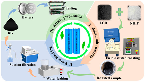
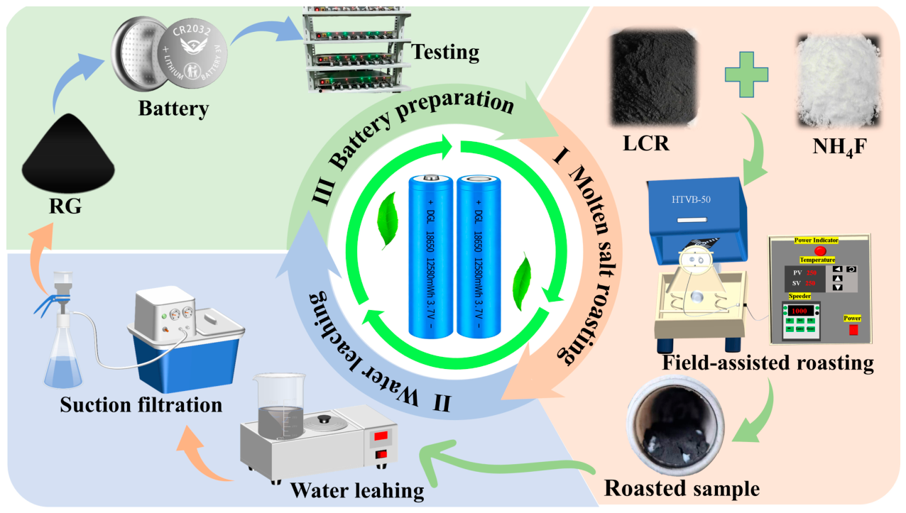
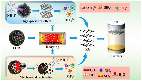
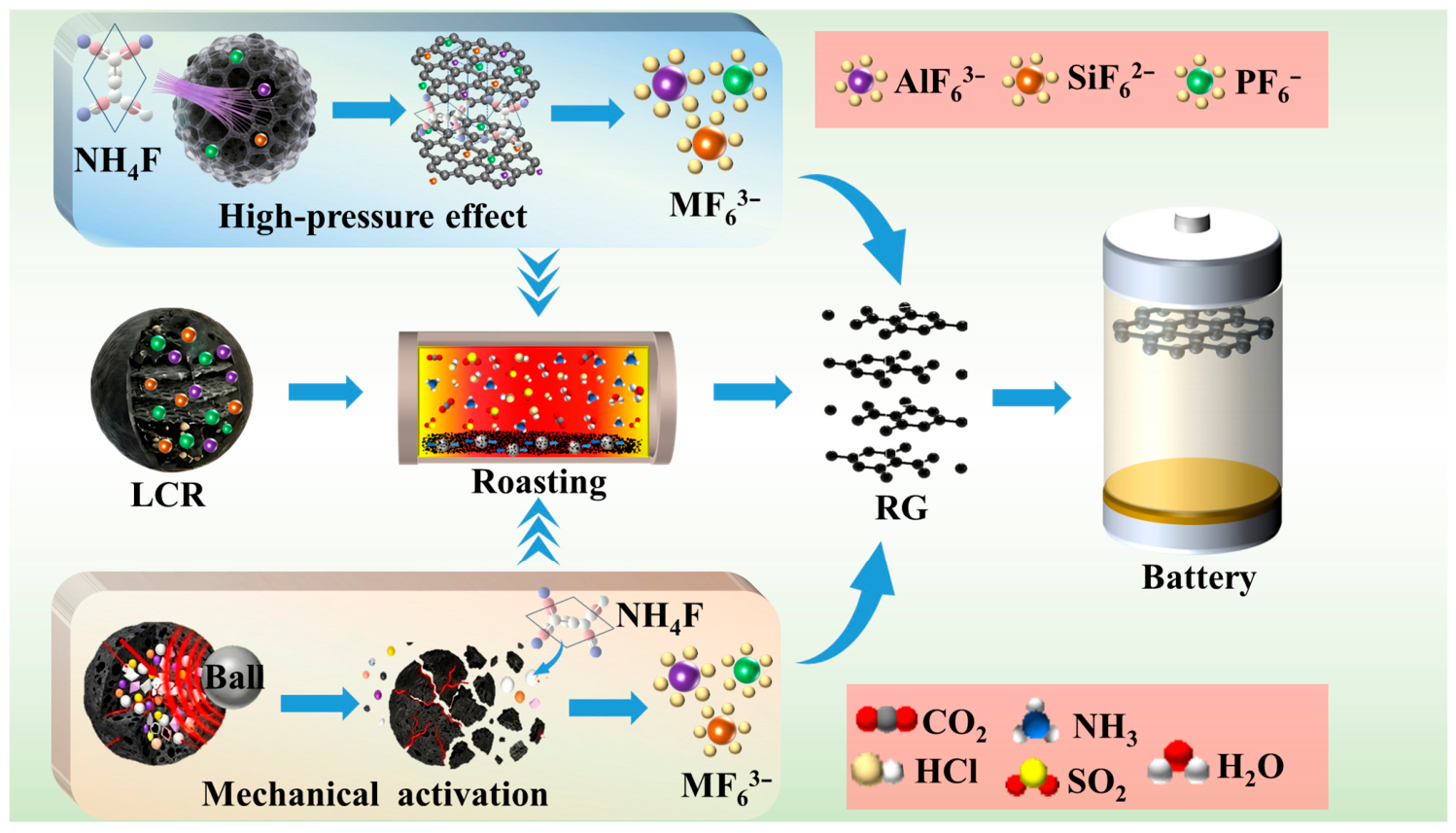
The LCR treatment process consisted of three main stages: external field-enhanced molten salt roasting, aqueous leaching, and electrode preparation and performance evaluation. A detailed schematic of the process is provided in Figure 1.
Figure 1.
Flowchart of LCR treatment using external field-assisted molten salt roasting.
2.2.1. External Field-Enhanced Ammonium Fluoride Molten Salt Roasting
The thoroughly dried LCR was uniformly mixed with NH4F at a predetermined mass ratio and placed in a sealed polytetrafluoroethylene reaction vessel. The mixture was subsequently subjected to molten salt roasting in a high-temperature vibration ball mill. The roasting parameters, including temperature (100–300 °C), salt-to-material ratio (0.25–1.25 g/g), roasting time (20–100 min), and vibration frequency (600–1400 r/min), were systematically optimized according to the experimental plan detailed in Table S1.
2.2.2. Water Leaching
Following roasting, the cooled sample was transferred to a polytetrafluoroethylene beaker and subjected to re-pulping water leaching (2–3 times) to remove soluble non-carbon impurities. The regenerated graphite (RG) was then recovered via solid–liquid separation, dried, and stored for subsequent characterization and testing. The aqueous leaching conditions, including temperature (20–80 °C), liquid-to-solid ratio (15–30 mL/g), and leaching time (30–120 min), were optimized following the protocol outlined in Table S2.
2.2.3. Electrode Preparation
The RG, carbon black (Super P), and PVDF binder were mixed in a mass ratio of 8:1:1. An appropriate amount of N-methyl-2-pyrrolidone (NMP) was added to dissolve the PVDF. After thorough grinding and homogenization, the resulting slurry was uniformly coated onto a 100 μm-thick copper foil and subsequently dried in a vacuum oven (Tianjin Test Instrument Technology Co., Ltd., Tianjin, China) at 80 °C for 12 h. The dried electrode sheets were cut into disks of 14 mm diameter, with an active material loading of approximately 2 mg/cm2. CR2032 coin-type half-cells were assembled in an argon-filled glovebox (Mikrouna Advanced Technology Co., Ltd., Shanghai, China) (H2O and O2 concentrations below 0.1 ppm). A lithium foil served as both the counter and reference electrode, and the electrolyte was 1 M LiPF6 dissolved in a mixture of ethylene carbonate, ethyl methyl carbonate, and dimethyl carbonate (EC:EMC:DMC = 1:1:1, v/v). A Celgard 2400 polypropylene membrane was used as the separator. The cells were assembled in the following sequence: negative electrode case, spring, spacer, lithium foil, electrolyte, separator, electrolyte, working electrode, and positive electrode case. Before electrochemical testing, the assembled cells were allowed to rest for 10 h to ensure electrolyte saturation.
2.3. Characterization
The phase composition of the samples was analyzed by X-ray diffraction (Ultima 4, Rigaku Corporation, Tokyo, Japan) using Cu Kα radiation, with data collected over a 2θ range of 10–80° at a scan rate of 10°/min. The microstructure and elemental distribution were examined using a scanning electron microscope (ZEISS SIGMA 300, Carl Zeiss, Oberkochen, Germany) equipped with an energy-dispersive X-ray spectrometer (Xplore 30, Oxford Instruments, Abingdon, UK). Raman spectroscopy (Invia Qontor, Renishaw, Wotton-under-Edge, UK) was employed to characterize the degree of graphitization. Surface properties were analyzed by nitrogen adsorption–desorption measurements using an automatic physical adsorption analyzer (TriStar II 3020, Micromeritics, Norcross, GA, USA). X-ray photoelectron spectroscopy (Thermo Scientific™, Waltham, MA, USA) was conducted to systematically characterize the surface elemental composition and chemical states of the regenerated graphite. The ash content of the regenerated graphite was determined according to the Chinese national standard for the proximate analysis of coal (GB/T 212-2008) [24].
2.4. Electrochemical Characterization
The electrochemical performance of the RG was evaluated using CR2032 coin-type half-cells (Saibo Electrochemical Materials Net, Beijing, China). Galvanostatic charge–discharge cycling was conducted within a voltage range of 0.005–2.0 V using a multichannel battery testing system (CT-4008Tn-5V1OmA-HWX, Neware Technology Co., Ltd., Shenzhen, China). Cyclic voltammetry (CV) and electrochemical impedance spectroscopy (EIS) were performed using an electrochemical workstation (CHI 760E, Chenhua Instrument Co., Ltd., Shanghai, China). CV curves were recorded at a scan rate of 0.1 mV/s over the voltage range of 0.005–2.0 V. EIS measurements were carried out over a frequency range of 0.01 Hz to 100 kHz with an AC amplitude of 5 mV.
3. Results and Discussion
3.1. Thermodynamic Analysis
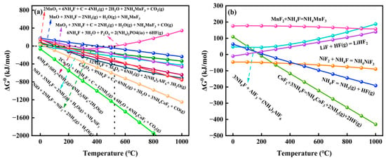
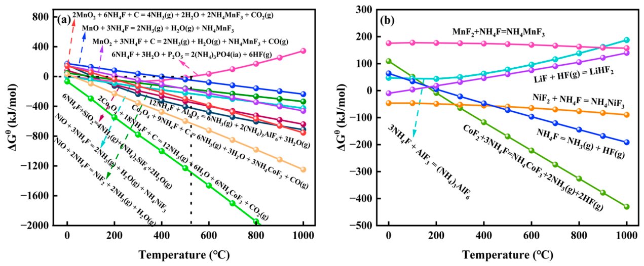
The potential chemical reactions occurring during the NH4F roasting process are summarized in Table 1, and the corresponding plots of the standard Gibbs free energy change as a function of temperature are presented in Figure 2.
Table 1.
Potential chemical reactions during the molten salt roasting process.
Figure 2.
relationship curves: (a) oxides; (b) fluorides.
The thermodynamic calculations presented in Table 1 and Figure 2 indicate that, within the molten salt system, NH4F initially reacts with metal oxides to form partially water-soluble ammonium complex salts and sparingly soluble fluorides. These fluorides can further react with HF to convert into acid-soluble complex salts. Specifically, the major compounds in LCR can undergo phase transformation in the NH4F system to form [AlF6]3−, [SiF6]2− and PO43− anions, which subsequently combine with [NH4]+ cations to yield highly water-soluble ammonium salts such as (NH4)3AlF6, (NH4)2SiF6, and (NH4)3PO4 [25,26]. As shown in Figure 2a, for the reactions between metal oxides and NH4F, the values for all reactions except (3-3) decrease with increasing temperature. At temperatures exceeding 300 °C, the values for the target reactions become negative, indicating that the oxides present in LCR can spontaneously undergo complexation and fluorination reactions with NH4F to form soluble ammonium salts containing anionic complexes such as [CoF3]−, [NiF3]−, [MnF3]−, [AlF3]3−, and [SiF3]2−. Furthermore, in the reactions (3-7), (3-8), (3-9), and (3-10), the carbonaceous matrix can serve as a reducing agent, facilitating the reduction in high-valence metal oxides to lower valence states before fluorination.
Figure 2b illustrates the thermodynamic behavior of the fluorides during the roasting process. At temperatures above 300 °C, the values for the reactions (3-13), (3-15), and (3-16) remain positive and show an increasing trend, indicating that elevated temperatures inhibit the spontaneous progress of these complexation reactions. In contrast, the values for the reactions (3-11), (3-12), and (3-14) remain negative, suggesting that these reactions proceed spontaneously. To prevent loss of the fluorinating agent due to NH4F decomposition and a consequent decrease in purification efficiency, the fluorination roasting temperature should be controlled within 200–300 °C. The thermodynamic analysis presented above confirms that NH4F molten salt roasting can effectively remove non-carbon impurities from LCR.
3.2. Optimization of Molten Salt Roasting and Leaching Parameters
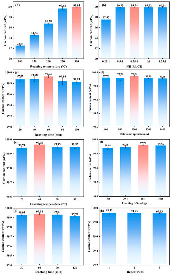
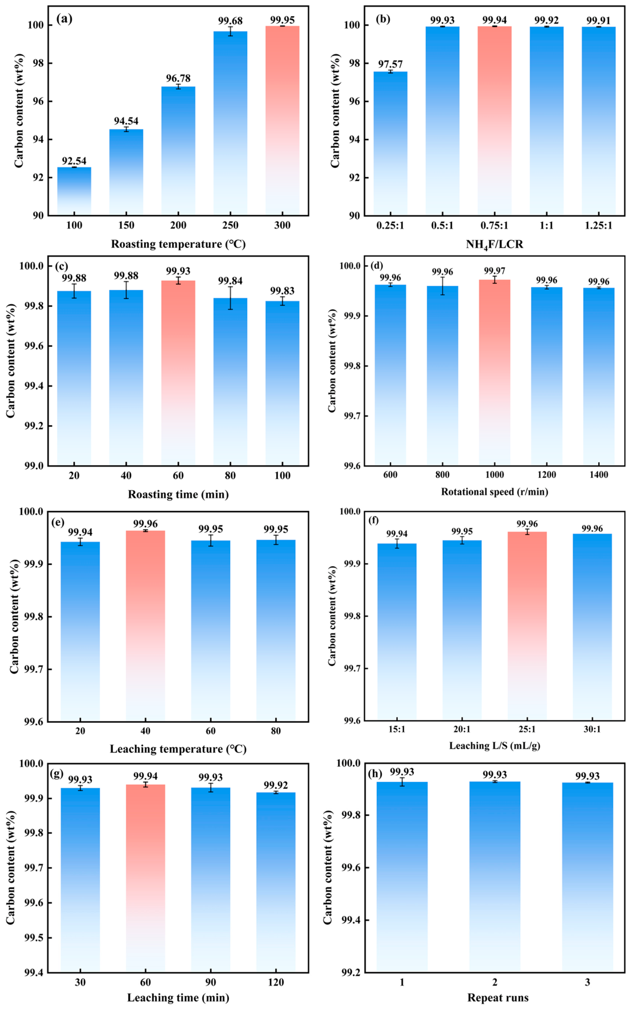
The effects of the key process parameters for molten salt roasting and aqueous leaching on the purity of the recovered graphite are illustrated in Figure 3. As depicted in Figure 3a, the roasting temperature significantly influences the carbon content of the RG. The carbon content increases with increasing roasting temperature, reaching a maximum of 99.95 wt% at 300 °C. This represents an increase of 13.96 wt% compared to the raw LCR (85.99 wt%). Consequently, 300 °C was selected as the optimal roasting temperature.
Figure 3.
Effect of process parameters in molten salt roasting and aqueous leaching on LCR purification efficiency: (a) roasting temperature, (b) salt-to-material ratio, (c) roasting time, (d) vibration frequency, (e) Leaching temperature, (f) liquid-to-solid ratio, (g) leaching time, and (h) process stability.
Figure 3b shows that, as the salt-to-material ratio increases, the carbon content of the RG initially increases, then decreases. The highest carbon content is observed at a salt-to-material ratio of 0.75:1. At higher ratios (1:1 and 1.25:1), the carbon content decreases. This is likely due to the increased proportion of the molten phase at high NH4F loadings, which enhances the encapsulation of fine carbon particles [27] and their subsequent removal during the aqueous leaching step. Therefore, a salt-to-material ratio of 0.75:1 was selected as optimal.
As illustrated in Figure 3c, the carbon content of the RG initially increases and then decreases with extended roasting time. A maximum carbon content of 99.93 wt% is achieved after 60 min of roasting, significantly higher than that obtained with shorter or longer roasting times. This trend can be attributed to the fact that an appropriate roasting time increases the proportion of the molten phase, promoting its penetration and diffusion into the pores of the carbon residue and providing sufficient kinetic conditions for the reactions, thereby enhancing the removal of impurities [28]. Therefore, a roasting time of 60 min was selected.
Figure 3d shows that, within the vibration frequency range of 600–1400 r/min, the carbon content of the RG remains consistently above 99.95 wt%, exhibiting only minor variations. The maximum carbon content of 99.98 wt% is observed at a vibration frequency of 1000 r/min. This frequency was therefore selected as optimal.
As shown in Figure 3e, the carbon content of the RG does not vary significantly with changes in the leaching temperature. A maximum value of 99.96 wt% is attained at a leaching temperature of 40 °C. Thus, 40 °C was selected as the optimal leaching temperature.
Figure 3f indicates that the carbon content initially increases with increasing liquid-to-solid ratio, reaching a maximum of 99.96 wt% at a ratio of 25:1, beyond which it stabilizes. A liquid-to-solid ratio of 25:1 was therefore selected as optimal.
As presented in Figure 3g, the carbon content of the RG exhibits only slight variations with changes in leaching time. The maximum carbon content of 99.94 wt% is observed at 60 min of leaching time. Prolonging the leaching time beyond this point results in a slight decrease in carbon content. Therefore, a leaching time of 60 min was selected as optimal.
The reproducibility of the process was assessed through three independent repeated experiments under the optimized conditions. As shown in Figure 3h, the RG carbon content remained consistently around 99.93 wt%, confirming the good reproducibility and stability of the developed process.
Taking into account both the carbon content of the RG and processing costs, the optimal combination of parameters for the molten salt roasting and aqueous leaching process was determined as follows: roasting temperature of 300 °C, salt-to-material ratio of 0.75:1, roasting time of 60 min, vibration frequency of 1000 r/min, leaching temperature of 40 °C, liquid-to-solid ratio of 25:1, and leaching time of 60 min. Under these optimized conditions, the carbon content of the RG obtained across three replicate experiments was consistently 99.93 wt% (Figure 3h).
3.3. Comparison of Physicochemical Properties of LCR, RG, and CG
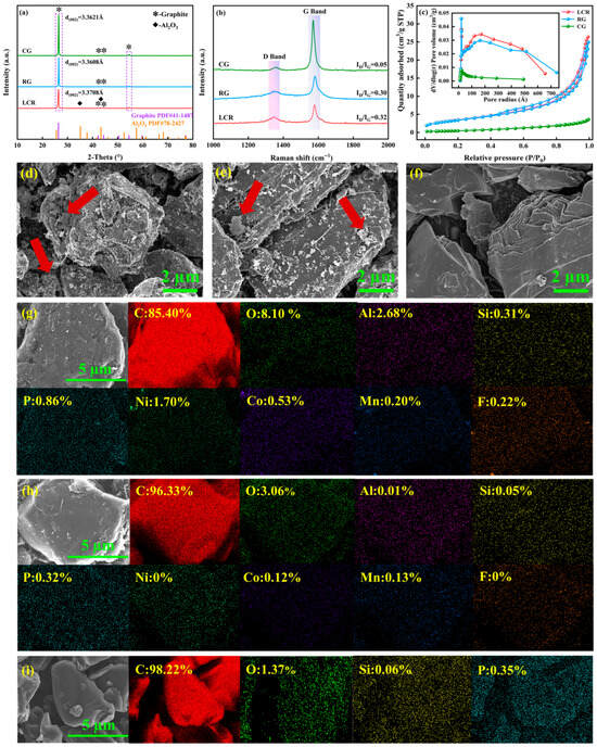
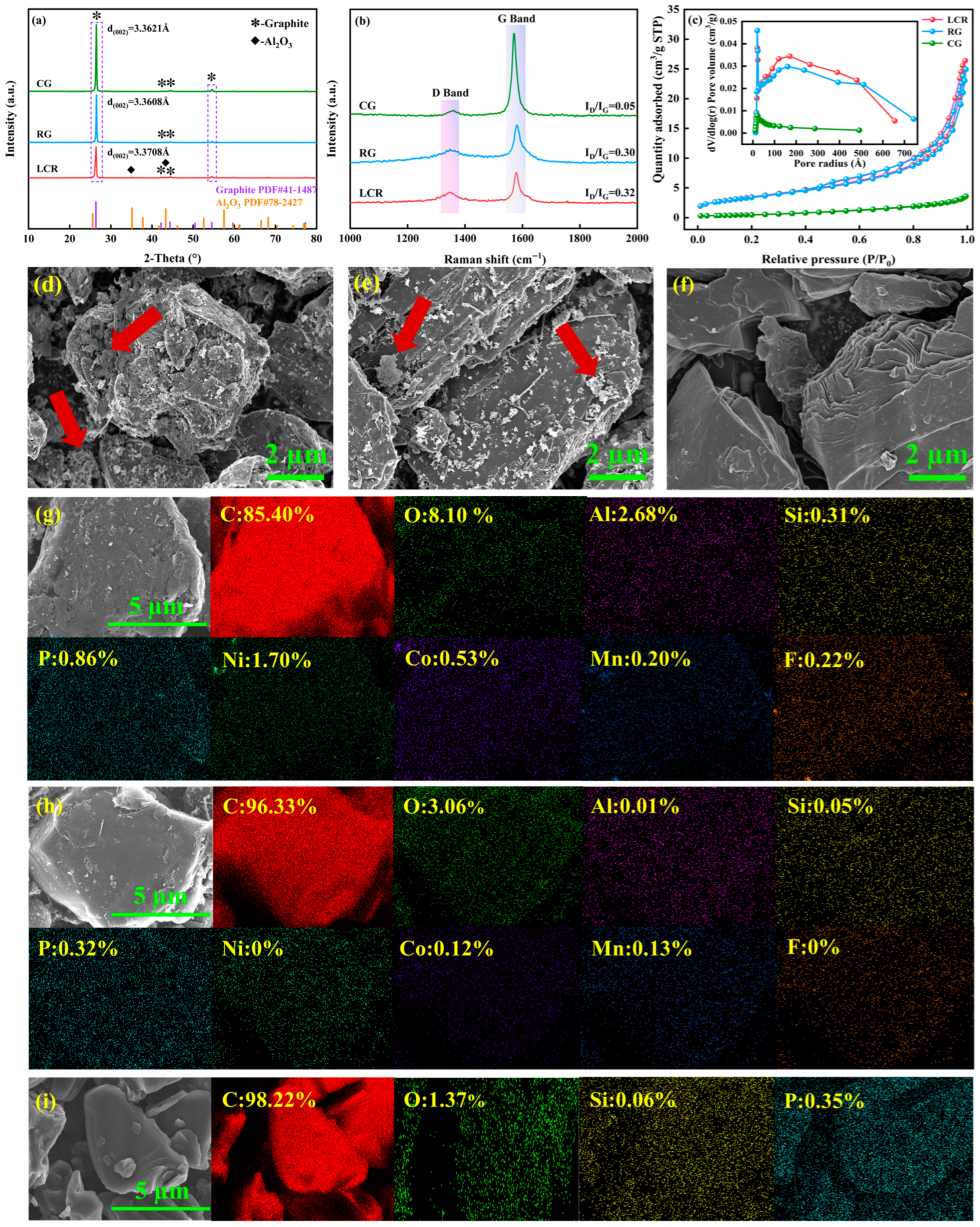
To evaluate the efficacy of the proposed process in restoring the structure and properties of the recovered graphite and to assess its potential for commercial applications, a comprehensive comparative analysis of the physicochemical properties of LCR, RG, and CG was performed. The properties investigated included crystal structure, degree of graphitization, microstructure, specific surface area, and elemental composition. The results are presented in Figure 4.
Figure 4.
Comparative analysis of the physicochemical properties of LCR, RG, and CG: (a) phase composition, (b) degree of graphitization, (c) pore structure and specific surface area, (d) microstructure of LCR, (e) microstructure of RG, (f) microstructure of CG, (g) elemental distribution of LCR, (h) elemental distribution of RG, and (i) elemental distribution of CG.
As shown in Figure 4a, all three samples (LCR, RG, and CG) exhibit distinct diffraction peaks characteristic of graphite, corresponding to the (002) crystal plane. Despite the prolonged service life of the graphite in the battery and the subsequent molten salt roasting process, LCR and RG retain a typical graphite crystal structure. A comparison of the (002) diffraction peak intensities reveals that RG exhibits a significantly higher peak intensity than LCR, indicating an increase in crystallinity following the combined roasting and leaching process. Moreover, an Al2O3 impurity peak is clearly observed in the LCR pattern, which is absent in the RG pattern. The interlayer spacings, d(002), were calculated to be 3.3708 Å, 3.3608 Å, and 3.3621 Å for LCR, RG, and CG, respectively. These results indicate that the proposed recovery process effectively removes residual impurities from LCR, achieving a carbon purity of 99.94 wt% (Figure 3g), and repairs the expanded graphite structure, thereby meeting the application requirements for battery anode materials.
Figure 4b displays the Raman spectra of LCR, RG, and CG. All samples exhibit two distinct characteristic peaks in the 1000–2000 cm−1 region: the D band at approximately 1350 cm−1, associated with structural defects, and the G band at approximately 1580 cm−1, corresponding to the in-plane vibration of sp2-hybridized carbon atoms. The ID/IG values for LCR, RG, and CG are 0.32, 0.30, and 0.05, respectively, indicating that RG still possesses a relatively high density of structural defects. This is attributed to the selective etching of graphite edges and defect sites by NH4F during the roasting process, which introduces additional defects and limits further graphitization.
The nitrogen adsorption–desorption isotherms for LCR, RG, and CG are shown in Figure 4c. All three samples exhibit Type IV isotherms with a hysteresis loop at low relative pressures and a sharp increase in adsorption at high relative pressures (P/P0 > 0.8), indicating a primarily mesoporous structure [29]. The specific surface areas (BET) of LCR, RG, and CG are 12.20 m2/g, 12.32 m2/g, and 1.87 m2/g, respectively. The corresponding pore volumes are 0.40 cm3/g, 0.37 cm3/g, and 0.01 cm3/g, and the average pore diameters are 60.03 Å, 57.33 Å, and 57.78 Å. These results suggest that impurity removal and subsequent restructuring of the pore network during the process result in a slight decrease in both pore volume and pore size.
As shown in Figure 4d–f, LCR particles exhibit a rough surface with numerous irregular white agglomerates corresponding to non-carbon impurities, along with fragmented edges. In contrast, the RG particles display a significantly cleaner surface with well-defined particle contours and a typical layered graphite structure. CG particles, on the other hand, exhibit a smooth and even surface with an intact layered structure. The EDS elemental mapping results (Figure 4g–i) show that LCR contains significant amounts of impurity elements, including O, Al, Ni, Co, and Mn. Following treatment, the concentrations of these non-carbon impurities in RG are substantially reduced, with the carbon content increasing to 96.33 wt%, approaching that of CG (98.22 wt%). These results corroborate the high efficiency of the proposed process in removing impurities and are consistent with the thermodynamic predictions (Figure 2). Overall, RG is comparable to CG in terms of phase composition, crystal structure, and elemental composition, although differences in graphitization degree and structural integrity are evident.
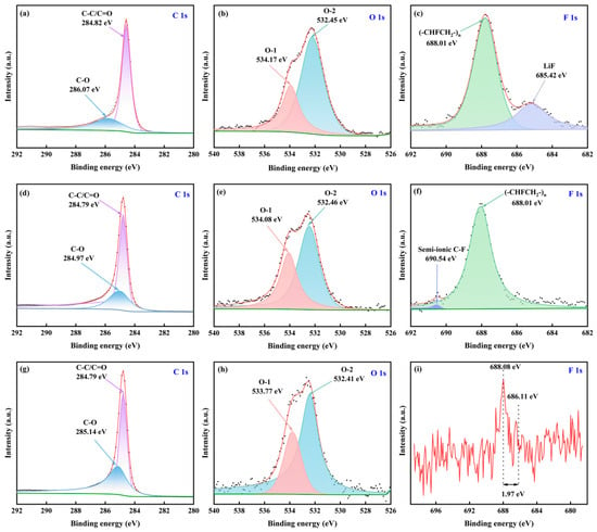
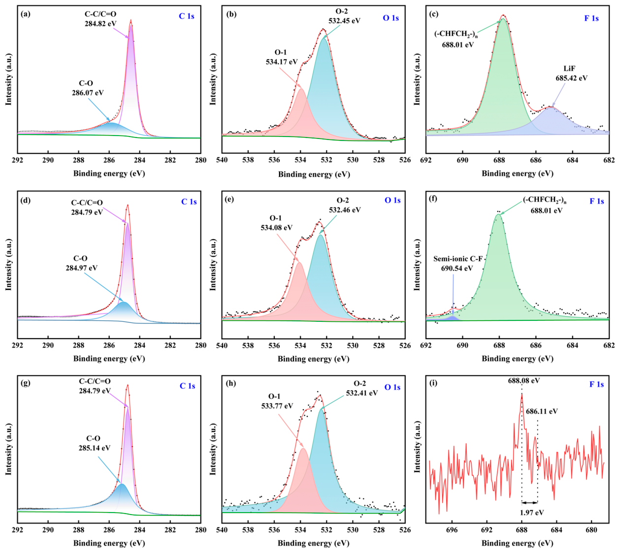
The XPS analysis results for LCR, RG, and CG are presented in Figure 5. The high-resolution C 1s spectra (Figure 5a,d,g) can be deconvoluted into two peaks corresponding to C-C/C=O (284.79–284.82 eV) [30] and C-O (285.14–286.07 eV) [31]. For LCR, the C-O peak exhibits the highest binding energy (286.07 eV) and a relatively high intensity, indicating the presence of abundant oxygen-containing functional groups and residual solid electrolyte interphase layers on the surface [32,33,34]. In the RG spectrum, the C-O peak binding energy decreases to 284.97 eV, and its intensity is substantially reduced, suggesting effective removal of these oxygen-containing species. CG exhibits the lowest binding energy (285.14 eV) for the C-O peak, with the weakest intensity. The C 1s spectral feature of RG closely resembles that of CG, indicating effective surface purification.
Figure 5.
XPS spectra: (a–c) LCR (C 1s, O 1s, F 1s), (d–f) RG (C 1s, O 1s, F 1s), and (g–i) CG (C 1s, O 1s, F 1s).
The O 1s spectra (Figure 5b,e,h) show that surface oxygen is primarily present in the form of oxygen-containing functional groups, which can be categorized as O-1 (C-O-C, C-OH) and O-2 (C=O, O-C-O) [35]. For LCR, the intensities of the O-1 (533.77–534.17 eV) and O-2 (532.41–532.46 eV) peaks are comparable, indicating a high abundance and diversity of oxygen species. In the RG spectrum, the O-1 peak intensity is significantly reduced, while the relative contribution of the O-2 peak increases. This suggests that the recovery process preferentially removes high-binding-energy oxygen-containing impurities, consistent with the thermodynamic analysis (Figure 2) and EDS results (Figure 4g). CG exhibits significantly lower intensities for both O-1 peaks compared to LCR and RG, with a higher proportion of the O-2 peak, indicating that the surface oxygen functionalities are primarily hydroxyl groups and are present in very low concentrations.
The F 1s spectra (Figure 5c,f,i) provide insights into the fluorine-containing species on the sample surfaces. LCR exhibits a peak at 688.01 eV, attributed to the (-CHFCH2-)ₙ groups in the PVDF binder [36], and a peak at 685.42 eV, assigned to LiF resulting from SEI decomposition [37]. This indicates the presence of residual electrolyte decomposition products and binder on the LCR surface. Following the treatment, the LiF peak completely disappears in the RG spectrum, while the (-CHFCH2-)n peak remains, and a new peak appears at 690.54 eV, which is attributed to semi-ionic C-F bonds [38]. This suggests that the process effectively removes LiF impurities while introducing a small number of stable C-F bonds. CG exhibits only weak signals at 686.11 eV and 688.08 eV, indicating a clean surface. Overall, the XPS results demonstrate that the surface impurity content of RG is significantly reduced to below the allowable limit for lithium-ion battery applications and that its surface chemical state is restored to one closely resembling that of CG, except for the residual C-F bonds. This provides a favorable surface chemical foundation for the recovery of its electrochemical performance.
3.4. Electrochemical Performance of Regenerated Graphite
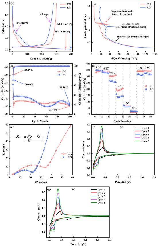
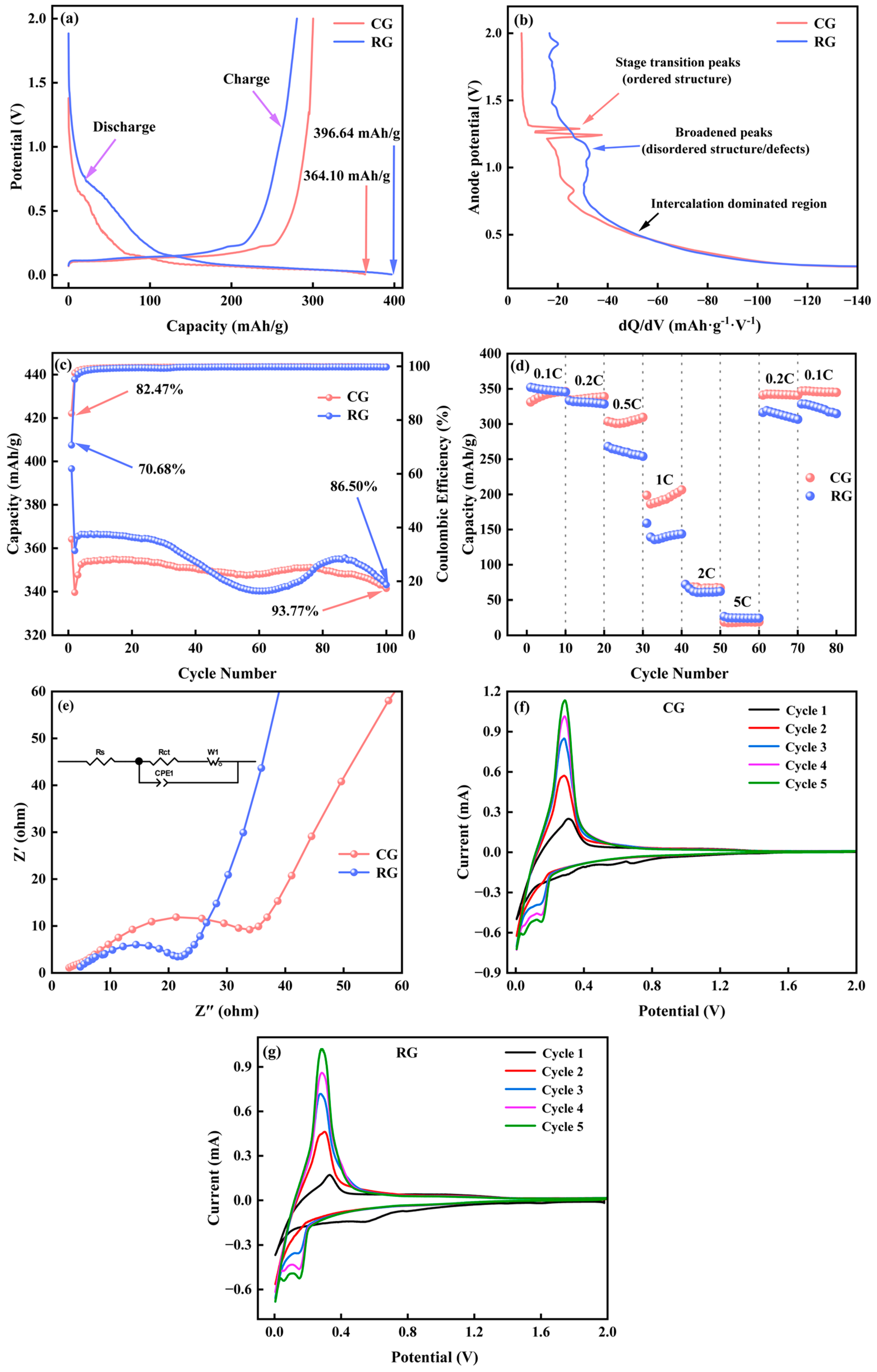
To assess the practical application potential of RG, its electrochemical performance was systematically compared with that of CG (Figure 6). As shown in Figure 6a, the initial discharge specific capacity of RG is 396.64 mAh/g, which is significantly higher than that of CG (364.10 mAh/g). However, the initial coulombic efficiency of RG (70.68%) is 11.79% lower than that of CG (82.47%). This disparity can be attributed to the morphological evolution of LCR from a rough, impurity-rich surface to a clean layered structure, while RG still retains a higher defect density (ID/IG = 0.30) and a larger specific surface area (12.32 m2/g), leading to irreversible lithium consumption [39]. These are the side reactions that need to be overcome, including electrolyte decomposition at defect sites and reaction of oxygen-containing functional groups with Li+. Meanwhile, the Stage-2 lithiation transition of RG is shorter than that of CG and the representative literature reports [40]. The dQ/dV analysis (Figure 6b) shows that the Stage-2 feature of RG is significantly weaker than that of CG. This is because structural defects arising from a lower graphitization degree disrupt the long-range ordering required for the formation of staged lithium-intercalated compounds, thereby shortening the Stage-2 voltage plateau. This conclusion was fully consistent with the Raman analysis result (ID/IG = 0.30, Figure 4b). Figure 6c shows the cycling performance of RG and CG at a current density of 0.1 C. After 100 cycles, RG retains 86.50% of its initial discharge capacity, while CG retains 93.77%. Although the coulombic efficiency of RG gradually increases with cycling and approaches that of CG, its cycling stability remains inferior. The relatively high specific surface area of RG (12.32 m2/g) introduces additional surface defects and active sites, which can exacerbate side reactions with the electrolyte and contribute to capacity fade [41].
Figure 6.
Electrochemical performance evaluation of RG and CG: (a) initial galvanostatic charge–discharge curves at 0.1 C; (b) differential capacity with respect to anode potential curve; (c) cycling stability at 0.1 C; (d) rate performance; (e) Nyquist plots; (f) CV curves of CG at a scan rate of 0.1 mV/s; (g) CV curves of RG at a scan rate of 0.1 mV/s.
The rate performance of RG and CG was evaluated at various current densities ranging from 0.1 C to 5 C, as shown in Figure 6d. The discharge specific capacity of RG is slightly lower than that of CG across all tested rates. Notably, the capacity of RG is close to its original value when the current density is returned to 0.1 C, demonstrating excellent rate reversibility. The EIS spectra for RG and CG are presented in Figure 6e. The charge transfer resistance (Rct) for RG is 22.56 Ω, which is lower than that of CG (39.6 Ω). The higher Rct for CG can be attributed to its highly ordered surface structure and fewer defects, resulting in fewer active sites for Li+ intercalation at the interface. Conversely, the presence of an optimal amount of structural defects in RG (ID/IG = 0.30) appears to facilitate electrolyte wetting and promote rapid Li+ migration [42]. Despite the lower charge transfer resistance of RG, its inferior rate capability arises from the higher defect density (ID/IG = 0.30) and larger specific surface area (12.32 m2/g), which trap Li+ and promote side reactions, hindering fast solid-state Li+ diffusion and increasing polarization at high current densities. The CV curves of CG and RG recorded at a scan rate of 0.1 mV/s are shown in Figure 6f,g, respectively. Both materials exhibit similar cathodic and anodic peaks, corresponding to the reversible intercalation and deintercalation of Li+ into/from the graphite structure. The comparable peak shapes and current responses indicate that the electrochemical reaction kinetics of RG are similar to those of CG. In summary, RG exhibits electrochemical performance closely resembling that of CG. It demonstrates favorable reversible capacity, cycling stability, rate capability, and electrochemical reversibility, highlighting its potential as a promising anode material for lithium-ion batteries.
3.5. Safe Disposal and Recycling Strategy for LCR
The safe disposal and recycling strategy of LCR are illustrated in Figure 7. LCR is characterized by a complex matrix in which commercial-grade graphite is intimately intergrown with aluminum silicate minerals and valuable metal compounds [43]. Conventional chemical leaching or high-temperature treatment methods often result in low-purity regenerated graphite, high energy consumption, elevated costs, and limited environmental benefits, rendering them unsuitable for large-scale applications. To overcome these limitations, this study proposes an innovative strategy for LCR treatment that integrates mechanical activation, a high-pressure environment, and low-temperature molten salt roasting.
Figure 7.
Schematic diagram of safe conversion and high-value utilization mechanisms of LCR.
First, leveraging the difference in reactivity between the graphite phase and the non-carbon impurity phases in LCR, mechanical activation is employed to fracture particles and enhance interfacial mass transfer. Simultaneous high-pressure application suppresses the decomposition and volatilization of the fluorinating agent (NH4F), thereby further improving mass transfer efficiency within the reaction system. This integrated approach enables the selective fluorination and conversion of impurity phases under low-temperature molten salt conditions, transforming insoluble components (aluminum and silicon compounds) into soluble MF63−-type complexes that can be readily removed during subsequent aqueous leaching. As shown in Figure 3, under optimized conditions, the carbon content of RG increases significantly from 85.99 wt% to 99.94 wt%.
Second, as demonstrated in Figure 4 and Figure 5, RG retains the characteristic layered crystal structure of graphite, albeit with a restructured pore network leading to a slight reduction in pore volume and pore size. The degree of graphitization is enhanced, and the carbon content of RG increases to 96.33 wt%, approaching that of CG (98.22 wt%). Non-carbon impurities, including oxygen-containing functional groups and SEI residues such as LiF, are effectively removed, resulting in a purified surface chemical state. The RG particles exhibit a significantly reduced surface impurity content, well-defined contours, and a restored layered structure, similar to those of CG.
Finally, as shown in Figure 6, RG demonstrates electrochemical performance comparable to CG when used as an anode material in LIBs. Specifically, RG delivers an initial discharge specific capacity of 396.64 mAh/g, outperforming CG (364.10 mAh/g), and exhibits an initial coulombic efficiency of 70.68%. After 100 cycles at 0.1 C, RG maintains a capacity retention of 86.50%. It also exhibits excellent rate reversibility, a low charge-transfer resistance (22.56 Ω), and CV profiles similar to those of CG, indicating comparable lithium intercalation/deintercalation behavior and reaction kinetics.
In summary, this study demonstrates the conversion of LCR into high-purity RG via a low-temperature molten salt roasting process synergistically enhanced by mechanical activation and a high-pressure environment. This approach aligns with circular economy principles by enabling closed-loop recycling of LCR, converting hazardous solid waste into a valuable commercial-grade graphite. A preliminary techno-economic assessment shows that the recycling cost of this process is 0.746 $/kWh [44], which is approximately 87% lower than that of commercial battery-grade artificial graphite 5.6 $/kWh [10]. This cost advantage, attributed to low-temperature operation and recyclable molten salt, supports its promising industrial application potential.
4. Conclusions
In this work, a process integrating high-pressure conditions and mechanical activation to support low-temperature molten salt roasting was proposed for the treatment of LCR. Thermodynamic analysis indicates that the fluorination reactions between NH4F and the non-carbon impurities (including aluminum silicates, valuable metal compounds, and fluorine-containing species) in LCR are thermodynamically spontaneous under low-temperature conditions (<300 °C). Under optimal process parameter conditions, the carbon content of the recovered RG reaches 99.94 wt%, and the process exhibits excellent reproducibility. The use of a high-pressure, sealed environment prevents the loss of HF (a decomposition product of NH4F), thereby creating a high-pressure gas–solid reaction system that promotes the conversion of non-carbon impurities into soluble fluorides. Simultaneously, mechanical activation enhances contact between the reaction medium and non-carbon impurities, facilitating their effective separation from the graphite matrix.
Furthermore, the low-temperature molten salt roasting process preserves the typical graphite crystal structure and intrinsic properties. Surface impurities (including oxygen-containing functional groups, LiF, and PVDF) are significantly removed, the pore structure is refined, and the surface chemical state of RG is restored to one closely resembling that of CG. Electrochemical evaluation shows that RG delivers an initial discharge specific capacity of 396.64 mAh/g at 0.1 C, with an initial coulombic efficiency of 70.68%, and maintains 86.50% capacity retention after 100 cycles. These results demonstrate its good lithium-ion storage and transport capabilities, with overall electrochemical performance comparable to that of CG. However, the cycling stability of RG remains inferior, and future work will focus on further repairing its crystal structure to optimize its electrochemical performance.
In conclusion, the proposed technology enables the efficient, environmentally friendly, and cost-effective recovery of graphite from LCR. Grounded in the principles of clean production and the circular economy, the recovered RG can be successfully reused as an anode material for LIBs, offering significant environmental and economic benefits. This approach is thus of great importance for promoting the full and sustainable utilization of spent lithium-ion batteries.
Supplementary Materials
The following supporting information can be downloaded at: https://www.mdpi.com/article/10.3390/min16040429/s1, Table S1: Experimental scheme for optimization of external field-enhanced auxiliary ammonium fluoride molten salt roasting parameters; Table S2: Experimental scheme for optimization of water leaching parameters.
Author Contributions
Y.Z.: Conceptualization; Formal Analysis; Writing—Original Draft. W.L.: Formal Analysis; Validation; Investigation. Y.L.: Methodology; Investigation. Z.Z.: Investigation. J.Z.: Investigation. Z.Y.: Writing—Review and Editing; Supervision. Q.Z.: Software; Investigation. F.W.: Resources; Writing—Review and Editing. All authors have read and agreed to the published version of the manuscript.
Funding
This work was supported by National Natural Science Foundation of China (52464055), China Postdoctoral Science Foundation (2024M760673), Guizhou Provincial Science and Technology Projects (NO. [2026]029, NO. [2023] General212, NO. [2023] General103, NO. LH [2024]Major028, and KJZY [2025]001), and Guizhou Provincial Department of Education Science and Technology Projects (NO. [2023]057).
Data Availability Statement
The data presented in this study are available on request from the corresponding author.
Conflicts of Interest
The authors declare that they have no known competing financial interests or personal relationships that could have appeared to influence the work reported in this paper.
References
- Wang, H.; Huang, Y.; Huang, C.; Wang, X.; Wang, K.; Chen, H.; Liu, S.; Wu, Y.; Xu, K.; Li, W. Reclaiming Graphite from Spent Lithium Ion Batteries Ecologically and Economically. Electrochim. Acta 2019, 313, 423–431. [Google Scholar] [CrossRef] [Scilit]
- Rey, I.; Vallejo, C.; Santiago, G.; Iturrondobeitia, M.; Lizundia, E. Environmental Impacts of Graphite Recycling from Spent Lithium-Ion Batteries Based on Life Cycle Assessment. ACS Sustain. Chem. Eng. 2021, 9, 14488–14501. [Google Scholar] [CrossRef] [Scilit]
- Wang, L.; Wang, C.; Zhang, J.-Y.; Qiu, J.-C.; Fu, X.-W.; Zhang, Z.-R.; Feng, J.-M.; Dong, L.; Long, C.-L.; Li, D.-J.; et al. Graphite Recycling from Spent Lithium-Ion Batteries for Fabrication of High-Performance Aluminum-Ion Batteries. Rare Met. 2024, 43, 2161–2171. [Google Scholar] [CrossRef] [Scilit]
- Shahjalal, M.; Roy, P.K.; Shams, T.; Fly, A.; Chowdhury, J.I.; Ahmed, M.R.; Liu, K. A Review on Second-Life of Li-Ion Batteries: Prospects, Challenges, and Issues. Energy 2022, 241, 122881. [Google Scholar] [CrossRef] [Scilit]
- Zheng, M.; You, Y.; Lu, J. Understanding Materials Failure Mechanisms for the Optimization of Lithium-Ion Battery Recycling. Nat. Rev. Mater. 2025, 10, 355–368. [Google Scholar] [CrossRef] [Scilit]
- Zou, J.; Zhang, R.; Zhang, Y.; Chen, L.; Huang, Y.; Sun, X. Extraction of Organic Solvents and Preferential Recovery of Lithium from Spent Lithium-Ion Batteries by in-Situ Carbothermal Reduction. Process Saf. Environ. Prot. 2024, 187, 259–269. [Google Scholar] [CrossRef] [Scilit]
- Zhu, X.; Xiao, J.; Mao, Q.; Zhang, Z.; Tang, L.; Zhong, Q. Recycling of Waste Carbon Residue from Spent Lithium-Ion Batteries via Constant-Pressure Acid Leaching. Trans. Nonferrous Met. Soc. China 2022, 32, 1691–1704. [Google Scholar] [CrossRef] [Scilit]
- Lv, X.; Sun, X.; Bu, W.; Tan, X.; Zhu, J.; Han, Z. An Efficient Recycling Process of Spent Cathode Carbon Blocks via Low Temperature Molten Salt Roasting and Two Stage Leaching. Sep. Purif. Technol. 2025, 361, 131566. [Google Scholar] [CrossRef] [Scilit]
- Shojaei, M.; Guelfo, J.L.; Barlaz, M.A.; Cogollo-Carcamo, G.; Rivera, N.A.; Hsu-Kim, H.; Ferguson, P.L. Evaluation of Fluorochemical Leaching from Lithium-Ion Batteries Under Simulated Solid Waste Landfill Conditions. Environ. Sci. Technol. 2025, 59, 26750–26761. [Google Scholar] [CrossRef] [Scilit]
- Rantala, V.; Kauppinen, T.; Välikangas, J.; Hu, T.; Lähde, A.; Tuomikoski, S.; Lassi, U. Comparison of Thermal and Chemical Purification Methods for Graphite from Spent Lithium-Ion Batteries. Sep. Purif. Technol. 2025, 376, 133992. [Google Scholar] [CrossRef] [Scilit]
- Liang, J.; Chen, R.; Gu, J.; Li, J.; Xue, Y.; Shi, F.; Huang, B.; Guo, M.; Jia, J.; Li, K.; et al. Sustainable Recycling of Spent Ternary Lithium-Ion Batteries via an Environmentally Friendly Process: Selective Recovery of Lithium and Non-Hazardous Upcycling of Residue. Chem. Eng. J. 2024, 481, 148516. [Google Scholar] [CrossRef] [Scilit]
- Rabeeh, G.; Fariborz, F.; Brian, J.; Cristina, P.-G.; Chakraborty, B.P. Current Challenges and Future Opportunities toward Recycling of Spent Lithium-Ion Batteries. Renew. Sustain. Energy Rev. 2022, 159, 112202. [Google Scholar] [CrossRef] [Scilit]
- Zhu, X.; Chen, Y.; Xiao, J.; Xu, F.; Su, F.; Yao, Z.; Zhang, Z.; Tang, L.; Zhong, Q. The Strategy for Comprehensive Recovery and Utilization of the Graphite Anode Materials from the End-of-Life Lithium-Ion Batteries: Urgent Status and Policies. J. Energy Storage 2023, 68, 107798. [Google Scholar] [CrossRef] [Scilit]
- Zhang, Z.; Zhu, X.; Hou, H.; Tang, L.; Xiao, J.; Zhong, Q. Regeneration and Utilization of Graphite from the Spent Lithium-Ion Batteries by Modified Low-Temperature Sulfuric Acid Roasting. Waste Manag. 2022, 150, 30–38. [Google Scholar] [CrossRef] [Scilit]
- Ma, X.; Chen, M.; Chen, B.; Meng, Z.; Wang, Y. High-Performance Graphite Recovered from Spent Lithium-Ion Batteries. ACS Sustain. Chem. Eng. 2019, 7, 19732–19738. [Google Scholar] [CrossRef] [Scilit]
- Yu, J.; He, Y.; Ge, Z.; Li, H.; Xie, W.; Wang, S. A Promising Physical Method for Recovery of LiCoO 2 and Graphite from Spent Lithium-Ion Batteries: Grinding Flotation. Sep. Purif. Technol. 2018, 190, 45–52. [Google Scholar] [CrossRef] [Scilit]
- Gao, Y.; Zhang, J.; Jin, H.; Liang, G.; Ma, L.; Chen, Y.; Wang, C. Regenerating Spent Graphite from Scrapped Lithium-Ion Battery by High-Temperature Treatment. Carbon 2022, 189, 493–502. [Google Scholar] [CrossRef] [Scilit]
- GB/T 24533-2019; Graphite Negative Electrode Materials for Lithium Ion Battery. Standardization Administration of China: Beijing, China, 2019.
- Zhu, D.; Wang, H.; Pan, J.; Yang, C. Influence of Mechanical Activation on Acid Leaching Dephosphorization of High-Phosphorus Iron Ore Concentrates. J. Iron Steel Res. Int. 2016, 23, 661–668. [Google Scholar] [CrossRef] [Scilit]
- Tunç Parlak, T.; Yildiz, K. Investigation of the Effect of Mechanical Activation on Nickel and Cobalt Extraction from Laterite at Atmospheric Pressure by Kinetics and Leach Residue Analysis. Can. Metall. Q. 2025, 64, 680–697. [Google Scholar] [CrossRef] [Scilit]
- Wang, X.; Yu, H.; Zhou, J.; Wang, H. Upgrading Anode Graphite from Retired Lithium Ion Batteries via Solid-Phase Exfoliation by Mechanochemical Strategy. Waste Manag. 2024, 182, 102–112. [Google Scholar] [CrossRef] [Scilit]
- Song, D.; Zhang, B.; Du, H.; Wu, J.; Yu, J.; Li, J. Flash Recovery of Lithium from Spent Anode Graphite by Carbothermal Shock and Water Leaching. Green Chem. 2025, 27, 6595–6606. [Google Scholar] [CrossRef] [Scilit]
- Zhai, W.; Wu, X.; Qian, J.; Zuo, X.; Li, Y.; Gao, J.; Yuan, J.; Xia, Y. Subcritical Impurity Removal and Regeneration of Spent Graphite Anodes Achieving 99.5% Purity. Carbon 2025, 238, 120216. [Google Scholar] [CrossRef] [Scilit]
- GB/T 212-2008; Proximate Analysis of Coal. Standards Press of China: Beijing, China, 2008.
- Puzhel, A.O.; Borisov, V.A.; Osipov, A.R.; Petlin, I.V.; Kiselev, A.D.; Adeeva, L.N. Fluoride Processing of a Fluid Cracking Catalyst Resulting in the Recovery of a Rare-Earth-Element Concentrate. Russ. J. Non-Ferr. Met. 2021, 62, 174–178. [Google Scholar] [CrossRef] [Scilit]
- Siebeneichler, S.; Dorn, K.V.; Smetana, V.; Valldor, M.; Mudring, A.-V. A Soft Chemistry Approach to the Synthesis of Single Crystalline and Highly Pure (NH4)CoF3 for Optical and Magnetic Investigations. J. Chem. Phys. 2020, 153, 104501. [Google Scholar] [CrossRef] [Scilit]
- Zhang, S.; Zhang, S.; Li, J.; Li, J.; Zhou, X.; Wang, L.; Li, F.; Man, J.; Jia, X.; Yao, S. Carbon Deposition Mechanism of Molten Salt Cleaning and Optimization of Multicomponent Molten Salt Formula for Remanufacturing. Sci. Prog. 2021, 104, 00368504211031078. [Google Scholar] [CrossRef] [Scilit]
- Yang, K.; Gong, P.; Tian, Z.; Lai, Y.; Li, J. Recycling Spent Carbon Cathode by a Roasting Method and Its Application in Li-Ion Batteries Anodes. J. Clean. Prod. 2020, 261, 121090. [Google Scholar] [CrossRef] [Scilit]
- Wang, L.; Jiang, Y.; Li, S.-Y.; Chen, X.-H.; Xi, F.-S.; Wan, X.-H.; Ma, W.-H.; Deng, R. Scalable Synthesis of N-Doped Si/G@voids@C with Porous Structures for High-Performance Anode of Lithium-Ion Batteries. Rare Met. 2023, 42, 4091–4102. [Google Scholar] [CrossRef] [Scilit]
- Su, L.-X.; Lou, Q.; Jiao, Z.; Shan, C.-X. Plant Cell Imaging Based on Nanodiamonds with Excitation-Dependent Fluorescence. Nanoscale Res. Lett. 2016, 11, 425. [Google Scholar] [CrossRef] [Scilit]
- Biesinger, M.C.; Payne, B.P.; Grosvenor, A.P.; Lau, L.W.M.; Gerson, A.R.; Smart, R.S.C. Resolving Surface Chemical States in XPS Analysis of First Row Transition Metals, Oxides and Hydroxides: Cr, Mn, Fe, Co and Ni. Appl. Surf. Sci. 2011, 257, 2717–2730. [Google Scholar] [CrossRef] [Scilit]
- Dedryvère, R.; Laruelle, S.; Grugeon, S.; Gireaud, L.; Tarascon, J.-M.; Gonbeau, D. XPS Identification of the Organic and Inorganic Components of the Electrode/Electrolyte Interface Formed on a Metallic Cathode. J. Electrochem. Soc. 2005, 152, A689. [Google Scholar] [CrossRef] [Scilit]
- Verma, P.; Maire, P.; Novák, P. A Review of the Features and Analyses of the Solid Electrolyte Interphase in Li-Ion Batteries. Electrochim. Acta 2010, 55, 6332–6341. [Google Scholar] [CrossRef] [Scilit]
- Aurbach, D. Review of Selected Electrode–Solution Interactions Which Determine the Performance of Li and Li Ion Batteries. J. Power Sources 2000, 89, 206–218. [Google Scholar] [CrossRef] [Scilit]
- Lee, D.W.; De Los Santos, V.L.; Seo, J.W.; Felix, L.L.; Bustamante, D.A.; Cole, J.M.; Barnes, C.H.W. The Structure of Graphite Oxide: Investigation of Its Surface Chemical Groups. J. Phys. Chem. B 2010, 114, 5723–5728. [Google Scholar] [CrossRef] [Scilit]
- An, S.J.; Li, J.; Daniel, C.; Wood, D.L. Effects of Ultraviolet Light Treatment in Ambient Air on Lithium-Ion Battery Graphite and PVDF Binder. J. Electrochem. Soc. 2019, 166, A1121–A1126. [Google Scholar] [CrossRef] [Scilit]
- Gao, A.; Lai, H.; Duan, M.; Chen, S.; Huang, W.; Yang, M.; Gong, L.; Chen, J.; Xie, F.; Meng, H. LiF Artifacts in XPS Analysis of the SEI for Lithium Metal Batteries. ACS Appl. Mater. Interfaces 2025, 17, 8513–8525. [Google Scholar] [CrossRef] [Scilit]
- Yue, H.; Zhang, W.; Liu, H.; Liu, Z.; Zhong, G.; Yang, Y. Synthesis and Characterization of Fluorinated Carbon Nanotubes for Lithium Primary Batteries with High Power Density. Nanotechnology 2013, 24, 424003. [Google Scholar] [CrossRef] [Scilit]
- Lu, Y.; Zhang, Z.; Zhong, Q.; Yao, Z.; Wu, J.; Zhang, J.; Wang, L.; Xiao, J. Oxygen-Rich Modified-Graphite Recycled from Spent Lithium Batteries for Improved Lithium-Ion Storage: Adsorption and Intercalation Mechanisms. Sep. Purif. Technol. 2025, 359, 130798. [Google Scholar] [CrossRef] [Scilit]
- Shellikeri, A.; Watson, V.; Adams, D.; Kalu, E.E.; Read, J.A.; Jow, T.R.; Zheng, J.S.; Zheng, J.P. Investigation of Pre-Lithiation in Graphite and Hard-Carbon Anodes Using Different Lithium Source Structures. J. Electrochem. Soc. 2017, 164, A3914–A3924. [Google Scholar] [CrossRef] [Scilit]
- Cho, Y.; Lee, S.; Yang, S.; Jeong, S.-K. Regeneration of Spent Graphite from Lithium-Ion Batteries by Malic-Acid Leaching and Alkaline EDTA Chelation. Int. J. Mol. Sci. 2026, 27, 2322. [Google Scholar] [CrossRef] [Scilit]
- Li, J.; Zhou, H.; Gou, Y.; Zeng, Z.; Wang, B.; Sun, W.; Yang, Y.; Ge, P. Quenching of Spent Graphite: Upcycling Regeneration with Tailoring Subsurface and in-Plane Defects towards High-Rate Properties. J. Power Sources 2025, 641, 236890. [Google Scholar] [CrossRef] [Scilit]
- Vanderbruggen, A.; Gugala, E.; Blannin, R.; Bachmann, K.; Serna-Guerrero, R.; Rudolph, M. Automated Mineralogy as a Novel Approach for the Compositional and Textural Characterization of Spent Lithium-Ion Batteries. Miner. Eng. 2021, 169, 106924. [Google Scholar] [CrossRef] [Scilit]
- Xie, S.; Dong, Y.; Wang, X.; Zeng, Z.; Zhou, H.; Yuan, Z.; Sun, W.; Ji, X.; Yang, Y.; Ge, P. Tailored Anion Radii of Molten-Salts Systems toward Graphite Regeneration with Excellent Energy-Storage Properties. Energy Storage Mater. 2024, 70, 103510. [Google Scholar] [CrossRef] [Scilit]

Disclaimer/Publisher’s Note: The statements, opinions and data contained in all publications are solely those of the individual author(s) and contributor(s) and not of MDPI and/or the editor(s). MDPI and/or the editor(s) disclaim responsibility for any injury to people or property resulting from any ideas, methods, instructions or products referred to in the content. |
© 2026 by the authors. Licensee MDPI, Basel, Switzerland. This article is an open access article distributed under the terms and conditions of the Creative Commons Attribution (CC BY) license.