


Abstract
High-intensity conditioning (HIC) is a common pretreatment process for enhancing the flotation of fine-grained minerals. This study introduces fractal theory into the structural design of pulp conditioning impellers. A fractal blade with multi-scale fractal edge features was proposed, and its separation performance was evaluated in a fine-grained malachite (−20 μm) and quartz flotation system. Computational fluid dynamics simulation revealed that the fractal blade altered the energy dissipation pattern. Compared with conventional rectangular blades, it induced stronger fluid compression and collision effects in localized regions. These hydrodynamic changes improved the suspension homogeneity and dispersion efficiency of fine-grained malachite. Furthermore, the fractal blade reduced the scale of turbulent vortices while increasing local turbulent kinetic energy and shear rates. This optimized turbulent flow field effectively reduced mass-transfer resistance and promoted interfacial interactions between flotation reagents and mineral particles. Adsorption experiments and optical microscopy indicated that after conditioning at 1500 rpm for 3 min, the fractal blade increased sodium oleate adsorption on malachite compared to the conventional blade. This enhanced adsorption promoted the aggregation of fine-grained malachite, increasing its aggregate size by 15.52%, while no significant aggregation was observed for quartz particles. Consequently, the single mineral flotation recovery of fine-grained malachite increased by 4.13%. For artificial mixed minerals, the copper concentrate grade and recovery were improved by 2.28% and 1.04%, respectively. This study provides a theoretical basis for equipment optimization and structural innovation design in HIC processes.
1. Introduction
With the depletion of high-grade, easily beneficiated copper sulfide resources, the flotation recovery of oxidized copper ores has received increasing attention [1,2,3]. These oxidized ores are formed through the chemical weathering of primary minerals in surface oxidation-hydrolysis environments [4]. Due to long-term weathering and oxidation, the content of useful minerals existing in the ore in a fine granular or encapsulated state is high. Malachite (Cu2(OH)2CO3), a typical oxidized copper mineral, is intergrown with silicate gangue such as quartz [5]. The fine particles of these minerals possess large specific surface areas and high surface energies, which readily induce inter-particle hetero-coagulation and slime coating on the surfaces of valuable minerals [6]. Therefore, improving the separation of fine valuable minerals from fine gangue is a critical research direction for the effective utilization of oxidized copper resources.
High-intensity conditioning (HIC) is a key pretreatment step before flotation. It creates a highly turbulent environment to strip slime coatings, enhances interactions between mineral particles and collectors, and promotes flocculation, thereby improving the recovery of fine-grained minerals [7,8,9,10]. However, the practical effectiveness of HIC depends heavily on impeller geometry and operating conditions [11,12,13]. Parameters such as impeller number, pitch angle, diameter, width, and agitation speed determine the flow field distribution and the mixing efficiency. Li et al. [7] investigated the impact of impeller diameter and angle on the HIC of fine-grained pyrite. They found that increasing these parameters improved the velocity gradient and turbulent kinetic energy. This change subsequently enhanced the suspension of fine particles. In another study, Li et al. [14] optimized the agitation speed and time within a multi-bladed impeller system. This optimization improved the flow velocity distribution and wall shear stress near the impellers, thereby significantly increasing the effective collision probability between particles and reagents, and the adsorption rate of collectors on mineral surfaces. Although adjusting these parameters improves the overall flow field, conventional rectangular impellers still suffer from inherent hydrodynamic limitations. Fluid boundary layer separation readily occurs on the leeward side of these standard impellers [15]. This separation generates large-scale wake-shedding vortices [16]. These vortices increase fluid drag and energy consumption [17]. More importantly, they hinder the transfer of turbulent energy to small-scale eddies, resulting in insufficient local shear intensity to promote effective collisions between fine particles and reagents.
The design of novel impellers is an effective approach to improve the flow field distribution in stirred tanks. In recent years, novel impellers such as V-shaped [18], U-shaped [19], and fishtail-shaped [20] types, as well as rigid–flexible composite types [21], have been designed based on geometric principles. These designs effectively enhance fluid mixing performance. However, current research mainly focuses on the overall impeller parameters, while studies on specific blade designs remain limited. Optimizing the blade shape itself can effectively regulate local flow field distribution. For example, curving the leading face of the blades allows the fluid to flow more smoothly along the blade surface. It delays boundary-layer separation and suppresses the formation of macroscopic wake vortices [22]. Furthermore, fractal geometry, with its self-similar and multi-scale features, can further regulate the distribution of turbulent kinetic energy. Compared with conventional rectangular blades, applying fractal structural characteristics to the blade-edge designs is equivalent to building a multi-scale turbulence generator [23]. As the fluid passes through these fractal boundaries, it undergoes progressive shearing, which converts large-scale vortices into small-scale vortices comparable to fine particles, thereby intensifying local energy dissipation and shear forces [24].
This study focuses on the HIC system of fine-grained malachite (−20 μm) and quartz. Based on the optimal impeller configuration established in previous research [7], this study proposes a novel fractal blade structure. This structure combines curved flow-guiding surfaces with multi-scale edge features. Computational fluid dynamics (CFD) was used to evaluate the hydrodynamic properties and solid suspension characteristics of various blade designs. Subsequently, the study explored the interfacial chemical mechanisms. It examined how flow field optimization affects reagent adsorption, particle aggregation, and flotation separation behavior. This research aims to provide a theoretical basis and technical reference for the structural optimization of pulp conditioning equipment.
2. Materials and Methods
2.1. Materials
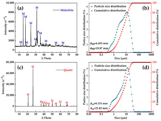
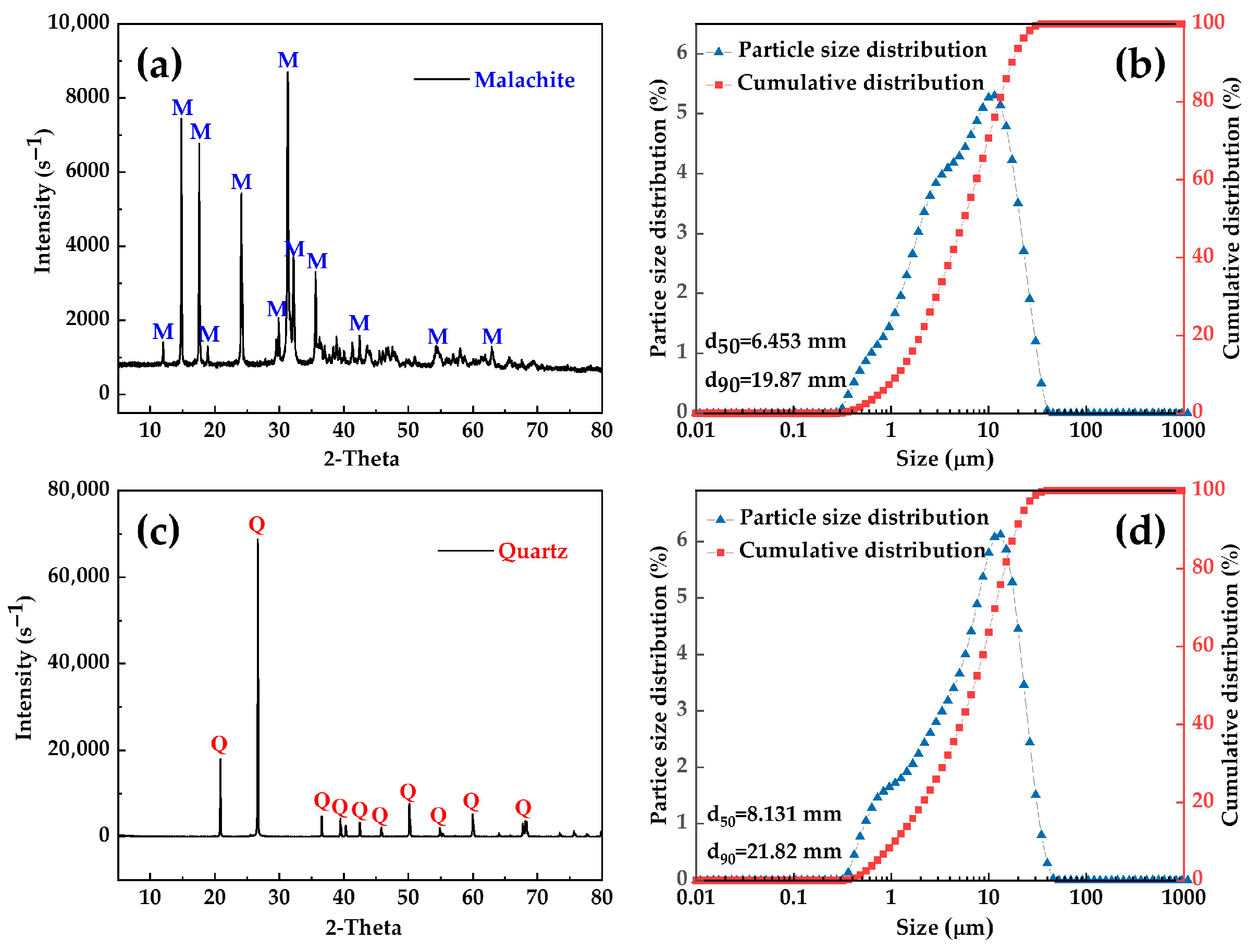
The malachite and quartz samples were obtained from Kunming, Yunnan Province, China. The raw minerals were crushed, ground, and sieved. Subsequently, the −20 μm size fraction was collected for all experiments. The results of X-ray diffraction, X-ray fluorescence, and laser particle size measurements are presented in Figure 1 and Table 1. Both samples exhibited minor impurity peaks and similar particle size distributions. These results indicate the high purity of the prepared minerals.
Figure 1.
(a) X-ray diffraction pattern and (b) particle size distribution of malachite; (c) X-ray diffraction pattern and (d) particle size distribution of quartz.
Table 1.
Chemical multi-element analysis results for malachite and quartz.
Analytical-grade NaOH and HCl from Sinopharm Chemical Reagent Co., Ltd., Shanghai, China were used as pH regulators. Analytical-grade sodium oleate (NaOL) and sodium silicate (Na2SiO3) from Macklin Biochemical Co., Ltd., Shanghai, China were used as the collector and depressant, respectively. Deionized water (DI) with a resistivity exceeding 18 MΩ·cm was used throughout the experiments.
2.2. Optimization Design of Blade Structure
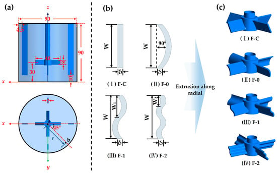
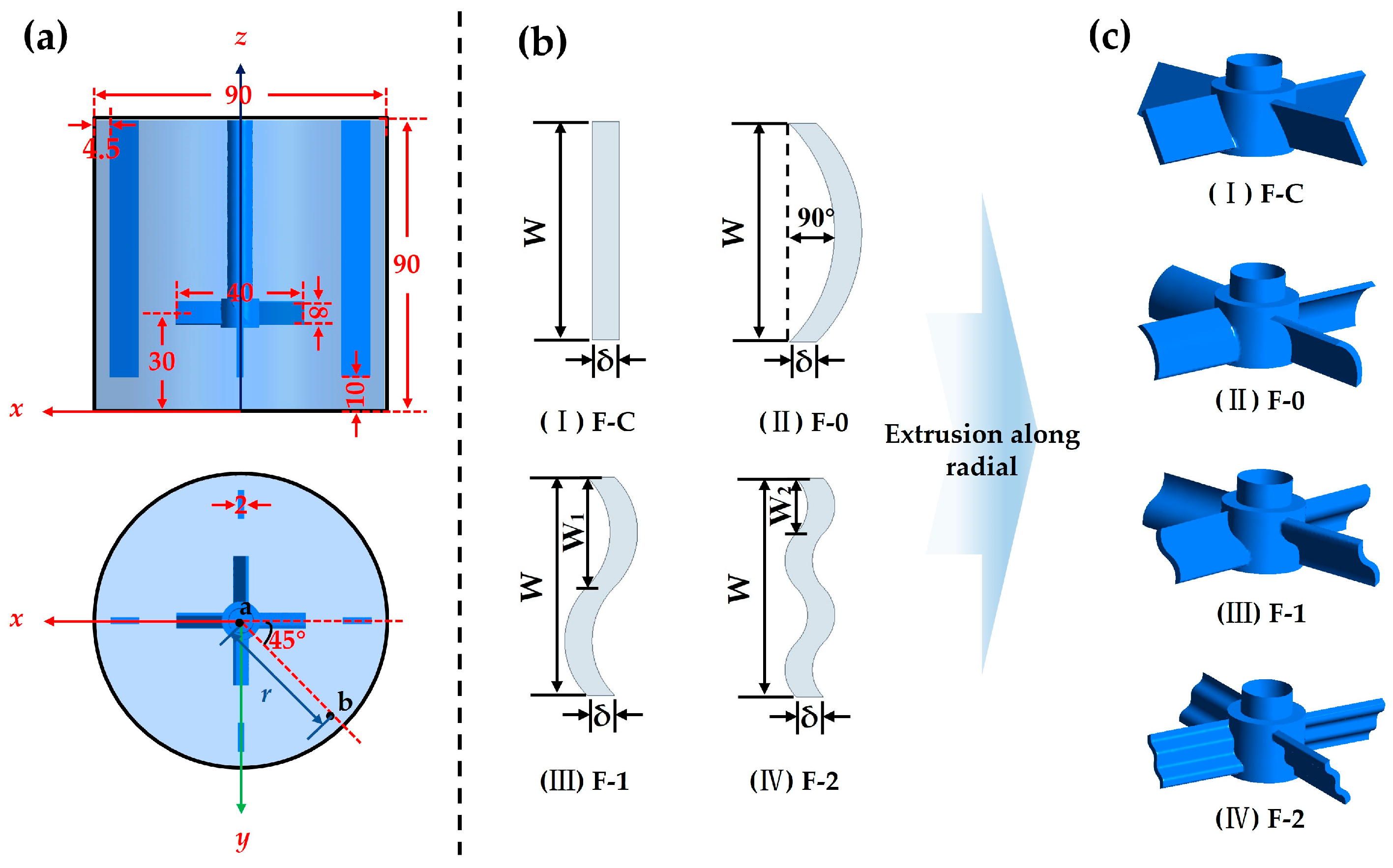
The geometric model and structural parameters of the stirred tank are presented in Figure 2a. In accordance with standard stirred tank design specifications, both the tank diameter (D) and height (H) were set to 90 mm. Additionally, four vertical baffles were symmetrically positioned within the tank. To ensure sufficient axial circulation, a four-blade axial flow impeller with a radius (R) of 20 mm and a pitch angle of 60° was used. Furthermore, the off-bottom clearance of the impeller was set to 1/3 of the tank height. This positioning was designed to minimize particle sedimentation at the bottom and maintain a stable macroscopic circulation throughout the tank.
Figure 2.
(a) Geometric model and structural parameters of the stirred tank (b is the maximum sampling point along the 45° radial direction from the impeller center; b = 2.12R); (b) schematic diagram of the iterative design of the fractal blade; (c) schematic diagram of the impeller structures (unit: mm).
This study presents a fractal-featured impeller blade structure, designed via iterative optimization based on fractal self-similarity and scale invariance. The design and three-dimensional modeling process of the fractal blades are illustrated in Figure 2b. The resulting blade structures were derived from the fractal iteration of the cross-sectional profile of a conventional rectangular blade (F-C). The initial cross-sectional profile corresponded to the F-C blade, with a width (W) of 8 mm and a thickness (δ) of 2 mm. By stretching the straight-line segment corresponding to the blade width into a 90° arc, the fundamental zero-order fractal iteration curve (F-0) was generated. Subsequently, the width of the single arc was reduced to half that of the F-0, while the stretching angle was maintained at 90°, forming the first-order fractal iteration curve (F-1) comprising two arcs. A further iteration, which again halved the arc width relative to the F-1, yielded the second-order iteration fractal curve (F-2) consisting of four arcs. Throughout the entire fractal iteration process, the geometric parameters of the curves strictly followed a fractal scaling relationship. This relationship is expressed as W2 = 1/2 W1 = 1/4 W.
During the transformation from two-dimensional profiles to three-dimensional solids, the aforementioned fractal iteration curves were defined as the cross-sections of the blades. These profiles were then linearly extruded along the radial direction of the impeller to generate individual three-dimensional fractal blades. Finally, the generated blades were symmetrically arrayed around the central hub to form the complete fractal impeller structures with fractal edge features described in this study, as illustrated in Figure 2c.
The longitudinal symmetry plane at y = 0 and the horizontal cross-section at z = 30 mm were selected as characteristic observation planes. To analyze the turbulent vortex dissipation scales and concentration variance, 100 sampling points were uniformly distributed along the axial height, along the 45° radial direction (line ab) at various radial distances r from the impeller center.
2.3. Numerical Simulation
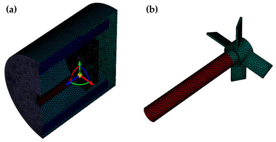
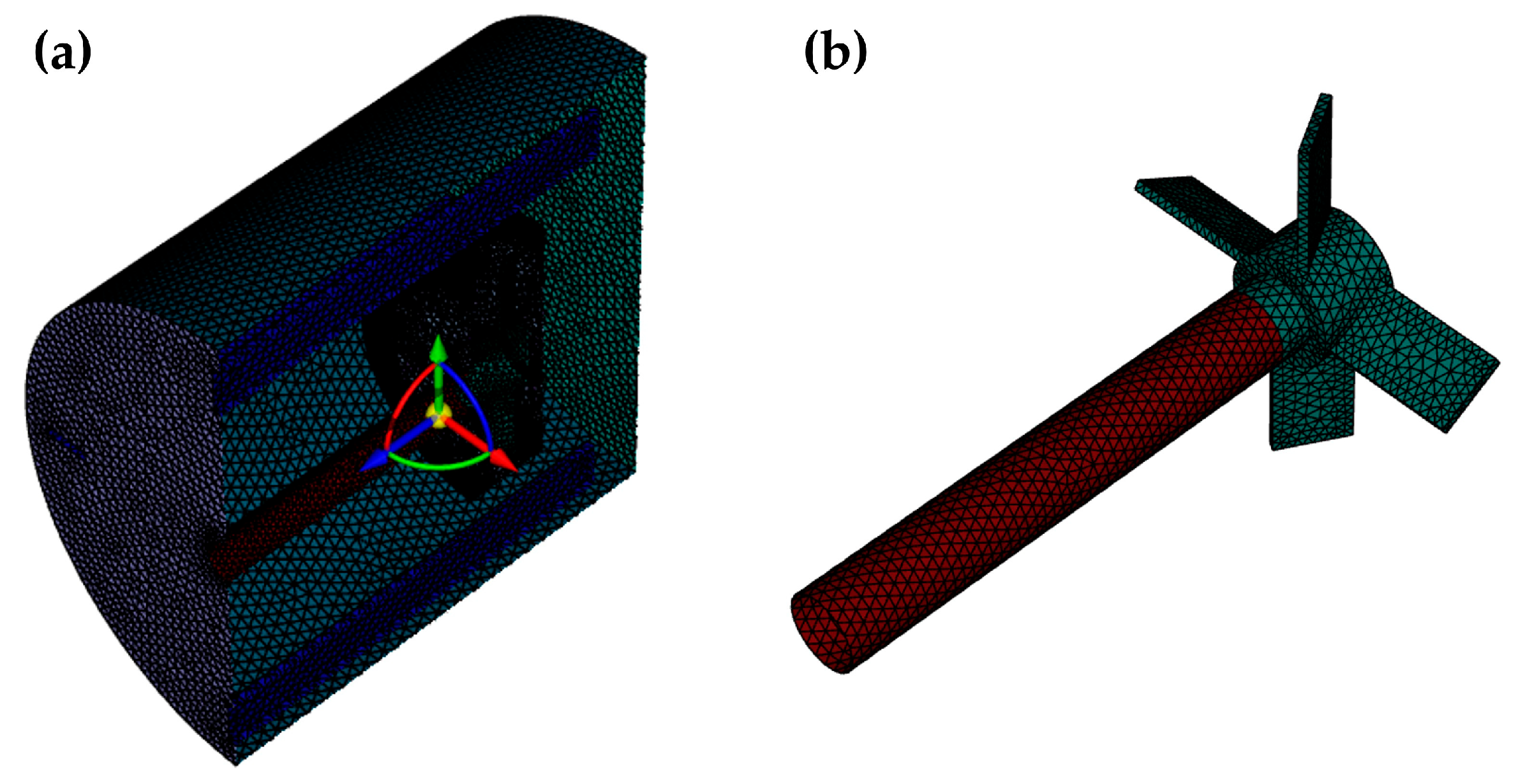
Computational fluid dynamics enables a comprehensive simulation and analysis of the flow field within stirred tanks. This approach reveals the inherent patterns and characteristics of fluid flow [18,25]. A three-dimensional model of the stirred tank was created based on the geometric parameters specified in Section 2.2. The Spaceclaim module within the commercial software ANSYS Fluent 2022 R1 was used to construct this geometry. Hexahedral unstructured meshes and tetrahedral structured meshes were applied to the impeller and tank regions, respectively. Additionally, volumetric meshing was used for local refinement. The final mesh schematics are illustrated in Figure 3.
Figure 3.
Schematic of the grid layout: (a) stirred tank; (b) stirred impeller.
The malachite particles were selected as the representative solid phase. These particles were treated as a pseudo-fluid, and the phase volume fraction was introduced to describe their volume proportion. The Euler–Euler multiphase model was employed to simulate the malachite-water two-phase flow in the stirred tank. A solid volume fraction of 2.13%, corresponding to the pulp density of 9.68% used in the experiments, was set as the standard for achieving a completely uniform suspension of malachite particles in the stirred tank. The standard k-ε model was selected for turbulence calculation [26].
The malachite density was set to 4000 kg/m3 with a particle size of 20 μm. The water density and dynamic viscosity were specified as 998 kg/m3 and 0.00103 Pa·s, respectively. The agitation speed was maintained at 1500 rpm. The Multiple Reference Frame (MRF) method was applied to simulate impeller rotation. For the boundary conditions, the free liquid surface was defined as a symmetry boundary. The interface between the stationary and rotating domains was specified as an interior boundary. All remaining surfaces were assigned as wall boundaries. The Gidaspow drag model was used to calculate the interphase drag force between water and malachite particles [27]. A pressure–velocity coupling scheme was employed for the solution process. To enhance solution convergence, a second-order upwind scheme was applied to discretize the turbulent kinetic energy, momentum, and time. Finally, the simulation time step was set to 0.005 s, with 2000 time steps and a maximum of 50 iterations per step, resulting in a total simulated time of 10 s.
2.4. Pulp Conditioning and Flotation Tests
High-intensity conditioning effectively enhances interfacial interactions between reagents and mineral particles, promoting the formation of hydrophobic mineral aggregates and thereby improving flotation recovery [7,9,28]. In this study, the conditioning experiments were conducted using a stirring apparatus constructed from acrylic glass. During the pulp conditioning process, 15 g of the pure mineral sample and 140 mL of DI water were added to the stirred tank, resulting in a pulp density of 9.68 wt%. The pulp was then agitated for 1 min to ensure complete dispersion of the mineral. Subsequently, the pulp pH was adjusted to 8 using NaOH or HCl, followed by an additional 2 min of agitation. Finally, NaOL was added, and the agitation speed was maintained at 1500 rpm for 3 min.
After pulp conditioning, single mineral and artificially mixed mineral flotation tests were performed separately. The flotation experiments were conducted using an XFG-II flotation machine manufactured by Prospecting Machinery Factory, Changchun, China.
During the single mineral flotation stage, the impeller speed was set to 1992 rpm to ensure sufficient gas dispersion. Although this speed exceeds the pulp conditioning speed of 1500 rpm, it does not disrupt the pre-formed aggregates. Due to significant differences in geometric dimensions, impeller diameters, and stator-rotor configurations between the stirred tank and the flotation machine, the high rotational speed in the flotation cell primarily drives macroscopic gas-liquid mixing. In contrast, the HIC process primarily relies on shear forces to promote the formation of hydrophobic aggregates [29]. Furthermore, these aggregates induced by the HIC process exhibit a highly dense structure and floc strength [30], enabling them to withstand macroscopic turbulence during flotation and maintain stable separation indices. After 6 min of flotation, the concentrates and tailings were dried and weighed. Finally, the flotation recovery was calculated based on these weights.
In the artificially mixed mineral tests, fine-grained malachite and quartz were uniformly mixed at a 1:1 ratio. For each test, 15 g of the mixed sample was added to the stirred tank. NaOL and Na2SiO3 were then added sequentially for pulp conditioning and flotation. The resulting concentrates and tailings were collected and subsequently analyzed by X-ray diffraction to measure their copper grades. To minimize experimental error, each experiment was repeated three times. The average values were used for the final recovery calculation. The copper recovery was calculated according to Equation (1):
where XCu is the copper recovery, %; β1 and β2 are the copper grades in the concentrate and tailings, respectively, %; M1 and M2 are the masses of the concentrate and tailings, respectively, g.
2.5. Adsorption Testing
The samples were prepared according to the pulp conditioning procedure described in Section 2.4. The residual concentration method was employed to determine the adsorption of NaOL on the malachite and quartz surfaces [31]. After centrifugation to separate the solid phase, the supernatant was appropriately diluted. To ensure the rigor of the analysis, a full-spectrum scan (190–400 nm) was initially performed on a NaOL standard solution using a UV–Vis spectrophotometer (UV-2600, Shimadzu Corporation, Kyoto, Japan) to determine its characteristic maximum absorption wavelength. Subsequently, the absorbance of all test samples was quantitatively measured at this determined wavelength. The adsorption amount of NaOL on the mineral surfaces was calculated according to Equation 2:
In the equation, Qe (mg/g) represents the amount of reagent adsorbed onto the mineral surface; C0 and Ce (mg/L) represent the initial concentration and test concentration, respectively; V (mL) represents the volume of the solution; and m (g) represents the mass of the sample.
2.6. Optical Microscope Observation
The size and shape of particle aggregates can be directly observed using an optical microscope [13]. The samples were prepared according to the pulp conditioning procedure described in Section 2.4. An optical microscope (CX33, Olympus, Tokyo, Japan) was then used to observe the aggregation of malachite and quartz particles. From the uniformly mixed pulp, an aliquot was extracted from random locations within the stirred tank using a pipette and subsequently diluted. A 1 mL diluted pulp was then deposited onto a glass slide, carefully spread to ensure the aggregates formed a single layer to the greatest extent possible. The samples were examined under a microscope at 100× magnification. To ensure sample representativeness and data accuracy, ten independent samplings and observations were conducted for each experimental condition. Subsequently, the particle size distribution was statistically analyzed using ImageJ 1.53t software.
3. Results
3.1. Analysis of Flow Field Characteristics
3.1.1. Fluid Velocity Distribution
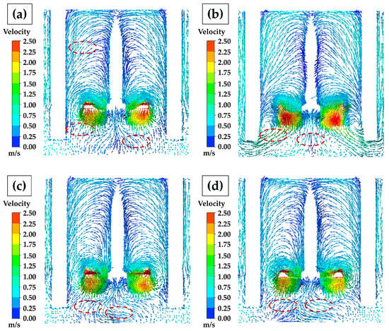
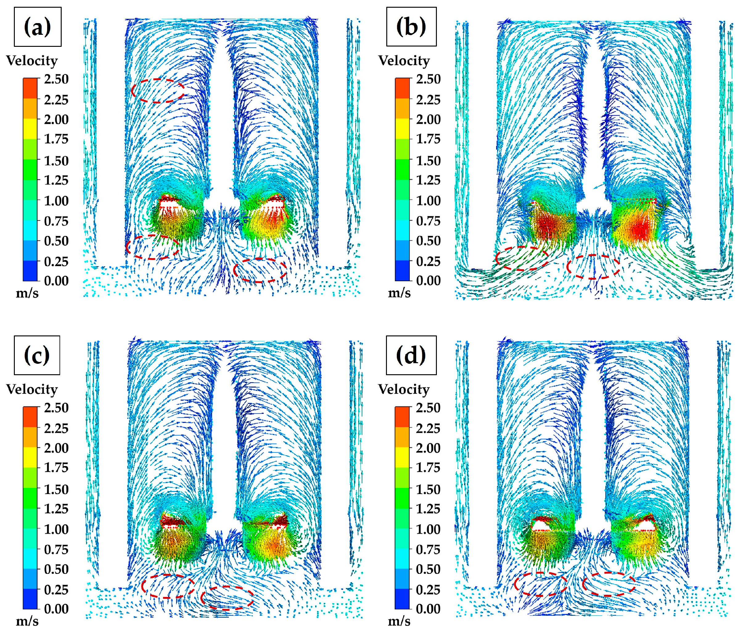
Figure 4 illustrates the macroscopic flow field characteristics under different blade structures. All four blade structures generated a typical axial circulation pattern within the stirred tank. The high-velocity zones were primarily concentrated at the blade tips and the radial discharge side. A comparison of the local flow fields revealed that the blade shape significantly influenced the distribution of flow field at the tank bottom. As shown by the red-dashed area in the figure, a distinct weak mixing zone was observed at the bottom of the F-C tank. The application of the F-0 blade increased the fluid discharge angle, thereby reducing the weak mixing zone at the tank bottom and increasing the fluid velocity in the upper and middle sections. Compared to the F-0, the F-1 blade induced distinct convective collision trajectories in the bottom region, resulting in a stronger fluid compression effect. Subsequently, the F-2 blade amplified this effect, forming the most intense localized flow zone around the impeller, as illustrated in Figure 4d.
Figure 4.
The velocity vector distribution of four blade structures: (a) F-C; (b) F-0; (c) F-1; (d) F-2.
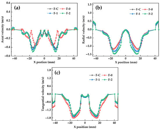
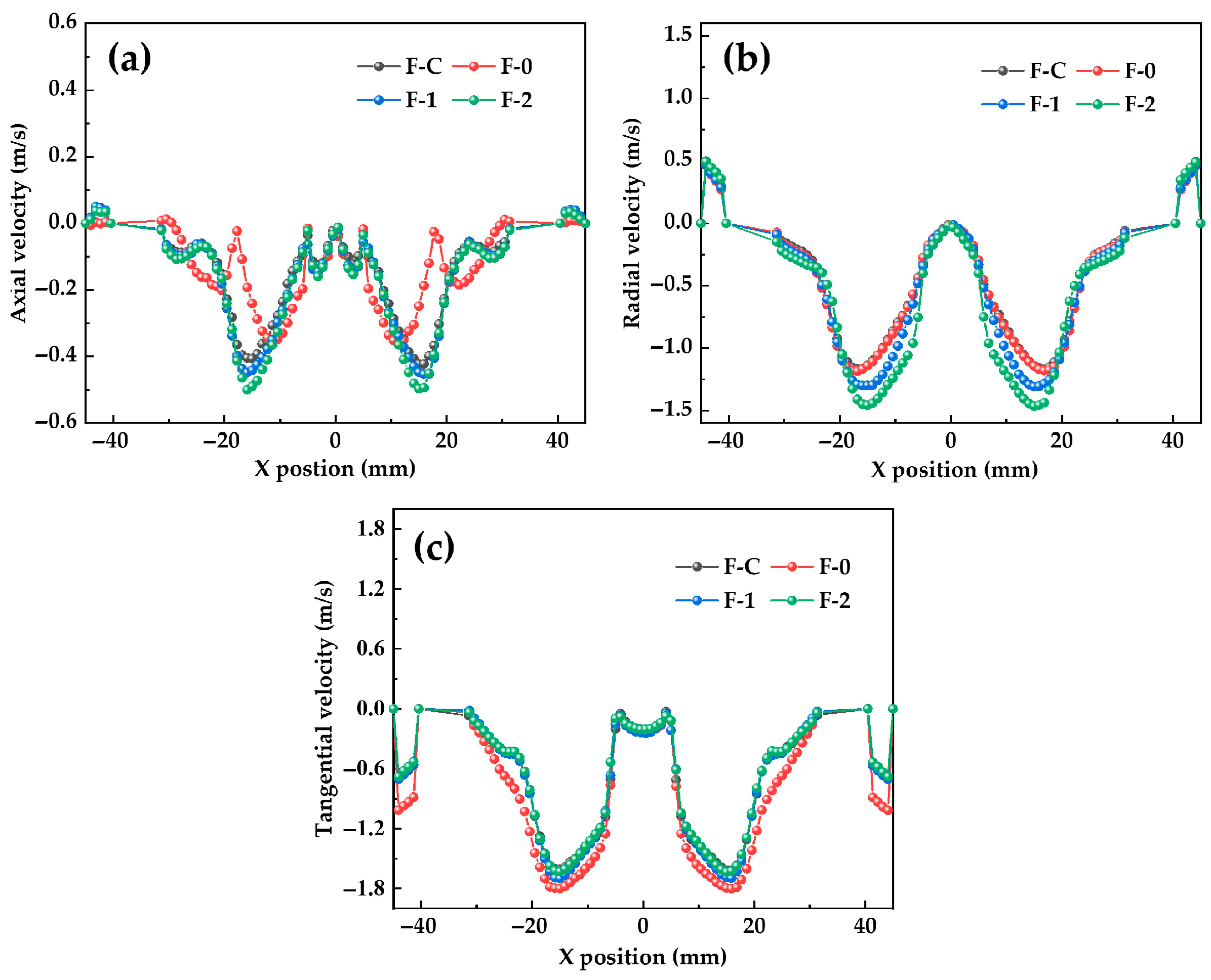
Figure 5 further illustrates the spatial distribution of the axial, radial, and tangential fluid velocities at z = 30 mm for four blade configurations. The positive directions for these velocities are defined as upward, radially outward from the axis toward the tank wall, and counterclockwise, respectively. As shown in Figure 5a,b, the maximum axial and radial velocities consistently occurred at x = ±15 mm. With increasing fractal iterations, these two velocity components showed a clear upward trend. Specifically, compared to the conventional F-C blade, the maximum axial velocities for the F-1 and F-2 structures increased from 0.41 m/s to 0.44 m/s and 0.49 m/s, respectively. Similarly, the maximum radial velocities were enhanced from 1.17 m/s to 1.30 m/s and 1.46 m/s, respectively. Conversely, the tangential velocity distribution demonstrated a different evolutionary pattern. The F-0 blade exhibited the highest peak value of 1.8 m/s at x = ±15 mm. However, compared to the F-0 blade, the peak tangential velocities for the F-1 and F-2 configurations decreased by 0.11 m/s and 0.17 m/s, respectively.
Figure 5.
The velocity distribution of four blade structures: (a) axial; (b) radial; (c) tangential.
As noted by Huang et al., the axial velocity determines the suspension state of particles in the tank, while the radial velocity controls the dispersion and transfer of particles and reagents [32]. Compared to a conventional rectangular blade, the complex geometric structure of the fractal blades alters the distribution of velocity. Specifically, it reduces the tangential flow intensity of the impeller region while simultaneously enhancing the axial and radial flow intensities. This conversion of velocity components strengthens fluid transport toward the tank bottom and walls, thereby providing more favorable hydrodynamic conditions for particle suspension and reagent dispersion.
3.1.2. Turbulent Kinetic Energy and Kolmogorov Scale Distribution
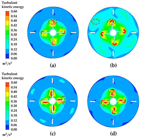
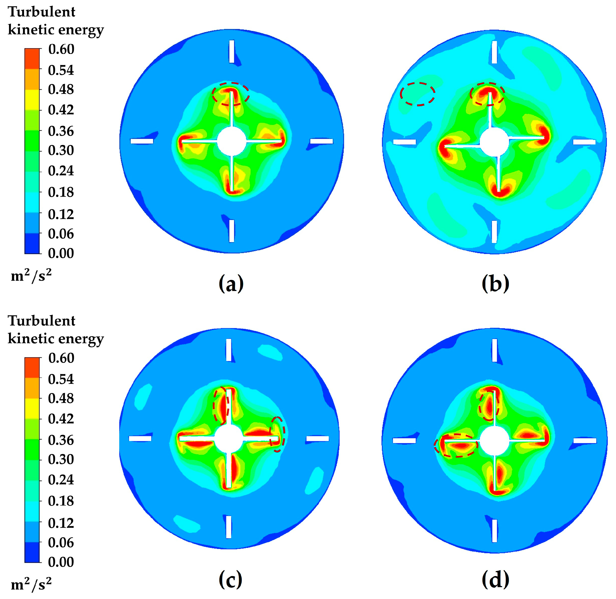
Turbulent kinetic energy governs both the intensity of velocity fluctuations and the rate of energy dissipation, thereby influencing particle collision frequency and shear conditions [7,10,33]. Figure 6 compares the spatial distribution of turbulent kinetic energy (TKE) at z = 30 mm under four blade structures. As observed in Figure 6a,b, the high-TKE regions for the F-C and F-0 blades are localized at the blade tips, with values ranging from 0.54 to 0.6 m2/s2. From these tips, the turbulent kinetic energy decays gradually with radial distance, resulting in a TKE of less than 0.18 m2/s2 across most areas of the tank. However, as shown by the red-dashed area in the figure, applying fractal blade structures effectively improves this distribution.
Figure 6.
The turbulent kinetic energy distribution of four blade structures: (a) F-C; (b) F-0; (c) F-1; (d) F-2.
As shown in Figure 6c,d, the high-TKE region generated by the F-1 blade extends outward, increasing its spatial coverage. This expansion trend reaches its maximum with further fractal iterations. The F-2 blade forms the largest high-TKE zone in the impeller region, maintaining TKE values between 0.3 and 0.6 m2/s2 over a broad area. Consequently, this expanded high-TKE field provides a highly favorable hydrodynamic environment for HIC. This phenomenon increases the collision probability between fine-grained malachite particles and reagents, thereby promoting the formation of hydrophobic aggregates for subsequent flotation [7,34].
Turbulent motion within the stirred tank consists of eddies at various scales [35]. Kolmogorov turbulence theory dictates that energy dissipates through an eddy cascade [36]. The smallest scale of turbulent eddy dissipation (η) is referred to as the Kolmogorov scale. The expression for η is given by Equation (3):
In the equation, v (m2/s) represents the kinematic viscosity, and ε (m2/s3) represents the turbulent energy dissipation rate.
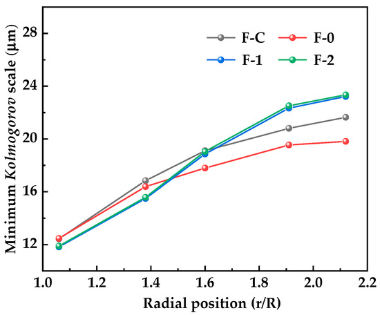
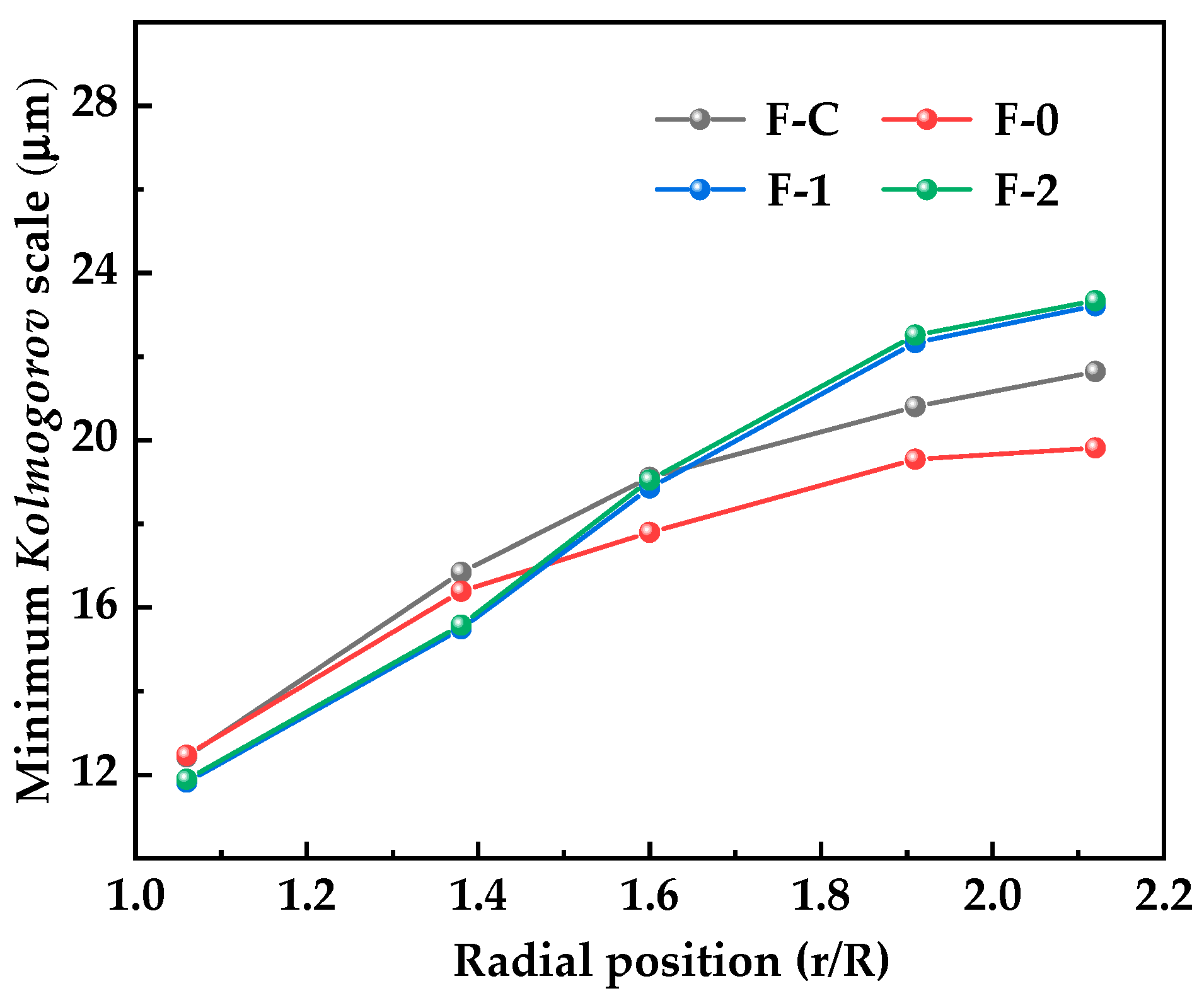
Figure 7 illustrates the distribution of the minimum Kolmogorov scale as a function of radial position. For all four blade configurations, η increases with r/R. The minimum η across the radial positions were observed in the vicinity of the impeller region. Specifically, compared to the conventional F-C blade, the minimum η for the F-1 and F-2 configurations decreased from 12.43 μm to 11.82 μm and 11.89 μm, respectively, indicating a stronger dissipation capacity. Consequently, this enhanced dissipation capability improves energy utilization efficiency and enhances the overall mixing performance of the fluid within the tank [23].
Figure 7.
Distribution of the minimum Kolmogorov scale for four blade structures at different radial positions.
Furthermore, in the near-wall region (r/R = 2.12), the minimum η for the F-1 and F-2 configurations increased by 1.58 μm and 1.7 μm, respectively, compared to the F-C blade. As pointed out by Buffo et al. [35], eddies smaller than the target particle size primarily induce shear effects, whereas those larger than the target particles promote macroscopic mixing. Based on this mechanism, the multi-scale eddy structure generated by the fractal blades provides a synergistic advantage. In the impeller region, it generates strong shear forces that disrupt hydration films on the surfaces of fine particles, thereby facilitating particle collisions. Simultaneously, in the wall region, it induces strong fluid circulation, enhancing overall particle suspension.
3.1.3. Shear Rate Distribution
Previous studies have shown that intense fluid shear provides the turbulent kinetic energy required to overcome interparticle energy barriers [37]. This energy disrupts the hydration films on fine particle surfaces, thereby enhancing reagent adsorption and the formation of hydrophobic aggregates [12,38].
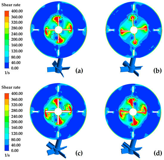
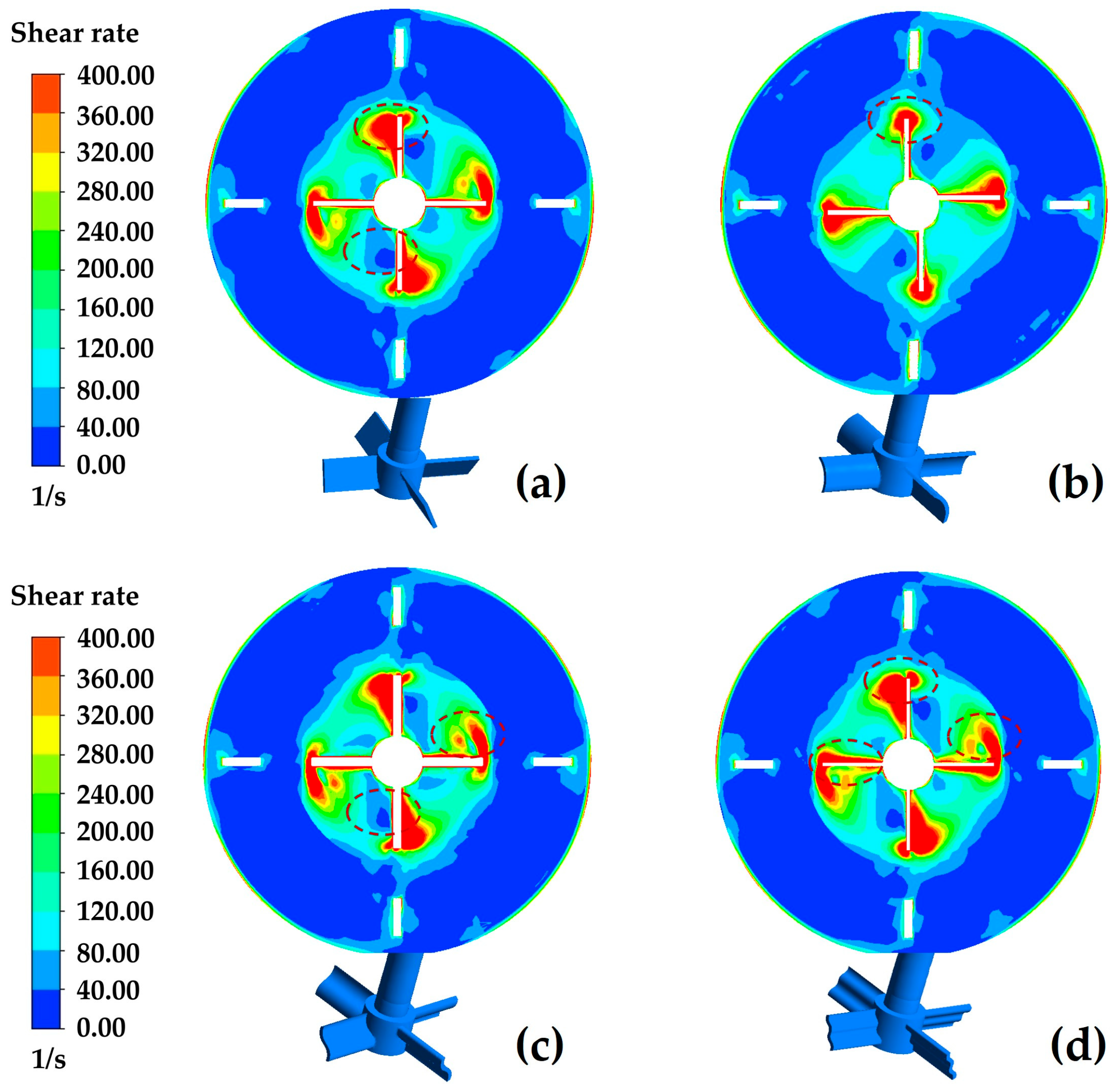
Figure 8 illustrates the spatial distribution of the shear rate at the cross-section of z = 30 mm for the four blade structures. Generally, high shear rates are concentrated at the tips and trailing edges of the blades, with peak values reaching 400 1/s. In contrast, the lowest shear rates appear in the intermediate zone between the impeller and the tank wall, as shown by the red-dashed area in the figure. Compared to the F-C blade, the curved blade F-0 design exhibits a smaller high-shear area. In contrast, the application of fractal blades expands the high-shear zones outward along the blade edges. Among the investigated structures, the F-2 blade yields the largest coverage area of high shear rates.
Figure 8.
The shear rate distribution of four blade structures: (a) F-C; (b) F-0; (c) F-1; (d) F-2.
3.1.4. Volume Fraction Distribution of Malachite Particles
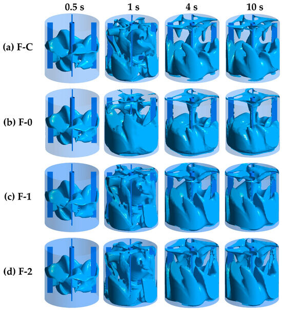
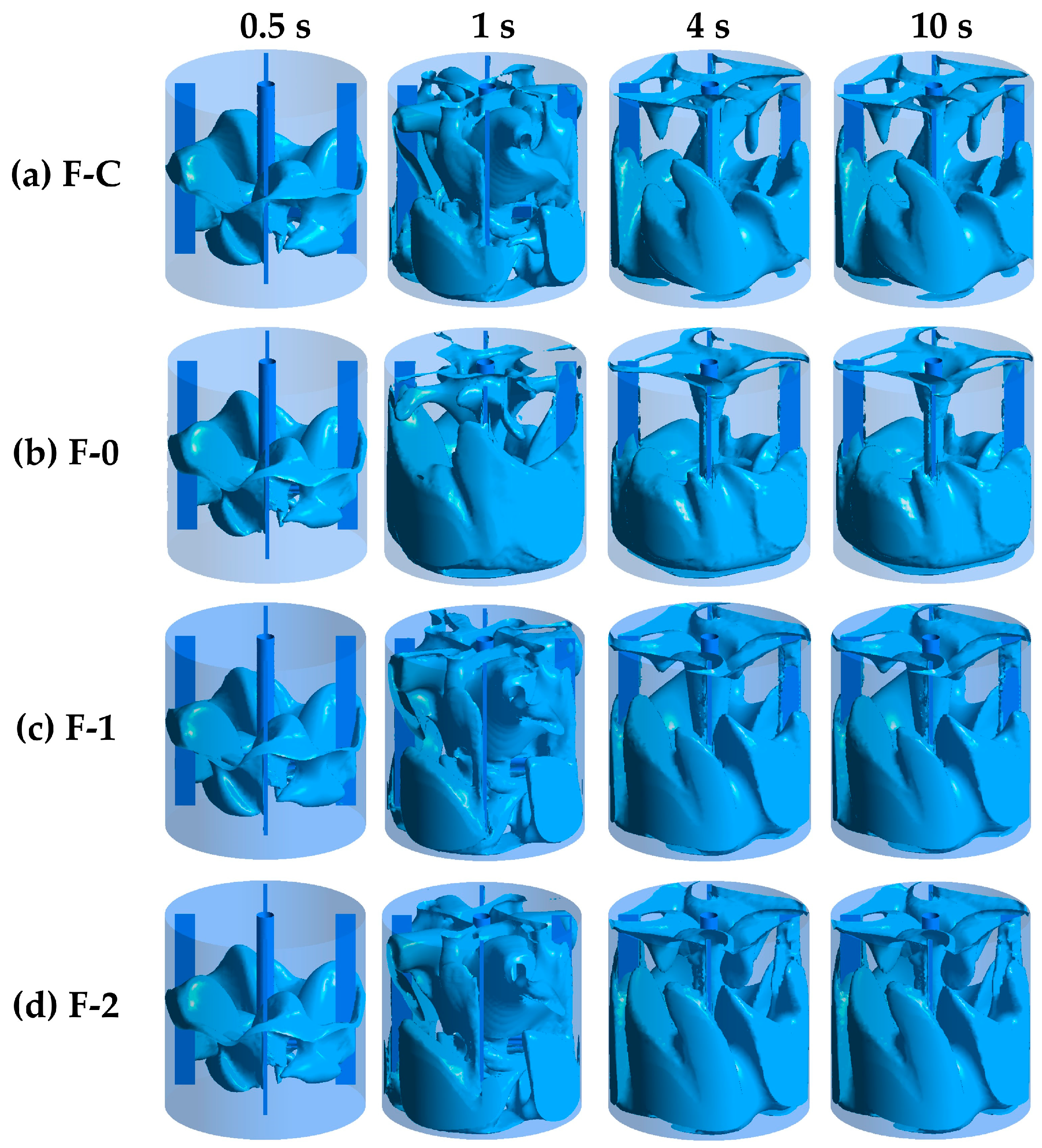
Figure 9 illustrates the temporal evolution of malachite particle isosurfaces under the four blade structures. During the initial phase (0.5 to 1 s), the highly concentrated particles at the tank bottom are transported toward the middle and upper regions, driven primarily by axial pumping and radial fluid convection. Once the stirring time reaches 4 s, the system enters a quasi-steady state, revealing distinct differences in the particle suspension distributions among the different blade structures. Compared to the F-C and F-0 blades, the particle driven by the F-2 achieve the maximum axial suspension and global coverage volume, exhibiting superior macroscopic homogeneity. This observation aligns with the convective transport mechanism reported by Gu et al. [39], indicating that the multi-scale topological structures at the blade edges optimize macroscopic mass transfer and local turbulent dissipation, thereby promoting particle suspension and dispersion.
Figure 9.
The malachite particles distribution of four blade structures.
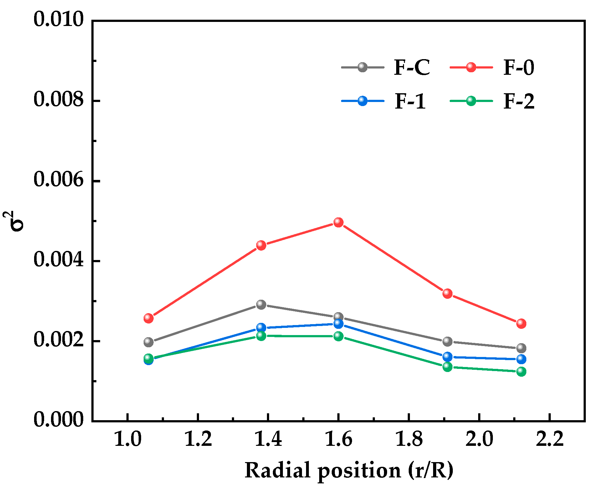
Furthermore, to quantitatively assess the distribution uniformity of malachite particles within the stirred tank, the solid concentration variance (σ2) was used as the evaluation metric [7]. Specifically, 100 evenly spaced sampling points were extracted along the axial height at the radial segment ab. A lower σ2 indicates a more uniform suspension state of the solid particles. The calculation of σ2 is given by Equation (4):
In the equation, k is the sampling point, k = 100; φk is the variance of solid concentration of the sample; φave is the variance of average solid concentration of the sample.
As illustrated in Figure 10, the concentration variance for four blade structures exhibited an initial increase followed by a decrease across the radial positions. At specific radial locations, the F-0 blade reached a maximum σ2 of 0.005 across the entire tank, indicating the poorest mixing performance. Compared to the F-C blade, the minimum σ2 for the F-1 and F-2 configurations decreased from 0.0018 to 0.0015 and 0.0012, respectively. This reduction demonstrates that fractal structures effectively improves the suspension and dispersion of solid particles in the tank. Based on the flow field analyses presented in Section 3.1.1 and Section 3.1.2, this enhanced solid dispersion performance is attributed to the stronger axial and radial flow velocities generated by the fractal blades, along with the expanded regions of high turbulent kinetic energy and the reduced eddy scales.
Figure 10.
The variance in solid-phase concentration of four blade structures.
3.1.5. Agitation Power
The macroscopic flow state and mixing efficiency of the fluid within the stirred tank are governed by the energy input of the system [17,24]. To evaluate the flow conditions in this study, the impeller Reynolds number (Re) is defined as follows:
where ρ (kg/m3) is the density of the stirring medium; d (m) is the impeller diameter; n (r/s) is the rotational speed; and μ (kg/(m·s)) is the dynamic viscosity of the water medium, μ = 0.00103 kg/(m·s).
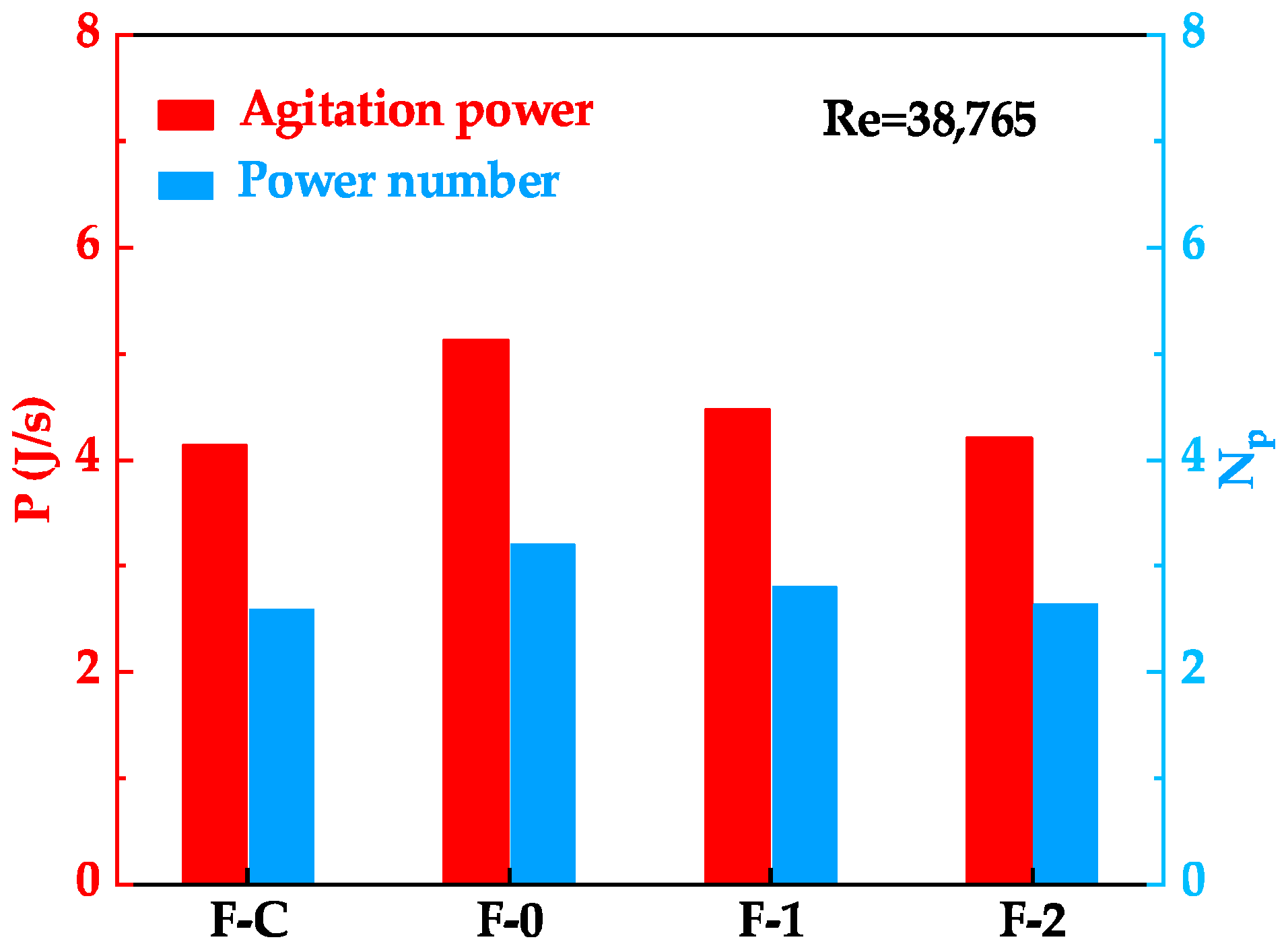
Based on Equation (5), the calculated Re is 38,765, indicating that the system operates in a highly turbulent regime. Under turbulent mixing conditions with a constant Reynolds number, the power consumption of the equipment is positively correlated with the power number (NP). The calculation of NP is given by:
where P (J/s) is the power consumption of the impeller. P is calculated using Equation (7):
where M (N·m) is the torque of the stirred impeller.
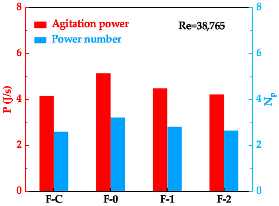
Figure 11 compares the power consumption and power number under the four blade structures at Re = 38,765. Compared to the F-C blade, the F-0 configuration showed higher energy consumption, with P and NP increasing from 4.14 J/s and 2.59 to 5.13 J/s and 3.21, respectively. This increase is primarily due to the curved blade’s larger frontal area, which induces greater fluid resistance.
Figure 11.
The power consumption of four blade structures.
In contrast, the application of the fractal blades F-1 and F-2 resulted in a noticeable reduction in both energy consumption and the power number. Specifically, the stirring power for the F-1 and F-2 blades decreased to 4.48 J/s and 4.21 J/s, with their corresponding NP dropping to 2.81 and 2.63, respectively. This reduction occurs because the multi-scale edge structures effectively optimize the wake-shedding mechanism and mitigate macroscopic flow resistance. As a result, the fractal design achieves a dual benefit by introducing complex curved surfaces to enhance flow-field mixing while simultaneously reducing overall power consumption.
3.2. Interface Properties of Mineral Particles
3.2.1. Results of Adsorption Experiments
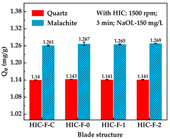
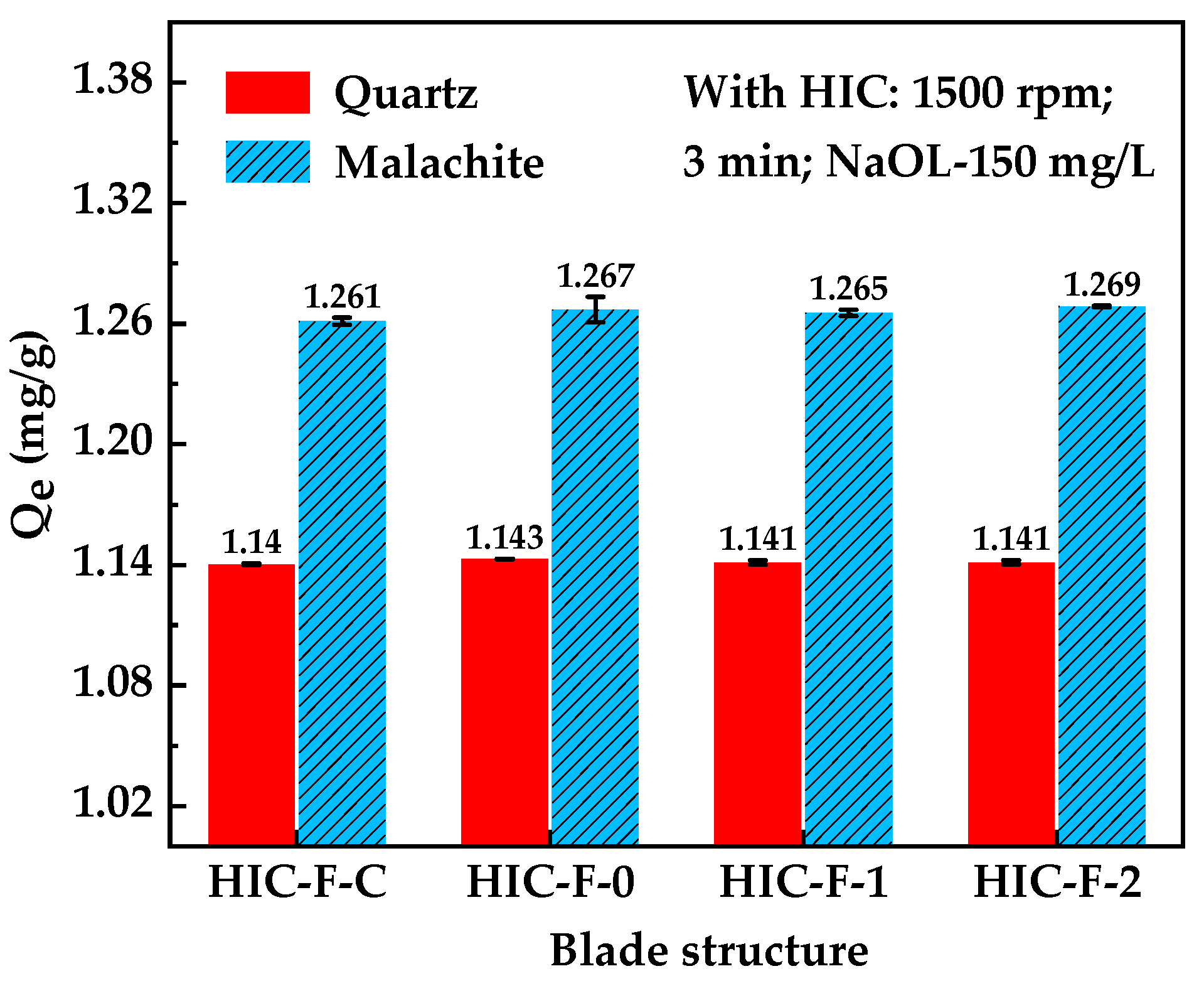
The interaction between mineral surfaces and reagents is governed not only by surface crystal chemistry but also by external hydrodynamic conditions [12,40]. Figure 12 illustrates the effects of the four blade structures on the reagent adsorption amounts on quartz and malachite surfaces during the HIC process. Across all four blade configurations, the NaOL adsorption amount on the quartz surface remained consistently low (approximately 1.140 mg/g) with no significant fluctuations. From an interfacial chemistry perspective, the quartz surface lacks metallic active sites to chemically bind oleate ions. Consequently, its adsorption primarily relies on hydrogen bonding or van der Waals forces, rendering it essentially unresponsive to changes in the flow field structure [41]. In contrast, the malachite surface possesses abundant copper active sites capable of chemisorbing NaOL, resulting in an overall adsorption amount significantly higher than that on quartz [42].
Figure 12.
The effect of blade structures on reagent adsorption on the surfaces of malachite and quartz.
Comparing the specific experimental data, the adsorption amount on the malachite surface slightly increased from 1.261 ± 0.002 mg/g under the conventional F-C blade to 1.269 ± 0.001 mg/g under the F-2 fractal blade. However, although this difference exceeds the experimental error margin, the absolute increment is marginal. These results suggest that the geometric configuration of the blades exerts a limited impact on the final equilibrium adsorption capacity of the mineral.
Previous studies have noted that fine-grained minerals often fail to collide effectively with reagent molecules due to the flow-following effect [6,7]. Consistent with the aforementioned simulation results, the F-2 blade generated smaller eddy scales and expanded the spatial coverage of both high turbulent kinetic energy and high shear rates. These optimized hydrodynamic conditions provide the necessary mechanical energy to overcome the hydration film on fine particle surfaces, thereby increasing the collision probability between particles and reagents. Consequently, while the fractal design has a limited impact on increasing the absolute adsorption capacity, it effectively improves the physical environment for reagent attachment by optimizing the microscopic flow field.
3.2.2. Aggregation Behavior of the Particles
Numerous studies have shown that increasing the apparent particle size through aggregation significantly improves flotation efficiency, a process influenced by the hydrodynamic environment during pulp conditioning [13,43]. Figure 13 and Figure 14 present the aggregate images and particle size distributions, respectively, for the four blade structures under HIC.
Figure 13.
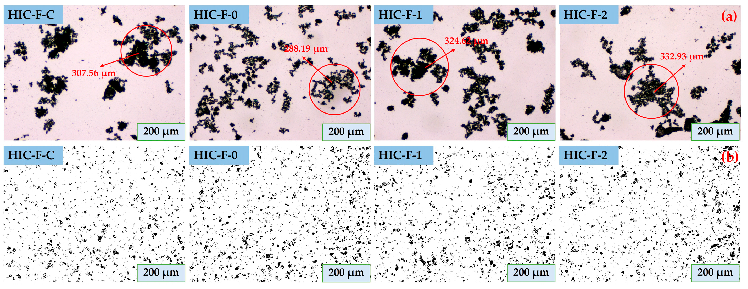
The effect of blade structure on the aggregation behavior of mineral particles: (a) malachite; (b) quartz.
Figure 14.
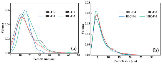
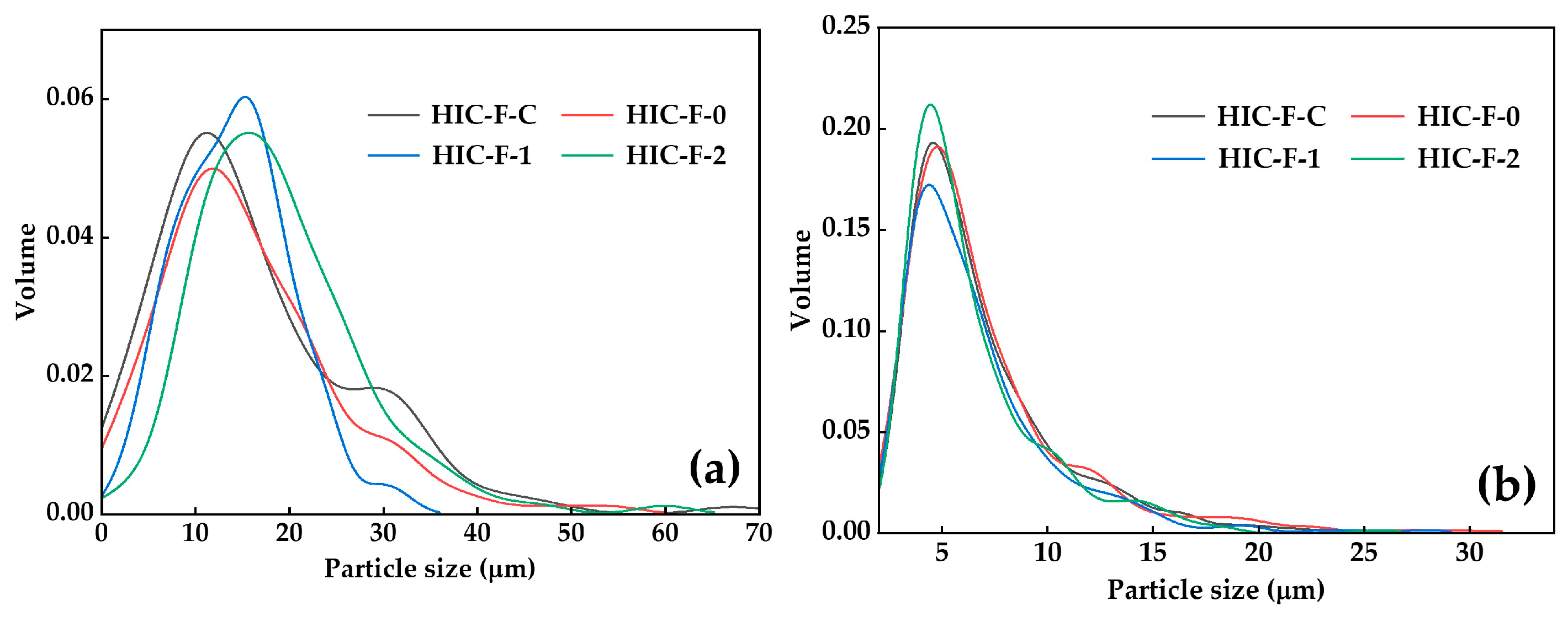
The particle size distribution of four blade structures: (a) malachite; (b) quartz.
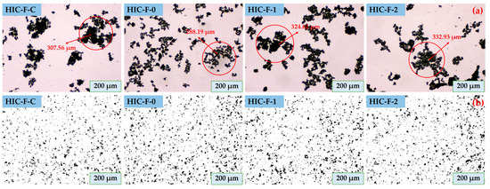
As illustrated in Figure 13, the aggregate size generated by the F-C blade was 307.56 μm. For the F-0 blade, due to insufficient local turbulent kinetic energy and shear rates, the aggregate size decreased to 288.19 μm, exhibiting a higher porosity and a looser structure. In contrast, the fractal blades enhanced particle aggregation, with the F-2 blade producing the largest and most compact aggregates. The particle size distributions in Figure 14 corroborate this trend. Specifically, as the number of fractal iterations increased, the malachite volume distribution peak shifted toward larger particle sizes.
Regarding the fine-grained quartz minerals, microscopic observations revealed no distinct agglomerates; the particles remained highly dispersed even under HIC (Figure 13b). It occurs because of the weak adsorption capacity of NaOL on the quartz surface. Furthermore, the quartz particle size distribution curves across all blade structures highly overlapped, with the volume peaks consistently stabilizing at approximately 5 μm.
3.3. Flotation Test
3.3.1. Pure Mineral Testing
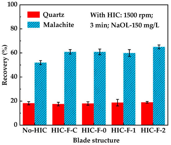
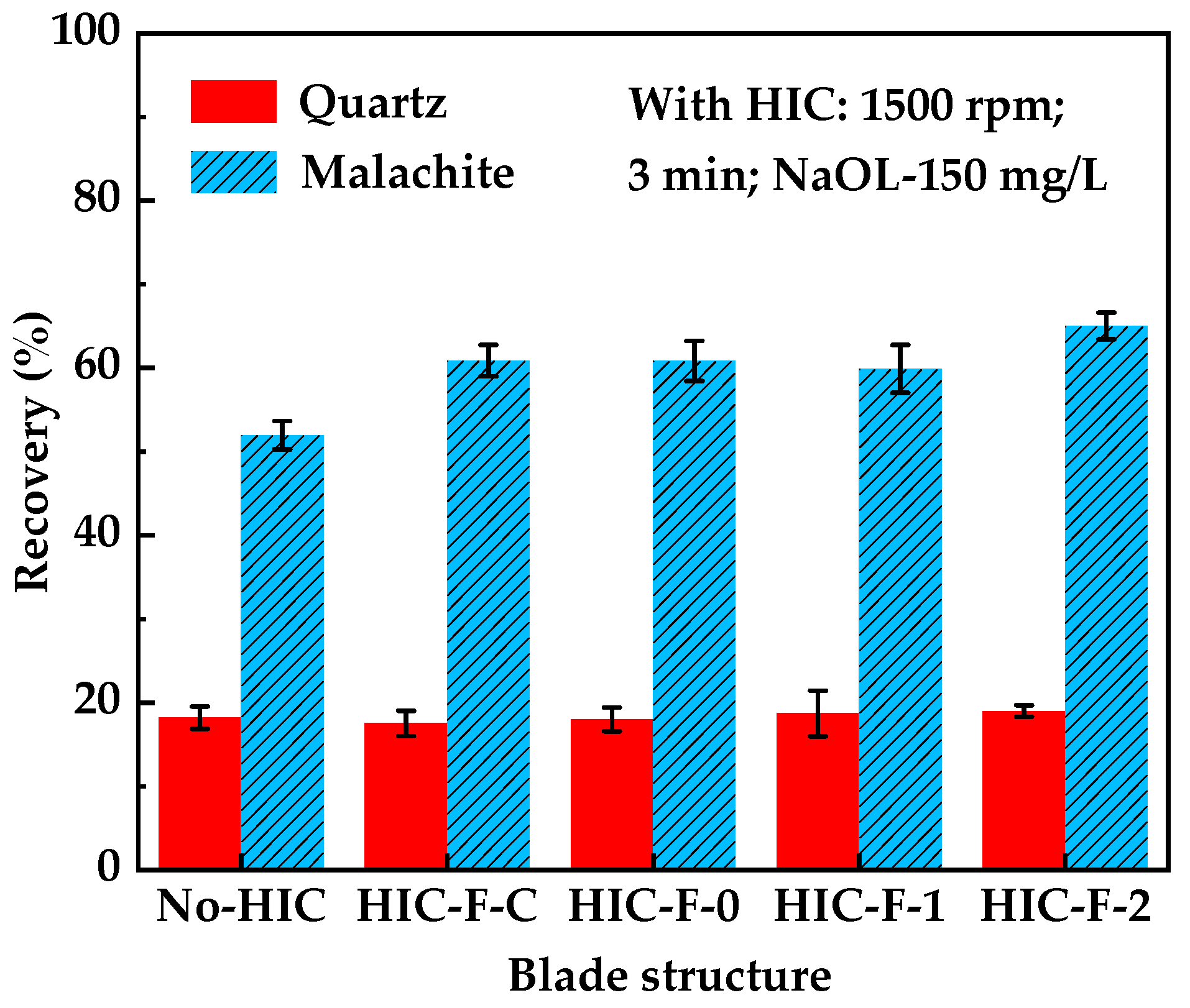
The synergy between interfacial chemistry and hydrodynamics governs the flotation process [10,44]. Figure 15 illustrates the effects of the four blade structures on the flotation recovery of fine-grained quartz and malachite. The recovery remained stable at approximately 18% under either HIC or blade structure optimization. The differences among all groups fell within the experimental error range, indicating their inherently low floatability and minimal response to the flow field.
Figure 15.
The effect of blade structure on the flotation behavior of fine-grained malachite and quartz.
In contrast, the flotation behavior of malachite was significantly influenced by the flow field distributions. Without HIC, the recovery of fine-grained malachite was only 51.98 ± 1.69%. Following HIC with the conventional F-C blade, the recovery increased to 60.90 ± 1.88%. The malachite recovery showed no statistically significant differences with the application of the F-0 and F-1 blades. However, applying the F-2 blade further improved recovery to 65.03 ± 1.6%. This increment exceeded the experimental error margin, indicating that the F-2 blade structure exhibits superior flotation performance.
3.3.2. Artificially Blended Ore Testing
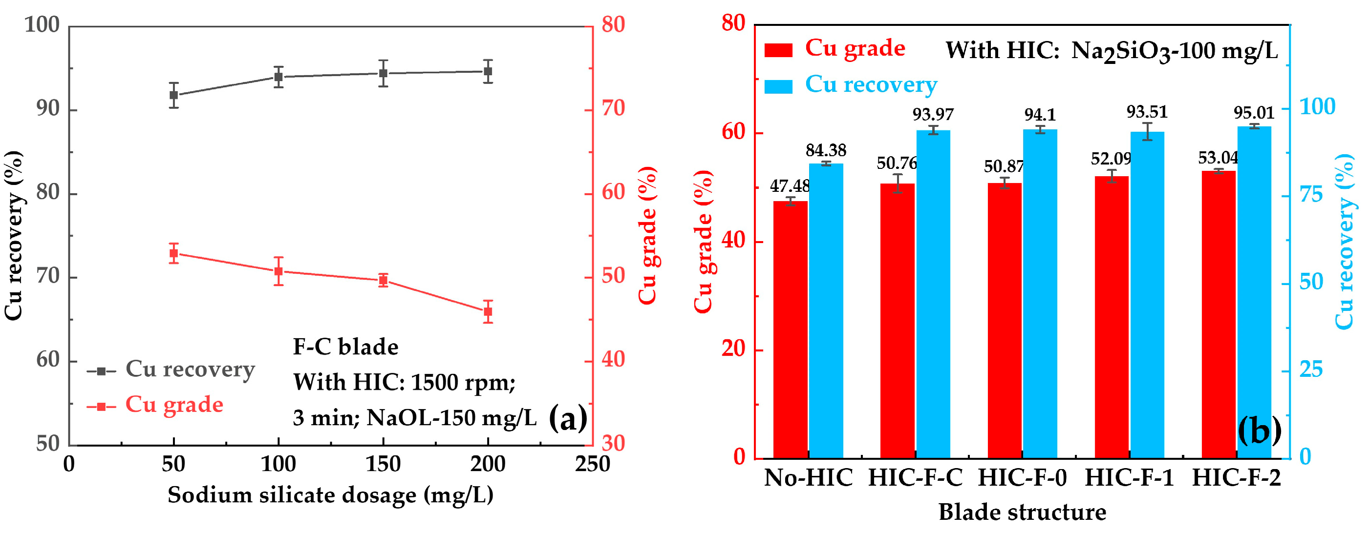
Figure 16a illustrates the effect of sodium silicate dosage on the separation indices of the artificial mixed ore under the F-C blade structure. The Cu recovery stabilized at approximately 94% upon reaching a sodium silicate concentration of 100 mg/L. However, when the reagent dosage was further increased to 200 mg/L, the Cu concentrate grade decreased linearly. This phenomenon is attributed to the dispersion effect of sodium silicate [45]. While it effectively disperses quartz to prevent hetero-coagulation, excessive dispersion causes gangue particles to break down into ultrafine particles. These fine particles are prone to mechanical entrainment, thereby deteriorating the concentrate grade.
Figure 16.
Effect of (a) sodium silicate dosage and (b) blade structures on copper grade and recovery.
Figure 16b compares the macroscopic effects of the four blade structures on the flotation indices at the optimal sodium silicate dosage of 100 mg/L. Compared to without HIC, the introduction of HIC-F-C blade improved the separation performance, with the Cu grade and recovery increasing by 3.28 ± 0.54% and 9.59 ± 1.23%, respectively. Furthermore, the differences in grade and recovery between the F-0 and F-C systems fell within the experimental error range, indicating that the simple curved blade did not yield a substantial improvement. In contrast, the fractal blades exhibited superior separation performance. Specifically, the Cu grade increased from 50.76 ± 1.67% in the F-C system to 53.04 ± 0.39% in the F-2 system, while the Cu recovery slightly increased from 93.97 ± 1.23% to 95.01 ± 0.62%.
In summary, the F-2 fractal blade promoted the selective aggregation of malachite by regulating the flow field while maintaining the dispersed state of quartz. This hydrodynamic optimization enlarged the difference in apparent particle sizes between the two minerals, thereby improving the final flotation separation. From an industrial application perspective, the fractal blades designed in this study enhance fine particle separation without increasing macroscopic power consumption or reagent costs. Consequently, this provides a viable equipment modification strategy for cost reduction and efficiency enhancement in actual mineral processing plants.
3.4. Mechanism of Enhancing Fine-Grained Malachite Flotation by Optimizing the HIC Process with Fractal Blades
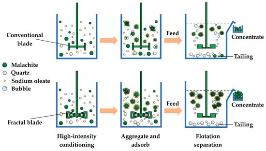
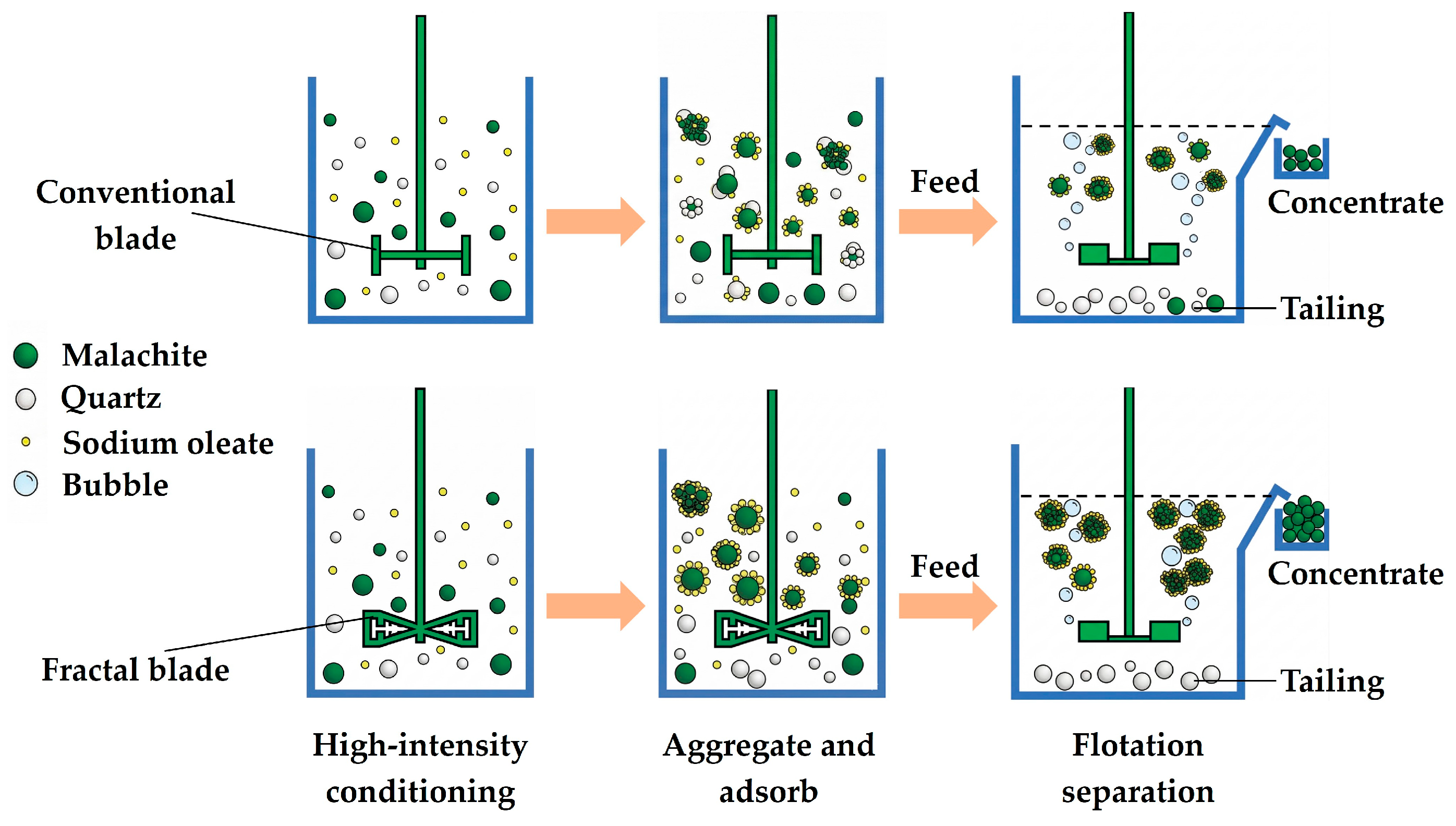
Based on the CFD numerical simulations and interfacial behavior characterizations, Figure 17 illustrates the flotation separation mechanism of fine-grained malachite and quartz enhanced by the fractal blades.
Figure 17.
Mechanism of enhanced flotation separation of fine-grained malachite and quartz by fractal blades.
During the HIC of fine-grained malachites, the insufficient TKE and local shear rates generated by conventional rectangular blades fail to disrupt the hetero-coagulation between quartz and malachite. This non-selective aggregation ultimately deteriorates the subsequent flotation separation performance. In contrast, the application of fractal blades alters the energy dissipation mode by regulating the flow field distribution (Figure 4). It generates stronger fluid squeezing and collision effects in localized regions, expands the high-TKE zones, and consequently enhances particle suspension and dispersion (Figure 9). Furthermore, the intense local shear forces generated by this multi-scale flow field provide the mechanical energy needed to overcome interparticle energy barriers, facilitating the detachment of quartz slime coatings from the malachite surfaces. This cleaning effect facilitates the diffusion and interaction of malachite particles with NaOL, resulting in a slight increase in reagent adsorption (Figure 12). Subsequently, the optimized hydrodynamic environment promotes the selective aggregation of malachite into larger structures, while the gangue quartz remains dispersed. Finally, it improves both the grade and recovery of the Cu concentrate (Figure 16).
Although this core hydrodynamic enhancement mechanism has been systematically revealed in the current system, certain limitations remain. The current flotation evaluation relies on pure-mineral and binary-mixed-ore models. Additionally, the CFD simulations focused solely on liquid–solid two-phase flow to investigate mixing during the conditioning stage. In actual industrial production, complex polymetallic dissemination characteristics, variable water-chemistry environments, and dynamic bubble behavior in gas–liquid–solid three-phase flows can significantly impact final flotation performance. Therefore, future research should focus on developing complex three-phase flow coupled computational models and validating them using actual, complex ore systems. Ultimately, this will provide more comprehensive theoretical support for the industrial scale-up and engineering applications of fractal blade structures.
4. Conclusions
In this study, novel fractal blades were introduced into the HIC process to investigate the mechanisms by which flow field regulation enhances flotation separation of fine-grained malachite and quartz. Based on fluid dynamics simulations and interfacial behavior characterizations, the main conclusions are drawn as follows:
- (1)
- The multi-scale edge structures of the fractal blade optimized the energy dissipation mode of the HIC process. Compared to the F-0 blade, the fractal designs decreased the power number while expanding the high-TKE regions along the radial positions, thereby reducing the minimum Kolmogorov scale. Furthermore, they generated higher axial flow velocities in the impeller region, thereby improving the homogeneity of the solid particle suspension.
- (2)
- The intensified turbulent flow field generated by fractal blades enhanced flotation performance. The intense shear forces generated by these blades increased the particle-reagent collision probability, which facilitated reagent adsorption and the formation of larger aggregates. Consequently, under conditioning at 1500 rpm for 3 min in the single mineral flotation system, the malachite recovery increased from 60.90 ± 1.88% with the conventional F-C blade to 65.03 ± 1.60% with the F-2 fractal blade.
- (3)
- The fractal blade design improves flotation separation of fine-grained malachite from quartz by regulating the hydrodynamic environment. The artificially blended ore flotation revealed that, at an equivalent energy input, the F-2 blade improved the Cu concentrate grade and recovery by 2.28 ± 1.28% and 1.04 ± 0.61%, respectively, compared with the conventional F-C system. Ultimately, this work demonstrates that geometrically optimizing the blade can enhance separation efficiency without increasing energy consumption, thereby offering a reliable engineering reference for industrial fine-grained mineral processing.
Author Contributions
Conceptualization, G.G., Y.C., Y.W. (Yanming Wu) and Y.W. (Yanhong Wang); methodology, Y.W. (Yanhong Wang), S.Y., C.O. and B.L. (Bingchao Lv), software, B.L. (Binqing Liu) and Y.C.; validation, G.G., Y.W. (Yanming Wu), Y.C., Y.W. (Yanhong Wang), Y.Y., S.Y., C.O. and B.L. (Bingchao Lv); formal analysis, G.G., Y.W. (Yanming Wu) and Y.C.; investigation, G.G.; resources, G.G. and Y.C.; data curation, Y.W. (Yanming Wu); writing—original draft preparation, B.L. (Binqing Liu); writing—review and editing, B.L. (Binqing Liu); visualization, Y.W. (Yanhong Wang); supervision, Y.W. (Yanming Wu); project administration, G.G., Y.C. and Y.W. (Yanming Wu); funding acquisition, G.G., Y.C. and Y.W. (Yanhong Wang). All authors have read and agreed to the published version of the manuscript.
Funding
The research was funded by Provincial Special Project for the Construction of the National Sustainable Development Agenda Innovation Demonstration Zone in Chenzhou (No. 2023sfq49); National Natural Science Foundation of China (No. 52074358).
Data Availability Statement
The original contributions presented in this study are included in the article. Further inquiries can be directed to the corresponding authors.
Acknowledgments
The authors acknowledge financial support from the Provincial Special Project for the Construction of the National Sustainable Development Agenda Innovation Demonstration Zone in Chenzhou (No. 2023sfq49); National Natural Science Foundation of China (No. 52074358). This research was carried out in part using computing resources at the High Performance Computing Center of Central South University.
Conflicts of Interest
Author Yuan Chen was employed by the company Shunshui Environmental Governance Co., Ltd. Authors Yanming Wu, Yuankun Yang, Shengli Yu, Chongzhong Ouyang and Bingchao Lv were employed by the company Zijin Mining Group Co., Ltd. The remaining authors declare that the research was conducted in the absence of any commercial or financial relationships that could be construed as a potential conflict of interest.
Abbreviations
The following abbreviations are used in this manuscript:
| HIC | High-intensity conditioning |
| F-C | Conventional rectangular blade |
| F-0 | Zero-order fractal blade |
| F-1 | First-order fractal blade |
| F-2 | Second-order fractal blade |
References
- Northey, S.; Mohr, S.; Mudd, G.M.; Weng, Z.; Giurco, D. Modelling future copper ore grade decline based on a detailed assessment of copper resources and mining. Resour. Conserv. Recycl. 2014, 83, 190–201. [Google Scholar] [CrossRef] [Scilit]
- Klose, S.; Pauliuk, S. Sector-level estimates for global future copper demand and the potential for resource efficiency. Resour. Conserv. Recycl. 2023, 193, 106941. [Google Scholar] [CrossRef] [Scilit]
- Zhang, L.; Cai, Z.; Yang, J.; Yuan, Z.; Chen, Y. The future of copper in China—A perspective based on analysis of copper flows and stocks. Sci. Total Environ. 2015, 536, 142–149. [Google Scholar] [CrossRef] [Scilit]
- Jacques, S.; Greet, C.J.; Bastin, D. Oxidative weathering of a copper sulphide ore and its influence on pulp chemistry and flotation. Miner. Eng. 2016, 99, 52–59. [Google Scholar] [CrossRef] [Scilit]
- Liu, C.; Zhu, G.; Song, S.; Li, H. Interaction of gangue minerals with malachite and implications for the sulfidization flotation of malachite. Colloids Surf. A Physicochem. Eng. Asp. 2018, 555, 679–684. [Google Scholar] [CrossRef] [Scilit]
- Forbes, E. Shear, selective and temperature responsive flocculation: A comparison of fine particle flotation techniques. Int. J. Miner. Process. 2011, 99, 1–10. [Google Scholar] [CrossRef] [Scilit]
- Li, Q.; Zhou, J.; Wu, Y.; Yang, Y.; Wang, Y.; Gu, G.; Liu, B. Influence of the impeller structure and operating parameters of a high intensity conditioning system on the flotation of fine-grained pyrite. Miner. Eng. 2025, 228, 109363. [Google Scholar] [CrossRef] [Scilit]
- Sun, W.; Hu, Y.-h.; Dai, J.-p.; Liu, R.-q. Observation of fine particle aggregating behavior induced by high intensity conditioning using high speed CCD. Trans. Nonferr. Met. Soc. China 2006, 16, 198–202. [Google Scholar] [CrossRef] [Scilit]
- Yu, Y.; Ma, L.; Wu, L.; Ye, G.; Sun, X. The role of surface cleaning in high intensity conditioning. Powder Technol. 2017, 319, 26–33. [Google Scholar] [CrossRef] [Scilit]
- Yang, L.; Li, W.; Li, X.; Yan, X.; Zhang, H. Effect of the turbulent flow pattern on the interaction between dodecylamine and quartz. Appl. Surf. Sci. 2020, 507, 145012. [Google Scholar] [CrossRef] [Scilit]
- Zhao, J.; Hu, Y.; Liu, J.; Wang, J. Hydrophobic Flocculation of Coal Particles Controlled by Mechanical Stirring. Miner. Process. Extr. Metall. Rev. 2022, 44, 565–570. [Google Scholar] [CrossRef] [Scilit]
- Chen, W.; Feng, Q.; Zhang, G.; Li, L.; Jin, S. Effect of energy input on flocculation process and flotation performance of fine scheelite using sodium oleate. Miner. Eng. 2017, 112, 27–35. [Google Scholar] [CrossRef] [Scilit]
- Shen, Z.; Zhang, Q. Hydrophobic agglomeration behavior of rhodochrosite fines Co-induced by oleic acid and shearing. Sep. Purif. Technol. 2022, 282, 120115. [Google Scholar] [CrossRef] [Scilit]
- Li, Q.; Du, S.; Gu, G.; Wu, L.; Wang, Y. Utilizing the high intensity conditioning process with a multi-bladed impeller to enhance the flotation of fine-grained galena. Part. Sci. Technol. 2023, 42, 895–907. [Google Scholar] [CrossRef] [Scilit]
- Zhao, J.; Gao, Z.; Bao, Y. Effects of the Blade Shape on the Trailing Vortices in Liquid Flow Generated by Disc Turbines. Chin. J. Chem. Eng. 2011, 19, 232–242. [Google Scholar] [CrossRef] [Scilit]
- Nedić, J.; Ganapathisubramani, B.; Vassilicos, J.C. Drag and near wake characteristics of flat plates normal to the flow with fractal edge geometries. Fluid Dyn. Res. 2013, 45, 061406. [Google Scholar] [CrossRef] [Scilit]
- Başbuğ, S.; Papadakis, G.; Vassilicos, J.C. Reduced power consumption in stirred vessels by means of fractal impellers. AIChE J. 2018, 64, 1485–1499. [Google Scholar] [CrossRef] [Scilit]
- Hoseini, S.S.; Najafi, G.; Ghobadian, B.; Akbarzadeh, A.H. Impeller shape-optimization of stirred-tank reactor: CFD and fluid structure interaction analyses. Chem. Eng. J. 2021, 413, 127497. [Google Scholar] [CrossRef] [Scilit]
- Ameur, H.; Vial, C. Modified scaba 6SRGT impellers for process intensification: Cavern size and energy saving when stirring viscoplastic fluids. Chem. Eng. Process.-Process Intensif. 2020, 148, 107795. [Google Scholar] [CrossRef] [Scilit]
- Wang, Z.; Li, D.; Gao, Q.; Yang, Q.; Xiong, X.; Jiang, C.; Zhang, F. Study of the flow field of a new fishtail-type stirring impeller in a stirred tank. Chem. Eng. Process.-Process Intensif. 2023, 194, 109577. [Google Scholar] [CrossRef] [Scilit]
- Gu, D.; Liu, Z.; Xu, C.; Li, J.; Tao, C.; Wang, Y. Solid-liquid mixing performance in a stirred tank with a double punched rigid-flexible impeller coupled with a chaotic motor. Chem. Eng. Process. Process Intensif. 2017, 118, 37–46. [Google Scholar] [CrossRef] [Scilit]
- Pakzad, L.; Ein-Mozaffari, F.; Chan, P. Using electrical resistance tomography and computational fluid dynamics modeling to study the formation of cavern in the mixing of pseudoplastic fluids possessing yield stress. Chem. Eng. Sci. 2008, 63, 2508–2522. [Google Scholar] [CrossRef] [Scilit]
- Yang, S.; Ma, W.; Chai, W.; Cao, Y. Hydrodynamics intensification and interface control in the flotation conditioning process using fractal impellers. Sep. Purif. Technol. 2024, 328, 125043. [Google Scholar] [CrossRef] [Scilit]
- Steiros, K.; Bruce, P.J.K.; Buxton, O.R.H.; Vassilicos, J.C. Power consumption and form drag of regular and fractal-shaped turbines in a stirred tank. AIChE J. 2016, 63, 843–854. [Google Scholar] [CrossRef] [Scilit]
- Pukkella, A.K.; Vysyaraju, R.; Tammishetti, V.; Rai, B.; Subramanian, S. Improved mixing of solid suspensions in stirred tanks with interface baffles: CFD simulation and experimental validation. Chem. Eng. J. 2019, 358, 621–633. [Google Scholar] [CrossRef] [Scilit]
- Launder, B.E.; Spalding, D.B. Lectures in Mathematical Model of Turbulence; Academic Press: Cambridge, MA, USA, 1972. [Google Scholar]
- Gidaspow, D.; Bezburuah, R.; Ding, J. Hydrodynamics of Circulating Fluidized Beds: Kinetic Theory Approach; Department of Chemical Engineering, Illinois Institute of Technology: Chicago, IL, USA, 1991. [Google Scholar]
- Sun, W.; Xie, Z.-J.; Hu, Y.-H.; Deng, M.-J.; Yi, L.; He, G.-Y. Effect of high intensity conditioning on aggregate size of fine sphalerite. Trans. Nonferr. Met. Soc. China 2008, 18, 438–443. [Google Scholar] [CrossRef] [Scilit]
- Ni, C.; Zhang, Q.; Jin, M.; Xie, G.; Peng, Y.; Yu, H.; Bu, X. Effect of high-speed shear flocculation on the flotation kinetics of ultrafine microcrystalline graphite. Powder Technol. 2022, 396, 345–353. [Google Scholar] [CrossRef] [Scilit]
- Ozkan, A.; Ucbeyiay, H.; Aydogan, S. Shear flocculation of celestite with anionic surfactants and effects of some inorganic dispersants. Colloids Surf. A Physicochem. Eng. Asp. 2006, 281, 92–98. [Google Scholar] [CrossRef] [Scilit]
- Yu, Z.; Peng, L.; Zhang, B.; Zou, P.; Hu, Z.; Ji, Y.; Yang, D.; Yu, X. Rutile-quartz separation in benzohydroxamic acid and sodium oleate flotation systems. Next Mater. 2025, 8, 100525. [Google Scholar] [CrossRef] [Scilit]
- Huang, G.; Liu, J.; Wang, L.; Song, Z. Flow field simulation of agitating tank and fine coal conditioning. Int. J. Miner. Process. 2016, 148, 116–123. [Google Scholar] [CrossRef] [Scilit]
- Tabosa, E.; Runge, K.; Holtham, P.; Duffy, K. Improving flotation energy efficiency by optimizing cell hydrodynamics. Miner. Eng. 2016, 96–97, 194–202. [Google Scholar] [CrossRef] [Scilit]
- Li, S.; Schwarz, M.P.; Feng, Y.; Witt, P.; Sun, C. Numerical investigations into the effect of turbulence on collision efficiency in flotation. Miner. Eng. 2021, 163, 106744. [Google Scholar] [CrossRef] [Scilit]
- Buffo, M.M.; Corrêa, L.J.; Esperança, M.N.; Cruz, A.J.G.; Farinas, C.S.; Badino, A.C. Influence of dual-impeller type and configuration on oxygen transfer, power consumption, and shear rate in a stirred tank bioreactor. Biochem. Eng. J. 2016, 114, 130–139. [Google Scholar] [CrossRef] [Scilit]
- Kolmogorov, A.N. The Local Structure of Turbulence in Incompressible Viscous Fluid for Very Large Reynolds Numbers. Proc. R. Soc. A Math. 1991, 434, 9–13. [Google Scholar] [CrossRef] [Scilit]
- Warren, L.J. Shear-Flocculation of Ultrafine Scheelite in Sodium Oleate Solutions. J. Colloid Interface Sci. 1975, 50, 307–318. [Google Scholar] [CrossRef] [Scilit]
- Bulatovic, S.M.; Salter, R.S. High intensity conditioning—A new approach to improving flotation of mineral slimes. In Processing of Complex Ores; Pergamon Press: Oxford, UK, 1989; pp. 169–181. [Google Scholar]
- Gu, D.; Chen, J.; Song, Y.; Chen, Q. Modification of impeller blades for the efficient mixing of particulate suspensions in a stirred tank. Adv. Powder Technol. 2024, 35, 104444. [Google Scholar] [CrossRef] [Scilit]
- Long, Q.; Wang, H.; Wang, X.; Jiang, F.; Zhang, J.; Zou, L.; Wang, Q.; Sun, Z.; Zhang, Y.; Lu, W.; et al. A novel switchable collector for selective flotation of fine copper oxide from silica. Miner. Eng. 2023, 199, 108104. [Google Scholar] [CrossRef] [Scilit]
- Feng, Q.; Wen, S.; Zhao, W.; Chen, Y. Effect of calcium ions on adsorption of sodium oleate onto cassiterite and quartz surfaces and implications for their flotation separation. Sep. Purif. Technol. 2018, 200, 300–306. [Google Scholar] [CrossRef] [Scilit]
- Choi, J.; Choi, S.Q.; Park, K.; Han, Y.; Kim, H. Flotation behaviour of malachite in mono- and di-valent salt solutions using sodium oleate as a collector. Int. J. Miner. Process. 2016, 146, 38–45. [Google Scholar] [CrossRef] [Scilit]
- Jin, S.; Ou, L. Comparison of the Effects of Sodium Oleate and Benzohydroxamic Acid on Fine Scheelite and Cassiterite Hydrophobic Flocculation. Minerals 2022, 12, 687. [Google Scholar] [CrossRef] [Scilit]
- Zhao, G.; Feng, B.; Qiu, T.; Zhu, D.; Li, X.; Gao, Z.; Yan, H.; Wu, H. Enhanced flotation separation pyrrhotite from serpentine by fluid force field. Colloids Surf. A Physicochem. Eng. Asp. 2022, 651, 129711. [Google Scholar] [CrossRef] [Scilit]
- Yuan, Z.; Du, Y.; Meng, Q.; Yu, L. Influence of sodium silicate on the selective dispersion and flotation separation of ilmenite against fine titanaugite in hydrophobic systems. Appl. Surf. Sci. 2025, 680, 161348. [Google Scholar] [CrossRef] [Scilit]


Disclaimer/Publisher’s Note: The statements, opinions and data contained in all publications are solely those of the individual author(s) and contributor(s) and not of MDPI and/or the editor(s). MDPI and/or the editor(s) disclaim responsibility for any injury to people or property resulting from any ideas, methods, instructions or products referred to in the content. |
© 2026 by the authors. Licensee MDPI, Basel, Switzerland. This article is an open access article distributed under the terms and conditions of the Creative Commons Attribution (CC BY) license.