


Abstract
Grain-scale heterogeneity strongly influences hydraulic fracture initiation and trajectory in crystalline rocks, yet its contributions to non-planar growth and the interaction of multiple nearby cracks remain insufficiently quantified. To address this gap, we perform numerical experiments on a model containing two parallel pre-existing cracks using a hydro-mechanical phase-field framework, systematically quantifying how mineral distribution and axial compression govern non-planar hydraulic fracture growth and inter-fracture competition. The results demonstrate that mineral distribution is the primary driver of fracture complexity. Even within the same Voronoi tessellation, redistributing minerals alone yields markedly different trajectories, deflections, branching patterns, and final morphologies. Furthermore, non-planar growth follows a stepwise, energy-threshold-driven mechanism. When cracks penetrate strong grains or undergo large-angle deflections, propagation is impeded, and injection pressure builds up. Once a critical energy threshold is reached, accumulated energy is rapidly released along the path of minimum incremental energy, manifested as abrupt pressure drops and rapid crack advance. Additionally, the two nearby fractures exhibit strong mechanical competition. Despite negligible hydraulic interference in low-permeability granite, early growth of one fracture redistributes stresses and suppresses the driving force of the other, resulting in asymmetric development. Finally, axial compression primarily governs the overall propagation orientation and influences local failure modes but has a limited effect on peak pressure relative to mineral distribution.
1. Introduction
Hydraulic fracturing is a key subsurface engineering technique that enhances permeability and reshapes fluid pathways. It has been widely applied in unconventional energy extraction, geothermal development, and deep underground construction [1,2,3,4,5]. However, its engineering predictability largely depends on how fractures initiate and propagate in real, heterogeneous rocks. In crystalline rocks, heterogeneity is mainly manifested in the distribution of mineral grains. Mechanical contrasts among minerals can perturb the local stress and pressure fields near the crack tip, promoting tortuous, non-planar trajectories and leading to pronounced scatter in fracture paths and breakdown responses [6,7,8,9,10]. Therefore, to improve the controllability and predictability of hydraulic fracturing in heterogeneous crystalline formations, it is essential to clarify the mechanisms by which mineral distribution governs fracture initiation conditions and propagation path selection.
With continued advances in loading, sensing, and imaging techniques, laboratory experiments have become a feasible and effective approach for investigating hydraulic fracturing in heterogeneous rocks. Acoustic emission (AE) records transient elastic waves released during microcrack nucleation, growth, and coalescence, enabling spatiotemporal localization of damage and time-resolved tracking of fracture-mode transitions during pressurization [11,12]. X-ray computed tomography (CT) and scanning electron microscopy (SEM) can further characterize and reconstruct mineral-scale textures and microcrack features within specimens [13,14]. Digital image correlation (DIC) provides full-field surface displacement and strain maps, allowing visualization of strain localization and crack opening/deflection as fractures interact with heterogeneous domains [15,16,17]. However, experimental methodologies face inherent challenges in controlling specific variables and isolating confounding factors, leading to considerable variability. Numerical simulations thus provide a complementary approach for systematic investigation.
About traditional analytical methods for hydraulic fracturing, such as the Perkins-Kern–Nordgren (PKN) model, Khristianovic–Geertsma–de Klerk (KGD) model and radial fracture model. They were developed under simplifying assumptions of homogeneous, isotropic rock media and planar fracture geometries. While these models laid the foundation for understanding hydraulic fractures, they fail to capture the complexities of fracture propagation in heterogeneous and anisotropic rocks [18,19].
Because it enables precise, independent control of key variables conveniently and cost-effectively, numerical simulation has become an indispensable tool. In general, mainstream approaches can be grouped into continuum, discontinuum, and hybrid continuum-discontinuum methods. Continuum methods, represented by the finite element method (FEM) [20,21] and the extended finite element method (XFEM) [19,22,23], benefit from a mature theoretical foundation and are well suited for multiphysics coupling and complex boundary conditions. XFEM further alleviates remeshing burdens by enriching the displacement field to capture discontinuities within elements, improving robustness for crack initiation and growth problems. Discontinuum methods, such as the displacement discontinuity method (DDM) [24,25] and the discrete element method (DEM) [26,27,28], model fractures more explicitly. DDM is computationally efficient when the response is governed by a limited number of fractures, while DEM naturally captures contact, sliding, separation, and emergent fracture-network evolution in highly fractured media. Hybrid methods, notably the finite-discrete element method (FDEM) [29,30,31], combine the strengths of FEM and DEM, enabling a seamless transition from intact rock deformation to discrete block interaction and thus providing strong capability for simulating fracture branching, fragmentation, and interactions with pre-existing discontinuities in hydraulic fracturing. For modeling rock heterogeneity, the Grain-Based Model (GBM) is widely adopted to represent material microstructures. Originally developed by Potyondy [32] within the Particle Flow Code (PFC) 2D, GBM describes a rock as polygonal grains assembled from multiple bonded disks. This framework allows fine control over grain types and grain size distributions, facilitating its extension to other numerical approaches and supporting its broad use in heterogeneous rock modeling [33,34,35]. However, these methods typically require explicit fracture geometry representation and sophisticated path-tracking algorithms, which can make it difficult to handle complex fracture behaviors in a unified and robust manner.
At present, the phase field method (PFM) offers an effective way to overcome the above limitations and has been widely studied and applied. The theoretical foundation of PFM can be traced back to the variational principle proposed by Francfort and Marigo [36], which states that the actual displacement field and crack surface evolve to minimize the total energy of the system. By introducing a continuous scalar damage field, Bourdin et al. [37] regularized sharp crack surfaces into a diffusive representation. Built on this energy-variational framework, PFM can automatically capture fracture evolution without specialized crack-tracking techniques, and it can naturally handle complex fracture behaviors, such as crack coalescence, branching, non-planar propagation, and three-dimensional crack growth [38,39]. To represent the tension-compression asymmetry of geomaterials, various energy-splitting strategies have been proposed, including the spectral decomposition by Miehe et al. [40,41] and the volumetric-deviatoric split by Amor et al. [42]. It is also noteworthy that Wu [43] established a unified phase-field model by integrating the Barenblatt cohesive zone model with Griffith brittle fracture theory, which alleviates the dependence of simulations on the internal length scale parameter [44]. This enables the internal length scale to be selected more flexibly in accordance with the characteristic grain size of the modeled microstructure, offering a new avenue for investigating grain-scale rock-fracturing problems. PFM has also been extensively used in hydro-mechanically coupled simulations [45,46,47], and several systematic reviews have summarized its developments and applications [48,49,50]. In our previous studies, building on the unified phase-field framework, we combined Biot’s theory with a Voronoi-based microstructural representation and developed a hydro-mechanical phase-field model using a segregated solution scheme [51,52]. The proposed model can effectively simulate hydraulic fracturing in heterogeneous rocks and exhibits weak sensitivity to the internal length scale parameter, thereby providing a solid basis for the present work.
In this work, we build on our previously developed hydro-mechanical phase-field framework to investigate non-planar hydraulic fracture propagation in grain-structured crystalline rock with two parallel pre-existing flaws. By systematically varying mineral distribution and axial compressive stress, we quantify how heterogeneity governs damage evolution, fracture trajectory, and—critically—the competitive interaction between adjacent fractures. The results elucidate the coupled role of microstructural heterogeneity and stress state in driving non-planar growth and path selection, advancing the understanding of complex fracture development in heterogeneous crystalline formations and providing insights for predicting hydraulic fracturing responses in multi-fracture systems.
2. Introduction of Hydro-Mechanical Phase-Field Model
2.1. Phase Field Model of Fracture in Poroelastic Media
The phase field method introduces a scalar field, i.e., the phase field , to regularize cracks. The phase field takes values in [0, 1], representing the material state from intact to fully fractured. The degree of crack regularization is governed by the phase field length scale parameter . Accordingly, the fracture surface energy can be written as follows:
where is the critical energy release rate in Griffith theory, and is the crack surface density functional. According to the unified phase field theory proposed by Wu [43], it is given by:
To describe the reduction in the material’s ability to store strain energy as damage accumulates, an energy degradation function is introduced. It ranges from 0 to 1 and decreases monotonically with . The effective strain energy in the material is defined as:
where is the elastic energy density of the intact material. In this study, the degradation function is chosen as:
where , is the elastic modulus, is the surface energy density, and is the tensile strength. Compared with the degradation function used in classical phase-field models, the above formulation (4) ensures that numerical results within the unified phase field framework are insensitive to the internal length parameter, and that crack nucleation occurs only when the critical stress is reached, which is more consistent with the actual failure behavior of rock materials.
Crack evolution is driven by the system’s energy functional; during the evolution process, the system remains in a state of minimum total energy among all admissible configurations. By taking variations with respect to the displacement field and the phase field, the strong-form governing equations can be obtained as:
where, , is the Biot coefficient, and denotes the body force.
However, is symmetric in tension and compression. For hydraulic fracturing dominated by tensile failure, it can be modified using the maximum principal stress criterion as:
where , which ensures that the maximum principal effective stress is set to zero under compression.
Considering the irreversibility of material damage, the reference energy must evolve monotonically. Therefore, a local history field variable is introduced, which takes the maximum value of during the evolution of the system over :
Finally, the governing equations can be expressed as:
2.2. Hydro-Mechanical Coupling Equations
As the degree of material damage evolves, the flow characteristics of the poroelastic medium also change accordingly. To represent the relationship between flow parameters and the phase field, the indicator-function approach proposed by Lee et al. [53] is adopted in this study. This method employs two thresholds and to partition the porous medium into a reservoir domain , a transition domain , and a fractured domain . Two linearly interpolated indicator functions are used to describe fluid parameters affected by the phase field:
The porosity , Biot coefficient , and permeability can be expressed as:
where subscripts R and F denote the corresponding parameters in and , respectively. The fractured domain is assumed to be fully filled with fluid; therefore, and . Other fluid properties, such as fluid density , dynamic viscosity , and fluid compressibility , are not affected by the phase field.
In this study, the governing equation for fluid flow is derived using Darcy flow and the storage model within quasi-static Biot theory [54]. In a saturated quasi-static Biot system, pores are filled with fluid; hence, the increment of fluid content can be written as follows:
where is the fluid density and denotes the volumetric strain. Within the phase-field framework, the regularized crack opening is equivalent to the large deformation in the fully fractured region; thus, in the fractured domain, the volumetric strain physically represents the change in storage space available for fluid.
By introducing a source term accounting for fluid transport and external exchange, the fluid mass conservation equation is:
where is the fluid velocity. According to the storage model, the first term on the left-hand side of Equation (10) can be expressed as follows:
where is the storage coefficient, defined as the following:
where is the bulk modulus of the poroelastic matrix.
According to Darcy’s law, the second term on the left-hand side of Equation (12) involves the fluid velocity, which is given by the following:
where denotes the gravitational vector and is set to zero when gravity is neglected, represents the fluid viscosity. It should be noted that the permeability matrix is obtained from Equation (10), and the permeability in the fracture zone is much higher than that in the intact zone.
Therefore, the final governing equation for fluid flow is as follows:
2.3. Interface Phase-Field Model
In this study, rock heterogeneity is represented using Voronoi tessellation. To capture the mechanically weak behavior of grain boundaries, we adopt an interface phase field model, which has been shown to provide reliable and accurate results in similar simulations [55,56,57].
Similar to the phase-field model, the interface phase-field model uses a scalar to regularize the interface, where represents the interface, represents the mineral, and intermediate values represent a smooth transition. The diffuseness of the interface is controlled by the interface phase field length parameter . The governing equation and boundary conditions for the interface phase field are:
where denotes the interface. By introducing the interface phase field , the material parameters at the interface and those inside the grain can be smoothly blended as:
3. Numerical Experimental Program
3.1. Geometry and Boundary Conditions
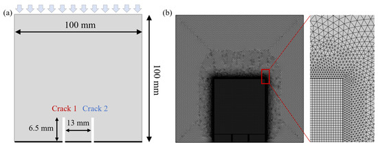
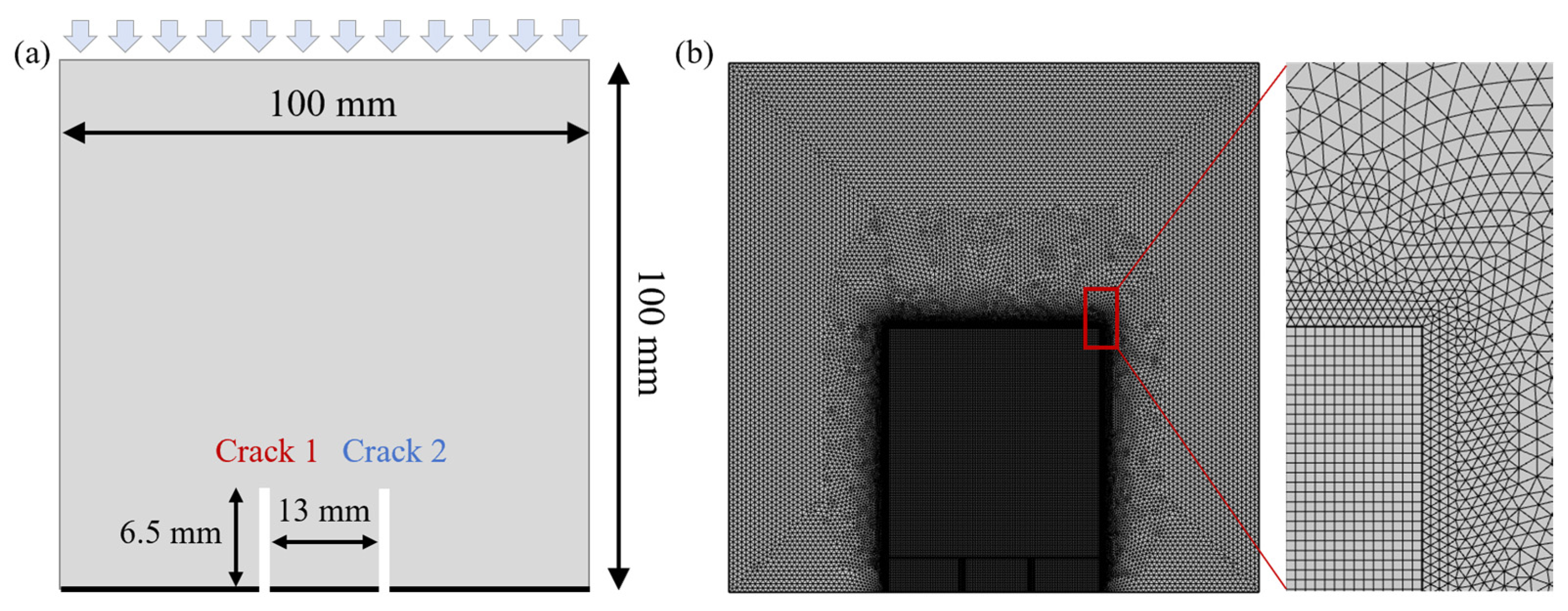
As shown in Figure 1a, the model has a height of 100 mm and a width of 100 mm. Two vertical flaws with an upward length of 6.5 mm are located at the center of the bottom edge, and the spacing between the two flaws is 13 mm. The mechanical boundary conditions are specified as follows: a “fixed point and roller support” is applied at the bottom to eliminate rigid-body motion, and a uniaxial load is imposed on the top boundary. The seepage boundary conditions are that the bottom boundary is set as impermeable, and the fluid pressure on the top and the two side boundaries is prescribed as zero. Fluid is injected into both pre-existing cracks at a constant rate .
Figure 1.
(a) Schematic of the specimen geometry and boundary conditions and (b) illustration of the mesh configuration.
In the numerical simulations, the internal length scale parameter is set to , and the interface phase-field length parameter is taken as . For mesh discretization, Lagrange linear elements are used to discretize the interface phase field over the entire computational domain when assigning spatially varying material properties of mineral grains. Along mineral boundaries, the maximum edge length of the free triangular mesh is constrained to be no larger than . A multiscale meshing strategy is adopted: the mesh is locally refined within the potential crack propagation zone, as shown in Figure 1b. In the refined region, a mapped mesh with an edge length of is used, whereas the remaining region is discretized using the “extremely fine” free triangular mesh preset in COMSOL Multiphysics 6.0.
The initial time step is set to , with a step growth factor of 1.5, and the maximum time step is limited to 0.1 s. The simulation is terminated when the injection time reaches 50 s, or when the propagating crack reaches the boundary of the refined meshing region during loading.
3.2. Design of Numerical Experiments
This study constructs a series of numerical models with different mineral distributions. While keeping the mineral fractions and mean grain size constant, we investigate the mutual interactions of hydraulically induced crack propagation. In addition, a homogeneous model is established for comparison.
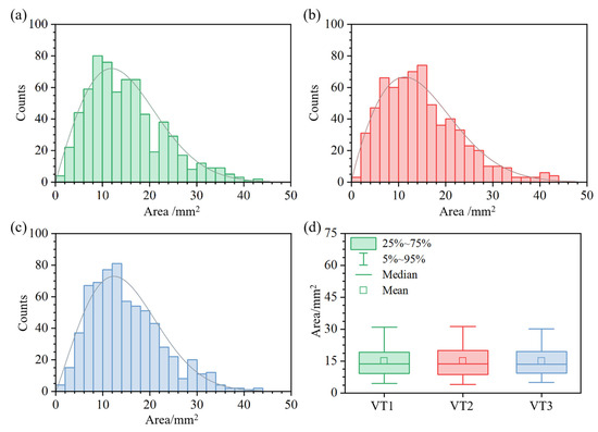
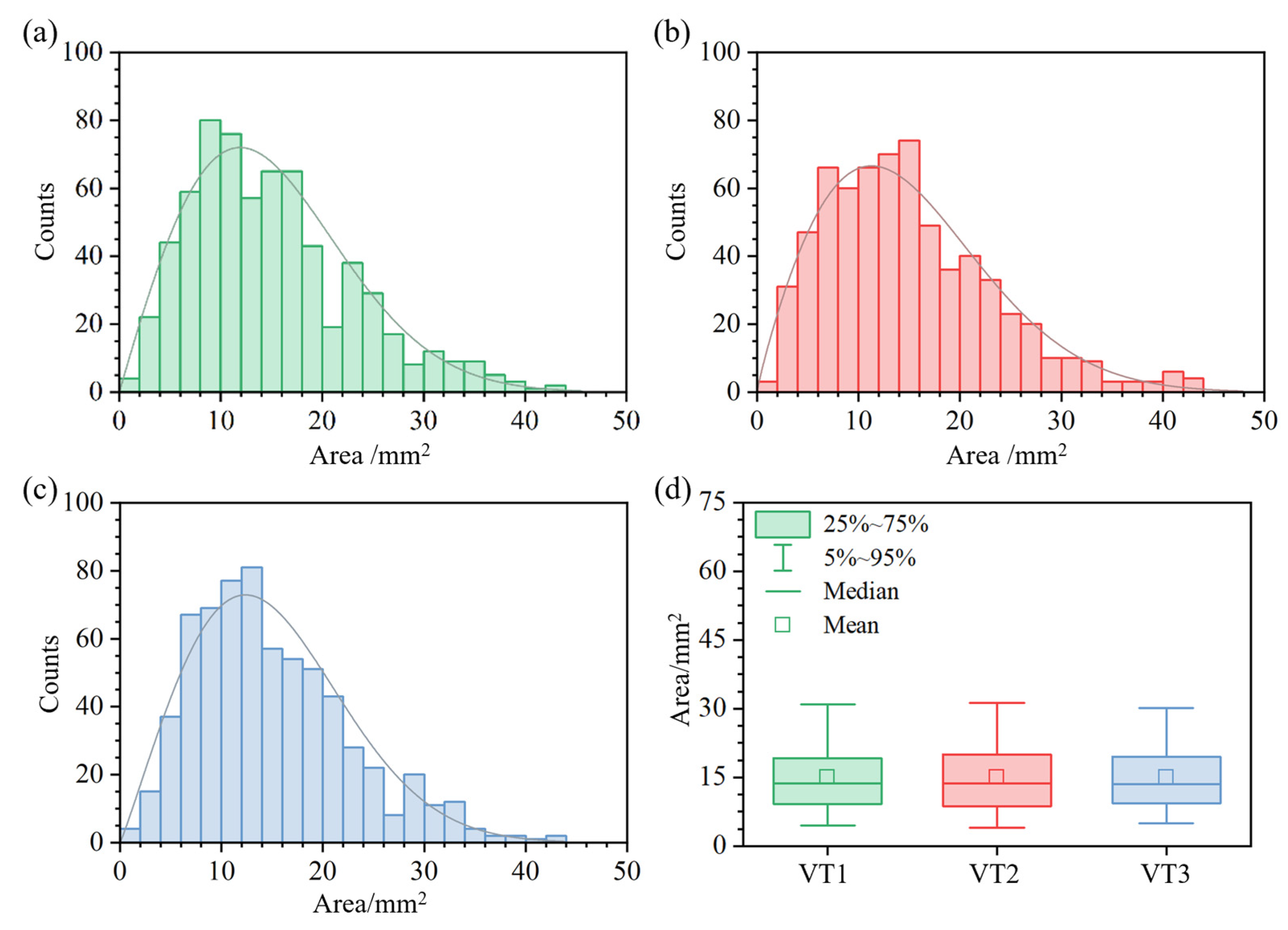
First, based on the area of the computational domain, the mean grain area is controlled at 15 mm2 (corresponding to a total of 667 grains). Using the Neper (version 4.10.1) and varying the random seed, three different Voronoi tessellation (VT) meshes are generated. As indicated by the area distribution histograms in Figure 2, the grain areas in the three model groups are well described by a Weibull distribution, and their statistical characteristics are highly consistent across groups.
Figure 2.
Grain–area distributions for different Voronoi tessellations: (a) VT1, (b) VT2, (c) VT3, and (d) box plot of grain area.
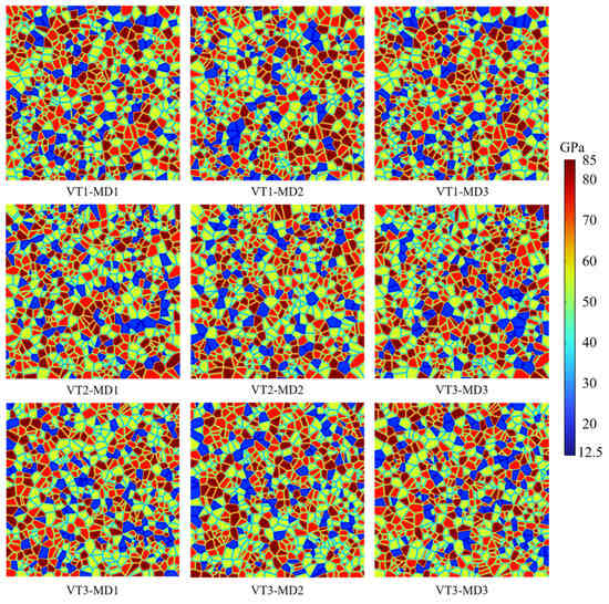
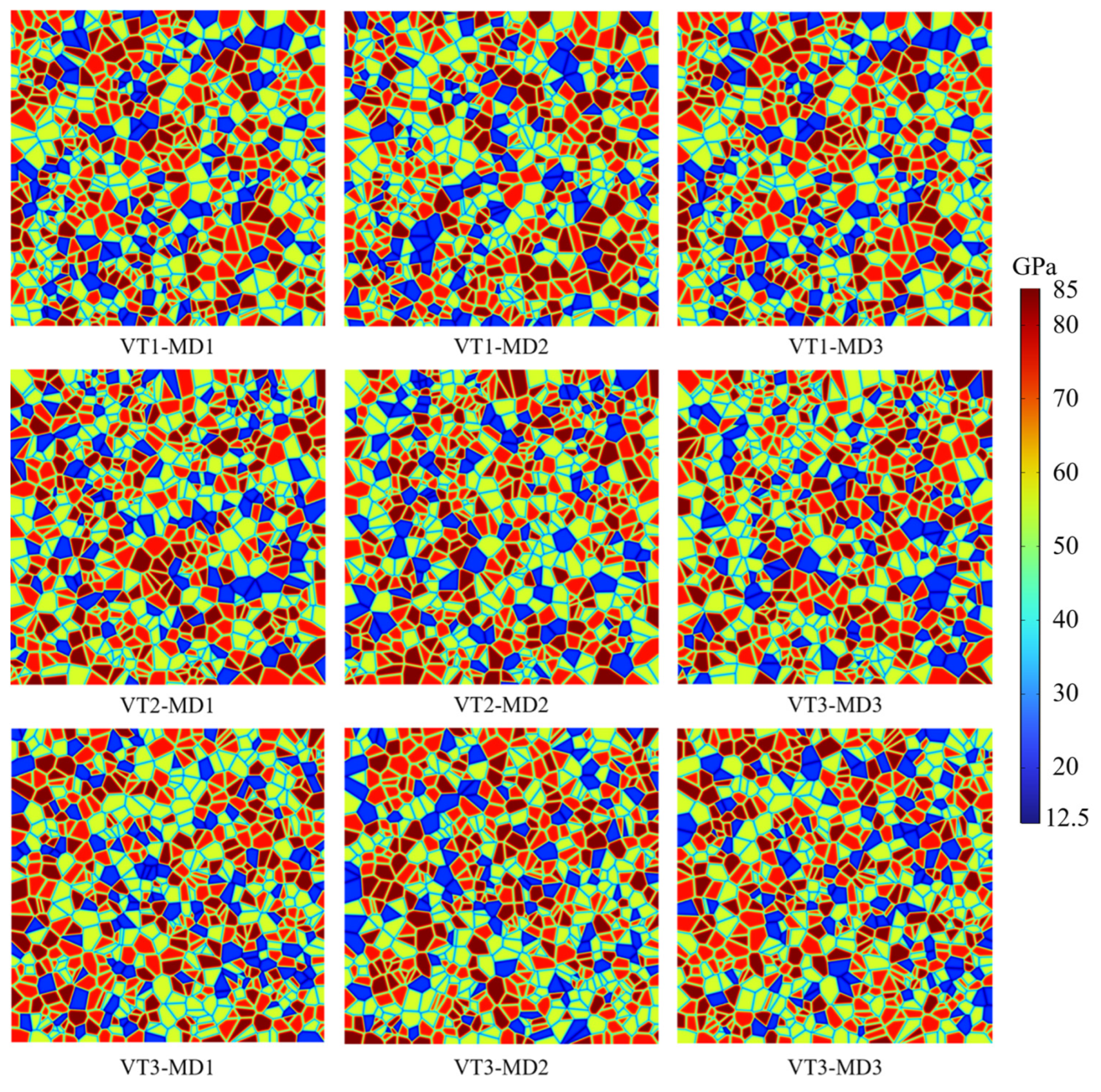
Then, for each generated VT mesh, three different mineral distributions (MDs) are created by randomly permuting the IDs of the Voronoi polygons. After importing the meshes into COMSOL and assigning the corresponding material properties, the resulting spatial distributions of elastic modulus are obtained, as shown in Figure 3. Simulations are performed under two axial loading levels, of 0 MPa and 10 MPa, to enable comparative analyses across all models.
Figure 3.
Spatial distribution of elastic modulus for different mineral distributions under different Voronoi tessellations.
All numerical simulations were conducted in COMSOL Multiphysics. The material heterogeneity is realized through a material-parameter mapping approach. Specifically, the material parameters are solved in Component 1 and then mapped to Component 2 using the General Extrusion Operator. This approach allows greater flexibility in the implementation of boundary conditions and improves the robustness of the numerical model. The Helmholtz equation module solves Equation (17) for the interfacial phase field, from which the material parameters are derived, but it does not participate in the multi-field coupled iterative solution of phase field evolution. The Poisson equation module solves the phase field evolution equation in Equation (8).
3.3. Numerical Implementation and Validation
The hydro-mechanical phase-field model involves solving multiple variables, including displacement, the phase field, and pressure. To ensure numerical stability and improve computational efficiency in the multi-physics coupling, the solution procedure is divided into three stages. The first stage computes heterogeneous material properties based on the Voronoi microstructure. This stage uses the Helmholtz-equation interface to solve the interface phase field equation. The second stage obtains a steady state solution under different axial stresses, which is then used as the initial condition for fluid injection into the pre-existing cracks. The third stage corresponds to the most computationally intensive calculations, solving the coupled evolution of fluid injection and hydraulically induced crack growth.
For the coupled solution, an alternate minimization algorithm is employed. Specifically, the displacement and pore pressure are first solved iteratively using the automatic Newton method, after which the history field is updated. The phase field is then solved using the automatic Newton method, and the above steps are repeated until convergence. In the solver settings, a second-order backward differentiation formula is selected together with Anderson acceleration.
The model is validated against a single-edge notched plate shear test. More details on the numerical implementation and model verification can be found in our previous work [52].
3.4. Material Parameters
To investigate fracture interaction under different grain distributions, all models use the same mineral types and volume fractions: quartz 25%, albite 30%, K-feldspar 30%, and biotite 15%. The fluid parameters are listed in Table 1. The parameters of each mineral are taken from nanoindentation tests [58] and the mechanical parameter table reported by Li et al. [59]. See Table 2.
Table 1.
Fluid-related parameter values used in the model.
Table 2.
Mechanical parameters of different minerals in crystalline rock.
4. Results
Hydraulic fracturing from two initially parallel cracks exhibits non-planar propagation, which is generally regarded as a relatively complex fracture growth behavior. Accordingly, we conduct numerical experiments with different mineral distributions to further elucidate how grain-scale heterogeneity controls the patterns and mechanisms of complex hydraulically induced fracture propagation.
4.1. Crack Propagation Process
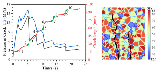
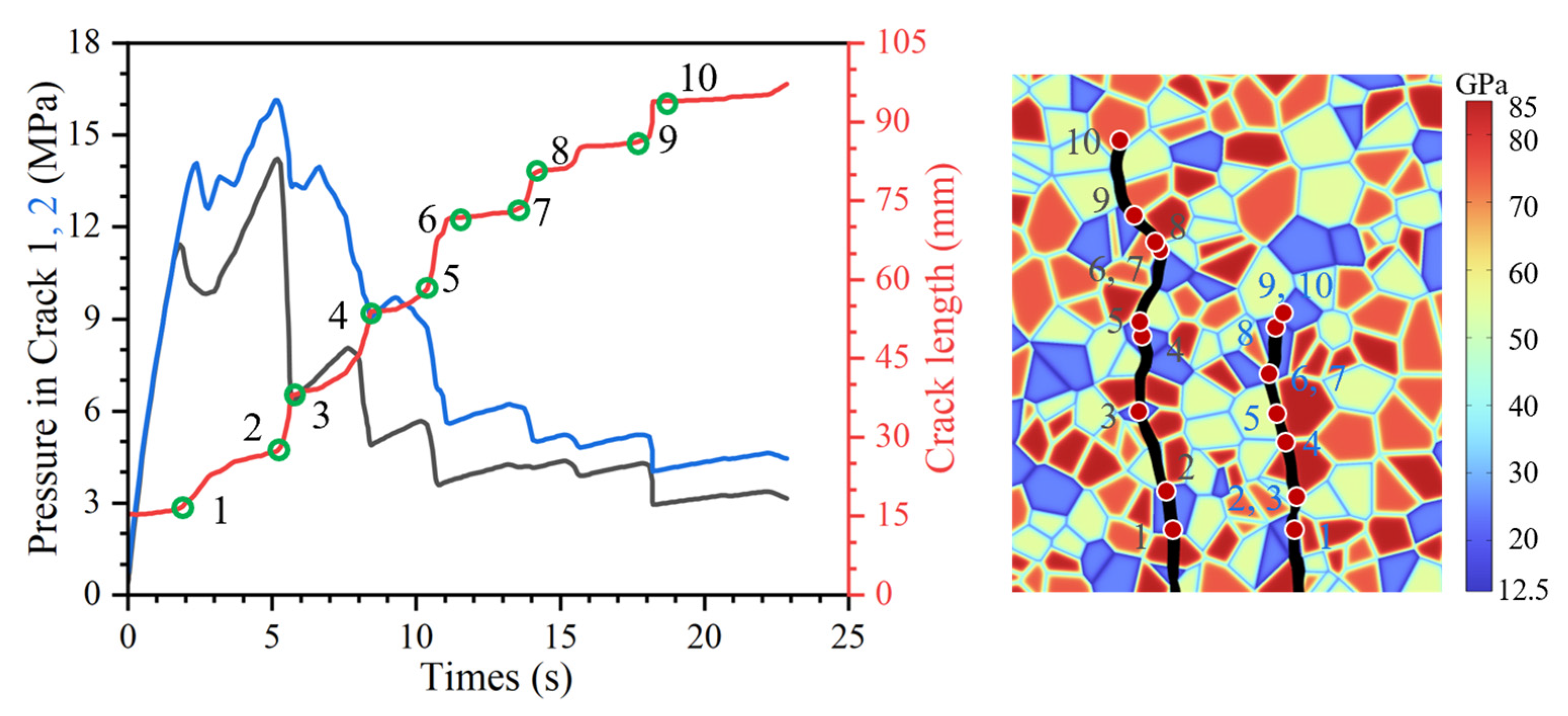
Since crystalline rocks have extremely low permeability, the two pre-existing cracks are not hydraulically connected; therefore, pressure interaction through matrix seepage can be neglected. The pressure evolution within each pre-existing crack is still governed primarily by the local mineral distribution near the propagating fracture front. Taking VT1-MD1 under an axial stress of 10 MPa as an example, the fracture propagation process is shown in Figure 4. The gray curve denotes the pressure in crack 1, and the blue curve denotes the pressure in crack 2.
Figure 4.
Hydraulic fracture propagation process and time histories of pressure and crack length with the evolving fracture path.
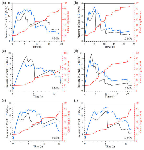
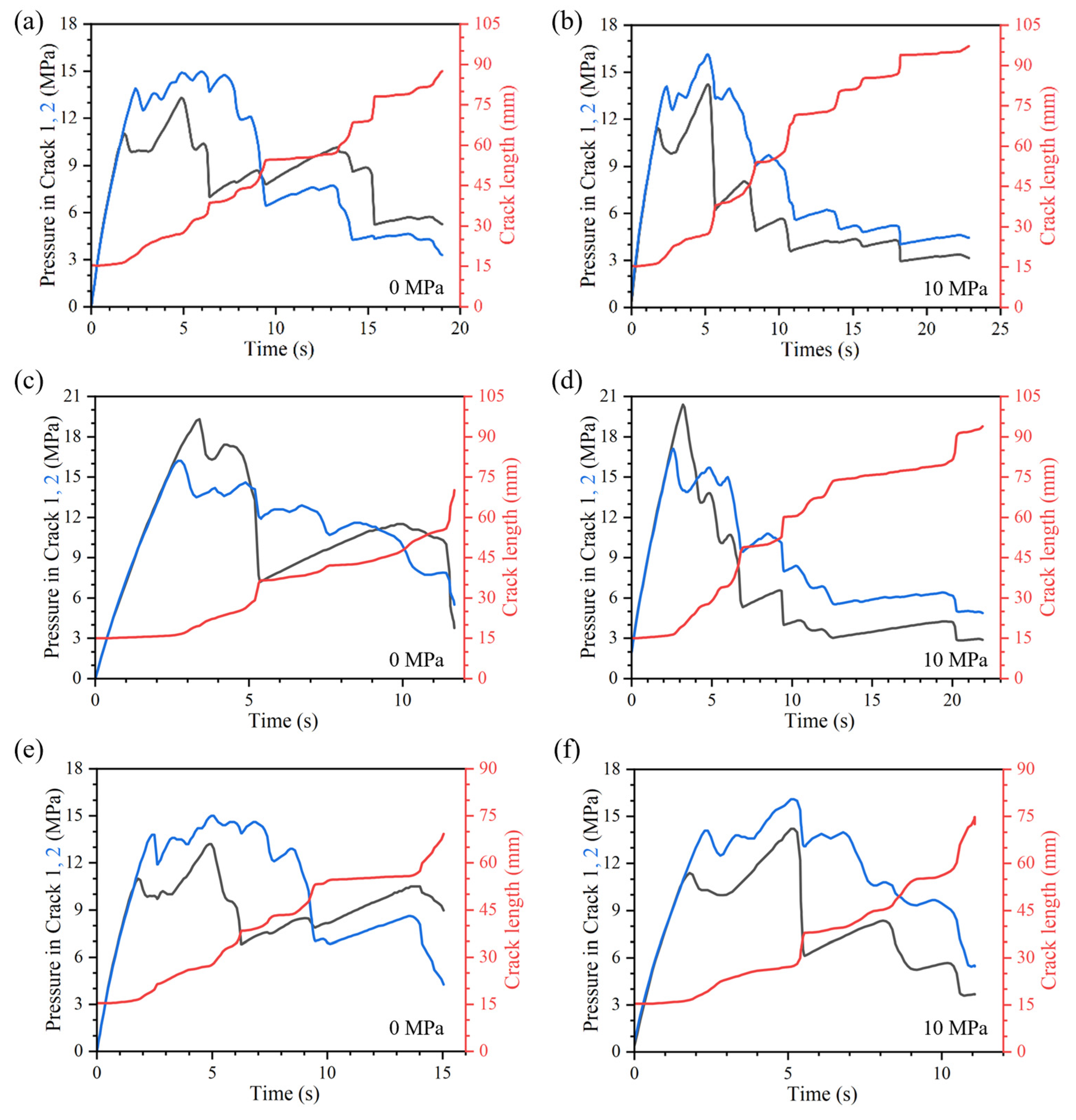
The crack length is obtained by integrating the phase field variable over the entire computational domain according to Equation (2), and thus represents the total crack length of the specimen. It should be noted that the reported crack length is the sum of the two cracks. As a result, the pressure-crack length correspondence is not as clean as in the single crack case, where the pressure curve reaches a local peak while the crack length curve exhibits a clear turning point. Even so, the overall trend remains consistent, pressure build-up and subsequent release are generally accompanied by stepwise increases in the total crack length.
By jointly examining the pressure curves, the crack length evolution, and the final fracture patterns, the staged fluctuations in the responses of the two cracks mainly originate from mesoscopic heterogeneity. During propagation, cracks commonly bypass high-strength minerals and preferentially advance along weak grain boundaries. Fracture growth is highly sensitive to mineral distribution. When a crack propagates through different minerals or along different mineral boundaries, the local resistance to advance can vary markedly, leading to pressure oscillations of different magnitudes and a stepwise increase in the crack length curve.
Specifically, when a crack penetrates from a weaker mineral into a stronger mineral and develops a transgranular crack, the crack tip is typically impeded, and the growth rate decreases. For crack 2, points 2 and 3 almost overlap, indicating stagnation or only a negligible advance during this stage. Meanwhile, the pressure within crack 2 continues to accumulate and reaches its peak between points 3 and 4. Once this peak is reached, the pressure drops rapidly, accompanied by a sudden crack extension to point 4. Similarly, when a crack encounters a high-strength mineral and undergoes a large deflection to detour along grain boundaries, local impediment coupled with pressure build-up can also be observed. An example is provided by points 6 and 7 of crack 1, where the pressure locally rises while crack advance remains slow.
Overall, when the pressure in crack 1 or crack 2 reaches an extreme value and is then rapidly released, the corresponding crack often exhibits rapid propagation, and the crack length increases substantially over a short period. In contrast, when the pressures in both cracks are in a gradual accumulation stage, crack propagation is generally slow and may even experience brief arrest. This coupled evolution indicates that heterogeneous microstructures, by modulating the local resistance near the crack tip, dominate both the pressure fluctuations and the stepwise crack length growth.
This behavior can be interpreted from the principle of minimum energy. The fracture path is essentially controlled by the energy required for further advance. Under a given set of external constraints and injection conditions, the system tends to evolve along the direction that minimizes the incremental increase in total energy. Therefore, when the crack must penetrate a high-strength grain to form a transgranular fracture, or undergoes a large deflection to bypass such grains, the associated fracture work and dissipation increase significantly. At this stage, the available energy is insufficient to immediately satisfy the propagation condition, and the crack becomes impeded, slows down, or temporarily arrests. Meanwhile, continued fluid injection progressively accumulates fluid potential energy and elastic strain energy, manifested macroscopically as a sustained local rise in pressure. Once the accumulated energy finally reaches and slightly exceeds the required energy threshold, the system releases energy rapidly along the optimal energy-descent path, resulting in a sharp pressure drop accompanied by a burst-like crack advance.
4.2. Crack Propagation Path
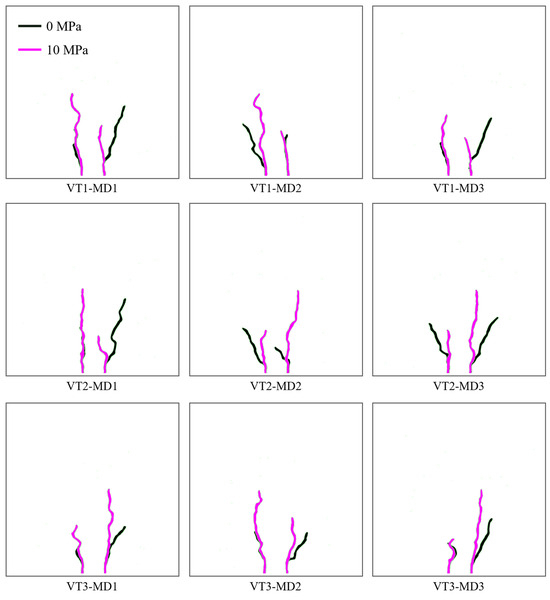
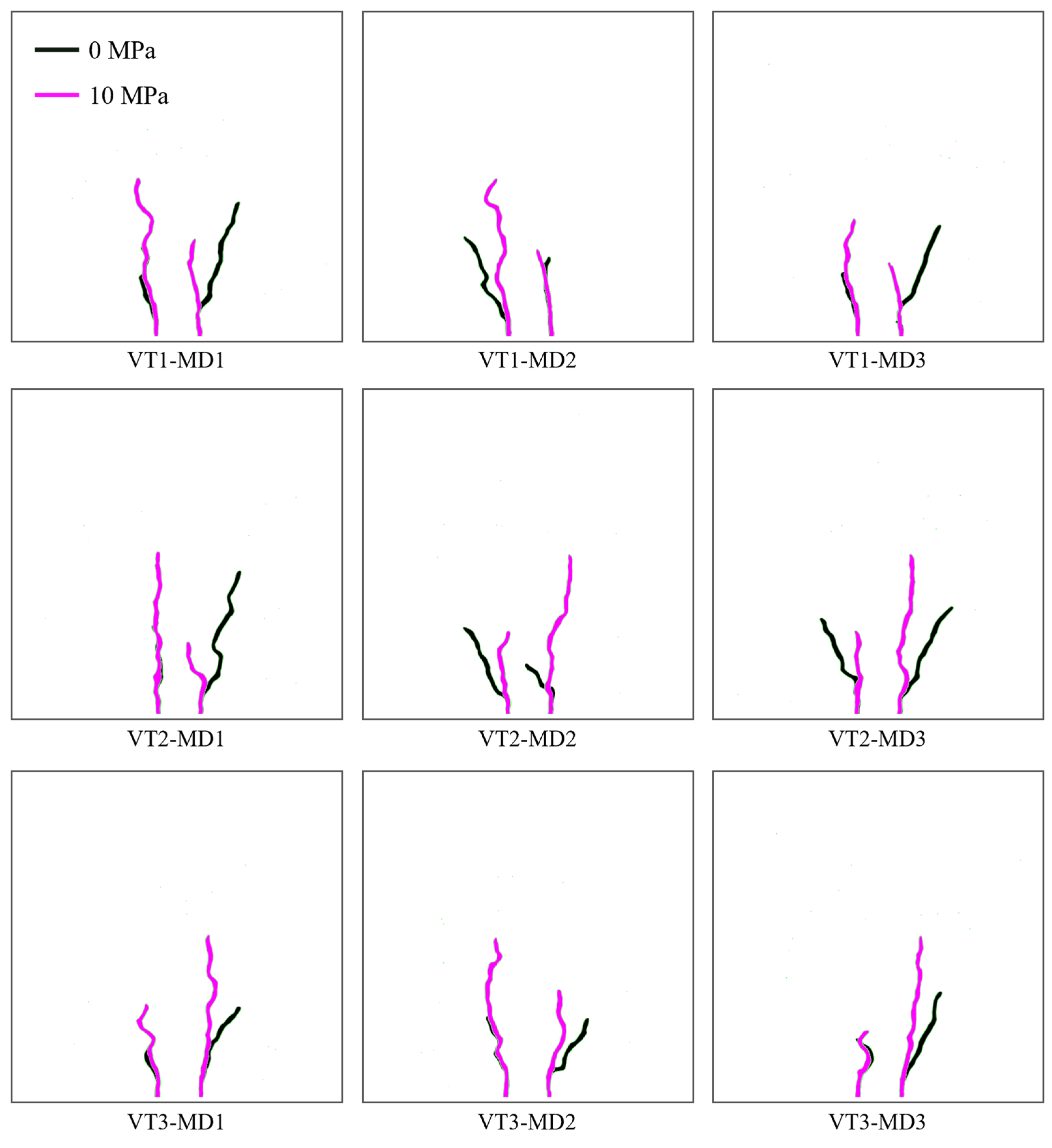
Figure 5 shows the fracture propagation paths under different mineral distributions. Consistent with the results in Figure 4, the path selection generally follows a minimum-energy principle. Fractures tend to bypass high-strength minerals and preferentially propagate through weaker grains and along weak interfaces. Rearranging the grain-scale mineral distribution alters the spatial pattern of effective material properties at the specimen scale, thereby changing the energetically preferred propagation route. Consequently, even on the same Voronoi tessellation mesh, changing only the mineral distribution can lead to pronounced differences in fracture trajectories.
Figure 5.
Crack propagation paths for models with different mineral distributions.
In addition, the two cracks exhibit markedly different extents of growth. One crack propagates more extensively and reaches a substantially greater length, whereas the other remains comparatively limited. As indicated by the propagation process in Figure 4 and Figure 5, once one crack initiates significant growth earlier, the subsequent propagation of the other crack is often suppressed. This is because crack growth redistributes the local stress and strain energy fields, which in turn diminishes the driving force at the tip of the competing crack, making the conditions required for its continued advance more difficult to satisfy.
Beyond the dominant role of mineral distribution, axial compression also exerts a clear control on the overall path morphology. Across the three Voronoi tessellations, it is observed that under an axial stress of 0 MPa, the cracks tend to spread outward toward the left and right sides of the model, exhibiting a more laterally dispersed propagation pattern, whereas under 10 MPa, they propagate preferentially in a more vertically oriented direction. Because the propagation paths change substantially with axial stress, even for the same mineral distribution, the pressure and crack length evolution curves can differ significantly between the two loading levels, as shown in Figure 6.
Figure 6.
Evolution of pressure and crack length with injection time for VT1 under different MDs: (a,b) MD1, (c,d) MD2, and (e,f) MD3.
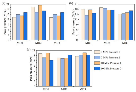
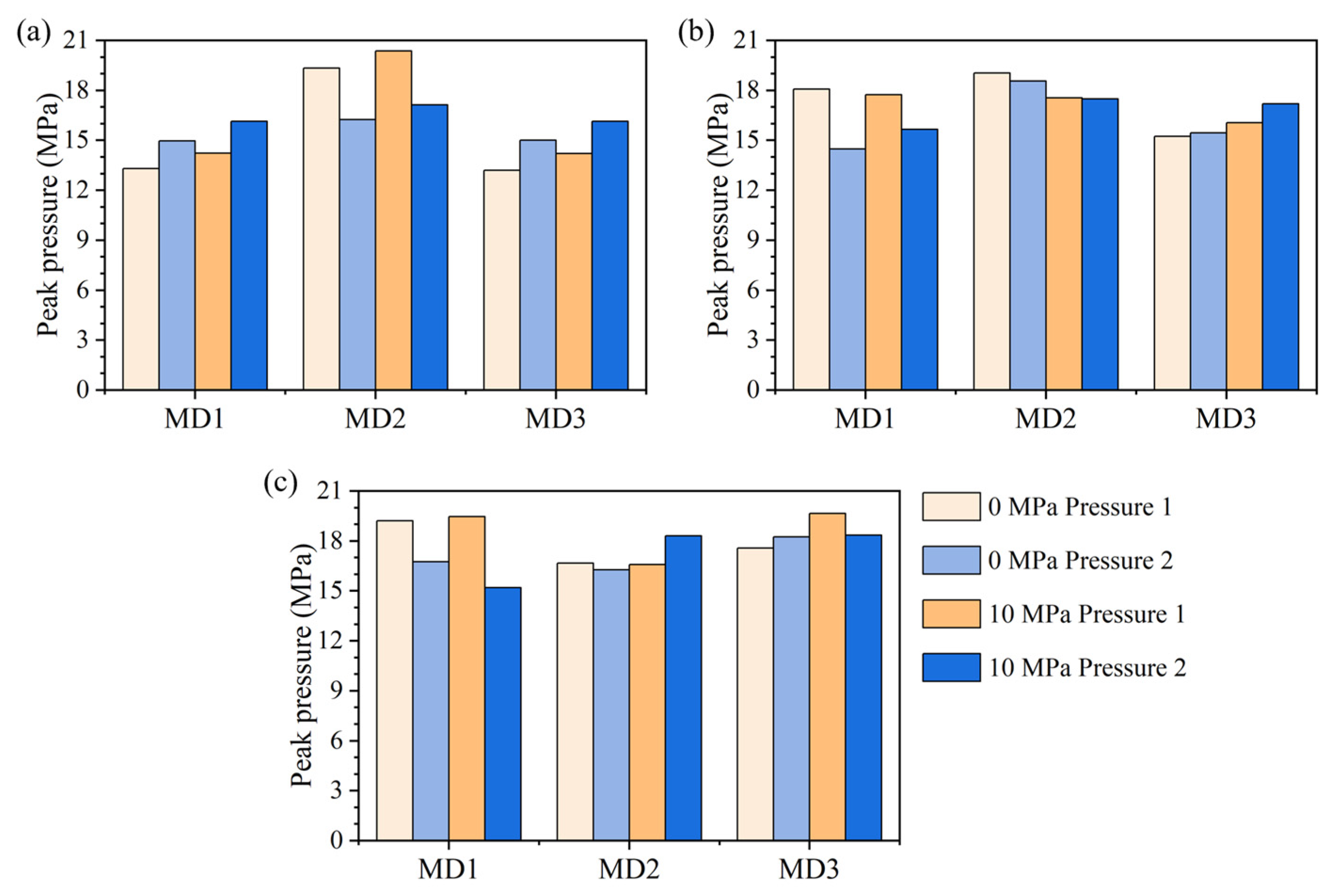
The peak injection pressures for the three Voronoi tessellations are summarized in Figure 7. Since each specimen contains two pre-existing cracks, the peak pressures corresponding to crack 1 and crack 2 were analyzed separately for the nine mineral distribution groups under two axial stress levels.
Figure 7.
Peak injection pressure under different MDs: (a) VT1, (b) VT2, and (c) VT3.
For crack 1, the mean peak pressure is 16.85 MPa with a standard deviation of 2.43 MPa under 0 MPa axial stress, and 17.32 MPa with a standard deviation of 2.26 MPa under 10 MPa axial stress. For crack 2, the mean peak pressure is 16.22 MPa with a standard deviation of 1.43 MPa under 0 MPa axial stress, and 16.85 MPa with a standard deviation of 1.13 MPa under 10 MPa axial stress. Paired-sample t-tests further show that the differences between the two axial stress levels are not statistically significant for either crack 1 (p = 0.211) or crack 2 (p = 0.166). These results indicate that, although axial compression significantly changes the evolution trends of the pressure and crack growth curves, its effect on peak injection pressure is statistically insignificant and relatively limited within the investigated range. In contrast, the peak pressure scatter among specimens with different mineral distributions is much more evident and pronounced in Figure 7, confirming that mineral distribution remains the dominant controlling factor for peak injection pressure.
4.3. Influence of Local Heterogeneity on Crack Paths
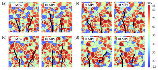
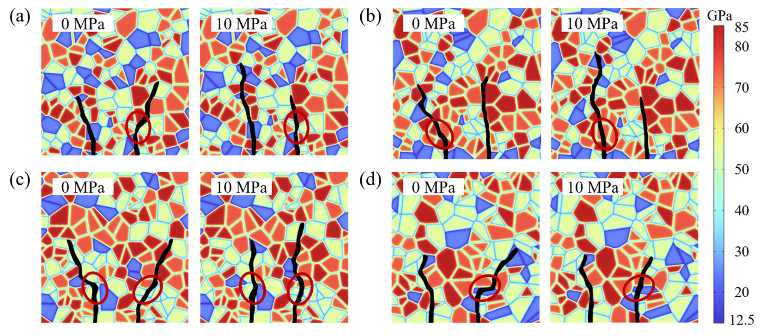
As discussed in the previous section, the crack propagation path varies significantly under different axial pressures. Specifically, at 0 MPa axial pressure, cracks tend to propagate laterally toward the left or right boundaries of the model. Conversely, at 10 MPa, cracks tend to propagate vertically. This phenomenon is analyzed in detail with reference to the early stages of crack propagation shown in Figure 8, where regions exhibiting different crack propagation directions are enclosed in red boxes.
Figure 8.
Distinct crack path selections under different axial pressures: (a) VT1-MD1, (b) VT1-MD2, (c) VT2-MD3, and (d) VT3-MD2.
In Figure 8a, crack 2 under 0 MPa follows the lower boundary of quartz and extends toward the right model boundary, while under 10 MPa, it propagates vertically along the interface between two quartz grains. In Figure 8b, under 0 MPa, crack 1 propagates along the boundary between quartz and albite toward the left model boundary. Under 10 MPa, however, it penetrates the albite grain, forming a more vertically oriented transgranular crack. Figure 8c shows that under 0 MPa, crack 1 extends along the weaker boundary between biotite and K-feldspar toward the left, while crack 2 propagates upward along the boundary between albite and K-feldspar. Under 10 MPa, crack 1 extends upward along a near-vertical interface between K-feldspar and albite, and crack 2 forms a transgranular crack through albite. Similarly, in Figure 8d, under 0 MPa, crack 2 extends along the boundary between albite and biotite toward the right boundary, whereas under 10 MPa, it penetrates the albite grain, forming a vertical transgranular crack. These early-stage path selections ultimately lead to markedly different overall crack trajectories under different axial stresses.
A plausible explanation for this phenomenon is that a high axial pressure enhances the guidance of the principal stress direction on crack propagation, favoring paths aligned with the maximum principal stress. This can also be interpreted from an energy perspective. Under 10 MPa axial pressure, the original crack path is no longer energetically favorable. Propagation along it would result in a higher elastic free energy of the system. Consequently, under high axial pressure, cracks tend to propagate vertically. It is noteworthy that regardless of the axial pressure, the inherent heterogeneity of the system, particularly the morphology of grain boundaries and the distribution of mineral grains, continues to play a decisive role in crack propagation.
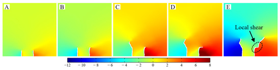
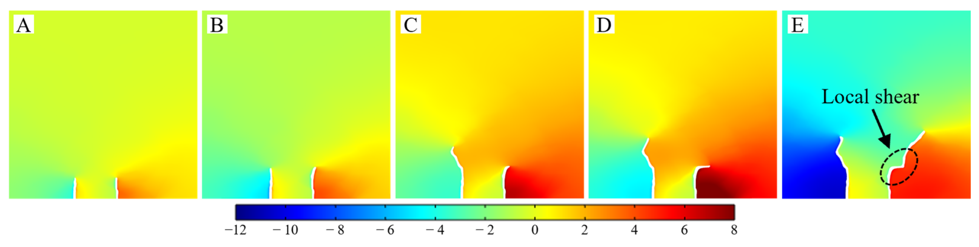
To analyze the phenomenon of cracks propagating toward the lateral boundaries under low axial pressure, Figure 9 illustrates the case of VT3-MD2 at 0 MPa. The time-lapse evolution of the horizontal displacement field reveals a pronounced relative offset across the marked fracture surfaces, indicating a significant shear component in the local failure mode.
Figure 9.
Horizontal displacement field of VT3-MD2 under an axial stress of 0 MPa. The corresponding time points (A–E) are indicated in Figure 10.
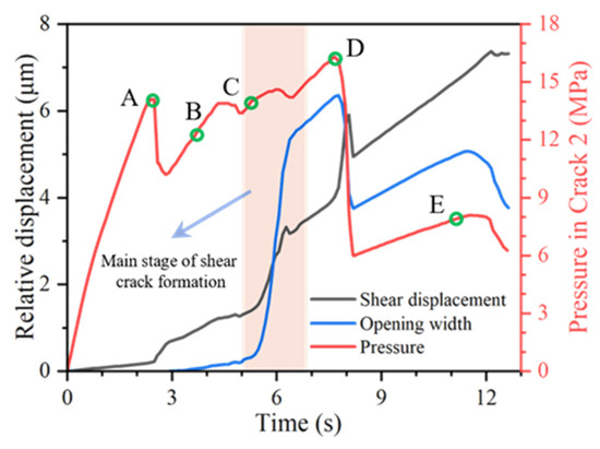
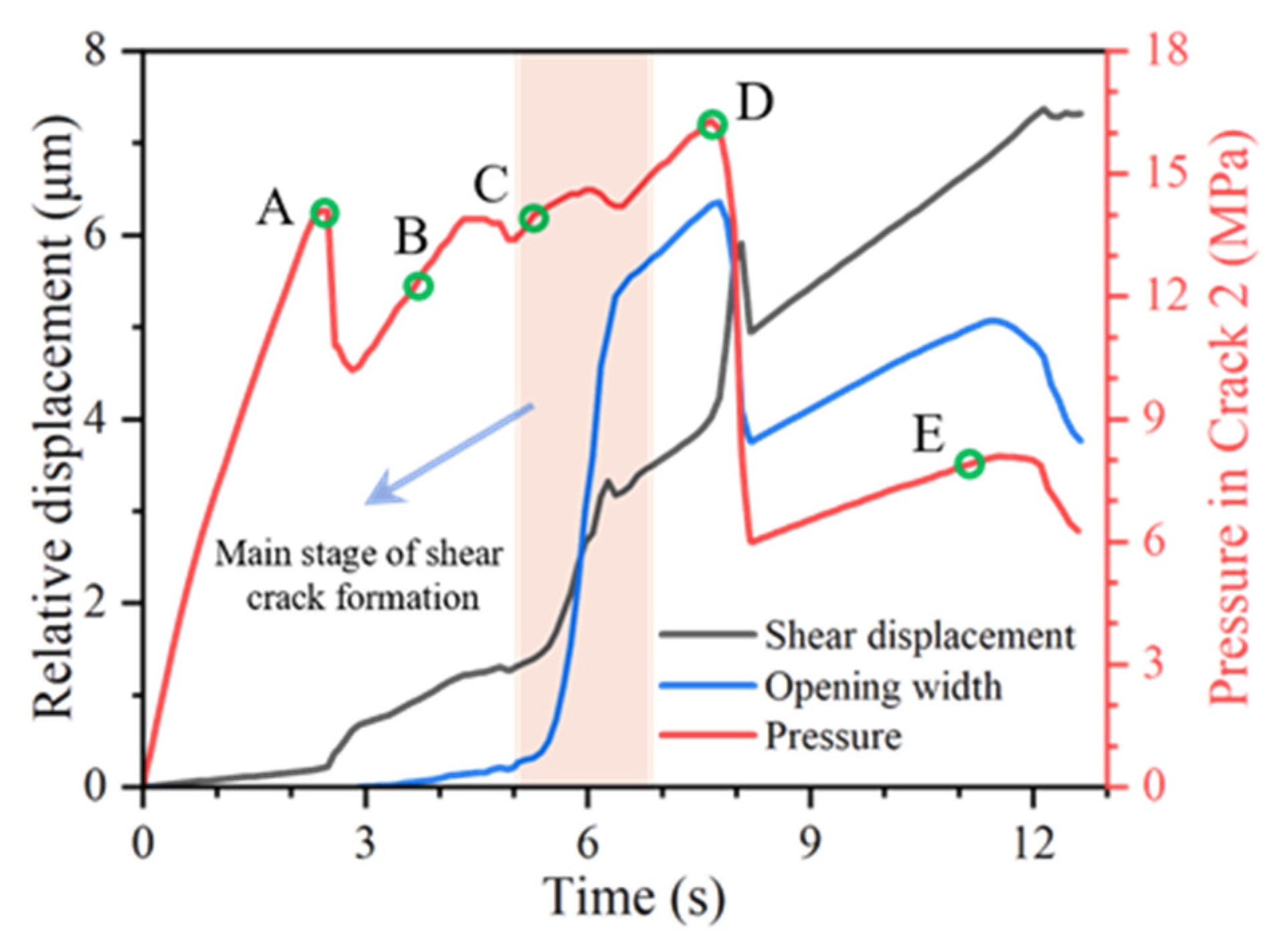
Figure 10 presents the evolution of relative shear displacement and opening width across the fracture. During the shaded time interval, this local shear-dominated crack gradually develops, and the opening width continues to increase while the relative shear displacement accumulates simultaneously. These results indicate that hydraulically induced fractures may exhibit locally shear-dominated rupture, and the occurrence of such behavior is closely associated with weak planes adjacent to mineral grains that obstruct the main fracture path. Because this weak plane is nearly perpendicular to the primary propagation direction, the crack tip is locally prone to shear slip along grain boundaries, promoting the formation of intergranular cracks.
Figure 10.
Evolutions of shear displacement and opening width of the local shear crack.
5. Discussion
To validate the universality of the fracture mechanisms observed in heterogeneous rock, we further investigated the crack evolution in a homogeneous model, as shown in Figure 11. This homogeneous model is an idealized case, assuming isotropic material properties and is not intended to represent any specific natural rock. In reality, rocks inevitably exhibit some degree of heterogeneity; therefore, the homogeneous case used here serves only as a reference to help clarify the role of heterogeneity in fracture development.
Figure 11.
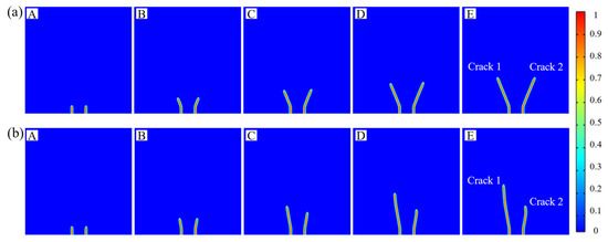
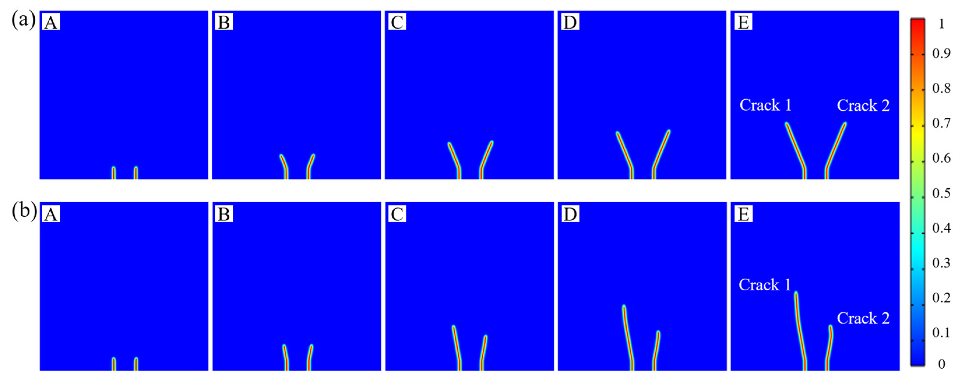
Phase field evolution in the homogeneous model: (a) axial stress 0 MPa and (b) axial stress 10 MPa. The corresponding time points (A–E) are indicated in Figure 12.
In the homogeneous case, the two cracks propagate symmetrically under an axial stress of 0 MPa. When the axial stress increases to 10 MPa, the two propagation paths gradually become asymmetric and evolve toward a more vertically oriented growth direction. This reiterates that the vertical axial compression at 10 MPa provides a clearer principal-stress guidance, such that the energetically most favorable propagation route becomes more vertical.
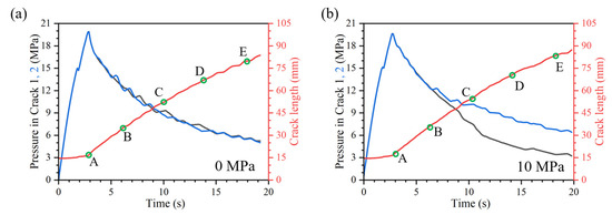
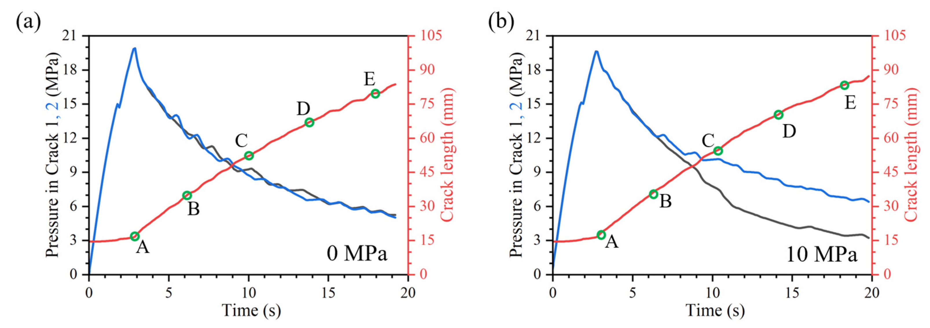
The evolutions of injection pressure and crack length in the homogeneous model under the two axial-stress levels are shown in Figure 12. Under 0 MPa axial stress, the pressure-time curves in the two cracks almost completely overlap, and the fractures grow to essentially the same extent. Under 10 MPa axial stress, the pressure curves in the two cracks also largely coincide before time B; however, after time B, the pressure in crack 1 is released earlier and remains at a lower level, while its crack length becomes larger, indicating a stronger propagation advantage. This confirms a fundamental mechanism: the crack that successfully releases hydraulic pressure first establishes a propagation advantage, thereby suppressing the growth of adjacent cracks. Under 0 MPa axial stress, the two cracks exhibit nearly overlapping pressure profiles and equivalent propagation scales. However, imposing a 10 MPa axial stress triggers a competitive behavior. Although the pressure curves coincide initially, they diverge after time B. Crack 1 undergoes an earlier pressure drop and sustains a higher growth rate, demonstrating a superior propagation advantage. This phenomenon validates a key mechanical principle: the crack that first successfully dissipates hydraulic pressure secures a propagation priority.
Figure 12.
Pressure and crack length evolution with injection time in the homogeneous model: (a) axial stress 0 MPa and (b) axial stress 10 MPa.
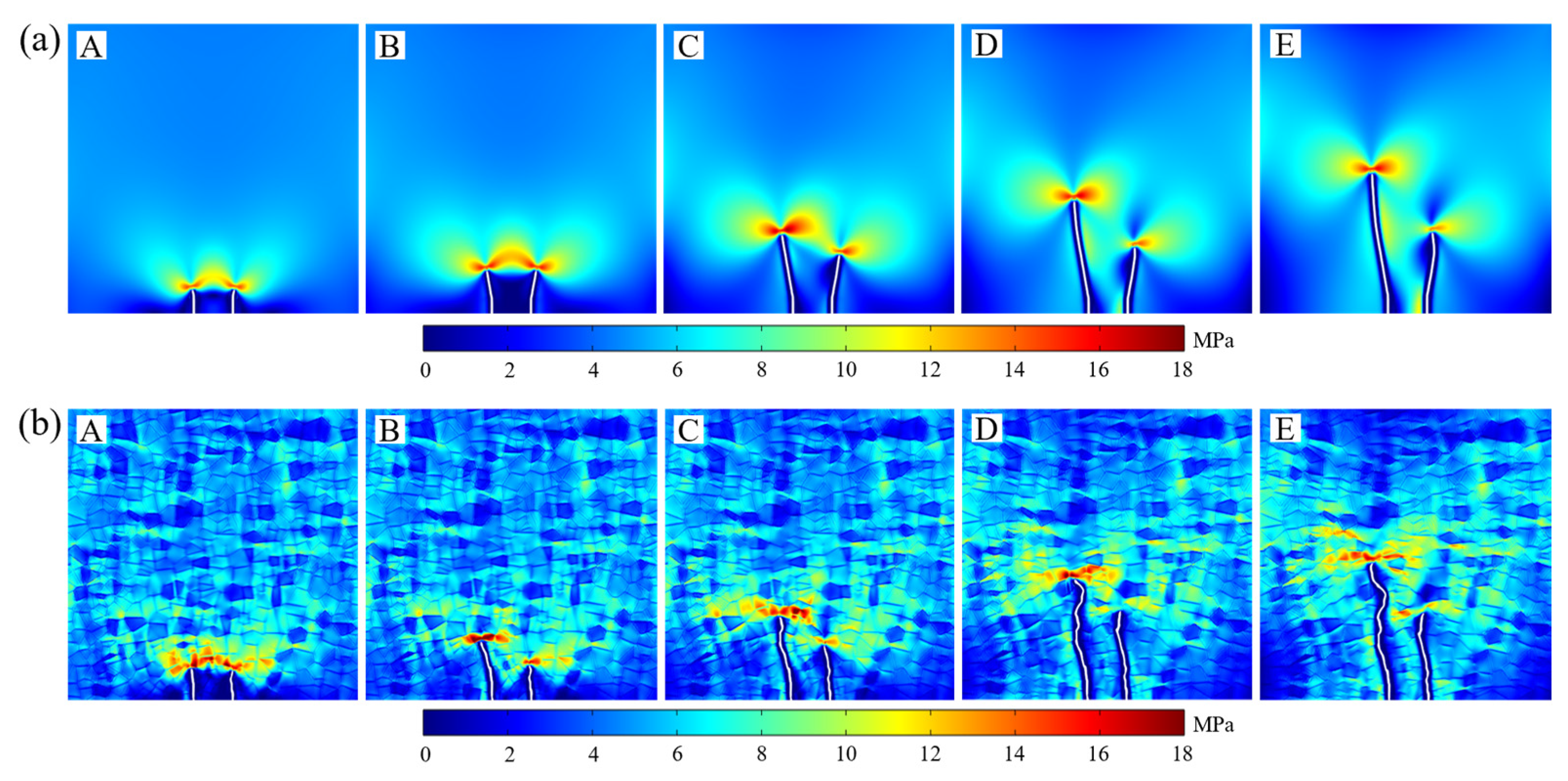
To explain the inconsistent propagation of the two cracks in the homogeneous model under the 10 MPa condition, Figure 13a presents the distributions of the maximum principal stress at different time steps. It can be observed that a relatively high concentration of is consistently maintained ahead of the tip of the dominant crack, whereas a distinct region of low appears ahead of the tip of the lagging crack, indicating that the former exerts a stress-shielding effect on the latter. During the initial stage of crack propagation, the two cracks propagate to a similar extent. However, due to slight differences in the initial mesh discretization, subtle discrepancies arise in the stress fields ahead of the two crack tips after time B. These small differences subsequently lead to unequal crack propagation, which in turn induces stress shielding, causing the disparity in crack growth between the two cracks to progressively increase.
Figure 13.
Evolution of the maximum principal stress () distribution at 10 MPa: (a) homogeneous model and (b) VT1-MD1. The corresponding time points (A–E) are indicated in Figure 12.
This phenomenon becomes more pronounced in the heterogeneous model. Taking VT1-MD1 as an example, Figure 13b shows the distributions of at different stages of crack propagation in the heterogeneous model. Owing to the heterogeneity of the rock, a clear difference in the stress fields at the two crack tips emerges even at the early stage of crack propagation. As a result, crack 1, which is located in a weaker grain, propagates preferentially and produces a significant stress-shielding effect on crack 2.
In addition, the overall trends show that, in the homogeneous model, both the pressure and crack-length curves vary more smoothly with injection time, and the crack length increases in a sustained and stable manner. The stepwise growth observed in heterogeneous models does not occur here, further highlighting the pronounced influence of heterogeneity on crack growth processes and evolution characteristics.
6. Conclusions
This study employs a hydro-mechanical phase-field model with Voronoi-based microstructures to simulate hydraulic fracturing from two parallel pre-existing cracks in crystalline rock. By varying mineral distribution and axial stress levels, we analyze how heterogeneity controls injection pressure evolution, crack length growth, and fracture-path selection. The main conclusions are as follows:
- (1)
- Mineral distribution is the primary control on complex non-planar fracture growth. Even under an identical Voronoi tessellation, redistributing minerals leads to substantial differences in trajectories, branching, deflection, and final morphology.
- (2)
- Non-planar growth follows a stepwise, energy-threshold-driven mechanism. When fractures encounter strong grains or require large deflections, propagation is impeded, and pressure builds up. Once the accumulated energy reaches a critical threshold, rapid energy release occurs along the minimum incremental energy path, resulting in sharp pressure drops and crack advances.
- (3)
- Strong mechanical competition exists between the two fractures. Although hydraulic interference is negligible in low-permeability crystalline rock, early growth of one crack redistributes stresses and suppresses the other, leading to asymmetric propagation where one crack dominates.
- (4)
- Axial compression primarily influences the overall propagation orientation and local failure mode but has a limited impact on peak injection pressure. Increasing axial stress promotes vertically oriented trajectories and can induce locally shear-dominated intergranular rupture.
Author Contributions
Conceptualization, G.Z., C.Z. and J.X.; methodology, G.Z., J.X. and Z.T.; software, G.Z. and J.X.; validation, G.Z., C.Z. and J.X.; formal analysis, G.Z.; investigation, G.Z., Z.T., J.N. and W.Y.; resources, C.Z., J.X. and J.N.; data curation, G.Z., J.X. and Z.W.; writing—original draft preparation, G.Z. and Z.T.; writing—review and editing, C.Z., Z.T. and J.X.; visualization, G.Z. and W.Y.; supervision, J.X.; project administration, C.Z. and J.X.; funding acquisition, C.Z. and J.X. All authors have read and agreed to the published version of the manuscript.
Funding
This work was supported by the “Central Government Guides Local Science and Technology Development” Project of Tibet Autonomous Region (Grant No. XZ202401YD0003), the National Natural Science Foundation of China (No. U22A20597, No. 42407227), and the “Key Research and Development Program” Project of Science and Technology Program of Tibet (Grant No. XZ202501ZY0104, XZ202501ZY0132).
Data Availability Statement
The data that support the findings of this study are available from the corresponding author upon reasonable request.
Acknowledgments
The authors thank the team members for providing their computers, which served as crucial computational resources for the numerical simulations in this study.
Conflicts of Interest
The authors declare no conflicts of interest.
References
- Zhao, J.; Ren, L.; Lin, C.; Lin, R.; Hu, D.; Wu, J.; Song, Y.; Shen, C.; Tang, D.; Jiang, H. A review of deep and ultra-deep shale gas fracturing in China: Status and directions. Renew. Sustain. Energy Rev. 2025, 209, 115111. [Google Scholar] [CrossRef] [Scilit]
- Huang, L.; Liao, X.; Fan, M.; Wu, S.; Tan, P.; Yang, L. Experimental and numerical simulation technique for hydraulic fracturing of shale formations. Adv. Geo-Energy Res. 2024, 13, 83–88. [Google Scholar] [CrossRef] [Scilit]
- Li, J.; Tang, S.; Li, T.; Zhang, S.; Tang, L.; Sun, K. Study on rockburst control of deep-buried tunnel by combining advanced stress release borehole and hydraulic fracturing. Tunn. Undergr. Space Technol. 2025, 160, 106517. [Google Scholar] [CrossRef] [Scilit]
- Ren, J.; Su, K.; Sun, C. Hydraulic fracturing pressure-relief technology for controlling the surrounding rock in deep dynamic pressure roadways. Appl. Sci. 2025, 15, 9779. [Google Scholar] [CrossRef] [Scilit]
- Du, B.; Zhang, F.; Zhang, C. Distinct element modeling of hydraulic fracture propagation with discrete fracture network at gonghe enhanced geothermal system site, northwest China. J. Rock Mech. Geotech. Eng. 2025, 17, 3435–3448. [Google Scholar] [CrossRef] [Scilit]
- Zhang, X.; Si, G.; Ji, Y.; Cao, A.; Wang, C. Grain size effects on hydro-seismo-mechanical responses of granite during laboratory hydraulic fracturing. Int. J. Rock Mech. Min. Sci. 2025, 194, 106241. [Google Scholar] [CrossRef] [Scilit]
- Wang, S.; Elsworth, D.; Zhang, L.; Zhao, X.; Wang, T. Hydro-grain-texture modeling of systematics of propagation, branching, and coalescence of fluid-driven fractures. Rock Mech. Rock Eng. 2025, 58, 623–644. [Google Scholar] [CrossRef] [Scilit]
- Yoshioka, K.; Katou, M.; Tamura, K.; Arima, Y.; Ito, Y.; Chen, Y.; Ishida, T. Interactions of hydraulic fractures with grain boundary discontinuities in the near wellbore region. J. Geophys. Res. Solid Earth 2023, 128, e2022JB024509. [Google Scholar] [CrossRef] [Scilit]
- Zhang, C.; Fan, D.; Elsworth, D.; He, M.; Zhao, X.; Zhu, C.; Zhang, H. Mechanisms of stress- and fluid-pressure-driven fault reactivation in gonghe granite: Implications for injection-induced earthquakes. Int. J. Rock Mech. Min. Sci. 2024, 174, 105642. [Google Scholar] [CrossRef] [Scilit]
- Zhang, C.; Xu, J.; Wang, H.; He, M.; Gou, Y.; Chen, Q. Evaluating in-situ stress state and stress heterogeneity by hydraulic fracturing and image logging in changcun coalbed methane area, north China. Rock Mech. Rock Eng. 2025, 58, 1723–1738. [Google Scholar] [CrossRef] [Scilit]
- Jia, Y.; Lu, Z.; Xiong, Q.; Hampton, J.C.; Zhang, Y.; He, P. Laboratory characterization of cyclic hydraulic fracturing for deep shale application in southwest China. Int. J. Rock Mech. Min. Sci. 2021, 148, 104945. [Google Scholar] [CrossRef] [Scilit]
- Zhang, Y.; Zhao, Y.; Zang, A.; Long, A. Acoustic emission evolution and hydraulic fracture morphology of changning shale stressed to failure at different injection rates in the laboratory. Rock Mech. Rock Eng. 2024, 57, 1287–1308. [Google Scholar] [CrossRef] [Scilit]
- Zhao, H.; Liang, B.; Sun, W.; Hu, Z.; Ma, Y.; Liu, Q. Effects of hydrostatic pressure on hydraulic fracturing properties of shale using x-ray computed tomography and acoustic emission. J. Pet. Sci. Eng. 2022, 215, 110725. [Google Scholar] [CrossRef] [Scilit]
- Wei, X.; Cai, M.; Kong, C.; Zhao, D. Spatiotemporal evolution analysis of multiscale fracture dynamics in hydraulic shale stimulation via integrated acoustic emission and ct imaging. Sci. Rep. 2025, 15, 44451. [Google Scholar] [CrossRef] [Scilit]
- Zhao, C.; Xing, J.; Zhou, Y.; Shi, Z.; Wang, G. Experimental investigation on hydraulic fracturing of granite specimens with double flaws based on dic. Eng. Geol. 2020, 267, 105510. [Google Scholar] [CrossRef] [Scilit]
- Zhang, R.; Zhao, C.; Yang, C.; Xing, J.; Morita, C. A comprehensive study of single-flawed granite hydraulically fracturing with laboratory experiments and flat-jointed bonded particle modeling. Comput. Geotech. 2021, 140, 104440. [Google Scholar] [CrossRef] [Scilit]
- Tian, Y.; Zhao, C.; Xing, J.; Niu, J.; Qian, Y. A new digital image correlation method for discontinuous measurement in fracture analysis. Theor. Appl. Fract. Mech. 2024, 130, 104299. [Google Scholar] [CrossRef] [Scilit]
- Dehghan, A.N. An experimental investigation into the influence of pre-existing natural fracture on the behavior and length of propagating hydraulic fracture. Eng. Fract. Mech. 2020, 240, 107330. [Google Scholar] [CrossRef] [Scilit]
- Cheng, L.; Xie, Y.; Luo, Z.; Wu, L. Numerical analysis of 3d nonplanar hydraulic fracture propagation in fractured-vuggy formations using a hydromechanical coupled xfem approach. Comput. Geotech. 2024, 170, 106267. [Google Scholar] [CrossRef] [Scilit]
- Pham, S.T.; Nguyen, B.N.A. Numerical simulation of hydraulic fracture height using cohesive zone method. J. Pet. Explor. Prod. Technol. 2023, 13, 59–77. [Google Scholar] [CrossRef] [Scilit]
- Han, L.; Zhou, X. Numerical simulations of the hydraulic fracture propagation in poroelastic media using the coupled hydro-mechanical field-enriched finite element method. Rock Mech. Rock Eng. 2025, 58, 245–274. [Google Scholar] [CrossRef] [Scilit]
- Yang, L.; Chen, B. Extended finite element-based cohesive zone method for modeling simultaneous hydraulic fracture height growth in layered reservoirs. J. Rock Mech. Geotech. Eng. 2024, 16, 2960–2981. [Google Scholar] [CrossRef] [Scilit]
- Zhang, J.; Yu, H.; Wang, Q.; Lv, C.S.; Liu, C.; Shi, F.; Wu, H.A. Hydraulic fracture propagation at weak interfaces between contrasting layers in shale using xfem with energy-based criterion. J. Nat. Gas Sci. Eng. 2022, 101, 104502. [Google Scholar] [CrossRef] [Scilit]
- Cong, Z.; Li, Y.; Liu, Y.; Xiao, Y. A new method for calculating the direction of fracture propagation by stress numerical search based on the displacement discontinuity method. Comput. Geotech. 2021, 140, 104482. [Google Scholar] [CrossRef] [Scilit]
- Cui, C.; Wang, J.; Qian, Y.; Li, J.; Lu, S. Fracturing–flooding for low-permeability oil reservoirs: A coupled model integrating ddm and black-oil model. Rock Mech. Rock Eng. 2025, 58, 4069–4089. [Google Scholar] [CrossRef] [Scilit]
- Huang, L.; He, R.; Yang, Z.; Tan, P.; Chen, W.; Li, X.; Cao, A. Exploring hydraulic fracture behavior in glutenite formation with strong heterogeneity and variable lithology based on dem simulation. Eng. Fract. Mech. 2023, 278, 109020. [Google Scholar] [CrossRef] [Scilit]
- Zhu, G.; Zhao, Y.; Zhang, T.; Khalid, M.S.; Liu, M.; Zhang, S.; Zhang, Z. Micro-scale reconstruction and cfd-dem simulation of proppant-laden flow in hydraulic fractures. Fuel 2023, 352, 129151. [Google Scholar] [CrossRef] [Scilit]
- Dong, Q.; Wang, Y.; Chen, B. Mesoscopic interpretation of hydraulic fracture initiation and breakdown pressure using discrete element method. Comput. Geotech. 2023, 163, 105739. [Google Scholar] [CrossRef] [Scilit]
- Cai, W.; Gao, K.; Qiao, Y.; Ai, S.-G.; Feng, Y. A 2d continuous-discontinuous unified pore-fracture seepage model for hydro-mechanical coupling in the combined finite-discrete element method (fdem) using node binding scheme. Comput. Geotech. 2024, 173, 106517. [Google Scholar] [CrossRef] [Scilit]
- Li, W.; Liang, Z.; Zhao, C. Hydraulic fracturing of reservoirs containing rough discrete fracture networks: Fdem-upm approach. J. Rock Mech. Geotech. Eng. 2025, 18, 1368–1389. [Google Scholar] [CrossRef] [Scilit]
- Wang, M.; Gan, Q.; Wang, T.; Ma, Y.; Yan, C.; Benson, P.; Wang, X.; Elsworth, D. Propagation and complex morphology of hydraulic fractures in lamellar shales based on finite-discrete element modeling. Geomech. Geophys. Geo-Energy Geo-Resour. 2024, 10, 71. [Google Scholar] [CrossRef] [Scilit]
- Potyondy, D.O. A grain-based model for rock: Approaching the true microstructure. In Proceedings of the Bergmekanikk i Norden 2010/Rock Mechanics in the Nordic Countries 2010, Kongsberg, Norway, 9–12 June 2010; pp. 225–234. [Google Scholar]
- Li, M.; Wu, J.; Li, J.; Zhuang, L.; Wang, S.; Zhang, F. Modeling of hydraulic fracturing in polymineralic rock with a grain-based dem coupled with a pore network model. Eng. Fract. Mech. 2022, 275, 108801. [Google Scholar] [CrossRef] [Scilit]
- Wang, Z.; Wang, T.H.; Wu, S.S.; Hao, Y.Z. Investigation of microcracking behaviors in brittle rock using polygonal grain-based distinct method. Int. J. Numer. Anal. Methods Geomech. 2021, 45, 1871–1899. [Google Scholar] [CrossRef] [Scilit]
- Liu, C.; Liu, X.L.; Peng, H.Y.; Wang, E.Z.; Wang, S.J. Discrete element study on the mechanical response of soft rock considering water-induced softening effect. Appl. Sci. 2024, 14, 3918. [Google Scholar] [CrossRef] [Scilit]
- Francfort, G.A.; Marigo, J.J. Revisiting brittle fracture as an energy minimization problem. J. Mech. Phys. Solids 1998, 46, 1319–1342. [Google Scholar] [CrossRef] [Scilit]
- Bourdin, B.; Francfort, G.A.; Marigo, J.J. The variational approach to fracture. J. Elast. 2008, 91, 5–148. [Google Scholar] [CrossRef] [Scilit]
- Ambati, M.; Gerasimov, T.; De Lorenzis, L. A review on phase-field models of brittle fracture and a new fast hybrid formulation. Comput. Mech. 2015, 55, 383–405. [Google Scholar] [CrossRef] [Scilit]
- Wu, J.Y.; Nguyen, V.P.; Nguyen, C.T.; Sutula, D.; Sinaie, S.; Bordas, S.P.A. Phase-field modeling of fracture. Adv. Appl. Mech. 2020, 53, 1–183. [Google Scholar]
- Miehe, C.; Hofacker, M.; Welschinger, F. A phase field model for rate-independent crack propagation: Robust algorithmic implementation based on operator splits. Comput. Methods Appl. Mech. Eng. 2010, 199, 2765–2778. [Google Scholar] [CrossRef] [Scilit]
- Miehe, C.; Welschinger, F.; Hofacker, M. Thermodynamically consistent phase-field models of fracture: Variational principles and multi-field fe implementations. Int. J. Numer. Methods Eng. 2010, 83, 1273–1311. [Google Scholar] [CrossRef] [Scilit]
- Amor, H.; Marigo, J.J.; Maurini, C. Regularized formulation of the variational brittle fracture with unilateral contact: Numerical experiments. J. Mech. Phys. Solids 2009, 57, 1209–1229. [Google Scholar] [CrossRef] [Scilit]
- Wu, J.Y. A unified phase-field theory for the mechanics of damage and quasi-brittle failure. J. Mech. Phys. Solids 2017, 103, 72–99. [Google Scholar] [CrossRef] [Scilit]
- Wu, J.Y.; Nguyen, V.P. A length scale insensitive phase-field damage model for brittle fracture. J. Mech. Phys. Solids 2018, 119, 20–42. [Google Scholar] [CrossRef] [Scilit]
- Dai, Y.; Hou, B.; Lee, S.; Wick, T. A thermal–hydraulic–mechanical–chemical coupling model for acid fracture propagation based on a phase-field method. Rock Mech. Rock Eng. 2024, 57, 4583–4605. [Google Scholar] [CrossRef] [Scilit]
- Yu, Z.; Sun, Y.; Vu, M.-N.; Shao, J.-F. Modeling of mixed cracks in rock-like brittle materials under compressive stresses by a double-phase-field method. Rock Mech. Rock Eng. 2023, 56, 2779–2792. [Google Scholar] [CrossRef] [Scilit]
- Li, D.; He, W.; Ao, X.; Li, P. Phase-field model of hydraulic fracturing based on the unified strength theory. Comput. Struct. 2026, 321, 108106. [Google Scholar] [CrossRef] [Scilit]
- Chen, B.; Barboza, B.R.; Sun, Y.; Bai, J.; Thomas, H.R.; Dutko, M.; Cottrell, M.; Li, C. A review of hydraulic fracturing simulation. Arch. Comput. Methods Eng. 2022, 29, 1–58. [Google Scholar] [CrossRef] [Scilit]
- Heider, Y. A review on phase-field modeling of hydraulic fracturing. Eng. Fract. Mech. 2021, 253, 107881. [Google Scholar] [CrossRef] [Scilit]
- Zhuang, X.; Zhou, S.; Huynh, G.D.; Areias, P.; Rabczuk, T. Phase field modeling and computer implementation: A review. Eng. Fract. Mech. 2022, 262, 108234. [Google Scholar] [CrossRef] [Scilit]
- Xing, J.Q.; Zhao, C. A hydro-mechanical phase field model for hydraulically induced fractures in poroelastic media. Comput. Geotech. 2023, 159, 105418. [Google Scholar] [CrossRef] [Scilit]
- Xing, J.; Zhao, C.; Xiang, F.; Niu, J.; Chen, H.; Zhou, B.; Zhou, Y. A hydro-mechanical phase field model for hydraulic fracturing of grain-structured rocks based on voronoi tessellation. Rock Mech. Rock Eng. 2026, 59, 4045–4067. [Google Scholar] [CrossRef] [Scilit]
- Lee, S.; Wheeler, M.F.; Wick, T. Pressure and fluid-driven fracture propagation in porous media using an adaptive finite element phase field model. Comput. Methods Appl. Mech. Eng. 2016, 305, 111–132. [Google Scholar] [CrossRef] [Scilit]
- Biot, M.A. Mechanics of deformation and acoustic propagation in porous media. J. Appl. Phys. 1962, 33, 1482–1498. [Google Scholar] [CrossRef] [Scilit]
- Zhao, C.; Tian, Z.; Xing, J.; Xiang, F.; Niu, J.; Chen, H. Influence of mineral grain size on crack propagation in crystalline rocks: A numerical study based on phase-field model. Int. J. Numer. Anal. Methods Geomech. 2025, 50, 1290–1303. [Google Scholar] [CrossRef] [Scilit]
- Zhang, P.; Hu, X.F.; Yang, S.T.; Yao, W.A. Modelling progressive failure in multi-phase materials using a phase field method. Eng. Fract. Mech. 2019, 209, 105–124. [Google Scholar] [CrossRef] [Scilit]
- Zhang, P.; Yao, W.A.; Hu, X.F.; Bui, T.Q. 3d micromechanical progressive failure simulation for fiber-reinforced composites. Compos. Struct. 2020, 249, 112534. [Google Scholar] [CrossRef] [Scilit]
- Xiang, F.B. The Impact of Rock Heterogeneity on the Mechanism of Crack Propagation Based on the Phase Field Method. Master’s Thesis, Tongji University, Shanghai, China, 2023. [Google Scholar]
- Li, B.; Zhu, Q.; Zhang, F.S.; Zhao, C.; Wu, F.Q. Study on crack propagation of heterogeneous rocks with double flaws based on grain based model. Chin. J. Rock Mech. Eng. 2021, 40, 1119–1131. [Google Scholar]

Disclaimer/Publisher’s Note: The statements, opinions and data contained in all publications are solely those of the individual author(s) and contributor(s) and not of MDPI and/or the editor(s). MDPI and/or the editor(s) disclaim responsibility for any injury to people or property resulting from any ideas, methods, instructions or products referred to in the content. |
© 2026 by the authors. Licensee MDPI, Basel, Switzerland. This article is an open access article distributed under the terms and conditions of the Creative Commons Attribution (CC BY) license.