


Abstract
This paper presents the results of research on the influence of the post-weld treatment process on deformation and residual stresses in structural steel welded joints. For this purpose, T-joints were welded with 135 (MAG) methods from the following five steel grades: S235JR, S355J2+N, S460NL, S690QL and S960QL, maintaining a similar linear energy of the welding process. The welded joints in the post-weld heat treatment (stress relieving annealing) and High-Frequency Mechanical Impact (HFMI) condition were then measured for flatness and straightness deviations of the sheets to determine the effect of the post-weld treatment on their deformation. Based on the results of laser tracker tests, it was confirmed that HFMI processing effectively reduces the level of deformation, achieving better results than traditional post-weld heat treatment (PWHT). In symmetry, to determine the effect of post-weld machining on the level and distribution of stresses, a three-dimensional numerical model was made, and a numerical analysis was performed using the FEM method for the selected material variant (S355). The results of the numerical analyses confirmed that HFMI reduces stress in welded joints, although it is less effective in this respect than heat treatment process used.
1. Introduction
Structural steels are and will continue to be the dominant material used in the construction of structural components for many industries in the near future. Due to the precise mechanical machining and the risk of problems associated with it, which very often occurs outside the welding processes, it turns out to be extremely important to systematise the knowledge and methodology related to the reduction in welding stresses and deformations in both the local and global dimensions [1,2,3].
Welding deformations, assuming a triaxial stress state during welding processes, can be divided into:
- longitudinal in the direction of the X-axis of the weld;
- transverse in the direction of the Y-axis of the weld;
- normal occurring on the thickness of the welded material in the direction of the Z-axis of the weld [4,5].
Deformations can also be classified depending on the causes of their occurrence and are divided into:
- transverse shrinkage—deformation of the weld in the direction perpendicular to the length of the weld;
- longitudinal shrinkage—deformation of the weld at the weld in the direction consistent with the direction of welding.
Apart from the classification resulting from the direction of occurrence, complex forms of welding deformations should be distinguished, such as:
- longitudinal deformation—change in linear dimensions in elements lying in the plane of the element, measured along the weld;
- transverse deformation—a change in the linear geometry of the structure in the direction perpendicular to the axis of the welded joint, occurring in the plane of sheet metal;
- bending—a change in shape, caused by longitudinal and transverse deformation, appearing in the equivalent plane of the element. The measure of this deformation is the deflection arrow, deflection angle, and radius of curvature;
- loss of stability—deformation of openwork, shell elements with low transverse stiffness occurring in the transverse direction to the surface of these elements;
- torsion—a change in the shape of very long structural elements from straight to spiral ones caused by longitudinal welding, and the measure of torsion is the angle of rotation of two cross-sections relative to each other;
- angular deformation—a deformation caused by transverse shrinkage, the measure of which is the angle of deviation of the planes of the elements welded together [5,6,7].
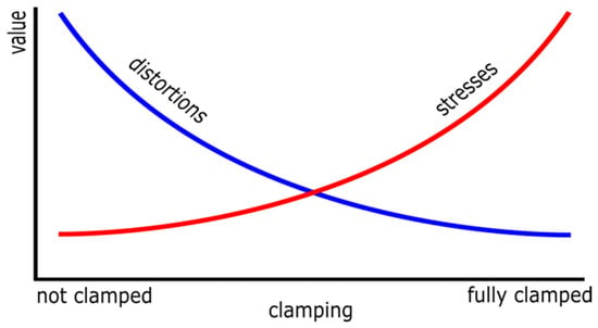
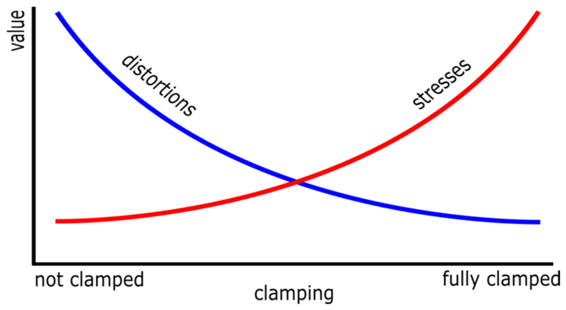
Residual stresses in welded joints are closely related to the formation of welding deformations. During cooling, the weld and the heat-affected zone contract, leading to changes in the geometry and dimensions of the structural components. The higher residual stresses level and the lower stiffness of the component result in bigger risk of welding deformation. In constructions with high weight and rigidity, deformations are negligible due to the dimensions of the structure, while the stresses are very high. On the other hand, in openwork and flexible welded structures, the deformations are very high, while the residual stresses are low, as shown in Figure 1. The task of the engineer is therefore to find this symmetry in the level of deformations and stresses that the welding process induces in the welded joint [6].
Figure 1.
Dependence of the deformations and stresses on the degree of clamping of welded elements [6].
All of them are formed because of uneven heating and cooling of the material during welding by travelling along the trajectory of the welding heat source. When components cannot change shape freely, e.g., due to the welded component clamping, internal stresses caused by thermal shrinkage occur instead of deformations. Additionally, tensile stresses are particularly dangerous because they can induce cracks initations. The values and distribution of stresses mainly depend on the type of material, joint geometry, welding technology, process parameters and the cooling conditions. To reduce stresses, appropriate technological methods are used, such as preheating, heat treatment after welding or the correct arrangement of welds and welding sequence [4,5,7].
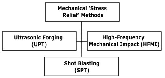
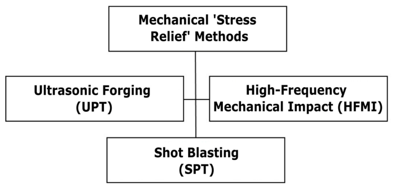
Therefore, in engineering practice, it is important to control both stresses and deformations simultaneously through appropriate welding technology, the sequence of welds and the use of clamping devices, as well as the post-weld treatment of welded joints. Methods of reducing welding stresses and deformations can be broadly divided into mechanical and thermal methods. In the case of mechanical methods, each method causes compressive stresses to be introduced in the material to be treated, or the yield strength is deliberately exceeded to reduce the tensile stresses values remaining in the material after the welding process. Figure 2 presents methods described in the literature, the use of which has been confirmed by research results [8,9,10].
Figure 2.
Classification of the most commonly used methods of stress relief of metal materials [10,11,12,13].
Mechanical stress relief is a popular method of stress reduction in welded joints and involves applying an external load to the welded joint to be machined, causing tensile stresses until the yield strength is exceeded. As a result of plastic deformation, the stress level decreases when the external strain load is removed [11,14,15].
Shot blasting, also known as a part of surface preparation technologies (SPTs), is often used in the processes of cleaning surfaces from rust and dirt. Proper execution of this process also allows for the introduction of compressive stresses into the material, and thus the reduction in the unused level of tensile stresses remains in the weld and HAZ after welding [13,16].
Ultrasonic impact machining (UIT) or ultrasonic mechanical forging (UMF) is also an effective tensile stress-reduction technology for welded joints. The use of high-frequency (20 kHz) and low-amplitude impacts causes strong plastic deformation of the surface, introducing compressive stresses into the material, which, on the superposition principle, reduce the unfavourable tensile residual stresses. This process allows you to reduce the stress level by up to 50% [12,17,18,19,20].
Classic peening is one of the most used in the welding industry. It consists of forging the structure after welding, mainly to clean it of slag formed because of thermo-chemical processes during welding. This method can be divided according to the equipment (it can be pneumatic or electric) and the method of use (manual or mechanised for repetitive operations). The tools used for drives usually resemble a chisel with a spherical tip made of hardened steel or carbide tip. The process has an elementary disadvantage in the form of a lack of precision and control over the process due to the recoil and impact energy of the tool [17,21,22].
Compared to conventional peening, the devices used in the High-Frequency Mechanical Impact (HFMI) process are more user-friendly due to the high frequency of operation during peening, which is in the range of 80–120 Hz. This device offers precise control of the process with significantly reduced impact on the operator performing the peening operation. Another advantage of the HFMI process is the machining results in a surface with an even mosaic, which is due to the small spacing between the impressions during impacts. The tools used in the process are very similar to those used in classic peening and are made of high-strength steel, and their geometry and shape depend on the goal to be achieved and access to the component. Tools can be radius-terminated, but it is also possible to use concave-shaped tools to remove sharp edges [10,23,24,25].
The primary application of this technology is to increase fatigue strength by peening the HAZ along with the fusion line. The mechanism that accompanies the reduction in stress concentration is the introduction of local compressive stresses in the machined area, in contrast to the commonly used technique of grinding or correcting the geometry of welds through local TIG remelting, which affects the visible surface and topography of the weld, but at the same time introduces an additional unfavourable stress distribution as a result of the local concentrated thermal cycle [24,26,27]. Due to the manual operation and very often work in forced positions, it may end in an adverse effect. The HFMI technique ensures that the geometry of the fusion line is changed and the residual stress is reduced [22]. Depending on the application, the device is equipped with different lengths and diameters of pins. In the case of high-precision machining, pins with a radius R = 1.5 mm are used, while for high-performance machining, pins with radius of R = 2.0–2.5 mm are most often used [28].
As a thermal method of reducing stresses and deformations, heat treatment is commonly used. It has a significant influence on the distribution of residual stresses and deformations that occur in welded joints. Heat treatment, especially stress-relieving annealing, allows for the partial or complete removal of these stresses by allowing the crystal structure to relax freely at elevated temperatures [13,29]. Annealing is a heat treatment operation consisting of heating the material to a certain temperature (depending on the production process of the base materials and their grade), subsequent annealing/holding at the constant temperature and cooling under specific conditions in terms of process dynamics. The purpose of this heat treatment is to obtain a structure similar to that before the welding process. In the case of stress-relieving annealing, the heating of steel consists of reaching a temperature lower than Ac1, annealing at this temperature and a slow cooling process. Characteristic for this heat treatment process is that it has almost no effect on the structure of the material. The ranges for temperature and process time are wide and basically it is the type of structural steel that determines these parameters. Typical range of stress-relieving annealing is a temperature between 530 °C and 650 °C [18]. Selected heat treatment parameters—temperature, times and cooling rate—determine the effectiveness of stress reduction and stabilisation of the weld joint geometry. Properly performed heat treatment improves both dimensional accuracy and service life of welded structures, which is crucial in applications that require high reliability, for example, energy, aerospace and machinery industry [18,30,31,32].
The aim of this article was to indicate the possibility of reducing the deformations and stresses of welded joints by using post-weld treatment. The deviations of flatness and straightness of welded joint plates measured with a laser tracker were compared for the following three cases: joints as welded, heat-treated joints and High-Frequency Mechanical Impact (HFMI)-processed joints for selected five grades of structural steels. In addition, numerical analyses were carried out to determine the impact of the post-weld processes on stress distributions. This knowledge is extremely important in typical engineering practice and allows for an easier decision for the engineer who is faced with the choice of how to process the joints after welding for both production and repair welding.
2. Materials and Methods
Five grades of structural steel—S235JR, S355J2+N, S460NL, S690QL and S960QL—were used in described research, as shown in Table 1. In addition, three types of filler materials were used for welding, depending on which base material was welded. For S235JR, S355J2+N and S460NL steels it was a 1.2 mm diameter welding wire with the trade name IMT-2 (EN ISO 14341-A—G3Si1) from Multimet Company (Przemków, Poland) [33]. For S690QL it was a 1.2 mm welding wire with the trade name IMT NiMoCr (EN ISO 16834-A—Mn3Ni1CrMo) from Multimet Company (Przemków, Poland) and for S960QL it was a 1.2 mm diameter wire with the trade name ED-FK 1000 (EN ISO 16834-A G 89 6 M21 Mn4Ni2CrMo) from Hermann Fliess & Co. GmbH (Duisburg, Germany) [34]. The chemical compositions of individual materials are presented in Table 2.
Table 1.
Chemical composition of welded plates based on Supplier’s Material Certificate.
Table 2.
Chemical composition of used filler materials based on Supplier’s Material Certificate.
2.1. Preparation of Welded Joints
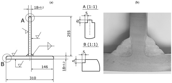
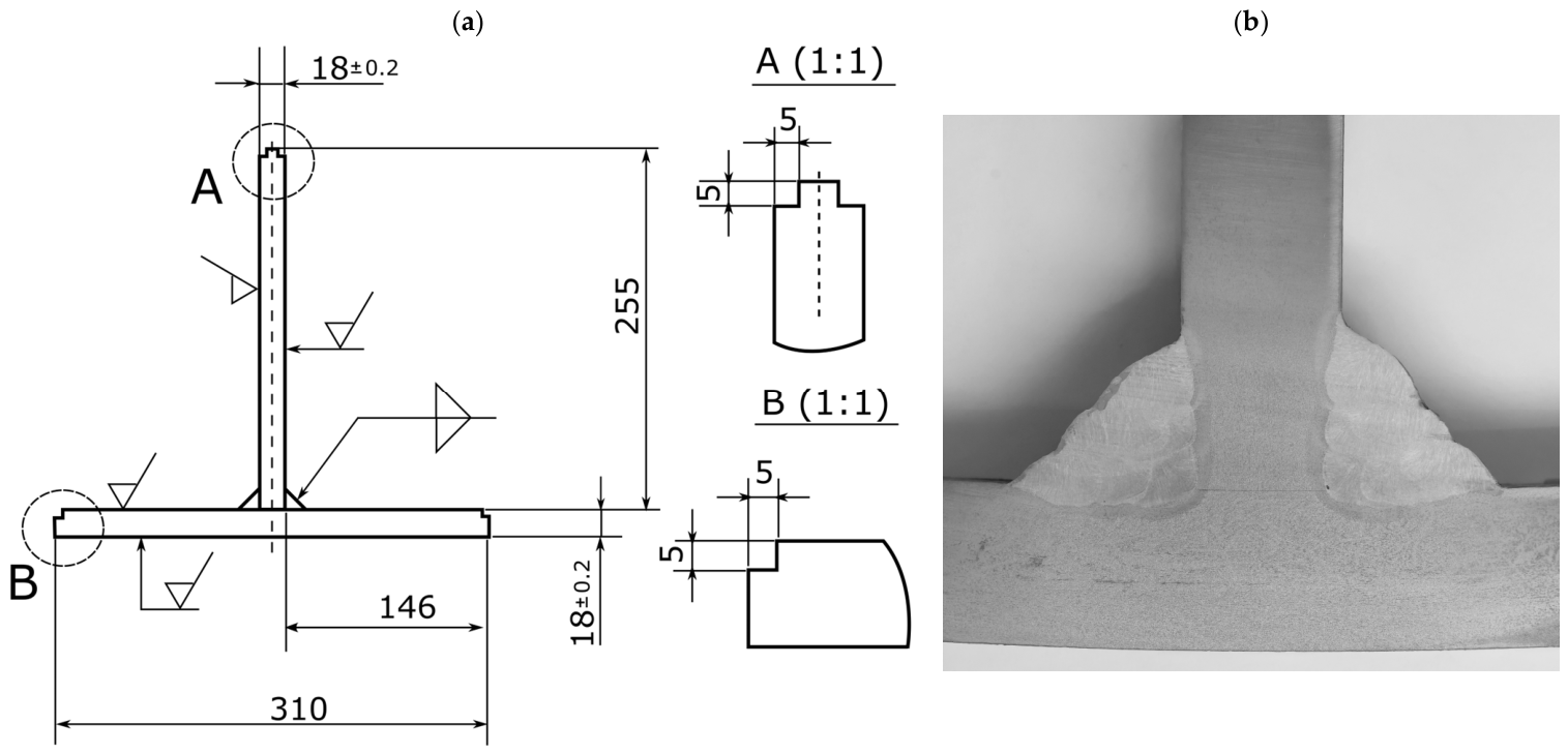
Tested T-joints were made from the plates with dimensions of 18 × 310 × 450 mm and 18 × 255 × 450 mm, which were prepared for welding. The initial thickness of the plates was 20 mm before alignment milling, which has been carried out to achieve the perfect flatness of the plates used in experiment, as shown in Figure 3.
Figure 3.
(a) Diagram of plate preparation for T-joint welding and (b) view of an example macrostructure of S355 steel welded joint.
The welding process was carried out manually using the MAG method (135). All welded joints were made by one welder in order to ensure comparable welding parameters for each of the test joints, such as: arc voltage, welding current, number of beads, welding speed or wire stick-out. The welding parameters were recorded by the welding data recorder (EWM Xnet 2.1 System) and each of the plates was welded to obtain a fillet weld with a minimum size of a12 on both sides. Shielding gas M20 (92% Ar + 8% CO2) was used for all tested materials. A summary of the welding parameters is presented in Table 3, Table 4, Table 5, Table 6 and Table 7 and in Figure 4, Figure 5, Figure 6, Figure 7 and Figure 8. Welding was performed simultaneously for all three plates of a given grade and therefore the interpass temperature did not exceed 40 °C when measured with a contact thermometer.
Table 3.
MAG welding parameters of T-joints of 18 mm thick S235JR steel plates for samples: as-welded, for heat treatment and interpass HFMI.
Table 4.
MAG welding parameters of T-joints of 18 mm thick S355J2+N steel plates for samples: as-welded, for heat treatment and interpass HFMI.
Table 5.
MAG welding parameters of T-joints of 18 mm thick S460NL steel plates for samples: as-welded, for heat treatment and interpass HFMI.
Table 6.
MAG welding parameters of T-joints of 18 mm thick S690QL steel plates for samples: as-welded, for heat treatment and interpass HFMI.
Table 7.
MAG welding parameters of T-joints of 18 mm thick S960QL steel plates for samples: as-welded, for heat treatment and interpass HFMI.
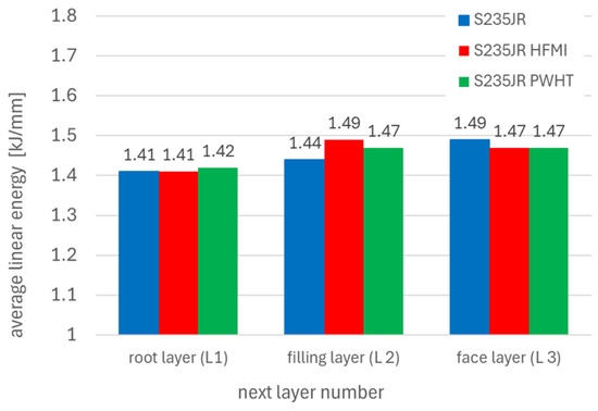
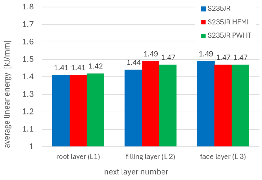
Figure 4.
Comparison of the average linear energy for individual layers in the welding process of S235JR steel T-joints.
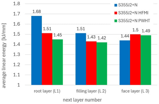
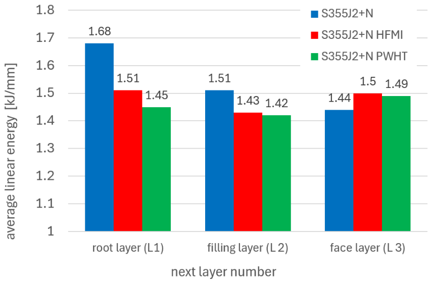
Figure 5.
Comparison of the average linear energy for individual layers in the welding process of S355J2+N steel T-joints.
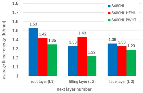
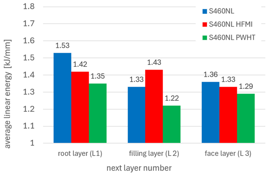
Figure 6.
Comparison of the average linear energy for individual layers in the welding process of S460NL steel T-joints.
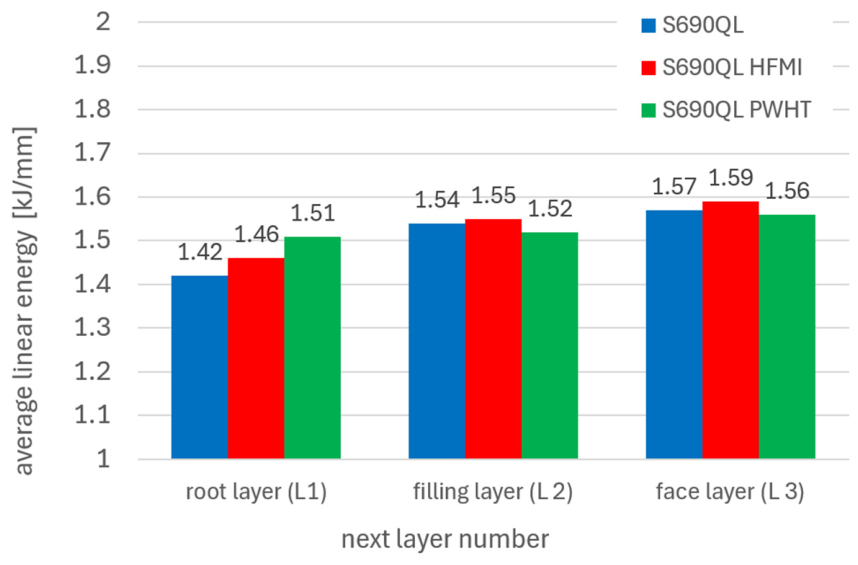
Figure 7.
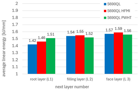
Comparison of the average linear energy for individual layers in the welding process of S690QL steel T-joints.
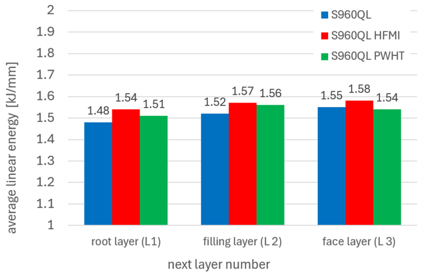
Figure 8.
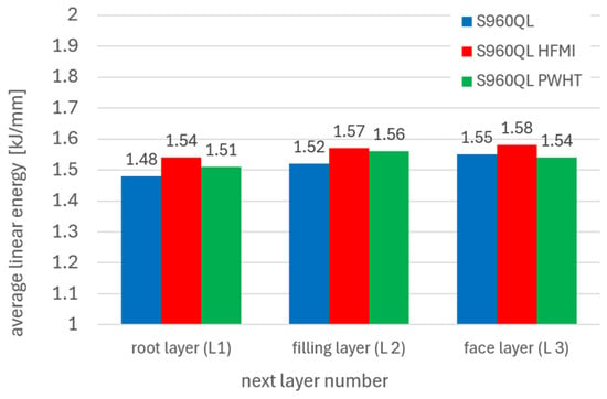
Comparison of the average linear energy for individual layers in the welding process of S960QL steel T-joints.
The obtained linear energy values for each of the individual beads indicate that welding in a partially mechanised mode by the same authorised welder allowed to obtain similar linear energy values. In a few cases, you can notice a difference in maximum about 15%; however, there is still a difference that was treated as acceptable in the context of human welding, as shown in Figure 4, Figure 5, Figure 6, Figure 7 and Figure 8.
All T-joints with double-sided fillet welds have been subjected to visual tests and weld size measurements. The comparison of weld sizes and quality level assessments in Table 8 testifies to the high repeatability of welding performed by the same authorised welder for all test joints.
Table 8.
Results of fillet weld size measurements in the middle of the joint length on both sides of the welds and quality evaluation according to ISO 5817-C [35].
2.2. Interpass High-Frequency Mechanical Impact Peening
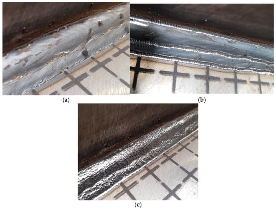
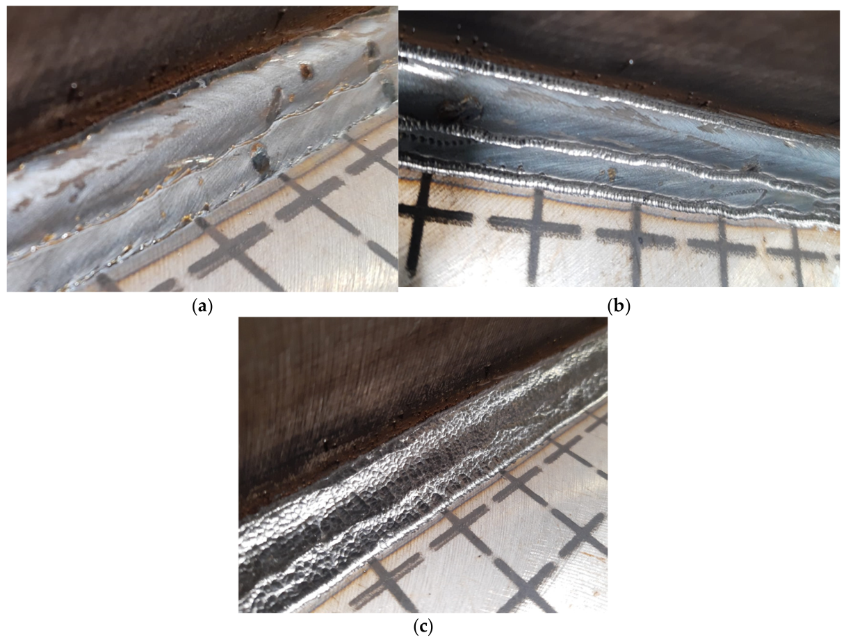
The high-frequency (90 Hz) peening of each bead performed was designed to reduce stress in the welded joint by introducing compressive stresses into it. A Weld Line 10 pneumatic hammer from PITEC GmbH (Kerpen, Germany) was used for this purpose. In order for the device to work effectively, it is necessary to ensure that the pressure in the compressed air system is between 4 and 7 bar. During the peening, the air pressure was about 6.0 bar. The correctness of HFMI was achieved when 100% of the surface of each bead including the face was processed, and the processing itself was carried out manually, as shown in Figure 9. The HFMI process was divided into two stages, the first of which was the re-forging in the area of the heat-affected zone (fillet weld embedding lines) with the use of a pin with a vertex radius of R = 1.5 mm, and then the re-forging of the remaining surface of the weld face with the replaced pin with a diameter of R = 2.0 mm. The peening speed was about 30 cm/min for the S235JR, S355J2+N and S460NL steel joints, and about 20 cm/min for the S690QL and S960QL steel joints, depending on the base and filler material.
Figure 9.
S355J2+N steel fillet weld face (a) after the second layer welding is completed, (b) the first HFMI step is done and (c) the second layer welding is completed after the HFMI process is completed.
2.3. Post-Weld Heat Treatment
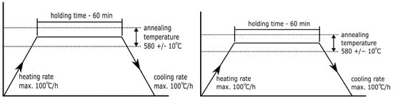
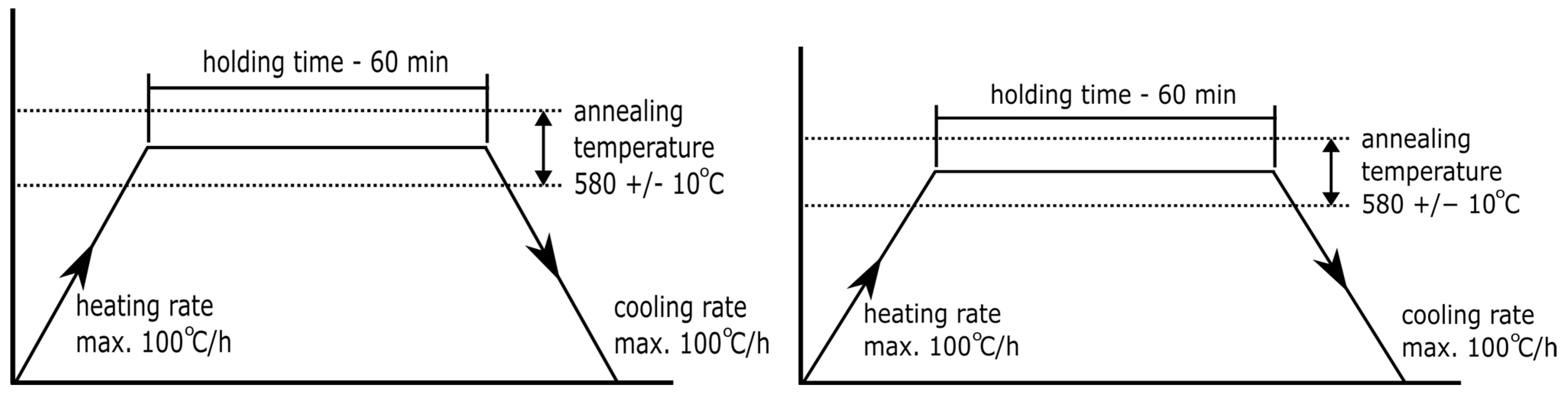
All PWHT samples after welding and non-destructive testing were heat-treated to reduce stress and deformation. The stress-relief annealing process was carried out with the use of resistance mats, which guaranteed very stable heat treatment conditions. The processing process was divided into the following three stages: controlled heating at 100 °C/h, sample annealing at 580 +/− 10 °C by 60 min and controlled cooling at 100 °C/h, as shown in Figure 10.
Figure 10.
Diagram of the PWHT of tested T-joints after welding.
2.4. Measurement of Deformations Using a Laser Tracker
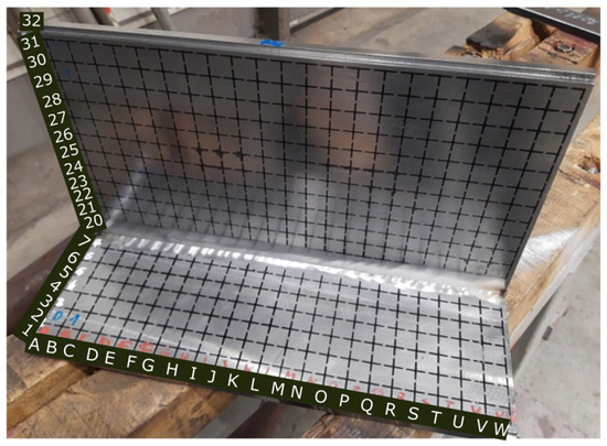
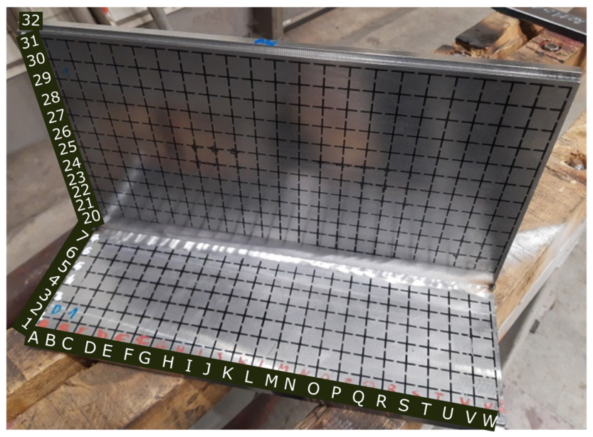
The API Radian PLUS R50 laser tracker (Automated Precision Inc. (API), Rockville, MD, USA) used for the measurements had a measurement accuracy of 0.7 μm/m. Before welding, it was necessary to take measurements using a laser tracker to measure the state of deformation after welding at the same measuring points. For this purpose, before welding each of the plates, a grid of evenly distributed measuring points was applied to their surface. The mesh of the measuring points was then applied to the plates prepared for welding, as shown in Figure 11.
Figure 11.
Welded T-joint prepared for measurements with a routed grid of points.
Before and after the completion of welding and post-weld treatment processes (HFMI or PWHT), the deformation was measured by determining the differences in the flatness of the plates before and after welding, and as a second parameter, the differences in the straightness of each plate were determined by comparing the points A0-W0, A15-W15, A32-W32 and A33-W33 for each of the plates before and after welding. These points were located in milled grooves on the outer edges of the welded plates, as shown in Figure 3a and Figure 11. In total, there were 345 measuring points on each horizontal plate, 276 on the vertical plate and 23 measuring points on each of the 4 milling lines at the ends of the plates. The precision of the measurements can be evidenced by the total sum of 713 measurements for each tested specimen.
3. Results
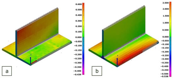
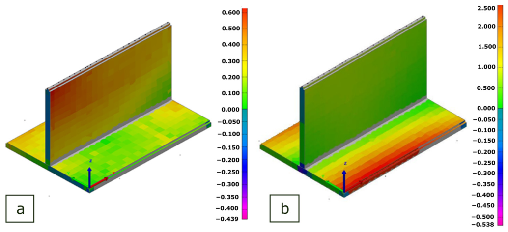
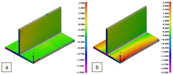
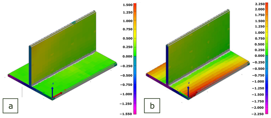
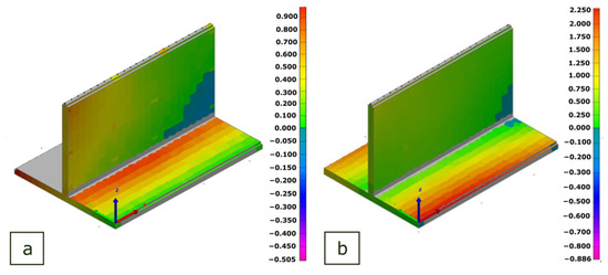
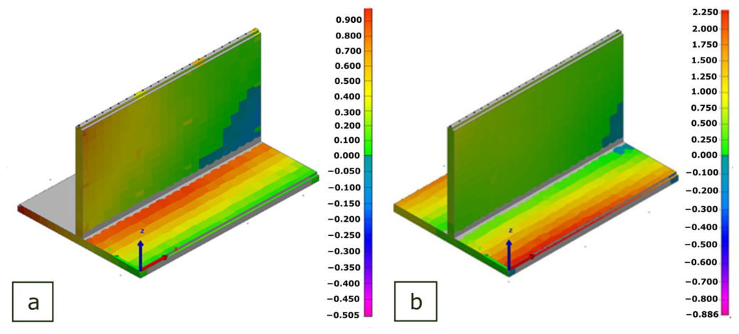
This analysis was based on a comparison of three T-joints welded on both sides with fillet welds, made of plates in five grades of structural steels, as shown in Table 1. Flatness and straightness deviation measurements were performed for samples in the following condition: after welding, after heat treatment and interpass HFMI. All test joints were measured before, after welding and after the implementation of post-weld treatment processes (PWHT or HFMI). Thanks to the use of modern software for the analysis of measurements carried out with the use of a laser tracker, it was possible to create a three-dimensional model of welded joints, which allows for easier analysis of the results. Examples of such models for S690QL T-joints are shown in Figure 12, Figure 13 and Figure 14.
Figure 12.
S690QL test joint (a) before welding and (b) after welding—analysis performed in API Metrology Software—MeasurePro 2026-R2.
Figure 13.
S690QL test joint (a) before welding and (b) after welding and HFMI—analysis performed in API Metrology Software—MeasurePro 2026-R2.
Figure 14.
S690QL test joint (a) before welding and (b) after welding and PWHT—analysis performed in API Metrology Software—MeasurePro 2026-R2.
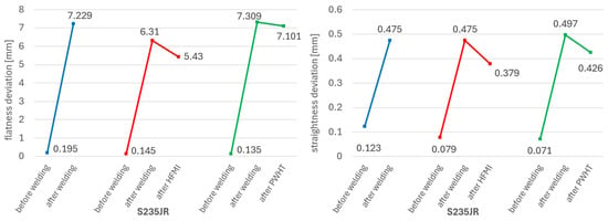
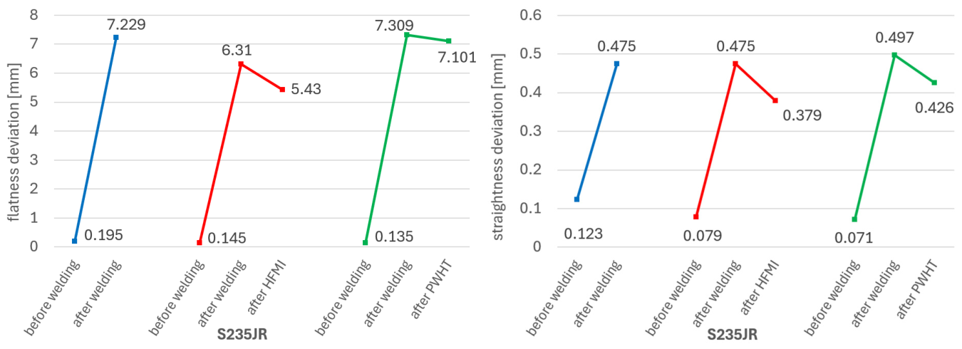
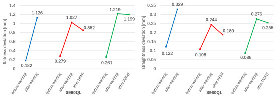
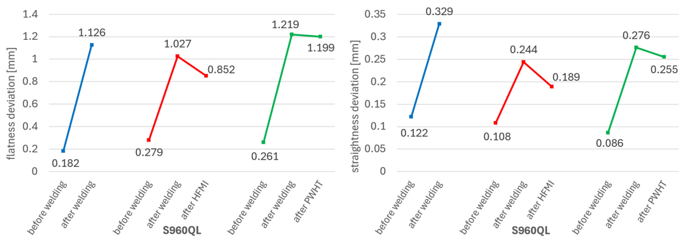
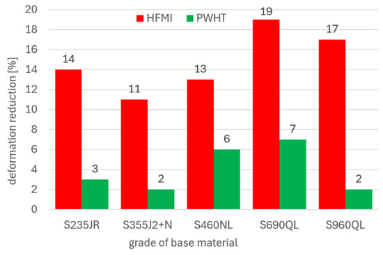
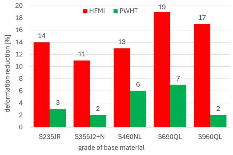
A comparison of the measurement results is presented in Figure 15, Figure 16, Figure 17, Figure 18 and Figure 19. A list of differences in the scope of deformation reduction is presented in Figure 20.
Figure 15.
Comparison of the measurement results of flatness deviation of the panel plate and straightness deviation of the web plate in S235JR steel T-joint for different types of joint processing after welding.
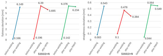
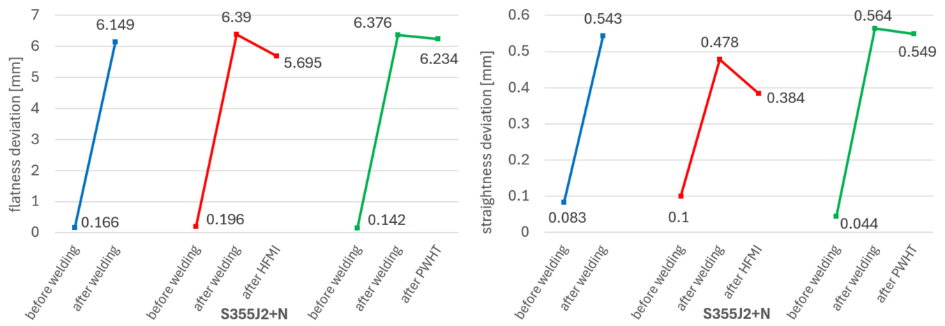
Figure 16.
Comparison of the measurement results of flatness deviation of the panel plate and straightness deviation of the web plate in S355J2+N steel T-joint for different types of joint processing after welding.
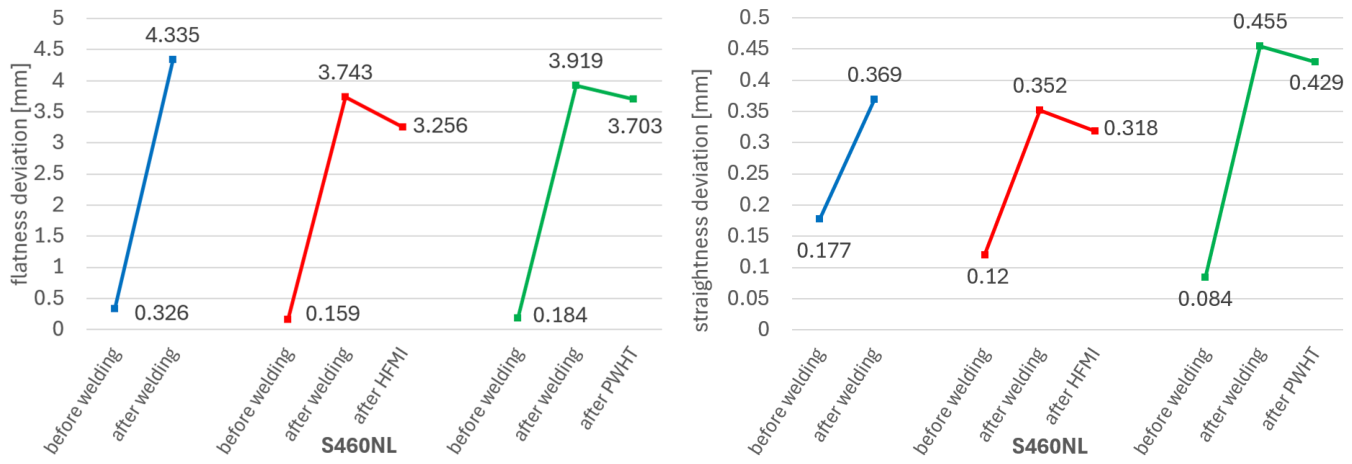
Figure 17.
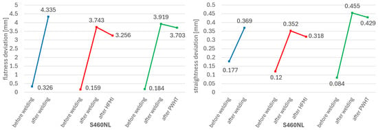
Comparison of the measurement results of flatness deviation of the panel plate and straightness deviation of the web plate in S460NL steel T-joint for different types of joint processing after welding.
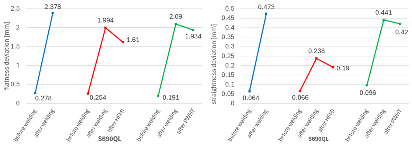
Figure 18.
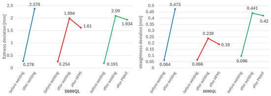
Comparison of the measurement results of flatness deviation of the panel plate and straightness deviation of the web plate in S690QL steel T-joint for different types of joint processing after welding.
Figure 19.
Comparison of the measurement results of flatness deviation of the panel plate and straightness deviation of the web plate in S960QL steel T-joint for different types of joint processing after welding.
Figure 20.
Comparison of deformation reduction as a function of base material grade and post-weld treatment process used.
An Attempt to Model Welding and Post-Weld Processing Using FEM
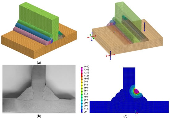
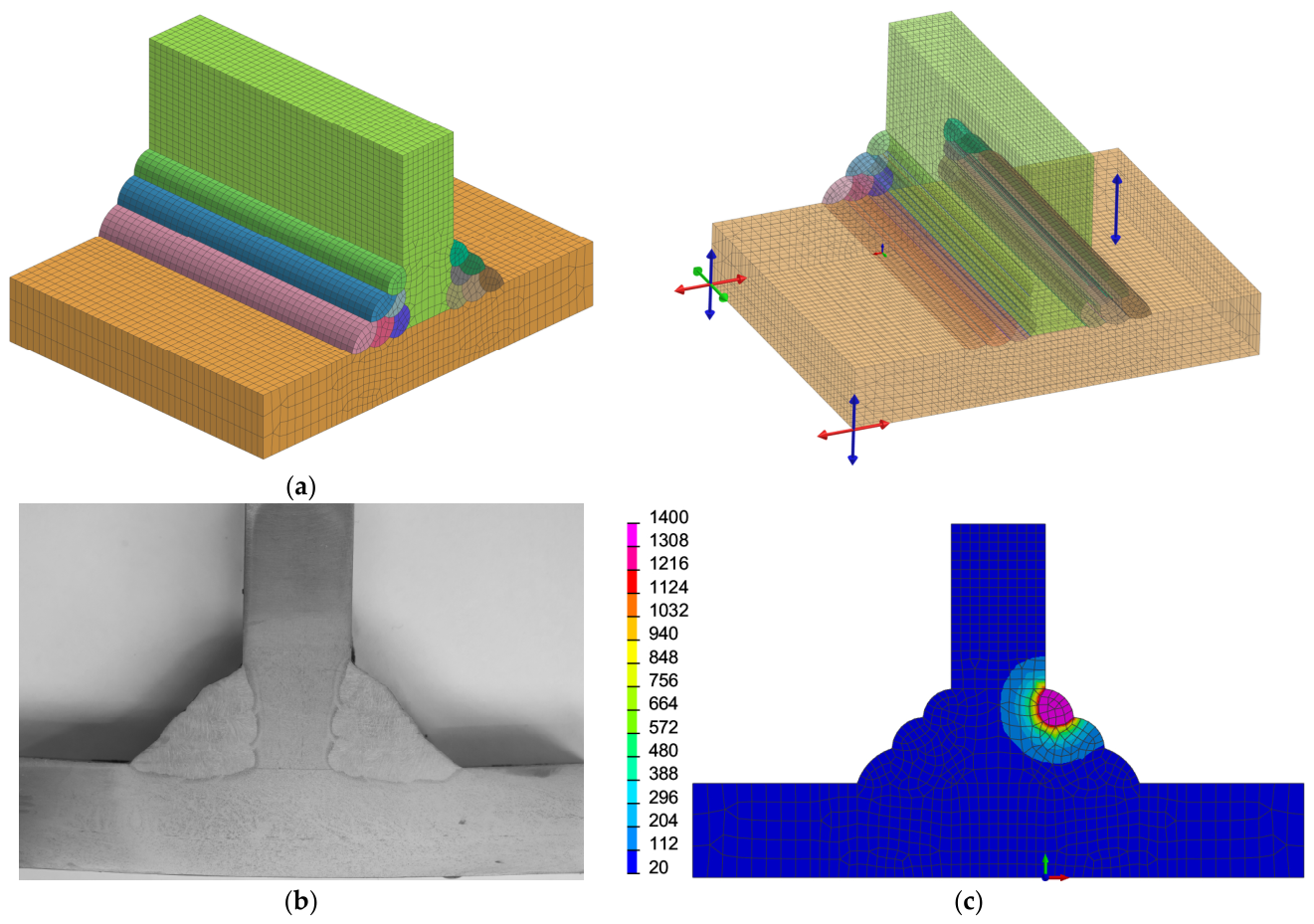
Observing the changes in flatness and straightness of the samples in the results of the tests, an attempt was also made to determine the influence of post-weld treatment on the stress distribution in the analysed samples. The calculation method was chosen because it is very difficult, even impossible, to experimentally determine the stress distribution in welded joints, especially on the cross-section (inside the weld). Analyses were performed in SYSWELD 2026.0 (Keysight Technologies, Santa Rosa, CA, USA). For this purpose, a three-dimensional discrete model was built, which consisted of 37,576 nodes and 44,432 elements, as shown in Figure 21a. The conditions for the welding element clamping have been selected to reflect the actual fixing conditions of the samples, as shown in Figure 21b. The boundary condition describing the heat dissipation to the environment was defined by radiation and convection heat dissipation to an ambient temperature of 20 °C on all the external surfaces of the model. For these surfaces, the temperature-independent coefficient of convective heat transfer α = 25 W/m2K and surface emissivity of ε = 0.8 were assumed. Based on macrostructure images, a model of the heat source for each of the welded beads was calibrated. The heat source model used in these analyses was a moving double ellipsoidal model (Goldak model) modified with the ability to select the mesh elements loaded with the heat source model [6,36]. Such consideration allows for a much more accurate reproduction of the shape of the molten metal pool [6,36]. The welding sequence with the parameters was a representation of the actual welding sequence of the recorded welding parameters during the welding work, which allowed for the calibration of the heat source model and obtaining simulation conditions corresponding to the real welding process, as shown in Figure 21c.
Figure 21.
View of (a) the 3D numerical model with the clamping conditions, (b) the macrostructure of the S355 steel T-joint and (c) the temperature distribution during welding calculated during the calibration of the heat source model of one of the beads of the third layer.
The HFMI processing was modelled as a surface deformation corresponding to the actual one measured in experimental studies. In the literature, there is a similar approach to modelling [36,37,38,39] of this process, while more often there is an approach where the welding process itself is modelled in Sysweld software [30], while the obtained model with a specific state of stresses and deformation is further analysed in terms of peening, or rather plastic deformation in Abaqus software [25,40,41,42,43].
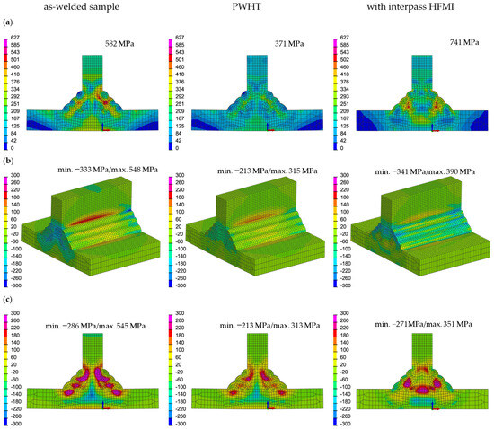
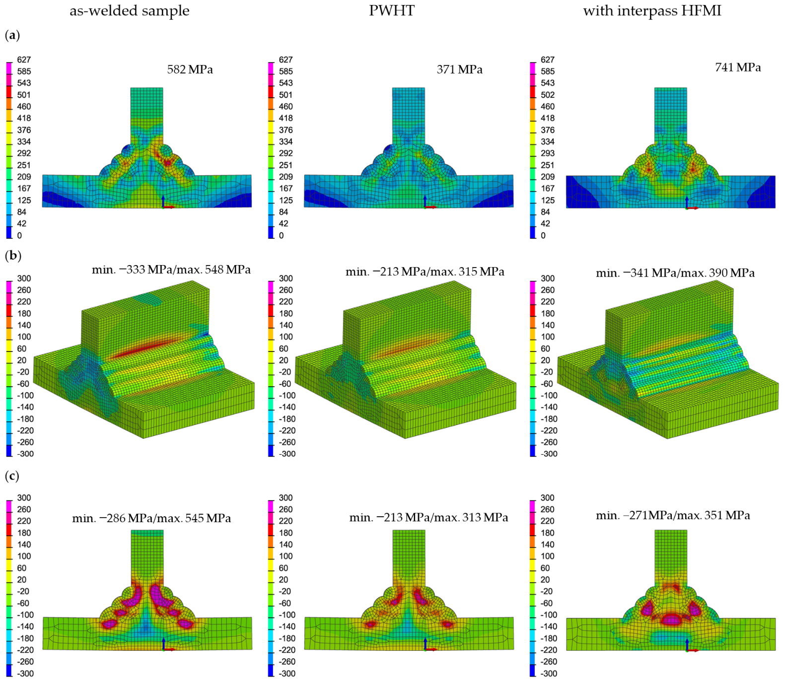
Figure 22 shows residual stresses (von Mises) and mean stress distributions for the three analysed variants of the S355 steel welded T-joint.
Figure 22.
Stress distribution: (a) von Mises, (b) mean and (c) mean stress on the cross-section of the joint (mid-length) for the S355 T-joint.
4. Discussion
The aim of the work was to demonstrate that it is possible to control stresses and deformations in welded joints by applying additional processing of the joints after welding. This is extremely important in the case of repairs on already very precisely machined structures, where classic heat treatment is usually not possible. The analysis of the measured deformations, depending on the processing after welding, shows the advantage of using HFMI technology over PWHT in the context of reducing deformation during and after welding for each of the analysed base material variants. This difference is quite large and ranges from 7 to 19% depending on the material grade to be welded, as shown in Figure 20. In the case of PWHT, the values by which the deviations of flatness and straightness decreased were in the range of 2 to 7%. It should also be noted that the values of deviations, both flatness and straightness, decrease depending on the welded material, and the nature of their occurrence, despite manual welding and HFMI processing, was similar. The highest deviation values were obtained for S235JR steel (on average about 6.3 to 7.3 mm after welding and 5.4–7.1 mm after PWHT), and as the yield strength value increased, it reached the lowest values for the S960QL steel joint (on average about 1.0 to 1.2 mm after welding and 0.85–1.2 mm after heat treatment), as shown in Figure 15, Figure 16, Figure 17, Figure 18 and Figure 19. It is also worth noting that in the case of heat-treated steel, the use of PWHT is associated with limitations due to the high tempering temperature. With these materials, this is not limited to HFMI processing, which is another advantage of this technique.
In the stress distribution analysis, the situation is different. Here, heat treatment significantly reduces the residual stress values in the analysed T-joint compared to the HFMI application variant. During PWHT, the reduced stresses (von Mises) are reduced from about 582 MPa to 371 MPa, i.e., by about 37%. In the case of HFMI, on the other hand, these values even increase locally by about 27%, which is probably caused by a local change in the character and stress values in individual areas of the welded joint. Such a relationship is fully justified and is caused by the fact that the larger deformations obtained in the case of PWHT allow for the relaxation of residual stresses. HFMI, on the other hand, acts more on the bead surface, which is visible in the results of numerical analyses (Figure 22) and with lower deformation values, but a certain level of residual stresses is maintained. In addition, in the case of the sample after PWHT, a decrease in the stress levels is visible in the entire joint volume. In the case of HFMI, on the other hand, compressive stress areas are created at the points adjacent to the peening areas, at the same time as the tensile stress area is shifted to the centre of the welded joint. What should also be noted, in the case of PWHT, the values of average stresses are reduced by about 35–40% compared to the sample without post-welding processing. In the case of HFMI, this relationship does not occur, and the values are similar in terms of compressive stresses, while tensile stresses are reduced by about 30–35%, as shown in Figure 22.
To sum up, it should be stated that the HFMI affects the state of welding deformation in T-welded joints, resulting in a reduction in deformation. As demonstrated in deformation reduction, HFMI technology is much more effective than stress-relief annealing. Analysing the results of the numerical calculations, it should be stated that the HFMI peening technology used reduces the stress state of welded joints compared to joints without additional processing. However, it is not as effective as stress-relieving annealing in terms of reducing residual stresses.
The next step considered by the authors is a detailed analysis of the displacement distributions and interdependencies of induced stresses in the numerical model and the creation of complete information supported by the results of numerical analyses and deformation measurements.
5. Conclusions
Based on the presented research and analyses of the post-weld treatment process influence on deformations and stress distributions in welded T-joints, it was found that:
- -
- The use of additional treatment of joints after welding reduces the level of deformation of welded elements both in the case of PWHT in the range of 11 to 19%, and in the case of HFMI in a smaller range from 2 to 7%;
- -
- With the increase in the strength properties of the welded material (the use of a higher grade of steel, i.e., an increase in the stock of elastic deformation of the material), the size of the measured values of flatness and straightness deviation decreases in all analysed cases;
- -
- The use of PWHT significantly reduces the overall level of reduced stresses (von Mises) in the analysed joint from a maximum of 582 MPa to 371 MPa. In the case of HFMI, these values are even higher in certain areas (max. 741 MPa), which results from the local forging of individual layers;
- -
- In cases with additional processing of joints after welding, the distribution of mean stresses for the analysed case of S355 steel T-joints welding is more uniform in the case of PWHT use;
- -
- The average stress values are reduced in terms of reducing the level of compressive and tensile stresses after the PWHT by about 30–40%, but in the case of HFMI, only the levels of tensile stress values are reduced.
Author Contributions
Conceptualization, J.G., T.K. and M.P.; methodology, M.P.; software, T.K.; validation, J.G., T.K. and M.P.; formal analysis, J.G. and M.P.; investigation, J.G., T.K. and M.P.; resources, M.P.; data curation, M.P. and J.G.; writing—original draft preparation, T.K.; writing—review and editing, T.K.; visualisation, T.K. and M.P.; supervision, J.G.; project administration, J.G. All authors have read and agreed to the published version of the manuscript.
Funding
This research received no external funding.
Data Availability Statement
The original contributions presented in this study are included in the article. Further inquiries can be directed to the corresponding author.
Conflicts of Interest
Author Mateusz Przybyła was employed by the company FAMET S.A. The remaining authors declare that the research was conducted in the absence of any commercial or financial relationships that could be construed as a potential conflict of interest.
References
- Björk, T.; Ahola, A.; Tuominen, N. On the Design of Fillet Welds Made of Ultra-High-Strength Steel. Weld. World 2018, 62, 985–995. [Google Scholar] [CrossRef] [Scilit]
- Outinen, J.; Mäkeläinen, P. Mechanical Properties of Structural Steel at Elevated Temperatures and after Cooling Down. Fire Mater. 2004, 28, 237–251. [Google Scholar] [CrossRef] [Scilit]
- Güney, B. Microstructure analysis of welding fume of low and medium carbon steels. Rev. Metal. 2021, 57, e187. [Google Scholar] [CrossRef] [Scilit]
- Ghafouri, M.; Ahola, A.; Ahn, J.; Björk, T. Welding-Induced Stresses and Distortion in High-Strength Steel T-Joints: Numerical and Experimental Study. J. Constr. Steel Res. 2022, 189, 107088. [Google Scholar] [CrossRef] [Scilit]
- Michaleris, P. Introduction to Welding Residual Stress and Distortion. In Minimization of Welding Distortion and Buckling: Modelling and Implementation; Woodhead Publishing: Sawston, UK, 2011; pp. 3–22. [Google Scholar]
- Kik, T. Predykcja Własności Złączy Spawanych z Wykorzystaniem Zaawansowanych Modeli Źródeł Ciepła; Wydawnictwo Politechniki Śląskiej: Gliwice, Poland, 2022; Volume 931, p. 200. (In Polish) [Google Scholar]
- Colegrove, P.; Ikeagu, C.; Thistlethwaite, A.; Williams, S.; Nagy, T.; Suder, W.; Steuwer, A.; Pirling, T. Welding Process Impact on Residual Stress and Distortion. Sci. Technol. Weld. Join. 2009, 14, 717–725. [Google Scholar] [CrossRef] [Scilit]
- Haagensen, P.J. Fatigue Strength Improvement Methods. In Fracture and Fatigue of Welded Joints and Structures; Woodhead Publishing: Sawston, UK, 2011; pp. 297–329. [Google Scholar] [CrossRef] [Scilit]
- Agerskov, H.; Hansen, A.; Bjørnbak-Hansen, J.; Olesen, J. Improvement of Fatigue Life of Welded Structural Components of a Large Two-Stroke Diesel Engine by Grinding. Weld. World 2004, 48, 56–60. [Google Scholar] [CrossRef] [Scilit]
- Berg, J.; Stranghoener, N. Fatigue Strength of Welded Ultra High Strength Steels Improved by High Frequency Hammer Peening. Procedia Mater. Sci. 2014, 3, 71–76. [Google Scholar] [CrossRef] [Scilit]
- Chuvas, T.C.; Castello, D.A.; Cindra Fonseca, M.P. Residual Stress Relief of Welded Joints by Mechanical Vibrations. J. Braz. Soc. Mech. Sci. Eng. 2016, 38, 2449–2457. [Google Scholar] [CrossRef] [Scilit]
- Liu, C.; Yan, Y.; Cheng, X.; Wang, C.; Zhao, Y. Residual Stress in a Restrained Specimen Processed by Post-Weld Ultrasonic Impact Treatment. Sci. Technol. Weld. Join. 2019, 24, 193–199. [Google Scholar] [CrossRef] [Scilit]
- Malekahmadi, A.; Honarpisheh, M. Investigation of Shot Blasting and Thermal Stress Relieving Processes on Residual Stresses and Corrosion Behavior of X60 Steel Gas Pipelines. SN Appl. Sci. 2020, 2, 1593. [Google Scholar] [CrossRef] [Scilit]
- Yang, Y.P. Understanding of Vibration Stress Relief with Computation Modeling. J. Mater. Eng. Perform. 2009, 18, 856–862. [Google Scholar] [CrossRef] [Scilit]
- Zha, F.-C.; Wang, Y.-Q.; Liu, Z.-H.; Wang, R.; Ji, H.-B.; Zhong, Y.-Q.; Chen, C.-Q. Experimental and Numerical Study on Residual Stresses Relief in 316 L Austenitic Stainless Steel Welded Joints Using Layer-by-Layer Ultrasonic Impact Treatment. J. Constr. Steel Res. 2025, 233, 109666. [Google Scholar] [CrossRef] [Scilit]
- Kanchidurai, S.; A Krishanan, P.; Baskar, K.; Mohan, K.S.R. A Review of Inducing Compressive Residual Stress—Shot Peening; on Structural Metal and Welded Connection. In IOP Conference Series Earth and Environmental Science; IOP Publishing: Bristol, UK, 2017; Volume 80, p. 012033. [Google Scholar] [CrossRef] [Scilit]
- Kudryavtsev, Y. Fatigue Improvement of Welded Elements by Ultrasonic Impact Treatment. In Proceedings of the Experimental and Applied Mechanics, Volume 6; Proulx, T., Ed.; Springer: New York, NY, USA, 2011; pp. 75–87. [Google Scholar]
- Liu, C.; Shen, J.; Yan, J.; Chu, Q.; Wang, J.; Zhao, Y. Experimental Investigations on Welding Stress Distribution in Thick Specimens After Postweld Heat Treatment and Ultrasonic Impact Treatment. J. Mater. Eng. Perform. 2020, 29, 1820–1829. [Google Scholar] [CrossRef] [Scilit]
- Hu, X.; Ma, C.; Yang, Y.; Zeng, Q. Study on Residual Stress Releasing of 316L Stainless Steel Welded Joints by Ultrasonic Impact Treatment. Int. J. Steel Struct. 2020, 20, 1014–1025. [Google Scholar] [CrossRef] [Scilit]
- Zhang, Q.; Yu, L.; Shang, X.; Zhao, S. Residual Stress Relief of Welded Aluminum Alloy Plate Using Ultrasonic Vibration. Ultrasonics 2020, 107, 106164. [Google Scholar] [CrossRef] [Scilit] [PubMed]
- Bleicher, F.; Lechner, C.; Habersohn, C.; Obermair, M.; Heindl, F.; Rodriguez Ripoll, M. Improving the Tribological Characteristics of Tool and Mould Surfaces by Machine Hammer Peening. CIRP Ann.—Manuf. Technol. 2013, 62, 239–242. [Google Scholar] [CrossRef] [Scilit]
- Bleicher, F.; Lechner, C.; Habersohn, C.; Kozeschnik, E.; Adjassoho, B.; Kaminski, H. Mechanism of Surface Modification Using Machine Hammer Peening Technology. CIRP Ann. 2012, 61, 375–378. [Google Scholar] [CrossRef] [Scilit]
- Ghahremani, K.; Ranjan, R.; Walbridge, S.; Ince, A. Fatigue Strength Improvement of Aluminum and High Strength Steel Welded Structures Using High Frequency Mechanical Impact Treatment. Procedia Eng. 2015, 133, 465–476. [Google Scholar] [CrossRef] [Scilit]
- Weinert, J.; Gkatzogiannis, S.; Engelhardt, I.; Knoedel, P.; Ummenhofer, T. Application of high frequency mechanical impact treatment to improve the fatigue strength of corroding welded joints. Weld. World 2021, 65, 2157. [Google Scholar] [CrossRef] [Scilit]
- Deng, C.; Liu, Y.; Gong, B.; Wang, D. Numerical Implementation for Fatigue Assessment of Butt Joint Improved by High Frequency Mechanical Impact Treatment: A Structural Hot Spot Stress Approach. Int. J. Fatigue 2016, 92, 211–219. [Google Scholar] [CrossRef] [Scilit]
- Lieurade, H.-P.; Huther, I.; Lefebvre, F. Effect of Weld Quality and Postweld Improvement Techniques on the Fatigue Resistance of Extra High Strength Steels. Weld. World 2008, 52, 106–115. [Google Scholar] [CrossRef] [Scilit]
- Pedersen, M.M.; Mouritsen, O.Ø.; Hansen, M.R.; Andersen, J.G.; Wenderby, J. Comparison of Post-Weld Treatment of High-Strength Steel Welded Joints in Medium Cycle Fatigue. Weld. World 2010, 54, R208–R217. [Google Scholar] [CrossRef] [Scilit]
- Le Quilliec, G. Application Du Martelage à Haute Fréquence à l’optimisation de La Maintenance Des Ouvrages et Des Structures Soudées. Ph.D. Thesis, University of Tours, Tours, France, 2011. [Google Scholar]
- Song, H.; Gao, H.; Wu, Q.; Zhang, Y. Residual Stress Relief Mechanisms of 2219 Al–Cu Alloy by Thermal Stress Relief Method. Rev. Adv. Mater. Sci. 2022, 61, 102–116. [Google Scholar] [CrossRef] [Scilit]
- Kik, T.; Moravec, J.; Švec, M. Experiments and Numerical Simulations of the Annealing Temperature Influence on the Residual Stresses Level in S700MC Steel Welded Elements. Materials 2020, 13, 5289. [Google Scholar] [CrossRef] [Scilit] [PubMed]
- Jiang, W.; Luo, Y.; Zeng, Q.; Wang, J.; Tu, S.-T. Residual Stresses Evolution during Strip Clad Welding, Post Welding Heat Treatment and Repair Welding for a Large Pressure Vessel. Int. J. Press. Vessel. Pip. 2021, 189, 104259. [Google Scholar] [CrossRef] [Scilit]
- Zhao, M.S.; Chiew, S.; Lee, C.K. Post Weld Heat Treatment for High Strength Steel Welded Connections. J. Constr. Steel Res. 2016, 122, 167–177. [Google Scholar] [CrossRef] [Scilit]
- ISO 14341-A:2020; Welding Consumables—Wire Electrodes and Weld Deposits for Gas Shielded Metal arc Welding of Non Alloy and Fine Grain Steels—Classification. ISO: Geneva, Switzerland, 2020.
- ISO 16834-A:2012; Welding Consumables—Wire Electrodes, Wires, Rods and Deposits for Gas Shielded arc Welding of High strength steels—Classification. ISO: Geneva, Switzerland, 2012.
- ISO 5817-C:2014; Welding—Fusion-Welded Joints in Steel, Nickel, Titanium and Their Alloys (Beam Welding Excluded)—Quality Levels for Imperfections. ISO: Geneva, Switzerland, 2014.
- Kik, T.; Garašić, I.; Perić, M.; Landek, D.; Jurica, M.; Tonković, Z. Modifications of the Heat Source Model in Numerical Analyses of the Metal-Cored Arc Welding Process. Energy 2024, 302, 131811. [Google Scholar] [CrossRef] [Scilit]
- Tho, K.K.; Swaddiwudhipong, S.; Liu, Z.S.; Zeng, K. Simulation of Instrumented Indentation and Material Characterization. Mater. Sci. Eng. A 2005, 390, 202–209. [Google Scholar] [CrossRef] [Scilit]
- Lee, H.; Lee, J.H.; Pharr, G. A Numerical Approach to Spherical Indentation Techniques for Material Property Evaluation. J. Mech. Phys. Solids 2005, 53, 2037–2069. [Google Scholar] [CrossRef] [Scilit]
- Perić, M.; Garašić, I.; Gubeljak, N.; Tonković, Z.; Nižetić, S.; Osman, K. Numerical Simulation and Experimental Measurement of Residual Stresses in a Thick-Walled Buried-Arc Welded Pipe Structure. Metals 2022, 12, 1102. [Google Scholar] [CrossRef] [Scilit]
- Perić, M.; Garašić, I.; Nižetić, S.; Dedić-Jandrek, H. Numerical Analysis of Longitudinal Residual Stresses and Deflections in a T-Joint Welded Structure Using a Local Preheating Technique. Energies 2018, 11, 3487. [Google Scholar] [CrossRef] [Scilit]
- Hardenacke, V.; Farjian, M.; Siegele, D. Modelling and Simulation of the High Frequency Mechanical Impact (HFMI) Treatment of Welded Joints. Available online: https://publica.fraunhofer.de/handle/publica/400515 (accessed on 23 June 2026).
- Rahman, M.M.; Enzinger, N.; Sommitsch, C. Deformation and Distortion Induced by Pneumatic Impact Treatment (PIT) in a Welded Joint for HS Steel. In Proceedings of Teh IWOTE′11: International Workshop on Thermal Forming and Welding Distortion; BIAS Verlag: Bremen, Germany, 2011; Volume 41, pp. 203–214. [Google Scholar]
- Yıldırım, H.; Marquis, G.; Barsoum, Z. Fatigue Assessment of High Frequency Mechanical Impact (HFMI)-Improved Fillet Welds by Local Approaches. Int. J. Fatigue 2013, 52, 57–67. [Google Scholar] [CrossRef] [Scilit]

Disclaimer/Publisher’s Note: The statements, opinions and data contained in all publications are solely those of the individual author(s) and contributor(s) and not of MDPI and/or the editor(s). MDPI and/or the editor(s) disclaim responsibility for any injury to people or property resulting from any ideas, methods, instructions or products referred to in the content. |
© 2026 by the authors. Licensee MDPI, Basel, Switzerland. This article is an open access article distributed under the terms and conditions of the Creative Commons Attribution (CC BY) license.